EP4002969A1 - Universal equipment rack for telecommunications cabinets - Google Patents
Universal equipment rack for telecommunications cabinets Download PDFInfo
- Publication number
- EP4002969A1 EP4002969A1 EP21208444.6A EP21208444A EP4002969A1 EP 4002969 A1 EP4002969 A1 EP 4002969A1 EP 21208444 A EP21208444 A EP 21208444A EP 4002969 A1 EP4002969 A1 EP 4002969A1
- Authority
- EP
- European Patent Office
- Prior art keywords
- bracket
- structural rail
- mounting holes
- equipment rack
- insert plate
- Prior art date
- Legal status (The legal status is an assumption and is not a legal conclusion. Google has not performed a legal analysis and makes no representation as to the accuracy of the status listed.)
- Granted
Links
Images


Classifications
-
- H—ELECTRICITY
- H05—ELECTRIC TECHNIQUES NOT OTHERWISE PROVIDED FOR
- H05K—PRINTED CIRCUITS; CASINGS OR CONSTRUCTIONAL DETAILS OF ELECTRIC APPARATUS; MANUFACTURE OF ASSEMBLAGES OF ELECTRICAL COMPONENTS
- H05K7/00—Constructional details common to different types of electric apparatus
- H05K7/18—Construction of rack or frame
- H05K7/183—Construction of rack or frame support rails therefor
-
- H—ELECTRICITY
- H04—ELECTRIC COMMUNICATION TECHNIQUE
- H04Q—SELECTING
- H04Q1/00—Details of selecting apparatus or arrangements
- H04Q1/02—Constructional details
- H04Q1/025—Cabinets
-
- H—ELECTRICITY
- H04—ELECTRIC COMMUNICATION TECHNIQUE
- H04Q—SELECTING
- H04Q1/00—Details of selecting apparatus or arrangements
- H04Q1/02—Constructional details
- H04Q1/09—Frames or mounting racks not otherwise provided for
-
- H—ELECTRICITY
- H05—ELECTRIC TECHNIQUES NOT OTHERWISE PROVIDED FOR
- H05K—PRINTED CIRCUITS; CASINGS OR CONSTRUCTIONAL DETAILS OF ELECTRIC APPARATUS; MANUFACTURE OF ASSEMBLAGES OF ELECTRICAL COMPONENTS
- H05K7/00—Constructional details common to different types of electric apparatus
- H05K7/18—Construction of rack or frame
- H05K7/186—Construction of rack or frame for supporting telecommunication equipment
Definitions
- the present invention relates generally to telecommunications cabinets, and more specifically to a universal equipment rack for telecommunications cabinets.
- Outdoor telecommunications cabinets have become popular in recent years. They can protect a wide range of telecommunications equipment including radios, multicarrier power amplifiers (MCPA), combiners, power supplies, batteries, and wireless cell site backhaul equipment. These cabinets can protect base station equipment from environmental conditions while minimizing operating expenses and energy consumption.
- MCPA multicarrier power amplifiers
- telecommunications cabinets have racks adjacent their vertical walls for mounting equipment horizontally within the cabinet (i . e ., stacking radios in a flat configuration).
- Electronic equipment which may include AC/DC rectifiers, Radio Baseband units, network routers, Fiber test and management devices, alarm interface components, and current and surge protection devices
- racks are adjacent their vertical walls for mounting equipment horizontally within the cabinet (i . e ., stacking radios in a flat configuration).
- Electronic equipment which may include AC/DC rectifiers, Radio Baseband units, network routers, Fiber test and management devices, alarm interface components, and current and surge protection devices
- new radios do not fit this standard with the main body of the radio unit acting as a heat sink and requiring vertical mounting. It may be desirable to provide rack configurations that enhance flexibility of mounting equipment within the cabinet.
- a first aspect of the present invention is directed to an equipment rack for a telecommunications cabinet.
- the equipment rack includes a structural rail configured to be mounted within the telecommunications cabinet, the structural rail having a main body and four walls extending outwardly from the main body to define a cavity, wherein the main body includes a plurality of holes and/or slots; an insert plate including one or more plate mounting holes and a plurality of bracket mounting holes, wherein the insert plate is configured to fit within the cavity of the structural rail and secured to the structural rail via fasteners through the plate mounting holes; and a bracket having a main body including a plurality of mounting holes, wherein the bracket is configured to be secured to the to the insert plate via fasteners when one or more of the mounting holes of the bracket are aligned with respective bracket mounting holes of the insert plate, and wherein the bracket is configured such that a piece of telecommunications equipment can be mounted thereto.
- the telecommunications cabinet includes a cabinet enclosure having two opposed side walls, a ceiling, a floor, and a center support member extending between the ceiling and the floor; a first vertical rail mounted to a side wall; a second vertical rail mounted to the center support member; and an equipment rack.
- the equipment rack includes a structural rail mounted to the first and second vertical rails, the structural rail having a main body and four walls extending outwardly from the main body to define a cavity, wherein the main body includes a plurality of holes and/or slots; an insert plate including one or more plate mounting holes and a plurality of bracket mounting holes, wherein the insert plate is secured to the structural rail within the cavity of the structural rail via fasteners through the plate mounting holes; and a bracket having a main body including a plurality of mounting holes, wherein the bracket is secured to the to the insert plate via fasteners through one or more of the mounting holes of the bracket.
- One or more pieces of telecommunications equipment is secured to the bracket and mounted vertically within the telecommunications cabinet.
- Another aspect of the present invention is directed to a method of reconfiguring a telecommunications cabinet to allow vertical mounting of telecommunications equipment.
- the method includes (a) providing a cabinet enclosure having two opposed side walls, a ceiling, a floor, and a center support member extending between the ceiling and the floor, a first vertical rail mounted to a side wall and a second vertical rail mounted to the center support member; (b) providing an equipment rack including a structural rail having a main body and four walls extending outwardly from the main body to define a cavity, wherein the main body includes a plurality of holes and/or slots, an insert plate comprising one or more plate mounting holes and a plurality of bracket mounting holes, and a bracket having a main body including a plurality of mounting holes and a hanging member extending outwardly from the main body; (c) securing the side walls of the structural rail of the equipment rack to the first and second vertical rails; (d) inserting the insert plate into the cavity of the structural rail such that the plate mounting holes of the insert
- phrases such as “between X and Y” and “between about X and Y” should be interpreted to include X and Y.
- phrases such as “between about X and Y” mean “between about X and about Y.”
- phrases such as “from about X to Y” mean “from about X to about Y.”
- spatially relative terms such as “under”, “below”, “lower”, “over”, “upper”, “lateral”, “left”, “right” and the like, may be used herein for ease of description to describe one element or feature's relationship to another element(s) or feature(s) as illustrated in the figures. It will be understood that the spatially relative terms are intended to encompass different orientations of the device in use or operation in addition to the orientation depicted in the figures. For example, if the device in the figures is inverted, elements described as “under” or “beneath” other elements or features would then be oriented “over” the other elements or features. The device may be otherwise oriented (rotated 90 degrees or at other orientations) and the descriptors of relative spatial relationships used herein interpreted accordingly.
- FIGS. 1A-1B a telecommunications cabinet, designated broadly at 10 , is illustrated in FIGS. 1A-1B .
- the cabinet 10 may be of conventional construction and need not be described in detail herein.
- the cabinet 10 is designed around the standard 19" rack.
- the cabinet 10 is generally box-shaped, with opposing side walls 13 , a ceiling 15 , and a floor 16.
- a center support member 17 extends between the ceiling 15 and the floor 16 and divides the cabinet 10 into two approximately equal compartments or sections 14.
- Each compartment 14 of the cabinet 10 has a removable rear wall 19 which allows easy access to the back of telecommunications equipment 90 , 92 mounted within the cabinet 10.
- a door 12 is pivotably coupled to each side wall 13.
- the side walls 13 , doors 12 , and/or rear walls 19 may comprise perforations 22 which allow air to circulate within the cabinet 10 to help prevent telecommunications equipment 90 , 92 mounted within the cabinet 10 from overheating ( FIG. 6 ).
- a vertical rail 20 (also seen in FIGS. 1B , 5B , and 5C ) is mounted to each of the side walls 13. Additional vertical rails 21 are mounted to the center support member 17. As described in further detail below, the vertical rails 20 , 21 are positioned to provide mounting locations for an equipment rack 30 according to embodiments of the present invention ( i . e ., mounting one or more equipment racks 30 within a section 14 of the cabinet 10 ). The vertical rails 20 , 21 also provide mounting locations for support rails 18 which provide additional structural support to the cabinet 10.
- the components of the equipment rack 30 include a structural rail 40 ( FIG. 2 ), an insert plate 50 ( FIG. 3 ), and an equipment mounting bracket 60 ( FIG. 4 ).
- the equipment rack 30 of the present invention may be used with a standard telecommunication cabinet 10 described herein.
- the equipment rack 30 may be used to mount telecommunications equipment 90, 92 ( e . g ., passively cooled radios) within the cabinet 10 ( see, e.g ., FIG. 6 ).
- the equipment rack 30 of the present invention may allow a telecommunications cabinet 10 that has been deployed in the field to be reconfigured to accept radio equipment 90 , 92 from a different manufacturer (i.e ., allowing different sizes and/or types of radio equipment 90 , 92 to be mounted within the cabinet 10 ), thereby providing a cost effective and standardized radio mounting solution.
- a standard cabinet 10 that is configured to mount equipment horizontally within the cabinet 10 i . e ., stacking radios in a flat configuration
- the first component of the equipment rack 30 of the present invention i.e ., the structural rail 40
- the structural rail 40 is generally rectangularly shaped, with a main body 41 and four walls ( i . e ., a top wall 42a , a bottom wall 42b , and opposing side walls 43 ) that extend radially outwardly from the main body 41.
- the four walls 41 define a cavity 44 that is sized and configured to receive an insert plate 50 ( see, e.g ., FIG. 3 ).
- Each side wall 43 comprises a plurality of mounting apertures 46 that allow the structural rail 40 to be mounted and secured to vertical rails 20 , 21 (e.g., via bolts) within the telecommunications cabinet 10.
- the main body 41 of the structural rail 40 comprises a series of holes 45. As shown in FIG. 2 , in some embodiments, the series of holes 45 are positioned longitudinally along a center axis A of the structural rail 40. As discussed in further detail below, the holes 45 within the main body 41 provide location(s) to secure the insert plate 50 to the structural rail 40. As shown in FIG. 2 , in some embodiments, the structural rail 40 may comprise eight (8) holes 45. In some embodiments, the holes 45 may be grouped into two sets of four (4) holes 45 , with each hole 45 in a set being separated by a distance of approximately 38 mm. In some embodiments, the two sets of holes 45 may be spaced apart a distance of approximately 190 mm ( i.e ., the distance between the two holes 45 closest to the center of the structural rail 40 ).
- the main body 41 of the structural rail 40 may also comprise two rows of elongate or oblong slots 47.
- Each row of slots 47 may be positioned within the main body 41 adjacent to the top and bottom walls 42a , 42b of the structural rail 41 , respectively.
- the slots 47 within the main body 41 provide location(s) to secure the radio mount bracket 60 ( see FIG. 4 ) to the structural rail 40 and also allow for different insert plates 50 and brackets 60 (which correspond to different radio equipment 90 , 92 ) to be used with the structural rail 40.
- each row may comprise twenty-one (21) slots 47.
- each adjacent slot 47 within a row may be separated by a distance of approximately 38 mm (measured to the center of each slot 47 ).
- Each slot 47 may have a length of approximately 21.5 mm.
- the second component of the equipment rack 30 of the present invention i.e ., the insert plate 50
- the insert plate 50 is generally rectangularly shaped and is sized and configured to fit within the cavity 44 of the structural rail 40.
- the insert plate 50 is specific to the radio equipment 90 , 92 that will be mounted within the telecommunications cabinet 10 , but is universal to the structural rail 40.
- the insert plate 50 comprises a pair of plate mounting holes 52 residing along a center axis of the insert plate 50. Each plate mounting hole 52 is positioned to align with a respective hole 45 in the structural rail 40 such that the insert plate 50 may be fastened to the structural rail 40.
- the insert plate 50 further comprises a plurality of bracket mounting holes 54 (e.g ., captive female threads).
- the bracket mounting holes 54 are positioned adjacent to the top and bottom edges of the insert plate 50 such that each of the bracket mounting holes 54 align with a respective slot 47 in the main body 41 of the structural rail 40.
- each of the bracket mounting holes 54 will align within a respective slot 47 and are positioned in the exact location to provide the correct positioning and spacing for the corresponding radio equipment 90 , 92 ( e . g ., with the corresponding radio mount bracket 60 ) that will be mounted on the equipment rack 30 and within the telecommunications cabinet 10.
- the third component of the equipment rack 30 of the present invention i.e ., radio mounting bracket 60
- the radio mount bracket 60 is specific to the radio equipment 90 , 92 that will be mounted within the telecommunications cabinet 10 , but is universal to the structural rail 40.
- the bracket 60 has a main body 62 with a pair of flanges 64 that extend radially outwardly from opposing sides of the main body 62.
- the main body 62 has a plurality of mounting holes 67.
- the mounting holes 67 are configured such that the corresponding radio equipment 90 , 92 may be secured to the bracket 60 ( e . g ., via bolts) ( FIG. 6 ).
- the radio mounting bracket 60 includes a hanging member 63 that extends radially outwardly from a top edge of the main body 62.
- the hanging member 63 is configured engage the top wall 42a of the structural rail 40 ( e . g ., via flanged edge 63a ) to provide additional structural support when the bracket 60 (and radio equipment 90 , 92 ) is secured to the structural rail 40 ( see , e.g ., FIG. 5A and FIG. 5C ).
- the bracket 60 may further include a support member 66 that extends radially outwardly from the bottom edge of the main body 62. The support member 66 may help to position the bracket 60 flush against the structural rail 40 , thereby providing additional structural support to the radio mounting bracket 60.
- Each flange 64 has a pair of mounting holes 65.
- each mounting hole 65 aligns with a corresponding bracket mounting hole 54 in the insert plate 50 (and a slot 47 in the structural rail 40 ).
- the radio mounting bracket 60 may be secured to the insert plate 50 (and thus, the structural rail 40 ) via bolts through the mounting holes 65. Alignment of the mounting holes 65 of the bracket 60 with the respective bracket mounting holes 54 of the insert plate 50 position the radio mounting bracket(s) 60 in the exact location on the structural rail 40 , thereby allowing the corresponding radio equipment 90 , 92 to be positioned correctly with the appropriate spacing within the telecommunications cabinet 10.
- a technician can reconfigure an existing telecommunications cabinet 10 to allow the vertical mounting of radio equipment 90 , 92 within the telecommunications cabinet 10 by utilizing the equipment rack 30 of the present invention.
- a universal structural rail 40 is secured to the vertical rails 20 , 21 within the telecommunications cabinet 10.
- an insert plate 50 corresponding to the radio equipment 90 , 92 to be mounted within the cabinet 10 i . e ., having a particular mounting hole 52 , 54 pattern
- the bracket mounting holes 54 will align with respective slots 47 in the structural rail 40.
- the insert plate 50 is secured to the structural rail 40 via fasteners ( e . g ., bolts) inserted through the plate mounting holes 52 of insert plate 50 and received through corresponding holes 45 of the structural rail 40.
- each radio mounting bracket 60 may be secured to a respective piece of radio equipment 90 , 92 via fasteners ( e . g ., bolts) inserted through mounting holes 67.
- the radio mounting bracket 60 (and mounted radio equipment 90 , 92 ) may then be mounted onto the structural rail 40 by utilizing the hanging member 63 which engages the top wall 42a of the structural rail 40 via flanged edge 63a.
- the hanging member 63 is configured to support the weight of the radio equipment 90 , 92 and hold the bracket 60 and radio equipment 90 , 92 on the structural rail 40.
- the bracket 60 (and corresponding radio equipment 90 , 92 ) may be secured to the equipment rack 30 via fasteners ( e . g ., bolts) inserted through the bracket mounting holes 54 of the insert plate 50 (and respective slots 47 of the structural rail 40 ) and received through corresponding holes 65 in the radio mounting bracket 60. Additional radio equipment 90 , 92 may then be mounted within the telecommunications cabinet 10 in the same manner with alignment of the respective mounting holes 54 , 65 , thereby providing correct positioning and spacing for the corresponding radio equipment 90, 92 within the cabinet 10.
- fasteners e . g ., bolts
- the equipment rack 30 of the present invention allows for different sizes and/or types of radio equipment 90 , 92 to be vertically mounted within a standard telecommunications cabinet 10.
- Exemplary radios that may be mounted utilizing the equipment rack 30 of the present invention may include, but are not limited to, Ericsson 4415, Ericsson 2238, Ericsson 4480, Ericsson 2460, Ericson 2012, Nokia AHPMDA, Nokia FZNJ, Nokia AZNC, and Huawei RRU5301.
Landscapes
- Engineering & Computer Science (AREA)
- Microelectronics & Electronic Packaging (AREA)
- Computer Networks & Wireless Communication (AREA)
- Casings For Electric Apparatus (AREA)
- Structure Of Telephone Exchanges (AREA)
Abstract
Description
- The present application claims priority to and the benefit of
U.S. Provisional Patent Application Serial No. 63/115,088, filed November 18, 2020 - The present invention relates generally to telecommunications cabinets, and more specifically to a universal equipment rack for telecommunications cabinets.
- Outdoor telecommunications cabinets have become popular in recent years. They can protect a wide range of telecommunications equipment including radios, multicarrier power amplifiers (MCPA), combiners, power supplies, batteries, and wireless cell site backhaul equipment. These cabinets can protect base station equipment from environmental conditions while minimizing operating expenses and energy consumption.
- Typically, telecommunications cabinets have racks adjacent their vertical walls for mounting equipment horizontally within the cabinet (i.e., stacking radios in a flat configuration). Electronic equipment (which may include AC/DC rectifiers, Radio Baseband units, network routers, Fiber test and management devices, alarm interface components, and current and surge protection devices) is conventionally mounted in standard 19" or 23" width rack structures. However, new radios do not fit this standard with the main body of the radio unit acting as a heat sink and requiring vertical mounting. It may be desirable to provide rack configurations that enhance flexibility of mounting equipment within the cabinet.
- A first aspect of the present invention is directed to an equipment rack for a telecommunications cabinet. The equipment rack includes a structural rail configured to be mounted within the telecommunications cabinet, the structural rail having a main body and four walls extending outwardly from the main body to define a cavity, wherein the main body includes a plurality of holes and/or slots; an insert plate including one or more plate mounting holes and a plurality of bracket mounting holes, wherein the insert plate is configured to fit within the cavity of the structural rail and secured to the structural rail via fasteners through the plate mounting holes; and a bracket having a main body including a plurality of mounting holes, wherein the bracket is configured to be secured to the to the insert plate via fasteners when one or more of the mounting holes of the bracket are aligned with respective bracket mounting holes of the insert plate, and wherein the bracket is configured such that a piece of telecommunications equipment can be mounted thereto.
- Another aspect of the present invention is directed to a telecommunications cabinet. The telecommunications cabinet includes a cabinet enclosure having two opposed side walls, a ceiling, a floor, and a center support member extending between the ceiling and the floor; a first vertical rail mounted to a side wall; a second vertical rail mounted to the center support member; and an equipment rack. The equipment rack includes a structural rail mounted to the first and second vertical rails, the structural rail having a main body and four walls extending outwardly from the main body to define a cavity, wherein the main body includes a plurality of holes and/or slots; an insert plate including one or more plate mounting holes and a plurality of bracket mounting holes, wherein the insert plate is secured to the structural rail within the cavity of the structural rail via fasteners through the plate mounting holes; and a bracket having a main body including a plurality of mounting holes, wherein the bracket is secured to the to the insert plate via fasteners through one or more of the mounting holes of the bracket. One or more pieces of telecommunications equipment is secured to the bracket and mounted vertically within the telecommunications cabinet.
- Another aspect of the present invention is directed to a method of reconfiguring a telecommunications cabinet to allow vertical mounting of telecommunications equipment. The method includes (a) providing a cabinet enclosure having two opposed side walls, a ceiling, a floor, and a center support member extending between the ceiling and the floor, a first vertical rail mounted to a side wall and a second vertical rail mounted to the center support member; (b) providing an equipment rack including a structural rail having a main body and four walls extending outwardly from the main body to define a cavity, wherein the main body includes a plurality of holes and/or slots, an insert plate comprising one or more plate mounting holes and a plurality of bracket mounting holes, and a bracket having a main body including a plurality of mounting holes and a hanging member extending outwardly from the main body; (c) securing the side walls of the structural rail of the equipment rack to the first and second vertical rails; (d) inserting the insert plate into the cavity of the structural rail such that the plate mounting holes of the insert plate align with one or more holes of the structural rail and the bracket mounting holes of the insert plate align with respective slots of the structural rail; (e) securing the insert plate to the structural rail via fasteners through the plate mounting holes of the insert plate and received through the corresponding holes in the structural rail; (f) securing the bracket of the equipment rack to a piece of telecommunications equipment; (g) mounting the bracket and telecommunications equipment onto the structural rail by engaging the hanging member with a top wall of the structural rail; (h) sliding the bracket along the top wall of the structural rail until the mounting holes of the bracket align with the bracket mounting holes of the insert plate; and (i) securing the bracket to the insert plate and structural rail via fasteners, thereby securing the telecommunications equipment to the equipment rack with the telecommunications cabinet.
- It is noted that aspects of the invention described with respect to one embodiment, may be incorporated in a different embodiment although not specifically described relative thereto. That is, all embodiments and/or features of any embodiment can be combined in any way and/or combination. Applicant reserves the right to change any originally filed claim and/or file any new claim accordingly, including the right to be able to amend any originally filed claim to depend from and/or incorporate any feature of any other claim or claims although not originally claimed in that manner. These and other objects and/or aspects of the present invention are explained in detail in the specification set forth below. Further features, advantages and details of the present invention will be appreciated by those of ordinary skill in the art from a reading of the figures and the detailed description of the preferred embodiments that follow, such description being merely illustrative of the present invention.
-
-
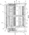
FIG. 1A is a front perspective view of a telecommunications cabinet including a universal equipment rack according to embodiments of the present invention. -
FIG. 1B is an enlarged perspective view of the telecommunications cabinet ofFIG. 1A . -
FIG. 2 is a perspective view of a structural rail for the universal equipment rack shown inFIG. 1A according to embodiments of the present invention. -
FIG. 3 is a perspective view of an insert plate for the universal equipment rack shown inFIG. 1A according to embodiments of the present invention. -
FIG. 4 is a rear perspective view of a bracket for the universal equipment rack shown inFIG. 1A . -
FIG. 5A is an enlarged view of the universal equipment rack mounted within a telecommunications cabinet according to embodiments of the present invention. -
FIG. 5B is a rear perspective view of the telecommunications cabinet with the universal equipment rack mounted therein according to embodiments of the present invention. -
FIG. 5C is an enlarged front perspective view of the telecommunications cabinet assembly ofFIG. 5B . -
FIG. 6 is a perspective view of a telecommunications cabinet with radios mounted to the equipment rack according to embodiments of the present invention. - The present invention now is described more fully hereinafter with reference to the accompanying drawings, in which embodiments of the invention are shown. This invention may, however, be embodied in many different forms and should not be construed as limited to the embodiments set forth herein; rather, these embodiments are provided so that this disclosure will be thorough and complete, and will fully convey the scope of the invention to those skilled in the art.
- Like numbers refer to like elements throughout. In the figures, the thickness of certain lines, layers, components, elements or features may be exaggerated for clarity.
- The terminology used herein is for the purpose of describing particular embodiments only and is not intended to be limiting of the invention. Unless otherwise defined, all terms (including technical and scientific terms) used herein have the same meaning as commonly understood by one of ordinary skill in the art to which this invention belongs. It will be further understood that terms, such as those defined in commonly used dictionaries, should be interpreted as having a meaning that is consistent with their meaning in the context of the specification and relevant art and should not be interpreted in an idealized or overly formal sense unless expressly so defined herein. Well-known functions or constructions may not be described in detail for brevity and/or clarity.
- As used herein, the singular forms "a", "an" and "the" are intended to include the plural forms as well, unless the context clearly indicates otherwise. It will be further understood that the terms "comprises" and/or "comprising," when used in this specification, specify the presence of stated features, integers, steps, operations, elements, and/or components, but do not preclude the presence or addition of one or more other features, integers, steps, operations, elements, components, and/or groups thereof. As used herein, the term "and/or" includes any and all combinations of one or more of the associated listed items.
- As used herein, phrases such as "between X and Y" and "between about X and Y" should be interpreted to include X and Y. As used herein, phrases such as "between about X and Y" mean "between about X and about Y." As used herein, phrases such as "from about X to Y" mean "from about X to about Y."
- It will be understood that when an element is referred to as being "on", "attached" to, "connected" to, "coupled" with, "contacting", etc., another element, it can be directly on, attached to, connected to, coupled with or contacting the other element or intervening elements may also be present. In contrast, when an element is referred to as being, for example, "directly on", "directly attached" to, "directly connected" to, "directly coupled" with or "directly contacting" another element, there are no intervening elements present. It will also be appreciated by those of skill in the art that references to a structure or feature that is disposed "adjacent" another feature may have portions that overlap or underlie the adjacent feature.
- Spatially relative terms, such as "under", "below", "lower", "over", "upper", "lateral", "left", "right" and the like, may be used herein for ease of description to describe one element or feature's relationship to another element(s) or feature(s) as illustrated in the figures. It will be understood that the spatially relative terms are intended to encompass different orientations of the device in use or operation in addition to the orientation depicted in the figures. For example, if the device in the figures is inverted, elements described as "under" or "beneath" other elements or features would then be oriented "over" the other elements or features. The device may be otherwise oriented (rotated 90 degrees or at other orientations) and the descriptors of relative spatial relationships used herein interpreted accordingly.
- Referring now to the figures, a telecommunications cabinet, designated broadly at 10, is illustrated in
FIGS. 1A-1B . Thecabinet 10 may be of conventional construction and need not be described in detail herein. In some embodiments, thecabinet 10 is designed around the standard 19" rack. In some embodiments, thecabinet 10 is generally box-shaped, with opposingside walls 13, aceiling 15, and afloor 16. In some embodiments, acenter support member 17 extends between theceiling 15 and thefloor 16 and divides thecabinet 10 into two approximately equal compartments orsections 14. Eachcompartment 14 of thecabinet 10 has a removablerear wall 19 which allows easy access to the back oftelecommunications equipment cabinet 10. Adoor 12 is pivotably coupled to eachside wall 13. In some embodiments, theside walls 13,doors 12, and/orrear walls 19 may compriseperforations 22 which allow air to circulate within thecabinet 10 to help preventtelecommunications equipment cabinet 10 from overheating (FIG. 6 ). - A vertical rail 20 (also seen in
FIGS. 1B ,5B , and5C ) is mounted to each of theside walls 13. Additionalvertical rails 21 are mounted to thecenter support member 17. As described in further detail below, thevertical rails equipment rack 30 according to embodiments of the present invention (i.e., mounting one or more equipment racks 30 within asection 14 of the cabinet 10). Thevertical rails cabinet 10. - Referring now to
FIGS. 2-4 , the components of theequipment rack 30 according to embodiments of the present invention are illustrated (see also, e.g.,FIGS. 5A-5C ). The components of theequipment rack 30 include a structural rail 40 (FIG. 2 ), an insert plate 50 (FIG. 3 ), and an equipment mounting bracket 60 (FIG. 4 ). Theequipment rack 30 of the present invention may be used with astandard telecommunication cabinet 10 described herein. In some embodiments, theequipment rack 30 may be used to mounttelecommunications equipment 90, 92 (e.g., passively cooled radios) within the cabinet 10 (see, e.g.,FIG. 6 ). Theequipment rack 30 of the present invention may allow atelecommunications cabinet 10 that has been deployed in the field to be reconfigured to acceptradio equipment radio equipment standard cabinet 10 that is configured to mount equipment horizontally within the cabinet 10 (i.e., stacking radios in a flat configuration) may be reconfigured by utilizing theequipment rack 30 of the present invention to allow the equipment to be vertically mounted within thecabinet 10. - The first component of the
equipment rack 30 of the present invention, i.e., thestructural rail 40, is shown inFIG. 2 . Thestructural rail 40 is generally rectangularly shaped, with amain body 41 and four walls (i.e., atop wall 42a, abottom wall 42b, and opposing side walls 43) that extend radially outwardly from themain body 41. The fourwalls 41 define acavity 44 that is sized and configured to receive an insert plate 50 (see, e.g.,FIG. 3 ). Eachside wall 43 comprises a plurality of mountingapertures 46 that allow thestructural rail 40 to be mounted and secured tovertical rails 20, 21 (e.g., via bolts) within thetelecommunications cabinet 10. - The
main body 41 of thestructural rail 40 comprises a series ofholes 45. As shown inFIG. 2 , in some embodiments, the series ofholes 45 are positioned longitudinally along a center axis A of thestructural rail 40. As discussed in further detail below, theholes 45 within themain body 41 provide location(s) to secure theinsert plate 50 to thestructural rail 40. As shown inFIG. 2 , in some embodiments, thestructural rail 40 may comprise eight (8) holes 45. In some embodiments, theholes 45 may be grouped into two sets of four (4) holes 45, with eachhole 45 in a set being separated by a distance of approximately 38 mm. In some embodiments, the two sets ofholes 45 may be spaced apart a distance of approximately 190 mm (i.e., the distance between the twoholes 45 closest to the center of the structural rail 40). - In some embodiments, the
main body 41 of thestructural rail 40 may also comprise two rows of elongate oroblong slots 47. Each row ofslots 47 may be positioned within themain body 41 adjacent to the top andbottom walls structural rail 41, respectively. As discussed in further detail below, theslots 47 within themain body 41 provide location(s) to secure the radio mount bracket 60 (seeFIG. 4 ) to thestructural rail 40 and also allow fordifferent insert plates 50 and brackets 60 (which correspond todifferent radio equipment 90, 92) to be used with thestructural rail 40. As shown inFIG. 2 , in some embodiments, each row may comprise twenty-one (21)slots 47. In some embodiments, eachadjacent slot 47 within a row may be separated by a distance of approximately 38 mm (measured to the center of each slot 47). Eachslot 47 may have a length of approximately 21.5 mm. - The second component of the
equipment rack 30 of the present invention, i.e., theinsert plate 50, is shown inFIG. 3 . Theinsert plate 50 is generally rectangularly shaped and is sized and configured to fit within thecavity 44 of thestructural rail 40. Theinsert plate 50 is specific to theradio equipment telecommunications cabinet 10, but is universal to thestructural rail 40. Theinsert plate 50 comprises a pair ofplate mounting holes 52 residing along a center axis of theinsert plate 50. Eachplate mounting hole 52 is positioned to align with arespective hole 45 in thestructural rail 40 such that theinsert plate 50 may be fastened to thestructural rail 40. - The
insert plate 50 further comprises a plurality of bracket mounting holes 54 (e.g., captive female threads). Thebracket mounting holes 54 are positioned adjacent to the top and bottom edges of theinsert plate 50 such that each of thebracket mounting holes 54 align with arespective slot 47 in themain body 41 of thestructural rail 40. As discussed in further detail below, when theinsert plate 50 is fastened to thestructural rail 40 via theplate mounting holes 52, each of thebracket mounting holes 54 will align within arespective slot 47 and are positioned in the exact location to provide the correct positioning and spacing for thecorresponding radio equipment 90, 92 (e.g., with the corresponding radio mount bracket 60) that will be mounted on theequipment rack 30 and within thetelecommunications cabinet 10. - The third component of the
equipment rack 30 of the present invention, i.e.,radio mounting bracket 60, is shown inFIG. 4 . Similar to theinsert plate 50, theradio mount bracket 60 is specific to theradio equipment telecommunications cabinet 10, but is universal to thestructural rail 40. As shown inFIG. 4 , thebracket 60 has amain body 62 with a pair offlanges 64 that extend radially outwardly from opposing sides of themain body 62. Themain body 62 has a plurality of mountingholes 67. The mounting holes 67 are configured such that thecorresponding radio equipment FIG. 6 ). - The
radio mounting bracket 60 includes a hangingmember 63 that extends radially outwardly from a top edge of themain body 62. The hangingmember 63 is configured engage thetop wall 42a of the structural rail 40 (e.g., viaflanged edge 63a) to provide additional structural support when the bracket 60 (andradio equipment 90, 92) is secured to the structural rail 40 (see, e.g.,FIG. 5A andFIG. 5C ). In some embodiments, thebracket 60 may further include asupport member 66 that extends radially outwardly from the bottom edge of themain body 62. Thesupport member 66 may help to position thebracket 60 flush against thestructural rail 40, thereby providing additional structural support to theradio mounting bracket 60. - Each
flange 64 has a pair of mountingholes 65. When thebracket 60 is placed on thestructural rail 40, each mountinghole 65 aligns with a correspondingbracket mounting hole 54 in the insert plate 50 (and aslot 47 in the structural rail 40). Theradio mounting bracket 60 may be secured to the insert plate 50 (and thus, the structural rail 40) via bolts through the mounting holes 65. Alignment of the mountingholes 65 of thebracket 60 with the respectivebracket mounting holes 54 of theinsert plate 50 position the radio mounting bracket(s) 60 in the exact location on thestructural rail 40, thereby allowing thecorresponding radio equipment telecommunications cabinet 10. - Referring to
FIGS. 5A-5C , a technician can reconfigure an existingtelecommunications cabinet 10 to allow the vertical mounting ofradio equipment telecommunications cabinet 10 by utilizing theequipment rack 30 of the present invention. - First, a universal
structural rail 40 is secured to thevertical rails telecommunications cabinet 10. Next, aninsert plate 50 corresponding to theradio equipment hole cavity 44 of thestructural rail 40. When theinsert plate 50 is mounted within thecavity 44 of thestructural rail 40, thebracket mounting holes 54 will align withrespective slots 47 in thestructural rail 40. Theinsert plate 50 is secured to thestructural rail 40 via fasteners (e.g., bolts) inserted through theplate mounting holes 52 ofinsert plate 50 and received through correspondingholes 45 of thestructural rail 40. - Next, each
radio mounting bracket 60 may be secured to a respective piece ofradio equipment holes 67. The radio mounting bracket 60 (andmounted radio equipment 90, 92) may then be mounted onto thestructural rail 40 by utilizing the hangingmember 63 which engages thetop wall 42a of thestructural rail 40 viaflanged edge 63a. The hangingmember 63 is configured to support the weight of theradio equipment bracket 60 andradio equipment structural rail 40. This allows the technician to slide the bracket 60 (andmounted radio equipment 90, 92) along thetop wall 42a of thestructural rail 40 until the mountingholes 65 in theflanges 64 of theradio mounting bracket 60 align withbracket mounting holes 54 of theinsert plate 50. This allows the technician to easily position the bracket 60 (andradio equipment 90, 92) on thestructural rail 40 without having to continuously hold theheavy radio equipment - Once the mounting
holes 66 of thebracket 60 are aligned with mountingholes 54 of theinsert plate 50, the bracket 60 (andcorresponding radio equipment 90, 92) may be secured to theequipment rack 30 via fasteners (e.g., bolts) inserted through thebracket mounting holes 54 of the insert plate 50 (andrespective slots 47 of the structural rail 40) and received through correspondingholes 65 in theradio mounting bracket 60.Additional radio equipment telecommunications cabinet 10 in the same manner with alignment of the respective mountingholes corresponding radio equipment cabinet 10. - As shown in
FIG. 6 , theequipment rack 30 of the present invention allows for different sizes and/or types ofradio equipment standard telecommunications cabinet 10. Exemplary radios that may be mounted utilizing theequipment rack 30 of the present invention may include, but are not limited to, Ericsson 4415, Ericsson 2238, Ericsson 4480, Ericsson 2460, Ericson 2012, Nokia AHPMDA, Nokia FZNJ, Nokia AZNC, and Huawei RRU5301. - The foregoing is illustrative of the present invention and is not to be construed as limiting thereof. Although a few exemplary embodiments of this invention have been described, those skilled in the art will readily appreciate that many modifications are possible in the exemplary embodiments without materially departing from the novel teachings and advantages of this invention. Accordingly, all such modifications are intended to be included within the scope of this invention as defined in the claims. The invention is defined by the following claims, with equivalents of the claims to be included therein.
- Further aspects of the disclosure may be summarized as follows:
- 1. An equipment rack for a telecommunications cabinet, comprising:
- a structural rail configured to be mounted within the telecommunications cabinet, the structural rail having a main body and four walls extending outwardly from the main body to define a cavity, wherein the main body comprises a plurality of holes and/or slots;
- an insert plate comprising one or more plate mounting holes and a plurality of bracket mounting holes, wherein the insert plate is configured to fit within the cavity of the structural rail and secured to the structural rail via fasteners through the plate mounting holes; and
- a bracket having a main body comprising a plurality of mounting holes, wherein the bracket is configured to be secured to the insert plate via fasteners when one or more of the mounting holes of the bracket are aligned with respective bracket mounting holes of the insert plate, and wherein the bracket is configured such that a piece of telecommunications equipment can be mounted thereto.
- 2. The equipment rack of Aspect 1, wherein the plurality of holes of the structural rail are positioned longitudinally along a center axis of the structural rail.
- 3. The equipment rack of any one of Aspects 1 or 2, wherein the structural rail comprises eight holes grouped into two sets of four holes with each hole in a set being spaced apart a distance of approximately 38 mm.
- 4. The equipment rack of any one of the preceding Aspects, in particular Aspect 3, wherein the two sets of four holes are spaced apart a distance of approximately 190 mm.
- 5. The equipment rack of any of the preceding aspects, wherein the structural rail comprises two rows of slots, each row of slots positioned with the main body of the structural rail adjacent to a top and bottom wall.
- 6. The equipment rack of any one of the preceding Aspects, in particular Aspect 5, wherein each row of slots comprises twenty-one slots, each adjacent slot being spaced apart a distance of approximately 38 mm measured to the center of each slot.
- 7. The equipment rack of any one of the preceding Aspects, in particular Aspect 2, wherein the one or more plate mounting holes reside along a center axis of the insert plate and align with a respective hole within the structural rail.
- 8. The equipment rack of any one of the preceding aspects, wherein the bracket mounting holes of the insert plate are captive female threads.
- 9. The equipment rack of any one of the preceding aspects, wherein the bracket mounting holes of the insert plate are positioned adjacent to a top edge and a bottom edge of the insert plate such that each bracket mounting hole aligns with a respective slot in the main body of the structural rail.
- 10. The equipment rack of any one of preceding aspects, wherein the bracket further comprises a pair of flanges extending radially outwardly from opposing sides of the main body, each flange comprising a pair of mounting holes, the pair of mounting holes configured to align with respective bracket mounting holes of the insert plate.
- 11. The equipment rack of any one of the preceding aspects, wherein the bracket further comprises a hanging member extending outwardly from the main body, the hanging member being configured to engage a top wall of the structural rail.
- 12. The equipment rack of any one of the preceding Aspects, in particular Aspect 11, wherein the hanging member is configured to overhang the top wall of the structural rail to allow the hanging member to slide along the top wall of the structural rail during installation.
- 13. The equipment rack of any one of the preceding aspects, wherein the bracket further comprises a support member extending radially outward from a bottom edge of the main body configured to position the bracket flush against the structural rail.
- 14. A telecommunications cabinet, comprising:
- a cabinet enclosure having two opposed side walls, a ceiling, a floor, and a center support member extending between the ceiling and the floor;
- a first vertical rail mounted to a side wall;
- a second vertical rail mounted to the center support member; and
- an equipment rack, the equipment rack comprising:
- a structural rail mounted to the first and second vertical rails, the structural rail having a main body and four walls extending outwardly from the main body to define a cavity, wherein the main body comprises a plurality of holes and/or slots;
- an insert plate comprising one or more plate mounting holes and a plurality of bracket mounting holes, wherein the insert plate is secured to the structural rail within the cavity of the structural rail via fasteners through the plate mounting holes; and
- a bracket having a main body comprising a plurality of mounting holes, wherein the bracket is secured to the to the insert plate via fasteners through one or more of the mounting holes of the bracket,
- wherein one or more pieces of telecommunications equipment is secured to the bracket and mounted vertically within the telecommunications cabinet.
- 15. The telecommunications cabinet of any one of the preceding Aspects, in
particular Aspect 14, wherein the structural rail of the equipment rack comprises eight holes grouped into two sets of four holes with each hole in a set being spaced apart a distance of approximately 38 mm. - 16. The telecommunications cabinet of any one of the preceding Aspects, in
particular Aspect 15, wherein the two sets of four holes within the structural rail are spaced apart a distance of approximately 190 mm. - 17. The telecommunications cabinet of any one of the preceding Aspects, in particular any one of Aspects 14-16, wherein the structural rail of the equipment rack comprises two rows of slots, each row of slots positioned with the main body of the structural rail adjacent to a top and bottom wall.
- 18. The telecommunications cabinet of any one of the preceding Aspects, in
particular Aspect 17, wherein each row of slots within the structural rail comprises twenty-one slots, each adjacent slot being spaced apart a distance of approximately 38 mm measured to the center of each slot. - 19. The telecommunications cabinet of any one of the preceding Aspects, in particular any one of Aspects 14-18, wherein the bracket mounting holes of the insert plate are positioned adjacent to a top edge and a bottom edge of the insert plate such that each bracket mounting hole aligns with a respective slot in the main body of the structural rail.
- 20. The telecommunications cabinet of any one of the preceding Aspects, in particular any one of Aspects 13-18, wherein the bracket of the equipment rack further comprises a pair of flanges extending radially outwardly from opposing sides of the main body, each flange comprising a pair of mounting holes, the pair of mounting holes configured to align with respective bracket mounting holes of the insert plate.
- 21. The telecommunications cabinet of any one of the preceding Aspects, in particular any one of Aspects 14-20, wherein the bracket of the equipment rack further comprises a hanging member extending outwardly from the main body, the hanging member engaged with a top wall of the structural rail.
- 22. The telecommunications cabinet of any one of the preceding Aspects, in
particular Aspect 21, wherein the hanging member is configured to overhang the top wall of the structural rail to allow the bracket to slide along the top wall of the structural rail during installation. - 23. A method of reconfiguring a telecommunications cabinet to allow vertical mounting of telecommunications equipment, the method comprising:
- providing a cabinet enclosure having two opposed side walls, a ceiling, a floor, and a center support member extending between the ceiling and the floor, a first vertical rail mounted to a side wall and a second vertical rail mounted to the center support member;
- providing an equipment rack including a structural rail having a main body and four walls extending outwardly from the main body to define a cavity, wherein the main body comprises a plurality of holes and/or slots, an insert plate comprising one or more plate mounting holes and a plurality of bracket mounting holes, and a bracket having a main body comprising a plurality of mounting holes and a hanging member extending outwardly from the main body;
- securing the side walls of the structural rail of the equipment rack to the first and second vertical rails;
- inserting the insert plate into the cavity of the structural rail such that the plate mounting holes of the insert plate align with one or more holes of the structural rail and the bracket mounting holes of the insert plate align with respective slots of the structural rail;
- securing the insert plate to the structural rail via fasteners through the plate mounting holes of the insert plate and received through the corresponding holes in the structural rail;
- securing the bracket of the equipment rack to a piece of telecommunications equipment;
- mounting the bracket and telecommunications equipment onto the structural rail by engaging the hanging member with a top wall of the structural rail;
- sliding the bracket along the top wall of the structural rail until the mounting holes of the bracket align with the bracket mounting holes of the insert plate; and
- securing the bracket to the insert plate and structural rail via fasteners, thereby securing the telecommunications equipment to the equipment rack with the telecommunications cabinet.
- 24. The method of any one of the preceding Aspects, in particular Aspect 23, wherein the hanging member overhangs the top wall of the structural rail to allow the bracket to slide along the top wall of the structural rail.
Claims (15)
- An equipment rack for a telecommunications cabinet, comprising:a structural rail configured to be mounted within the telecommunications cabinet, the structural rail having a main body and four walls extending outwardly from the main body to define a cavity, wherein the main body comprises a plurality of holes and/or slots;an insert plate comprising one or more plate mounting holes and a plurality of bracket mounting holes, wherein the insert plate is configured to fit within the cavity of the structural rail and secured to the structural rail via fasteners through the plate mounting holes; anda bracket having a main body comprising a plurality of mounting holes, wherein the bracket is configured to be secured to the insert plate via fasteners when one or more of the mounting holes of the bracket are aligned with respective bracket mounting holes of the insert plate, and wherein the bracket is configured such that a piece of telecommunications equipment can be mounted thereto.
- The equipment rack of Claim 1, wherein the plurality of holes of the structural rail are positioned longitudinally along a center axis of the structural rail.
- The equipment rack of any one of Claims 1 or 2, wherein the structural rail comprises eight holes grouped into two sets of four holes with each hole in a set being spaced apart a distance of approximately 38 mm.
- The equipment rack of Claim 3, wherein the two sets of four holes are spaced apart a distance of approximately 190 mm.
- The equipment rack of any of the preceding claims, wherein the structural rail comprises two rows of slots, each row of slots positioned with the main body of the structural rail adjacent to a top and bottom wall.
- The equipment rack of Claim 5, wherein each row of slots comprises twenty-one slots, each adjacent slot being spaced apart a distance of approximately 38 mm measured to the center of each slot.
- The equipment rack of any of the preceding claims, in particular Claim 2, wherein the one or more plate mounting holes reside along a center axis of the insert plate and align with a respective hole within the structural rail.
- The equipment rack of any one of the preceding claims, wherein the bracket mounting holes of the insert plate are captive female threads.
- The equipment rack of any one of the preceding claims, wherein the bracket mounting holes of the insert plate are positioned adjacent to a top edge and a bottom edge of the insert plate such that each bracket mounting hole aligns with a respective slot in the main body of the structural rail.
- The equipment rack of any one of preceding claims, wherein the bracket further comprises a pair of flanges extending radially outwardly from opposing sides of the main body, each flange comprising a pair of mounting holes, the pair of mounting holes configured to align with respective bracket mounting holes of the insert plate.
- The equipment rack of any one of the preceding claims, wherein the bracket further comprises a hanging member extending outwardly from the main body, the hanging member being configured to engage a top wall of the structural rail.
- The equipment rack of Claim 11, wherein the hanging member is configured to overhang the top wall of the structural rail to allow the hanging member to slide along the top wall of the structural rail during installation.
- The equipment rack of any one of the preceding claims, wherein the bracket further comprises a support member extending radially outward from a bottom edge of the main body configured to position the bracket flush against the structural rail.
- The equipment rack of any one of the preceding claims, in combination with telecommunications a cabinet enclosure having two opposed side walls, a ceiling, a floor, and a center support member extending between the ceiling and the floor, wherein one or more pieces of telecommunications equipment is secured to the bracket and mounted vertically within the telecommunications cabinet.
- A method of reconfiguring a telecommunications cabinet to allow vertical mounting of telecommunications equipment, the method comprising:providing a cabinet enclosure having two opposed side walls, a ceiling, a floor, and a center support member extending between the ceiling and the floor, a first vertical rail mounted to a side wall and a second vertical rail mounted to the center support member;providing an equipment rack according to Claim 1;securing the side walls of the structural rail of the equipment rack to the first and second vertical rails;inserting the insert plate into the cavity of the structural rail such that the plate mounting holes of the insert plate align with one or more holes of the structural rail and the bracket mounting holes of the insert plate align with respective slots of the structural rail;securing the insert plate to the structural rail via fasteners through the plate mounting holes of the insert plate and received through the corresponding holes in the structural rail;securing the bracket of the equipment rack to a piece of telecommunications equipment;mounting the bracket and telecommunications equipment onto the structural rail by engaging the hanging member with a top wall of the structural rail;sliding the bracket along the top wall of the structural rail until the mounting holes of the bracket align with the bracket mounting holes of the insert plate; andsecuring the bracket to the insert plate and structural rail via fasteners, thereby securing the telecommunications equipment to the equipment rack with the telecommunications cabinet.
Applications Claiming Priority (1)
| Application Number | Priority Date | Filing Date | Title |
|---|---|---|---|
| US202063115088P | 2020-11-18 | 2020-11-18 |
Publications (2)
| Publication Number | Publication Date |
|---|---|
| EP4002969A1 true EP4002969A1 (en) | 2022-05-25 |
| EP4002969B1 EP4002969B1 (en) | 2024-10-23 |
Family
ID=78676312
Family Applications (1)
| Application Number | Title | Priority Date | Filing Date |
|---|---|---|---|
| EP21208444.6A Active EP4002969B1 (en) | 2020-11-18 | 2021-11-16 | Universal equipment rack for telecommunications cabinets |
Country Status (2)
| Country | Link |
|---|---|
| US (1) | US11765854B2 (en) |
| EP (1) | EP4002969B1 (en) |
Cited By (1)
| Publication number | Priority date | Publication date | Assignee | Title |
|---|---|---|---|---|
| US11765854B2 (en) * | 2020-11-18 | 2023-09-19 | Commscope Technologies Llc | Universal equipment rack for telecommunications cabinets |
Families Citing this family (1)
| Publication number | Priority date | Publication date | Assignee | Title |
|---|---|---|---|---|
| CN115052453B (en) * | 2022-06-28 | 2023-06-13 | 中车株洲电力机车有限公司 | Sliding rail cabinet |
Citations (3)
| Publication number | Priority date | Publication date | Assignee | Title |
|---|---|---|---|---|
| US6769551B2 (en) * | 2002-07-26 | 2004-08-03 | Dell Products L.P. | System and method for utilizing non-dedicated rack space |
| US20170280580A1 (en) * | 2016-03-22 | 2017-09-28 | Commscope Technologies Llc | Adjustable rack for electronics cabinet |
| US10743437B2 (en) * | 2014-04-30 | 2020-08-11 | Telefonaktiebolaget Lm Ericsson (Publ) | Mounting of a telecommunication equipment to a structure |
Family Cites Families (17)
| Publication number | Priority date | Publication date | Assignee | Title |
|---|---|---|---|---|
| US4002969A (en) * | 1976-01-26 | 1977-01-11 | The United States Of America As Represented By The Secretary Of The Army | Optimum length transmission line discriminator with low noise detector |
| US5593115A (en) * | 1994-06-15 | 1997-01-14 | Lewis; James M. | Pipe hanger |
| US6079677A (en) * | 1998-03-13 | 2000-06-27 | Lucent Technologies Inc. | Adjustable bracket assembly for a building entrance box |
| US6666419B1 (en) * | 1999-11-23 | 2003-12-23 | 3244 Corporation | Bracket assembly for mounting electrical box between two building studs |
| US7472875B2 (en) * | 2005-03-29 | 2009-01-06 | Cooper Technologies Company | Bracket for mounting an electrical device |
| TWM296940U (en) * | 2006-04-19 | 2006-09-01 | Ming-Hsien Huang | Hanging device for hanging electronic device on vertical wall |
| FI7697U1 (en) * | 2007-06-15 | 2007-11-30 | Abb Oy | Reinforcement beams for an electronics cabinet |
| US8215597B1 (en) * | 2008-07-14 | 2012-07-10 | Medlin Sr Lewis B | Electrical box support tab construction |
| CN102340950A (en) * | 2010-07-26 | 2012-02-01 | 鸿富锦精密工业(深圳)有限公司 | Server cabinet framework |
| TWI448262B (en) * | 2010-10-11 | 2014-08-11 | King Slide Works Co Ltd | Slide rail with reinforced structure |
| CN103677149A (en) * | 2012-09-14 | 2014-03-26 | 鸿富锦精密工业(深圳)有限公司 | fan mount |
| US9568140B2 (en) * | 2014-09-19 | 2017-02-14 | First Base Inc | Adapter plate for connecting two monitors to an arm mount |
| CA2950839C (en) * | 2016-01-30 | 2023-09-12 | Cooper Technologies Company | Equipment rack and components thereof |
| SG11202103760RA (en) * | 2018-11-15 | 2021-05-28 | Cfw Invest Llc | Modular rack assembly |
| US10716235B1 (en) * | 2019-02-01 | 2020-07-14 | Cisco Technology, Inc. | Adjustable mounting rail latches |
| CN209929795U (en) * | 2019-05-31 | 2020-01-10 | 四川晨龙航天电器设备有限公司 | Novel ventilation type reactive compensation cabinet |
| US11765854B2 (en) * | 2020-11-18 | 2023-09-19 | Commscope Technologies Llc | Universal equipment rack for telecommunications cabinets |
-
2021
- 2021-11-09 US US17/522,154 patent/US11765854B2/en active Active
- 2021-11-16 EP EP21208444.6A patent/EP4002969B1/en active Active
Patent Citations (3)
| Publication number | Priority date | Publication date | Assignee | Title |
|---|---|---|---|---|
| US6769551B2 (en) * | 2002-07-26 | 2004-08-03 | Dell Products L.P. | System and method for utilizing non-dedicated rack space |
| US10743437B2 (en) * | 2014-04-30 | 2020-08-11 | Telefonaktiebolaget Lm Ericsson (Publ) | Mounting of a telecommunication equipment to a structure |
| US20170280580A1 (en) * | 2016-03-22 | 2017-09-28 | Commscope Technologies Llc | Adjustable rack for electronics cabinet |
Cited By (1)
| Publication number | Priority date | Publication date | Assignee | Title |
|---|---|---|---|---|
| US11765854B2 (en) * | 2020-11-18 | 2023-09-19 | Commscope Technologies Llc | Universal equipment rack for telecommunications cabinets |
Also Published As
| Publication number | Publication date |
|---|---|
| EP4002969B1 (en) | 2024-10-23 |
| US20220159866A1 (en) | 2022-05-19 |
| US11765854B2 (en) | 2023-09-19 |
Similar Documents
| Publication | Publication Date | Title |
|---|---|---|
| US10349553B2 (en) | Adjustable rack for electronics cabinet | |
| US20100110621A1 (en) | Rack with vertical mounting providing room for rack pdu | |
| RU2562797C2 (en) | System and method for installation of devices of 1u-tuple height without using tools | |
| US10588227B2 (en) | Vertical mounting rail with cable management features | |
| US11765854B2 (en) | Universal equipment rack for telecommunications cabinets | |
| US9755200B2 (en) | Equipment cabinet | |
| US20200053903A1 (en) | Method for integrating a building block framework assembly for data center racks | |
| US9131769B2 (en) | Open bridge rack | |
| US10283983B2 (en) | Repositionable shelf system for device charging and storage cabinets or carts | |
| US10172453B1 (en) | System equipment carriers and related methods | |
| US10104799B2 (en) | Network element chassis tool and method for single person installation | |
| US6429376B1 (en) | Add-on trough for cable management rack | |
| CA2602333A1 (en) | Field convertible telecommunications distribution pedestal | |
| US7239523B1 (en) | Electronic assembly with modular midplane | |
| US8833711B2 (en) | Two post rack with floor mounting brackets | |
| US20120019111A1 (en) | Modular Equipment Enclosure | |
| US20170346054A1 (en) | Electrical equipment cabinets with one or more battery unifying carriers | |
| US10798845B2 (en) | 1U rackmount enclosure and 1U rack | |
| US20090065669A1 (en) | Pole mounting systems and methods | |
| US20050174741A1 (en) | Assembly for installation of power electronics modules and installation method | |
| US12342495B2 (en) | Electronics enclosure with extendable equipment mounts | |
| US20170295665A1 (en) | Pre-terminated overvoltage protection module for electronics cabinet | |
| US11019741B2 (en) | Apparatus for protecting telecommunication radios and methods of using the same | |
| CN209994741U (en) | Network cabinet | |
| CN210694556U (en) | Integrated multi-box integrated cabinet |
Legal Events
| Date | Code | Title | Description |
|---|---|---|---|
| PUAI | Public reference made under article 153(3) epc to a published international application that has entered the european phase |
Free format text: ORIGINAL CODE: 0009012 |
|
| STAA | Information on the status of an ep patent application or granted ep patent |
Free format text: STATUS: REQUEST FOR EXAMINATION WAS MADE |
|
| 17P | Request for examination filed |
Effective date: 20211116 |
|
| AK | Designated contracting states |
Kind code of ref document: A1 Designated state(s): AL AT BE BG CH CY CZ DE DK EE ES FI FR GB GR HR HU IE IS IT LI LT LU LV MC MK MT NL NO PL PT RO RS SE SI SK SM TR |
|
| GRAP | Despatch of communication of intention to grant a patent |
Free format text: ORIGINAL CODE: EPIDOSNIGR1 |
|
| STAA | Information on the status of an ep patent application or granted ep patent |
Free format text: STATUS: GRANT OF PATENT IS INTENDED |
|
| INTG | Intention to grant announced |
Effective date: 20240514 |
|
| GRAS | Grant fee paid |
Free format text: ORIGINAL CODE: EPIDOSNIGR3 |
|
| GRAA | (expected) grant |
Free format text: ORIGINAL CODE: 0009210 |
|
| STAA | Information on the status of an ep patent application or granted ep patent |
Free format text: STATUS: THE PATENT HAS BEEN GRANTED |
|
| RAP1 | Party data changed (applicant data changed or rights of an application transferred) |
Owner name: COMMSCOPE TECHNOLOGIES LLC |
|
| RAP1 | Party data changed (applicant data changed or rights of an application transferred) |
Owner name: OUTDOOR WIRELESS NETWORKS LLC |
|
| AK | Designated contracting states |
Kind code of ref document: B1 Designated state(s): AL AT BE BG CH CY CZ DE DK EE ES FI FR GB GR HR HU IE IS IT LI LT LU LV MC MK MT NL NO PL PT RO RS SE SI SK SM TR |
|
| REG | Reference to a national code |
Ref country code: GB Ref legal event code: FG4D |
|
| REG | Reference to a national code |
Ref country code: CH Ref legal event code: EP |
|
| REG | Reference to a national code |
Ref country code: DE Ref legal event code: R096 Ref document number: 602021020595 Country of ref document: DE |
|
| REG | Reference to a national code |
Ref country code: IE Ref legal event code: FG4D |
|
| REG | Reference to a national code |
Ref country code: LT Ref legal event code: MG9D |
|
| REG | Reference to a national code |
Ref country code: NL Ref legal event code: MP Effective date: 20241023 |
|
| REG | Reference to a national code |
Ref country code: AT Ref legal event code: MK05 Ref document number: 1735928 Country of ref document: AT Kind code of ref document: T Effective date: 20241023 |
|
| PG25 | Lapsed in a contracting state [announced via postgrant information from national office to epo] |
Ref country code: NL Free format text: LAPSE BECAUSE OF FAILURE TO SUBMIT A TRANSLATION OF THE DESCRIPTION OR TO PAY THE FEE WITHIN THE PRESCRIBED TIME-LIMIT Effective date: 20241023 |
|
| PG25 | Lapsed in a contracting state [announced via postgrant information from national office to epo] |
Ref country code: NL Free format text: LAPSE BECAUSE OF FAILURE TO SUBMIT A TRANSLATION OF THE DESCRIPTION OR TO PAY THE FEE WITHIN THE PRESCRIBED TIME-LIMIT Effective date: 20241023 |
|
| PG25 | Lapsed in a contracting state [announced via postgrant information from national office to epo] |
Ref country code: PT Free format text: LAPSE BECAUSE OF FAILURE TO SUBMIT A TRANSLATION OF THE DESCRIPTION OR TO PAY THE FEE WITHIN THE PRESCRIBED TIME-LIMIT Effective date: 20250224 Ref country code: HR Free format text: LAPSE BECAUSE OF FAILURE TO SUBMIT A TRANSLATION OF THE DESCRIPTION OR TO PAY THE FEE WITHIN THE PRESCRIBED TIME-LIMIT Effective date: 20241023 Ref country code: IS Free format text: LAPSE BECAUSE OF FAILURE TO SUBMIT A TRANSLATION OF THE DESCRIPTION OR TO PAY THE FEE WITHIN THE PRESCRIBED TIME-LIMIT Effective date: 20250223 |
|
| PG25 | Lapsed in a contracting state [announced via postgrant information from national office to epo] |
Ref country code: FI Free format text: LAPSE BECAUSE OF FAILURE TO SUBMIT A TRANSLATION OF THE DESCRIPTION OR TO PAY THE FEE WITHIN THE PRESCRIBED TIME-LIMIT Effective date: 20241023 |
|
| PG25 | Lapsed in a contracting state [announced via postgrant information from national office to epo] |
Ref country code: BG Free format text: LAPSE BECAUSE OF FAILURE TO SUBMIT A TRANSLATION OF THE DESCRIPTION OR TO PAY THE FEE WITHIN THE PRESCRIBED TIME-LIMIT Effective date: 20241023 |
|
| PG25 | Lapsed in a contracting state [announced via postgrant information from national office to epo] |
Ref country code: ES Free format text: LAPSE BECAUSE OF FAILURE TO SUBMIT A TRANSLATION OF THE DESCRIPTION OR TO PAY THE FEE WITHIN THE PRESCRIBED TIME-LIMIT Effective date: 20241023 |
|
| PG25 | Lapsed in a contracting state [announced via postgrant information from national office to epo] |
Ref country code: NO Free format text: LAPSE BECAUSE OF FAILURE TO SUBMIT A TRANSLATION OF THE DESCRIPTION OR TO PAY THE FEE WITHIN THE PRESCRIBED TIME-LIMIT Effective date: 20250123 |
|
| PG25 | Lapsed in a contracting state [announced via postgrant information from national office to epo] |
Ref country code: LV Free format text: LAPSE BECAUSE OF FAILURE TO SUBMIT A TRANSLATION OF THE DESCRIPTION OR TO PAY THE FEE WITHIN THE PRESCRIBED TIME-LIMIT Effective date: 20241023 Ref country code: AT Free format text: LAPSE BECAUSE OF FAILURE TO SUBMIT A TRANSLATION OF THE DESCRIPTION OR TO PAY THE FEE WITHIN THE PRESCRIBED TIME-LIMIT Effective date: 20241023 Ref country code: GR Free format text: LAPSE BECAUSE OF FAILURE TO SUBMIT A TRANSLATION OF THE DESCRIPTION OR TO PAY THE FEE WITHIN THE PRESCRIBED TIME-LIMIT Effective date: 20250124 |
|
| PG25 | Lapsed in a contracting state [announced via postgrant information from national office to epo] |
Ref country code: PL Free format text: LAPSE BECAUSE OF FAILURE TO SUBMIT A TRANSLATION OF THE DESCRIPTION OR TO PAY THE FEE WITHIN THE PRESCRIBED TIME-LIMIT Effective date: 20241023 |
|
| PG25 | Lapsed in a contracting state [announced via postgrant information from national office to epo] |
Ref country code: RS Free format text: LAPSE BECAUSE OF FAILURE TO SUBMIT A TRANSLATION OF THE DESCRIPTION OR TO PAY THE FEE WITHIN THE PRESCRIBED TIME-LIMIT Effective date: 20250123 |
|
| REG | Reference to a national code |
Ref country code: DE Ref legal event code: R119 Ref document number: 602021020595 Country of ref document: DE |
|
| REG | Reference to a national code |
Ref country code: CH Ref legal event code: PL |
|
| PG25 | Lapsed in a contracting state [announced via postgrant information from national office to epo] |
Ref country code: SM Free format text: LAPSE BECAUSE OF FAILURE TO SUBMIT A TRANSLATION OF THE DESCRIPTION OR TO PAY THE FEE WITHIN THE PRESCRIBED TIME-LIMIT Effective date: 20241023 |
|
| PG25 | Lapsed in a contracting state [announced via postgrant information from national office to epo] |
Ref country code: MC Free format text: LAPSE BECAUSE OF FAILURE TO SUBMIT A TRANSLATION OF THE DESCRIPTION OR TO PAY THE FEE WITHIN THE PRESCRIBED TIME-LIMIT Effective date: 20241023 |
|
| PG25 | Lapsed in a contracting state [announced via postgrant information from national office to epo] |
Ref country code: DK Free format text: LAPSE BECAUSE OF FAILURE TO SUBMIT A TRANSLATION OF THE DESCRIPTION OR TO PAY THE FEE WITHIN THE PRESCRIBED TIME-LIMIT Effective date: 20241023 |
|
| PG25 | Lapsed in a contracting state [announced via postgrant information from national office to epo] |
Ref country code: LU Free format text: LAPSE BECAUSE OF NON-PAYMENT OF DUE FEES Effective date: 20241116 |
|
| REG | Reference to a national code |
Ref country code: CH Ref legal event code: PL |
|
| PG25 | Lapsed in a contracting state [announced via postgrant information from national office to epo] |
Ref country code: EE Free format text: LAPSE BECAUSE OF FAILURE TO SUBMIT A TRANSLATION OF THE DESCRIPTION OR TO PAY THE FEE WITHIN THE PRESCRIBED TIME-LIMIT Effective date: 20241023 |
|
| PG25 | Lapsed in a contracting state [announced via postgrant information from national office to epo] |
Ref country code: CH Free format text: LAPSE BECAUSE OF NON-PAYMENT OF DUE FEES Effective date: 20241130 |
|
| PG25 | Lapsed in a contracting state [announced via postgrant information from national office to epo] |
Ref country code: RO Free format text: LAPSE BECAUSE OF FAILURE TO SUBMIT A TRANSLATION OF THE DESCRIPTION OR TO PAY THE FEE WITHIN THE PRESCRIBED TIME-LIMIT Effective date: 20241023 |
|
| PG25 | Lapsed in a contracting state [announced via postgrant information from national office to epo] |
Ref country code: SK Free format text: LAPSE BECAUSE OF FAILURE TO SUBMIT A TRANSLATION OF THE DESCRIPTION OR TO PAY THE FEE WITHIN THE PRESCRIBED TIME-LIMIT Effective date: 20241023 |
|
| PG25 | Lapsed in a contracting state [announced via postgrant information from national office to epo] |
Ref country code: CZ Free format text: LAPSE BECAUSE OF FAILURE TO SUBMIT A TRANSLATION OF THE DESCRIPTION OR TO PAY THE FEE WITHIN THE PRESCRIBED TIME-LIMIT Effective date: 20241023 |
|
| PG25 | Lapsed in a contracting state [announced via postgrant information from national office to epo] |
Ref country code: IT Free format text: LAPSE BECAUSE OF FAILURE TO SUBMIT A TRANSLATION OF THE DESCRIPTION OR TO PAY THE FEE WITHIN THE PRESCRIBED TIME-LIMIT Effective date: 20241023 |
|
| REG | Reference to a national code |
Ref country code: BE Ref legal event code: MM Effective date: 20241130 |
|
| PLBE | No opposition filed within time limit |
Free format text: ORIGINAL CODE: 0009261 |
|
| STAA | Information on the status of an ep patent application or granted ep patent |
Free format text: STATUS: NO OPPOSITION FILED WITHIN TIME LIMIT |
|
| PG25 | Lapsed in a contracting state [announced via postgrant information from national office to epo] |
Ref country code: SE Free format text: LAPSE BECAUSE OF FAILURE TO SUBMIT A TRANSLATION OF THE DESCRIPTION OR TO PAY THE FEE WITHIN THE PRESCRIBED TIME-LIMIT Effective date: 20241023 |
|
| 26N | No opposition filed |
Effective date: 20250724 |
|
| PG25 | Lapsed in a contracting state [announced via postgrant information from national office to epo] |
Ref country code: DE Free format text: LAPSE BECAUSE OF NON-PAYMENT OF DUE FEES Effective date: 20250603 |
|
| PG25 | Lapsed in a contracting state [announced via postgrant information from national office to epo] |
Ref country code: BE Free format text: LAPSE BECAUSE OF NON-PAYMENT OF DUE FEES Effective date: 20241130 |
|
| PG25 | Lapsed in a contracting state [announced via postgrant information from national office to epo] |
Ref country code: FR Free format text: LAPSE BECAUSE OF NON-PAYMENT OF DUE FEES Effective date: 20241223 |
|
| PG25 | Lapsed in a contracting state [announced via postgrant information from national office to epo] |
Ref country code: IE Free format text: LAPSE BECAUSE OF NON-PAYMENT OF DUE FEES Effective date: 20241116 |
|
| PGFP | Annual fee paid to national office [announced via postgrant information from national office to epo] |
Ref country code: GB Payment date: 20251127 Year of fee payment: 5 |
|
| PG25 | Lapsed in a contracting state [announced via postgrant information from national office to epo] |
Ref country code: HU Free format text: LAPSE BECAUSE OF FAILURE TO SUBMIT A TRANSLATION OF THE DESCRIPTION OR TO PAY THE FEE WITHIN THE PRESCRIBED TIME-LIMIT; INVALID AB INITIO Effective date: 20211116 |
|
| PG25 | Lapsed in a contracting state [announced via postgrant information from national office to epo] |
Ref country code: CY Free format text: LAPSE BECAUSE OF FAILURE TO SUBMIT A TRANSLATION OF THE DESCRIPTION OR TO PAY THE FEE WITHIN THE PRESCRIBED TIME-LIMIT; INVALID AB INITIO Effective date: 20211116 |