EP2053715B1 - Cable pathway system - Google Patents
Cable pathway system Download PDFInfo
- Publication number
- EP2053715B1 EP2053715B1 EP08253388.6A EP08253388A EP2053715B1 EP 2053715 B1 EP2053715 B1 EP 2053715B1 EP 08253388 A EP08253388 A EP 08253388A EP 2053715 B1 EP2053715 B1 EP 2053715B1
- Authority
- EP
- European Patent Office
- Prior art keywords
- base
- cable pathway
- cable
- top surface
- apertures
- Prior art date
- Legal status (The legal status is an assumption and is not a legal conclusion. Google has not performed a legal analysis and makes no representation as to the accuracy of the status listed.)
- Active
Links
Images


Classifications
-
- H—ELECTRICITY
- H02—GENERATION; CONVERSION OR DISTRIBUTION OF ELECTRIC POWER
- H02G—INSTALLATION OF ELECTRIC CABLES OR LINES, OR OF COMBINED OPTICAL AND ELECTRIC CABLES OR LINES
- H02G3/00—Installations of electric cables or lines or protective tubing therefor in or on buildings, equivalent structures or vehicles
- H02G3/30—Installations of cables or lines on walls, floors or ceilings
-
- Y—GENERAL TAGGING OF NEW TECHNOLOGICAL DEVELOPMENTS; GENERAL TAGGING OF CROSS-SECTIONAL TECHNOLOGIES SPANNING OVER SEVERAL SECTIONS OF THE IPC; TECHNICAL SUBJECTS COVERED BY FORMER USPC CROSS-REFERENCE ART COLLECTIONS [XRACs] AND DIGESTS
- Y10—TECHNICAL SUBJECTS COVERED BY FORMER USPC
- Y10T—TECHNICAL SUBJECTS COVERED BY FORMER US CLASSIFICATION
- Y10T29/00—Metal working
- Y10T29/49—Method of mechanical manufacture
- Y10T29/49826—Assembling or joining
Definitions
- This invention relates to cable pathway systems and, more particularly, to cable pathway systems used in association with electronic equipment cabinets to form a pathway for cables which enter and exit the electronic equipment cabinets.
- typical cable pathway systems employ ladder racks or wire frame baskets. These racks and baskets are suspended from the ceiling by threaded rods embedded in the ceiling and may require additional time and/or labor to install. In addition, once these racks or baskets are installed, it is difficult to change or reconfigure the cable pathway systems without substantial labor. Furthermore, as the cooling requirements of data centers increase the height of the raised floor increases, thereby decreasing the clearance available between the top of the electronic equipment enclosures and the ceiling, making installation of these pathways even more difficult.
- Patent Application US 2003/0051892 discloses a cable channel assembly comprising a segment to be attached to cable raceway for permitting cables to pass between the cable raceway and the cable channel segment.
- the segment provides a set of apertures having adjacent walls comprising curved surfaces.
- US Patent 6,586,680 proposes a fixture to be attached to a cable pathway having walls with curved surfaces.
- US Patent 5,969,292 discloses a cable pathway system configured to engage a top cover of an electronic equipment enclosure.
- a cable pathway system is provided as defined in independent claim 1.
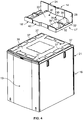
- cable pathway member 10 is shown in two sections 12 and 14, which when positioned adjacent to one another, form cable pathway member 10.
- Alternative examples could include pathway member 10 constructed of a single piece or even constructed of a greater number of sections than shown in Fig. 1 .
- cable pathway member 10 is in its proper configuration to carry various electronic cables and is sized to be positioned on a top of an electronic equipment enclosure 16.
- enclosure 16 is shown as a cabinet.
- enclosure 16 may be any number of structures such as a four post rack, a cable manager, a network cabinet, a server cabinet or any other structure designed to carry electronic equipment serviced by electronic power and/or communication cables.
- Cable pathway member 10 provides a pathway for positioning electronic cables along the top of an electronic equipment enclosure 16. With cable pathway 10 positioned on top of enclosure 16, installation and maintenance of the cables that service the electronic equipment disposed within the electronic equipment enclosure 16 is made easier and more convenient.
- each of sections 12 and 14 are constructed to be the same shape and size which provides for ease and convenience in manufacturing and in use. As a result, in this example each section will have the same corresponding part.
- Sections 12 and 14 each have a portion of a base 17' a bottom 18' and a generally planar top surface 20'.
- cable pathway member 10 is formed and a completed base 17, bottom 18, and generally planar top surface 20 are formed.
- a first side 22 and a second side 24 are provided on opposing sides of pathway member 10.
- First side 22 comprises a first sidewall 26 and second side 24 comprises second sidewall 28.
- First and second sidewalls 26 and 28 each extend generally perpendicular from top planar surface 20 and extend substantially along a length of their respective first and second sides 22 and 24. First and second sidewalls 26 and 28 provide lateral confinement for cables contained in pathway member 10. Moreover, cable pathway member 10 is sized such that first sidewall 26 generally aligns with a front side 19 of electronic equipment enclosure 16 and second sidewall 28 generally aligns with a back side 21 of electronic equipment enclosure 16.
- Cable pathway member 10 is configured to be secured to the top of cabinet 16 by providing, in this example, one or more holes 30 which pass through the base of each section 12 and 14. In positioning cable pathway member 10 on the top of electronic equipment enclosure 16, one or more of holes 30 are positioned to each align with a corresponding hole (not shown) in electronic equipment enclosure 16. A bolt or screw can be passed through a hole 30 and its corresponding aligned hole in enclosure 16 thereby allowing cable pathway member 10 to be secured via a nut or other fastener to electronic equipment enclosure 16.
- Cable pathway member 10 is generally constructed of a molded plastic or other non-metallic material.
- pathway member 10 is constructed of a molded plastic. Since pathway member 10 may be required to carry a substantial amount of cables and thereby a substantial amount of weight, it is desired that base 17 be constructed of a solid construction and/or be provided with strengthening ribs to reinforce the underside of base 17. To support the weight of the cables positioned within cable pathway member 10, it is also desirable to position portions of base 17 to overlie portions of electronic equipment enclosure 16 such that the portion of base 17 which carries a larger load receives underlying support from a support structure within enclosure 16. Providing such support will prevent pathway member 10 from sagging from larger cable loads.
- Base 17 of cable pathway member 10 defines at least one aperture 32 which passes from top surface 20 through bottom 18 of base 17.
- wall 36 Positioned adjacent to aperture 32 is wall 36, which comprises a curved surface 38 that extends from top surface 20 to bottom 18 of base 17.
- Wall 36 supports cables which overlie top surface 20 and extend into and out of electronic equipment enclosure 16 through aperture 32.
- the radius of curvature of wall 36 is generally 76.2 mm (3 inches), but can be configured with any appropriate radius of curvature that will provide a smooth transition of the change of direction of the cable.
- the cable is positioned to extend generally horizontal in cable pathway member 10 and then changes to extend generally vertical with the cable entering or exiting from enclosure 16. Curved surface 38 provides a smooth transition of the cable as it changes direction and preserves the integrity of the cable and reliability of transmission.
- a first set 31 of apertures 32 are positioned adjacent to and along a third side 25 of cable pathway member 10 and a second set 35 of apertures 32 are positioned adjacent to and along an opposing fourth side 27 of cable pathway member 10.
- each of these apertures 32 comprises a wall 36 with a curved surface 38 positioned adjacent to apertures 32.
- the radius of curvature of wall 36 is 76.2 mm (3 inches) but can be configured with a radius that will provide a smooth transition for the cable as it changes direction.
- first and second sets 31 and 35 of apertures 32 each form a row wherein, with cable pathway member 10 secured to enclosure 16, each aperture 32 is positioned to vertically align with an opening 37 positioned within top cover 39 of enclosure 16. With each aperture 32 vertically aligned with an opening 37, cables are easily positioned to extend into and out of enclosure 16 through top cover 39 and engage curved surface 38 to provide a smooth transition of the cable extending from inside of enclosure 16 to along top surface 20 of cable pathway member 10.
- sections 12 and 14 are positioned together to form cable pathway member 10.
- matching non-planar side surfaces 40 and 42 are provided on base 17' of each section 12 and 14 respectively.
- non-planar side surface 40 of section 12 is positioned on an opposite side of section 12 from sidewall 26 and similarly, non-planar side surface 42 of section 14 is positioned on an opposite side of section 14 from sidewall 28.
- Non-planar side surfaces 40 and 42 complement one another and form mating surfaces such that with sections 12 and 14 placed together, they form base 17.
- a protrusion 44 positioned in side surface 40 fitting into a recess 46 in side surface 42, relative movement between sections 12 and 14 along side surfaces 40 and 42 is prevented.
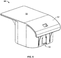
- Insert 48 is shown. Insert 48 is positionable into aperture 32, as seen in Fig. 7 , thereby blocking such aperture 32 and preventing cable from entering or exiting that aperture 32. As can be seen in Fig. 7 , in this example insert 48 has a size and shape such that one insert will prevent access to half of aperture 32, allowing more flexibility in the installation of the cable pathway system. However, instead of, or in addition to inserts 48, there could also be inserts that fill all of aperture 32 or that block any other fraction of aperture 32 desired. Insert 48 also provides a support surface for cables positioned in cable pathway member 10 and provides a top surface 50 which is generally planar and aligns generally with top planar surface 20 of base 17.
- Insert 48 also has curved surface 52 and, as described earlier for curved surface 38 positioned in cable pathway member 10, curved surface 52 comprises a radius of curvature of 76.2 mm (3 inches). As discussed above for curved surface 38, curved surface 52 can be configured with any radius of curvature that will provide a smooth transition of direction for cable positioned generally horizontal in cable member pathway 10 to a generally vertical position of cable entering or exiting from an adjacent enclosure 16. Such curved transition preserves the integrity of the cable and reliability of transmission.
- a snap release locking mechanism 54 is provided to removeably secure insert 48 to a compatible structure in base 17. Insert 48 can be easily locked into and unlocked from a desired aperture 32 and thereby cable routing pathways can be configured as needed.
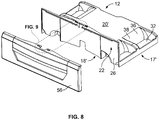
- Shroud 56 is shown in Fig. 8 .
- Shroud 56 is a wall member which can be positioned and releasably secured to, in this example, sidewall 26 of section 12 of cable pathway member 10.
- Shroud 56 provides an aesthetic appearance to cable pathway member 10 and, as will be discussed in more detail below, provides a confinement of other accessories positioned between sidewall 26 and shroud 56.
- shroud 56 is releasably secured to sidewall 26 by a snap fit structure.
- the snap fit structure in this example includes holes 58 positioned in substantially horizontal wall 60 positioned on and along the top of shroud 56 wherein a like wall (not shown) is positioned on the bottom of shroud 56.
- Horizontal wall 60 and the opposing wall (not shown) are spaced to provide a snug fit around receiving sidewall 26.
- horizontal wall 60 rides on top of wall member 62 positioned on sidewall 26 and engages ramp members 64.
- Resilient horizontal wall member 60 rides up ramp members 64 until holes 58, which are aligned with ramp members 64, engage ramp members 64 and provide a locking fit between shroud 56 and sidewall 26.
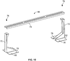
- a bracket assembly 66 can also be used with cable pathway member 10 as part of the cable pathway system to provide support to cable trough 68, which is positioned to extend over and spaced apart from top surface 20 of pathway member 10.
- Assembly 66 includes first and second supports 70 and 72 and cross bar 74, secured to first and second supports 70 and 72 with screws 76.
- Holes 78 are positioned in base plates 80 and 82 of first and second supports 70 and 72 respectively.
- Holes 78 in this example are spaced apart and positioned on their respective base plates to vertically align with holes 30 in each section 12 and 14 of cable pathway member 10. With holes 78 aligned with holes 30, the bolts or screws described above secure sections 12 and 14 to the top of enclosure 16 will likewise secure bracket assembly 66 to the top portion of enclosure 16.
- second support 72 is positioned on a rear or second side 24 on top of enclosure 16, wherein second support 72 extends above base 17.
- first support 70 is positioned on an opposing side of enclosure 16, front or first side 22, wherein support 70 extends above base 17.
- base plate 82 slides under an opening 84 of sidewall 26 and top portion 86 of second support 72 extends through notch 88 defined in wall member 62.
- first support 70 is similarly positioned with respect to base 17 on the opposite side of cable pathway member 10.
- shroud 56 is positioned to cover and confine first support member 70 and likewise a shroud 56 is provided on the opposing or second side 24 of enclosure 16 (not shown), which covers and confines second support member 72.
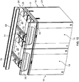
- Trough 68 is secured to cross bar 74, as seen in Fig. 12 , and can be used to carry cables that may need to be segregated from those cables positioned in cable pathway member 10.
- trough 68 can be releasably secured at any desired position along cross bar 74 utilizing clamp member 84.
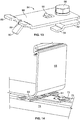
- clamp member 84 includes plate 86, which is adapted to overlie top surface 73 of cross bar 74, as seen in Fig. 14 .
- Spaced apart clamping feet 89 extend generally upwardly relative to plate 86 and are positionable to overlie rail 69 of trough 68, while at the same time, toe 90 extends down through slot or opening 75.
- Lower plate 92 positioned beneath plate 86 and beneath cross bar 74, has reverse configuration of feet 89 and toe 90 of plate 86.
- Lower plate 92 includes spaced apart feet 94 and toe 96, which extends upwardly through slot or opening 75.
- Bolt 98 passes through openings in both plate 86 and 92 and can be tightened or loosened to move plates 86 and 92 closer together or further apart.
- clamp member 84 can be employed such that feet 89 engage the top of rail 69 of trough 68. With feet 89 in position overlying rail 69, bolt 98 can be tightened, thereby clamping feet 89 down onto rail 69. Loosening bolt 98 will cause feet 89 to unclamp from rail 69.
- cable pathway member 10 is secured to the top of an electronic equipment enclosure 16 in two sections 12 and 14. Each section is positioned on the top of enclosure 16, aligned, and secured to enclosure 16. With sections 12 and 14 in proper position adjacent to and on top of enclosure 16, non-planar side surfaces 40 and 42 of the respective sections are in proper position, as discussed above, to resist relative movement between the two sections. Cable pathway member 10 is properly aligned on top of enclosure 16 such that sidewall 26 is aligned with front side 19 of enclosure 16 and sidewall 28 is aligned with rear or second side 21 of enclosure 16.
- bracket assembly 66 can be secured to the top of enclosure 16 by positioning first support 70 adjacent to first side 22 of base 17 and positioning second support 72 adjacent second side 24 of base 17.
- Cross bar 74 is secured to first and second supports 70 and 72, thereby positioning cross bar 74 spaced apart and over top surface 20 and base 17.
- trough 68 can be positioned and secured to cross bar 74 and supports 70 and 72 can be secured to top of enclosure 16.
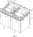
- a cable pathway member 10 can be secured to the top of each adjoining enclosure 16, as seen in Fig. 7 .
- a cable pathway system can be made from the aligned cable pathway members 10.
Description
- This invention relates to cable pathway systems and, more particularly, to cable pathway systems used in association with electronic equipment cabinets to form a pathway for cables which enter and exit the electronic equipment cabinets.
- Currently, typical cable pathway systems employ ladder racks or wire frame baskets. These racks and baskets are suspended from the ceiling by threaded rods embedded in the ceiling and may require additional time and/or labor to install. In addition, once these racks or baskets are installed, it is difficult to change or reconfigure the cable pathway systems without substantial labor. Furthermore, as the cooling requirements of data centers increase the height of the raised floor increases, thereby decreasing the clearance available between the top of the electronic equipment enclosures and the ceiling, making installation of these pathways even more difficult.
- Patent Application
US 2003/0051892 discloses a cable channel assembly comprising a segment to be attached to cable raceway for permitting cables to pass between the cable raceway and the cable channel segment.The segment provides a set of apertures having adjacent walls comprising curved surfaces. -
US Patent 6,586,680 proposes a fixture to be attached to a cable pathway having walls with curved surfaces. -
US Patent 5,969,292 discloses a cable pathway system configured to engage a top cover of an electronic equipment enclosure. - Therefore, there is a need for a cable pathway system that can be easily and quickly installed and reconfigured and that does not take up excessive space between the electronic equipment enclosures and the ceiling.
- According to the invention a cable pathway system is provided as defined in independent claim 1.
- Advantageous embodiments are defined in the dependent claims.
- Embodiments of the invention will now be described by way of example, with reference to the drawings. Certain examples of the present invention are illustrated by the accompanying figures. It should be understood that the figures are not necessarily to scale and that details that are not necessary for an understanding of the invention or that render other details difficult to perceive may be omitted. It should be understood, of course, that the invention is not necessarily limited to the particular examples illustrated herein.
-
Fig. 1 is a perspective exploded view of two sections of the cable pathway member of the cable pathway system; -
Fig. 2 is a top plan view of one section of the cable pathway member ofFig. 1 ; -
Fig. 3 is a top plan view of the of the two sections of the cable pathway member ofFig. 1 , assembled; -
Fig. 4 is a top perspective, exploded view of one section of the cable pathway member ofFig. 2 , positioned over the top of an electronic equipment cabinet (only the top portion of the electronic equipment cabinet is shown); -
Fig. 5 is a top perspective view of the cable pathway member ofFig. 3 , mounted to the top of an electronic equipment cabinet (only the top portion of the electronic equipment cabinet is shown); -
Fig. 6 is a perspective view of an insert; -
Fig. 7 is a perspective view of two cable pathway members positioned on the top of two adjacent electrical equipment cabinets (only the top portions of the electronic equipment cabinets are shown); -
Fig. 8 is an exploded view of a shroud and one section of a cable pathway member; -
Fig. 9 is a enlarged view of the shroud and a sidewall of the cable pathway member ofFig. 8 ; -
Fig. 10 is a bracket assembly; -
Fig. 11 is a partial cut away view of a section of the cable pathway member positioned on top of an electronic equipment cabinet and an exploded view of the bracket assembly seen inFig. 10 in relation to the section of the cable pathway member; -
Fig. 12 is a top perspective view of two cable pathway systems positioned on top of two adjacent electronic equipment cabinets; -
Fig. 13 is a perspective view of a mounting bracket; and -
Fig. 14 is a partial cut away view of a cable trough secured to the bracket assembly ofFig. 12 utilizing the mounting bracket ofFig. 13 . - Referring to
Fig. 1 , one example of the cable pathway system, utilized to carry various electronic cables for power and communication, includes acable pathway member 10. In this example,cable pathway member 10 is shown in twosections cable pathway member 10. Alternative examples could includepathway member 10 constructed of a single piece or even constructed of a greater number of sections than shown inFig. 1 . - With
sections Figs. 3 and5 ,cable pathway member 10 is in its proper configuration to carry various electronic cables and is sized to be positioned on a top of anelectronic equipment enclosure 16. In the current example,enclosure 16 is shown as a cabinet. However,enclosure 16 may be any number of structures such as a four post rack, a cable manager, a network cabinet, a server cabinet or any other structure designed to carry electronic equipment serviced by electronic power and/or communication cables.Cable pathway member 10 provides a pathway for positioning electronic cables along the top of anelectronic equipment enclosure 16. Withcable pathway 10 positioned on top ofenclosure 16, installation and maintenance of the cables that service the electronic equipment disposed within theelectronic equipment enclosure 16 is made easier and more convenient. - In the example shown in
Fig. 1 , each ofsections Sections bottom 18' and a generally planar top surface 20'. Withsections Figs. 3 and5 ,cable pathway member 10 is formed and a completedbase 17,bottom 18, and generally planartop surface 20 are formed. Withsections first side 22 and asecond side 24 are provided on opposing sides ofpathway member 10.First side 22 comprises afirst sidewall 26 andsecond side 24 comprisessecond sidewall 28. First andsecond sidewalls planar surface 20 and extend substantially along a length of their respective first andsecond sides second sidewalls pathway member 10. Moreover,cable pathway member 10 is sized such thatfirst sidewall 26 generally aligns with afront side 19 ofelectronic equipment enclosure 16 andsecond sidewall 28 generally aligns with aback side 21 ofelectronic equipment enclosure 16. -
Cable pathway member 10 is configured to be secured to the top ofcabinet 16 by providing, in this example, one ormore holes 30 which pass through the base of eachsection cable pathway member 10 on the top of electronic
equipment enclosure 16, one or more ofholes 30 are positioned to each align with a corresponding hole (not shown) inelectronic equipment enclosure 16. A bolt or screw can be passed through ahole 30 and its corresponding aligned hole inenclosure 16 thereby allowingcable pathway member 10 to be secured via a nut or other fastener toelectronic equipment enclosure 16. -
Cable pathway member 10 is generally constructed of a molded plastic or other non-metallic material. In the example shown herein,pathway member 10 is constructed of a molded plastic. Sincepathway member 10 may be required to carry a substantial amount of cables and thereby a substantial amount of weight, it is desired thatbase 17 be constructed of a solid construction and/or be provided with strengthening ribs to reinforce the underside ofbase 17. To support the weight of the cables positioned withincable pathway member 10, it is also desirable to position portions ofbase 17 to overlie portions ofelectronic equipment enclosure 16 such that the portion ofbase 17 which carries a larger load receives underlying support from a support structure withinenclosure 16. Providing such support will preventpathway member 10 from sagging from larger cable loads. -
Base 17 ofcable pathway member 10 defines at least oneaperture 32 which passes fromtop surface 20 throughbottom 18 ofbase 17. Positioned adjacent toaperture 32 iswall 36, which comprises acurved surface 38 that extends fromtop surface 20 tobottom 18 ofbase 17.Wall 36 supports cables which overlietop surface 20 and extend into and out ofelectronic equipment enclosure 16 throughaperture 32. The radius of curvature ofwall 36 is generally 76.2 mm (3 inches), but can be configured with any appropriate radius of curvature that will provide a smooth transition of the change of direction of the cable. The cable is positioned to extend generally horizontal incable pathway member 10 and then changes to extend generally vertical with the cable entering or exiting fromenclosure 16. Curvedsurface 38 provides a smooth transition of the cable as it changes direction and preserves the integrity of the cable and reliability of transmission. - As can be seen in
Figs. 3-5 , afirst set 31 ofapertures 32 are positioned adjacent to and along athird side 25 ofcable pathway member 10 and asecond set 35 ofapertures 32 are positioned adjacent to and along an opposingfourth side 27 ofcable pathway member 10. As described above, each of theseapertures 32 comprises awall 36 with acurved surface 38 positioned adjacent toapertures 32. Again, in this example, the radius of curvature ofwall 36 is 76.2 mm (3 inches) but can be configured with a radius that will provide a smooth transition for the cable as it changes direction. In this example, the first andsecond sets apertures 32 each form a row wherein, withcable pathway member 10 secured toenclosure 16, eachaperture 32 is positioned to vertically align with anopening 37 positioned withintop cover 39 ofenclosure 16. With eachaperture 32 vertically aligned with anopening 37, cables are easily positioned to extend into and out ofenclosure 16 throughtop cover 39 and engagecurved surface 38 to provide a smooth transition of the cable extending from inside ofenclosure 16 to alongtop surface 20 ofcable pathway member 10. - As described above for this example,
sections cable pathway member 10. To facilitate alignment ofsections section Fig. 1 ,non-planar side surface 40 ofsection 12 is positioned on an opposite side ofsection 12 fromsidewall 26 and similarly,non-planar side surface 42 ofsection 14 is positioned on an opposite side ofsection 14 fromsidewall 28. Non-planar side surfaces 40 and 42 complement one another and form mating surfaces such that withsections base 17. For example, with aprotrusion 44 positioned inside surface 40 fitting into arecess 46 inside surface 42, relative movement betweensections - Referring to
Fig. 6 , aninsert 48 is shown.Insert 48 is positionable intoaperture 32, as seen inFig. 7 , thereby blockingsuch aperture 32 and preventing cable from entering or exiting thataperture 32. As can be seen inFig. 7 , in thisexample insert 48 has a size and shape such that one insert will prevent access to half ofaperture 32, allowing more flexibility in the installation of the cable pathway system. However, instead of, or in addition toinserts 48, there could also be inserts that fill all ofaperture 32 or that block any other fraction ofaperture 32 desired.Insert 48 also provides a support surface for cables positioned incable pathway member 10 and provides atop surface 50 which is generally planar and aligns generally with topplanar surface 20 ofbase 17.Insert 48 also hascurved surface 52 and, as described earlier forcurved surface 38 positioned incable pathway member 10,curved surface 52 comprises a radius of curvature of 76.2 mm (3 inches). As discussed above forcurved surface 38,curved surface 52 can be configured with any radius of curvature that will provide a smooth transition of direction for cable positioned generally horizontal incable member pathway 10 to a generally vertical position of cable entering or exiting from anadjacent enclosure 16. Such curved transition preserves the integrity of the cable and reliability of transmission. A snaprelease locking mechanism 54 is provided to removeablysecure insert 48 to a compatible structure inbase 17.Insert 48 can be easily locked into and unlocked from a desiredaperture 32 and thereby cable routing pathways can be configured as needed. -
Shroud 56 is shown inFig. 8 .Shroud 56 is a wall member which can be positioned and releasably secured to, in this example,sidewall 26 ofsection 12 ofcable pathway member 10.Shroud 56 provides an aesthetic appearance tocable pathway member 10 and, as will be discussed in more detail below, provides a confinement of other accessories positioned betweensidewall 26 andshroud 56. - As seen in
Fig. 9 ,shroud 56 is releasably secured to sidewall 26 by a snap fit structure. The snap fit structure in this example includesholes 58 positioned in substantiallyhorizontal wall 60 positioned on and along the top ofshroud 56 wherein a like wall (not shown) is positioned on the bottom ofshroud 56.Horizontal wall 60 and the opposing wall (not shown) are spaced to provide a snug fit around receivingsidewall 26. Thus, withshroud 56 pushed ontosidewall 26,horizontal wall 60 rides on top ofwall member 62 positioned onsidewall 26 and engagesramp members 64. Resilienthorizontal wall member 60 rides upramp members 64 untilholes 58, which are aligned withramp members 64, engageramp members 64 and provide a locking fit betweenshroud 56 andsidewall 26. - As shown in
Figs. 10-12 , abracket assembly 66 can also be used withcable pathway member 10 as part of the cable pathway system to provide support tocable trough 68, which is positioned to extend over and spaced apart fromtop surface 20 ofpathway member 10.Assembly 66 includes first andsecond supports cross bar 74, secured to first andsecond supports screws 76.Holes 78 are positioned inbase plates second supports Holes 78, in this example are spaced apart and positioned on their respective base plates to vertically align withholes 30 in eachsection cable pathway member 10. Withholes 78 aligned withholes 30, the bolts or screws described abovesecure sections enclosure 16 will likewise securebracket assembly 66 to the top portion ofenclosure 16. - As seen in
Fig. 11 ,second support 72 is positioned on a rear orsecond side 24 on top ofenclosure 16, whereinsecond support 72 extends abovebase 17. Similarly,first support 70 is positioned on an opposing side ofenclosure 16, front orfirst side 22, whereinsupport 70 extends abovebase 17. As seen with respect tobase plate 82,base plate 82 slides under anopening 84 ofsidewall 26 andtop portion 86 ofsecond support 72 extends throughnotch 88 defined inwall member 62. Again,first support 70 is similarly positioned with respect tobase 17 on the opposite side ofcable pathway member 10. As seen inFig. 12 ,shroud 56 is positioned to cover and confinefirst support member 70 and likewise ashroud 56 is provided on the opposing orsecond side 24 of enclosure 16 (not shown), which covers and confinessecond support member 72. -
Trough 68 is secured to crossbar 74, as seen inFig. 12 , and can be used to carry cables that may need to be segregated from those cables positioned incable pathway member 10. As may be appreciated in referring toFigs. 13 and 14 ,trough 68 can be releasably secured at any desired position alongcross bar 74 utilizingclamp member 84. As seen inFig. 13 ,clamp member 84 includesplate 86, which is adapted to overlietop surface 73 ofcross bar 74, as seen inFig. 14 . Spaced apart clampingfeet 89 extend generally upwardly relative to plate 86 and are positionable to overlierail 69 oftrough 68, while at the same time,toe 90 extends down through slot oropening 75.Lower plate 92, positioned beneathplate 86 and beneathcross bar 74, has reverse configuration offeet 89 andtoe 90 ofplate 86.Lower plate 92 includes spaced apartfeet 94 andtoe 96, which extends upwardly through slot oropening 75.Bolt 98 passes through openings in bothplate plates trough 68 positioned at a desired location oncross bar 74,clamp member 84 can be employed such thatfeet 89 engage the top ofrail 69 oftrough 68. Withfeet 89 inposition overlying rail 69,bolt 98 can be tightened, thereby clampingfeet 89 down ontorail 69. Looseningbolt 98 will causefeet 89 to unclamp fromrail 69. - In assembling the exemplary cable pathway system,
cable pathway member 10 is secured to the top of anelectronic equipment enclosure 16 in twosections enclosure 16, aligned, and secured toenclosure 16. Withsections enclosure 16, non-planar side surfaces 40 and 42 of the respective sections are in proper position, as discussed above, to resist relative movement between the two sections.Cable pathway member 10 is properly aligned on top ofenclosure 16 such thatsidewall 26 is aligned withfront side 19 ofenclosure 16 andsidewall 28 is aligned with rear orsecond side 21 ofenclosure 16. - As seen in
Figs. 3 and5 , withbase 17 properly positioned on top ofenclosure 16,apertures 32 formed inbase 17 align withopenings 37 formed in a top cover 39 (seeFig. 4 ) ofenclosure 16. Securingbase 17 toenclosure 16 is accomplished by bolts inserted throughholes 30, wherein, as described above, the bolts engage corresponding aligned holes inenclosure 16, thereby boltingcable pathway member 10 toenclosure 16. - Additionally,
bracket assembly 66 can be secured to the top ofenclosure 16 by positioningfirst support 70 adjacent tofirst side 22 ofbase 17 and positioningsecond support 72 adjacentsecond side 24 ofbase 17.Cross bar 74 is secured to first andsecond supports cross bar 74 spaced apart and overtop surface 20 andbase 17. As described above,trough 68 can be positioned and secured to crossbar 74 and supports 70 and 72 can be secured to top ofenclosure 16. - As can be appreciated from the above description, in the installation of electronic equipment, a
cable pathway member 10 can be secured to the top of each adjoiningenclosure 16, as seen inFig. 7 . Thus, with a number ofenclosures 16 so configured, a cable pathway system can be made from the alignedcable pathway members 10.
Claims (12)
- A cable pathway system, comprising:a base (17) comprising a bottom (18), a generally planar top surface (20), a first side (22), a second side (24), a third side (25) and a fourth side (27), wherein the bottom (18) of the base (17) is configured to engage a top cover (39) of an electronic equipment enclosure (16);the base (17) further comprising a first aperture (32) or set of apertures (31) formed therein adjacent to the third side (25) of the base (17) and a second aperture (32) or set of apertures (35) formed therein adjacent to the fourth side (27) of the base (17), and a wall (36) positioned adjacent to each aperture (32), wherein each wall (36) comprises a curved surface (38) that extends from the top surface (20) to the bottom (18);a first sidewall (26) extending from the top surface (20) along the first side (22), the first sidewall (26) extending generally perpendicular to the top surface (20) and substantially along the length of the first side (22); anda second sidewall (28) extending from the top surface (20) along the second side (24), the second sidewall (28) extending generally perpendicular to the top surface (20) and substantially along the length of the second side (24),wherein the first and second sidewalls (26, 28) define a cable pathway (10) on the top surface (20) of the base (17), between the first aperture (32) or set of apertures (31) and the second aperture (32) or set of apertures (35).
- The cable pathway system of claim 1, wherein the curved surface (38) comprises a radius of curvature of 76.2 mm (3 inches).
- The cable pathway system of claim 1 or claim 2, wherein the base (17) comprises:a first set (31) of apertures (32) formed therein, which are positioned adjacent a third side (25) of the base (17), and a first set of walls (36) corresponding to the first set (31) of apertures (32) and positioned adjacent to the first set (31) of apertures (32), wherein each wall (36) comprises a curved surface (38) that extends from the top surface (20) to the bottom (18); anda second set (35) of apertures (32) formed therein, which are positioned adjacent a fourth side (27) of the base (17), and a second set of walls (36) corresponding to the second set (35) of apertures (32) and positioned adjacent to the second set (35) of apertures (32), wherein each wall (36) comprises a curved surface (38) that extends from the top surface (20) to the bottom (18).
- The cable pathway system of claim 3, wherein each of the curved surfaces (38) comprises a radius of curvature of 76.2 mm (3 inches).
- The cable pathway system of any preceding claim, wherein the base (17) comprises a first section (12) and a second section (14).
- The cable pathway system of claim 5, wherein the first section (12) and the second section (14) comprise matching non-planar side surfaces (40, 42) configured to mate together to form the base (17).
- The cable pathway system of claim 6, wherein the first sidewall (26) is disposed along one side of the first section (12), opposite the non-planar side surface (40), and the second sidewall (28) is disposed along one side of the second section (14), opposite the non-planar side surface (42).
- The cable pathway system of any preceding claim, further comprising a shroud (56) removeably secured to the first sidewall (26).
- The cable pathway system of any preceding claim, further comprising an insert (48) positionable within the aperture (32) to prevent access to at least a portion of the aperture (32), the insert (48) comprising a top surface (50) comprising a generally planar section that generally aligns with the top surface (20) of the base (17) when the insert (48) is positioned within the aperture (32).
- The cable pathway system of claim 9, wherein the top surface (50) of the insert (48) further comprises a curved section (52) adjacent the planar section.
- The cable pathway system of claim 10, wherein the curved section (52) comprises a radius of curvature of 76.2 mm (3 inches).
- The cable pathway system of any preceding claim, further comprising:a first support (70) positioned adjacent the first side of the base (17) and extending above the base (17);a second support (72) positioned adjacent the second side of the base (17) and extending above the base (17);a cross bar (74) secured between the first and second supports (70, 72) and extending over the base (17); anda cable trough (68) secured to the cross bar (74).
Applications Claiming Priority (1)
| Application Number | Priority Date | Filing Date | Title |
|---|---|---|---|
| US11/924,800 US8047474B2 (en) | 2007-10-26 | 2007-10-26 | Cable pathway system |
Publications (3)
| Publication Number | Publication Date |
|---|---|
| EP2053715A2 EP2053715A2 (en) | 2009-04-29 |
| EP2053715A3 EP2053715A3 (en) | 2016-10-05 |
| EP2053715B1 true EP2053715B1 (en) | 2020-01-08 |
Family
ID=40260562
Family Applications (1)
| Application Number | Title | Priority Date | Filing Date |
|---|---|---|---|
| EP08253388.6A Active EP2053715B1 (en) | 2007-10-26 | 2008-10-20 | Cable pathway system |
Country Status (2)
| Country | Link |
|---|---|
| US (3) | US20090107696A1 (en) |
| EP (1) | EP2053715B1 (en) |
Families Citing this family (11)
| Publication number | Priority date | Publication date | Assignee | Title |
|---|---|---|---|---|
| DE102008016631B4 (en) | 2008-04-01 | 2014-12-11 | BSH Bosch und Siemens Hausgeräte GmbH | Cable holder, household appliance and method for laying cables in a household appliance |
| US8193448B2 (en) * | 2009-10-29 | 2012-06-05 | American Power Conversion Corporation | Systems and methods of managing cables |
| WO2013130919A2 (en) * | 2012-02-29 | 2013-09-06 | Inertech Ip Llc | Air flow distribution system for data center server racks |
| DE202013001434U1 (en) * | 2013-02-15 | 2013-03-08 | Ccs Technology, Inc. | Device for horizontal guidance of fiber optic cables and for horizontal storage of excess lengths of the optical fiber cable |
| CA2904203C (en) * | 2013-03-07 | 2021-04-27 | Cooper Technologies Company | Clamp device for cable tray assembly |
| USD777115S1 (en) | 2015-09-25 | 2017-01-24 | Sumitomo Wiring Systems, Ltd. | Wire harness protector |
| USD786198S1 (en) | 2015-09-25 | 2017-05-09 | Sumitomo Wiring Systems, Ltd. | Wire harness protector |
| JP1548601S (en) * | 2015-09-25 | 2016-05-09 | ||
| JP1548602S (en) | 2015-09-25 | 2016-05-09 | ||
| USD761209S1 (en) * | 2015-09-25 | 2016-07-12 | Sumitomo Wiring Systems, Ltd. | Wire harness protector |
| US10334748B1 (en) | 2018-02-23 | 2019-06-25 | International Business Machines Corporation | Top-mount cable management structure(s) for an electronics rack |
Family Cites Families (47)
| Publication number | Priority date | Publication date | Assignee | Title |
|---|---|---|---|---|
| US952227A (en) * | 1910-03-15 | Proximity Mfg Company | Warp-beam for looms. | |
| US3968322A (en) | 1971-07-26 | 1976-07-06 | Taylor Industries, Inc. | Wiring duct |
| JPS5227202A (en) | 1975-08-25 | 1977-03-01 | Fujitsu Ltd | Communication equipment rack |
| US4141524A (en) * | 1977-02-28 | 1979-02-27 | Corvese Jr Louis | Tube holder for immobile patients |
| US4320261A (en) * | 1980-10-03 | 1982-03-16 | Bell Telephone Laboratories, Incorporated | Cable routing methods and apparatus |
| US4363459A (en) * | 1980-12-05 | 1982-12-14 | Joanna Western Mills Company | Adjustable wall mounted bracket |
| SE458079B (en) * | 1987-06-30 | 1989-02-20 | Ericsson Telefon Ab L M | DEVICE FOR LEADING TELEPHONE CABLES FROM A FIXED HORIZONTAL CABLE ROAD IN A TELEPHONE STATION TO PHONE EQUIPMENT IN A SHELF STAND IN THE CALLED TELEPHONE STATION |
| US4907766A (en) * | 1989-01-24 | 1990-03-13 | B-Line Systems, Inc. | Pipe positioning and support system |
| US4938432A (en) * | 1989-04-12 | 1990-07-03 | Cooper Industries, Inc. | Cable spool with integral end storage flange |
| US5067678A (en) * | 1989-07-31 | 1991-11-26 | Adc Telecommunications, Inc. | Optic cable management system |
| US4956948A (en) * | 1989-10-19 | 1990-09-18 | Richard Hart | Clog resistant gutter-downspout connection unit |
| US5142606A (en) * | 1990-01-22 | 1992-08-25 | Porta Systems Corp. | Optical fiber cable distribution frame and support |
| US5044589A (en) * | 1990-06-25 | 1991-09-03 | Milne Fred W | Vertical wall covering bracket assembly |
| US5372341A (en) * | 1993-10-06 | 1994-12-13 | B-Line Systems, Inc. | Cable tray hold-down device |
| US5580014A (en) * | 1993-12-22 | 1996-12-03 | B-Line Systems, Inc. | Ladder-type cable tray |
| US5503354A (en) * | 1994-01-04 | 1996-04-02 | Telect, Inc. | Telecommunication overhead cable distribution universal support bracket |
| US6002089A (en) | 1997-09-26 | 1999-12-14 | The Wiremold Company | Non-linear raceway section having radial insert |
| US5969292A (en) | 1997-11-07 | 1999-10-19 | Ericsson, Inc. | Overhead cabling system for telecommunication switching center |
| US5923753A (en) | 1997-11-17 | 1999-07-13 | Adc Telecommunications, Inc. | Optic cable exit trough with bypass |
| US5937131A (en) * | 1997-11-17 | 1999-08-10 | Adc Telecommunications, Inc. | Optical cable exit trough |
| US6107576A (en) * | 1998-02-26 | 2000-08-22 | Newton Instruments Company, Inc. | Hinged top lid for cable channel |
| US6129316A (en) * | 1998-07-23 | 2000-10-10 | The Siemon Company | Telecommunications rack cable support bracket |
| US6437243B1 (en) * | 1999-03-03 | 2002-08-20 | Panduit Corp. | Wireway system having a pivotable cover |
| US6263144B1 (en) | 1999-09-07 | 2001-07-17 | Lucent Technologies Inc. | Fiber-optic cable routing and storage device |
| US6271476B1 (en) * | 1999-12-13 | 2001-08-07 | The Siemon Company | Bend radius guide |
| US6388193B2 (en) * | 2000-01-12 | 2002-05-14 | The Siemon Company | Stackable bend radius guide |
| US6310294B1 (en) | 2000-04-03 | 2001-10-30 | At&T Corp. | Vertical separation rack for cable management |
| US6586680B1 (en) | 2000-06-02 | 2003-07-01 | Panduit Corp. | Modular bend radius control fixture |
| US6541704B1 (en) * | 2000-06-27 | 2003-04-01 | Bellsouth Intellectual Property Corporation | Line management housing and line routing device therein |
| US6365830B1 (en) * | 2000-06-30 | 2002-04-02 | Ericsson Inc. | Overhead cabling system for a telecommunications switching center |
| US6541705B1 (en) * | 2000-07-28 | 2003-04-01 | Panduit Corp. | Cable management rack |
| US7155104B2 (en) * | 2000-10-06 | 2006-12-26 | Adc Telecommunications, Inc. | Cable exit trough with insert |
| US6625373B1 (en) * | 2000-10-06 | 2003-09-23 | Adc Telecommunications, Inc. | Cable exit trough with insert |
| DE20021918U1 (en) * | 2000-12-23 | 2002-04-25 | Tehalit Gmbh | Device for fastening conduit ducts to walls |
| US6546179B2 (en) * | 2001-01-25 | 2003-04-08 | Hector D. Petri | Guide for routing cables through panel openings |
| US6992247B2 (en) * | 2002-01-02 | 2006-01-31 | American Power Conversion Corporation | Toolless mounting system and method for an adjustable scalable rack power system |
| US6967283B2 (en) * | 2001-03-20 | 2005-11-22 | American Power Conversion Corporation | Adjustable scalable rack power system and method |
| US6585195B2 (en) * | 2001-04-25 | 2003-07-01 | Adc Telecommunications, Inc. | Cable management system including variable segments |
| US6631874B2 (en) * | 2001-06-01 | 2003-10-14 | Telect, Inc. | Adjustable fiber optic cable trough bracket |
| US6412733B1 (en) | 2001-06-04 | 2002-07-02 | Panduit Corp. | Support brackets for cable raceway |
| US6603073B2 (en) | 2001-09-12 | 2003-08-05 | Adc Telecommunications, Inc. | Snap together cable trough system |
| US20030051892A1 (en) * | 2001-09-14 | 2003-03-20 | Michael Mattei | Cable channel assembly |
| ITTO20020025U1 (en) * | 2002-02-06 | 2003-08-06 | Legrand Spa | DEVICE FOR FASTENING NETWORK CABLE TRAYS ON A SUPPORT SHELF. |
| US6756539B1 (en) * | 2003-03-20 | 2004-06-29 | Panduit Corp. | Adjustable mid-panel spillover fitting |
| ITRM20050239A1 (en) * | 2005-05-17 | 2006-11-18 | Bticino Spa | COLUMN FOR THE HOUSING OF ELECTRIC APPLIANCES, PARTICULARLY FOR APPLIANCES OF DOMESTIC AUTOMATION SYSTEMS. |
| ES2250012B1 (en) * | 2005-09-19 | 2006-12-16 | Unex Aparellaje Electrico, S.L. | CHANNEL FOR ELECTRICAL CONDUCTORS. |
| US7584929B2 (en) * | 2007-02-21 | 2009-09-08 | Adc Telecommunications, Inc. | Coupler for cable trough |
-
2007
- 2007-10-26 US US11/924,922 patent/US20090107696A1/en not_active Abandoned
- 2007-10-26 US US11/924,897 patent/US7763800B2/en not_active Expired - Fee Related
- 2007-10-26 US US11/924,800 patent/US8047474B2/en not_active Expired - Fee Related
-
2008
- 2008-10-20 EP EP08253388.6A patent/EP2053715B1/en active Active
Non-Patent Citations (1)
| Title |
|---|
| None * |
Also Published As
| Publication number | Publication date |
|---|---|
| EP2053715A2 (en) | 2009-04-29 |
| US8047474B2 (en) | 2011-11-01 |
| EP2053715A3 (en) | 2016-10-05 |
| US20090107696A1 (en) | 2009-04-30 |
| US20090108145A1 (en) | 2009-04-30 |
| US20090107718A1 (en) | 2009-04-30 |
| US7763800B2 (en) | 2010-07-27 |
Similar Documents
| Publication | Publication Date | Title |
|---|---|---|
| EP2053715B1 (en) | Cable pathway system | |
| EP2494858B1 (en) | Systems and methods of managing cables | |
| EP2528349B1 (en) | Bracket to be used in a vertical cable manager | |
| EP1336360B2 (en) | Support structure with an adjustable bracket for a storage system | |
| EP3014325B1 (en) | Cable management structure for an optical fiber distribution rack | |
| US20100110621A1 (en) | Rack with vertical mounting providing room for rack pdu | |
| US20150163953A1 (en) | Uniform equipment mounting system | |
| US6429376B1 (en) | Add-on trough for cable management rack | |
| CA2430136A1 (en) | Earthquake resistant equipment rack | |
| US8833711B2 (en) | Two post rack with floor mounting brackets | |
| US6111195A (en) | Communications cabinet and mounting system | |
| PL193564B1 (en) | Apparatus support, in particular for electrical apparatus, and box comprising such an apparatus support | |
| US20040144737A1 (en) | Mounting tray for idc junction modules | |
| US20100101855A1 (en) | Cable raceway with box | |
| US11698502B2 (en) | Bracket arrangement for cable trough system | |
| CN110915080A (en) | Arrangement of a switchgear cabinet base and a switchgear cabinet rack mounted thereon, and corresponding switchgear cabinet column | |
| US20040145837A1 (en) | Basepan assembly | |
| US20230063648A1 (en) | Modular electrical-cabinet mounting apparatus | |
| WO2001006293A1 (en) | Versatile optical fibre distribution rack | |
| WO1998047339A1 (en) | Joint and a stackable module for electronic equipment |
Legal Events
| Date | Code | Title | Description |
|---|---|---|---|
| PUAI | Public reference made under article 153(3) epc to a published international application that has entered the european phase |
Free format text: ORIGINAL CODE: 0009012 |
|
| AK | Designated contracting states |
Kind code of ref document: A2 Designated state(s): AT BE BG CH CY CZ DE DK EE ES FI FR GB GR HR HU IE IS IT LI LT LU LV MC MT NL NO PL PT RO SE SI SK TR |
|
| AX | Request for extension of the european patent |
Extension state: AL BA MK RS |
|
| PUAL | Search report despatched |
Free format text: ORIGINAL CODE: 0009013 |
|
| AK | Designated contracting states |
Kind code of ref document: A3 Designated state(s): AT BE BG CH CY CZ DE DK EE ES FI FR GB GR HR HU IE IS IT LI LT LU LV MC MT NL NO PL PT RO SE SI SK TR |
|
| AX | Request for extension of the european patent |
Extension state: AL BA MK RS |
|
| RIC1 | Information provided on ipc code assigned before grant |
Ipc: H02G 3/30 20060101ALI20160831BHEP Ipc: H02G 3/04 20060101AFI20160831BHEP |
|
| STAA | Information on the status of an ep patent application or granted ep patent |
Free format text: STATUS: REQUEST FOR EXAMINATION WAS MADE |
|
| 17P | Request for examination filed |
Effective date: 20170405 |
|
| RBV | Designated contracting states (corrected) |
Designated state(s): AT BE BG CH CY CZ DE DK EE ES FI FR GB GR HR HU IE IS IT LI LT LU LV MC MT NL NO PL PT RO SE SI SK TR |
|
| RBV | Designated contracting states (corrected) |
Designated state(s): AT BE BG CH CY CZ DE DK EE ES FI FR GB GR HR HU IE IS IT LI LT LU LV MC MT NL NO PL PT RO SE SI SK TR |
|
| AKX | Designation fees paid |
Designated state(s): AT BE BG CH CY CZ DE DK EE ES FI FR GB GR HR HU IE IS IT LI LT LU LV MC MT NL NO PL PT RO SE SI SK TR |
|
| AXX | Extension fees paid |
Extension state: AL Extension state: MK Extension state: RS Extension state: BA |
|
| STAA | Information on the status of an ep patent application or granted ep patent |
Free format text: STATUS: EXAMINATION IS IN PROGRESS |
|
| 17Q | First examination report despatched |
Effective date: 20181205 |
|
| GRAP | Despatch of communication of intention to grant a patent |
Free format text: ORIGINAL CODE: EPIDOSNIGR1 |
|
| STAA | Information on the status of an ep patent application or granted ep patent |
Free format text: STATUS: GRANT OF PATENT IS INTENDED |
|
| INTG | Intention to grant announced |
Effective date: 20190826 |
|
| GRAS | Grant fee paid |
Free format text: ORIGINAL CODE: EPIDOSNIGR3 |
|
| GRAA | (expected) grant |
Free format text: ORIGINAL CODE: 0009210 |
|
| STAA | Information on the status of an ep patent application or granted ep patent |
Free format text: STATUS: THE PATENT HAS BEEN GRANTED |
|
| AK | Designated contracting states |
Kind code of ref document: B1 Designated state(s): AT BE BG CH CY CZ DE DK EE ES FI FR GB GR HR HU IE IS IT LI LT LU LV MC MT NL NO PL PT RO SE SI SK TR |
|
| REG | Reference to a national code |
Ref country code: GB Ref legal event code: FG4D |
|
| REG | Reference to a national code |
Ref country code: CH Ref legal event code: EP |
|
| REG | Reference to a national code |
Ref country code: DE Ref legal event code: R096 Ref document number: 602008061961 Country of ref document: DE |
|
| REG | Reference to a national code |
Ref country code: IE Ref legal event code: FG4D |
|
| REG | Reference to a national code |
Ref country code: AT Ref legal event code: REF Ref document number: 1223855 Country of ref document: AT Kind code of ref document: T Effective date: 20200215 |
|
| REG | Reference to a national code |
Ref country code: NL Ref legal event code: MP Effective date: 20200108 |
|
| REG | Reference to a national code |
Ref country code: LT Ref legal event code: MG4D |
|
| PG25 | Lapsed in a contracting state [announced via postgrant information from national office to epo] |
Ref country code: FI Free format text: LAPSE BECAUSE OF FAILURE TO SUBMIT A TRANSLATION OF THE DESCRIPTION OR TO PAY THE FEE WITHIN THE PRESCRIBED TIME-LIMIT Effective date: 20200108 Ref country code: NO Free format text: LAPSE BECAUSE OF FAILURE TO SUBMIT A TRANSLATION OF THE DESCRIPTION OR TO PAY THE FEE WITHIN THE PRESCRIBED TIME-LIMIT Effective date: 20200408 Ref country code: PT Free format text: LAPSE BECAUSE OF FAILURE TO SUBMIT A TRANSLATION OF THE DESCRIPTION OR TO PAY THE FEE WITHIN THE PRESCRIBED TIME-LIMIT Effective date: 20200531 Ref country code: NL Free format text: LAPSE BECAUSE OF FAILURE TO SUBMIT A TRANSLATION OF THE DESCRIPTION OR TO PAY THE FEE WITHIN THE PRESCRIBED TIME-LIMIT Effective date: 20200108 Ref country code: LT Free format text: LAPSE BECAUSE OF FAILURE TO SUBMIT A TRANSLATION OF THE DESCRIPTION OR TO PAY THE FEE WITHIN THE PRESCRIBED TIME-LIMIT Effective date: 20200108 |
|
| PG25 | Lapsed in a contracting state [announced via postgrant information from national office to epo] |
Ref country code: BG Free format text: LAPSE BECAUSE OF FAILURE TO SUBMIT A TRANSLATION OF THE DESCRIPTION OR TO PAY THE FEE WITHIN THE PRESCRIBED TIME-LIMIT Effective date: 20200408 Ref country code: GR Free format text: LAPSE BECAUSE OF FAILURE TO SUBMIT A TRANSLATION OF THE DESCRIPTION OR TO PAY THE FEE WITHIN THE PRESCRIBED TIME-LIMIT Effective date: 20200409 Ref country code: IS Free format text: LAPSE BECAUSE OF FAILURE TO SUBMIT A TRANSLATION OF THE DESCRIPTION OR TO PAY THE FEE WITHIN THE PRESCRIBED TIME-LIMIT Effective date: 20200508 Ref country code: SE Free format text: LAPSE BECAUSE OF FAILURE TO SUBMIT A TRANSLATION OF THE DESCRIPTION OR TO PAY THE FEE WITHIN THE PRESCRIBED TIME-LIMIT Effective date: 20200108 Ref country code: LV Free format text: LAPSE BECAUSE OF FAILURE TO SUBMIT A TRANSLATION OF THE DESCRIPTION OR TO PAY THE FEE WITHIN THE PRESCRIBED TIME-LIMIT Effective date: 20200108 Ref country code: HR Free format text: LAPSE BECAUSE OF FAILURE TO SUBMIT A TRANSLATION OF THE DESCRIPTION OR TO PAY THE FEE WITHIN THE PRESCRIBED TIME-LIMIT Effective date: 20200108 |
|
| REG | Reference to a national code |
Ref country code: DE Ref legal event code: R097 Ref document number: 602008061961 Country of ref document: DE |
|
| PG25 | Lapsed in a contracting state [announced via postgrant information from national office to epo] |
Ref country code: ES Free format text: LAPSE BECAUSE OF FAILURE TO SUBMIT A TRANSLATION OF THE DESCRIPTION OR TO PAY THE FEE WITHIN THE PRESCRIBED TIME-LIMIT Effective date: 20200108 Ref country code: DK Free format text: LAPSE BECAUSE OF FAILURE TO SUBMIT A TRANSLATION OF THE DESCRIPTION OR TO PAY THE FEE WITHIN THE PRESCRIBED TIME-LIMIT Effective date: 20200108 Ref country code: SK Free format text: LAPSE BECAUSE OF FAILURE TO SUBMIT A TRANSLATION OF THE DESCRIPTION OR TO PAY THE FEE WITHIN THE PRESCRIBED TIME-LIMIT Effective date: 20200108 Ref country code: EE Free format text: LAPSE BECAUSE OF FAILURE TO SUBMIT A TRANSLATION OF THE DESCRIPTION OR TO PAY THE FEE WITHIN THE PRESCRIBED TIME-LIMIT Effective date: 20200108 Ref country code: CZ Free format text: LAPSE BECAUSE OF FAILURE TO SUBMIT A TRANSLATION OF THE DESCRIPTION OR TO PAY THE FEE WITHIN THE PRESCRIBED TIME-LIMIT Effective date: 20200108 Ref country code: RO Free format text: LAPSE BECAUSE OF FAILURE TO SUBMIT A TRANSLATION OF THE DESCRIPTION OR TO PAY THE FEE WITHIN THE PRESCRIBED TIME-LIMIT Effective date: 20200108 |
|
| PLBE | No opposition filed within time limit |
Free format text: ORIGINAL CODE: 0009261 |
|
| STAA | Information on the status of an ep patent application or granted ep patent |
Free format text: STATUS: NO OPPOSITION FILED WITHIN TIME LIMIT |
|
| REG | Reference to a national code |
Ref country code: AT Ref legal event code: MK05 Ref document number: 1223855 Country of ref document: AT Kind code of ref document: T Effective date: 20200108 |
|
| 26N | No opposition filed |
Effective date: 20201009 |
|
| PG25 | Lapsed in a contracting state [announced via postgrant information from national office to epo] |
Ref country code: IT Free format text: LAPSE BECAUSE OF FAILURE TO SUBMIT A TRANSLATION OF THE DESCRIPTION OR TO PAY THE FEE WITHIN THE PRESCRIBED TIME-LIMIT Effective date: 20200108 Ref country code: AT Free format text: LAPSE BECAUSE OF FAILURE TO SUBMIT A TRANSLATION OF THE DESCRIPTION OR TO PAY THE FEE WITHIN THE PRESCRIBED TIME-LIMIT Effective date: 20200108 |
|
| PGFP | Annual fee paid to national office [announced via postgrant information from national office to epo] |
Ref country code: FR Payment date: 20201026 Year of fee payment: 13 Ref country code: GB Payment date: 20201027 Year of fee payment: 13 Ref country code: DE Payment date: 20201028 Year of fee payment: 13 |
|
| PG25 | Lapsed in a contracting state [announced via postgrant information from national office to epo] |
Ref country code: PL Free format text: LAPSE BECAUSE OF FAILURE TO SUBMIT A TRANSLATION OF THE DESCRIPTION OR TO PAY THE FEE WITHIN THE PRESCRIBED TIME-LIMIT Effective date: 20200108 Ref country code: SI Free format text: LAPSE BECAUSE OF FAILURE TO SUBMIT A TRANSLATION OF THE DESCRIPTION OR TO PAY THE FEE WITHIN THE PRESCRIBED TIME-LIMIT Effective date: 20200108 |
|
| REG | Reference to a national code |
Ref country code: CH Ref legal event code: PL |
|
| PG25 | Lapsed in a contracting state [announced via postgrant information from national office to epo] |
Ref country code: MC Free format text: LAPSE BECAUSE OF FAILURE TO SUBMIT A TRANSLATION OF THE DESCRIPTION OR TO PAY THE FEE WITHIN THE PRESCRIBED TIME-LIMIT Effective date: 20200108 Ref country code: LU Free format text: LAPSE BECAUSE OF NON-PAYMENT OF DUE FEES Effective date: 20201020 |
|
| REG | Reference to a national code |
Ref country code: BE Ref legal event code: MM Effective date: 20201031 |
|
| PG25 | Lapsed in a contracting state [announced via postgrant information from national office to epo] |
Ref country code: LI Free format text: LAPSE BECAUSE OF NON-PAYMENT OF DUE FEES Effective date: 20201031 Ref country code: CH Free format text: LAPSE BECAUSE OF NON-PAYMENT OF DUE FEES Effective date: 20201031 Ref country code: BE Free format text: LAPSE BECAUSE OF NON-PAYMENT OF DUE FEES Effective date: 20201031 |
|
| PG25 | Lapsed in a contracting state [announced via postgrant information from national office to epo] |
Ref country code: IE Free format text: LAPSE BECAUSE OF NON-PAYMENT OF DUE FEES Effective date: 20201020 |
|
| REG | Reference to a national code |
Ref country code: DE Ref legal event code: R119 Ref document number: 602008061961 Country of ref document: DE |
|
| PG25 | Lapsed in a contracting state [announced via postgrant information from national office to epo] |
Ref country code: TR Free format text: LAPSE BECAUSE OF FAILURE TO SUBMIT A TRANSLATION OF THE DESCRIPTION OR TO PAY THE FEE WITHIN THE PRESCRIBED TIME-LIMIT Effective date: 20200108 Ref country code: MT Free format text: LAPSE BECAUSE OF FAILURE TO SUBMIT A TRANSLATION OF THE DESCRIPTION OR TO PAY THE FEE WITHIN THE PRESCRIBED TIME-LIMIT Effective date: 20200108 Ref country code: CY Free format text: LAPSE BECAUSE OF FAILURE TO SUBMIT A TRANSLATION OF THE DESCRIPTION OR TO PAY THE FEE WITHIN THE PRESCRIBED TIME-LIMIT Effective date: 20200108 |
|
| GBPC | Gb: european patent ceased through non-payment of renewal fee |
Effective date: 20211020 |
|
| PG25 | Lapsed in a contracting state [announced via postgrant information from national office to epo] |
Ref country code: GB Free format text: LAPSE BECAUSE OF NON-PAYMENT OF DUE FEES Effective date: 20211020 Ref country code: DE Free format text: LAPSE BECAUSE OF NON-PAYMENT OF DUE FEES Effective date: 20220503 |
|
| PG25 | Lapsed in a contracting state [announced via postgrant information from national office to epo] |
Ref country code: FR Free format text: LAPSE BECAUSE OF NON-PAYMENT OF DUE FEES Effective date: 20211031 |