EP4002892A1 - Wireless communication device and wireless communication system - Google Patents
Wireless communication device and wireless communication system Download PDFInfo
- Publication number
- EP4002892A1 EP4002892A1 EP19938247.4A EP19938247A EP4002892A1 EP 4002892 A1 EP4002892 A1 EP 4002892A1 EP 19938247 A EP19938247 A EP 19938247A EP 4002892 A1 EP4002892 A1 EP 4002892A1
- Authority
- EP
- European Patent Office
- Prior art keywords
- wireless communication
- sensor
- slave
- measurement value
- slave apparatus
- Prior art date
- Legal status (The legal status is an assumption and is not a legal conclusion. Google has not performed a legal analysis and makes no representation as to the accuracy of the status listed.)
- Granted
Links
Images






Classifications
-
- H—ELECTRICITY
- H04—ELECTRIC COMMUNICATION TECHNIQUE
- H04Q—SELECTING
- H04Q9/00—Arrangements in telecontrol or telemetry systems for selectively calling a substation from a main station, in which substation desired apparatus is selected for applying a control signal thereto or for obtaining measured values therefrom
-
- H—ELECTRICITY
- H04—ELECTRIC COMMUNICATION TECHNIQUE
- H04W—WIRELESS COMMUNICATION NETWORKS
- H04W24/00—Supervisory, monitoring or testing arrangements
- H04W24/08—Testing, supervising or monitoring using real traffic
-
- H—ELECTRICITY
- H04—ELECTRIC COMMUNICATION TECHNIQUE
- H04W—WIRELESS COMMUNICATION NETWORKS
- H04W4/00—Services specially adapted for wireless communication networks; Facilities therefor
- H04W4/30—Services specially adapted for particular environments, situations or purposes
- H04W4/38—Services specially adapted for particular environments, situations or purposes for collecting sensor information
-
- H—ELECTRICITY
- H04—ELECTRIC COMMUNICATION TECHNIQUE
- H04L—TRANSMISSION OF DIGITAL INFORMATION, e.g. TELEGRAPHIC COMMUNICATION
- H04L41/00—Arrangements for maintenance, administration or management of data switching networks, e.g. of packet switching networks
- H04L41/06—Management of faults, events, alarms or notifications
- H04L41/0604—Management of faults, events, alarms or notifications using filtering, e.g. reduction of information by using priority, element types, position or time
- H04L41/0618—Management of faults, events, alarms or notifications using filtering, e.g. reduction of information by using priority, element types, position or time based on the physical or logical position
-
- H—ELECTRICITY
- H04—ELECTRIC COMMUNICATION TECHNIQUE
- H04Q—SELECTING
- H04Q2209/00—Arrangements in telecontrol or telemetry systems
- H04Q2209/40—Arrangements in telecontrol or telemetry systems using a wireless architecture
-
- H—ELECTRICITY
- H04—ELECTRIC COMMUNICATION TECHNIQUE
- H04Q—SELECTING
- H04Q2209/00—Arrangements in telecontrol or telemetry systems
- H04Q2209/80—Arrangements in the sub-station, i.e. sensing device
- H04Q2209/82—Arrangements in the sub-station, i.e. sensing device where the sensing device takes the initiative of sending data
- H04Q2209/823—Arrangements in the sub-station, i.e. sensing device where the sensing device takes the initiative of sending data where the data is sent when the measured values exceed a threshold, e.g. sending an alarm
-
- H—ELECTRICITY
- H04—ELECTRIC COMMUNICATION TECHNIQUE
- H04Q—SELECTING
- H04Q2209/00—Arrangements in telecontrol or telemetry systems
- H04Q2209/80—Arrangements in the sub-station, i.e. sensing device
- H04Q2209/86—Performing a diagnostic of the sensing device
-
- H—ELECTRICITY
- H04—ELECTRIC COMMUNICATION TECHNIQUE
- H04Q—SELECTING
- H04Q2209/00—Arrangements in telecontrol or telemetry systems
- H04Q2209/80—Arrangements in the sub-station, i.e. sensing device
- H04Q2209/88—Providing power supply at the sub-station
-
- H—ELECTRICITY
- H04—ELECTRIC COMMUNICATION TECHNIQUE
- H04W—WIRELESS COMMUNICATION NETWORKS
- H04W84/00—Network topologies
- H04W84/18—Self-organising networks, e.g. ad-hoc networks or sensor networks
- H04W84/20—Leader-follower arrangements
Definitions
- the present disclosure relates to a wireless communication apparatus operable as a master apparatus for a wireless communication system including the master apparatus and at least one slave apparatus, and also relates to a wireless communication system including such a wireless communication apparatus.
- a sensor network including a plurality of sensors arranged at various positions may be constructed using a wireless communication system including a plurality of slave apparatuses each having a sensor, and a master apparatus wirelessly communicatively coupled to the slave apparatuses.
- Each of the sensors obtains a measurement value of a predetermined physical quantity, and the master apparatus reads the sensor's measurement value from each of the slave apparatuses.
- Patent Document 1 discloses a network system including a plurality of node apparatuses, and sensor apparatuses connected to the node apparatuses via wireless or wired communication, and a method for transmitting and receiving sensor data.
- PATENT DOCUMENT 1 Japanese Patent Laid-open Publication No. JP 2013-098926 A
- the master apparatus may fail to obtain a certain sensor's measurement value due to some failure. Such an event may occur due to the sensor's failure, and may also occur due to an interruption in communication between the master apparatus and the slave apparatus. Therefore, it takes time and effort to specify a target to be repaired.
- the position of the slave apparatus is not always known. In this case, it takes time and effort to specify the position of the slave apparatus (sensor) to be repaired. Therefore, it is required to appropriately monitor conditions and position of the slave apparatus to reduce burdens of maintenance and repair.
- An object of the present disclosure is to provide a wireless communication apparatus capable of appropriately monitoring conditions and position of a slave apparatus to reduce burdens of maintenance and repair.
- another object of the present disclosure is to provide a wireless communication system including such a wireless communication apparatus.
- a wireless communication apparatus is operable as a master apparatus for a wireless communication system including the master apparatus and at least one slave apparatus.
- the slave apparatus is provided with a sensor configured to obtain a measurement value of a predetermined physical quantity, and the slave apparatus wirelessly transmits the measurement value of the sensor to the wireless communication apparatus.
- the wireless communication apparatus is provided with: a signal receiving circuit configured to wirelessly receive the measurement value of the sensor from the slave apparatus; a position estimator configured to estimate a position of the slave apparatus; a storage device configured to store a history of the position of the slave apparatus; and a master control circuit configured to display the measurement value of the sensor and the position of the slave apparatus on a display device.
- the master control circuit fails to receive the measurement value of the sensor from the slave apparatus, the master control circuit displays, on the display device, a latest position stored in the storage device, together with an error message indicating that communication between the wireless communication apparatus and the slave apparatus is interrupted.
- the storage device stores a history of the measurement value of the sensor.
- the master control circuit displays, on the display device, an error message indicating that malfunction of the sensor has occurred.
- the sensor can not obtain the measurement value due to malfunction of the sensor.
- the wireless communication apparatus is further provided with a power transmitting circuit configured to wirelessly transmit power to the slave apparatus.
- the slave apparatus is provided with a rechargeable battery configured to store the power wirelessly transmitted from the wireless communication apparatus, and the slave apparatus measures a state of charge of the rechargeable battery, and wirelessly transmits the state of charge to the wireless communication apparatus.
- the signal receiving circuit wirelessly receives the state of charge of the rechargeable battery from the slave apparatus.
- the master control circuit displays, on the display device, an error message indicating that the state of charge of the rechargeable battery is low.
- the sensor can not obtain the measurement value due to shortage of the state of charge.
- a wireless communication apparatus is operable as a master apparatus for a wireless communication system including the master apparatus and at least one slave apparatus.
- the slave apparatus is provided with a rechargeable battery storing power wirelessly transmitted from the wireless communication apparatus, measures a state of charge of the rechargeable battery, and wirelessly transmits the state of charge to the wireless communication apparatus.
- the slave apparatus is provided with a sensor configured to obtain a measurement value of a predetermined physical quantity, and the slave apparatus wirelessly transmits the measurement value of the sensor to the wireless communication apparatus.
- the wireless communication apparatus is provided with: a power transmitting circuit configured to wirelessly transmit power to the slave apparatus; a signal receiving circuit configured to wirelessly receive the state of charge of the rechargeable battery, and the measurement value of the sensor, from the slave apparatus; a position estimator configured to estimate a position of the slave apparatus; a storage device configured to store a history of the measurement value of the sensor; and a master control circuit configured to display the measurement value of the sensor, and the position of the slave apparatus, on a display device.
- the master control circuit displays, on the display device, an error message indicating that the state of charge of the rechargeable battery is low.
- the master control circuit displays, on the display device, an error message indicating that malfunction of the sensor has occurred.
- the sensor can not obtain the measurement value due to other failures (shortage of state of charge, or malfunction of the sensor). Therefore, it is possible to appropriately monitor the conditions and position of the slave apparatus to reduce burdens of maintenance and repair.
- the position estimator is provided with: an antenna device having variable directivity; and a signal level monitor configured to measure a signal level of a signal wirelessly received from the slave apparatus.
- a wireless communication system includes: the wireless communication apparatus according to any one of claims 1 to 5; and at least one slave apparatus.
- the wireless communication system further includes a control apparatus provided with a display device.
- the wireless communication apparatus is communicatively coupled to the control apparatus.
- the wireless communication apparatus and the wireless communication system it is possible to appropriately monitor the conditions and position of the slave apparatus to reduce the burdens of maintenance and repair.
- Fig. 1 is a block diagram illustrating a manufacturing system including a wireless communication system according to a first embodiment.
- the wireless communication system of Fig. 1 includes a master apparatus 1, and at least one slave apparatus, in the example in Fig. 1 , three slave apparatuses 2-1 to 2-3.
- slave apparatuses 2 are collectively referred to as "slave apparatuses 2".
- each of the slave apparatuses 2 is provided with a sensor 23 configured to obtain a measurement value of a predetermined physical quantity, and wirelessly transmits the measurement value of the sensor 23 to the master apparatus 1.
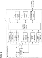
- Fig. 2 is a block diagram illustrating a configuration of the master apparatus 1 of Fig. 1 .
- the master apparatus 1 is provided with at least a master control circuit 10, a storage device 12, a signal level monitor 17, a signal receiving circuit 18, and an antenna device ANT1.
- the signal receiving circuit 18 wirelessly receives the measurement value of the sensor 23 from the slave apparatus 2 via the antenna device ANT1.
- the antenna device ANT1 and the signal level monitor 17 function as a position estimator configured to estimate the position of the slave apparatus 2 based on the signal received from the slave apparatus 2.
- the storage device 12 stores a history of the position of the slave apparatus 2 estimated using the antenna device ANT1 and the signal level monitor 17.
- the master control circuit 10 displays the measurement value of the sensor 23, and the position of the slave apparatus 2, on a display device 32.
- the display device 32 may be provided in a control apparatus 3 external to the master apparatus 1, for example, as illustrated in Fig. 1 .
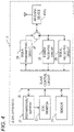
- Fig. 4 is a block diagram illustrating a configuration of the slave apparatus 2 of Fig. 1 .
- the slave apparatus 2 is provided with at least the sensor 23, a signal transmitting circuit 24, and an antenna device ANT2. As described above, the sensor 23 obtains the measurement value of the predetermined physical quantity.
- the signal transmitting circuit 24 wirelessly transmits the measurement value of the sensor 23 to the master apparatus 1 via the antenna device ANT2.
- the master control circuit 10 When the master control circuit 10 fails to receive the measurement value of the sensor 23 from the slave apparatus 2, the master control circuit 10 displays, on the display device 32, the latest position stored in the storage device 12, together with an error message indicating that the communication between the master apparatus 1 and the slave apparatus 2 is interrupted. As a result, even if the current position of the slave apparatus 2 is unknown due to the interruption of the communication, it is possible to provide a user with the position where the slave apparatus 2 is considered to reside. Therefore, it is possible to appropriately monitor the conditions and position of the slave apparatus to reduce burdens of maintenance and repair 2.
- the master apparatus 1 and the slave apparatus 2 may be configured and operate as follows.
- the master apparatus 1 may be additionally provided with a power transmitting circuit 14.
- the power transmitting circuit 14 wirelessly transmits power to the slave apparatus 2 via the antenna device ANT1.
- the slave apparatus 2 may be additionally provided with a power receiving circuit 25, a rechargeable battery 21, and a state-of-charge (SOC) monitor 22.
- the power receiving circuit 25 obtains power wirelessly transmitted from the master apparatus 1, via the antenna device ANT2.
- the rechargeable battery 21 stores the power wirelessly transmitted from the master apparatus 1.
- the state-of-charge monitor 22 measures a state of charge of the rechargeable battery 21.
- the signal transmitting circuit 24 of the slave apparatus 2 wirelessly transmits the state of charge of the rechargeable battery 21 to the master apparatus 1, as well as the measurement value of the sensor 23, via the antenna device ANT2.
- the signal receiving circuit 18 of the master apparatus 1 wirelessly receives the state of charge of the rechargeable battery 21, as well as the measurement value of the sensor 23, from the slave apparatus 2, via the antenna device ANT1.
- the storage device 12 stores a history of the measurement value of the sensor 23, in addition to or instead of the history of the position of the slave apparatus 2.
- the master control circuit 10 may operate as follows.
- the master control circuit 10 displays, on the display device 32, an error message indicating that the state of charge of the rechargeable battery 21 is low (i.e., insufficient).
- the threshold for the state of charge is set so that the rechargeable battery 21 can supply power not enough for the sensor 23 to operate, but enough for the slave control circuit 20 and the signal transmitting circuit 24 of the slave apparatus 2 to operate.
- the shortage of the state of charge may occur, for example, when the wireless power transmission from the master apparatus 1 to the slave apparatus 2 is interrupted, or when the rechargeable battery 21 and/or the power receiving circuit 25 are broken. Further, when the measurement value of the sensor 23 is unchanged for a predetermined time period, the master control circuit 10 displays, on the display device 32, an error message indicating that malfunction of the sensor 23 has occurred.
- the malfunction of the sensor 23 may occur, for example, when the sensor 23 is broken, or when the sensor 23 is not correctly installed (that is, when the sensor is installed at a position or in a posture in which the sensor can not measure a target to be measured.).
- the sensor 23 can not obtain the measurement value due to other failures (shortage of state of charge, or malfunction of the sensor 23). Even if the measurement value of the sensor 23 is unknown, it is possible to estimate the position of the slave apparatus 2 based on the signal received by the master apparatus 1 from the slave apparatus 2. Therefore, it is possible to appropriately monitor the conditions and position of the slave apparatus 2 to reduce burdens of maintenance and repair.
- the wireless communication system of the embodiment it is possible to appropriately monitor the conditions and position of the slave apparatus 2 to reduce the burdens of maintenance and repair.
- the master apparatus 1 and the slave apparatuses 2-1 to 2-3 are provided in a factory including a control apparatus 3, a manufacturing apparatus 4, and a belt conveyor 5.
- the belt conveyor 5 conveys pallets 6 and workpieces 7.
- the pallets 6 and the workpieces 7 are moved by the belt conveyor 5 so as to arrive at predetermined positions at predetermined times.
- a predetermined work event is performed on the workpiece 7.
- the slave apparatuses 2-1 to 2-3 are provided near the predetermined positions, respectively, and associated with the events performed at the predetermined positions, respectively.
- the sensors 23 of the slave apparatuses 2-1 to 2-3 measure predetermined physical quantities associated with these events.
- the master apparatus 1 collects the measured physical quantities from the slave apparatuses 2-1 to 2-3, and sends the physical quantities to the control apparatus 3.
- the control apparatus 3 controls operations of the manufacturing apparatus 4 based on the measured physical quantities.
- the control apparatus 3 is, for example, a programmable logic controller.
- the manufacturing apparatus 4 performs a predetermined work event (for example, a fabrication process, such as welding) on the workpieces 7.
- the master apparatus 1 is provided with the master control circuit 10, a power supply device 11, the storage device 12, a communication circuit 13, the power transmitting circuit 14, a signal transmitting circuit 15, an antenna control circuit 16, the signal level monitor 17, the signal receiving circuit 18, a circulator circuit 19, and an antenna device ANT1.
- the master control circuit 10 controls overall operations of the master apparatus 1.
- the power supply device 11 supplies power to be transmitted to the slave apparatus 2.
- the storage device 12 stores the history of the measurement value of the sensor 23, and the history of the position of the slave apparatus 2, as described above.
- the communication circuit 13 is connected to the control apparatus 3 via a wired or wireless communication line.
- the master control circuit 10 outputs the measurement value of the sensor 23, the position of the slave apparatus 2, and the error messages, to the control apparatus 3 via the communication circuit 13.
- the power transmitting circuit 14 wirelessly transmits power to the slave apparatus 2 via the circulator circuit 19 and the antenna device ANT1, for operating the sensor 23 and the other circuits of the slave apparatus 2.
- the power transmitting circuit 14 generates, for example, a continuous wave (CW) from the power supplied by the power supply device 11.
- CW continuous wave
- the signal transmitting circuit 15 wirelessly transmits control signals for controlling the sensor 23 (for example, a read signal of the sensor 23) to the slave apparatus 2 via the circulator circuit 19 and the antenna device ANT1.
- the antenna device ANT1 has variable directivity.
- the antenna control circuit 16 controls the directivity (directional pattern) of the antenna device ANT1 under the control of the master control circuit 10.
- the signal level monitor 17 measures a signal level of a signal wirelessly received from the slave apparatus 2, for example, a received signal strength indicator (RSSI).
- RSSI received signal strength indicator
- the signal receiving circuit 18 wirelessly receives a response signal from the slave apparatus 2 via the antenna device ANT1 and the circulator circuit 19, the response signal including the measurement value of the sensor 23, and the state of charge of the rechargeable battery 21.
- the circulator circuit 19 combines and separates power and signals transmitted to the slave apparatus 2 via the antenna device ANT1, with/from signals received from the slave apparatus 2 via the antenna device ANT1.
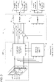
- Fig. 3 is a block diagram illustrating a detailed configuration of the circulator circuit 19 and the antenna device ANT1 of Fig. 2 .
- the antenna device ANT1 may be, for example, an array antenna including a plurality of antenna elements.
- the circulator circuit 19 is provided with a divider 41, circulators 42-1 to 42-4, and a combiner 43.
- the divider 41 divides the power sent from the power transmitting circuit 14 into four in accordance with the number of antenna elements. Similarly, the divider 41 divides the signal sent from the signal transmitting circuit 15 into four in accordance with the number of antenna elements.
- the circulators 42-1 to 42-4 send the power and signals divided by the divider 41 to the antenna device ANT1, and send the four signals sent from the antenna device ANT1 to the combiner 43.
- the combiner 43 combines the four signals sent from the antenna device ANT1 with each other, and sends the combined signal to the signal level monitor 17 and the signal receiving circuit 18.
- the antenna device ANT1 is provided with a phase and amplitude adjuster 51, and antenna elements 52-1 to 52-4.
- the antenna elements 52-1 to 52-4 are arranged at predetermined intervals.
- the phase and amplitude adjuster 51 adjusts phases and amplitudes of the signals transmitted and received via the antenna elements 52-1 to 52-4, under the control of the antenna control circuit 16, thus controlling the directions of a beam and a null of the antenna device ANT1.
- the slave apparatus 2 is provided with the slave control circuit 20, the rechargeable battery 21, the state-of-charge monitor 22, the sensor 23, the signal transmitting circuit 24, the power receiving circuit 25, a signal receiving circuit 26, a circulator circuit 27, and the antenna device ANT2.
- the slave control circuit 20 controls overall operations of the slave apparatus 2.
- the rechargeable battery 21 stores the power wirelessly transmitted from the master apparatus 1, as described above.
- the state-of-charge monitor 22 measures the state of charge of the rechargeable battery 21, as described above.
- the state-of-charge monitor 22 measures the state of charge of the rechargeable battery 21, for example, based on a charged voltage of the rechargeable battery 21.
- the sensor 23 obtains the measurement value of the predetermined physical quantity, as described above.
- the sensor 23 may measure any of physical quantities, for example, such as temperature, light, displacement, vibration, pressure, flow rate, inclination, and the like.
- the sensor 23 may detect a state of a target, for example, ON/OFF of a switch or apparatus, by obtaining a measurement value of a predetermined physical quantity.
- the signal transmitting circuit 24 wirelessly transmits a response signal to the master apparatus 1 via the circulator circuit 27 and the antenna device ANT2.
- the response signal including the measurement value of the sensor 23, and the state of charge of the rechargeable battery 21.
- the power receiving circuit 25 obtains power wirelessly transmitted from the master apparatus 1, via the antenna device ANT2 and the circulator circuit 27.
- the signal receiving circuit 26 wirelessly receives control signals including a read signal of the sensor 23 and the like, from the master apparatus 1, via the antenna device ANT2 and the circulator circuit 27.
- the antenna device ANT2 has a predetermined directional pattern or omni-directional pattern.
- the circulator circuit 27 combines and separates power and signals transmitted from the master apparatus 1 via the antenna device ANT2, with/from signals transmitted to the master apparatus 1 via the antenna device ANT2.
- Fig. 5 is a block diagram illustrating a configuration of the control apparatus 3 of Fig. 1 .
- the control apparatus 3 is provided with a system control circuit 30, a communication circuit 31, and a display device 32.
- the system control circuit 30 controls overall operations of the control apparatus 3, and controls overall operations of the manufacturing system of Fig. 1 .
- the communication circuit 31 is connected to the master apparatus 1 via a wired or wireless communication line. In addition, the communication circuit 31 is connected to the manufacturing apparatus 4 via a wired or wireless communication line.
- the system control circuit 30 sends a read request signal for requesting reading of the measurement value of the sensor 23, to the master apparatus 1 via the communication circuit 31. In addition, the system control circuit 30 receives the measurement value of the sensor 23, the position of the slave apparatus 2, and the error messages, from the master apparatus 1 via the communication circuit 31. In addition, the system control circuit 30 sends a control signal for controlling operations of the manufacturing apparatus 4, to the master apparatus 1 via the communication circuit 31.
- the display device 32 displays a state of the manufacturing system of Fig. 1 , for example, data received from the master apparatus 1, that is, the measurement value of the sensor 23, the position of the slave apparatus 2, and the error messages.
- the display device 32 may be integrated with the control apparatus 3, or may be connected externally to the control apparatus 3.
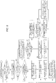
- Fig. 6 is a flowchart illustrating a master control process executed by the master control circuit 10 of Fig. 2 .
- step S1 the master control circuit 10 determines whether or not a read request signal is received from the control apparatus 3; if YES, the process proceeds to step S2, and if NO, the process repeats to step S1.
- step S2 the master control circuit 10 transmits a read signal to the slave apparatus 2 for obtaining the measurement value of the sensor 23.
- Fig. 7 is a flowchart illustrating a slave control process executed by the slave control circuit 20 of Fig. 4 .
- the slave control circuit 20 obtains the state of charge of the rechargeable battery 21 using the state-of-charge monitor 22.
- the slave control circuit 20 obtains the measurement value of the sensor 23.
- the slave control circuit 20 determines whether or not the read signal is received from the master apparatus 1; if YES, the process proceeds to step S24, and if NO, the process returns to step S21.
- step S24 the slave control circuit 20 transmits a response signal including the measurement value of the sensor 23 and the state of charge of the rechargeable battery 21, to the master apparatus 1.
- step S3 the master control circuit 10 determines whether or not the response signal is received from the slave apparatus 2; if YES, the process proceeds to step S8, and if NO, the process proceeds to step S4.
- the master control circuit 10 repeats steps S2 to S4 until receiving the response signal to the read signal transmitted in step S2.
- step S4 the master control circuit 10 determines whether or not the number of consecutive retries of steps S2 to S4 exceeds a predetermined threshold; if YES, the process proceeds to step S5, and if NO, the process returns to step S2.
- step S5 the master control circuit 10 reads the latest position of the slave apparatus 2 from the storage device 12.
- the position of the slave apparatus 2 read from the storage device 12 is the past position of the slave apparatus 2 estimated when the response signal is received from the slave apparatus 2.
- the measurement value of the sensor 23 is unknown. Therefore, in step S6, the master control circuit 10 generates a dummy measurement value of the sensor 23.
- step S7 the master control circuit 10 sets an error code indicating an error in communication between the master apparatus 1 and the slave apparatus 2.
- step S8 the master control circuit 10 estimates the position of the slave apparatus 2 based on the response signal received from the slave apparatus 2, and stores the estimated position in the storage device 12.
- the position of the slave apparatus 2 is estimated using the antenna device ANT1 and the signal level monitor 17, as described above.
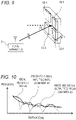
- Fig. 9 is a diagram for explaining estimation of the direction of the slave apparatus 2 as seen from the master apparatus 1 of Fig. 1 .
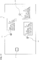
- Fig. 10 is a diagram for explaining estimation of a distance between the master apparatus 1 and the slave apparatus 2 of Fig. 1 .
- the signal level of a signal wirelessly received by the master apparatus 1 from the slave apparatus 2 decreases as the distance between the master apparatus 1 and the slave apparatus 2 increases, and increases as the distance decreases. Therefore, it is possible to estimate the distance between the master apparatus 1 and the slave apparatus 2, by using the signal level monitor 17 to measure the signal level (for example, RSSI) of the signal wirelessly received from the slave apparatus 2.
- the signal level of an individual received signal arrived at each of the antenna elements 52-1 to 52-4, before being inputted to the combiner 43 may be affected by multipath, and therefore, largely differ from an ideal signal level.
- the antenna device ANT1 and the antenna control circuit 16 are calibrated in advance so that the direction of the slave apparatus 2 as seen from the master apparatus 1 can be estimated.
- the signal level monitor 17 is calibrated in advance so that the distance between the master apparatus 1 and the slave apparatus 2 can be estimated.
- step S9 the master control circuit 10 determines whether or not the state of charge of the rechargeable battery 21 is equal to or higher than a predetermined threshold; if YES, the process proceeds to step S12, and if NO, the process proceeds to step S10.
- the threshold for the state of charge is set so that the rechargeable battery 21 can supply power not enough for the sensor 23 to operate, but enough for the slave control circuit 20 and the signal transmitting circuit 24 of the slave apparatus 2 to operate.
- step S9 If step S9 is NO, since the sensor 23 can not correctly operate due to the shortage of the state of charge, a correct measurement value of the sensor 23 can not be obtained. Therefore, in step S10, the master control circuit 10 generates a dummy measurement value of the sensor 23. In step S11, the master control circuit 10 sets an error code indicating a state-of-charge error.
- step S12 the master control circuit 10 obtains the measurement value of the sensor 23 from the response signal.
- step S13 the master control circuit 10 determines whether or not the measurement value of the sensor 23 is unchanged for a predetermined time period; if YES, the process proceeds to step S14, and if NO, the process proceeds to step S15.
- the time period of step S13 may be set to a predetermined time length, or may be set as the number of iterations of the master control process.
- step S14 the master control circuit 10 sets an error code indicating an error of the sensor 23.
- step S15 the master control circuit 10 generates an error code indicating that the communication, the state of charge, and the sensor 23 are normal (that is, there is no error).
- step S16 the master control circuit 10 sends the position of the slave apparatus 2, the measurement value of the sensor 23, and the error code, to the control apparatus 3. Thereafter, the process returns to step S1.
- Fig. 8 is a flowchart illustrating a system control process executed by the system control circuit 30 of Fig. 5 .
- step S31 the system control circuit 30 sends a read request signal to the master apparatus 1.
- step S32 the system control circuit 30 receives the position of the slave apparatus 2, the measurement value of the sensor 23, and the error code, from the master apparatus 1.
- step S33 the system control circuit 30 determines whether or not an error code indicating a communication error is received; if YES, the process proceeds to step S34, and if NO, the process proceeds to step S35.
- step S34 the system control circuit 30 displays the position of the slave apparatus 2, together with an error message indicating a communication error, on the display device 32.
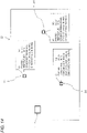
- Fig. 11 is a diagram illustrating exemplary arrangement of the master apparatus 1 and the slave apparatuses 2-1 to 2-3 displayed on the display device 32 of Fig. 1 , in which all the slave apparatuses 2-1 to 2-3 are normal.
- an identifier (ID) for example, a position
- a measurement value of the sensor 23 for example, temperature
- a state of communication for example, a state of charge
- a state of the operation of the sensor 23 are displayed in association with each of the slave apparatuses 2-1 to 2-3.
- the system control circuit 30 may display a map of a place where the wireless communication system is installed, and overlay the position of the master apparatus 1, and the estimated positions of the slave apparatuses 2, on the map.
- the system control circuit 30 may store the absolute position of the master apparatus 1 in advance. In this case, it is possible to estimate the absolute positions of the slave apparatuses 2 based on the absolute position of the master apparatus 1, and the estimated relative positions of the slave apparatuses 2.
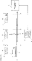
- Fig. 12 is a diagram illustrating exemplary arrangement of the master apparatus 1 and the slave apparatuses 2-1 to 2-3 displayed on the display device 32 of Fig. 1 , in which an error has occurred in communication between the master apparatus 1 and the slave apparatus 2-3. Due to the interruption of the communication, the current position of the slave apparatus 2, the measurement value of the sensor 23, the state of charge of the rechargeable battery 21, and the state of the operation of the sensor 23 are unknown.
- the display device 32 displays the latest position (x3', y3') of the slave apparatus 2 read from the storage device 12 of the master apparatus 1.
- step S35 the system control circuit 30 determines whether or not an error code indicating a state-of-charge error is received; if YES, the process proceeds to step S36, and if NO, the process proceeds to step S37.
- step S36 the system control circuit 30 displays the position of the slave apparatus 2, together with an error message indicating a state-of-charge error, on the display device 32.
- Fig. 13 is a diagram illustrating exemplary arrangement of the master apparatus 1 and the slave apparatuses 2-1 to 2-3 displayed on the display device 32 of Fig. 1 , in which an error has occurred in power transmission from the master apparatus 1 to the slave apparatus 2-3.
- the state of charge of the rechargeable battery 21 of the slave apparatus 2-3 becomes insufficient due to the error in power transmission.
- the display device 32 displays a dummy measurement value of the sensor 23 of the slave apparatus 2-3.
- step S37 the system control circuit 30 determines whether or not an error code indicating an error of the sensor 23 is received; if YES, the process proceeds to step S38, and if NO, the process proceeds to step S39.
- step S38 the system control circuit 30 displays the position of the slave apparatus 2, and the measurement value of the sensor 23, together with an error message indicating an error of the sensor 23, on the display device 32.
- step S39 the system control circuit 30 displays the position of the slave apparatus 2, and the measurement value of the sensor 23, on the display device 32.
- Fig. 14 is a diagram illustrating exemplary arrangement of the master apparatus 1 and the slave apparatuses 2-1 to 2-3 displayed on the display device 32 of Fig. 1 , in which an error has occurred in the operation of the sensor 23 of the slave apparatus 2-3. Malfunction occurs in the sensor 23 of the slave apparatus 2-3, but its current measurement value is considered to be equal to the correct measurement value obtained immediately before the malfunction occurs in the sensor 23. Therefore, the display device 32 displays the measurement value of the sensor 23 of the slave apparatus 2-3.
- the system control circuit 30 may control the operations of the manufacturing apparatus 4 under the control of a user, or may periodically repeat the process of Fig. 8 .
- the master control circuit 10 when the master control circuit 10 fails to receive the measurement value of the sensor 23 from the slave apparatus 2, the master control circuit 10 displays, on the display device 32, the latest position stored in the storage device 12, together with an error message indicating that the communication between the master apparatus 1 and the slave apparatus 2 is interrupted.
- the master control circuit 10 displays, on the display device 32, the latest position stored in the storage device 12, together with an error message indicating that the communication between the master apparatus 1 and the slave apparatus 2 is interrupted.
- the master control circuit 10 displays, on the display device 32, an error message indicating that the state of charge of the rechargeable battery 21 is low. Further, when the measurement value of the sensor 23 is unchanged for a predetermined time period, the master control circuit 10 displays, on the display device 32, an error message indicating that malfunction has occurred in the sensor 23.
- the sensor 23 can not obtain the measurement value due to other failures (shortage of state of charge, or malfunction of the sensor 23). Even if the measurement value of the sensor 23 is unknown, it is possible to estimate the position of the slave apparatus 2 based on the signal received by the master apparatus 1 from the slave apparatus 2.
- the wireless communication system of the first embodiment it is possible to appropriately monitor the conditions and position of the slave apparatus 2 to reduce the burdens of maintenance and repair.
- the wireless communication system of the first embodiment since the conditions and position of each of the slave apparatuses 2 can be displayed on the display device 32 in association with each other, it is possible to reduce the time and effort of maintenance and repair of the wireless communication system, and reduce the time and effort of set-up change of the manufacturing apparatus 4 and the like.
- maintenance and repair of the wireless communication system, the manufacturing apparatus 4, and others may be automated using a robot or the like operable based on the monitored conditions and position of each of the slave apparatuses 2.
- the received signals arriving at the antenna elements of the array antenna are combined with each other, and the distance between the master apparatus 1 and the slave apparatus 2 is estimated based on the signal level of the combined received signal. Therefore, it is possible to reduce the influence of the multipath, and estimate the distance with a small error.
- the wireless communication system of the first embodiment it is possible to integrate the system for wirelessly transmitting power from the master apparatus to the slave apparatus, with the function of detecting the position of the slave apparatus.
- Fig. 15 is a block diagram illustrating a manufacturing system including a wireless communication system according to a second embodiment.
- the system of Fig. 15 includes a master apparatus 1A, instead of the master apparatus 1 and the manufacturing apparatus 4 of Fig. 1 .
- the master apparatus 1A of Fig. 15 has the functions of the master apparatus 1 and the manufacturing apparatus 4 of Fig. 1 , and is provided with, for example, the display device 32 of Fig. 5 and other components.
- the display device 32 may be integrated with the master apparatus 1A, or may be connected externally to the master apparatus 1A.
- Each of the slave apparatuses 2 may be fixed to facilities of a factory or the like.
- each of the slave apparatuses 2 may be a mobile apparatus attached to a robot or the body of a user.
- the control apparatus 3 may control a plurality of master apparatuses 1.
- the signal level monitor 17 of Fig. 2 may be integrated to the signal receiving circuit 18.
- the signal receiving circuit 18 may measure the signal level of the received signal.
- the state of charge of the rechargeable battery 21 may be compared with a threshold by the master apparatus 1 or the slave apparatus 2. In the latter case, the slave apparatus 2 transmits the comparison result of the state of charge to the master apparatus 1.
- step S13 of Fig. 6 instead of determining whether or not the measurement value of the sensor 23 is unchanged for a predetermined time period, the master control circuit 10 may determine, for example, whether or not the measurement value of the sensor 23 is outside a predetermined range.
- the wireless communication apparatus and the wireless communication system according to the aspects of the present disclosure may be expressed as follows.
- a wireless communication apparatus is operable as a master apparatus 1 for a wireless communication system including the master apparatus 1 and at least one slave apparatus 2.
- the slave apparatus 2 is provided with a sensor 23 configured to obtain a measurement value of a predetermined physical quantity, and the slave apparatus 2 wirelessly transmits the measurement value of the sensor 23 to the wireless communication apparatus.
- the wireless communication apparatus is provided with: a signal receiving circuit 18 configured to wirelessly receive the measurement value of the sensor 23 from the slave apparatus 2; a position estimator configured to estimate a position of the slave apparatus 2; a storage device 12 configured to store a history of the position of the slave apparatus 2; and a master control circuit 10 configured to display the measurement value of the sensor 23 and the position of the slave apparatus 2 on a display device 32.
- the master control circuit 10 When the master control circuit 10 fails to receive the measurement value of the sensor 23 from the slave apparatus 2, the master control circuit 10 displays, on the display device 32, a latest position stored in the storage device 12, together with an error message indicating that communication between the wireless communication apparatus and the slave apparatus 2 is interrupted.
- the storage device 12 stores a history of the measurement value of the sensor 23.
- the master control circuit 10 displays, on the display device 32, an error message indicating that malfunction of the sensor 23 has occurred.
- the wireless communication apparatus is further provided with a power transmitting circuit 14 configured to wirelessly transmit power to the slave apparatus 2.
- the slave apparatus 2 is provided with a rechargeable battery 21 configured to store the power wirelessly transmitted from the wireless communication apparatus, and the slave apparatus 2 measures a state of charge of the rechargeable battery 21, and wirelessly transmits the state of charge to the wireless communication apparatus.
- the signal receiving circuit 18 wirelessly receives the state of charge of the rechargeable battery 21 from the slave apparatus 2.
- the master control circuit 10 displays, on the display device 32, an error message indicating that the state of charge of the rechargeable battery 21 is low.
- a wireless communication apparatus is operable as a master apparatus 1 for a wireless communication system including the master apparatus 1 and at least one slave apparatus 2.
- the slave apparatus 2 is provided with a rechargeable battery 21 storing power wirelessly transmitted from the wireless communication apparatus, measures a state of charge of the rechargeable battery 21, and wirelessly transmits the state of charge to the wireless communication apparatus.
- the slave apparatus 2 is provided with a sensor 23 configured to obtain a measurement value of a predetermined physical quantity, and the slave apparatus 2 wirelessly transmits the measurement value of the sensor 23 to the wireless communication apparatus.
- the wireless communication apparatus is provided with: a power transmitting circuit 14 configured to wirelessly transmit power to the slave apparatus 2; a signal receiving circuit 18 configured to wirelessly receive the state of charge of the rechargeable battery 21, and the measurement value of the sensor 23, from the slave apparatus 2; a position estimator configured to estimate a position of the slave apparatus 2; a storage device 12 configured to store a history of the measurement value of the sensor 23; and a master control circuit 10 configured to display the measurement value of the sensor 23, and the position of the slave apparatus 2, on a display device 32.
- the master control circuit 10 displays, on the display device 32, an error message indicating that the state of charge of the rechargeable battery 21 is low.
- the master control circuit 10 displays, on the display device 32, an error message indicating that malfunction of the sensor 23 has occurred.
- the position estimator is provided with: an antenna device ANT1 having variable directivity; and a signal level monitor 17 configured to measure a signal level of a signal wirelessly received from the slave apparatus 2.
- a wireless communication system includes: the wireless communication apparatus of one of the first to fifth aspects; and at least one slave apparatus 2.
- the wireless communication system further includes a control apparatus 3 provided with a display device 32.
- the wireless communication apparatus is communicatively coupled to the control apparatus 3.
- the wireless communication system can be used for, for example, a sensor network including a plurality of sensors.
Landscapes
- Engineering & Computer Science (AREA)
- Computer Networks & Wireless Communication (AREA)
- Signal Processing (AREA)
- Mobile Radio Communication Systems (AREA)
- Arrangements For Transmission Of Measured Signals (AREA)
- Position Fixing By Use Of Radio Waves (AREA)
- Selective Calling Equipment (AREA)
Abstract
Description
- The present disclosure relates to a wireless communication apparatus operable as a master apparatus for a wireless communication system including the master apparatus and at least one slave apparatus, and also relates to a wireless communication system including such a wireless communication apparatus.
- A sensor network including a plurality of sensors arranged at various positions may be constructed using a wireless communication system including a plurality of slave apparatuses each having a sensor, and a master apparatus wirelessly communicatively coupled to the slave apparatuses. Each of the sensors obtains a measurement value of a predetermined physical quantity, and the master apparatus reads the sensor's measurement value from each of the slave apparatuses.
- For example,
Patent Document 1 discloses a network system including a plurality of node apparatuses, and sensor apparatuses connected to the node apparatuses via wireless or wired communication, and a method for transmitting and receiving sensor data. - PATENT DOCUMENT 1: Japanese Patent Laid-open Publication No.
JP 2013-098926 A - In such a wireless communication system, the master apparatus may fail to obtain a certain sensor's measurement value due to some failure. Such an event may occur due to the sensor's failure, and may also occur due to an interruption in communication between the master apparatus and the slave apparatus. Therefore, it takes time and effort to specify a target to be repaired. In addition, the position of the slave apparatus is not always known. In this case, it takes time and effort to specify the position of the slave apparatus (sensor) to be repaired. Therefore, it is required to appropriately monitor conditions and position of the slave apparatus to reduce burdens of maintenance and repair.
- An object of the present disclosure is to provide a wireless communication apparatus capable of appropriately monitoring conditions and position of a slave apparatus to reduce burdens of maintenance and repair. In addition, another object of the present disclosure is to provide a wireless communication system including such a wireless communication apparatus.
- According to an aspect of the present disclosure, a wireless communication apparatus is operable as a master apparatus for a wireless communication system including the master apparatus and at least one slave apparatus. The slave apparatus is provided with a sensor configured to obtain a measurement value of a predetermined physical quantity, and the slave apparatus wirelessly transmits the measurement value of the sensor to the wireless communication apparatus. The wireless communication apparatus is provided with: a signal receiving circuit configured to wirelessly receive the measurement value of the sensor from the slave apparatus; a position estimator configured to estimate a position of the slave apparatus; a storage device configured to store a history of the position of the slave apparatus; and a master control circuit configured to display the measurement value of the sensor and the position of the slave apparatus on a display device. When the master control circuit fails to receive the measurement value of the sensor from the slave apparatus, the master control circuit displays, on the display device, a latest position stored in the storage device, together with an error message indicating that communication between the wireless communication apparatus and the slave apparatus is interrupted.
- With this configuration, even if the current position of the slave apparatus is unknown due to the interruption of the communication, it is possible to provide a user with the position where the slave apparatus is considered to reside. Therefore, it is possible to appropriately monitor the conditions and position of the slave apparatus to reduce burdens of maintenance and repair.
- According to an aspect of the present disclosure, the storage device stores a history of the measurement value of the sensor. When the measurement value of the sensor is unchanged for a predetermined time period, the master control circuit displays, on the display device, an error message indicating that malfunction of the sensor has occurred.
- With this configuration, it can be seen that although the master apparatus and the slave apparatus can communicate with each other, the sensor can not obtain the measurement value due to malfunction of the sensor.
- According to an aspect of the present disclosure, the wireless communication apparatus is further provided with a power transmitting circuit configured to wirelessly transmit power to the slave apparatus. The slave apparatus is provided with a rechargeable battery configured to store the power wirelessly transmitted from the wireless communication apparatus, and the slave apparatus measures a state of charge of the rechargeable battery, and wirelessly transmits the state of charge to the wireless communication apparatus. The signal receiving circuit wirelessly receives the state of charge of the rechargeable battery from the slave apparatus. When the state of charge of the rechargeable battery is smaller than a predetermined threshold, the master control circuit displays, on the display device, an error message indicating that the state of charge of the rechargeable battery is low.
- With this configuration, it can be seen that although the master apparatus and the slave apparatus can communicate with each other, the sensor can not obtain the measurement value due to shortage of the state of charge.
- According to an aspect of the present disclosure, a wireless communication apparatus is operable as a master apparatus for a wireless communication system including the master apparatus and at least one slave apparatus. The slave apparatus is provided with a rechargeable battery storing power wirelessly transmitted from the wireless communication apparatus, measures a state of charge of the rechargeable battery, and wirelessly transmits the state of charge to the wireless communication apparatus. The slave apparatus is provided with a sensor configured to obtain a measurement value of a predetermined physical quantity, and the slave apparatus wirelessly transmits the measurement value of the sensor to the wireless communication apparatus. The wireless communication apparatus is provided with: a power transmitting circuit configured to wirelessly transmit power to the slave apparatus; a signal receiving circuit configured to wirelessly receive the state of charge of the rechargeable battery, and the measurement value of the sensor, from the slave apparatus; a position estimator configured to estimate a position of the slave apparatus; a storage device configured to store a history of the measurement value of the sensor; and a master control circuit configured to display the measurement value of the sensor, and the position of the slave apparatus, on a display device. When the state of charge of the rechargeable battery is smaller than a predetermined threshold, the master control circuit displays, on the display device, an error message indicating that the state of charge of the rechargeable battery is low. When the measurement value of the sensor is unchanged for a predetermined time period, the master control circuit displays, on the display device, an error message indicating that malfunction of the sensor has occurred.
- With this configuration, it can be seen that although the master apparatus and the slave apparatus can communicate with each other, the sensor can not obtain the measurement value due to other failures (shortage of state of charge, or malfunction of the sensor). Therefore, it is possible to appropriately monitor the conditions and position of the slave apparatus to reduce burdens of maintenance and repair.
- According to an aspect of the present disclosure, the position estimator is provided with: an antenna device having variable directivity; and a signal level monitor configured to measure a signal level of a signal wirelessly received from the slave apparatus.
- With this configuration, it is possible to estimate the direction of the slave apparatus as seen from the master apparatus, and estimate the distance between the master apparatus and the slave apparatus,
- According to an aspect of the present disclosure, a wireless communication system includes: the wireless communication apparatus according to any one of
claims 1 to 5; and at least one slave apparatus. - With this configuration, it is possible to appropriately monitor the conditions and position of the slave apparatus to reduce burdens of maintenance and repair.
- According to an aspect of the present disclosure, the wireless communication system further includes a control apparatus provided with a display device. The wireless communication apparatus is communicatively coupled to the control apparatus.
- With this configuration, it is possible to display the conditions and position of the slave apparatus in association with each other
- According to the wireless communication apparatus and the wireless communication system according to the aspects of the present disclosure, it is possible to appropriately monitor the conditions and position of the slave apparatus to reduce the burdens of maintenance and repair.
-
-
Fig. 1 is a block diagram illustrating a manufacturing system including a wireless communication system according to a first embodiment. -
Fig. 2 is a block diagram illustrating a configuration of amaster apparatus 1 ofFig. 1 . -
Fig. 3 is a block diagram illustrating a detailed configuration of acirculator circuit 19 and an antenna device ANT1 ofFig. 2 . -
Fig. 4 is a block diagram illustrating a configuration of aslave apparatus 2 ofFig. 1 . -
Fig. 5 is a block diagram illustrating a configuration of acontrol apparatus 3 ofFig. 1 . -
Fig. 6 is a flowchart illustrating a master control process executed by amaster control circuit 10 ofFig. 2 . -
Fig. 7 is a flowchart illustrating a slave control process executed by aslave control circuit 20 ofFig. 4 . -
Fig. 8 is a flowchart illustrating a system control process executed by asystem control circuit 30 ofFig. 5 . -
Fig. 9 is a diagram for explaining estimation of a direction of theslave apparatus 2 as seen from themaster apparatus 1 ofFig. 1 . -
Fig. 10 is a diagram for explaining estimation of a distance between themaster apparatus 1 and theslave apparatus 2 ofFig. 1 . -
Fig. 11 is a diagram illustrating exemplary arrangement of themaster apparatus 1 and slave apparatuses 2-1 to 2-3 displayed on adisplay device 32 ofFig. 1 , in which all the slave apparatuses 2-1 to 2-3 are normal. -
Fig. 12 is a diagram illustrating exemplary arrangement of themaster apparatus 1 and the slave apparatuses 2-1 to 2-3 displayed on thedisplay device 32 ofFig. 1 , in which an error has occurred in communication between themaster apparatus 1 and the slave apparatus 2-3. -
Fig. 13 is a diagram illustrating exemplary arrangement of themaster apparatus 1 and the slave apparatuses 2-1 to 2-3 displayed on thedisplay device 32 ofFig. 1 , in which an error has occurred in power transmission from themaster apparatus 1 to the slave apparatus 2-3. -
Fig. 14 is a diagram illustrating exemplary arrangement of themaster apparatus 1 and the slave apparatuses 2-1 to 2-3 displayed on thedisplay device 32 ofFig. 1 , in which an error has occurred in operation of asensor 23 of the slave apparatus 2-3. -
Fig. 15 is a block diagram illustrating a manufacturing system including a wireless communication system according to a second embodiment. - Hereinafter, embodiments according to one aspect of the present disclosure (hereinafter, also referred to as "the present embodiments") will be described with reference to the drawings. In the drawings, the same reference sign indicates similar components.
-
Fig. 1 is a block diagram illustrating a manufacturing system including a wireless communication system according to a first embodiment. The wireless communication system ofFig. 1 includes amaster apparatus 1, and at least one slave apparatus, in the example inFig. 1 , three slave apparatuses 2-1 to 2-3. - In the present specification, the slave apparatuses 2-1 to 2-3 are collectively referred to as "
slave apparatuses 2". - As will be described later, each of the
slave apparatuses 2 is provided with asensor 23 configured to obtain a measurement value of a predetermined physical quantity, and wirelessly transmits the measurement value of thesensor 23 to themaster apparatus 1. -
Fig. 2 is a block diagram illustrating a configuration of themaster apparatus 1 ofFig. 1 . Themaster apparatus 1 is provided with at least amaster control circuit 10, astorage device 12, asignal level monitor 17, asignal receiving circuit 18, and an antenna device ANT1. Thesignal receiving circuit 18 wirelessly receives the measurement value of thesensor 23 from theslave apparatus 2 via the antenna device ANT1. The antenna device ANT1 and the signal level monitor 17 function as a position estimator configured to estimate the position of theslave apparatus 2 based on the signal received from theslave apparatus 2. Thestorage device 12 stores a history of the position of theslave apparatus 2 estimated using the antenna device ANT1 and thesignal level monitor 17. Themaster control circuit 10 displays the measurement value of thesensor 23, and the position of theslave apparatus 2, on adisplay device 32. Thedisplay device 32 may be provided in acontrol apparatus 3 external to themaster apparatus 1, for example, as illustrated inFig. 1 . -
Fig. 4 is a block diagram illustrating a configuration of theslave apparatus 2 ofFig. 1 . Theslave apparatus 2 is provided with at least thesensor 23, asignal transmitting circuit 24, and an antenna device ANT2. As described above, thesensor 23 obtains the measurement value of the predetermined physical quantity. Thesignal transmitting circuit 24 wirelessly transmits the measurement value of thesensor 23 to themaster apparatus 1 via the antenna device ANT2. - When the
master control circuit 10 fails to receive the measurement value of thesensor 23 from theslave apparatus 2, themaster control circuit 10 displays, on thedisplay device 32, the latest position stored in thestorage device 12, together with an error message indicating that the communication between themaster apparatus 1 and theslave apparatus 2 is interrupted. As a result, even if the current position of theslave apparatus 2 is unknown due to the interruption of the communication, it is possible to provide a user with the position where theslave apparatus 2 is considered to reside. Therefore, it is possible to appropriately monitor the conditions and position of the slave apparatus to reduce burdens of maintenance andrepair 2. - Additionally or alternatively, the
master apparatus 1 and theslave apparatus 2 may be configured and operate as follows. - As illustrated in
Fig. 2 , themaster apparatus 1 may be additionally provided with apower transmitting circuit 14. Thepower transmitting circuit 14 wirelessly transmits power to theslave apparatus 2 via the antenna device ANT1. - As illustrated in
Fig. 4 , theslave apparatus 2 may be additionally provided with apower receiving circuit 25, arechargeable battery 21, and a state-of-charge (SOC) monitor 22. Thepower receiving circuit 25 obtains power wirelessly transmitted from themaster apparatus 1, via the antenna device ANT2. Therechargeable battery 21 stores the power wirelessly transmitted from themaster apparatus 1. The state-of-charge monitor 22 measures a state of charge of therechargeable battery 21. In addition, thesignal transmitting circuit 24 of theslave apparatus 2 wirelessly transmits the state of charge of therechargeable battery 21 to themaster apparatus 1, as well as the measurement value of thesensor 23, via the antenna device ANT2. - The
signal receiving circuit 18 of themaster apparatus 1 wirelessly receives the state of charge of therechargeable battery 21, as well as the measurement value of thesensor 23, from theslave apparatus 2, via the antenna device ANT1. Thestorage device 12 stores a history of the measurement value of thesensor 23, in addition to or instead of the history of the position of theslave apparatus 2. - As described above, in addition to or instead of displaying the error message indicating that the communication is interrupted, and the stored latest position, on the
display device 32, themaster control circuit 10 may operate as follows. When the state of charge of therechargeable battery 21 is smaller than a predetermined threshold, themaster control circuit 10 displays, on thedisplay device 32, an error message indicating that the state of charge of therechargeable battery 21 is low (i.e., insufficient). The threshold for the state of charge is set so that therechargeable battery 21 can supply power not enough for thesensor 23 to operate, but enough for theslave control circuit 20 and thesignal transmitting circuit 24 of theslave apparatus 2 to operate. The shortage of the state of charge may occur, for example, when the wireless power transmission from themaster apparatus 1 to theslave apparatus 2 is interrupted, or when therechargeable battery 21 and/or thepower receiving circuit 25 are broken. Further, when the measurement value of thesensor 23 is unchanged for a predetermined time period, themaster control circuit 10 displays, on thedisplay device 32, an error message indicating that malfunction of thesensor 23 has occurred. The malfunction of thesensor 23 may occur, for example, when thesensor 23 is broken, or when thesensor 23 is not correctly installed (that is, when the sensor is installed at a position or in a posture in which the sensor can not measure a target to be measured.). As a result, it can be seen that although themaster apparatus 1 and theslave apparatus 2 can communicate with each other, thesensor 23 can not obtain the measurement value due to other failures (shortage of state of charge, or malfunction of the sensor 23). Even if the measurement value of thesensor 23 is unknown, it is possible to estimate the position of theslave apparatus 2 based on the signal received by themaster apparatus 1 from theslave apparatus 2. Therefore, it is possible to appropriately monitor the conditions and position of theslave apparatus 2 to reduce burdens of maintenance and repair. - As described above, according to the wireless communication system of the embodiment, it is possible to appropriately monitor the conditions and position of the
slave apparatus 2 to reduce the burdens of maintenance and repair. - In the example in
Fig. 1 , themaster apparatus 1 and the slave apparatuses 2-1 to 2-3 are provided in a factory including acontrol apparatus 3, amanufacturing apparatus 4, and abelt conveyor 5. Thebelt conveyor 5 conveyspallets 6 andworkpieces 7. Thepallets 6 and theworkpieces 7 are moved by thebelt conveyor 5 so as to arrive at predetermined positions at predetermined times. At each of the predetermined positions, a predetermined work event is performed on theworkpiece 7. The slave apparatuses 2-1 to 2-3 are provided near the predetermined positions, respectively, and associated with the events performed at the predetermined positions, respectively. Thesensors 23 of the slave apparatuses 2-1 to 2-3 measure predetermined physical quantities associated with these events. Themaster apparatus 1 collects the measured physical quantities from the slave apparatuses 2-1 to 2-3, and sends the physical quantities to thecontrol apparatus 3. Thecontrol apparatus 3 controls operations of themanufacturing apparatus 4 based on the measured physical quantities. Thecontrol apparatus 3 is, for example, a programmable logic controller. Themanufacturing apparatus 4 performs a predetermined work event (for example, a fabrication process, such as welding) on theworkpieces 7. - Referring to
Fig. 2 , themaster apparatus 1 is provided with themaster control circuit 10, apower supply device 11, thestorage device 12, acommunication circuit 13, thepower transmitting circuit 14, asignal transmitting circuit 15, anantenna control circuit 16, thesignal level monitor 17, thesignal receiving circuit 18, acirculator circuit 19, and an antenna device ANT1. - The
master control circuit 10 controls overall operations of themaster apparatus 1. - The
power supply device 11 supplies power to be transmitted to theslave apparatus 2. - The
storage device 12 stores the history of the measurement value of thesensor 23, and the history of the position of theslave apparatus 2, as described above. - The
communication circuit 13 is connected to thecontrol apparatus 3 via a wired or wireless communication line. Themaster control circuit 10 outputs the measurement value of thesensor 23, the position of theslave apparatus 2, and the error messages, to thecontrol apparatus 3 via thecommunication circuit 13. - The
power transmitting circuit 14 wirelessly transmits power to theslave apparatus 2 via thecirculator circuit 19 and the antenna device ANT1, for operating thesensor 23 and the other circuits of theslave apparatus 2. Thepower transmitting circuit 14 generates, for example, a continuous wave (CW) from the power supplied by thepower supply device 11. - The
signal transmitting circuit 15 wirelessly transmits control signals for controlling the sensor 23 (for example, a read signal of the sensor 23) to theslave apparatus 2 via thecirculator circuit 19 and the antenna device ANT1. - The antenna device ANT1 has variable directivity. The
antenna control circuit 16 controls the directivity (directional pattern) of the antenna device ANT1 under the control of themaster control circuit 10. - The signal level monitor 17 measures a signal level of a signal wirelessly received from the
slave apparatus 2, for example, a received signal strength indicator (RSSI). - The
signal receiving circuit 18 wirelessly receives a response signal from theslave apparatus 2 via the antenna device ANT1 and thecirculator circuit 19, the response signal including the measurement value of thesensor 23, and the state of charge of therechargeable battery 21. - The
circulator circuit 19 combines and separates power and signals transmitted to theslave apparatus 2 via the antenna device ANT1, with/from signals received from theslave apparatus 2 via the antenna device ANT1. -
Fig. 3 is a block diagram illustrating a detailed configuration of thecirculator circuit 19 and the antenna device ANT1 ofFig. 2 . The antenna device ANT1 may be, for example, an array antenna including a plurality of antenna elements. - The
circulator circuit 19 is provided with adivider 41, circulators 42-1 to 42-4, and acombiner 43. Thedivider 41 divides the power sent from thepower transmitting circuit 14 into four in accordance with the number of antenna elements. Similarly, thedivider 41 divides the signal sent from thesignal transmitting circuit 15 into four in accordance with the number of antenna elements. The circulators 42-1 to 42-4 send the power and signals divided by thedivider 41 to the antenna device ANT1, and send the four signals sent from the antenna device ANT1 to thecombiner 43. Thecombiner 43 combines the four signals sent from the antenna device ANT1 with each other, and sends the combined signal to thesignal level monitor 17 and thesignal receiving circuit 18. - The antenna device ANT1 is provided with a phase and
amplitude adjuster 51, and antenna elements 52-1 to 52-4. The antenna elements 52-1 to 52-4 are arranged at predetermined intervals. The phase andamplitude adjuster 51 adjusts phases and amplitudes of the signals transmitted and received via the antenna elements 52-1 to 52-4, under the control of theantenna control circuit 16, thus controlling the directions of a beam and a null of the antenna device ANT1. - Referring to
Fig. 4 , theslave apparatus 2 is provided with theslave control circuit 20, therechargeable battery 21, the state-of-charge monitor 22, thesensor 23, thesignal transmitting circuit 24, thepower receiving circuit 25, asignal receiving circuit 26, acirculator circuit 27, and the antenna device ANT2. - The
slave control circuit 20 controls overall operations of theslave apparatus 2. - The
rechargeable battery 21 stores the power wirelessly transmitted from themaster apparatus 1, as described above. - The state-of-
charge monitor 22 measures the state of charge of therechargeable battery 21, as described above. The state-of-charge monitor 22 measures the state of charge of therechargeable battery 21, for example, based on a charged voltage of therechargeable battery 21. - The
sensor 23 obtains the measurement value of the predetermined physical quantity, as described above. Thesensor 23 may measure any of physical quantities, for example, such as temperature, light, displacement, vibration, pressure, flow rate, inclination, and the like. In addition, thesensor 23 may detect a state of a target, for example, ON/OFF of a switch or apparatus, by obtaining a measurement value of a predetermined physical quantity. - The
signal transmitting circuit 24 wirelessly transmits a response signal to themaster apparatus 1 via thecirculator circuit 27 and the antenna device ANT2. the response signal including the measurement value of thesensor 23, and the state of charge of therechargeable battery 21. - The
power receiving circuit 25 obtains power wirelessly transmitted from themaster apparatus 1, via the antenna device ANT2 and thecirculator circuit 27. - The
signal receiving circuit 26 wirelessly receives control signals including a read signal of thesensor 23 and the like, from themaster apparatus 1, via the antenna device ANT2 and thecirculator circuit 27. - The antenna device ANT2 has a predetermined directional pattern or omni-directional pattern.
- The
circulator circuit 27 combines and separates power and signals transmitted from themaster apparatus 1 via the antenna device ANT2, with/from signals transmitted to themaster apparatus 1 via the antenna device ANT2. -
Fig. 5 is a block diagram illustrating a configuration of thecontrol apparatus 3 ofFig. 1 . Thecontrol apparatus 3 is provided with asystem control circuit 30, acommunication circuit 31, and adisplay device 32. - The
system control circuit 30 controls overall operations of thecontrol apparatus 3, and controls overall operations of the manufacturing system ofFig. 1 . - The
communication circuit 31 is connected to themaster apparatus 1 via a wired or wireless communication line. In addition, thecommunication circuit 31 is connected to themanufacturing apparatus 4 via a wired or wireless communication line. Thesystem control circuit 30 sends a read request signal for requesting reading of the measurement value of thesensor 23, to themaster apparatus 1 via thecommunication circuit 31. In addition, thesystem control circuit 30 receives the measurement value of thesensor 23, the position of theslave apparatus 2, and the error messages, from themaster apparatus 1 via thecommunication circuit 31. In addition, thesystem control circuit 30 sends a control signal for controlling operations of themanufacturing apparatus 4, to themaster apparatus 1 via thecommunication circuit 31. - The
display device 32 displays a state of the manufacturing system ofFig. 1 , for example, data received from themaster apparatus 1, that is, the measurement value of thesensor 23, the position of theslave apparatus 2, and the error messages. Thedisplay device 32 may be integrated with thecontrol apparatus 3, or may be connected externally to thecontrol apparatus 3. -
Fig. 6 is a flowchart illustrating a master control process executed by themaster control circuit 10 ofFig. 2 . - In step S1, the
master control circuit 10 determines whether or not a read request signal is received from thecontrol apparatus 3; if YES, the process proceeds to step S2, and if NO, the process repeats to step S1. - In step S2, the
master control circuit 10 transmits a read signal to theslave apparatus 2 for obtaining the measurement value of thesensor 23. -
Fig. 7 is a flowchart illustrating a slave control process executed by theslave control circuit 20 ofFig. 4 . In step S21, theslave control circuit 20 obtains the state of charge of therechargeable battery 21 using the state-of-charge monitor 22. In step S22, theslave control circuit 20 obtains the measurement value of thesensor 23. In step S23, theslave control circuit 20 determines whether or not the read signal is received from themaster apparatus 1; if YES, the process proceeds to step S24, and if NO, the process returns to step S21. In step S24, theslave control circuit 20 transmits a response signal including the measurement value of thesensor 23 and the state of charge of therechargeable battery 21, to themaster apparatus 1. - Referring again to
Fig. 6 , in step S3, themaster control circuit 10 determines whether or not the response signal is received from theslave apparatus 2; if YES, the process proceeds to step S8, and if NO, the process proceeds to step S4. - The
master control circuit 10 repeats steps S2 to S4 until receiving the response signal to the read signal transmitted in step S2. In step S4, themaster control circuit 10 determines whether or not the number of consecutive retries of steps S2 to S4 exceeds a predetermined threshold; if YES, the process proceeds to step S5, and if NO, the process returns to step S2. - In step S5, the
master control circuit 10 reads the latest position of theslave apparatus 2 from thestorage device 12. In this case, the position of theslave apparatus 2 read from thestorage device 12 is the past position of theslave apparatus 2 estimated when the response signal is received from theslave apparatus 2. In addition, since the response signal is not received from theslave apparatus 2, the measurement value of thesensor 23 is unknown. Therefore, in step S6, themaster control circuit 10 generates a dummy measurement value of thesensor 23. In step S7, themaster control circuit 10 sets an error code indicating an error in communication between themaster apparatus 1 and theslave apparatus 2. - In step S8, the
master control circuit 10 estimates the position of theslave apparatus 2 based on the response signal received from theslave apparatus 2, and stores the estimated position in thestorage device 12. The position of theslave apparatus 2 is estimated using the antenna device ANT1 and thesignal level monitor 17, as described above. -
Fig. 9 is a diagram for explaining estimation of the direction of theslave apparatus 2 as seen from themaster apparatus 1 ofFig. 1 . By steering the beam of the antenna device ANT1 to theslave apparatus 2, it is possible to estimate the direction of theslave apparatus 2 as seen from themaster apparatus 1. As illustrated inFig. 9 , it is possible to estimate at least one of the incident angle θ and the azimuth angle φ of the signal arriving from theslave apparatus 2 to themaster apparatus 1, depending on the structure of the antenna device ANT1 (for example, the arrangement of the antenna elements 52-1 to 52-4). Any algorithm can be used to steer the beam of the antenna device ANT1. -
Fig. 10 is a diagram for explaining estimation of a distance between themaster apparatus 1 and theslave apparatus 2 ofFig. 1 . In general, the signal level of a signal wirelessly received by themaster apparatus 1 from theslave apparatus 2 decreases as the distance between themaster apparatus 1 and theslave apparatus 2 increases, and increases as the distance decreases. Therefore, it is possible to estimate the distance between themaster apparatus 1 and theslave apparatus 2, by using the signal level monitor 17 to measure the signal level (for example, RSSI) of the signal wirelessly received from theslave apparatus 2. In this case, as illustrated inFig. 10 , the signal level of an individual received signal arrived at each of the antenna elements 52-1 to 52-4, before being inputted to thecombiner 43, may be affected by multipath, and therefore, largely differ from an ideal signal level. On the other hand, by combining these received signals using thecombiner 43, it is possible to reduce the influence of the multipath, and make the received signals close to ideal received signals. Therefore, by estimating the distance between themaster apparatus 1 and theslave apparatus 2 based on the signal level of the received signal outputted from thecombiner 43, is possible to estimate the distance with a smaller error than that of estimation based on the signal levels of the received signals to be inputted to thecombiner 43. - The antenna device ANT1 and the
antenna control circuit 16 are calibrated in advance so that the direction of theslave apparatus 2 as seen from themaster apparatus 1 can be estimated. In addition, the signal level monitor 17 is calibrated in advance so that the distance between themaster apparatus 1 and theslave apparatus 2 can be estimated. - Using the method as described with reference to
Figs. 9 and 10 , it is possible to estimate the relative position of theslave apparatus 2 as seen from themaster apparatus 1. If the absolute position of themaster apparatus 1 is known, it is possible to estimate the absolute position of theslave apparatus 2. - Referring again to
Fig. 6 , in step S9, themaster control circuit 10 determines whether or not the state of charge of therechargeable battery 21 is equal to or higher than a predetermined threshold; if YES, the process proceeds to step S12, and if NO, the process proceeds to step S10. As described above, the threshold for the state of charge is set so that therechargeable battery 21 can supply power not enough for thesensor 23 to operate, but enough for theslave control circuit 20 and thesignal transmitting circuit 24 of theslave apparatus 2 to operate. - If step S9 is NO, since the
sensor 23 can not correctly operate due to the shortage of the state of charge, a correct measurement value of thesensor 23 can not be obtained. Therefore, in step S10, themaster control circuit 10 generates a dummy measurement value of thesensor 23. In step S11, themaster control circuit 10 sets an error code indicating a state-of-charge error. - In step S12, the
master control circuit 10 obtains the measurement value of thesensor 23 from the response signal. In step S13, themaster control circuit 10 determines whether or not the measurement value of thesensor 23 is unchanged for a predetermined time period; if YES, the process proceeds to step S14, and if NO, the process proceeds to step S15. In this case, the time period of step S13 may be set to a predetermined time length, or may be set as the number of iterations of the master control process. - In step S14, the
master control circuit 10 sets an error code indicating an error of thesensor 23. - In step S15, the
master control circuit 10 generates an error code indicating that the communication, the state of charge, and thesensor 23 are normal (that is, there is no error). - In step S16, the
master control circuit 10 sends the position of theslave apparatus 2, the measurement value of thesensor 23, and the error code, to thecontrol apparatus 3. Thereafter, the process returns to step S1. -
Fig. 8 is a flowchart illustrating a system control process executed by thesystem control circuit 30 ofFig. 5 . - In step S31, the
system control circuit 30 sends a read request signal to themaster apparatus 1. In step S32, thesystem control circuit 30 receives the position of theslave apparatus 2, the measurement value of thesensor 23, and the error code, from themaster apparatus 1. - In step S33, the
system control circuit 30 determines whether or not an error code indicating a communication error is received; if YES, the process proceeds to step S34, and if NO, the process proceeds to step S35. In step S34, thesystem control circuit 30 displays the position of theslave apparatus 2, together with an error message indicating a communication error, on thedisplay device 32. -
Fig. 11 is a diagram illustrating exemplary arrangement of themaster apparatus 1 and the slave apparatuses 2-1 to 2-3 displayed on thedisplay device 32 ofFig. 1 , in which all the slave apparatuses 2-1 to 2-3 are normal. In the examples ofFigs. 11 to 14 , an identifier (ID), a position, a measurement value of the sensor 23 (for example, temperature), a state of communication, a state of charge, and a state of the operation of thesensor 23 are displayed in association with each of the slave apparatuses 2-1 to 2-3. - The
system control circuit 30 may display a map of a place where the wireless communication system is installed, and overlay the position of themaster apparatus 1, and the estimated positions of theslave apparatuses 2, on the map. Thesystem control circuit 30 may store the absolute position of themaster apparatus 1 in advance. In this case, it is possible to estimate the absolute positions of theslave apparatuses 2 based on the absolute position of themaster apparatus 1, and the estimated relative positions of theslave apparatuses 2. -
Fig. 12 is a diagram illustrating exemplary arrangement of themaster apparatus 1 and the slave apparatuses 2-1 to 2-3 displayed on thedisplay device 32 ofFig. 1 , in which an error has occurred in communication between themaster apparatus 1 and the slave apparatus 2-3. Due to the interruption of the communication, the current position of theslave apparatus 2, the measurement value of thesensor 23, the state of charge of therechargeable battery 21, and the state of the operation of thesensor 23 are unknown. Thedisplay device 32 displays the latest position (x3', y3') of theslave apparatus 2 read from thestorage device 12 of themaster apparatus 1. - Referring again to
Fig. 8 , in step S35, thesystem control circuit 30 determines whether or not an error code indicating a state-of-charge error is received; if YES, the process proceeds to step S36, and if NO, the process proceeds to step S37. In step S36, thesystem control circuit 30 displays the position of theslave apparatus 2, together with an error message indicating a state-of-charge error, on thedisplay device 32. -
Fig. 13 is a diagram illustrating exemplary arrangement of themaster apparatus 1 and the slave apparatuses 2-1 to 2-3 displayed on thedisplay device 32 ofFig. 1 , in which an error has occurred in power transmission from themaster apparatus 1 to the slave apparatus 2-3. The state of charge of therechargeable battery 21 of the slave apparatus 2-3 becomes insufficient due to the error in power transmission. In this case, since thesensor 23 of the slave apparatus 2-3 can not operate correctly, a correct measurement value of thesensor 23 of the slave apparatus 2-3 can not be obtained. Thedisplay device 32 displays a dummy measurement value of thesensor 23 of the slave apparatus 2-3. - Referring again to
Fig. 8 , in step S37, thesystem control circuit 30 determines whether or not an error code indicating an error of thesensor 23 is received; if YES, the process proceeds to step S38, and if NO, the process proceeds to step S39. In step S38, thesystem control circuit 30 displays the position of theslave apparatus 2, and the measurement value of thesensor 23, together with an error message indicating an error of thesensor 23, on thedisplay device 32. In step S39, thesystem control circuit 30 displays the position of theslave apparatus 2, and the measurement value of thesensor 23, on thedisplay device 32. -
Fig. 14 is a diagram illustrating exemplary arrangement of themaster apparatus 1 and the slave apparatuses 2-1 to 2-3 displayed on thedisplay device 32 ofFig. 1 , in which an error has occurred in the operation of thesensor 23 of the slave apparatus 2-3. Malfunction occurs in thesensor 23 of the slave apparatus 2-3, but its current measurement value is considered to be equal to the correct measurement value obtained immediately before the malfunction occurs in thesensor 23. Therefore, thedisplay device 32 displays the measurement value of thesensor 23 of the slave apparatus 2-3. - After completion of the process of
Fig. 8 , thesystem control circuit 30 may control the operations of themanufacturing apparatus 4 under the control of a user, or may periodically repeat the process ofFig. 8 . - According to the wireless communication system of the first embodiment, when the
master control circuit 10 fails to receive the measurement value of thesensor 23 from theslave apparatus 2, themaster control circuit 10 displays, on thedisplay device 32, the latest position stored in thestorage device 12, together with an error message indicating that the communication between themaster apparatus 1 and theslave apparatus 2 is interrupted. As a result, even if the current position of theslave apparatus 2 is unknown due to the interruption of the communication, it is possible to provide a user with the position where theslave apparatus 2 is considered to reside. - In addition, according to the wireless communication system of the first embodiment, when the state of charge of the
rechargeable battery 21 is smaller than a predetermined threshold, themaster control circuit 10 displays, on thedisplay device 32, an error message indicating that the state of charge of therechargeable battery 21 is low. Further, when the measurement value of thesensor 23 is unchanged for a predetermined time period, themaster control circuit 10 displays, on thedisplay device 32, an error message indicating that malfunction has occurred in thesensor 23. As a result, it can be seen that although themaster apparatus 1 and theslave apparatus 2 can communicate with each other, thesensor 23 can not obtain the measurement value due to other failures (shortage of state of charge, or malfunction of the sensor 23). Even if the measurement value of thesensor 23 is unknown, it is possible to estimate the position of theslave apparatus 2 based on the signal received by themaster apparatus 1 from theslave apparatus 2. - As described above, according to the wireless communication system of the first embodiment, it is possible to appropriately monitor the conditions and position of the
slave apparatus 2 to reduce the burdens of maintenance and repair. - According to the wireless communication system of the first embodiment, since the conditions and position of each of the
slave apparatuses 2 can be displayed on thedisplay device 32 in association with each other, it is possible to reduce the time and effort of maintenance and repair of the wireless communication system, and reduce the time and effort of set-up change of themanufacturing apparatus 4 and the like. - According to the wireless communication system of the first embodiment, maintenance and repair of the wireless communication system, the
manufacturing apparatus 4, and others may be automated using a robot or the like operable based on the monitored conditions and position of each of theslave apparatuses 2. - According to the wireless communication system of the first embodiment, the received signals arriving at the antenna elements of the array antenna are combined with each other, and the distance between the
master apparatus 1 and theslave apparatus 2 is estimated based on the signal level of the combined received signal. Therefore, it is possible to reduce the influence of the multipath, and estimate the distance with a small error. - According to the wireless communication system of the first embodiment, it is possible to integrate the system for wirelessly transmitting power from the master apparatus to the slave apparatus, with the function of detecting the position of the slave apparatus.
-
Fig. 15 is a block diagram illustrating a manufacturing system including a wireless communication system according to a second embodiment. The system ofFig. 15 includes amaster apparatus 1A, instead of themaster apparatus 1 and themanufacturing apparatus 4 ofFig. 1 . Themaster apparatus 1A ofFig. 15 has the functions of themaster apparatus 1 and themanufacturing apparatus 4 ofFig. 1 , and is provided with, for example, thedisplay device 32 ofFig. 5 and other components. Thedisplay device 32 may be integrated with themaster apparatus 1A, or may be connected externally to themaster apparatus 1A. - Each of the
slave apparatuses 2 may be fixed to facilities of a factory or the like. In addition, each of theslave apparatuses 2 may be a mobile apparatus attached to a robot or the body of a user. - The
control apparatus 3 may control a plurality ofmaster apparatuses 1. - The signal level monitor 17 of
Fig. 2 may be integrated to thesignal receiving circuit 18. In this case, thesignal receiving circuit 18 may measure the signal level of the received signal. - The state of charge of the
rechargeable battery 21 may be compared with a threshold by themaster apparatus 1 or theslave apparatus 2. In the latter case, theslave apparatus 2 transmits the comparison result of the state of charge to themaster apparatus 1. - In step S13 of
Fig. 6 , instead of determining whether or not the measurement value of thesensor 23 is unchanged for a predetermined time period, themaster control circuit 10 may determine, for example, whether or not the measurement value of thesensor 23 is outside a predetermined range. - The wireless communication apparatus and the wireless communication system according to the aspects of the present disclosure may be expressed as follows.
- According to the first aspect of the present disclosure, a wireless communication apparatus is operable as a
master apparatus 1 for a wireless communication system including themaster apparatus 1 and at least oneslave apparatus 2. Theslave apparatus 2 is provided with asensor 23 configured to obtain a measurement value of a predetermined physical quantity, and theslave apparatus 2 wirelessly transmits the measurement value of thesensor 23 to the wireless communication apparatus. The wireless communication apparatus is provided with: asignal receiving circuit 18 configured to wirelessly receive the measurement value of thesensor 23 from theslave apparatus 2; a position estimator configured to estimate a position of theslave apparatus 2; astorage device 12 configured to store a history of the position of theslave apparatus 2; and amaster control circuit 10 configured to display the measurement value of thesensor 23 and the position of theslave apparatus 2 on adisplay device 32. When themaster control circuit 10 fails to receive the measurement value of thesensor 23 from theslave apparatus 2, themaster control circuit 10 displays, on thedisplay device 32, a latest position stored in thestorage device 12, together with an error message indicating that communication between the wireless communication apparatus and theslave apparatus 2 is interrupted. - According to the second aspect of the present disclosure, in the wireless communication apparatus of the first aspect, the
storage device 12 stores a history of the measurement value of thesensor 23. When the measurement value of thesensor 23 is unchanged for a predetermined time period, themaster control circuit 10 displays, on thedisplay device 32, an error message indicating that malfunction of thesensor 23 has occurred. - According to the third aspect of the present disclosure, in the wireless communication apparatus of the first or second aspect, the wireless communication apparatus is further provided with a
power transmitting circuit 14 configured to wirelessly transmit power to theslave apparatus 2. Theslave apparatus 2 is provided with arechargeable battery 21 configured to store the power wirelessly transmitted from the wireless communication apparatus, and theslave apparatus 2 measures a state of charge of therechargeable battery 21, and wirelessly transmits the state of charge to the wireless communication apparatus. Thesignal receiving circuit 18 wirelessly receives the state of charge of therechargeable battery 21 from theslave apparatus 2. When the state of charge of therechargeable battery 21 is smaller than a predetermined threshold, themaster control circuit 10 displays, on thedisplay device 32, an error message indicating that the state of charge of therechargeable battery 21 is low. - According to the fourth aspect of the present disclosure, a wireless communication apparatus is operable as a
master apparatus 1 for a wireless communication system including themaster apparatus 1 and at least oneslave apparatus 2. Theslave apparatus 2 is provided with arechargeable battery 21 storing power wirelessly transmitted from the wireless communication apparatus, measures a state of charge of therechargeable battery 21, and wirelessly transmits the state of charge to the wireless communication apparatus. Theslave apparatus 2 is provided with asensor 23 configured to obtain a measurement value of a predetermined physical quantity, and theslave apparatus 2 wirelessly transmits the measurement value of thesensor 23 to the wireless communication apparatus. The wireless communication apparatus is provided with: apower transmitting circuit 14 configured to wirelessly transmit power to theslave apparatus 2; asignal receiving circuit 18 configured to wirelessly receive the state of charge of therechargeable battery 21, and the measurement value of thesensor 23, from theslave apparatus 2; a position estimator configured to estimate a position of theslave apparatus 2; astorage device 12 configured to store a history of the measurement value of thesensor 23; and amaster control circuit 10 configured to display the measurement value of thesensor 23, and the position of theslave apparatus 2, on adisplay device 32. When the state of charge of therechargeable battery 21 is smaller than a predetermined threshold, themaster control circuit 10 displays, on thedisplay device 32, an error message indicating that the state of charge of therechargeable battery 21 is low. When the measurement value of thesensor 23 is unchanged for a predetermined time period, themaster control circuit 10 displays, on thedisplay device 32, an error message indicating that malfunction of thesensor 23 has occurred. - According to the fifth aspect of the present disclosure, in the wireless communication apparatus of one of the first to fourth aspects, the position estimator is provided with: an antenna device ANT1 having variable directivity; and a signal level monitor 17 configured to measure a signal level of a signal wirelessly received from the
slave apparatus 2. - According to the sixth aspect of the present disclosure, a wireless communication system includes: the wireless communication apparatus of one of the first to fifth aspects; and at least one
slave apparatus 2. - According to the seventh aspect of the present disclosure, in the wireless communication system of the sixth aspect, the wireless communication system further includes a
control apparatus 3 provided with adisplay device 32. The wireless communication apparatus is communicatively coupled to thecontrol apparatus 3. - The wireless communication system according to the aspect of the present disclosure can be used for, for example, a sensor network including a plurality of sensors.
-
- 1, 1A: MASTER APPARATUS
- 2-1 to 2-3: SLAVE APPARATUS
- 3: CONTROL APPARATUS
- 4: MANUFACTURING APPARATUS
- 5: BELT CONVEYOR
- 6: PALLET
- 7: WORKPIECE
- 10: MASTER CONTROL CIRCUIT
- 11: POWER SUPPLY DEVICE
- 12: STORAGE DEVICE
- 13: COMMUNICATION CIRCUIT
- 14: POWER TRANSMITTING CIRCUIT
- 15: SIGNAL TRANSMITTING CIRCUIT
- 16: ANTENNA CONTROL CIRCUIT
- 17: SIGNAL LEVEL MONITOR
- 18: SIGNAL RECEIVING CIRCUIT
- 19: CIRCULATOR CIRCUIT
- 20: SLAVE CONTROL CIRCUIT
- 21: RECHARGEABLE BATTERY
- 22: STATE-OF-CHARGE (SOC) MONITOR
- 23: SENSOR
- 24: SIGNAL TRANSMITTING CIRCUIT
- 25: POWER RECEIVING CIRCUIT
- 26: SIGNAL RECEIVING CIRCUIT
- 27: CIRCULATOR CIRCUIT
- 30: SYSTEM CONTROL CIRCUIT
- 31: COMMUNICATION CIRCUIT
- 32: DISPLAY DEVICE
- 41: DIVIDER
- 42-1 to 42-4: CIRCULATOR
- 43: COMBINER
- 51: PHASE AND AMPLITUDE ADJUSTER
- 52-1 to 52-4: ANTENNA ELEMENT
- ANT1, ANT2: ANTENNA DEVICE
Claims (7)
- A wireless communication apparatus operable as a master apparatus for a wireless communication system including the master apparatus and at least one slave apparatus,wherein the slave apparatus comprises a sensor configured to obtain a measurement value of a predetermined physical quantity, and the slave apparatus wirelessly transmits the measurement value of the sensor to the wireless communication apparatus,wherein the wireless communication apparatus comprises:a signal receiving circuit configured to wirelessly receive the measurement value of the sensor from the slave apparatus;a position estimator configured to estimate a position of the slave apparatus;a storage device configured to store a history of the position of the slave apparatus; anda master control circuit configured to display the measurement value of the sensor and the position of the slave apparatus on a display device,wherein, when the master control circuit fails to receive the measurement value of the sensor from the slave apparatus, the master control circuit displays, on the display device, a latest position stored in the storage device, together with an error message indicating that communication between the wireless communication apparatus and the slave apparatus is interrupted.
- The wireless communication apparatus as claimed in claim 1,wherein the storage device stores a history of the measurement value of the sensor, andwherein, when the measurement value of the sensor is unchanged for a predetermined time period, the master control circuit displays, on the display device, an error message indicating that malfunction of the sensor has occurred.
- The wireless communication apparatus as claimed in claim 1 or 2,wherein the wireless communication apparatus further comprises a power transmitting circuit configured to wirelessly transmit power to the slave apparatus,wherein the slave apparatus comprises a rechargeable battery configured to store the power wirelessly transmitted from the wireless communication apparatus, and the slave apparatus measures a state of charge of the rechargeable battery, and wirelessly transmits the state of charge to the wireless communication apparatus,wherein the signal receiving circuit wirelessly receives the state of charge of the rechargeable battery from the slave apparatus, andwherein, when the state of charge of the rechargeable battery is smaller than a predetermined threshold, the master control circuit displays, on the display device, an error message indicating that the state of charge of the rechargeable battery is low.
- A wireless communication apparatus operable as a master apparatus for a wireless communication system including the master apparatus and at least one slave apparatus,wherein the slave apparatus comprises a rechargeable battery storing power wirelessly transmitted from the wireless communication apparatus, measures a state of charge of the rechargeable battery, and wirelessly transmits the state of charge to the wireless communication apparatus,wherein the slave apparatus comprises a sensor configured to obtain a measurement value of a predetermined physical quantity, and the slave apparatus wirelessly transmits the measurement value of the sensor to the wireless communication apparatus,wherein the wireless communication apparatus comprises:a power transmitting circuit configured to wirelessly transmit power to the slave apparatus;a signal receiving circuit configured to wirelessly receive the state of charge of the rechargeable battery, and the measurement value of the sensor, from the slave apparatus;a position estimator configured to estimate a position of the slave apparatus;a storage device configured to store a history of the measurement value of the sensor; anda master control circuit configured to display the measurement value of the sensor, and the position of the slave apparatus, on a display device,wherein, when the state of charge of the rechargeable battery is smaller than a predetermined threshold, the master control circuit displays, on the display device, an error message indicating that the state of charge of the rechargeable battery is low, andwherein, when the measurement value of the sensor is unchanged for a predetermined time period, the master control circuit displays, on the display device, an error message indicating that malfunction of the sensor has occurred.
- The wireless communication apparatus according to any one of claims 1 to 4,
wherein the position estimator comprises:an antenna device having variable directivity; anda signal level monitor configured to measure a signal level of a signal wirelessly received from the slave apparatus. - A wireless communication system including:the wireless communication apparatus according to any one of claims 1 to 5; andat least one slave apparatus.
- The wireless communication system as claimed in claim 6,wherein the wireless communication system further includes a control apparatus comprising a display device, andwherein the wireless communication apparatus is communicatively coupled to the control apparatus.
Applications Claiming Priority (1)
| Application Number | Priority Date | Filing Date | Title |
|---|---|---|---|
| PCT/JP2019/028468 WO2021014494A1 (en) | 2019-07-19 | 2019-07-19 | Wireless communication device and wireless communication system |
Publications (3)
| Publication Number | Publication Date |
|---|---|
| EP4002892A1 true EP4002892A1 (en) | 2022-05-25 |
| EP4002892A4 EP4002892A4 (en) | 2023-04-26 |
| EP4002892B1 EP4002892B1 (en) | 2025-05-07 |
Family
ID=74192516
Family Applications (1)
| Application Number | Title | Priority Date | Filing Date |
|---|---|---|---|
| EP19938247.4A Active EP4002892B1 (en) | 2019-07-19 | 2019-07-19 | Wireless communication device and wireless communication system |
Country Status (5)
| Country | Link |
|---|---|
| US (1) | US12133102B2 (en) |
| EP (1) | EP4002892B1 (en) |
| JP (1) | JP7287466B2 (en) |
| CN (1) | CN114097256B (en) |
| WO (1) | WO2021014494A1 (en) |
Families Citing this family (2)
| Publication number | Priority date | Publication date | Assignee | Title |
|---|---|---|---|---|
| US12283138B2 (en) | 2020-01-06 | 2025-04-22 | Deere & Company | Determination of applied loads on vehicle tracks by sensors on weight-bearing rollers |
| US11707983B2 (en) * | 2020-01-30 | 2023-07-25 | Deere & Company | Sensing track characteristics on a track vehicle using replaceable track sensors |
Family Cites Families (15)
| Publication number | Priority date | Publication date | Assignee | Title |
|---|---|---|---|---|
| JP2000194968A (en) | 1998-12-28 | 2000-07-14 | Hitachi Building Systems Co Ltd | Environmental monitoring device and sensor reliability diagnostic method thereof |
| KR100474930B1 (en) * | 2003-02-17 | 2005-03-10 | 엘지전자 주식회사 | Apparatus and method for monitoring history of goods in home network |
| JP2008121911A (en) * | 2006-11-08 | 2008-05-29 | Chuo Electronics Co Ltd | Free-access underfloor air-conditioning state measuring device |
| KR20090052411A (en) * | 2007-11-21 | 2009-05-26 | 엘지이노텍 주식회사 | Location Tracking System Using Near Field Communication |
| JP5348221B2 (en) | 2011-11-04 | 2013-11-20 | オムロン株式会社 | Network system, node device group, computer device, and sensor data transmission / reception method |
| KR102012247B1 (en) * | 2012-10-31 | 2019-08-21 | 한국전자통신연구원 | Apparatus and method for estimating location of terminal using dead reckoning |
| JP2016162249A (en) * | 2015-03-03 | 2016-09-05 | 住友電気工業株式会社 | Sensor management device, sensor, monitoring system, sensor management method, sensor management program, monitoring method and monitoring program |
| US10176070B2 (en) * | 2015-05-19 | 2019-01-08 | Goodrich Corporation | System and method for diagnosing line replaceable unit failure including measuring a hydraulic pressure and deriving a marginal distribution for each LRU |
| EP3153939A1 (en) * | 2015-10-05 | 2017-04-12 | Siemens Aktiengesellschaft | Sorting installation for sorting goods with local functional units for fault condition detection |
| WO2017109963A1 (en) * | 2015-12-25 | 2017-06-29 | 三菱電機株式会社 | Power feeding device, power receiving device, power feeding system, power feeding method, power source management method, power feeding program, and power source management program |
| JP2017220808A (en) | 2016-06-08 | 2017-12-14 | シャープ株式会社 | Search system |
| US10912493B2 (en) * | 2017-01-06 | 2021-02-09 | Panasonic Intellectual Property Management Co., Ltd. | Sensor and method |
| JP6414278B1 (en) | 2017-06-01 | 2018-10-31 | オムロン株式会社 | Wireless communication system and communication failure cause estimation program |
| KR102050999B1 (en) | 2017-12-27 | 2019-12-05 | 성균관대학교산학협력단 | Method and apparatus for transmitting of energy and method and node for receiving of energy |
| US11063850B2 (en) * | 2018-08-29 | 2021-07-13 | Ati Technologies Uls | Slave-to-master data and out-of-sequence acknowledgements on a daisy-chained bus |
-
2019
- 2019-07-19 EP EP19938247.4A patent/EP4002892B1/en active Active
- 2019-07-19 US US17/625,812 patent/US12133102B2/en active Active
- 2019-07-19 WO PCT/JP2019/028468 patent/WO2021014494A1/en not_active Ceased
- 2019-07-19 JP JP2021534855A patent/JP7287466B2/en active Active
- 2019-07-19 CN CN201980098275.4A patent/CN114097256B/en active Active
Also Published As
| Publication number | Publication date |
|---|---|
| CN114097256A (en) | 2022-02-25 |
| US20220248242A1 (en) | 2022-08-04 |
| JP7287466B2 (en) | 2023-06-06 |
| JPWO2021014494A1 (en) | 2021-01-28 |
| EP4002892A4 (en) | 2023-04-26 |
| WO2021014494A1 (en) | 2021-01-28 |
| EP4002892B1 (en) | 2025-05-07 |
| US12133102B2 (en) | 2024-10-29 |
| CN114097256B (en) | 2024-11-12 |
Similar Documents
| Publication | Publication Date | Title |
|---|---|---|
| US11979035B2 (en) | Wireless power transmission system for wirelessly transmitting power to prevent power shortage in load device of wireless power receiving apparatus | |
| US9794942B1 (en) | System and method for saving energy in a locator apparatus | |
| US12176627B2 (en) | Method and system for mast sway compensation | |
| EP4002892B1 (en) | Wireless communication device and wireless communication system | |
| US8200287B2 (en) | Antenna switching method of wireless communication system | |
| JP6923434B2 (en) | Positioning device | |
| US20140121960A1 (en) | Apparatus and method for estimating location of terminal using dead reckoning | |
| EP3836351B1 (en) | Wireless power transmission device, and wireless power transmission system | |
| KR20170018586A (en) | A diagnosis equipment on machine abnormality using an inclination sensor and a system using the equipment | |
| US20220379669A1 (en) | Selection of tire pressure monitoring system (tpms) sensor modules for radio-frequency (rf) communication by angle detection | |
| JP2010051089A (en) | Non-contacting power transmission system | |
| US20250123336A1 (en) | Battery monitoring system, battery monitoring device, and battery monitoring method | |
| JP6969315B2 (en) | Wireless power transmission system | |
| US20150102911A1 (en) | Sensor tag and sensor network system | |
| JP2013217756A (en) | Displacement measuring sensor node, and displacement amount measuring method by displacement measuring sensor node | |
| JP2008058203A (en) | Location information terminal and location management center | |
| JP2021033830A (en) | Sensor system | |
| KR101422951B1 (en) | Electronic tag device and gateway device of electronic shelf label system, and communication method therebetween | |
| EP3836350B1 (en) | Wireless power transmission system | |
| KR102023812B1 (en) | Time correction apparatus and method | |
| JP2026026782A (en) | Wireless communication device, information processing device, system, and program | |
| KR20160034731A (en) | System for controlling environment using portable sensor box and method thereof |
Legal Events
| Date | Code | Title | Description |
|---|---|---|---|
| STAA | Information on the status of an ep patent application or granted ep patent |
Free format text: STATUS: THE INTERNATIONAL PUBLICATION HAS BEEN MADE |
|
| PUAI | Public reference made under article 153(3) epc to a published international application that has entered the european phase |
Free format text: ORIGINAL CODE: 0009012 |
|
| STAA | Information on the status of an ep patent application or granted ep patent |
Free format text: STATUS: REQUEST FOR EXAMINATION WAS MADE |
|
| 17P | Request for examination filed |
Effective date: 20211221 |
|
| AK | Designated contracting states |
Kind code of ref document: A1 Designated state(s): AL AT BE BG CH CY CZ DE DK EE ES FI FR GB GR HR HU IE IS IT LI LT LU LV MC MK MT NL NO PL PT RO RS SE SI SK SM TR |
|
| DAV | Request for validation of the european patent (deleted) | ||
| DAX | Request for extension of the european patent (deleted) | ||
| REG | Reference to a national code |
Ref country code: DE Ref legal event code: R079 Free format text: PREVIOUS MAIN CLASS: H04W0004380000 Ipc: H04Q0009000000 Ref document number: 602019069824 Country of ref document: DE |
|
| A4 | Supplementary search report drawn up and despatched |
Effective date: 20230327 |
|
| RIC1 | Information provided on ipc code assigned before grant |
Ipc: H04W 4/38 20180101ALI20230321BHEP Ipc: H04W 84/20 20090101ALI20230321BHEP Ipc: H04Q 9/00 20060101AFI20230321BHEP |
|
| GRAP | Despatch of communication of intention to grant a patent |
Free format text: ORIGINAL CODE: EPIDOSNIGR1 |
|
| STAA | Information on the status of an ep patent application or granted ep patent |
Free format text: STATUS: GRANT OF PATENT IS INTENDED |
|
| INTG | Intention to grant announced |
Effective date: 20250131 |
|
| GRAS | Grant fee paid |
Free format text: ORIGINAL CODE: EPIDOSNIGR3 |
|
| GRAA | (expected) grant |
Free format text: ORIGINAL CODE: 0009210 |
|
| STAA | Information on the status of an ep patent application or granted ep patent |
Free format text: STATUS: THE PATENT HAS BEEN GRANTED |
|
| AK | Designated contracting states |
Kind code of ref document: B1 Designated state(s): AL AT BE BG CH CY CZ DE DK EE ES FI FR GB GR HR HU IE IS IT LI LT LU LV MC MK MT NL NO PL PT RO RS SE SI SK SM TR |
|
| REG | Reference to a national code |
Ref country code: GB Ref legal event code: FG4D |
|
| REG | Reference to a national code |
Ref country code: CH Ref legal event code: EP |
|
| REG | Reference to a national code |
Ref country code: DE Ref legal event code: R096 Ref document number: 602019069824 Country of ref document: DE |
|
| REG | Reference to a national code |
Ref country code: IE Ref legal event code: FG4D |
|
| REG | Reference to a national code |
Ref country code: NL Ref legal event code: MP Effective date: 20250507 |
|
| PG25 | Lapsed in a contracting state [announced via postgrant information from national office to epo] |
Ref country code: FI Free format text: LAPSE BECAUSE OF FAILURE TO SUBMIT A TRANSLATION OF THE DESCRIPTION OR TO PAY THE FEE WITHIN THE PRESCRIBED TIME-LIMIT Effective date: 20250507 Ref country code: ES Free format text: LAPSE BECAUSE OF FAILURE TO SUBMIT A TRANSLATION OF THE DESCRIPTION OR TO PAY THE FEE WITHIN THE PRESCRIBED TIME-LIMIT Effective date: 20250507 Ref country code: PT Free format text: LAPSE BECAUSE OF FAILURE TO SUBMIT A TRANSLATION OF THE DESCRIPTION OR TO PAY THE FEE WITHIN THE PRESCRIBED TIME-LIMIT Effective date: 20250908 |
|
| PGFP | Annual fee paid to national office [announced via postgrant information from national office to epo] |
Ref country code: DE Payment date: 20250702 Year of fee payment: 7 |
|
| REG | Reference to a national code |
Ref country code: LT Ref legal event code: MG9D |
|
| PG25 | Lapsed in a contracting state [announced via postgrant information from national office to epo] |
Ref country code: GR Free format text: LAPSE BECAUSE OF FAILURE TO SUBMIT A TRANSLATION OF THE DESCRIPTION OR TO PAY THE FEE WITHIN THE PRESCRIBED TIME-LIMIT Effective date: 20250808 Ref country code: NO Free format text: LAPSE BECAUSE OF FAILURE TO SUBMIT A TRANSLATION OF THE DESCRIPTION OR TO PAY THE FEE WITHIN THE PRESCRIBED TIME-LIMIT Effective date: 20250807 |
|
| PG25 | Lapsed in a contracting state [announced via postgrant information from national office to epo] |
Ref country code: NL Free format text: LAPSE BECAUSE OF FAILURE TO SUBMIT A TRANSLATION OF THE DESCRIPTION OR TO PAY THE FEE WITHIN THE PRESCRIBED TIME-LIMIT Effective date: 20250507 Ref country code: PL Free format text: LAPSE BECAUSE OF FAILURE TO SUBMIT A TRANSLATION OF THE DESCRIPTION OR TO PAY THE FEE WITHIN THE PRESCRIBED TIME-LIMIT Effective date: 20250507 |
|
| REG | Reference to a national code |
Ref country code: AT Ref legal event code: MK05 Ref document number: 1793823 Country of ref document: AT Kind code of ref document: T Effective date: 20250507 |
|
| PG25 | Lapsed in a contracting state [announced via postgrant information from national office to epo] |
Ref country code: BG Free format text: LAPSE BECAUSE OF FAILURE TO SUBMIT A TRANSLATION OF THE DESCRIPTION OR TO PAY THE FEE WITHIN THE PRESCRIBED TIME-LIMIT Effective date: 20250507 |
|
| PG25 | Lapsed in a contracting state [announced via postgrant information from national office to epo] |
Ref country code: HR Free format text: LAPSE BECAUSE OF FAILURE TO SUBMIT A TRANSLATION OF THE DESCRIPTION OR TO PAY THE FEE WITHIN THE PRESCRIBED TIME-LIMIT Effective date: 20250507 |
|
| PG25 | Lapsed in a contracting state [announced via postgrant information from national office to epo] |
Ref country code: AT Free format text: LAPSE BECAUSE OF FAILURE TO SUBMIT A TRANSLATION OF THE DESCRIPTION OR TO PAY THE FEE WITHIN THE PRESCRIBED TIME-LIMIT Effective date: 20250507 |
|
| PG25 | Lapsed in a contracting state [announced via postgrant information from national office to epo] |
Ref country code: RS Free format text: LAPSE BECAUSE OF FAILURE TO SUBMIT A TRANSLATION OF THE DESCRIPTION OR TO PAY THE FEE WITHIN THE PRESCRIBED TIME-LIMIT Effective date: 20250807 |
|
| PG25 | Lapsed in a contracting state [announced via postgrant information from national office to epo] |
Ref country code: IS Free format text: LAPSE BECAUSE OF FAILURE TO SUBMIT A TRANSLATION OF THE DESCRIPTION OR TO PAY THE FEE WITHIN THE PRESCRIBED TIME-LIMIT Effective date: 20250907 |
|
| PG25 | Lapsed in a contracting state [announced via postgrant information from national office to epo] |
Ref country code: LV Free format text: LAPSE BECAUSE OF FAILURE TO SUBMIT A TRANSLATION OF THE DESCRIPTION OR TO PAY THE FEE WITHIN THE PRESCRIBED TIME-LIMIT Effective date: 20250507 |
|
| PG25 | Lapsed in a contracting state [announced via postgrant information from national office to epo] |
Ref country code: DK Free format text: LAPSE BECAUSE OF FAILURE TO SUBMIT A TRANSLATION OF THE DESCRIPTION OR TO PAY THE FEE WITHIN THE PRESCRIBED TIME-LIMIT Effective date: 20250507 Ref country code: SM Free format text: LAPSE BECAUSE OF FAILURE TO SUBMIT A TRANSLATION OF THE DESCRIPTION OR TO PAY THE FEE WITHIN THE PRESCRIBED TIME-LIMIT Effective date: 20250507 |
|
| PG25 | Lapsed in a contracting state [announced via postgrant information from national office to epo] |
Ref country code: CZ Free format text: LAPSE BECAUSE OF FAILURE TO SUBMIT A TRANSLATION OF THE DESCRIPTION OR TO PAY THE FEE WITHIN THE PRESCRIBED TIME-LIMIT Effective date: 20250507 |
|
| PG25 | Lapsed in a contracting state [announced via postgrant information from national office to epo] |
Ref country code: EE Free format text: LAPSE BECAUSE OF FAILURE TO SUBMIT A TRANSLATION OF THE DESCRIPTION OR TO PAY THE FEE WITHIN THE PRESCRIBED TIME-LIMIT Effective date: 20250507 |
|
| PG25 | Lapsed in a contracting state [announced via postgrant information from national office to epo] |
Ref country code: RO Free format text: LAPSE BECAUSE OF FAILURE TO SUBMIT A TRANSLATION OF THE DESCRIPTION OR TO PAY THE FEE WITHIN THE PRESCRIBED TIME-LIMIT Effective date: 20250507 Ref country code: SK Free format text: LAPSE BECAUSE OF FAILURE TO SUBMIT A TRANSLATION OF THE DESCRIPTION OR TO PAY THE FEE WITHIN THE PRESCRIBED TIME-LIMIT Effective date: 20250507 |
|
| PG25 | Lapsed in a contracting state [announced via postgrant information from national office to epo] |
Ref country code: IT Free format text: LAPSE BECAUSE OF FAILURE TO SUBMIT A TRANSLATION OF THE DESCRIPTION OR TO PAY THE FEE WITHIN THE PRESCRIBED TIME-LIMIT Effective date: 20250507 |
|
| REG | Reference to a national code |
Ref country code: DE Ref legal event code: R097 Ref document number: 602019069824 Country of ref document: DE |
|
| REG | Reference to a national code |
Ref country code: CH Ref legal event code: H13 Free format text: ST27 STATUS EVENT CODE: U-0-0-H10-H13 (AS PROVIDED BY THE NATIONAL OFFICE) Effective date: 20260224 |
|
| PLBE | No opposition filed within time limit |
Free format text: ORIGINAL CODE: 0009261 |
|
| STAA | Information on the status of an ep patent application or granted ep patent |
Free format text: STATUS: NO OPPOSITION FILED WITHIN TIME LIMIT |
|
| PG25 | Lapsed in a contracting state [announced via postgrant information from national office to epo] |
Ref country code: LU Free format text: LAPSE BECAUSE OF NON-PAYMENT OF DUE FEES Effective date: 20250719 |
|
| REG | Reference to a national code |
Ref country code: CH Ref legal event code: L10 Free format text: ST27 STATUS EVENT CODE: U-0-0-L10-L00 (AS PROVIDED BY THE NATIONAL OFFICE) Effective date: 20260318 |
|
| REG | Reference to a national code |
Ref country code: BE Ref legal event code: MM Effective date: 20250731 |
|
| 26N | No opposition filed |
Effective date: 20260210 |
|
| PG25 | Lapsed in a contracting state [announced via postgrant information from national office to epo] |
Ref country code: BE Free format text: LAPSE BECAUSE OF NON-PAYMENT OF DUE FEES Effective date: 20250731 |
|
| PG25 | Lapsed in a contracting state [announced via postgrant information from national office to epo] |
Ref country code: FR Free format text: LAPSE BECAUSE OF NON-PAYMENT OF DUE FEES Effective date: 20250731 |
|
| PG25 | Lapsed in a contracting state [announced via postgrant information from national office to epo] |
Ref country code: CH Free format text: LAPSE BECAUSE OF NON-PAYMENT OF DUE FEES Effective date: 20250731 |
|
| GBPC | Gb: european patent ceased through non-payment of renewal fee |
Effective date: 20250807 |
|
| PG25 | Lapsed in a contracting state [announced via postgrant information from national office to epo] |
Ref country code: LT Free format text: LAPSE BECAUSE OF FAILURE TO SUBMIT A TRANSLATION OF THE DESCRIPTION OR TO PAY THE FEE WITHIN THE PRESCRIBED TIME-LIMIT Effective date: 20250507 |
|
| PG25 | Lapsed in a contracting state [announced via postgrant information from national office to epo] |
Ref country code: GB Free format text: LAPSE BECAUSE OF NON-PAYMENT OF DUE FEES Effective date: 20250807 |
|
| PG25 | Lapsed in a contracting state [announced via postgrant information from national office to epo] |
Ref country code: IE Free format text: LAPSE BECAUSE OF NON-PAYMENT OF DUE FEES Effective date: 20250719 |
|
| PG25 | Lapsed in a contracting state [announced via postgrant information from national office to epo] |
Ref country code: MC Free format text: LAPSE BECAUSE OF FAILURE TO SUBMIT A TRANSLATION OF THE DESCRIPTION OR TO PAY THE FEE WITHIN THE PRESCRIBED TIME-LIMIT Effective date: 20250507 |
|
| PG25 | Lapsed in a contracting state [announced via postgrant information from national office to epo] |
Ref country code: CY Free format text: LAPSE BECAUSE OF FAILURE TO SUBMIT A TRANSLATION OF THE DESCRIPTION OR TO PAY THE FEE WITHIN THE PRESCRIBED TIME-LIMIT Effective date: 20250507 Ref country code: SE Free format text: LAPSE BECAUSE OF FAILURE TO SUBMIT A TRANSLATION OF THE DESCRIPTION OR TO PAY THE FEE WITHIN THE PRESCRIBED TIME-LIMIT Effective date: 20250507 |