EP4002875A1 - Method for adapting anc headphones - Google Patents
Method for adapting anc headphones Download PDFInfo
- Publication number
- EP4002875A1 EP4002875A1 EP21207962.8A EP21207962A EP4002875A1 EP 4002875 A1 EP4002875 A1 EP 4002875A1 EP 21207962 A EP21207962 A EP 21207962A EP 4002875 A1 EP4002875 A1 EP 4002875A1
- Authority
- EP
- European Patent Office
- Prior art keywords
- anc
- filter
- feedback
- feedforward
- headphones
- Prior art date
- Legal status (The legal status is an assumption and is not a legal conclusion. Google has not performed a legal analysis and makes no representation as to the accuracy of the status listed.)
- Pending
Links
Images


Classifications
-
- G—PHYSICS
- G10—MUSICAL INSTRUMENTS; ACOUSTICS
- G10K—SOUND-PRODUCING DEVICES; METHODS OR DEVICES FOR PROTECTING AGAINST, OR FOR DAMPING, NOISE OR OTHER ACOUSTIC WAVES IN GENERAL; ACOUSTICS NOT OTHERWISE PROVIDED FOR
- G10K11/00—Methods or devices for transmitting, conducting or directing sound in general; Methods or devices for protecting against, or for damping, noise or other acoustic waves in general
- G10K11/16—Methods or devices for protecting against, or for damping, noise or other acoustic waves in general
- G10K11/175—Methods or devices for protecting against, or for damping, noise or other acoustic waves in general using interference effects; Masking sound
- G10K11/178—Methods or devices for protecting against, or for damping, noise or other acoustic waves in general using interference effects; Masking sound by electro-acoustically regenerating the original acoustic waves in anti-phase
- G10K11/1785—Methods, e.g. algorithms; Devices
- G10K11/17853—Methods, e.g. algorithms; Devices of the filter
-
- G—PHYSICS
- G10—MUSICAL INSTRUMENTS; ACOUSTICS
- G10K—SOUND-PRODUCING DEVICES; METHODS OR DEVICES FOR PROTECTING AGAINST, OR FOR DAMPING, NOISE OR OTHER ACOUSTIC WAVES IN GENERAL; ACOUSTICS NOT OTHERWISE PROVIDED FOR
- G10K11/00—Methods or devices for transmitting, conducting or directing sound in general; Methods or devices for protecting against, or for damping, noise or other acoustic waves in general
- G10K11/16—Methods or devices for protecting against, or for damping, noise or other acoustic waves in general
- G10K11/175—Methods or devices for protecting against, or for damping, noise or other acoustic waves in general using interference effects; Masking sound
- G10K11/178—Methods or devices for protecting against, or for damping, noise or other acoustic waves in general using interference effects; Masking sound by electro-acoustically regenerating the original acoustic waves in anti-phase
- G10K11/1781—Methods or devices for protecting against, or for damping, noise or other acoustic waves in general using interference effects; Masking sound by electro-acoustically regenerating the original acoustic waves in anti-phase characterised by the analysis of input or output signals, e.g. frequency range, modes, transfer functions
- G10K11/17813—Methods or devices for protecting against, or for damping, noise or other acoustic waves in general using interference effects; Masking sound by electro-acoustically regenerating the original acoustic waves in anti-phase characterised by the analysis of input or output signals, e.g. frequency range, modes, transfer functions characterised by the analysis of the acoustic paths, e.g. estimating, calibrating or testing of transfer functions or cross-terms
- G10K11/17815—Methods or devices for protecting against, or for damping, noise or other acoustic waves in general using interference effects; Masking sound by electro-acoustically regenerating the original acoustic waves in anti-phase characterised by the analysis of input or output signals, e.g. frequency range, modes, transfer functions characterised by the analysis of the acoustic paths, e.g. estimating, calibrating or testing of transfer functions or cross-terms between the reference signals and the error signals, i.e. primary path
-
- G—PHYSICS
- G10—MUSICAL INSTRUMENTS; ACOUSTICS
- G10K—SOUND-PRODUCING DEVICES; METHODS OR DEVICES FOR PROTECTING AGAINST, OR FOR DAMPING, NOISE OR OTHER ACOUSTIC WAVES IN GENERAL; ACOUSTICS NOT OTHERWISE PROVIDED FOR
- G10K11/00—Methods or devices for transmitting, conducting or directing sound in general; Methods or devices for protecting against, or for damping, noise or other acoustic waves in general
- G10K11/16—Methods or devices for protecting against, or for damping, noise or other acoustic waves in general
- G10K11/175—Methods or devices for protecting against, or for damping, noise or other acoustic waves in general using interference effects; Masking sound
- G10K11/178—Methods or devices for protecting against, or for damping, noise or other acoustic waves in general using interference effects; Masking sound by electro-acoustically regenerating the original acoustic waves in anti-phase
- G10K11/1781—Methods or devices for protecting against, or for damping, noise or other acoustic waves in general using interference effects; Masking sound by electro-acoustically regenerating the original acoustic waves in anti-phase characterised by the analysis of input or output signals, e.g. frequency range, modes, transfer functions
- G10K11/17813—Methods or devices for protecting against, or for damping, noise or other acoustic waves in general using interference effects; Masking sound by electro-acoustically regenerating the original acoustic waves in anti-phase characterised by the analysis of input or output signals, e.g. frequency range, modes, transfer functions characterised by the analysis of the acoustic paths, e.g. estimating, calibrating or testing of transfer functions or cross-terms
- G10K11/17817—Methods or devices for protecting against, or for damping, noise or other acoustic waves in general using interference effects; Masking sound by electro-acoustically regenerating the original acoustic waves in anti-phase characterised by the analysis of input or output signals, e.g. frequency range, modes, transfer functions characterised by the analysis of the acoustic paths, e.g. estimating, calibrating or testing of transfer functions or cross-terms between the output signals and the error signals, i.e. secondary path
-
- G—PHYSICS
- G10—MUSICAL INSTRUMENTS; ACOUSTICS
- G10K—SOUND-PRODUCING DEVICES; METHODS OR DEVICES FOR PROTECTING AGAINST, OR FOR DAMPING, NOISE OR OTHER ACOUSTIC WAVES IN GENERAL; ACOUSTICS NOT OTHERWISE PROVIDED FOR
- G10K11/00—Methods or devices for transmitting, conducting or directing sound in general; Methods or devices for protecting against, or for damping, noise or other acoustic waves in general
- G10K11/16—Methods or devices for protecting against, or for damping, noise or other acoustic waves in general
- G10K11/175—Methods or devices for protecting against, or for damping, noise or other acoustic waves in general using interference effects; Masking sound
- G10K11/178—Methods or devices for protecting against, or for damping, noise or other acoustic waves in general using interference effects; Masking sound by electro-acoustically regenerating the original acoustic waves in anti-phase
- G10K11/1785—Methods, e.g. algorithms; Devices
- G10K11/17853—Methods, e.g. algorithms; Devices of the filter
- G10K11/17854—Methods, e.g. algorithms; Devices of the filter the filter being an adaptive filter
-
- H—ELECTRICITY
- H04—ELECTRIC COMMUNICATION TECHNIQUE
- H04R—LOUDSPEAKERS, MICROPHONES, GRAMOPHONE PICK-UPS OR LIKE ACOUSTIC ELECTROMECHANICAL TRANSDUCERS; DEAF-AID SETS; PUBLIC ADDRESS SYSTEMS
- H04R1/00—Details of transducers, loudspeakers or microphones
- H04R1/10—Earpieces; Attachments therefor ; Earphones; Monophonic headphones
- H04R1/1083—Reduction of ambient noise
-
- H—ELECTRICITY
- H04—ELECTRIC COMMUNICATION TECHNIQUE
- H04R—LOUDSPEAKERS, MICROPHONES, GRAMOPHONE PICK-UPS OR LIKE ACOUSTIC ELECTROMECHANICAL TRANSDUCERS; DEAF-AID SETS; PUBLIC ADDRESS SYSTEMS
- H04R29/00—Monitoring arrangements; Testing arrangements
-
- G—PHYSICS
- G10—MUSICAL INSTRUMENTS; ACOUSTICS
- G10K—SOUND-PRODUCING DEVICES; METHODS OR DEVICES FOR PROTECTING AGAINST, OR FOR DAMPING, NOISE OR OTHER ACOUSTIC WAVES IN GENERAL; ACOUSTICS NOT OTHERWISE PROVIDED FOR
- G10K2210/00—Details of active noise control [ANC] covered by G10K11/178 but not provided for in any of its subgroups
- G10K2210/10—Applications
- G10K2210/108—Communication systems, e.g. where useful sound is kept and noise is cancelled
- G10K2210/1081—Earphones, e.g. for telephones, ear protectors or headsets
-
- G—PHYSICS
- G10—MUSICAL INSTRUMENTS; ACOUSTICS
- G10K—SOUND-PRODUCING DEVICES; METHODS OR DEVICES FOR PROTECTING AGAINST, OR FOR DAMPING, NOISE OR OTHER ACOUSTIC WAVES IN GENERAL; ACOUSTICS NOT OTHERWISE PROVIDED FOR
- G10K2210/00—Details of active noise control [ANC] covered by G10K11/178 but not provided for in any of its subgroups
- G10K2210/30—Means
- G10K2210/301—Computational
- G10K2210/3055—Transfer function of the acoustic system
-
- G—PHYSICS
- G10—MUSICAL INSTRUMENTS; ACOUSTICS
- G10K—SOUND-PRODUCING DEVICES; METHODS OR DEVICES FOR PROTECTING AGAINST, OR FOR DAMPING, NOISE OR OTHER ACOUSTIC WAVES IN GENERAL; ACOUSTICS NOT OTHERWISE PROVIDED FOR
- G10K2210/00—Details of active noise control [ANC] covered by G10K11/178 but not provided for in any of its subgroups
- G10K2210/50—Miscellaneous
- G10K2210/504—Calibration
-
- H—ELECTRICITY
- H04—ELECTRIC COMMUNICATION TECHNIQUE
- H04R—LOUDSPEAKERS, MICROPHONES, GRAMOPHONE PICK-UPS OR LIKE ACOUSTIC ELECTROMECHANICAL TRANSDUCERS; DEAF-AID SETS; PUBLIC ADDRESS SYSTEMS
- H04R2410/00—Microphones
- H04R2410/05—Noise reduction with a separate noise microphone
-
- H—ELECTRICITY
- H04—ELECTRIC COMMUNICATION TECHNIQUE
- H04R—LOUDSPEAKERS, MICROPHONES, GRAMOPHONE PICK-UPS OR LIKE ACOUSTIC ELECTROMECHANICAL TRANSDUCERS; DEAF-AID SETS; PUBLIC ADDRESS SYSTEMS
- H04R2460/00—Details of hearing devices, i.e. of ear- or headphones covered by H04R1/10 or H04R5/033 but not provided for in any of their subgroups, or of hearing aids covered by H04R25/00 but not provided for in any of its subgroups
- H04R2460/01—Hearing devices using active noise cancellation
Definitions
- the invention relates to a method for adjusting or calibrating ANC headphones, according to the preamble of claim 1 and WO 2010/049241 A1 .
- the final setting of the level can also change the changes that occur over the course of the life of a headphone, be it the quality of the shielding by the headphone shells or their cushions, be it electronic drift in the amplifiers or loudspeakers or in the microphone due to aging processes necessary moving membranes etc. are taken into account.
- the CN 111 800 694 A shows a method for adjusting ANC headphones, in which the headphones to be adjusted are placed on a measuring device and the ANC circuit is stimulated. A filter function calculation is then carried out in the frequency range. Also the US2011/222696 shows a similar method for adjusting ANC headphones in the frequency domain. The disadvantage of this method is that this type of signal processing is not suitable for all applications and then leads to an increased computing effort.
- the U.S. 2019/080682 A1 represents a more distant state of the art. It is not dedicated to the filter calculation or the determination of the parameters for Configuration of the ANC headphones after the measurement, but the focus is on the measurement itself.
- ANC headphones are tuned by measuring the impulse responses of prototypes and determining "mean" (optimized) filter characteristics, which are programmed accordingly on the signal processors (usually ANC ICs). These filter characteristics are used in all headphones in this series.
- the real impulse response is measured piece by piece and the gain of the ANC microphone is adjusted as best as possible to the difference between the measurement results and the desired end result.
- ANC headphones are also understood to mean earphones, so-called in-ear, earbud, on-ear and circumaural-ear headphones and also hearing aids of all kinds.
- a desired transmission path is determined in the course of the development of the headphones, the transmission paths of the produced ANC headphones are measured, complementary filter functions are calculated from the measurements and using the Prony method (recursive) filters for the signal processor are determined in such a way that the headphones achieve the desired (Ideal) transmission path, the filter coefficients and/or amplification factors determined in this way are stored or activated on the signal processor.
- the method according to the invention includes that in the course of the measurement of the finished product, the filter characteristics are individually changed and adapted to the respective individual product, which is made possible by the structure of the signal processor because they have Bluetooth or other wireless connection options, or via one galvanic interface such as USB or similar are accessible. Since the measurement results are available in digital form and are usually processed digitally (without this being absolutely necessary), it is easy to adapt the digital filter coefficients of the signal processor as desired using these data transmission options.
- the transfer functions determined in this way are broken down into second-order polynomials, which makes it possible to use the biquadratic cascades that are frequently used in signal processors.
- the EDP with data transmission is an integral part of the measuring equipment. Accordingly, the measuring arrangement consists not only of the coupler, but also of an EDP that can further process the signal.
- the method according to the invention uses IIR filters since these require significantly less computing power and memory than FIR filters with the same result. In addition, some ICs only allow IIR filters, so this method can be used universally.
- This can be a feedforward, feedback or hybrid system.
- a measuring system determines the impulse responses of the transmission paths (feedforward and feedback). This can be done using all the usual methods, such as excitation using chirps or noise, but is not limited to these.
- the known characteristics of the microphones and the driver, which are already available, must be added (by means of convolution) to the determined impulse responses of the passive sections.
- x(n) is the transmission path from the loudspeaker of the ANC headphones to the extinction point of the feedforward ANC system (coupler microphone, artificial head microphone, real head with probe microphone, or similar) and m(n) is the transmission path between the external loudspeaker (noise source) and the feedforward microphone correspond to.
- the objective function p ( n ) corresponds to the passive transmission path to the extinction point. From the present three For distances x ( n ), m ( n ) and p ( n ), the desired complementary function f ( n ) can be calculated analogously to the feedback system by deconvolution and then approximated using the method according to the invention.
- the cancellation point describes the point at which the counter wave generated by the ANC system cancels out the sound wave penetrating the headphones from the outside.
- the feedback path is determined by achieving a target impulse response t(n) through deconvolution.
- H n ⁇ i n t n
- the measured real impulse response h(n) also known as the secondary path (corresponding to the transmission path between ANC headphones, loudspeaker and feedback microphone), convolved with the calculated impulse response i ( n ) results in the target function t ( n ).
- the impulse responses for feedforward and feedback are given.
- the individual functions and the resulting already approximated complementary filter impulse response are in Fig.4 shown.
- a given impulse response can be viewed as an FIR filter of the length of the impulse response, with the values of each sample acting as the filter coefficients.
- a given integrated circuit does not necessarily have the ability to use an FIR filter for ANC due to hardware limitations (such filters require too many taps). With an IIR filter, however, it is already possible, since the feedback structure requires fewer taps. It is therefore advantageous to approximate the given impulse response using an IIR polynomial.
- the Prony method in 1 shown, used, which approximates the given impulse response by exponentially damped cosine oscillations.
- the advantage of the Prony method is that, in contrast to filter approximation in the frequency domain, where the result is FIR filters which then require further methods to generate IIR polynomials, the result is an IIR polynomial.
- the Prony method approximates impulse responses; that means it has to be worked in the time domain. Impulse responses are already given as transmission routes via the measurement, which also makes it obvious not to leave the time range.
- the approximation of the ANC filter in point e) of the procedure corresponds to the conversion of the ideal FIR impulse response of the filter into an IIR filter function using the Prony method.
- the determined transfer function has more coefficients than required: ANC filters are usually defined up to 2kHz, since good passive damping can be expected above this. Optionally, the order of the transfer function can be reduced.
- Impulse responses are typically recorded at a lower sample rate than used in the ANC system. 44.1 or 48kHz are common, while an ANC system is more likely to be clocked at 192 or 384kHz.
- the determined IIR filter must therefore be scaled from e.g. 48kHz to 384kHz, whereby the frequency response in absolute terms (in Hz) should remain the same (in a relevant range).
- the DC component (0Hz) can be found at the (Cartesian) coordinate 1 + 0j, while half the sampling frequency can be found at -1 + 0j (Nyquist frequency).
- the Nyquist frequency is 24kHz. In radians it is ⁇ , which is half the unit circle.
- ⁇ is half the unit circle.
- ⁇ equals 192kHz. That means there is more bandwidth (in Hz) in the same range in radians.
- the angle through which the poles and zeros must be rotated to scale the transfer function for the higher sampling rate is known.
- the damping factors must be adjusted.
- the lines of constant damping of the s-plane become spiral-shaped root locus curves on the z-plane by appropriate mapping (bilinear transformation, impulse invariance, or similar). From the original point of a pole or a zero, the position root function to the DC point must be found. The new position of a pole/zero is at the intersection of the square root function and the new angle for the higher sampling rate. The result of this adjustment is in Fig.2 (right above and below).
- poles/zeros which are at the Nyquist frequency for the low sampling rate: Since this moves for the higher sampling rate (from ⁇ to ⁇ ⁇ ), these poles/zeros must also move and be mirrored along the abscissa by a real value get filters. This process can result in more zeros than poles, resulting in an ill-defined transfer function. Add poles close to the origin point so that their influence is small but the transfer function becomes well defined. It is known that a polynomial with more coefficients in the numerator than in the denominator is not well defined since it would be anti-causal.
- the scaling can be done after the decomposition into biquadratic filters.
- the decomposition can be done using partial fractions.
- the feedback filter is programmed in the signal processor of a feedback ANC system with the coefficients of the calculated complementary function approximated according to the above description.
- This programming is usually accomplished via the development environment of the respective signal processors (ANC Ics) or by importing firmware provided with the coefficients using the methods already explained.
- the invention can be modified and changed in various ways, so the measuring device can have or consist of any other arrangement of microphones in addition to the possibilities mentioned of an artificial head, etc., as long as only the required data are recorded that are familiar to the person skilled in the art with knowledge of the invention.
- Adjustments to headphones that have been in use for a long time are also possible without any problems.
- Embodiments of the invention provide, for example, that in step b) the transmission links are measured digitally at the sampling rate of the measuring system, that the ANC headphones have a clock rate given by the digital signal processor, that the clock rate is higher than the sampling rate and that the /the approximated ANC filter(s) are scaled in the ratio of the sampling rate to the clock rate, whereby the frequency response of the approximated complementary filter(s) remains the same in absolute terms, in Hertz.
- the scaling of already approximated ANC filters according to the ratio between the clock rate of the working signal processor in the ANC listener and the sampling rate of the measuring system means that the coefficients of the IIR filter function are changed numerically in order to be identical with the higher clock rate of the signal processor generate frequency response.
- a further embodiment provides that in step e) the order of the approximated complementary filter(s) is/are higher than the signal processor(s) can process and that the order of the approximated complementary filter(s) is reduced appropriately for the performance of the signal processor(s).
- DSP Digital signal processors
- the need to reduce the order results from the fact that the signal processes in the headphones must be processed in real time during operation, since ANC only makes sense for real-time applications.
- Digital signal processors have hardware-related properties known to those skilled in the art that represent restrictions that must be taken into account when they are used (e.g. arithmetic operations/cycle, clock rates inherent in the processor, energy requirements, etc.). This results in countless reasons or limitations why signal processing processes (e.g. filters) could not be carried out in real time. The list is therefore not to be regarded as conclusive.
- the utilization of the signal processors can of course depend not only on the pure generation of an ANC signal but also on other factors, such as the processing of the audio signal to be emitted (e.g. music) or Bluetooth streaming.
- the IIR polynomial or the 2nd order IIR cascade is already a filter implementation.
- the order is reduced if the signal processor does not have enough power to execute a cascade of 16 second-order filters, for example.
- 8 filters of the 2nd order are to be reduced. This reduction must be done in such a way that ANC performance is not significantly affected. This is neither trivial nor obvious given that there are already the slightest deviations from the ideal leads to strong negative effects on the sound suppression. This in turn is familiar to anyone skilled in the field and is assumed.
- pole/zero positions of the IIR filter polynomials which are calculated based on the transmission paths sampled at 48 kHz, for example, must not shift in their position with respect to the natural frequency of the filter during upsampling, otherwise the filter characteristics no longer match the required complementary function.
- the poles and zeros on the z-plane must be modified to match the higher sampling rate of the ANC system; so that the characteristic of the filter cascade with regard to its natural frequency is retained.
- the determination described as to whether a reduction in complexity is required is made by the operating specialist or a corresponding algorithm after the measurement according to the method. This decision does not have to be made in real time since the storage of the polynomial is not time sensitive since the adjustment is done before the headphone is sold. In this way it can be ensured that the ANC system can later act in real time.
Abstract
Die Erfindung betrifft ein Verfahren zur Anpassung bzw. Kalibrierung eines ANC-Kopfhörers, der über zumindest einen Signalprozessor verfügt, auf dem zumindest ein ANC-Filter, insbesondere ein IIR-Filter, und dessen Parameter gespeichert sind, das folgende Schritte umfasst:a) Aufsetzen des Kopfhörers auf ein Messmittel, beispielsweise einen Kuppler, einen Kunstkopf mit Messmikrofonen, oder einen realen Kopf mit Sondenmikrofonen, enthaltend eine EDV mit einer Datenübertragung,b) Vermessen relevanter Übertragungsstrecken x(n), m(n) sowie p(n) für Feedforward und h(n) für Feedback, unter Anregen des ANC-Kreises eines Kopfhörers, beispielsweise durch Chirpen oder Rauschen,c) Definition zumindest einer Zielfunktion, ―p(n) für Feedforward oder t(n) für Feedback, zur Kalkulation der Komplementärfunktion, f(n) für Feedforward oder i(n) für Feedback, zumindest eines Zweigs des ANC-Kreises (Feedforward oder Feedback) des Kopfhörers,d) Berechnen zumindest einer Impulsantwort der Komplementärfunktion/en, f(n) für Feedforward und/oder i(n) für Feedback, aus den Messungen der relevanten Übertragungsstrecken,e) Approximation der Parameter des/der ANC-Filter/s mittels Prony Methode, die zum Erreichen der Komplementärfunktion/en notwendig sind,f) Eingeben bzw. Aktivieren der berechneten Parameter im Signalprozessor umfasst.The invention relates to a method for adapting or calibrating ANC headphones, which has at least one signal processor on which at least one ANC filter, in particular an IIR filter, and its parameters are stored, comprising the following steps: a) putting on of the headphones to a measuring device, for example a coupler, an artificial head with measuring microphones, or a real head with probe microphones, containing EDP with data transmission,b) measuring relevant transmission paths x(n), m(n) and p(n) for feedforward and h(n) for feedback, stimulating the ANC circuit of a headphone, for example by chirping or noise,c) definition of at least one target function, ―p(n) for feedforward or t(n) for feedback, for the calculation of the complementary function, f(n) for feedforward or i(n) for feedback, at least one branch of the ANC circuit (feedforward or feedback) of the headphones,d) calculating at least one impulse response of the complementary function on/en, f(n) for feedforward and/or i(n) for feedback, from the measurements of the relevant transmission links,e) approximation of the parameters of the ANC filter(s) using the Prony method, which is used to achieve the complementary function/ en are necessary, f) entering or activating the calculated parameters in the signal processor.
Description
Die Erfindung betrifft ein Verfahren zur Anpassung bzw. Kalibrierung eines ANC-Kopfhörers, entsprechend dem Oberbegriff des Anspruches 1 und der
Diese Druckschrift, entsprechend der
Trotz der Einfachheit dieses Verfahrens haften ihm einige Mängel an, insbesondere können keinerlei Abweichungen in der Charakteristik vom Versuchshörer berücksichtigt werden. Durch die endgültige Einstellung des Pegels können auch die im Laufe des Lebens eines Kopfhörers auftretenden Änderungen, sei es die Qualität der Abschirmung durch die Kopfhörerschalen bzw. deren Polster, sei es elektronische Drift bei den Verstärkern oder beim Lautsprecher oder beim Mikrofon durch Alterungsprozesse der dabei unbedingt notwendigen, bewegten Membranen etc. berücksichtigt werden.Despite the simplicity of this method, it has a number of shortcomings, in particular no deviations in the characteristics of the test phone can be taken into account. The final setting of the level can also change the changes that occur over the course of the life of a headphone, be it the quality of the shielding by the headphone shells or their cushions, be it electronic drift in the amplifiers or loudspeakers or in the microphone due to aging processes necessary moving membranes etc. are taken into account.
Die
Die
Allgemein kann zum Stand der Technik gesagt werden, dass die Abstimmung von ANC-Kopfhörern durch Messen der Impulsantworten von Prototypen und Bestimmung "mittlerer" (optimierter) Filtercharakteristiken erfolgt, die auf den Signalprozessoren (in der Regel ANC-ICs) entsprechend programmiert werden. Diese Filtercharakteristiken werden bei allen Kopfhörern dieser Serie verwendet. Im Zuge der Herstellung der eigentlichen Produkte wird Stück für Stück die reale Impulsantwort gemessen und es wird die Verstärkung des ANC-Mikrofons bestmöglich an den Unterschied von Messergebnissen und gewünschten Endresultat angepasst.In general, it can be said of the prior art that ANC headphones are tuned by measuring the impulse responses of prototypes and determining "mean" (optimized) filter characteristics, which are programmed accordingly on the signal processors (usually ANC ICs). These filter characteristics are used in all headphones in this series. In the course of manufacturing the actual products, the real impulse response is measured piece by piece and the gain of the ANC microphone is adjusted as best as possible to the difference between the measurement results and the desired end result.
Unter ANC-Kopfhörer werden in der Anmeldung und den Ansprüchen auch Ohrhörer, sogenannte In-Ear, Earbud, On-Ear und Circumaural-Ear Hörer und auch Hörgeräte aller Art verstanden.In the application and the claims, ANC headphones are also understood to mean earphones, so-called in-ear, earbud, on-ear and circumaural-ear headphones and also hearing aids of all kinds.
Es ist Ziel und Aufgabe der Erfindung ein Verfahren anzugeben, das in der Lage ist auch derartige Abweichungen sowie Unterschiede zu der gewünschten, für das jeweilige Einzel-Produkt idealen, Filtercharakteristik zu berücksichtigen.It is the aim and object of the invention to specify a method which is able to take into account such deviations as well as differences from the desired filter characteristics which are ideal for the respective individual product.
Diese Ziele werden erfindungsgemäß durch die im kennzeichnenden Teil des Anspruches 1 angegebenen Kennzeichen erreicht, mit anderen Worten; es wird eine anzustrebende Übertragungsstrecke im Zuge der Entwicklung des Kopfhörers festgelegt, es werden die Übertragungsstrecken des produzierten ANC-Kopfhörers gemessen, aus den Messungen werden Komplementärfilterfunktionen errechnet und mittels der Prony Methode (rekursive) Filter für den Signalprozessor so ermittelt, dass der Kopfhörer die angestrebte (idealen) Übertragungsstrecke aufweist, die so ermittelten Filterkoeffizienten und/oder Verstärkungsfaktoren werden am Signalprozessor gespeichert bzw. aktiviert.According to the invention, these objects are achieved by the characteristics indicated in the characterizing part of
Detaillierter ausgeführt, umfasst das erfindungsgemäße Verfahren zur Kalibrierung bzw. Anpassung eines ANC-Kopfhörers, der über zumindest einen Signalprozessor verfügt, auf dem zumindest ein ANC-Filter, insbesondere ein IIR-Filter, und dessen Parameter gespeichert sind, folgende Schritte:
- a) Aufsetzen des Kopfhörers auf ein geeignetes Messmittel, (beispielsweise einen Kuppler, oder einen Kunstkopf mit Messmikrofonen, oder einen realen Kopf mit Sondenmikrofonen) enthaltend eine analoge oder digitale EDV mit einer Datenübertragung,
- b) Vermessung der relevanten Übertragungsstrecken unter Anregen des ANC-Systems (ANC-Kreises) des Kopfhörers, beispielsweise durch Chirpen oder Rauschen,
- c) Definition zumindest einer Zielfunktion zur Kalkulation der Komplementärfunktion zumindest eines Zweigs der ANC Anwendung (des ANC-Kreises),
- d) Berechnen zumindest einer Impulsantwort der Komplementärfunktion/en aus den Messungen der relevanten Übertragungsstrecken,
- e) Approximation der Parameter des/der ANC-Filter/s mittels Prony Methode, die zum Erreichen der Komplementärfunktion/en notwendig sind,
- f) Eingeben bzw. Aktivieren der berechneten Parameter im Signalprozessor
- a) Putting the headphones on a suitable measuring device (e.g. a coupler, or an artificial head with measuring microphones, or a real head with probe microphones) containing an analog or digital computer with data transmission,
- b) Measurement of the relevant transmission paths by stimulating the ANC system (ANC circuit) of the headphones, for example through chirping or noise,
- c) Definition of at least one target function for calculating the complementary function of at least one branch of the ANC application (the ANC circle),
- d) calculating at least one impulse response of the complementary function(s) from the measurements of the relevant transmission links,
- e) Approximation of the parameters of the ANC filter(s) using the Prony method, which are necessary to achieve the complementary function(s),
- f) Entering or activating the calculated parameters in the signal processor
Allgemein gesagt umfasst das erfindungsgemäße Verfahren, dass im Zuge der Messung beim fertigen Produkt individuell die Filtercharakteristik geändert und an das jeweilige Einzelprodukt angepasst wird, was durch die Struktur der Signalprozessor ermöglicht ist, weil diese über Bluetooth oder andere drahtlose Verbindungsmöglichkeit verfügen, oder aber über eine galvanische Schnittstelle wie USB oder Ähnliches zugänglich sind. Da die Messergebnisse digital vorliegen und im Regelfall digital verarbeitet werden (ohne dass dies zwingend notwendig wäre) ist es ein Leichtes, über diese Datenübertragungsmöglichkeiten die digitalen Filterkoeffizienten der Signalprozessor wunschgemäß anzupassen.Generally speaking, the method according to the invention includes that in the course of the measurement of the finished product, the filter characteristics are individually changed and adapted to the respective individual product, which is made possible by the structure of the signal processor because they have Bluetooth or other wireless connection options, or via one galvanic interface such as USB or similar are accessible. Since the measurement results are available in digital form and are usually processed digitally (without this being absolutely necessary), it is easy to adapt the digital filter coefficients of the signal processor as desired using these data transmission options.
Eine derartige Anpassung kann selbstverständlich auch noch nach Jahren am benutzten Produkt vorgenommen werden kann, wenn ein entsprechender Messplatz zur Verfügung steht, um eventuelle Änderungen im akustischen Verhalten durch die eingangs erwähnten Alterungsprozesse auszugleichen.Such an adjustment can, of course, also be carried out on the used product years later, if an appropriate measuring station is available in order to compensate for any changes in the acoustic behavior due to the aging processes mentioned at the beginning.
Es soll nur kurz darauf hingewiesen werden, dass die angestrebten Filtereigenschaften nicht nur auf eine möglichst vollständige Reduktion der Außengeräusche abgestimmt werden, sondern auch stets die Stabilität der/des ANC-Kreise/s berücksichtigen, um alle Arten von Übersteuerungen und Klirren zu vermeiden, Da Feedback hier empfindlicher ist als Feedforward. Feedback Systeme arbeiten als geschlossener Regelkreis und müssen Stabilitätskriterien erfüllen (Amplitude <0dB bei Phase 360 Grad (Bereich: +/-180) um kein "Heulen" bzw. Übersteuern bei Instabilität zu erzeugen.It should only be briefly pointed out that the desired filter properties are not only tailored to the most complete possible reduction in external noise, but also always take into account the stability of the ANC circuit(s) in order to avoid all types of clipping and distortion, Da Feedback here is more sensitive than feedforward. Feedback systems work as a closed control loop and must meet stability criteria (amplitude <0dB at phase 360 degrees (range: +/-180) in order to avoid "howling" or overloading in the event of instability.
In einer Ausgestaltung der Erfindung werden die so bestimmten Transferfunktionen in Polynome zweiter Ordnung zerlegt, wodurch es möglich wird die bei Signalprozessoren häufig verwendeten biquadratischen Kaskaden anzuwenden.In one embodiment of the invention, the transfer functions determined in this way are broken down into second-order polynomials, which makes it possible to use the biquadratic cascades that are frequently used in signal processors.
Die angeführte EDV mit Datenübertragung ist integraler Teil des Messmittels. Die Messanordnung besteht entsprechend nicht nur aus dem Kuppler, sondern auch einer EDV, die das Signal weiterverarbeiten kann.The EDP with data transmission is an integral part of the measuring equipment. Accordingly, the measuring arrangement consists not only of the coupler, but also of an EDP that can further process the signal.
Die Erfindung wird im Folgenden anhand der Zeichnung näher erläutert. Dabei zeigt
- die
Fig. 1 den Graphen einer Approximation einer erfindungsgemäß errechneten Impulsantwort (Komplementärfunktion), aus gemessenen Übertragungsstrecken und Zielfunktion, mittels Prony Methode, - die
Fig. 2 ein Beispiel eines IIR Filters von 48kHz umgesetzt für 384kHz. Die linke Spalte zeigt das Original, die Rechte die Version bei höherer Abtastrate. Oben sind die Pole und Nullstellen in der komplexen Ebene dargestellt, unten Magnituden-(strichliert) und Phasengang (durchgezogen), - die
Fig. 3 das Ergebnis der Abtastratenanpassung der Impulsantwort am Beispiel der mit biquadratischen Filtern (IIR) approximierten Komplementärfilterfunktion und - die
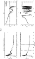
Fig. 4 die Einzelfunktionen eines Feedback-Systems mit h(n) (links oben), t(n) (links unten) und durch Dekonvolution erhaltene und approximierte Komplementärfilter - Impulsantwort (rechts oben), rechts unten: das Ergebnis der Faltung von Sekundärstrecke und approximiertem Komplementärfilter - Impulsantwort zur Kontrolle der erfolgreichen Synthetisierung der Zielfunktion.
- the
1 the graph of an approximation of an impulse response (complementary function) calculated according to the invention, from measured transmission paths and target function, using the Prony method, - the
2 an example of an IIR filter of 48kHz converted to 384kHz. The left column shows the original, the right the higher sampling rate version. The poles and zeros in the complex plane are shown above, magnitude (dashed) and phase response (solid) below - the
3 the result of the sampling rate adaptation of the impulse response using the example of the complementary filter function approximated with biquadratic filters (IIR) and - the
4 the individual functions of a feedback system with h ( n ) (top left), t ( n ) (bottom left) and complementary filters obtained and approximated by deconvolution - impulse response (top right), bottom right: the result of the convolution of the secondary path and the approximated complementary filter - Impulse response to control the successful synthesis of the target function.
Ein Beispiel für das erfindungsgemäße Verfahren bzw. das dabei verwendete Optimierungsverfahren (Methode) wird im Folgenden beschrieben:
Die hier erfindungsgemäße Methode verwendet IIR-Filter, da diese deutlich weniger Rechenleistung und Speicher als FIR-Filter bei gleichem Ergebnis bedürfen. Zusätzlich erlauben manche IC's ausschließlich IIR-Filter, sodass diese Methode universell einsetzbar ist. Es kann sich hierbei um ein Feedforward-, ein Feedback- oder ein Hybrid-System handeln. Ein Messsystem ermittelt die Impulsantworten der Übertragungsstrecken (Feedforward und Feedback). Dies kann mit allen üblichen Methoden erfolgen, etwa durch Anregung mittels Chirps oder Rauschen ist aber nicht auf diese beschränkt. Zu den ermittelten Impulsantworten der passiven Strecken müssen noch die bekannten Charakteristiken der Mikrophone und des Treibers, die ja vorliegen, hinzugefügt werden (mittels Konvolution). Somit ist die Impulsantwort der Feedforward-Strecke gegeben über: ![]()
The method according to the invention uses IIR filters since these require significantly less computing power and memory than FIR filters with the same result. In addition, some ICs only allow IIR filters, so this method can be used universally. This can be a feedforward, feedback or hybrid system. A measuring system determines the impulse responses of the transmission paths (feedforward and feedback). This can be done using all the usual methods, such as excitation using chirps or noise, but is not limited to these. The known characteristics of the microphones and the driver, which are already available, must be added (by means of convolution) to the determined impulse responses of the passive sections. Thus the impulse response of the feedforward path is given by:![]()
Wobei x(n) der Übertragungsstrecke des Lautsprechers des ANC-Kopfhörers zum Auslöschungspunkt des Feedforward ANC Systems (Kupplermikrofon, Kunstkopfmikrofon, realer Kopf mit Sondenmikrofon, o.Ä.) und m(n) der Übertragungsstrecke zwischen externem Lautsprecher (Noise Source) zum Feedforwardmikrofon entsprechen. Die Zielfunktion p(n) entspricht bei einem Feedforward-System der passiven Übertragungsstrecke zum Auslöschungspunkt. Aus den vorliegenden drei Strecken x(n), m(n) und p(n) kann also analog zum Feedback-System die angestrebte Komplementärfunktion f(n) durch Dekonvolution errechnet und anschließend nach dem erfindungsgemäßen Verfahren approximiert werden. Der Auslöschungspunkt beschreibt, wie im Stand der Technik üblich, den Punkt, an dem die durch das ANC-System erzeugte Gegenwelle die von außen in den Kopfhörer eindringende Schallwelle auslöscht.Where x(n) is the transmission path from the loudspeaker of the ANC headphones to the extinction point of the feedforward ANC system (coupler microphone, artificial head microphone, real head with probe microphone, or similar) and m(n) is the transmission path between the external loudspeaker (noise source) and the feedforward microphone correspond to. In a feedforward system, the objective function p ( n ) corresponds to the passive transmission path to the extinction point. From the present three For distances x ( n ), m ( n ) and p ( n ), the desired complementary function f ( n ) can be calculated analogously to the feedback system by deconvolution and then approximated using the method according to the invention. As is customary in the prior art, the cancellation point describes the point at which the counter wave generated by the ANC system cancels out the sound wave penetrating the headphones from the outside.
Die Feedback-Strecke wird ermittelt, indem eine Ziel-Impulsantwort t(n) durch Dekonvolution erreicht wird. ![]()
![]()
Die gemessene reale Impulsantwort h(n) die auch als Sekundärstrecke (entsprechend der Übertragungsstrecke zwischen ANC-Kopfhörer, Lautsprecher und Feedbackmikrofon) bezeichnet wird, gefaltet mit der errechneten Impulsantwort i(n) ergibt die Zielfunktion t(n). Somit sind die Impulsantworten für Feedforward und Feedback gegeben. Die Einzelfunktionen sowie die resultierende bereits approximierte Komplementärfilter-Impulsantwort sind in
Eine gegebene Impulsantwort kann als FIR-Filter der Länge der Impulsantwort betrachtet werden, wobei die Werte der einzelnen Samples als Filterkoeffizienten fungieren. Die Übertragungsfunktion hat somit die Form 
Ein IIR-Filter hingegen hat die Form 
Ein gegebener integrierter Schaltkreis hat aufgrund von Limitationen der Hardware nicht notwendigerweise die Möglichkeit ein FIR-Filter für ANC zu nutzen (solche Filter benötigt zu viele Taps). Mit einem IIR-Filter ist es hingegen schon möglich, da die rückgekoppelte Struktur weniger Taps benötigt. Daher ist es vorteilhaft die gegebene Impulsantwort durch ein IIR-Polynom zu approximieren.A given integrated circuit does not necessarily have the ability to use an FIR filter for ANC due to hardware limitations (such filters require too many taps). With an IIR filter, however, it is already possible, since the feedback structure requires fewer taps. It is therefore advantageous to approximate the given impulse response using an IIR polynomial.
Es gibt hierzu verschiedene Möglichkeiten: In einer Ausführungsform wird die Prony-Methode, in 
Durch die Approximation besitzt die ermittelte Transferfunktion mehr Koeffizienten als benötigt: ANC-Filter werden üblicherweise bis 2kHz definiert, da oberhalb eine gute passive Dämpfung erwartet werden kann. Optional kann die Ordnung der Transferfunktion reduziert werden.Due to the approximation, the determined transfer function has more coefficients than required: ANC filters are usually defined up to 2kHz, since good passive damping can be expected above this. Optionally, the order of the transfer function can be reduced.
Impulsantworten werden im Regelfall bei einer geringeren Abtastrate als im ANC-System verwendet aufgezeichnet. Üblich sind 44.1 oder 48kHz, während ein ANC-System eher 192 oder 384kHz getaktet ist. Das ermittelte IIR-Filter muss somit von z.B. 48kHz auf 384kHz skaliert werden, wobei der Frequenzgang absolut gesehen (in Hz) gleich bleiben soll (in einem relevanten Bereich).Impulse responses are typically recorded at a lower sample rate than used in the ANC system. 44.1 or 48kHz are common, while an ANC system is more likely to be clocked at 192 or 384kHz. The determined IIR filter must therefore be scaled from e.g. 48kHz to 384kHz, whereby the frequency response in absolute terms (in Hz) should remain the same (in a relevant range).
Die Skalierung eines IIR-Filters ist nicht offensichtlich, da sich die Transferfunktion ändern muss. Die hier vorgeschlagene Methode nutzt Pole und Nullstellen derThe scaling of an IIR filter is not obvious because the transfer function has to change. The method proposed here uses poles and zeros of the
Transferfunktion H(z). Der Einheitskreis auf der z-Ebene bildet den Frequenzgang ab (welcher auch über die Fourier Transformation ermittelt werden kann), da dort ![]()
![]()
An der (kartesischen) Koordinate 1 + 0j ist der DC-Anteil (0Hz) zu finden, während an -1 + 0j die halbe Abtastfrequenz zu finden ist (Nyquist-Frequenz). Für 48kHz ist die Nyquist Frequenz 24kHz. In Radiant handelt es sich um π, also den halben Einheitskreis. Für die höhere Abtastrate (384kHz) ist π gleich 192kHz. Das bedeutet im selben Bereich in Radiant befindet sich mehr Bandbreite (in Hz).The DC component (0Hz) can be found at the (Cartesian) coordinate 1 + 0j, while half the sampling frequency can be found at -1 + 0j (Nyquist frequency). For 48kHz, the Nyquist frequency is 24kHz. In radians it is π, which is half the unit circle. For the higher sampling rate (384kHz), π equals 192kHz. That means there is more bandwidth (in Hz) in the same range in radians.
Wird eine Gerade vom Ursprungspunkt (0 + 0j) durch einen Pol (oder eine Nullstelle) bis zu Einheitskreis gezogen ist zunächst deren Winkel (bezogen auf die Abszisse) für die niedrige Abtastrate ersichtlich. Der Punkt am Einheitskreis entspricht einer Frequenz f in Hz. ![]()
![]()
Der Punkt am Einheitskreis in Hz kann für die erhöhte Abtastrate in korrespondierenden Radianten umgerechnet werden. ![]()
![]()
Somit ist der Winkel bekannt um welchen die Pole und Nullstellen gedreht werden müssen um die Transferfunktion für die höhere Abtastrate zu skalieren. Zusätzlich müssen die Dämpfungsfaktoren angepasst werden. Die Linien konstanter Dämpfung der s-Ebene werden durch entsprechende Abbildung (bilineare Transformation, Impuls Invarianz, o.ä.) zu spiralförmigen Wurzel-Ortskurve auf der z-Ebene. Vom ursprünglichen Punkt eines Pols oder einer Nullstelle muss die Orts-Wurzel-Funktion zum DC-Punkt ermittelt werden. Die neue Position eines Pols/ Nullstelle ist an der Intersektion zwischen Orts-Wurzel-Funktion und des neuen Winkels für die höhere Abtastrate. Das Ergebnis dieser Anpassung ist in
Sonderregelungen des Vorgehens sind nötig für Pole/ Nullstellen welche an der Nyquist-Frequenz für die niedrige Abtastrate liegen: Da diese für die höhere Abtastrate wandert (von π zu < π) müssen diese Pole/Nullstellen mitwandern und entlang der Abszisse gespiegelt werden um ein reellwertiges Filter zu erhalten. In Zuge dieses Vorgangs können mehr Nullstellen als Pole entstehen, was zu einer nicht wohldefinierten Übertragungsfunktion führt. Es sind Pole nahe des Ursprungspunkts hinzuzufügen, so dass deren Einfluss gering ist aber die Übertragungsfunktion wohldefiniert wird. Es ist bekannt, dass ein Polynom mit mehr Koeffizienten im Zähler als im Nenner nicht wohldefiniert ist, da es anti-kausal wäre.Special regulations of the procedure are necessary for poles/zeros which are at the Nyquist frequency for the low sampling rate: Since this moves for the higher sampling rate (from π to < π), these poles/zeros must also move and be mirrored along the abscissa by a real value get filters. This process can result in more zeros than poles, resulting in an ill-defined transfer function. Add poles close to the origin point so that their influence is small but the transfer function becomes well defined. It is known that a polynomial with more coefficients in the numerator than in the denominator is not well defined since it would be anti-causal.
Nach skalieren der Übertragungsfunktion, entsprechend der
Die so gewonnenen Koeffizienten für biquadratische, somit rekursive, Filter können in eine Differenzengleichung umgewandelt und in einem passenden integrierten Schaltkreis verwendet werden. Da die meisten ANC Ics in Ihrer Programmieroberfläche/Entwicklungsumgebung die Möglichkeit haben, Filterkoeffizienten i.d.R. IIR manchmal auch FIR direkt einzugeben, ist dies problemlos durchführbar.The coefficients thus obtained for biquadratic, thus recursive, filters can be converted into a difference equation and used in a suitable integrated circuit. Since most ANC Ics in your programming interface/development environment have the option of entering filter coefficients usually IIR sometimes also FIR directly, this can be carried out without any problems.
Dabei wird beispielsweise im Signalprozessor eines Feedback ANC Systems das Feedback Filter mit den Koeffizienten, der nach obiger Beschreibung approximierten, errechneten Komplementärfunktion, programmiert. Diese Programmierung wird in der Regel über die Entwicklungsumgebung der jeweiligen Signalprozessoren (ANC Ics) oder durch einspielen einer mit den Koeffizienten versehenen Firmware über die bereits erläuterten Methoden bewerkstelligt.In this case, for example, the feedback filter is programmed in the signal processor of a feedback ANC system with the coefficients of the calculated complementary function approximated according to the above description. This programming is usually accomplished via the development environment of the respective signal processors (ANC Ics) or by importing firmware provided with the coefficients using the methods already explained.
Die Erfindung kann verschiedentlich abgewandelt und verändert werden, so kann das Messmittel neben den genannten Möglichkeiten eines Kunstkopfes, etc. jede andere Anordnung von Mikrofonen haben bzw. daraus bestehen, solange nur die benötigten, dem Fachmann in Kenntnis der Erfindung geläufigen, Daten erfasst werden.The invention can be modified and changed in various ways, so the measuring device can have or consist of any other arrangement of microphones in addition to the possibilities mentioned of an artificial head, etc., as long as only the required data are recorded that are familiar to the person skilled in the art with knowledge of the invention.
Ob zu Beginn des Verfahrens im Signalprozessor ein beliebiges oder ein aufgrund der Erfahrung schon in etwa angepasstes Filter konfiguriert ist, spielt letztlich keine Rolle, da ein nochmaliges Durchlaufen des Verfahrens vom Schritt b) an, eventuell mit weiteren Wiederholungen, zu einem raschen Erreichen des optimal erreichbaren Zustandes führt.Whether any filter is configured in the signal processor at the beginning of the method or a filter that has already been roughly adapted based on experience is ultimately irrelevant, since running through the method again from step b), possibly with further repetitions, will quickly achieve the optimum achievable state.
Da sich ANC Kopfhörer während Ihres Lebenszyklus verändern und sich dadurch ihre relevanten Übertragungsstrecken ändern können, kann eine Neukalibrierung sinnvoll sein. Die Aussparung von a) aus dieser Verfahrenswiederholung kommt daher, dass die Wiederholung auch unmittelbar nach der Erstanpassung erfolgen kann, sich die Kopfhörer daher noch auf dem Messkopf befinden.Since ANC headphones change during their life cycle and their relevant transmission paths can change as a result, recalibration can make sense. The omission of a) from this repetition of the procedure is due to the fact that the repetition can also take place immediately after the first fitting, and the headphones are therefore still on the measuring head.
Dies ist insbesondere bei der Endanpassung einer ganzen Serie von Kopfhörern spürbar, bei denen von einer Anfangskonfiguration ausgegangen werden kann, die beispielsweise durch den ersten erfindungsgemäß konfigurierten Kopfhörer erreicht ist.This is noticeable in particular in the final fitting of a whole series of headphones, in which an initial configuration can be assumed, which is achieved, for example, by the first headphones configured according to the invention.
Auch Adjustierungen von bereits länger benutzten Kopfhörern sind problemlos möglich.Adjustments to headphones that have been in use for a long time are also possible without any problems.
Ausgestaltungen der Erfindung sehen beispielsweise vor, dass im Schritt b) die Messung der Übertragungsstrecken digital mit der Abtastrate des Messsystems erfolgt, dass der ANC-Kopfhörer eine, vom digitalen Signalprozessor gegebene, Taktrate aufweist, dass die Taktrate höher ist als die Abtastrate und dass die/der approximierte/n ANC Filter im Verhältnis der Abtastrate zur Taktrate skaliert werden, wobei der Frequenzgang der/des approximierten Komplementärfilter/s absolut, in Hertz, betrachtet gleich bleibt. Das skalieren bereits approximierter ANC-Filter, entsprechend dem Verhältnis zwischen Taktrate des arbeitenden Signalprozessors im ANC-Hörer und Abtastrate des Messsystems bedeutet in anderen Worten, dass die Koeffizienten der IIR Filter-Funktion numerisch abgeändert werden, um mit der höheren Taktrate des Signalprozessors einen identen Frequenzgang zu erzeugen.Embodiments of the invention provide, for example, that in step b) the transmission links are measured digitally at the sampling rate of the measuring system, that the ANC headphones have a clock rate given by the digital signal processor, that the clock rate is higher than the sampling rate and that the /the approximated ANC filter(s) are scaled in the ratio of the sampling rate to the clock rate, whereby the frequency response of the approximated complementary filter(s) remains the same in absolute terms, in Hertz. In other words, the scaling of already approximated ANC filters according to the ratio between the clock rate of the working signal processor in the ANC listener and the sampling rate of the measuring system means that the coefficients of the IIR filter function are changed numerically in order to be identical with the higher clock rate of the signal processor generate frequency response.
Eine weitere Ausgestaltung sieht vor, dass im Schritt e) die Ordnung des/der approximierten Komplementärfilter/s höher ist/sind als der/die Signalprozessor(en) verarbeiten kann(können) und dass die Ordnung der/des approximierten Komplementärfilter/s passend für die Leistung des(der) Signalprozessors(en) reduziert wird.A further embodiment provides that in step e) the order of the approximated complementary filter(s) is/are higher than the signal processor(s) can process and that the order of the approximated complementary filter(s) is reduced appropriately for the performance of the signal processor(s).
Die Notwendigkeit zur Reduzierung der Ordnung ergibt sich aus dem Umstand, dass die Verarbeitung der Signalprozesse im Kopfhörer im Betrieb in Echtzeit erfolgen muss, da ANC nur für Echtzeitanwendungen sinnvoll ist. Digitale Signalprozessoren (DSP) verfügen über der Fachperson bekannte hardwaregebundene Eigenschaften, die Einschränkungen darstellen, welche bei Ihrer Benutzung beachtet werden müssen (z.B. Rechenoperationen/Zyklus, dem Prozessor immanente Taktraten, Energiebedarf, usw.). Daraus ergeben sich unzählige Gründe oder Einschränkungen warum Signalverarbeitungsprozesse (z.B. Filter) nicht in Echtzeit durchgeführt werden könnten. Die Aufzählung ist daher nicht als abschließend anzusehen. Die Auslastung der Signalprozessoren kann selbstverständlich neben der reinen Erzeugung eines ANC-Signals auch von anderen Faktoren, wie etwa der Verarbeitung des abzugebenden Audiosignals (etwa Musik), oder Bluetoothstreaming abhängen. Dabei handelt es sich jedoch um keinen zwingenden Umstand. Es wäre beispielsweise möglich mehrere Signalprozessoren in einem Kopfhörer zu verbauen, wobei jeder eine eigene Aufgaben übernimmt. Der Nachteil daran liegt auf der Hand und findet sich in höheren Kosten und einem größeren Verbrauch an Bauraum und/oder Energie. Da Kopfhörer traditionell mit einem begrenzten Platzangebot in ihrem Gehäuse auskommen müssen ist es vorteilhaft, aber nicht zwingend nötig, einem Signalprozessor mehrere Aufgaben zu übertragen. Aufgrund dieser Möglichkeit der Anpassung der Systemressourcen auf Basis der Zuteilung mehrerer Aufgaben an einen Signalprozessor kann es daher nötig werden die Ordnung des/der approximierten Komplementärfilter/s an den/die Signalprozessor(en) anzupassen.The need to reduce the order results from the fact that the signal processes in the headphones must be processed in real time during operation, since ANC only makes sense for real-time applications. Digital signal processors (DSP) have hardware-related properties known to those skilled in the art that represent restrictions that must be taken into account when they are used (e.g. arithmetic operations/cycle, clock rates inherent in the processor, energy requirements, etc.). This results in countless reasons or limitations why signal processing processes (e.g. filters) could not be carried out in real time. The list is therefore not to be regarded as conclusive. The utilization of the signal processors can of course depend not only on the pure generation of an ANC signal but also on other factors, such as the processing of the audio signal to be emitted (e.g. music) or Bluetooth streaming. However, this is not a compelling circumstance. For example, it would be possible to install several signal processors in one headphone, with each one taking on its own tasks. The disadvantage of this is obvious and can be found in the higher costs and greater consumption of installation space and/or energy. Since headphones traditionally have to make do with limited space in their housing, it is advantageous, but not absolutely necessary, to assign several tasks to a signal processor. Due to this possibility of adapting the system resources on the basis of the allocation of several tasks to a signal processor, it can therefore become necessary to adapt the order of the approximated complementary filter(s) to the signal processor(s).
Das IIR-Polynom bzw. die IIR-Kaskade 2ter Ordnung sind bereits eine Filterimplementierung. Die Ordnung wird reduziert falls der Signalprozessor nicht genügend Leistung besitzt um z.B. eine Kaskade aus 16 Filtern 2ter Ordnung auszuführen. Hier ist auf z.B. 8 Filter 2ter Ordnung zu reduzieren. Diese Reduktion muss so geschehen, dass die ANC-Performance nicht wesentlich beeinträchtigt wird. Dies ist weder trivial noch offensichtlich da bereits geringste Abweichungen vom Ideal zu starken negativen Effekten auf die Schallunterdrückung führt. Das wiederum ist jedem Fachmann auf dem Gebiet geläufig und wird vorausgesetzt.The IIR polynomial or the 2nd order IIR cascade is already a filter implementation. The order is reduced if the signal processor does not have enough power to execute a cascade of 16 second-order filters, for example. Here, for example, 8 filters of the 2nd order are to be reduced. This reduction must be done in such a way that ANC performance is not significantly affected. This is neither trivial nor obvious given that there are already the slightest deviations from the ideal leads to strong negative effects on the sound suppression. This in turn is familiar to anyone skilled in the field and is assumed.
Da digitale Signalprozessoren für ANC Anwendungen in Echtzeit arbeiten müssen, um Schallunterdrückung überhaupt möglich zu machen arbeiten diese bei weit höheren Taktraten (gängig sind z.B. max.768kkHz, typisch 384kHz) als typische Akustik-Messysteme (typisch 48kHz). Routinemäßige Umrechnung von Filtern für eine höhere Abtastrate ist bei bekannten Entwurfsverfahren möglich und dem Fachmann bekannt. Hier jedoch liegt eine Filterkaskade vor, die nicht einer bekannten Entwurfsmethode folgt (wie im Text ausgeführt mittels Approximation der Impulsantwort über die Prony-Methode), daher ist die Skalierung der Filter nicht mehr offensichtlich durchführbar. Die Pol/Nullstellen Positionen der IIR Filterpolynome, welche basierend auf den z.B. mit 48kHz gesampelten Übertragungsstrecken errechnet werden, dürfen sich beim Upsampling in Ihrer Position bezüglich der natürlichen Frequenz des Filters nicht verschieben da ansonsten die Filtercharakteristik nicht mehr zur benötigen Komplementärfunktion passt. Wohl aber müssen die Pole und Nullstellen auf der z-Ebene passend zur höheren Abtastrate des ANC-Systems abgeändert werden; so dass die Charakteristik der Filterkaskade bezüglich ihrer natürlichen Frequenz erhalten bleibt. Dabei treten unterschiedliche Problemstellungen auf: Behandlung von Sonderfällen wie Pole/Nullstellen auf der reellen Achse (0 bzw. Pi) welche bei 0 rad/s ebenso verschoben werden müssen um die Charakteristik beizubehalten. Desweitern bei Pi rad/s: Hier werden die Pole/Nullstellen von der Achse wegbewegt, müssen gespiegelt werden um ein reellwertiges Filter beizubehalten. All dies hat Einfluss auf Magnituden- und Phasengang der Filterkaskade und muss entsprechend kompensiert werden. Dieses Taktraten Anpassung ist aus diesem Grund maßgeblich für die Qualität des ANCs.Since digital signal processors for ANC applications have to work in real time in order to make sound suppression possible at all, they work at much higher clock rates (e.g. max. 768kHz, typically 384kHz) than typical acoustic measuring systems (typically 48kHz). Routine conversion of filters for a higher sampling rate is possible with known design methods and is known to a person skilled in the art. Here, however, there is a filter cascade that does not follow a known design method (as explained in the text by approximating the impulse response using the Prony method), so the scaling of the filters is no longer obviously feasible. The pole/zero positions of the IIR filter polynomials, which are calculated based on the transmission paths sampled at 48 kHz, for example, must not shift in their position with respect to the natural frequency of the filter during upsampling, otherwise the filter characteristics no longer match the required complementary function. However, the poles and zeros on the z-plane must be modified to match the higher sampling rate of the ANC system; so that the characteristic of the filter cascade with regard to its natural frequency is retained. Different problems arise: Treatment of special cases such as poles/zeros on the real axis (0 or Pi) which also have to be shifted at 0 rad/s in order to retain the characteristic. Furthermore at Pi rad/s: Here the poles/zeros are moved away from the axis, have to be mirrored in order to maintain a real-valued filter. All of this affects the magnitude and phase response of the filter cascade and must be compensated accordingly. For this reason, this clock rate adjustment is decisive for the quality of the ANC.
Die beschriebene Ermittlung, ob eine Reduzierung der Komplexität erforderlich ist wird nach der verfahrensgemäßen Messung von der bedienenden Fachperson oder einem entsprechenden Algorithmus getroffen. Diese Entscheidung muss nicht in Echtzeit geschehen, nachdem die Speicherung des Polynoms nicht zeitsensibel ist, da die Anpassung vor Verkauf des Kopfhörers geschieht. Auf diese Art kann gewährleistet werden, dass das ANC-System später seinerseits in Echtzeit agieren kann.The determination described as to whether a reduction in complexity is required is made by the operating specialist or a corresponding algorithm after the measurement according to the method. This decision does not have to be made in real time since the storage of the polynomial is not time sensitive since the adjustment is done before the headphone is sold. In this way it can be ensured that the ANC system can later act in real time.
Um die Erfindung mit Blick auf die Figuren noch einmal zu verdeutlichen wird hiermit festgehalten, die Erfindung betrifft ein Verfahren zur Kalibrierung bzw. Anpassung eines ANC-Kopfhörers der über zumindest einen Signalprozessor verfügt, auf dem zumindest ein ANC-Filter, insbesondere ein IIR-Filter, und dessen Parameter gespeichert sind, das folgende Schritte umfasst:
- a) Aufsetzen des Kopfhörers auf ein Messmittel, beispielsweise einen Kuppler, einen Kunstkopf mit Messmikrofonen, oder einen realen Kopf mit Sondenmikrofonen, enthaltend eine EDV mit einer Datenübertragung,
- b) Vermessen relevanter Übertragungsstrecken x(n), m(n) sowie p(n) für Feedforward und h(n) für Feedback, unter Anregen des ANC-Kreises eines Kopfhörers, beispielsweise durch Chirpen oder Rauschen,
dadurch gekennzeichnet, dass es weiters die Schritte - c) Definition zumindest einer Zielfunktion, -p(n) für Feedforward oder t(n) für Feedback, zur Kalkulation der Komplementärfunktion, f(n) für Feedforward oder i(n) für Feedback, zumindest eines Zweigs des ANC-Kreises (Feedforward oder Feedback) des Kopfhörers,
- d) Berechnen zumindest einer Impulsantwort der Komplementärfunktion/en, f(n) für Feedforward und/oder i(n) für Feedback, aus den Messungen der relevanten Übertragungsstrecken,
- e) Approximation der Parameter des/der ANC-Filter/s mittels Prony Methode, die zum Erreichen der Komplementärfunktion/en notwendig sind,
- f) Eingeben bzw. Aktivieren der berechneten Parameter im Signalprozessor umfasst.
- a) Putting the headphones on a measuring device, for example a coupler, an artificial head with measuring microphones, or a real head with probe microphones, containing an EDP with data transmission,
- b) Measurement of relevant transmission paths x (n), m ( n ) and p ( n ) for feedforward and h ( n ) for feedback, while stimulating the ANC circuit of a headphone, for example by chirping or noise,
characterized in that it further comprises steps - c) Definition of at least one objective function, - p ( n ) for feedforward or t ( n ) for feedback, for the calculation of the complementary function, f ( n ) for feedforward or i ( n ) for feedback, of at least one branch of the ANC circle (feedforward or feedback) of the headphones,
- d) calculating at least one impulse response of the complementary function/s, f ( n ) for feedforward and/or i ( n ) for feedback, from the measurements of the relevant transmission links,
- e) Approximation of the parameters of the ANC filter(s) using the Prony method, which are necessary to achieve the complementary function(s),
- f) entering or activating the calculated parameters in the signal processor.
Claims (5)
dadurch gekennzeichnet, dass es weiters die Schritte
characterized in that it further comprises steps
Applications Claiming Priority (1)
| Application Number | Priority Date | Filing Date | Title |
|---|---|---|---|
| EP20207549.5A EP4002871A1 (en) | 2020-11-13 | 2020-11-13 | Method for adapting anc headphones |
Publications (1)
| Publication Number | Publication Date |
|---|---|
| EP4002875A1 true EP4002875A1 (en) | 2022-05-25 |
Family
ID=73448933
Family Applications (2)
| Application Number | Title | Priority Date | Filing Date |
|---|---|---|---|
| EP20207549.5A Withdrawn EP4002871A1 (en) | 2020-11-13 | 2020-11-13 | Method for adapting anc headphones |
| EP21207962.8A Pending EP4002875A1 (en) | 2020-11-13 | 2021-11-12 | Method for adapting anc headphones |
Family Applications Before (1)
| Application Number | Title | Priority Date | Filing Date |
|---|---|---|---|
| EP20207549.5A Withdrawn EP4002871A1 (en) | 2020-11-13 | 2020-11-13 | Method for adapting anc headphones |
Country Status (2)
| Country | Link |
|---|---|
| US (1) | US11587543B2 (en) |
| EP (2) | EP4002871A1 (en) |
Citations (4)
| Publication number | Priority date | Publication date | Assignee | Title |
|---|---|---|---|---|
| WO2010049241A1 (en) | 2008-10-31 | 2010-05-06 | Austriamicrosystems Ag | Active noise control arrangement, active noise control headphone and calibration method |
| US20110222696A1 (en) | 2010-03-15 | 2011-09-15 | Nikhil Balachandran | Configurable electronic device reprogrammable to modify the device frequency response |
| US20190080682A1 (en) | 2016-03-17 | 2019-03-14 | Paul Darlington | Earphone Test System |
| CN111800694A (en) | 2020-06-30 | 2020-10-20 | 深圳市豪恩声学股份有限公司 | Filter design method and device of active noise reduction earphone and test equipment |
Family Cites Families (1)
| Publication number | Priority date | Publication date | Assignee | Title |
|---|---|---|---|---|
| US10034092B1 (en) * | 2016-09-22 | 2018-07-24 | Apple Inc. | Spatial headphone transparency |
-
2020
- 2020-11-13 EP EP20207549.5A patent/EP4002871A1/en not_active Withdrawn
-
2021
- 2021-11-12 US US17/454,782 patent/US11587543B2/en active Active
- 2021-11-12 EP EP21207962.8A patent/EP4002875A1/en active Pending
Patent Citations (5)
| Publication number | Priority date | Publication date | Assignee | Title |
|---|---|---|---|---|
| WO2010049241A1 (en) | 2008-10-31 | 2010-05-06 | Austriamicrosystems Ag | Active noise control arrangement, active noise control headphone and calibration method |
| US9779714B2 (en) | 2008-10-31 | 2017-10-03 | Ams Ag | Active noise control arrangement, active noise control headphone and calibration method |
| US20110222696A1 (en) | 2010-03-15 | 2011-09-15 | Nikhil Balachandran | Configurable electronic device reprogrammable to modify the device frequency response |
| US20190080682A1 (en) | 2016-03-17 | 2019-03-14 | Paul Darlington | Earphone Test System |
| CN111800694A (en) | 2020-06-30 | 2020-10-20 | 深圳市豪恩声学股份有限公司 | Filter design method and device of active noise reduction earphone and test equipment |
Non-Patent Citations (1)
| Title |
|---|
| SMITH JULIUS O.: "Filter Design by Minimizing the L2 Equation-Error Norm", INTRODUCTION TO DIGITAL FILTERS: WITH AUDIO APPLICATIONS, 2007, XP055901502, Retrieved from the Internet <URL:https://www.dsprelated.com/freebooks/filters/Filter_Design_Minimizing_L2.html> [retrieved on 20220315] * |
Also Published As
| Publication number | Publication date |
|---|---|
| US11587543B2 (en) | 2023-02-21 |
| US20220157289A1 (en) | 2022-05-19 |
| EP4002871A1 (en) | 2022-05-25 |
Similar Documents
| Publication | Publication Date | Title |
|---|---|---|
| DE102015101729B4 (en) | ECHO CANCELLATION METHOD AND ECHO CANCELLATION ARRANGEMENT FOR ELECTROACOUSTIC COMMUNICATION DEVICES | |
| DE112009005469B4 (en) | Loudspeaker protection device and method therefor | |
| DE69819090T2 (en) | compensating filter | |
| DE60303397T2 (en) | Digital audio compensation | |
| DE69933141T2 (en) | TONE PROCESSOR FOR ADAPTIVE DYNAMIC RANGE IMPROVEMENT | |
| DE112012006458B4 (en) | signal processing device | |
| DE10018666A1 (en) | Dynamic sound optimization in the interior of a motor vehicle or similar noisy environment, a monitoring signal is split into desired-signal and noise-signal components which are used for signal adjustment | |
| DE102010026884B4 (en) | Method for operating a hearing device with two-stage transformation | |
| JP2008278487A (en) | Sound tuning method | |
| EP3520441B1 (en) | Active suppression of the occlusion effect in hearing aids | |
| DE102009018812A1 (en) | Method for operating a hearing device and hearing device with a crossover network | |
| EP2981099B1 (en) | Method and device for suppressing feedback | |
| DE102019123971B4 (en) | ACTIVE NOISE COMPENSATION SYSTEM AND METHOD | |
| US20150036841A1 (en) | Filter with independently adjustable band gain and break point slopes and method of constructing same | |
| EP1728322A1 (en) | Circuit arrangement and signal processing device | |
| EP4002875A1 (en) | Method for adapting anc headphones | |
| DE102008024534A1 (en) | Hearing device with an equalization filter in the filter bank system | |
| DE102020200553B3 (en) | Method for matching the respective phase responses of a first microphone and a second microphone | |
| DE112019004139T5 (en) | SIGNAL PROCESSING DEVICE, SIGNAL PROCESSING METHOD AND PROGRAM | |
| EP1945000A1 (en) | Method for reducing interference and corresponding acoustic system | |
| DE102013207161A1 (en) | Method for use signal adaptation in binaural hearing aid systems | |
| EP2437521B1 (en) | Method for frequency compression with harmonic adjustment and corresponding device | |
| EP1309225B1 (en) | Method for determining the feedback threshold in a hearing aid | |
| DE10035673C1 (en) | Dynamic sound optimization in the interior of a motor vehicle or similar noisy environment, a monitoring signal is split into desired-signal and noise-signal components which are used for signal adjustment | |
| DE102012008557B4 (en) | Method for feedback suppression in electroacoustic systems |
Legal Events
| Date | Code | Title | Description |
|---|---|---|---|
| PUAI | Public reference made under article 153(3) epc to a published international application that has entered the european phase |
Free format text: ORIGINAL CODE: 0009012 |
|
| STAA | Information on the status of an ep patent application or granted ep patent |
Free format text: STATUS: THE APPLICATION HAS BEEN PUBLISHED |
|
| AK | Designated contracting states |
Kind code of ref document: A1 Designated state(s): AL AT BE BG CH CY CZ DE DK EE ES FI FR GB GR HR HU IE IS IT LI LT LU LV MC MK MT NL NO PL PT RO RS SE SI SK SM TR |
|
| STAA | Information on the status of an ep patent application or granted ep patent |
Free format text: STATUS: REQUEST FOR EXAMINATION WAS MADE |
|
| 17P | Request for examination filed |
Effective date: 20221117 |
|
| RBV | Designated contracting states (corrected) |
Designated state(s): AL AT BE BG CH CY CZ DE DK EE ES FI FR GB GR HR HU IE IS IT LI LT LU LV MC MK MT NL NO PL PT RO RS SE SI SK SM TR |