EP4002541A1 - Die-cutting lamination system and method - Google Patents
Die-cutting lamination system and method Download PDFInfo
- Publication number
- EP4002541A1 EP4002541A1 EP20839786.9A EP20839786A EP4002541A1 EP 4002541 A1 EP4002541 A1 EP 4002541A1 EP 20839786 A EP20839786 A EP 20839786A EP 4002541 A1 EP4002541 A1 EP 4002541A1
- Authority
- EP
- European Patent Office
- Prior art keywords
- separator
- lamination
- negative electrode
- positive
- cutting
- Prior art date
- Legal status (The legal status is an assumption and is not a legal conclusion. Google has not performed a legal analysis and makes no representation as to the accuracy of the status listed.)
- Pending
Links
- 238000003475 lamination Methods 0.000 title claims abstract description 313
- 238000005520 cutting process Methods 0.000 title claims abstract description 143
- 238000000034 method Methods 0.000 title claims abstract description 36
- 230000007246 mechanism Effects 0.000 claims abstract description 163
- 238000001514 detection method Methods 0.000 claims abstract description 35
- 230000002950 deficient Effects 0.000 claims abstract description 29
- 238000005096 rolling process Methods 0.000 claims abstract description 26
- 238000004804 winding Methods 0.000 claims abstract description 13
- 230000007547 defect Effects 0.000 claims abstract description 12
- 238000003825 pressing Methods 0.000 claims description 7
- 238000007599 discharging Methods 0.000 claims description 3
- 238000011144 upstream manufacturing Methods 0.000 claims description 3
- 239000010410 layer Substances 0.000 description 23
- 230000008569 process Effects 0.000 description 13
- 238000010586 diagram Methods 0.000 description 8
- 238000012546 transfer Methods 0.000 description 8
- 238000005516 engineering process Methods 0.000 description 4
- 238000004519 manufacturing process Methods 0.000 description 4
- 239000000463 material Substances 0.000 description 4
- 238000005265 energy consumption Methods 0.000 description 3
- 230000002349 favourable effect Effects 0.000 description 3
- HBBGRARXTFLTSG-UHFFFAOYSA-N Lithium ion Chemical compound [Li+] HBBGRARXTFLTSG-UHFFFAOYSA-N 0.000 description 2
- 230000000694 effects Effects 0.000 description 2
- 229910001416 lithium ion Inorganic materials 0.000 description 2
- 239000002356 single layer Substances 0.000 description 2
- 230000037303 wrinkles Effects 0.000 description 2
- 239000002390 adhesive tape Substances 0.000 description 1
- 238000011161 development Methods 0.000 description 1
- 238000011982 device technology Methods 0.000 description 1
- 230000007613 environmental effect Effects 0.000 description 1
- 238000003912 environmental pollution Methods 0.000 description 1
- 230000006872 improvement Effects 0.000 description 1
- 238000012423 maintenance Methods 0.000 description 1
- 238000012986 modification Methods 0.000 description 1
- 230000004048 modification Effects 0.000 description 1
- 238000006467 substitution reaction Methods 0.000 description 1
Images


Classifications
-
- H—ELECTRICITY
- H01—ELECTRIC ELEMENTS
- H01M—PROCESSES OR MEANS, e.g. BATTERIES, FOR THE DIRECT CONVERSION OF CHEMICAL ENERGY INTO ELECTRICAL ENERGY
- H01M10/00—Secondary cells; Manufacture thereof
- H01M10/04—Construction or manufacture in general
- H01M10/0463—Cells or batteries with horizontal or inclined electrodes
-
- H—ELECTRICITY
- H01—ELECTRIC ELEMENTS
- H01M—PROCESSES OR MEANS, e.g. BATTERIES, FOR THE DIRECT CONVERSION OF CHEMICAL ENERGY INTO ELECTRICAL ENERGY
- H01M10/00—Secondary cells; Manufacture thereof
- H01M10/05—Accumulators with non-aqueous electrolyte
- H01M10/058—Construction or manufacture
- H01M10/0583—Construction or manufacture of accumulators with folded construction elements except wound ones, i.e. folded positive or negative electrodes or separators, e.g. with "Z"-shaped electrodes or separators
-
- H—ELECTRICITY
- H01—ELECTRIC ELEMENTS
- H01M—PROCESSES OR MEANS, e.g. BATTERIES, FOR THE DIRECT CONVERSION OF CHEMICAL ENERGY INTO ELECTRICAL ENERGY
- H01M10/00—Secondary cells; Manufacture thereof
- H01M10/04—Construction or manufacture in general
- H01M10/0404—Machines for assembling batteries
-
- H—ELECTRICITY
- H01—ELECTRIC ELEMENTS
- H01M—PROCESSES OR MEANS, e.g. BATTERIES, FOR THE DIRECT CONVERSION OF CHEMICAL ENERGY INTO ELECTRICAL ENERGY
- H01M10/00—Secondary cells; Manufacture thereof
- H01M10/04—Construction or manufacture in general
- H01M10/0459—Cells or batteries with folded separator between plate-like electrodes
-
- H—ELECTRICITY
- H01—ELECTRIC ELEMENTS
- H01M—PROCESSES OR MEANS, e.g. BATTERIES, FOR THE DIRECT CONVERSION OF CHEMICAL ENERGY INTO ELECTRICAL ENERGY
- H01M50/00—Constructional details or processes of manufacture of the non-active parts of electrochemical cells other than fuel cells, e.g. hybrid cells
- H01M50/40—Separators; Membranes; Diaphragms; Spacing elements inside cells
- H01M50/46—Separators, membranes or diaphragms characterised by their combination with electrodes
-
- H—ELECTRICITY
- H01—ELECTRIC ELEMENTS
- H01M—PROCESSES OR MEANS, e.g. BATTERIES, FOR THE DIRECT CONVERSION OF CHEMICAL ENERGY INTO ELECTRICAL ENERGY
- H01M4/00—Electrodes
- H01M4/02—Electrodes composed of, or comprising, active material
- H01M4/04—Processes of manufacture in general
- H01M4/043—Processes of manufacture in general involving compressing or compaction
- H01M4/0435—Rolling or calendering
-
- Y—GENERAL TAGGING OF NEW TECHNOLOGICAL DEVELOPMENTS; GENERAL TAGGING OF CROSS-SECTIONAL TECHNOLOGIES SPANNING OVER SEVERAL SECTIONS OF THE IPC; TECHNICAL SUBJECTS COVERED BY FORMER USPC CROSS-REFERENCE ART COLLECTIONS [XRACs] AND DIGESTS
- Y02—TECHNOLOGIES OR APPLICATIONS FOR MITIGATION OR ADAPTATION AGAINST CLIMATE CHANGE
- Y02E—REDUCTION OF GREENHOUSE GAS [GHG] EMISSIONS, RELATED TO ENERGY GENERATION, TRANSMISSION OR DISTRIBUTION
- Y02E60/00—Enabling technologies; Technologies with a potential or indirect contribution to GHG emissions mitigation
- Y02E60/10—Energy storage using batteries
-
- Y—GENERAL TAGGING OF NEW TECHNOLOGICAL DEVELOPMENTS; GENERAL TAGGING OF CROSS-SECTIONAL TECHNOLOGIES SPANNING OVER SEVERAL SECTIONS OF THE IPC; TECHNICAL SUBJECTS COVERED BY FORMER USPC CROSS-REFERENCE ART COLLECTIONS [XRACs] AND DIGESTS
- Y02—TECHNOLOGIES OR APPLICATIONS FOR MITIGATION OR ADAPTATION AGAINST CLIMATE CHANGE
- Y02P—CLIMATE CHANGE MITIGATION TECHNOLOGIES IN THE PRODUCTION OR PROCESSING OF GOODS
- Y02P70/00—Climate change mitigation technologies in the production process for final industrial or consumer products
- Y02P70/50—Manufacturing or production processes characterised by the final manufactured product
Definitions
- the present disclosure relates to the field of battery technologies, and more particularly, to a die-cutting lamination system and a die-cutting lamination method.
- Lithium-ion device technology is a key technology for the development of electric vehicles.
- Square lamination technology is currently one of the most advanced lithium-ion battery manufacturing technologies, and the lamination speed directly determines the production capacity of the entire line and the cell manufacturing cost.
- the z-type lamination process is mostly adopted, the fastest lamination speed in the world in mass production is 0.6s/sheet, and this lamination speed is slow, resulting in a large number of device requirements, a large floor area, high purchase costs, and subsequent high maintenance costs and high energy consumption.
- a traditional lamination machine would include an air blower, a brush, a shaker, a double-sheet detector and other devices to prevent the double-sheet suction, and at present, no matter what method is used, the problem of double-sheet suction cannot be completely eliminated, and these devices greatly reduce the feeding speed of the manipulator; and the other reason is that the traditional lamination method is to laminate a negative electrode sheet first, then wrap a separator on the negative electrode sheet, then laminate a positive electrode sheet, and subsequently wrap a separator on the positive electrode sheet, a laminated unit of this lamination method is composed of a single electrode sheet or a single separator, and due to the limitation of the mechanical structure, the lamination speed cannot be substantially increased. Therefore, the lamination process is still to be further improved.
- the present disclosure aims to provide a die-cutting lamination system to improve the lamination efficiency.
- a die-cutting lamination system includes: unwinding mechanisms comprising a negative electrode unwinding mechanism, a separator unwinding mechanism, and a positive electrode unwinding mechanism, wherein the negative electrode unwinding mechanism and the positive electrode unwinding mechanism are arranged on an upper side and a lower side of the separator unwinding mechanism, and the negative electrode unwinding mechanism and/or the positive electrode unwinding mechanism is configured to operate at intervals relative to the separator unwinding mechanism; an electrode-winding cutting mechanism arranged downstream of the unwinding mechanisms and comprising a negative electrode cutting mechanism and a positive electrode cutting mechanism, wherein the negative electrode cutting mechanism is configured to cooperate with the negative electrode unwinding mechanism and cut negative electrode sheets, the positive electrode cutting mechanism is configured to cooperate with the positive electrode unwinding mechanism and cut positive electrode sheets, in such a manner that a laminated layer comprising a separator, the negative electrode sheets, and the positive electrode sheets is obtained, the negative electrode sheets and the positive electrode sheets being distributed on an upper side and a lower side
- the lamination apparatus comprises a clamping jaw, a first auxiliary roller, and a second auxiliary roller, and the clamping jaw and the first auxiliary roller are movable and are configured to cooperate with the second auxiliary roller to enable the positive-negative electrode sheet lamination units and the separator lamination units to be spread, aligned and alternately stacked.
- the negative electrode unwinding mechanism, the separator unwinding mechanism, and the positive electrode unwinding mechanism are distributed from top to bottom or from bottom to top among the unwinding mechanisms.
- the die-cutting lamination system further includes a plurality of tension rollers, the plurality of tension rollers being arranged between the unwinding mechanisms and the electrode-winding cutting mechanism and distributed on upper and/or lower sides of the negative electrode sheets, the separator, and the positive electrode sheets at intervals.
- a length of each of the cut positive electrode sheets is smaller than a length of each of the cut negative electrode sheets; and a horizontal distance between every two adjacent positive-negative electrode sheet lamination units is 1mm to 6mm greater than the length of each of the negative electrode sheets.
- the die-cutting lamination system further includes a discharger arranged downstream of the detection apparatus, and the discharger is configured to cooperate with the first separator cutting mechanism to discharge a defective lamination unit.
- the die-cutting lamination system disclosed by the present disclosure has the following advantages.
- the die-cutting apparatus and the lamination apparatus are integrated in the die-cutting lamination system, on the one hand, a feeding cartridge is omitted, and a limitation of feeding with the cartridge is broken through, on the other hand, the electrode sheets are adhered to the separator through preheating and roller pressing, the lamination feed is a roll material instead of a single sheet feed, and continuous feeding can be achieved, which can break through a limitation of the mechanical structure, increase the lamination speed, and reduce a system fault rate; (2) the number of lamination machines can be greatly reduced, the acquisition cost of the devices is reduced, the energy consumption of the device is reduced, and a theoretical lamination speed can reach 0.25s/sheet to 0.5s/sheet; (3) an edge shape of the separator after the separator is cut cannot be ensured and a risk of the separator wrinkling to expose the electrode sheets exists in the lamination process; instead, the separator between lamination units containing no defect is not cut during the lamination process using the die-cutting lamination system, but
- Another purpose of the present disclosure is to provide a die-cutting lamination method using the die-cutting lamination system described above, so as to improve a lamination efficiency.
- the technical solutions of the present disclosure are realized as follows.
- a die-cutting lamination method includes: (1) providing, by the unwinding mechanisms, electrode sheets and a separator, enabling the negative electrode cutting mechanism to cooperate with the negative electrode unwinding mechanism and cut negative electrode sheets, and enabling the positive electrode cutting mechanism to cooperate with the positive electrode unwinding mechanism and cut positive electrode sheets, to obtain a laminated layer comprising a separator, the negative electrode sheets, and the positive electrode sheets, the negative electrode sheets and the positive electrode sheets being distributed on an upper side and a lower side of the separator; (2) preheating, by the preheating apparatus, the separator, and the positive electrode sheets and the negative electrode sheets before and after the cutting, and roller-pressing, by the rolling apparatus, the laminated layer to respectively adhere the positive electrode sheets and the negative electrode sheets of the laminated layer to the separator to obtain a laminate comprising alternately distributed positive-negative electrode sheet lamination units and separator lamination units; (3) detecting, by the detection apparatus, whether the laminate has a defect, and cutting and discharging, by the first separator cutting mechanism
- a length of each positive electrode sheet in the electrode assembly is smaller than a length of each negative electrode sheet in the electrode assembly, and the length of each negative electrode sheet in the electrode assembly is 0.5mm to 3mm smaller than a length of each separator in the electrode assembly.
- the method further includes stacking, by the clamping jaw, the first auxiliary roller, and the second auxiliary roller in cooperation, lamination units to obtain the electrode assembly in which the positive-negative electrode sheet lamination units and the separator lamination units are spread, aligned, and alternately stacked.
- the method further includes: positioning the negative electrode sheet above the separator, positioning the positive electrode sheet below the separator, pre-stacking one negative electrode lamination unit, and then alternately stacking a plurality of separator lamination units and a plurality of positive-negative electrode sheet lamination units; or positioning the positive electrode sheet above the separator, positioning the negative electrode sheet below the separator, alternately pre-stacking a plurality of separator lamination units and a plurality of positive-negative electrode sheet lamination units, and then stacking one negative electrode lamination unit.
- the die-cutting lamination method disclosed by the present disclosure has the following advantages.
- the electrode sheet cutting and lamination are coupled together, on the one hand, a feeding cartridge is omitted, and a limitation of feeding with the cartridge is broken through, on the other hand, the electrode sheets are adhered to the separator through preheating and roller pressing to form the lamination units, the lamination feed is a roll material instead of a single sheet feed, and continuous feeding can be achieved, which can break through a limitation of the mechanical structure, increase the lamination speed, and reduce a system fault rate; (2) the electrode sheets and the separator are laminated synchronously, the lamination speed is fast, and a theoretical lamination speed can reach 0.25s/sheet to 0.5s/sheet; (3) a number of cuttings of the separator is very small, which greatly reduces a risk of the separator wrinkling to expose the electrode sheets; (4) compared with a manner that each lamination unit is cut off separately and then detected and laminated, there is no need to transfer lamination units during detection of the lamination units, and the process is simpler; (5) the lamination manner
- a die-cutting lamination system is provided.
- the system includes an unwinding mechanism 100, an electrode-winding cutting mechanism 200, a preheating and rolling device 300, a detection apparatus 400, a separator cutting mechanism 500, and a lamination apparatus 600.
- the unwinding mechanism 100 includes a negative electrode unwinding mechanism 110, a separator unwinding mechanism 120, and a positive electrode unwinding mechanism 130
- the negative electrode unwinding mechanism 110 and the positive electrode unwinding mechanism 130 are arranged on an upper side and a lower side of the separator unwinding mechanism 120
- the negative electrode unwinding mechanism 110 and/or the positive electrode unwinding mechanism 130 is configured to operate at intervals relative to the separator unwinding mechanism 120.
- the electrode-winding cutting mechanism 200 is arranged downstream of the unwinding mechanism 100, and the electrode-winding cutting mechanism 200 includes a negative electrode cutting mechanism 210 and a positive electrode cutting mechanism 220.
- the negative electrode cutting mechanism 210 is configured to cooperate with the negative electrode unwinding mechanism 110 and cut negative electrode sheets
- the positive electrode cutting mechanism 130 is configured to cooperate with the positive electrode unwinding mechanism 220 and cut positive electrode sheets, in such a manner that a laminated layer including a separator, the negative electrode sheets, and the positive electrode sheets is obtained, the negative electrode sheets and the positive electrode sheets being distributed on an upper side and a lower side of the separator.
- the laminated layer including the separator and the negative electrode sheets and the positive electrode sheets that are distributed on the upper side and the lower side of the separator includes two parts, one part includes three-layer structures in each of which one negative electrode sheet and one positive electrode sheet are distributed on the upper side and the lower side of the separator and centers of the negative electrode sheet, the positive electrode sheet, and the separator are aligned, and the other part includes single-layer separator structures containing no positive electrode sheet and no negative electrode sheet.
- the three-layer structures are roller-pressed by a rolling apparatus to form positive-negative electrode sheet lamination units A, and the single-layer separator structures form separator lamination units B.
- an unwinding speed of the positive electrode unwinding mechanism and an unwinding speed of the negative electrode unwinding mechanism and a cutting interval of the positive electrode cutting mechanism and a cutting interval of the negative electrode cutting mechanism can be adjusted comprehensively, so that a length of the positive electrode sheet that has been cut is smaller than a length of the cut negative electrode sheet, and a horizontal distance between every two adjacent positive-negative electrode sheet lamination units is 1mm to 6mm larger than the length of the cut negative electrode sheet, in such a manner that the length of the separator, the length of the negative electrode sheet, and the length of the positive electrode sheet decrease in order in the finally obtained electrode assembly.
- the length of the negative electrode sheet can be 0.5mm to 3 mm smaller than the length of the separator.
- a length difference d between each side of the positive electrode sheet and a corresponding side of the negative electrode sheet can be 0.5mm to 1.5mm, ensuring that the electrode assembly has high safety and stability. It should be noted that the length described in the present disclosure is defined in terms of a moving direction of the electrode sheets, and can also be understood as the length of a respective side.
- the die-cutting lamination system may further include a plurality of tension rollers 700, and the plurality of tension rollers 700 are arranged between the unwinding mechanism 100 and the electrode-winding cutting mechanism 200 and are distributed on upper and/or lower sides of the negative electrode sheet, the separator, and the positive electrode sheet at intervals, thereby facilitating unwinding and starting and stopping of the electrode sheets and the separator.
- the negative electrode unwinding mechanism 110, the separator unwinding mechanism 120, and the positive electrode unwinding mechanism 130 in the unwinding mechanism 100 may be distributed from top to bottom (as illustrated in FIG. 1 ) or from bottom to top (as illustrated in FIG. 2 ).
- the preheating and rolling device 300 includes a preheating apparatus (not individually shown) and a rolling apparatus (not individually shown) that are sequentially connected, the preheating apparatus is arranged between the unwinding mechanism 110 and the rolling apparatus, the rolling apparatus is arranged downstream of the electrode-winding cutting mechanism 200, and the rolling apparatus is configured to enable the positive electrode sheets and the negative electrode sheets of the laminated layer to be respectively adhered to the separator to obtain a laminate including alternately distributed positive-negative electrode sheet lamination units and separator lamination units.
- the preheating apparatus can preheat the separator, the positive electrode sheet, and the negative electrode sheet before the electrode sheets are cut, so that the preheating time can be longer, and an adhesion effect of the roller-pressed electrode sheets and separator can be further improved.
- the detection apparatus 400 is arranged downstream of the preheating and rolling device 300, and configured to detect whether the laminate has a defect.
- the detection apparatus 400 can detect a position, a size, a wrinkle, a tab wrinkle, a folded edge, an unfilled corner and the like of the electrode sheets/separator, so that defective lamination units can be discarded in time; further, when the lamination units are under detection with the detection apparatus, there is no need for the lamination units to be transferred, it is no longer necessary to separately and additionally provide a positioning platform and a group of manipulators, and the structure is simpler.
- the detection apparatus 400 may be a CCD detection mechanism.
- the separator cutting mechanism 500 includes a first separator cutting mechanism 510 and a second separator cutting mechanism 520.
- the first separator cutting mechanism 510 is arranged upstream of the second separator cutting mechanism 520, and configured to cut and discharge, based on a detection result of the detection apparatus, a defective positive-negative electrode sheet lamination unit/a defective separator lamination unit and a separator lamination unit/a positive-negative electrode sheet lamination unit adjacent to the defective positive-negative electrode sheet lamination unit/the defective separator lamination unit in pairs.
- the second separator cutting mechanism 520 is configured to perform separator cutting on a last qualified lamination unit based on a number of layers to be laminated.
- the positive-negative electrode sheet lamination unit and the separator lamination unit need to be discharged in pairs, for example, if one positive-negative electrode sheet lamination unit has a defect, one separator lamination unit needs to be discarded at the same time; in addition, the separator between lamination units having no defect is not cut off in the subsequent lamination process, and the separator is cut off by the second separator cutting mechanism only after the lamination is finished, so that the number of times for cutting the separator is very small, and a risk of the separator wrinkling to expose the electrode sheets in the lamination process is greatly reduced.
- the die-cutting lamination system may further include a discharger 800, and the discharger 800 may be arranged downstream of the detection apparatus 400 and configured to cooperate with the first separator cutting mechanism 510 to discharge a defective lamination unit based on the display of the detection apparatus 400.
- the discharger 800 may be an NG discharger.
- the lamination apparatus 600 is arranged downstream of the separator cutting mechanism 500 and configured to stack the positive-negative electrode sheet lamination units A and the separator lamination units B alternately, thereby obtaining an electrode assembly including a plurality of layers of positive electrode sheet and a plurality of layers of negative electrode sheet.
- the lamination apparatus 600 may include a clamping jaw 610, a first auxiliary roller 620, and a second auxiliary roller 630, the clamping jaw 610 and the first auxiliary roller 620 are movable and are configured to cooperate with the second auxiliary roller 630 in such a manner that the positive-negative electrode sheet lamination units and the separator lamination units are spread, aligned and alternately stacked.
- the clamping jaw clamps the laminate from upper and lower sides of the lamination units (as illustrated in FIG.
- the clamping jaw can clamp the laminate from an upper side and a lower side that are perpendicular to a moving direction of the electrode sheets), and the first auxiliary roller and the second auxiliary roller cooperate with the clamping jaw to realize the stacking of two adjacent lamination units, and assist in the alignment of the lamination units;
- the position of the second auxiliary roller is relatively fixed and can be finely adjusted, and the tension of the lamination units is controlled by adjusting the first auxiliary roller and the second auxiliary roller, so that the lamination units are alternately stacked and aligned;
- the lamination manner of the present disclosure using the cooperation of the clamping jaw with the auxiliary rollers is a horizontal lamination manner, which is not only more conducive to lamination alignment and but also allows a smaller space occupancy rate of the system in the vertical direction, compared with a vertical lamination manner;
- the clamping jaw is adopted to replace a negative pressure manipulator to realize the transfer of lamination units, which can effectively avoid a risk of dropping of a lower separator and/
- the lamination apparatus 600 includes two sets of the first auxiliary roller 620 and the second auxiliary roller 630.
- One set is in an operating state in which the auxiliary rollers cooperate with the clamping jaw to stack and align two adjacent lamination units, the other set is in a ready state for stacking and aligning a next pair of lamination units, and after the two adjacent lamination units are stacked and aligned, the auxiliary rollers in the operating state are withdrawn and enter the ready state.
- FIG. 4 FIG. 4
- FIG. 4 is a schematic diagram showing a start of lamination of one electrode assembly with the negative electrode sheet located above the separator and the positive electrode sheet located below the separator), the auxiliary rollers are in the ready state, the first auxiliary roller 620 is located at position 1, and the second auxiliary roller 630 is located at position 2; when the clamping jaw 610 clamps a lamination unit and transfers the lamination unit to the lamination position, the set of auxiliary rollers is put into operation, the first auxiliary roller 620 is transferred to position 3, the position of the second auxiliary roller is basically unchanged, and the second auxiliary roller is only finely adjusted at the original position to aid in aligning the lamination unit, and at this time, the other set of auxiliary rollers is let ready at position 1 and position 2.
- the negative electrode unwinding mechanism 110, the separator unwinding mechanism 120, and the positive electrode unwinding mechanism 130 in the unwinding mechanism 100 are distributed from top to bottom, the negative electrode sheet is positioned above the separator, the positive electrode sheet is positioned below the separator, one negative electrode lamination unit is pre-stacked, and then a plurality of separator lamination units B and a plurality of positive-negative electrode sheet lamination units A are stacked alternately; as illustrated in FIG.
- the positive electrode sheet is positioned above the separator, the negative electrode sheet is positioned below the separator, a plurality of separator lamination units and a plurality of positive-negative electrode sheet lamination units are pre-stacked alternately, and then one negative electrode lamination unit is stacked.
- the negative electrode lamination unit includes a layer of negative electrode sheet and a layer of separator.
- the unwinding of the positive electrode unwinding mechanism is suspended, and only the negative electrode unwinding mechanism and the separator unwinding mechanism perform unwinding, until a first cutting operation of the negative electrode cutting mechanism is completed and a negative electrode lamination unit including a separator and a negative electrode sheet positioned on the separator is obtained; subsequently, the unwinding of the negative electrode unwinding mechanism is suspended, and only the separator unwinding mechanism continues the unwinding operation to form a separator lamination unit B; then the unwinding of the negative electrode unwinding mechanism and the unwinding of the negative electrode unwinding mechanism are started or suspended synchronously to obtain a laminated layer containing alternately staked positive-negative electrode sheet lamination units A and separator lamination units B by adjusting the unwinding speeds of the unwinding
- a laminated layer containing alternately stacked separator lamination units B and positive-negative electrode sheet lamination units A is formed first, i.e., the separator lamination units B and the positive-negative electrode sheet lamination units A are sequentially and alternately stacked, and the last lamination unit is a negative electrode lamination unit containing no positive electrode sheet.
- the die-cutting lamination system of the present disclosure has the following advantages: (1) according to the present disclosure, the die-cutting apparatus and the lamination apparatus are integrated in the die-cutting lamination system, on the one hand, a feeding cartridge is omitted, and a limitation of feeding with the cartridge is broken through, on the other hand, the electrode sheets are adhered to the separator through preheating and roller pressing, the lamination feed is a roll material instead of a single sheet feed, and continuous feeding can be achieved, which can break through a limitation of the mechanical structure, increase the lamination speed, and reduce a system fault rate; (2) the number of lamination machines can be greatly reduced, the acquisition cost of the devices is reduced, the energy consumption of the device is reduced, and a theoretical lamination speed can reach 0.25s/sheet to 0.5s/sheet; (3) an edge shape of the separator after the separator is cut cannot be ensured and a risk of the separator wrinkling to expose the electrode sheets exists in the lamination process; instead, the separator between lamination units containing no
- the present disclosure provides a die-cutting lamination method using the die-cutting lamination system.
- the method includes: (1) providing, by the unwinding mechanisms, electrode sheets and a separator, enabling the negative electrode cutting mechanism to cooperate with the negative electrode unwinding mechanism and cut negative electrode sheets, and enabling the positive electrode cutting mechanism to cooperate with the positive electrode unwinding mechanism and cut positive electrode sheets, to obtain a laminated layer including the separator, the negative electrode sheets, and the positive electrode sheets, the negative electrode sheets and the positive electrode sheets being distributed on an upper side and a lower side of the separator; (2) preheating, by the preheating apparatus, the separator, and the positive electrode sheets and the negative electrode sheets before and after cutting, and roller pressing, by the rolling apparatus, the laminated layer to respectively adhere the positive electrode sheets and the negative electrode sheets of the laminated layer to the separator to obtain a laminate including alternately distributed positive-negative electrode sheet lamination units
- the lamination units may be stacked by the clamping jaw, the first auxiliary roller, and the second auxiliary roller in cooperation to obtain the electrode assembly in which positive-negative electrode sheet lamination units and separator sheet lamination units are spread, aligned, and alternately stacked.
- the lamination manner is a horizontal lamination manner, and compared with the vertical lamination manner, the horizontal lamination manner is more favorable for the alignment of the lamination and the system occupies smaller space in the vertical direction; further, according to the present disclosure, the clamping jaw is adopted to replace the negative pressure manipulator to realize the transfer of lamination units, which can effectively avoid a risk of dropping of a lower electrode sheet and/or a separator of a lamination unit when sucking an upper side of the lamination unit to transfer the lamination unit.
- a length of each positive electrode sheet in the finally obtained electrode assembly is smaller than a length of each negative electrode sheet in the finally obtained electrode assembly, for example, by 0.5mm to 3mm or 0.5mm to 1.5mm, and the length of each negative electrode sheet in the finally obtained electrode assembly may be 0.5mm to 3mm smaller than a length of each separator in the finally obtained electrode assembly. The risk of exposing the electrode sheets can thereby be avoided.
- one negative electrode lamination unit when the negative electrode sheet is positioned above the separator and the positive electrode sheet is positioned below the separator, one negative electrode lamination unit is pre-stacked, and then a plurality of separator lamination units and a plurality of positive-negative electrode sheet lamination units are stacked alternately; and when the positive electrode sheet is positioned above the separator and the negative electrode sheet is positioned below the separator, a plurality of separator lamination units and a plurality of positive-negative electrode sheet lamination units are alternately pre-stacked, and then one negative electrode sheet lamination unit is stacked.
- the die-cutting lamination method of the present disclosure has the following advantages.
- (1) the electrode sheet cutting and lamination are coupled together, on the one hand, a feeding cartridge is omitted, and a limitation of feeding with the cartridge is broken through, on the other hand, the electrode sheets are adhered to the separator through preheating and roller pressing to form the lamination units, the lamination feed is a roll material instead of a single sheet feed, and continuous feeding can be achieved, which can break through a limitation of the mechanical structure, increase the lamination speed, and reduce a system fault rate; (2) the electrode sheets and the separator are laminated synchronously, the lamination speed is fast, and a theoretical lamination speed can reach 0.25s/sheet to 0.5s/sheet; (3) a number of cuttings of the separator is very small, which greatly reduces a risk of the separator wrinkling to expose the electrode sheets; (4) compared with a manner that each lamination unit is cut off separately and then detected and laminated, there is no need to transfer lamination units
Landscapes
- Chemical & Material Sciences (AREA)
- Chemical Kinetics & Catalysis (AREA)
- Electrochemistry (AREA)
- General Chemical & Material Sciences (AREA)
- Engineering & Computer Science (AREA)
- Manufacturing & Machinery (AREA)
- Secondary Cells (AREA)
Abstract
Description
- The present application claims priority to
Chinese Patent Application No. 201910641926.1, filed on July 16, 2019 - The present disclosure relates to the field of battery technologies, and more particularly, to a die-cutting lamination system and a die-cutting lamination method.
- In the automotive industry environment that uses traditional energy as a power supply, environmental pollution issues have aroused people's attention to environmental protection and resource utilization. Actively developing new energy vehicles and realizing the electrification of the automobile industry are strategic measures to achieve the goal of "overtaking on a bend" over the foreign automobile industry. Lithium-ion device technology is a key technology for the development of electric vehicles. Square lamination technology is currently one of the most advanced lithium-ion battery manufacturing technologies, and the lamination speed directly determines the production capacity of the entire line and the cell manufacturing cost.
- At present, the z-type lamination process is mostly adopted, the fastest lamination speed in the world in mass production is 0.6s/sheet, and this lamination speed is slow, resulting in a large number of device requirements, a large floor area, high purchase costs, and subsequent high maintenance costs and high energy consumption. There are two main reasons for the slow lamination speed: one reason is that the lamination adopts cartridge type feeding, there will be a double-sheet suction phenomenon during the feeding process, therefore, a traditional lamination machine would include an air blower, a brush, a shaker, a double-sheet detector and other devices to prevent the double-sheet suction, and at present, no matter what method is used, the problem of double-sheet suction cannot be completely eliminated, and these devices greatly reduce the feeding speed of the manipulator; and the other reason is that the traditional lamination method is to laminate a negative electrode sheet first, then wrap a separator on the negative electrode sheet, then laminate a positive electrode sheet, and subsequently wrap a separator on the positive electrode sheet, a laminated unit of this lamination method is composed of a single electrode sheet or a single separator, and due to the limitation of the mechanical structure, the lamination speed cannot be substantially increased. Therefore, the lamination process is still to be further improved.
- In view of this, the present disclosure aims to provide a die-cutting lamination system to improve the lamination efficiency.
- In order to achieve the purpose, the technical solutions of the present disclosure are realized as follows.
- A die-cutting lamination system is proposed, and the system includes: unwinding mechanisms comprising a negative electrode unwinding mechanism, a separator unwinding mechanism, and a positive electrode unwinding mechanism, wherein the negative electrode unwinding mechanism and the positive electrode unwinding mechanism are arranged on an upper side and a lower side of the separator unwinding mechanism, and the negative electrode unwinding mechanism and/or the positive electrode unwinding mechanism is configured to operate at intervals relative to the separator unwinding mechanism; an electrode-winding cutting mechanism arranged downstream of the unwinding mechanisms and comprising a negative electrode cutting mechanism and a positive electrode cutting mechanism, wherein the negative electrode cutting mechanism is configured to cooperate with the negative electrode unwinding mechanism and cut negative electrode sheets, the positive electrode cutting mechanism is configured to cooperate with the positive electrode unwinding mechanism and cut positive electrode sheets, in such a manner that a laminated layer comprising a separator, the negative electrode sheets, and the positive electrode sheets is obtained, the negative electrode sheets and the positive electrode sheets being distributed on an upper side and a lower side of the separator; a preheating and rolling device comprising a preheating apparatus and a rolling apparatus which are sequentially connected, wherein the preheating apparatus is arranged between the unwinding mechanisms and the rolling apparatus, the rolling apparatus is arranged downstream of the electrode-winding cutting mechanism, and the rolling apparatus is configured to enable the positive electrode sheets and the negative electrode sheets of the laminated layer to be respectively adhered to the separator to obtain a laminate comprising alternately distributed positive-negative electrode sheet lamination units and separator lamination units; a detection apparatus arranged downstream of the preheating and rolling device and configured to detect whether the laminate has a defect; separator cutting mechanisms comprising a first separator cutting mechanism and a second separator cutting mechanism, wherein the first separator cutting mechanism is arranged upstream of the second separator cutting mechanism, and configured to cut and discharge, based on a detection result of the detection apparatus, a defective positive-negative electrode sheet lamination unit/a defective separator lamination unit and a separator lamination unit/a positive-negative electrode sheet lamination unit adjacent to the defective positive-negative electrode sheet lamination unit/the defective separator lamination unit in pairs, and the second separator cutting mechanism is configured to perform separator cutting on a last qualified lamination unit based on a number of layers to be laminated; and a lamination apparatus arranged downstream of the separator cutting mechanisms and configured to stack the positive-negative electrode sheet lamination units and the separator lamination units alternately.
- Further, the lamination apparatus comprises a clamping jaw, a first auxiliary roller, and a second auxiliary roller, and the clamping jaw and the first auxiliary roller are movable and are configured to cooperate with the second auxiliary roller to enable the positive-negative electrode sheet lamination units and the separator lamination units to be spread, aligned and alternately stacked.
- Further, the negative electrode unwinding mechanism, the separator unwinding mechanism, and the positive electrode unwinding mechanism are distributed from top to bottom or from bottom to top among the unwinding mechanisms.
- Further, the die-cutting lamination system further includes a plurality of tension rollers, the plurality of tension rollers being arranged between the unwinding mechanisms and the electrode-winding cutting mechanism and distributed on upper and/or lower sides of the negative electrode sheets, the separator, and the positive electrode sheets at intervals.
- Further, a length of each of the cut positive electrode sheets is smaller than a length of each of the cut negative electrode sheets; and a horizontal distance between every two adjacent positive-negative electrode sheet lamination units is 1mm to 6mm greater than the length of each of the negative electrode sheets.
- Further, the die-cutting lamination system further includes a discharger arranged downstream of the detection apparatus, and the discharger is configured to cooperate with the first separator cutting mechanism to discharge a defective lamination unit.
- Compared with the related art, the die-cutting lamination system disclosed by the present disclosure has the following advantages.
- (1) According to the present disclosure, the die-cutting apparatus and the lamination apparatus are integrated in the die-cutting lamination system, on the one hand, a feeding cartridge is omitted, and a limitation of feeding with the cartridge is broken through, on the other hand, the electrode sheets are adhered to the separator through preheating and roller pressing, the lamination feed is a roll material instead of a single sheet feed, and continuous feeding can be achieved, which can break through a limitation of the mechanical structure, increase the lamination speed, and reduce a system fault rate; (2) the number of lamination machines can be greatly reduced, the acquisition cost of the devices is reduced, the energy consumption of the device is reduced, and a theoretical lamination speed can reach 0.25s/sheet to 0.5s/sheet; (3) an edge shape of the separator after the separator is cut cannot be ensured and a risk of the separator wrinkling to expose the electrode sheets exists in the lamination process; instead, the separator between lamination units containing no defect is not cut during the lamination process using the die-cutting lamination system, but is cut only after the lamination process is finished, and a number of cuttings of the separator is very small, which greatly reduces the risk of the separator wrinkling to expose the electrode sheets; (4) if each lamination unit is cut off separately and then detected and laminated, the cut lamination units need to be transferred to a positioning platform and then transferred to a lamination platform after being detected by a detection apparatus, namely, an additional group of manipulators and an additional positioning platform need to be added; instead, when the die-cutting lamination system disclosed by the present disclosure is adopted to detect the lamination units, there is no need to separately provide an additional positioning platform or an additional group of manipulators, and the structure is simpler; (5) the lamination of the system can be conducted in a horizontal manner, thereby facilitating lamination alignment and reducing a space occupation of the system in the vertical direction.
- Another purpose of the present disclosure is to provide a die-cutting lamination method using the die-cutting lamination system described above, so as to improve a lamination efficiency. In order to achieve the purpose, the technical solutions of the present disclosure are realized as follows.
- A die-cutting lamination method is proposed, and the method includes: (1) providing, by the unwinding mechanisms, electrode sheets and a separator, enabling the negative electrode cutting mechanism to cooperate with the negative electrode unwinding mechanism and cut negative electrode sheets, and enabling the positive electrode cutting mechanism to cooperate with the positive electrode unwinding mechanism and cut positive electrode sheets, to obtain a laminated layer comprising a separator, the negative electrode sheets, and the positive electrode sheets, the negative electrode sheets and the positive electrode sheets being distributed on an upper side and a lower side of the separator; (2) preheating, by the preheating apparatus, the separator, and the positive electrode sheets and the negative electrode sheets before and after the cutting, and roller-pressing, by the rolling apparatus, the laminated layer to respectively adhere the positive electrode sheets and the negative electrode sheets of the laminated layer to the separator to obtain a laminate comprising alternately distributed positive-negative electrode sheet lamination units and separator lamination units; (3) detecting, by the detection apparatus, whether the laminate has a defect, and cutting and discharging, by the first separator cutting mechanism, based on a detection result of the detection apparatus, a defective positive-negative electrode sheet lamination unit/a defective separator lamination unit and a separator lamination unit/a positive-negative electrode sheet lamination unit adjacent to the defective positive-negative electrode sheet lamination unit/the defective separator lamination unit in pairs; and (4) alternately stacking, by the lamination apparatus, the positive-negative electrode sheet lamination units and the separator lamination units, and performing separator cutting, by the second separator cutting mechanism, on a last qualified lamination unit based on a number of layers to be laminated to obtain an electrode assembly.
- Further, a length of each positive electrode sheet in the electrode assembly is smaller than a length of each negative electrode sheet in the electrode assembly, and the length of each negative electrode sheet in the electrode assembly is 0.5mm to 3mm smaller than a length of each separator in the electrode assembly.
- Further, the method further includes stacking, by the clamping jaw, the first auxiliary roller, and the second auxiliary roller in cooperation, lamination units to obtain the electrode assembly in which the positive-negative electrode sheet lamination units and the separator lamination units are spread, aligned, and alternately stacked.
- Further, the method further includes: positioning the negative electrode sheet above the separator, positioning the positive electrode sheet below the separator, pre-stacking one negative electrode lamination unit, and then alternately stacking a plurality of separator lamination units and a plurality of positive-negative electrode sheet lamination units; or positioning the positive electrode sheet above the separator, positioning the negative electrode sheet below the separator, alternately pre-stacking a plurality of separator lamination units and a plurality of positive-negative electrode sheet lamination units, and then stacking one negative electrode lamination unit.
- Compared with the related art, the die-cutting lamination method disclosed by the present disclosure has the following advantages.
- (1) According to the method, the electrode sheet cutting and lamination are coupled together, on the one hand, a feeding cartridge is omitted, and a limitation of feeding with the cartridge is broken through, on the other hand, the electrode sheets are adhered to the separator through preheating and roller pressing to form the lamination units, the lamination feed is a roll material instead of a single sheet feed, and continuous feeding can be achieved, which can break through a limitation of the mechanical structure, increase the lamination speed, and reduce a system fault rate; (2) the electrode sheets and the separator are laminated synchronously, the lamination speed is fast, and a theoretical lamination speed can reach 0.25s/sheet to 0.5s/sheet; (3) a number of cuttings of the separator is very small, which greatly reduces a risk of the separator wrinkling to expose the electrode sheets; (4) compared with a manner that each lamination unit is cut off separately and then detected and laminated, there is no need to transfer lamination units during detection of the lamination units, and the process is simpler; (5) the lamination manner can be a horizontal lamination manner, which is more favorable to the lamination alignment compared with the vertical lamination manner.
- The accompanying drawings constitute a part of the present disclosure and are used to provide a further understanding of the present disclosure, and the illustrative embodiments of the present disclosure and the description thereof serve to explain the present disclosure rather than constituting any improper limitation on the present disclosure, in which:
-
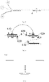
FIG. 1 is a schematic structural diagram of a die-cutting lamination system according to an embodiment of the present disclosure; -
FIG. 2 is a schematic structural diagram of a die-cutting lamination system according to another embodiment of the present disclosure; -
FIG. 3 is a schematic diagram showing lengths of a positive electrode sheet and a negative electrode sheet according to an embodiment of the present disclosure; -
FIG. 4 is a schematic diagram showing transferring and stacking of lamination units by using a clamping jaw and auxiliary rollers according to an embodiment of the present disclosure; -
FIG. 5 is a schematic diagram of a die-cutting lamination system with a clamping jaw clamping a lamination unit according to an embodiment of the present disclosure; -
FIG. 6 is a schematic diagram of a die-cutting lamination system at a start of lamination according to an embodiment of the present disclosure; and -
FIG. 7 is a schematic diagram of a die-cutting lamination system at an end of lamination according to an embodiment of the present disclosure. - It should be noted that, in the present disclosure, the embodiments and the features of the embodiments may be combined with each other without conflict.
- According to a first aspect of the present disclosure, a die-cutting lamination system is provided. According to an embodiment of the present disclosure, as illustrated in
FIG. 1 orFIG. 2 , the system includes anunwinding mechanism 100, an electrode-winding cutting mechanism 200, a preheating androlling device 300, adetection apparatus 400, aseparator cutting mechanism 500, and alamination apparatus 600. - The die-cutting lamination system described above will be described in detail with embodiments with reference to
FIGS. 1 to 7 . - According to the embodiments of the present disclosure, the
unwinding mechanism 100 includes a negativeelectrode unwinding mechanism 110, aseparator unwinding mechanism 120, and a positiveelectrode unwinding mechanism 130, the negativeelectrode unwinding mechanism 110 and the positiveelectrode unwinding mechanism 130 are arranged on an upper side and a lower side of theseparator unwinding mechanism 120, and the negativeelectrode unwinding mechanism 110 and/or the positiveelectrode unwinding mechanism 130 is configured to operate at intervals relative to theseparator unwinding mechanism 120. The electrode-winding cutting mechanism 200 is arranged downstream of theunwinding mechanism 100, and the electrode-winding cutting mechanism 200 includes a negativeelectrode cutting mechanism 210 and a positiveelectrode cutting mechanism 220. The negativeelectrode cutting mechanism 210 is configured to cooperate with the negativeelectrode unwinding mechanism 110 and cut negative electrode sheets, and the positiveelectrode cutting mechanism 130 is configured to cooperate with the positiveelectrode unwinding mechanism 220 and cut positive electrode sheets, in such a manner that a laminated layer including a separator, the negative electrode sheets, and the positive electrode sheets is obtained, the negative electrode sheets and the positive electrode sheets being distributed on an upper side and a lower side of the separator. - According to the embodiments of the present disclosure, as illustrated in
FIG. 1 orFIG. 2 , the laminated layer including the separator and the negative electrode sheets and the positive electrode sheets that are distributed on the upper side and the lower side of the separator includes two parts, one part includes three-layer structures in each of which one negative electrode sheet and one positive electrode sheet are distributed on the upper side and the lower side of the separator and centers of the negative electrode sheet, the positive electrode sheet, and the separator are aligned, and the other part includes single-layer separator structures containing no positive electrode sheet and no negative electrode sheet. The three-layer structures are roller-pressed by a rolling apparatus to form positive-negative electrode sheet lamination units A, and the single-layer separator structures form separator lamination units B. - According to an embodiment of the present disclosure, an unwinding speed of the positive electrode unwinding mechanism and an unwinding speed of the negative electrode unwinding mechanism and a cutting interval of the positive electrode cutting mechanism and a cutting interval of the negative electrode cutting mechanism can be adjusted comprehensively, so that a length of the positive electrode sheet that has been cut is smaller than a length of the cut negative electrode sheet, and a horizontal distance between every two adjacent positive-negative electrode sheet lamination units is 1mm to 6mm larger than the length of the cut negative electrode sheet, in such a manner that the length of the separator, the length of the negative electrode sheet, and the length of the positive electrode sheet decrease in order in the finally obtained electrode assembly. For example, the length of the negative electrode sheet can be 0.5mm to 3 mm smaller than the length of the separator. As illustrated in
FIG. 3 , a length difference d between each side of the positive electrode sheet and a corresponding side of the negative electrode sheet can be 0.5mm to 1.5mm, ensuring that the electrode assembly has high safety and stability. It should be noted that the length described in the present disclosure is defined in terms of a moving direction of the electrode sheets, and can also be understood as the length of a respective side. - According to still another embodiment of the present disclosure, as illustrated in
FIG. 1 orFIG. 2 , the die-cutting lamination system may further include a plurality oftension rollers 700, and the plurality oftension rollers 700 are arranged between theunwinding mechanism 100 and the electrode-winding cutting mechanism 200 and are distributed on upper and/or lower sides of the negative electrode sheet, the separator, and the positive electrode sheet at intervals, thereby facilitating unwinding and starting and stopping of the electrode sheets and the separator. - According to another embodiment of the present disclosure, the negative
electrode unwinding mechanism 110, theseparator unwinding mechanism 120, and the positiveelectrode unwinding mechanism 130 in theunwinding mechanism 100 may be distributed from top to bottom (as illustrated inFIG. 1 ) or from bottom to top (as illustrated inFIG. 2 ). - According to the embodiments of the present disclosure, the preheating and rolling
device 300 includes a preheating apparatus (not individually shown) and a rolling apparatus (not individually shown) that are sequentially connected, the preheating apparatus is arranged between theunwinding mechanism 110 and the rolling apparatus, the rolling apparatus is arranged downstream of the electrode-winding cutting mechanism 200, and the rolling apparatus is configured to enable the positive electrode sheets and the negative electrode sheets of the laminated layer to be respectively adhered to the separator to obtain a laminate including alternately distributed positive-negative electrode sheet lamination units and separator lamination units. - According to an embodiment of the present disclosure, the preheating apparatus can preheat the separator, the positive electrode sheet, and the negative electrode sheet before the electrode sheets are cut, so that the preheating time can be longer, and an adhesion effect of the roller-pressed electrode sheets and separator can be further improved.
- According to the embodiments of the present disclosure, the
detection apparatus 400 is arranged downstream of the preheating and rollingdevice 300, and configured to detect whether the laminate has a defect. Thedetection apparatus 400 can detect a position, a size, a wrinkle, a tab wrinkle, a folded edge, an unfilled corner and the like of the electrode sheets/separator, so that defective lamination units can be discarded in time; further, when the lamination units are under detection with the detection apparatus, there is no need for the lamination units to be transferred, it is no longer necessary to separately and additionally provide a positioning platform and a group of manipulators, and the structure is simpler. Thedetection apparatus 400 may be a CCD detection mechanism. - According to the embodiments of the present disclosure, the
separator cutting mechanism 500 includes a firstseparator cutting mechanism 510 and a secondseparator cutting mechanism 520. The firstseparator cutting mechanism 510 is arranged upstream of the secondseparator cutting mechanism 520, and configured to cut and discharge, based on a detection result of the detection apparatus, a defective positive-negative electrode sheet lamination unit/a defective separator lamination unit and a separator lamination unit/a positive-negative electrode sheet lamination unit adjacent to the defective positive-negative electrode sheet lamination unit/the defective separator lamination unit in pairs. The secondseparator cutting mechanism 520 is configured to perform separator cutting on a last qualified lamination unit based on a number of layers to be laminated. It should be noted that, in order to ensure the accuracy of subsequent lamination, when a lamination unit has a defect, the positive-negative electrode sheet lamination unit and the separator lamination unit need to be discharged in pairs, for example, if one positive-negative electrode sheet lamination unit has a defect, one separator lamination unit needs to be discarded at the same time; in addition, the separator between lamination units having no defect is not cut off in the subsequent lamination process, and the separator is cut off by the second separator cutting mechanism only after the lamination is finished, so that the number of times for cutting the separator is very small, and a risk of the separator wrinkling to expose the electrode sheets in the lamination process is greatly reduced. - According to an embodiment of the present disclosure, the die-cutting lamination system may further include a
discharger 800, and thedischarger 800 may be arranged downstream of thedetection apparatus 400 and configured to cooperate with the firstseparator cutting mechanism 510 to discharge a defective lamination unit based on the display of thedetection apparatus 400. Thedischarger 800 may be an NG discharger. - According to the embodiments of the present disclosure, the
lamination apparatus 600 is arranged downstream of theseparator cutting mechanism 500 and configured to stack the positive-negative electrode sheet lamination units A and the separator lamination units B alternately, thereby obtaining an electrode assembly including a plurality of layers of positive electrode sheet and a plurality of layers of negative electrode sheet. - According to an embodiment of the present disclosure, as illustrated in
FIGS. 1 to 2 orFIG. 4 , thelamination apparatus 600 may include a clampingjaw 610, a firstauxiliary roller 620, and a secondauxiliary roller 630, the clampingjaw 610 and the firstauxiliary roller 620 are movable and are configured to cooperate with the secondauxiliary roller 630 in such a manner that the positive-negative electrode sheet lamination units and the separator lamination units are spread, aligned and alternately stacked. When the lamination apparatus is used to transfer and laminate lamination units, the clamping jaw clamps the laminate from upper and lower sides of the lamination units (as illustrated inFIG. 5 , the clamping jaw can clamp the laminate from an upper side and a lower side that are perpendicular to a moving direction of the electrode sheets), and the first auxiliary roller and the second auxiliary roller cooperate with the clamping jaw to realize the stacking of two adjacent lamination units, and assist in the alignment of the lamination units; the position of the second auxiliary roller is relatively fixed and can be finely adjusted, and the tension of the lamination units is controlled by adjusting the first auxiliary roller and the second auxiliary roller, so that the lamination units are alternately stacked and aligned; in addition, the lamination manner of the present disclosure using the cooperation of the clamping jaw with the auxiliary rollers is a horizontal lamination manner, which is not only more conducive to lamination alignment and but also allows a smaller space occupancy rate of the system in the vertical direction, compared with a vertical lamination manner; further, in the present disclosure, the clamping jaw is adopted to replace a negative pressure manipulator to realize the transfer of lamination units, which can effectively avoid a risk of dropping of a lower separator and/or a lower electrode sheet of a lamination unit when sucking an upper side of the lamination unit to transfer the lamination unit. - According to another embodiment of the present disclosure, the
lamination apparatus 600 includes two sets of the firstauxiliary roller 620 and the secondauxiliary roller 630. One set is in an operating state in which the auxiliary rollers cooperate with the clamping jaw to stack and align two adjacent lamination units, the other set is in a ready state for stacking and aligning a next pair of lamination units, and after the two adjacent lamination units are stacked and aligned, the auxiliary rollers in the operating state are withdrawn and enter the ready state. For example, as illustrated inFIG. 4 (FIG. 4 is a schematic diagram showing a start of lamination of one electrode assembly with the negative electrode sheet located above the separator and the positive electrode sheet located below the separator), the auxiliary rollers are in the ready state, the firstauxiliary roller 620 is located at position 1, and the secondauxiliary roller 630 is located atposition 2; when the clampingjaw 610 clamps a lamination unit and transfers the lamination unit to the lamination position, the set of auxiliary rollers is put into operation, the firstauxiliary roller 620 is transferred to position 3, the position of the second auxiliary roller is basically unchanged, and the second auxiliary roller is only finely adjusted at the original position to aid in aligning the lamination unit, and at this time, the other set of auxiliary rollers is let ready at position 1 andposition 2. - According to another embodiment of the present disclosure, as illustrated in
FIG. 6 , when the negativeelectrode unwinding mechanism 110, theseparator unwinding mechanism 120, and the positiveelectrode unwinding mechanism 130 in theunwinding mechanism 100 are distributed from top to bottom, the negative electrode sheet is positioned above the separator, the positive electrode sheet is positioned below the separator, one negative electrode lamination unit is pre-stacked, and then a plurality of separator lamination units B and a plurality of positive-negative electrode sheet lamination units A are stacked alternately; as illustrated inFIG. 7 , when the negativeelectrode unwinding mechanism 110, theseparator unwinding mechanism 120, and the positiveelectrode unwinding mechanism 130 in theunwinding mechanism 100 are distributed from bottom to top, the positive electrode sheet is positioned above the separator, the negative electrode sheet is positioned below the separator, a plurality of separator lamination units and a plurality of positive-negative electrode sheet lamination units are pre-stacked alternately, and then one negative electrode lamination unit is stacked. The negative electrode lamination unit includes a layer of negative electrode sheet and a layer of separator. - Specifically, when the negative electrode sheet is positioned above the separator and the positive electrode sheet is positioned below the separator, in a stacking period of a single electrode assembly, before a first positive-negative electrode sheet lamination unit A is formed, the unwinding of the positive electrode unwinding mechanism is suspended, and only the negative electrode unwinding mechanism and the separator unwinding mechanism perform unwinding, until a first cutting operation of the negative electrode cutting mechanism is completed and a negative electrode lamination unit including a separator and a negative electrode sheet positioned on the separator is obtained; subsequently, the unwinding of the negative electrode unwinding mechanism is suspended, and only the separator unwinding mechanism continues the unwinding operation to form a separator lamination unit B; then the unwinding of the negative electrode unwinding mechanism and the unwinding of the negative electrode unwinding mechanism are started or suspended synchronously to obtain a laminated layer containing alternately staked positive-negative electrode sheet lamination units A and separator lamination units B by adjusting the unwinding speeds of the unwinding mechanisms or the cutting intervals of the electrode sheet cutting mechanisms, and during lamination, one negative electrode lamination unit is stacked first and then the positive-negative electrode sheet lamination units A and the separator lamination units B are stacked alternately with the last lamination unit being a separator lamination unit B; after lamination is completed, the separator is cut, then an adhesive tape is affixed, and blanking is performed. On the contrary, when the positive electrode sheet is positioned above the separator and the negative electrode sheet is positioned below the separator, a laminated layer containing alternately stacked separator lamination units B and positive-negative electrode sheet lamination units A is formed first, i.e., the separator lamination units B and the positive-negative electrode sheet lamination units A are sequentially and alternately stacked, and the last lamination unit is a negative electrode lamination unit containing no positive electrode sheet.
- In summary, the die-cutting lamination system of the present disclosure has the following advantages: (1) according to the present disclosure, the die-cutting apparatus and the lamination apparatus are integrated in the die-cutting lamination system, on the one hand, a feeding cartridge is omitted, and a limitation of feeding with the cartridge is broken through, on the other hand, the electrode sheets are adhered to the separator through preheating and roller pressing, the lamination feed is a roll material instead of a single sheet feed, and continuous feeding can be achieved, which can break through a limitation of the mechanical structure, increase the lamination speed, and reduce a system fault rate; (2) the number of lamination machines can be greatly reduced, the acquisition cost of the devices is reduced, the energy consumption of the device is reduced, and a theoretical lamination speed can reach 0.25s/sheet to 0.5s/sheet; (3) an edge shape of the separator after the separator is cut cannot be ensured and a risk of the separator wrinkling to expose the electrode sheets exists in the lamination process; instead, the separator between lamination units containing no defect is not cut during the lamination process using the die-cutting lamination system, but is cut only after the lamination process is finished, and a number of cuttings of the separator is very small, which greatly reduces the risk of the separator wrinkling to expose the electrode sheets; (4) if each lamination unit is cut off separately and then detected and laminated, the cut lamination units need to be transferred to a positioning platform and then transferred to a lamination platform after being detected by a detection apparatus, namely, an additional group of manipulators and an additional positioning platform need to be added; instead, when the die-cutting lamination system disclosed by the present disclosure is adopted to detect the lamination units, there is no need to separately provide an additional positioning platform or an additional group of manipulators, and the structure is simpler; (5) the lamination of the system can be conducted in a horizontal manner, thereby facilitating lamination alignment and reducing a space occupation of the system in the vertical direction.
- According to a second aspect of the present disclosure, the present disclosure provides a die-cutting lamination method using the die-cutting lamination system. Referring to
FIG. 1 orFIG. 2 , according to embodiments of the present disclosures, the method includes: (1) providing, by the unwinding mechanisms, electrode sheets and a separator, enabling the negative electrode cutting mechanism to cooperate with the negative electrode unwinding mechanism and cut negative electrode sheets, and enabling the positive electrode cutting mechanism to cooperate with the positive electrode unwinding mechanism and cut positive electrode sheets, to obtain a laminated layer including the separator, the negative electrode sheets, and the positive electrode sheets, the negative electrode sheets and the positive electrode sheets being distributed on an upper side and a lower side of the separator; (2) preheating, by the preheating apparatus, the separator, and the positive electrode sheets and the negative electrode sheets before and after cutting, and roller pressing, by the rolling apparatus, the laminated layer to respectively adhere the positive electrode sheets and the negative electrode sheets of the laminated layer to the separator to obtain a laminate including alternately distributed positive-negative electrode sheet lamination units and separator lamination units; (3) detecting, by the detection apparatus, whether the laminate has a defect, and cutting and discharging, by the first separator cutting mechanism, based on a detection result of the detection apparatus, a defective positive-negative electrode sheet lamination unit/a defective separator lamination unit and a separator lamination unit/a positive-negative electrode sheet lamination unit adjacent to the defective positive-negative electrode sheet lamination unit/the defective separator lamination unit in pairs; (4) alternately stacking, by the lamination apparatus, the positive-negative electrode sheet lamination units and the separator lamination units, and performing separator cutting, by the second separator cutting mechanism, on a last qualified lamination unit based on a number of layers to be laminated to obtain an electrode assembly. - According to an embodiment of the present disclosure, the lamination units may be stacked by the clamping jaw, the first auxiliary roller, and the second auxiliary roller in cooperation to obtain the electrode assembly in which positive-negative electrode sheet lamination units and separator sheet lamination units are spread, aligned, and alternately stacked. The lamination manner is a horizontal lamination manner, and compared with the vertical lamination manner, the horizontal lamination manner is more favorable for the alignment of the lamination and the system occupies smaller space in the vertical direction; further, according to the present disclosure, the clamping jaw is adopted to replace the negative pressure manipulator to realize the transfer of lamination units, which can effectively avoid a risk of dropping of a lower electrode sheet and/or a separator of a lamination unit when sucking an upper side of the lamination unit to transfer the lamination unit.
- According to still another embodiment of the present disclosure, a length of each positive electrode sheet in the finally obtained electrode assembly is smaller than a length of each negative electrode sheet in the finally obtained electrode assembly, for example, by 0.5mm to 3mm or 0.5mm to 1.5mm, and the length of each negative electrode sheet in the finally obtained electrode assembly may be 0.5mm to 3mm smaller than a length of each separator in the finally obtained electrode assembly. The risk of exposing the electrode sheets can thereby be avoided.
- According to yet another specific embodiment of the present disclosure, when the negative electrode sheet is positioned above the separator and the positive electrode sheet is positioned below the separator, one negative electrode lamination unit is pre-stacked, and then a plurality of separator lamination units and a plurality of positive-negative electrode sheet lamination units are stacked alternately; and when the positive electrode sheet is positioned above the separator and the negative electrode sheet is positioned below the separator, a plurality of separator lamination units and a plurality of positive-negative electrode sheet lamination units are alternately pre-stacked, and then one negative electrode sheet lamination unit is stacked.
- In summary, the die-cutting lamination method of the present disclosure has the following advantages. (1) According to the method, the electrode sheet cutting and lamination are coupled together, on the one hand, a feeding cartridge is omitted, and a limitation of feeding with the cartridge is broken through, on the other hand, the electrode sheets are adhered to the separator through preheating and roller pressing to form the lamination units, the lamination feed is a roll material instead of a single sheet feed, and continuous feeding can be achieved, which can break through a limitation of the mechanical structure, increase the lamination speed, and reduce a system fault rate; (2) the electrode sheets and the separator are laminated synchronously, the lamination speed is fast, and a theoretical lamination speed can reach 0.25s/sheet to 0.5s/sheet; (3) a number of cuttings of the separator is very small, which greatly reduces a risk of the separator wrinkling to expose the electrode sheets; (4) compared with a manner that each lamination unit is cut off separately and then detected and laminated, there is no need to transfer lamination units during detection of the lamination units, and the process is simpler; and (5) the lamination manner can be a horizontal lamination manner, which is more favorable to the lamination alignment compared with the vertical lamination manner. It should be noted that features and effects described above for the die-cutting lamination system are also applicable to the die-cutting lamination method, which will not be elaborated here.
- The above description merely illustrates the preferred embodiments of the present disclosure and is not intended to limit the present disclosure. Any modification, equivalent substitution, or improvement, etc. made within the essence and principles of the present disclosure shall fall within the protection scope of the present disclosure.
Claims (10)
- A die-cutting lamination system, comprising:unwinding mechanisms comprising a negative electrode unwinding mechanism, a separator unwinding mechanism, and a positive electrode unwinding mechanism, wherein the negative electrode unwinding mechanism and the positive electrode unwinding mechanism are arranged on an upper side and a lower side of the separator unwinding mechanism, and the negative electrode unwinding mechanism and/or the positive electrode unwinding mechanism is configured to operate at intervals relative to the separator unwinding mechanism;an electrode-winding cutting mechanism arranged downstream of the unwinding mechanisms and comprising a negative electrode cutting mechanism and a positive electrode cutting mechanism, wherein the negative electrode cutting mechanism is configured to cooperate with the negative electrode unwinding mechanism and cut negative electrode sheets, the positive electrode cutting mechanism is configured to cooperate with the positive electrode unwinding mechanism and cut positive electrode sheets, in such a manner that a laminated layer comprising a separator, the negative electrode sheets, and the positive electrode sheets is obtained, the negative electrode sheets and the positive electrode sheets being distributed on an upper side and a lower side of the separator;a preheating and rolling device comprising a preheating apparatus and a rolling apparatus which are sequentially connected, wherein the preheating apparatus is arranged between the unwinding mechanisms and the rolling apparatus, the rolling apparatus is arranged downstream of the electrode-winding cutting mechanism, and the rolling apparatus is configured to enable the positive electrode sheets and the negative electrode sheets of the laminated layer to be respectively adhered to the separator to obtain a laminate comprising alternately distributed positive-negative electrode sheet lamination units and separator lamination units;a detection apparatus arranged downstream of the preheating and rolling device and configured to detect whether the laminate has a defect;separator cutting mechanisms comprising a first separator cutting mechanism and a second separator cutting mechanism, wherein the first separator cutting mechanism is arranged upstream of the second separator cutting mechanism, and configured to cut and discharge, based on a detection result of the detection apparatus, a defective positive-negative electrode sheet lamination unit/a defective separator lamination unit and a separator lamination unit/a positive-negative electrode sheet lamination unit adjacent to the defective positive-negative electrode sheet lamination unit/the defective separator lamination unit in pairs, and the second separator cutting mechanism is configured to perform separator cutting on a last qualified lamination unit based on a number of layers to be laminated; anda lamination apparatus arranged downstream of the separator cutting mechanisms and configured to stack the positive-negative electrode sheet lamination units and the separator lamination units alternately.
- The die-cutting lamination system according to claim 1, wherein the lamination apparatus comprises a clamping jaw, a first auxiliary roller, and a second auxiliary roller, and the clamping jaw and the first auxiliary roller are movable and are configured to cooperate with the second auxiliary roller to enable the positive-negative electrode sheet lamination units and the separator lamination units to be spread, aligned and alternately stacked.
- The die-cutting lamination system according to claim 1 or 2, wherein the negative electrode unwinding mechanism, the separator unwinding mechanism, and the positive electrode unwinding mechanism are distributed from top to bottom or from bottom to top among the unwinding mechanisms.
- The die-cutting lamination system according to any one of claims 1 to 3, further comprising a plurality of tension rollers, the plurality of tension rollers being arranged between the unwinding mechanisms and the electrode-winding cutting mechanism and distributed on upper and/or lower sides of the negative electrode sheets, the separator, and the positive electrode sheets at intervals.
- The die-cutting lamination system according to any one of claims 1 to 4, wherein a length of each of the cut positive electrode sheets is smaller than a length of each of the cut negative electrode sheets; and a horizontal distance between every two adjacent positive-negative electrode sheet lamination units is 1mm to 6mm greater than the length of each of the negative electrode sheets.
- The die-cutting lamination system according to any one of claims 1 to 5, further comprising a discharger arranged downstream of the detection apparatus, wherein the discharger is configured to cooperate with the first separator cutting mechanism to discharge a defective lamination unit.
- A die-cutting lamination method using the die-cutting lamination system according to any one of claims 1 to 6, comprising:(1) providing, by the unwinding mechanisms, electrode sheets and a separator, enabling the negative electrode cutting mechanism to cooperate with the negative electrode unwinding mechanism and cut negative electrode sheets, and enabling the positive electrode cutting mechanism to cooperate with the positive electrode unwinding mechanism and cut positive electrode sheets, to obtain a laminated layer comprising a separator, the negative electrode sheets, and the positive electrode sheets, the negative electrode sheets and the positive electrode sheets being distributed on an upper side and a lower side of the separator;(2) preheating, by the preheating apparatus, the separator, and the positive electrode sheets and the negative electrode sheets before and after the cutting, and roller-pressing, by the rolling apparatus, the laminated layer to respectively adhere the positive electrode sheets and the negative electrode sheets of the laminated layer to the separator to obtain a laminate comprising alternately distributed positive-negative electrode sheet lamination units and separator lamination units;(3) detecting, by the detection apparatus, whether the laminate has a defect, and cutting and discharging, by the first separator cutting mechanism, based on a detection result of the detection apparatus, a defective positive-negative electrode sheet lamination unit/a defective separator lamination unit and a separator lamination unit/a positive-negative electrode sheet lamination unit adjacent to the defective positive-negative electrode sheet lamination unit/the defective separator lamination unit in pairs; and(4) alternately stacking, by the lamination apparatus, the positive-negative electrode sheet lamination units and the separator lamination units, and performing separator cutting, by the second separator cutting mechanism, on a last qualified lamination unit based on a number of layers to be laminated to obtain an electrode assembly.
- The method according to claim 7, wherein a length of each positive electrode sheet in the electrode assembly is smaller than a length of each negative electrode sheet in the electrode assembly, and the length of each negative electrode sheet in the electrode assembly is 0.5mm to 3mm smaller than a length of each separator in the electrode assembly.
- The method according to claim 7 or 8, further comprising:
stacking, by the clamping jaw, the first auxiliary roller, and the second auxiliary roller in cooperation, lamination units to obtain the electrode assembly in which the positive-negative electrode sheet lamination units and the separator lamination units are spread, aligned, and alternately stacked. - The method according to any one of claims 7 to 9, further comprising:positioning the negative electrode sheet above the separator, positioning the positive electrode sheet below the separator, pre-stacking one negative electrode lamination unit, and then alternately stacking a plurality of separator lamination units and a plurality of positive-negative electrode sheet lamination units; orpositioning the positive electrode sheet above the separator, positioning the negative electrode sheet below the separator, alternately pre-stacking a plurality of separator lamination units and a plurality of positive-negative electrode sheet lamination units, and then stacking one negative electrode lamination unit.
Applications Claiming Priority (2)
| Application Number | Priority Date | Filing Date | Title |
|---|---|---|---|
| CN201910641926.1A CN110380128B (en) | 2019-07-16 | 2019-07-16 | Die-cut lamination system and method |
| PCT/CN2020/102127 WO2021008555A1 (en) | 2019-07-16 | 2020-07-15 | Die-cutting lamination system and method |
Publications (2)
| Publication Number | Publication Date |
|---|---|
| EP4002541A1 true EP4002541A1 (en) | 2022-05-25 |
| EP4002541A4 EP4002541A4 (en) | 2023-08-16 |
Family
ID=68253601
Family Applications (1)
| Application Number | Title | Priority Date | Filing Date |
|---|---|---|---|
| EP20839786.9A Pending EP4002541A4 (en) | 2019-07-16 | 2020-07-15 | DIE LAMINATING SYSTEM AND METHOD |
Country Status (4)
| Country | Link |
|---|---|
| EP (1) | EP4002541A4 (en) |
| KR (1) | KR102728999B1 (en) |
| CN (1) | CN110380128B (en) |
| WO (1) | WO2021008555A1 (en) |
Cited By (2)
| Publication number | Priority date | Publication date | Assignee | Title |
|---|---|---|---|---|
| FR3122607A1 (en) * | 2022-08-18 | 2022-11-11 | Verkor | Method of manufacturing a battery cell |
| KR102836260B1 (en) * | 2024-05-24 | 2025-07-22 | 주식회사 이알시스템 | apparatus and method for cutting cathode materials of laminating process of secondary battery |
Families Citing this family (24)
| Publication number | Priority date | Publication date | Assignee | Title |
|---|---|---|---|---|
| CN110380128B (en) * | 2019-07-16 | 2020-06-30 | 蜂巢能源科技有限公司 | Die-cut lamination system and method |
| CN110808382B (en) * | 2019-11-26 | 2024-10-29 | 无锡先导智能装备股份有限公司 | Lamination device and lamination method |
| CN110890582A (en) * | 2019-11-26 | 2020-03-17 | 无锡先导智能装备股份有限公司 | Lamination device and lamination method |
| CN111313100B (en) * | 2020-03-09 | 2025-01-03 | 无锡先导智能装备股份有限公司 | Lamination device |
| CN111430770A (en) * | 2020-03-31 | 2020-07-17 | 蜂巢能源科技有限公司 | Die-cut lamination processing device |
| CN111769333A (en) * | 2020-06-29 | 2020-10-13 | 合肥国轩高科动力能源有限公司 | A new lamination method based on cutting and stacking machine |
| CN111934024B (en) * | 2020-06-30 | 2022-02-22 | 蜂巢能源科技有限公司 | Turret lamination method, turret lamination device and battery pole piece thermal composite lamination system |
| CN112151879B (en) * | 2020-10-13 | 2022-04-01 | 厦门美力新能源科技有限公司 | Lithium battery pole piece lamination equipment and lamination method thereof |
| CN112635700B (en) * | 2020-12-18 | 2022-04-01 | 蜂巢能源科技有限公司 | Device for preparing battery pole group, method for preparing battery pole group, and battery pole group |
| CN112652802B (en) * | 2020-12-30 | 2022-12-13 | 蜂巢能源科技有限公司 | Lamination device |
| KR102940113B1 (en) * | 2021-02-04 | 2026-03-16 | 주식회사 엘지에너지솔루션 | Lamination apparatus and method of discharging defective elecrode cell assembly of the same |
| CN113451659B (en) * | 2021-05-21 | 2022-09-30 | 广州中国科学院工业技术研究院 | Lithium battery positive and negative electrode synchronous lamination device and lamination method |
| CN113422113B (en) * | 2021-06-04 | 2022-07-05 | 深圳赛骄阳能源科技股份有限公司 | Method for manufacturing special-shaped lithium ion battery |
| CN113517465A (en) * | 2021-07-14 | 2021-10-19 | 恒大新能源技术(深圳)有限公司 | Lamination equipment, battery cell and preparation method of battery cell |
| CN113745635B (en) * | 2021-11-05 | 2022-03-01 | 三一技术装备有限公司 | Lamination device and lamination method |
| CN114122528B (en) * | 2021-11-25 | 2023-07-21 | 蜂巢能源科技有限公司 | Electrode Cutting Conveyor and Lamination System |
| IT202100030239A1 (en) * | 2021-11-30 | 2023-05-30 | P I T S R L | MACHINE FOR THE CREATION OF ELECTRIC ENERGY STORAGE DEVICES |
| WO2023100210A1 (en) * | 2021-11-30 | 2023-06-08 | P.I.T. S.R.L. | Apparatus for forming an electrode strip for electrical energy storage devices |
| CN116314999A (en) * | 2021-12-21 | 2023-06-23 | 宁德时代新能源科技股份有限公司 | Electrode assembly manufacturing apparatus and manufacturing method |
| CN114335671B (en) * | 2021-12-31 | 2024-05-03 | 三一技术装备有限公司 | Pole piece compounding mechanism and lamination device |
| CN114975882B (en) * | 2022-05-31 | 2023-07-14 | 蜂巢能源科技股份有限公司 | Battery pole piece slicing system control method, device and battery pole piece slicing system |
| WO2024001417A1 (en) * | 2022-06-27 | 2024-01-04 | 比亚迪股份有限公司 | Lamination device, lamination method, laminated battery cell, and battery |
| CN115839959A (en) * | 2022-11-03 | 2023-03-24 | 宁德时代新能源科技股份有限公司 | Tab detection system and tab detection method |
| CN117429935B (en) * | 2023-10-08 | 2024-06-07 | 深圳市经纬线科技有限公司 | Film cutting machine with rubberizing device and rubberizing method thereof |
Family Cites Families (14)
| Publication number | Priority date | Publication date | Assignee | Title |
|---|---|---|---|---|
| KR101531234B1 (en) * | 2012-11-15 | 2015-06-24 | 에스케이이노베이션 주식회사 | High-Speed Staking Apparatus for Secondary Battery and Method of the same |
| KR101749148B1 (en) * | 2014-10-23 | 2017-06-20 | 주식회사 엘지화학 | Lamination Device Using High-frequency Induction Heating and Secondary Battery Manufactured Using the Same |
| CN104934628B (en) * | 2015-06-05 | 2020-04-10 | 深圳吉阳智云科技有限公司 | Battery cell preparation system and method with pole piece and diaphragm detection function |
| CN104934627B (en) * | 2015-06-05 | 2020-02-14 | 深圳吉阳智云科技有限公司 | Battery cell preparation system and method with pole piece defective product elimination function |
| CN106025374A (en) * | 2016-05-29 | 2016-10-12 | 合肥国轩高科动力能源有限公司 | A method of manufacturing a laminated battery |
| US11189860B2 (en) * | 2016-07-28 | 2021-11-30 | Sanyo Electric Co., Ltd. | Method of manufacturing secondary battery |
| CN206921957U (en) * | 2017-04-11 | 2018-01-23 | 深圳吉阳智能科技有限公司 | Pole piece bad product device for eliminating for lithium battery winder |
| CN207490030U (en) * | 2017-11-02 | 2018-06-12 | 合肥国轩高科动力能源有限公司 | A high-efficiency lamination unit processing system |
| CN207651617U (en) * | 2017-11-28 | 2018-07-24 | 深圳吉阳智能科技有限公司 | A kind of lamination device of combined type laminated cell |
| CN109301349A (en) * | 2018-09-12 | 2019-02-01 | 深圳市海目星激光智能装备股份有限公司 | A lamination process and lamination device |
| CN109244554B (en) * | 2018-09-21 | 2020-12-29 | 江苏卡耐新能源有限公司 | Z-shaped lamination equipment and process for lithium ion battery |
| CN109346778A (en) * | 2018-10-08 | 2019-02-15 | 东莞阿李自动化股份有限公司 | A method of manufacturing a laminated battery |
| KR102692319B1 (en) * | 2018-12-06 | 2024-08-07 | 현대자동차주식회사 | Cell stacking apparatus and manufacturing system for secondary battery |
| CN110380128B (en) * | 2019-07-16 | 2020-06-30 | 蜂巢能源科技有限公司 | Die-cut lamination system and method |
-
2019
- 2019-07-16 CN CN201910641926.1A patent/CN110380128B/en active Active
-
2020
- 2020-07-15 KR KR1020227005223A patent/KR102728999B1/en active Active
- 2020-07-15 EP EP20839786.9A patent/EP4002541A4/en active Pending
- 2020-07-15 WO PCT/CN2020/102127 patent/WO2021008555A1/en not_active Ceased
Cited By (2)
| Publication number | Priority date | Publication date | Assignee | Title |
|---|---|---|---|---|
| FR3122607A1 (en) * | 2022-08-18 | 2022-11-11 | Verkor | Method of manufacturing a battery cell |
| KR102836260B1 (en) * | 2024-05-24 | 2025-07-22 | 주식회사 이알시스템 | apparatus and method for cutting cathode materials of laminating process of secondary battery |
Also Published As
| Publication number | Publication date |
|---|---|
| KR20220035209A (en) | 2022-03-21 |
| CN110380128A (en) | 2019-10-25 |
| KR102728999B1 (en) | 2024-11-11 |
| EP4002541A4 (en) | 2023-08-16 |
| WO2021008555A1 (en) | 2021-01-21 |
| CN110380128B (en) | 2020-06-30 |
Similar Documents
| Publication | Publication Date | Title |
|---|---|---|
| EP4002541A1 (en) | Die-cutting lamination system and method | |
| EP4002542A1 (en) | Die-cutting and lamination system and method | |
| WO2021008554A1 (en) | Die-cutting lamination system and method | |
| TWI472080B (en) | A position detecting device and a position detecting method | |
| WO2022179621A1 (en) | Battery cell and lamination apparatus | |
| CN104106170B (en) | Battery press device and battery pressing method | |
| CN106328981A (en) | Laminated cell preparation device | |
| CN112652802B (en) | Lamination device | |
| CN220367974U (en) | Bag-making laminated battery cell of composite anode and production equipment | |
| WO2025067572A2 (en) | Winding apparatus, battery processing apparatus and battery production line | |
| CN211700479U (en) | Thermal composite high-speed lamination machine | |
| KR102644861B1 (en) | Device for folding electrode assembly | |
| CN219180560U (en) | Pole core preparation device | |
| CN216966414U (en) | A high-speed slicing device and lamination equipment | |
| CN119674252B (en) | Lithium-ion battery cutting and stacking integrated machine and its manufacturing process | |
| CN211045614U (en) | Lamination machine | |
| CN221262440U (en) | Cutting and stacking equipment | |
| CN217881611U (en) | Lamination production line | |
| WO2025020961A1 (en) | Battery cell winding apparatus and battery cell winding method | |
| CN115036556B (en) | A lamination device and lamination production line | |
| CN115000528A (en) | A lamination device and lamination machine | |
| CN117525534A (en) | Solid-state battery manufacturing apparatus | |
| CN212625734U (en) | Lamination unit production system | |
| CN116864825A (en) | Method and system for manufacturing cathode continuous solid-state battery and solid-state battery | |
| CN217691274U (en) | Lamination production line |
Legal Events
| Date | Code | Title | Description |
|---|---|---|---|
| STAA | Information on the status of an ep patent application or granted ep patent |
Free format text: STATUS: THE INTERNATIONAL PUBLICATION HAS BEEN MADE |
|
| PUAI | Public reference made under article 153(3) epc to a published international application that has entered the european phase |
Free format text: ORIGINAL CODE: 0009012 |
|
| STAA | Information on the status of an ep patent application or granted ep patent |
Free format text: STATUS: REQUEST FOR EXAMINATION WAS MADE |
|
| 17P | Request for examination filed |
Effective date: 20220215 |
|
| AK | Designated contracting states |
Kind code of ref document: A1 Designated state(s): AL AT BE BG CH CY CZ DE DK EE ES FI FR GB GR HR HU IE IS IT LI LT LU LV MC MK MT NL NO PL PT RO RS SE SI SK SM TR |
|
| DAV | Request for validation of the european patent (deleted) | ||
| DAX | Request for extension of the european patent (deleted) | ||
| A4 | Supplementary search report drawn up and despatched |
Effective date: 20230719 |
|
| RIC1 | Information provided on ipc code assigned before grant |
Ipc: H01M 10/0583 20100101AFI20230713BHEP |