EP4002269A1 - Systems and methods for image-based object modeling using multiple image acquisitions or reconstructions - Google Patents
Systems and methods for image-based object modeling using multiple image acquisitions or reconstructions Download PDFInfo
- Publication number
- EP4002269A1 EP4002269A1 EP21217448.6A EP21217448A EP4002269A1 EP 4002269 A1 EP4002269 A1 EP 4002269A1 EP 21217448 A EP21217448 A EP 21217448A EP 4002269 A1 EP4002269 A1 EP 4002269A1
- Authority
- EP
- European Patent Office
- Prior art keywords
- patient
- images
- model
- image
- coronary vasculature
- Prior art date
- Legal status (The legal status is an assumption and is not a legal conclusion. Google has not performed a legal analysis and makes no representation as to the accuracy of the status listed.)
- Pending
Links
Images


Classifications
-
- G—PHYSICS
- G06—COMPUTING; CALCULATING OR COUNTING
- G06T—IMAGE DATA PROCESSING OR GENERATION, IN GENERAL
- G06T15/00—3D [Three Dimensional] image rendering
- G06T15/08—Volume rendering
-
- G—PHYSICS
- G06—COMPUTING; CALCULATING OR COUNTING
- G06T—IMAGE DATA PROCESSING OR GENERATION, IN GENERAL
- G06T7/00—Image analysis
- G06T7/0002—Inspection of images, e.g. flaw detection
- G06T7/0012—Biomedical image inspection
- G06T7/0014—Biomedical image inspection using an image reference approach
-
- G—PHYSICS
- G06—COMPUTING; CALCULATING OR COUNTING
- G06T—IMAGE DATA PROCESSING OR GENERATION, IN GENERAL
- G06T7/00—Image analysis
- G06T7/10—Segmentation; Edge detection
- G06T7/174—Segmentation; Edge detection involving the use of two or more images
-
- G—PHYSICS
- G06—COMPUTING; CALCULATING OR COUNTING
- G06T—IMAGE DATA PROCESSING OR GENERATION, IN GENERAL
- G06T7/00—Image analysis
- G06T7/30—Determination of transform parameters for the alignment of images, i.e. image registration
- G06T7/33—Determination of transform parameters for the alignment of images, i.e. image registration using feature-based methods
- G06T7/337—Determination of transform parameters for the alignment of images, i.e. image registration using feature-based methods involving reference images or patches
-
- G—PHYSICS
- G06—COMPUTING; CALCULATING OR COUNTING
- G06T—IMAGE DATA PROCESSING OR GENERATION, IN GENERAL
- G06T2207/00—Indexing scheme for image analysis or image enhancement
- G06T2207/10—Image acquisition modality
- G06T2207/10072—Tomographic images
-
- G—PHYSICS
- G06—COMPUTING; CALCULATING OR COUNTING
- G06T—IMAGE DATA PROCESSING OR GENERATION, IN GENERAL
- G06T2207/00—Indexing scheme for image analysis or image enhancement
- G06T2207/20—Special algorithmic details
- G06T2207/20076—Probabilistic image processing
-
- G—PHYSICS
- G06—COMPUTING; CALCULATING OR COUNTING
- G06T—IMAGE DATA PROCESSING OR GENERATION, IN GENERAL
- G06T2207/00—Indexing scheme for image analysis or image enhancement
- G06T2207/20—Special algorithmic details
- G06T2207/20112—Image segmentation details
- G06T2207/20128—Atlas-based segmentation
-
- G—PHYSICS
- G06—COMPUTING; CALCULATING OR COUNTING
- G06T—IMAGE DATA PROCESSING OR GENERATION, IN GENERAL
- G06T2207/00—Indexing scheme for image analysis or image enhancement
- G06T2207/30—Subject of image; Context of image processing
- G06T2207/30004—Biomedical image processing
- G06T2207/30024—Cell structures in vitro; Tissue sections in vitro
-
- G—PHYSICS
- G06—COMPUTING; CALCULATING OR COUNTING
- G06T—IMAGE DATA PROCESSING OR GENERATION, IN GENERAL
- G06T2207/00—Indexing scheme for image analysis or image enhancement
- G06T2207/30—Subject of image; Context of image processing
- G06T2207/30004—Biomedical image processing
- G06T2207/30101—Blood vessel; Artery; Vein; Vascular
Definitions
- Various embodiments of the present disclosure relate generally to medical imaging and related methods. More specifically, particular embodiments of the present disclosure relate to systems and methods for image-based object modeling using multiple image acquisitions or reconstructions.
- CT scans are x-ray images of "slices" of a scanned object.
- CT scans are commonly images taken as cross-sectional slices, perpendicular to the long axis of the body.
- Cardiac CT scans may include calcium-score screening and/or angiography. Calcium score screening scans may be used to detect calcium deposits in coronary arteries, contributing to predictions of heart problems.
- CT angiography is CT scanning including intravenous (IV) contrast dye to better show blood vessels and organs.
- IV intravenous
- magnetic resonance (MR) imaging uses magnetic field properties to create the images. Because CT and MRI images are produced differently, resultant images highlight different tissue properties. MR images offer better quality in soft tissue images than CT scans; CT scans image bone and blood vessels in addition to soft tissue, although the soft tissue detail is inferior to that of MR images.
- CT and MR may be considered complimentary imaging techniques.
- Intravascular ultrasound is a type of imaging that visualizes the inside of blood vessels. Whereas CT and MR methods involve images taken as slices of a patient body, IVUS images are achieved via a catheter traveling through an artery or vein. Thus, IVUS images may essentially show cross-sections of the artery or vein, from the center of a blood vessel, out through the vessel wall and whatever diseased portion may exist at the wall.
- Intravascular optical coherence tomography is an optical analog of the ultrasound imaging of IVUS. IVUS and OCT are analogous imaging modalities, but OCT's use of light (in place of sound) offers higher resolution images than IVUS.
- angiography is an imaging technique that employs an injection of a contrast agent into the blood stream to better show vessels or vessel openings. While CT angiography may be preferable for coronary disease detection, MR angiography is a viable alternative.
- Histopathological optical imaging includes visualization of tissue on a microscopic level. Histopathological imaging can be used to identify tissue or detect for various biomarkers.
- One common prerequisite for the analysis of histopathological images is the localization of cells, tissue or other anatomical and cellular objects within the images.
- anatomical models may be extracted to measure one or more properties of a patient's anatomy (e.g., a tumor or cardiac volume) or to support biophysical simulation (e.g., fluid simulation, biomechanical simulation, electrophysiological simulation, etc.).
- a patient's anatomy e.g., a tumor or cardiac volume
- biophysical simulation e.g., fluid simulation, biomechanical simulation, electrophysiological simulation, etc.
- a very precise patient-specific model must be created of the target anatomy.
- Imaging and subsequent extraction of anatomical models of the heart is of special importance. For instance, such imaging and modeling may provide evaluation of coronary artery disease, such as when a patient is suffering from chest pain, and/or a more severe manifestation of disease, such as myocardial infarction, or heart attack.
- Noninvasive tests may include electrocardiograms, biomarker evaluation from blood tests, treadmill tests, echocardiography, single positron emission computed tomography (SPECT), and positron emission tomography (PET). These noninvasive tests, however, typically do not provide a direct assessment of coronary lesions or assess blood flow rates.
- SPECT single positron emission computed tomography
- PET positron emission tomography
- the noninvasive tests may provide indirect evidence of coronary lesions by looking for changes in electrical activity of the heart (e.g., using electrocardiography (ECG)), motion of the myocardium (e.g., using stress echocardiography), perfusion of the myocardium (e.g., using PET or SPECT), or metabolic changes (e.g., using biomarkers).
- ECG electrocardiography
- motion of the myocardium e.g., using stress echocardiography
- perfusion of the myocardium e.g., using PET or SPECT
- metabolic changes e.g., using biomarkers.
- anatomic data may be obtained noninvasively using coronary computed tomographic angiography (CCTA).
- CCTA may be used for imaging of patients with chest pain and involves using CT technology to image the heart and the coronary arteries following an intravenous infusion of a contrast agent.
- One method includes: receiving a representation of a target object for modeling; determining one or more first anatomical parameters of the target anatomical object from at least one of one or more first images of the target anatomical object; determining one or more second anatomical parameters of the target anatomical object from at least one of one or more second images of the target anatomical object; updating the one or more first anatomical parameters based at least on the one or more second anatomical parameters; and generating a model of the target anatomical object based on the updated first anatomical parameters.
- a system for modeling at least a portion of a patient's anatomy comprises: a data storage device storing instructions for modeling based on patient-specific anatomic image data; and a processor configured to execute the instructions to perform a method including: receiving a representation of a target object for modeling; determining one or more first anatomical parameters of the target anatomical object from at least one of one or more first images of the target anatomical object; determining one or more second anatomical parameters of the target anatomical object from at least one of one or more second images of the target anatomical object; updating the one or more first anatomical parameters based at least on the one or more second anatomical parameters; and generating a model of the target anatomical object based on the updated first anatomical parameters.
- a non-transitory computer readable medium for use on a computer system containing computer-executable programming instructions for modeling at least a portion of a patient's anatomy.
- the method includes: receiving a representation of a target object for modeling; determining one or more first anatomical parameters of the target anatomical object from at least one of one or more first images of the target anatomical object; determining one or more second anatomical parameters of the target anatomical object from at least one of one or more second images of the target anatomical object; updating the one or more first anatomical parameters based at least on the one or more second anatomical parameters; and generating a model of the target anatomical object based on the updated first anatomical parameters.
- Another method includes: obtaining an initial model of at least a portion of a patient's coronary vasculature; determining one or more first anatomical parameters of the portion of the patient's coronary vasculature from at least one of one or more first images of the portion of a patient's coronary vasculature; determining one or more second anatomical parameters of the portion of the patient's coronary vasculature from at least one of one or more second images of the patient's coronary vasculature; updating the one or more first anatomical parameters based at least on the one or more second anatomical parameters; and generating a final model of the patient's coronary vasculature based on the updated first anatomical parameters.
- a system for modeling at least a portion of a patient's anatomy comprises: a data storage device storing instructions for modeling based on patient-specific anatomic image data; and a processor configured to execute the instructions to perform a method including: obtaining an initial model of at least a portion of a patient's coronary vasculature; determining one or more first anatomical parameters of the portion of the patient's coronary vasculature from at least one of one or more first images of the portion of a patient's coronary vasculature; determining one or more second anatomical parameters of the portion of the patient's coronary vasculature from at least one of one or more second images of the patient's coronary vasculature; updating the one or more first anatomical parameters with the one or more second anatomical parameters; and generating a final model of the patient's coronary vasculature based on the updated first anatomical parameters.
- a non-transitory computer readable medium for use on a computer system containing computer-executable programming instructions for modeling at least a portion of a patient's anatomy.
- the method includes: obtaining an initial model of at least a portion of a patient's coronary vasculature; determining one or more first anatomical parameters of the portion of the patient's coronary vasculature from at least one of one or more first images of the portion of a patient's coronary vasculature; determining one or more second anatomical parameters of the portion of the patient's coronary vasculature from at least one of one or more second images of the patient's coronary vasculature; updating the one or more first anatomical parameters based on the one or more second anatomical parameters; and generating a final model of the patient's coronary vasculature based on the updated first anatomical parameters.
- Yet another method includes: receiving an initial model of cell locations and diameters of human cells; acquiring at least two histopathology images of at least a portion of a patient's anatomy; performing localization of cells in each of the at least two histopathology images to identify cell center locations and diameters of cells in each image; creating a combined estimate of cell center locations and diameters of cells matched between each of the at least two histopathology images; and generating a final cells model of cell center locations and diameters based on the combined estimate.
- a system for modeling at least a portion of a patient's anatomy comprises: a data storage device storing instructions for modeling based on patient-specific anatomic image data; and a processor configured to execute the instructions to perform a method including: receiving an initial model of cell locations and diameters of human cells; acquiring at least two histopathology images of at least a portion of a patient's anatomy; performing localization of cells in each of the at least two histopathology images to identify cell center locations and diameters of cells in each image; creating a combined estimate of cell center locations and diameters of cells matched between each of the at least two histopathology images; and generating a final cells model of cell center locations and diameters based on the combined estimate.
- a non-transitory computer readable medium for use on a computer system containing computer-executable programming instructions for modeling at least a portion of a patient's anatomy.
- the method includes: receiving an initial model of cell locations and diameters of human cells; acquiring at least two histopathology images of at least a portion of a patient's anatomy; performing localization of cells in each of the at least two histopathology images to identify cell center locations and diameters of cells in each image; creating a combined estimate of cell center locations and diameters of cells matched between each of the at least two histopathology images; and generating a final cells model of cell center locations and diameters based on the combined estimate.
- a method for modeling coronary anatomy is described in order to noninvasively assess coronary anatomy, myocardial perfusion, and coronary artery flow.
- a method and system may be suitable for any anatomy of interest.
- reinforcing the advantages of each imaging technique by integrating multiple images may also reduce the impact of disadvantages (e.g., imaging artifacts) associated with various imaging techniques.
- the present disclosure is directed to a new approach of using multiple images in order to create and provide an accurate anatomical model.
- Anatomical models may be extracted to measure properties of patient anatomy (e.g., tumor or cardiac volume) or to support biophysical simulation (e.g., fluid simulation, biomechanical simulation, electrophysiological simulation, etc.).
- biophysical simulation e.g., fluid simulation, biomechanical simulation, electrophysiological simulation, etc.
- a precise, patient-specific model must be created of the target anatomy.
- the present disclosure involves the use of multiple images to achieve a patient-specific anatomical model.
- the present disclosure may take advantage of complementary information in each of the multiple images or a reduction in different types of imaging artifact in the different images.
- the present disclosure is directed to integrating imaging data from multiple sources to create a single, precise geometric model. Specifically, the present disclosure may receive various types of images or different portions of a target object. The present disclosure may average respective reference images with multiple patient images to create a single geometric model.
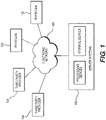
- FIG. 1 depicts a block diagram of an exemplary system and network for predicting coronary plaque vulnerability from patient-specific anatomic image data.
- FIG. 1 depicts a plurality of physicians 102 and third party providers 104, any of whom may be connected to an electronic network 100, such as the Internet, through one or more computers, servers, and/or handheld mobile devices.
- Physicians 102 and/or third party providers 104 may create or otherwise obtain images of one or more patients' cardiac and/or vascular systems.
- the physicians 102 and/or third party providers 104 may also obtain any combination of patient-specific information, such as age, medical history, blood pressure, blood viscosity, etc.
- Physicians 102 and/or third party providers 104 may transmit the cardiac/vascular images and/or patient-specific information to server systems 106 over the electronic network 100.
- Server systems 106 may include storage devices for storing images and data received from physicians 102 and/or third party providers 104.
- Server systems 106 may also include processing devices for processing images and data stored in the storage devices.
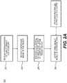
- FIG. 2A is a block diagram of an exemplary method 200 for creating a patient-specific model from multiple images, according to an exemplary embodiment of the present disclosure.
- patient images that are obtained via various imaging techniques or at different points in time may be compiled to create a final model.
- the final model created may depict different parts of anatomy or various aspects of the anatomy, depending on the input images.
- Some embodiments of the method may include first obtaining a model of the target anatomy object, to which patient images may be mapped. Other embodiments of the method may further include reference images that may serve as a point of comparison for such mapping.
- Method 200 may be performed by server systems 106, based on information, images, and data received from physicians 102 and/or third party providers 104 over electronic network 100. The method of FIG.
- the representation 2A may include receiving a representation of a target object for modeling (step 202).
- the representation may be stored on an electronic storage device (e.g., hard drive, RAM, network drive, etc.).
- the representation may include an object localization model (e.g., a boundary model or volumetric model).
- the representation may also include, but is not limited to, an appearance model or shape model.
- the representation may be determined by a set of parameters estimated from the images.
- the object localization model may include a resultant object model based on the estimated parameters. For instance, the resultant object model may be comprised of a fully determined set of parameters.
- An exemplary set of parameters to determine an object model is the assignment of a binary indicator value to every pixel, the assignment of a probability or level set value to every pixel.
- Another set of parameters that may be used to represent an object model is a set of 3D coordinates and triangles to represent the triangulated surface of a 3D object.
- Step 204 of method 200 may involve receiving a reference image that depicts the target object.
- the reference image may be 2-D, 3-D, or 4-D, and the image may be stored in an electronic storage device.
- the reference image may be directly associated with the target object.
- the reference image may be selected based on inferences from the resultant object model.
- step 206 may involve receiving a collection of two or more 2-D, 3-D, or 4-D images that depict at least part of the target object.
- this collection of images may be specific to the patient.
- the images are stored and/or transferred via an electronic storage device.
- image refers to an image regardless of dimension.
- each element making up the image may be referred to as a "pixel” or "voxel,” regardless of the image size or resolution.
- each element of a 2-D image may be a pixel, regardless of the image dimensions.
- each element of a 3-D image or volumetric model may be regarded as a "voxel,” for images or models of any size or resolution.
- Step 208 of method 200 may include processing the representation from step 202, the reference image from step 204, and image collection of step 206 to output final object model parameters.
- step 208 may include outputting the parameters to an electronic storage device and/or performing the processing using a computational device (including but not limited to a computer, laptop, DSP, cloud server, tablet, smart phone, etc.).
- a computational device including but not limited to a computer, laptop, DSP, cloud server, tablet, smart phone, etc.
- method 220 of FIG. 2B may be an exemplary method for performing the processing of step 208.
- method 200 may employ method 220 to process gathered information and produce the final object parameters output in step 208.
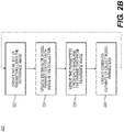
- FIG. 2B is a block diagram of an exemplary method 220 for processing various images and/or sets of images to produce final object parameters, according to an exemplary embodiment of the present disclosure.
- Method 220 may also be performed by server systems 106, based on information, images, and data received from physicians 102 and/or third party providers 104 over electronic network 100.
- the method of FIG. 2B may include creating an initial set of parameters for the object model using the reference image (step 222).
- initial parameters may be determined by using an image segmentation technique.
- step 222 may include defining a set of parameters of interest for the object model, and then determining the parameters for the reference image. Alternately, step 222 may include determining a set of parameters available from the reference image. Step 222 may further include determining values of each of the parameters. In some cases, this set of parameters may serve as initialized parameters.
- Step 224 may include creating an estimate of some of the object model parameters for each image in the collection (received in step 206).
- the initialized parameters from step 222 may or may not be used to create the estimate. For example, estimates may be made of more object parameters than are included in the set of initialized parameters. Alternately, estimates may be made for only a subset of the initialized parameters or the full set of initialized parameters.
- step 226 may include updating or merging the parameters from each image in the collection with parameters and parameter values estimated from the reference image.
- image parameters from a first set of image parameters may be updated based on image parameters obtained from a second set of images.
- image parameters may be merged by combining and/or averaging corresponding image parameters obtained from multiple sets of images. Updating parameters may include merging, combining, averaging parameters.
- updating parameters may include, both changes or verification of existing parameters, as well as generating new parameters.
- step 226 may lead to step 228 of creating a combined estimate of the object.
- steps 222-228 may be repeated until the object model parameters converge.
- the object model parameters may converge into final object parameters. These final object parameters may serve as the output at step 208 of method 200, where final object parameters are output to an electronic storage device.
- Method 200 may be used to produce various models, depending on the patient images used in step 206 and the processing of those images in method 220.
- the following disclosure presents several exemplary embodiments of, or alternatives to method 200.
- FIGs. 3A-3C are block diagrams of exemplary methods for obtaining volumetric models of probabilities that given voxels belong to a patient lumen
- FIGs. 4A-4C are block diagrams of exemplary methods for producing final object models of patient centerline trees and lumen diameters
- FIG. 5 is a block diagram of an exemplary method to generate a final model of cell locations and diameters. All of the images and final object models discussed may be stored in and/or output to electronic storage devices.
- FIGs. 3A-3C depict methods for coronary vessel modeling, where a final volumetric model includes probabilities that each voxel belongs to a patient coronary vessel lumen.
- a final volumetric model includes probabilities that each voxel belongs to a patient coronary vessel lumen.
- different imaging techniques may produce patient images that each portray a coronary vessel lumen in some capacity.
- Each element (e.g., voxel) of each image may carry some probability that it is part of a vessel. Forming a composite of the images may therefore produce an accurate model of a patient coronary vessel lumen.
- the model may further include an assessment of the model's accuracy at any point in the model.
- FIG. 3A is an exemplary method of estimating the probabilities using CTA reconstructions
- FIG. 3B is an exemplary method of modeling using cardiac CTA images at different points in time
- FIG. 3C models the coronary vessel from one or more cardiac CTA images and MR images.
- FIG. 3A is a block diagram of an exemplary method 300 for obtaining volumetric models of probabilities based on CTA reconstructions.
- coronary vessels may be segmented using multiple cCTA images that represent multiple reconstructions.
- a parameterized representation of a target object may be received and stored on an electric storage device (e.g., hard drive, RAM, network drive, etc.) (step 301).
- the target object for this instance may be the coronary vessel lumen.
- the representation for step 301 may be a volumetric model of a patient's coronary vessel lumen, where each voxel represents the probability that the voxel belongs to the patient's coronary vessel lumen.
- Probabilities may or may not be displayed.
- probabilities may be displayed by showing respective probabilities of each voxel belonging to the patient's coronary vessel lumen by displaying a high probability as a high image intensity and a low probability as a low image intensity.
- Step 303 may involve receiving multiple 3-D images from a cardiac CT scanner, where each image represents different reconstructions of the cCTA image for the patient.
- Reconstructions may include, for example, images with different kernels for filtered backprojection and/or iterative reconstruction methods.
- Employing multiple reconstructions is useful in that each image reconstruction technique has different advantages and disadvantages for different types of image features.
- Each image reconstruction technique may be better for some types of image features and worse at others (e.g., blooming, streaking, noise, etc.). Using the best aspects of each reconstruction may help achieve a more precise object geometry.
- Step 305 may involve determining the probability that each voxel belongs to the patient's coronary vessel lumen.
- the probability may be determined by performing a segmentation of the coronary vessel lumen in each image.
- any known technique for performing segmentation to obtain voxel probabilities may be used, such as random walker algorithms or machine learning algorithms that map voxel intensities and their neighbors to probabilities.
- the segmentation may be performed using any existing technique, and the segmentation may be performed for the coronary vessel lumen independently with respect to each image.
- segmentation may be performed automatically by a computer system either based on user inputs or without user inputs. For instance, in an exemplary embodiment, the user may provide inputs to the computer system in order to generate a first initial model.
- the computer system may display to the user a 3-D image or slices thereof produced from the CCTA data.
- the 3-D image may include portions of varying intensity of lightness. For example, lighter areas may indicate the lumens of the aorta, the main coronary arteries, and/or the branches. Darker areas may indicate the myocardium and other tissue of the patient's heart.
- Step 307 may involve averaging the probabilities (from step 305) across the images to create a combined estimate of the volumetric model of the probability of each voxel belonging to the patient lumen.
- steps 305 and 307 may be performed using a computer.
- the final, averaged volumetric model of the probabilities may be output (step 309), for example, to an electronic storage device.
- the averaged volumetric model of the probabilities may be output in the form of a color overlay showing the boundary of a level set on the probabilities, or as a set of raw probabilities.
- FIG. 3B is a block diagram of an exemplary method 320 for obtaining volumetric models of probabilities based on CTA images obtained at different points in time.
- step 321 involves obtaining a parameterized representation of a target object (e.g., a coronary vessel lumen).
- the representation may be a volumetric model of a patient's coronary vessel lumen in which each voxel represents the probability that the voxel belongs to the patient's coronary vessel lumen.
- step 323 may involve receiving multiple 3-D images from a cardiac CT scanner where each image represents a different reconstruction of the cCTA image for a patient.
- the images may represent acquisitions from a single patient, at multiple points in time (e.g., time points within the cardiac cycle or an initial acquisition and follow-up scan). Using images at multiple time points means that each image may contain independent information that may contain less artifact or better quality in different regions of the image. Method 320 may include using the best aspects of each reconstruction to achieve a final model of precise object geometry.
- the images for step 323 may be stored in an electronic storage device. For example, a storage device may determine a new image acquisition and update a final volumetric model by taking into account the new acquisition.
- Step 325a may reflect step 305 in determining the probability that each voxel belongs to the patient's coronary vessel lumen.
- step 325a may include finding the probability by performing a segmentation of the coronary vessel lumen independently in each image (using any existing technique).
- step 325b may involve choosing a reference image.
- the reference image may be arbitrary among the acquired images, retrieved from a reference image repository, selected intentionally from a set of acquired images, etc.
- 3-D registration may be used to register each image to the reference image (step 325c).
- steps 325a-325c may be analogous to steps 345a-345c of FIG. 3C .
- Step 327 may involve creating a combined estimate of the volumetric model by averaging probabilities across images.
- the images for step 327 may include patient images and the reference image.
- the image registration may be used to map each voxel to another voxel, meaning mapping a location in each image to a location (or locations) in the reference image and/or other images.
- the mapping may be performed using any method such that voxels in two images may be identified as being representations of the same part of the target object (e.g., coronary vessel lumen). Since the voxels correspond to the same part, the voxel probabilities may be combined.
- step 329 may include outputting the final volumetric model of the probabilities to an electronic storage device.
- FIG. 3C is a block diagram of an exemplary method 340 for obtaining volumetric models of probabilities based on a plurality of cCTA images that represent the coronary tree and a plurality of cardiac magnetic resonance (MR) images that also depict the coronary tree.
- Step 341 involves receiving a parameterized representation of a coronary vessel lumen stored on an electronic storage device, similar to steps 301 and 321.
- the representation may be a volumetric model of the patient's coronary vessel lumen, in which each voxel represents the probability that the voxel belongs to the patient's coronary vessel lumen.
- step 343 may further include receiving one or more 3-D images from a cardiac MR scan of a patient.
- CT and MR cardiac images may be acquired to obtain different cardiac information available from each modality (e.g., fine detail with CT and viability with MR).
- MR imaging may exhibit fewer blooming artifacts near calcium than CT images exhibit, so MR images may be more useful in some cases for examining the geometry of calcified lesions.
- Both the CT scan(s) and MR scan(s) may be stored in an electronic storage device.
- steps 345a-345c may be similar to steps 325a-325c, as applied to a context involving MR images. These steps may all be performed using a computer.
- Step 345a like steps 305 and 325a, may involve segmentation that determines probability associated with each voxel that the voxel belongs to the patient's coronary vessel lumen.
- step 345b may involve choosing an arbitrary image or an image with the greatest spatial resolution as a reference image. Thus, the reference image may, in some cases, have the smallest voxel size.
- Step 345c may involve using 3-D image registration to register each image to the reference image from step 345b.
- step 345c may include using 3-D image registration to register each voxel probability in each image to each respective voxel probability in the reference image.
- Steps 345c and 347 may involve creating a combined estimate of a volumetric model by using the image registration to map each voxel probability to a corresponding voxel probability of the reference image. Again, in one embodiment, the mapping may create a merged (e.g., averaged) voxel probability.
- Step 349 analogous to steps 309 and 329, may involve outputting the averaged, final volumetric model of the probabilities to an electronic storage device.
- FIGs. 4A-4C depict methods for coronary vessel modeling, where the final model may be an object model of the centerline tree and lumen diameters of the coronary vessel.
- FIG. 4A represents vessel modeling from a cardiac CTA image and an intravascular ultrasound (IVUS) and/or intravascular optical coherence tomography (OCT) image
- FIGs. 4B and 4C are two embodiments of a method of coronary vessel modeling from a cardiac CTA image and an angiography image.
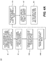
- FIG. 4A is a block diagram of an exemplary method 400 for coronary vessel modeling from a cardiac CTA image and an IVUS/OCT image.
- a parameterized representation of the target object e.g., a coronary vessel lumen
- the representation may be a model of a patient's coronary vessel lumen in which each vessel is represented by a centerline and the lumen boundary is represented by a lumen diameter associated with each centerline location.
- Step 403 may involve receiving one or more 3-D images from a cardiac CT scan and one or more intravascular images of the same patient.
- the coronary vessels may be segmented using one or more cCTA images that represent the entire coronary tree and one or more IVUS or OCT images of at least a portion of the coronary tree.
- intravascular images may be taken to refer to the IVUS and/or OCT images.
- Cardiac CTA and intravascular cardiac images may be acquired due to different cardiac information generated by each modality (e.g., complete 3-D vessel tree from CT and high-resolution vessel geometry from intravascular imagery).
- intravascular imaging may exhibit fewer blooming artifacts near calcium than are exhibited by CT. As a result, intravascular imaging may be especially useful for the purpose of examining the geometry of calcified lesions.
- a segmentation of the coronary vessel lumen may be performed independently in each image to create either a complete centerline tree (e.g., for the coronary CT images) or a part of the centerline tree (e.g., for intravascular images). This segmentation may determine the diameter of the coronary vessel lumen at each location of the centerline.
- Step 405b may involve choosing an arbitrary cCTA image as the reference image, and step 405c may involve using registration to register each object model or part of an object model to the object model obtained from the reference image.
- each object model may be comprised of one or more centerlines and/or one or more lumen diameters.
- a combined estimate of the object model may be created by averaging the lumen diameter at each centerline location with an estimate from each source (e.g., as determined from step 405a). All the steps of method 400 may be performed using a computer, especially steps 405a-407. Lastly, a final, averaged object model of the centerline tree and lumen diameters may be output (step 409).
- FIG. 4B is a block diagram of an exemplary method 420 for coronary vessel modeling from a cardiac CTA image and an angiography image.
- step 421 may include receiving a parameterized representation of a coronary vessel lumen as a target object, where the representation may be a model of the lumen.
- each vessel may be represented by a centerline and the lumen boundary may be represented by a lumen diameter associated with each centerline location.
- Step 423 may involve receiving one or more 3-D images from a cardiac CT scan and one or more angiography images of the same patient.
- coronary vessels may be segmented using one or more cCTA images that represent the entire coronary tree, but in contrast to method 400, at least a portion of the coronary tree may be segmented using one or more 2-D angiography images, rather than (or in addition to) IVUS and/or OCT images.
- Cardiac CTA and angiography images may be acquired due to different cardiac information generated by each modality (e.g., complete 3-D vessel tree from CT and high-resolution vessel geometry from the angiography).
- angiography imaging may exhibit fewer blooming artifacts near calcium than exhibited by CT, making it useful for examining the geometry of calcified lesions.
- steps 425a-425c may be analogous to steps 445a-445c of FIG. 4C ; and steps 425a-427 and steps 445a-447 may all be performed using a computer.
- Step 425a may involve performing segmentation of the coronary vessel lumen independently in each image to create a complete centerline tree (e.g., for the coronary CT images) or a part of the centerline tree (e.g., for the angiography images). The segmentation may determine the diameter of the coronary vessel lumen at each point of the centerline.
- an arbitrary cCTA image may be chosen as a reference image (step 425b) and registration may be used to register each object model or part of an object model to the object model obtained from the reference image.
- Each object model may be comprised of one or more centerline(s) and one or more lumen diameter(s). If viewing angles are available for the angiography images, the information from that analysis may be taken into account when registering the models (step 425c).
- Step 427 may involve creating a combined estimate of the object model by averaging lumen diameter(s) at each centerline location with an estimate of the diameter from each source (e.g., as given by step 425a).
- Step 429 may include outputting a final, averaged object model of centerline tree and lumen diameters.
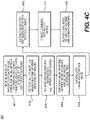
- FIG. 4C is a block diagram of an exemplary method 440, also for coronary vessel modeling from a cardiac CTA image and an angiography image.
- Method 440 may be used as an alternative to method 420.
- method 440 may begin with obtaining a parameterized representation that is a model of a patient's coronary vessel lumen, in which each lumen is represented by a centerline, and the lumen boundary may be represented by a lumen diameter associated with each centerline location (step 441).
- Step 443a may involve receiving a 3-D image from a cardiac CT scan and one or more angiography images of the same patient with viewing angles for each angiography image.
- a further step 443b may involve receiving additional patient-specific information, such as, for example, an upper and/or lower bound on total vascular volume.
- Step 445a may include performing a segmentation of the coronary vessel lumen to create a complete centerline tree (e.g., for the coronary CT images) or part of the centerline tree (e.g., for the angiography images), where the segmentation may determine the diameter of the coronary vessel lumen at each location of the centerline.
- step 445b may choose the cCTA image as the reference image.
- step 445c may involve evaluating whether all the 2-D projections of the geometric model onto the 2-D angiography spaces match respective 2-D segmentations and constraints of the additional patient-specific information.
- the matching may be done in a Bayesian framework if the projections are described as probability density functions. If a match is achieved, a geometric representation may be extracted from the cCTA image (step 447).
- Step 449 may include outputting a final object model of the centerline tree and lumen diameters.
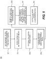
- FIG. 5 is a block diagram of an exemplary method 500 for modeling anatomy from multiple optical (e.g., histopathological) images.
- optical images may be obtained for various types of tissue.
- Tissue samples may be from surgery, biopsy, or autopsy.
- Histopathological examination of tissue samples may include processing multiple optical images of the tissue in order to create a final model of cells of the tissue sample. Such information may offer insight into diseases affecting the tissue.
- the method may begin with obtaining a parameterized representation of target objects (step 501).
- the target objects may be a set of cell locations in a tissue sample.
- step 501 may include retrieving a model of cell locations and a diameter for each location.
- Step 503 may involve receiving two or more 2-D or 3-D histopathology images of the same tissue sample.
- Cell locations of a tissue sample may be computed from multiple 2-D histopathology optical images. Multiple images might be acquired to provide a hyper-precise localization of all cells in the tissue sample.
- Step 505a may then include performing a localization of all cells in an image to create a center location and diameter estimate for each cell.
- an arbitrary histopathology image may be chosen as the reference image (step 505b), and registration may be used to register each cells model to the cells model obtained from the reference image (step 505c).
- each cells model may comprise a center location and/or diameter for each cell in a field of view associated with the tissue sample.
- step 507 may include averaging center locations and diameter estimates for each cell from all cell models. Based on the averaging, step 507 may further involve creating a combined estimate of the cells model. Again, an output of the final, averaged model of cell locations and/or diameters may be made (step 509).
- modeling may be improved using multiple images, whether the variations are images acquired from reconstructions, various imaging modalities, or acquisitions at different points in time.
- Creating models by aggregating multiple images permits the combination of benefits of different imaging modalities models, reduces errors or imperfections in individual image acquisitions, and strengthens the credibility of the final model.
- the technique of modeling using multiple images may be applied to model any target object, anatomy of interest, or information associated with that target object and/or anatomy or interest.
- a computer-implemented method of modeling at least a portion of a patient's anatomy, using a computer system comprises:
- the one or more first images may include one or more computed tomography (CT) scans obtained using a first reconstruction method
- the one or more second images may include one or more CT scans obtained using a second reconstruction method.
- CT computed tomography
- the one or more first images may include one or more CT scans obtained at a first time
- the one or more second images may include one or more CT scans obtained at a second time that is different from the first time.
- the one or more first images may include one or more CT scans and the one or more second images may include one or more magnetic resonance (MR) images.
- MR magnetic resonance
- the representation of the target anatomical object may include one or more of a boundary model, volume model, appearance model, and a shape model.
- the representation of the target anatomical object may include a model of a patient coronary vessel lumen, the model including a plurality of voxels representing a probability that each of the plurality of voxels belongs to the patient's coronary vessel lumen.
- the updating of the one or more first anatomical parameters with the one or more second anatomical parameters may include averaging a probability that a voxel of a first image belongs to the patient's coronary vessel lumen with a probability that a voxel of a second image belongs to the patient's coronary vessel lumen.
- the updating of the one or more first anatomical parameters with the one or more second anatomical parameters may include combining the one or more first anatomical parameters with the one or more second anatomical parameters.
- the determining of the one or more first or second anatomical parameters may include performing segmentation of at least one of the first images or at least one of the second images to determine a probability that a portion of the image represents a portion of the target anatomical object.
- the updating of the one or more first anatomical parameters with the one or more second anatomical parameters may include averaging a probability that a portion of a first image represents a portion of the target anatomical object with a probability that a portion of a second image represents the portion of the target anatomical object.
- the method described in paragraph [061], may further comprise: designating one of the first images or second images as a reference image;
- the method described in paragraph [062], may further comprise:
- a system of modeling at least a portion of a patient's anatomy comprises:
- the one or more first images may include one or more computed tomography (CT) scans obtained using a first reconstruction method
- the one or more second images may include one or more CT scans obtained using a second reconstruction method.
- CT computed tomography
- the one or more first images may include one or more CT scans obtained at a first time
- the one or more second images may include one or more CT scans obtained at a second time that is different from the first time.
- the one or more first images may include one or more CT scans and the one or more second images may include one or more magnetic resonance (MR) images.
- MR magnetic resonance
- a non-transitory computer readable medium for use on a computer system contains computer-executable programming instructions for modeling at least a portion of a patient's anatomy according to a method comprising:
- the one or more first images may include one or more computed tomography (CT) scans obtained using a first reconstruction method
- the one or more second images may include one or more CT scans obtained using a second reconstruction method.
- CT computed tomography
- the one or more first images may include one or more CT scans obtained at a first time
- the one or more second images may include one or more CT scans obtained at a second time that is different from the first time.
- the one or more first images may include one or more CT scans and the one or more second images may include one or more magnetic resonance (MR) images.
- MR magnetic resonance
Landscapes
- Engineering & Computer Science (AREA)
- Theoretical Computer Science (AREA)
- General Physics & Mathematics (AREA)
- Physics & Mathematics (AREA)
- Computer Vision & Pattern Recognition (AREA)
- Medical Informatics (AREA)
- Quality & Reliability (AREA)
- Radiology & Medical Imaging (AREA)
- Nuclear Medicine, Radiotherapy & Molecular Imaging (AREA)
- Health & Medical Sciences (AREA)
- General Health & Medical Sciences (AREA)
- Computer Graphics (AREA)
- Apparatus For Radiation Diagnosis (AREA)
- Magnetic Resonance Imaging Apparatus (AREA)
- Nuclear Medicine (AREA)
Applications Claiming Priority (3)
| Application Number | Priority Date | Filing Date | Title |
|---|---|---|---|
| US14/254,491 US9058692B1 (en) | 2014-04-16 | 2014-04-16 | Systems and methods for image-based object modeling using multiple image acquisitions or reconstructions |
| PCT/US2015/025691 WO2015160763A1 (en) | 2014-04-16 | 2015-04-14 | Systems and methods for image-based object modeling using multiple image acquisitions or reconstructions |
| EP15720834.9A EP3132419B1 (en) | 2014-04-16 | 2015-04-14 | Systems and methods for image-based object modeling using multiple image acquisitions or reconstructions |
Related Parent Applications (1)
| Application Number | Title | Priority Date | Filing Date |
|---|---|---|---|
| EP15720834.9A Division EP3132419B1 (en) | 2014-04-16 | 2015-04-14 | Systems and methods for image-based object modeling using multiple image acquisitions or reconstructions |
Publications (1)
| Publication Number | Publication Date |
|---|---|
| EP4002269A1 true EP4002269A1 (en) | 2022-05-25 |
Family
ID=53053088
Family Applications (2)
| Application Number | Title | Priority Date | Filing Date |
|---|---|---|---|
| EP15720834.9A Active EP3132419B1 (en) | 2014-04-16 | 2015-04-14 | Systems and methods for image-based object modeling using multiple image acquisitions or reconstructions |
| EP21217448.6A Pending EP4002269A1 (en) | 2014-04-16 | 2015-04-14 | Systems and methods for image-based object modeling using multiple image acquisitions or reconstructions |
Family Applications Before (1)
| Application Number | Title | Priority Date | Filing Date |
|---|---|---|---|
| EP15720834.9A Active EP3132419B1 (en) | 2014-04-16 | 2015-04-14 | Systems and methods for image-based object modeling using multiple image acquisitions or reconstructions |
Country Status (4)
| Country | Link |
|---|---|
| US (6) | US9058692B1 (zh) |
| EP (2) | EP3132419B1 (zh) |
| JP (2) | JP6409073B2 (zh) |
| WO (1) | WO2015160763A1 (zh) |
Families Citing this family (30)
| Publication number | Priority date | Publication date | Assignee | Title |
|---|---|---|---|---|
| EP2994904A4 (en) | 2013-05-10 | 2017-01-18 | Stenomics, Inc. | Modeling and simulation system for optimizing prosthetic heart valve treatment |
| US9092743B2 (en) | 2013-10-23 | 2015-07-28 | Stenomics, Inc. | Machine learning system for assessing heart valves and surrounding cardiovascular tracts |
| US9514530B2 (en) | 2014-04-16 | 2016-12-06 | Heartflow, Inc. | Systems and methods for image-based object modeling using multiple image acquisitions or reconstructions |
| US10176408B2 (en) | 2015-08-14 | 2019-01-08 | Elucid Bioimaging Inc. | Systems and methods for analyzing pathologies utilizing quantitative imaging |
| US11676359B2 (en) | 2015-08-14 | 2023-06-13 | Elucid Bioimaging Inc. | Non-invasive quantitative imaging biomarkers of atherosclerotic plaque biology |
| US11113812B2 (en) | 2015-08-14 | 2021-09-07 | Elucid Bioimaging Inc. | Quantitative imaging for detecting vulnerable plaque |
| US11071501B2 (en) | 2015-08-14 | 2021-07-27 | Elucid Bioiwaging Inc. | Quantitative imaging for determining time to adverse event (TTE) |
| US11087459B2 (en) | 2015-08-14 | 2021-08-10 | Elucid Bioimaging Inc. | Quantitative imaging for fractional flow reserve (FFR) |
| US11094058B2 (en) | 2015-08-14 | 2021-08-17 | Elucid Bioimaging Inc. | Systems and method for computer-aided phenotyping (CAP) using radiologic images |
| EP3374895A1 (en) | 2015-11-10 | 2018-09-19 | HeartFlow, Inc. | Systems and methods for anatomical modeling using information from a procedure |
| US10354378B2 (en) | 2016-04-06 | 2019-07-16 | University Of Washington | Systems and methods for quantitative assessment of microvasculature using optical coherence tomography angiography |
| WO2017199245A1 (en) | 2016-05-16 | 2017-11-23 | Cathworks Ltd. | System for vascular assessment |
| WO2017199246A1 (en) | 2016-05-16 | 2017-11-23 | Cathworks Ltd. | Vascular selection from images |
| US10398382B2 (en) * | 2016-11-03 | 2019-09-03 | Siemens Medical Solutions Usa, Inc. | Respiratory motion estimation in projection domain in nuclear medical imaging |
| EP3559903B1 (en) * | 2016-12-23 | 2023-03-22 | HeartFlow, Inc. | Machine learning of anatomical model parameters |
| WO2019071249A1 (en) | 2017-10-06 | 2019-04-11 | Emory University | METHODS AND SYSTEMS FOR DETERMINING HEMODYNAMIC INFORMATION FOR ONE OR MORE ARTERIAL SEGMENTS |
| WO2019075376A1 (en) | 2017-10-13 | 2019-04-18 | The Research Foundation For The State University Of New York | OPTICAL DOPPLER TOMOGRAPHY WITH WAVELENGTH DIVISION MULTIPLEXING SCANNED SOURCE |
| EP3471054B1 (en) * | 2017-10-16 | 2022-02-09 | Siemens Healthcare GmbH | Method for determining at least one object feature of an object |
| US11871995B2 (en) | 2017-12-18 | 2024-01-16 | Hemolens Diagnostics Sp. Z O.O. | Patient-specific modeling of hemodynamic parameters in coronary arteries |
| US10813612B2 (en) | 2019-01-25 | 2020-10-27 | Cleerly, Inc. | Systems and method of characterizing high risk plaques |
| JP2022543330A (ja) | 2019-08-05 | 2022-10-12 | エルシド バイオイメージング インコーポレイテッド | 形態学的および血管周囲疾患の複合評価 |
| CN110853021B (zh) * | 2019-11-13 | 2020-11-24 | 江苏迪赛特医疗科技有限公司 | 一种病理鳞状上皮细胞的检测分类模型的构建 |
| US11963740B2 (en) | 2019-12-05 | 2024-04-23 | Canon U.S.A., Inc. | Lumen, stent, and/or artifact detection in one or more images, such as in optical coherence tomography images |
| WO2021141921A1 (en) | 2020-01-07 | 2021-07-15 | Cleerly, Inc. | Systems, methods, and devices for medical image analysis, diagnosis, risk stratification, decision making and/or disease tracking |
| US20220392065A1 (en) | 2020-01-07 | 2022-12-08 | Cleerly, Inc. | Systems, methods, and devices for medical image analysis, diagnosis, risk stratification, decision making and/or disease tracking |
| US11969280B2 (en) | 2020-01-07 | 2024-04-30 | Cleerly, Inc. | Systems, methods, and devices for medical image analysis, diagnosis, risk stratification, decision making and/or disease tracking |
| WO2022032455A1 (en) * | 2020-08-10 | 2022-02-17 | Shanghai United Imaging Healthcare Co., Ltd. | Imaging systems and methods |
| EP4002288A1 (en) * | 2020-11-12 | 2022-05-25 | Koninklijke Philips N.V. | Methods and systems for rendering representations of subject vasculature |
| EP4084011A1 (en) * | 2021-04-30 | 2022-11-02 | Siemens Healthcare GmbH | Computer-implemented method and evaluation system for evaluating at least one image data set of an imaging region of a patient, computer program and electronically readable storage medium |
| US20230289963A1 (en) | 2022-03-10 | 2023-09-14 | Cleerly, Inc. | Systems, devices, and methods for non-invasive image-based plaque analysis and risk determination |
Citations (1)
| Publication number | Priority date | Publication date | Assignee | Title |
|---|---|---|---|---|
| US20070019846A1 (en) * | 2003-08-25 | 2007-01-25 | Elizabeth Bullitt | Systems, methods, and computer program products for analysis of vessel attributes for diagnosis, disease staging, and surfical planning |
Family Cites Families (58)
| Publication number | Priority date | Publication date | Assignee | Title |
|---|---|---|---|---|
| TWI221406B (en) * | 2001-07-30 | 2004-10-01 | Epix Medical Inc | Systems and methods for targeted magnetic resonance imaging of the vascular system |
| EP1662974A4 (en) * | 2003-08-21 | 2009-06-03 | Ischem Corp | AUTOMATED SYSTEMS AND SYSTEMS FOR VASCULAR PLATE DETECTION AND ANALYSIS |
| US8010175B2 (en) * | 2004-05-05 | 2011-08-30 | Siemens Medical Solutions Usa, Inc. | Patient-specific coronary territory mapping |
| US20060036167A1 (en) | 2004-07-03 | 2006-02-16 | Shina Systems Ltd. | Vascular image processing |
| WO2006036842A2 (en) * | 2004-09-24 | 2006-04-06 | The University Of North Carolina At Chapel Hill | Methods, systems, and computer program products for hierarchical registration between a blood vessel and tissue surface model for a subject and blood vessel and tissue surface image for the subject |
| US8352013B2 (en) * | 2005-01-18 | 2013-01-08 | Siemens Medical Solutions Usa, Inc. | Method and system for motion compensation in magnetic resonance (MR) imaging |
| US8285011B2 (en) | 2005-06-02 | 2012-10-09 | M2S | Anatomical visualization and measurement system |
| WO2007002685A2 (en) * | 2005-06-24 | 2007-01-04 | Volcano Corporation | Co-registration of graphical image data representing three-dimensional vascular features |
| US8406851B2 (en) * | 2005-08-11 | 2013-03-26 | Accuray Inc. | Patient tracking using a virtual image |
| CA2619308A1 (en) * | 2005-08-17 | 2007-02-22 | Koninklijke Philips Electronics, N.V. | Method and apparatus for automatic 4d coronary modeling and motion vector field estimation |
| US20080033302A1 (en) * | 2006-04-21 | 2008-02-07 | Siemens Corporate Research, Inc. | System and method for semi-automatic aortic aneurysm analysis |
| US8923577B2 (en) * | 2006-09-28 | 2014-12-30 | General Electric Company | Method and system for identifying regions in an image |
| WO2010058398A2 (en) * | 2007-03-08 | 2010-05-27 | Sync-Rx, Ltd. | Image processing and tool actuation for medical procedures |
| WO2008110013A1 (en) * | 2007-03-15 | 2008-09-18 | Centre Hospitalier De L'universite De Montreal | Image segmentation |
| JP2011504115A (ja) * | 2007-10-18 | 2011-02-03 | ザ ユニバーシティ オブ ノース カロライナ アット チャペル ヒル | 1つの画像データからの解剖学的構造を含む対象物のモデルの領域を、診断的又は治療的介入に用いられる画像にマッピングするための方法、そのシステム及びコンピューター読み取り可能な媒体 |
| WO2009049681A1 (en) * | 2007-10-19 | 2009-04-23 | Vascops | Automatic geometrical and mechanical analyzing method and system for tubular structures |
| US8218845B2 (en) * | 2007-12-12 | 2012-07-10 | Siemens Aktiengesellschaft | Dynamic pulmonary trunk modeling in computed tomography and magnetic resonance imaging based on the detection of bounding boxes, anatomical landmarks, and ribs of a pulmonary artery |
| JP5241357B2 (ja) * | 2008-07-11 | 2013-07-17 | 三菱プレシジョン株式会社 | 生体データモデル作成方法及びその装置 |
| JP5009391B2 (ja) * | 2009-07-03 | 2012-08-22 | 富士フイルム株式会社 | 診断支援装置、診断支援プログラムおよび診断支援方法 |
| EP2465094B1 (en) * | 2009-08-12 | 2016-01-06 | Koninklijke Philips N.V. | Generating object data |
| US8224640B2 (en) * | 2009-09-08 | 2012-07-17 | Siemens Aktiengesellschaft | Method and system for computational modeling of the aorta and heart |
| US8478012B2 (en) * | 2009-09-14 | 2013-07-02 | General Electric Company | Methods, apparatus and articles of manufacture to process cardiac images to detect heart motion abnormalities |
| GB2478329B (en) * | 2010-03-03 | 2015-03-04 | Samsung Electronics Co Ltd | Medical image processing |
| EP2545527B1 (en) | 2010-03-11 | 2014-07-02 | Koninklijke Philips N.V. | Probabilistic refinement of model-based segmentation |
| US8315812B2 (en) | 2010-08-12 | 2012-11-20 | Heartflow, Inc. | Method and system for patient-specific modeling of blood flow |
| JP4937397B2 (ja) * | 2010-10-25 | 2012-05-23 | 富士フイルム株式会社 | 医用画像診断支援装置および方法、並びにプログラム |
| DE102011076233B4 (de) * | 2011-02-09 | 2013-04-18 | Siemens Aktiengesellschaft | Verfahren und Computersystem zur Erkennung einer statistisch relevanten Normvariante der Gefaßstruktur eines Patienten mit Hilfe tomographischer Bilddatensatze |
| WO2012112929A2 (en) * | 2011-02-17 | 2012-08-23 | The Johns Hopkins University | Methods and systems for registration of radiological images |
| US8761474B2 (en) * | 2011-07-25 | 2014-06-24 | Siemens Aktiengesellschaft | Method for vascular flow pattern analysis |
| US8948487B2 (en) * | 2011-09-28 | 2015-02-03 | Siemens Aktiengesellschaft | Non-rigid 2D/3D registration of coronary artery models with live fluoroscopy images |
| JP5784751B2 (ja) * | 2011-12-08 | 2015-09-24 | オリンパス株式会社 | 画像処理装置、画像処理装置の作動方法、及び画像処理プログラム |
| US9842194B2 (en) * | 2012-02-13 | 2017-12-12 | Koninklijke Philips N.V. | Simplified method for robust estimation of parameter values |
| US9384546B2 (en) * | 2012-02-22 | 2016-07-05 | Siemens Aktiengesellschaft | Method and system for pericardium based model fusion of pre-operative and intra-operative image data for cardiac interventions |
| US20150185298A1 (en) * | 2012-06-05 | 2015-07-02 | The University Of Queensland | Method of estimating specific absorption rate |
| US8958618B2 (en) * | 2012-06-28 | 2015-02-17 | Kabushiki Kaisha Toshiba | Method and system for identification of calcification in imaged blood vessels |
| US9277970B2 (en) * | 2012-07-19 | 2016-03-08 | Siemens Aktiengesellschaft | System and method for patient specific planning and guidance of ablative procedures for cardiac arrhythmias |
| JP5487264B2 (ja) * | 2012-09-07 | 2014-05-07 | 三菱プレシジョン株式会社 | 生体データモデル作成方法及びその装置 |
| WO2014037013A1 (en) * | 2012-09-07 | 2014-03-13 | Region Nordjylland, Aalborg Sygehus | System for detecting blood vessel structures in medical images |
| US9858387B2 (en) * | 2013-01-15 | 2018-01-02 | CathWorks, LTD. | Vascular flow assessment |
| US10210956B2 (en) * | 2012-10-24 | 2019-02-19 | Cathworks Ltd. | Diagnostically useful results in real time |
| US10595807B2 (en) * | 2012-10-24 | 2020-03-24 | Cathworks Ltd | Calculating a fractional flow reserve |
| US9036885B2 (en) * | 2012-10-28 | 2015-05-19 | Technion Research & Development Foundation Limited | Image reconstruction in computed tomography |
| JP2014100249A (ja) * | 2012-11-19 | 2014-06-05 | Toshiba Corp | 血管解析装置、医用画像診断装置、血管解析方法、及び血管解析プログラム |
| KR102106535B1 (ko) * | 2013-02-06 | 2020-05-06 | 삼성전자주식회사 | 일 호흡 주기에 따른 장기의 형상 및 위치의 변화를 나타내는 모델을 생성하는 방법, 장치 및 시스템. |
| US20140364739A1 (en) * | 2013-06-06 | 2014-12-11 | General Electric Company | Systems and methods for analyzing a vascular structure |
| US9463072B2 (en) * | 2013-08-09 | 2016-10-11 | Siemens Aktiengesellschaft | System and method for patient specific planning and guidance of electrophysiology interventions |
| WO2015058780A1 (en) * | 2013-10-25 | 2015-04-30 | Biontech Ag | Method and kit for determining whether a subject shows an immune response |
| EP3084723B1 (en) * | 2013-12-17 | 2021-04-28 | Koninklijke Philips N.V. | Spectral image data processing |
| CN105849773B (zh) * | 2013-12-17 | 2020-06-09 | 皇家飞利浦有限公司 | 解剖结构的基于模型的分割 |
| US10496729B2 (en) * | 2014-02-25 | 2019-12-03 | Siemens Healthcare Gmbh | Method and system for image-based estimation of multi-physics parameters and their uncertainty for patient-specific simulation of organ function |
| US9247920B2 (en) * | 2014-02-27 | 2016-02-02 | General Electric Company | System and method for performing bi-plane tomographic acquisitions |
| WO2015153832A1 (en) * | 2014-04-02 | 2015-10-08 | Siemens Aktiengesellschaft | System and method for characterization of electrical properties of the heart from medical images and body surface potentials |
| US9514530B2 (en) | 2014-04-16 | 2016-12-06 | Heartflow, Inc. | Systems and methods for image-based object modeling using multiple image acquisitions or reconstructions |
| US10127657B2 (en) * | 2014-05-20 | 2018-11-13 | Materialise N.V. | System and method for valve quantification |
| US9710025B2 (en) * | 2014-07-28 | 2017-07-18 | Group Dekko, Inc. | Desktop receptacle with utility front surface |
| US9972069B2 (en) * | 2014-10-06 | 2018-05-15 | Technion Research & Development Foundation Limited | System and method for measurement of myocardial mechanical function |
| US9349178B1 (en) * | 2014-11-24 | 2016-05-24 | Siemens Aktiengesellschaft | Synthetic data-driven hemodynamic determination in medical imaging |
| US10485510B2 (en) * | 2015-01-29 | 2019-11-26 | Siemens Healthcare Gmbh | Planning and guidance of electrophysiology therapies |
-
2014
- 2014-04-16 US US14/254,491 patent/US9058692B1/en active Active
-
2015
- 2015-03-18 US US14/662,009 patent/US9378580B2/en active Active
- 2015-04-14 EP EP15720834.9A patent/EP3132419B1/en active Active
- 2015-04-14 EP EP21217448.6A patent/EP4002269A1/en active Pending
- 2015-04-14 WO PCT/US2015/025691 patent/WO2015160763A1/en active Application Filing
- 2015-04-14 JP JP2016560645A patent/JP6409073B2/ja active Active
-
2016
- 2016-05-31 US US15/169,447 patent/US9965891B2/en active Active
-
2018
- 2018-04-02 US US15/943,266 patent/US10776988B2/en active Active
- 2018-09-21 JP JP2018177341A patent/JP6557767B2/ja active Active
-
2020
- 2020-08-14 US US16/993,322 patent/US11501485B2/en active Active
-
2022
- 2022-10-07 US US17/961,596 patent/US20230033594A1/en active Pending
Patent Citations (1)
| Publication number | Priority date | Publication date | Assignee | Title |
|---|---|---|---|---|
| US20070019846A1 (en) * | 2003-08-25 | 2007-01-25 | Elizabeth Bullitt | Systems, methods, and computer program products for analysis of vessel attributes for diagnosis, disease staging, and surfical planning |
Non-Patent Citations (3)
| Title |
|---|
| ADAMANTIOS ANDRIOTIS ET AL: "A new method of three-dimensional coronary artery reconstruction from X-ray angiography: Validation against a virtual phantom and multislice computed tomography", CATHETERIZATION AND CARDIOVASCULAR INTERVENTIONS, vol. 71, no. 1, 20 December 2007 (2007-12-20), US, pages 28 - 43, XP055725795, ISSN: 1522-1946, DOI: 10.1002/ccd.2141 * |
| PAPAFAKLIS M I ET AL: "Invasive coronary imaging 493 2674 | BEDSIDE Three-dimensional coronary reconstruction and endothelial shear stress assessment using frequency domain optical coherence tomography & angiography in humans: comparison with intravascular ultrasound", EUROPEAN HEART JOURNAL, vol. 34, no. 1, 1 August 2013 (2013-08-01), pages 493 - 494, XP055908180 * |
| WAHLE A ET AL: "Plaque development, vessel curvature, and wall shear stress in coronary arteries assessed by X-ray angiography and intravascular ultrasound", MEDICAL IMAGE ANALYSIS, OXFORD UNIVERSITY PRESS, OXOFRD, GB, vol. 10, no. 4, 1 August 2006 (2006-08-01), pages 615 - 631, XP028013483, ISSN: 1361-8415, [retrieved on 20060801], DOI: 10.1016/J.MEDIA.2006.03.002 * |
Also Published As
| Publication number | Publication date |
|---|---|
| JP6557767B2 (ja) | 2019-08-07 |
| EP3132419A1 (en) | 2017-02-22 |
| US9058692B1 (en) | 2015-06-16 |
| JP2017511188A (ja) | 2017-04-20 |
| US20200372701A1 (en) | 2020-11-26 |
| US10776988B2 (en) | 2020-09-15 |
| US20180225863A1 (en) | 2018-08-09 |
| EP3132419B1 (en) | 2021-12-29 |
| WO2015160763A1 (en) | 2015-10-22 |
| JP2019018032A (ja) | 2019-02-07 |
| US9378580B2 (en) | 2016-06-28 |
| US11501485B2 (en) | 2022-11-15 |
| US20160275716A1 (en) | 2016-09-22 |
| US20230033594A1 (en) | 2023-02-02 |
| US20150302631A1 (en) | 2015-10-22 |
| US9965891B2 (en) | 2018-05-08 |
| JP6409073B2 (ja) | 2018-10-17 |
Similar Documents
| Publication | Publication Date | Title |
|---|---|---|
| US11501485B2 (en) | System and method for image-based object modeling using multiple image acquisitions or reconstructions | |
| US9514530B2 (en) | Systems and methods for image-based object modeling using multiple image acquisitions or reconstructions | |
| US11816836B2 (en) | Method and system for assessing vessel obstruction based on machine learning | |
| US20180182096A1 (en) | Systems and methods for medical acquisition processing and machine learning for anatomical assessment | |
| US10275946B2 (en) | Visualization of imaging uncertainty | |
| JP2020513978A (ja) | 心筋ct灌流画像合成 | |
| US11468570B2 (en) | Method and system for acquiring status of strain and stress of a vessel wall | |
| US20060211940A1 (en) | Blood vessel structure segmentation system and method | |
| WO2020165120A1 (en) | Prediction of coronary microvascular dysfunction from coronary computed tomography | |
| CN116168099A (zh) | 医疗图像的重建方法及装置、非易失性存储介质 | |
| CN114469145B (zh) | 提供最佳减影数据组 | |
| CN112862827B (zh) | 一种左心耳的开口参数确定方法、装置、终端及存储介质 | |
| CN116580819A (zh) | 用于自动化地确定图像序列中的检查结果的方法和系统 | |
| EP3667618A1 (en) | Deep partial-angle coronary restoration | |
| CN111340934A (zh) | 用于生成组合式组织-血管表示的方法和计算机系统 | |
| CN112529919B (zh) | 用于生成受试者的心脏的牛眼图生成的系统和方法 | |
| Silva et al. | Exploring different parameters to assess left ventricle global and regional functional analysis from coronary ct angiography | |
| Manohar | Estimation of Regional Left Ventricular Function Based on Texture Analysis of Computed Tomography Images | |
| CN112529919A (zh) | 用于生成受试者的心脏的牛眼图生成的系统和方法 | |
| Abboud | Segmenting the Right Ventricle Cavity from 4D Echocardiography Images for Stroke Volume Measurement |
Legal Events
| Date | Code | Title | Description |
|---|---|---|---|
| PUAI | Public reference made under article 153(3) epc to a published international application that has entered the european phase |
Free format text: ORIGINAL CODE: 0009012 |
|
| STAA | Information on the status of an ep patent application or granted ep patent |
Free format text: STATUS: REQUEST FOR EXAMINATION WAS MADE |
|
| 17P | Request for examination filed |
Effective date: 20211223 |
|
| AC | Divisional application: reference to earlier application |
Ref document number: 3132419 Country of ref document: EP Kind code of ref document: P |
|
| AK | Designated contracting states |
Kind code of ref document: A1 Designated state(s): AL AT BE BG CH CY CZ DE DK EE ES FI FR GB GR HR HU IE IS IT LI LT LU LV MC MK MT NL NO PL PT RO RS SE SI SK SM TR |