EP3132419B1 - Systems and methods for image-based object modeling using multiple image acquisitions or reconstructions - Google Patents
Systems and methods for image-based object modeling using multiple image acquisitions or reconstructions Download PDFInfo
- Publication number
- EP3132419B1 EP3132419B1 EP15720834.9A EP15720834A EP3132419B1 EP 3132419 B1 EP3132419 B1 EP 3132419B1 EP 15720834 A EP15720834 A EP 15720834A EP 3132419 B1 EP3132419 B1 EP 3132419B1
- Authority
- EP
- European Patent Office
- Prior art keywords
- images
- image
- patient
- probability
- model
- Prior art date
- Legal status (The legal status is an assumption and is not a legal conclusion. Google has not performed a legal analysis and makes no representation as to the accuracy of the status listed.)
- Active
Links
- 238000000034 method Methods 0.000 title claims description 65
- 210000004351 coronary vessel Anatomy 0.000 claims description 28
- 210000003484 anatomy Anatomy 0.000 claims description 25
- 238000002591 computed tomography Methods 0.000 claims description 25
- 230000011218 segmentation Effects 0.000 claims description 10
- 238000012935 Averaging Methods 0.000 claims description 5
- 238000013500 data storage Methods 0.000 claims 1
- 238000003384 imaging method Methods 0.000 description 22
- 238000010586 diagram Methods 0.000 description 10
- 238000004088 simulation Methods 0.000 description 10
- 230000000747 cardiac effect Effects 0.000 description 9
- 238000012545 processing Methods 0.000 description 9
- 238000002608 intravascular ultrasound Methods 0.000 description 7
- 230000008901 benefit Effects 0.000 description 6
- 238000010968 computed tomography angiography Methods 0.000 description 6
- 238000002059 diagnostic imaging Methods 0.000 description 6
- 238000012360 testing method Methods 0.000 description 6
- 238000002583 angiography Methods 0.000 description 5
- 210000002216 heart Anatomy 0.000 description 5
- 238000012014 optical coherence tomography Methods 0.000 description 5
- 210000001519 tissue Anatomy 0.000 description 5
- 210000004204 blood vessel Anatomy 0.000 description 4
- 208000029078 coronary artery disease Diseases 0.000 description 4
- 206010008479 Chest Pain Diseases 0.000 description 3
- 101000666730 Homo sapiens T-complex protein 1 subunit alpha Proteins 0.000 description 3
- 102100038410 T-complex protein 1 subunit alpha Human genes 0.000 description 3
- 239000000090 biomarker Substances 0.000 description 3
- 238000000605 extraction Methods 0.000 description 3
- 238000001990 intravenous administration Methods 0.000 description 3
- 230000003902 lesion Effects 0.000 description 3
- 238000013507 mapping Methods 0.000 description 3
- 210000004165 myocardium Anatomy 0.000 description 3
- 230000010412 perfusion Effects 0.000 description 3
- 210000004872 soft tissue Anatomy 0.000 description 3
- 230000002792 vascular Effects 0.000 description 3
- 206010028980 Neoplasm Diseases 0.000 description 2
- 210000001367 artery Anatomy 0.000 description 2
- 239000008280 blood Substances 0.000 description 2
- 210000004369 blood Anatomy 0.000 description 2
- 239000002872 contrast media Substances 0.000 description 2
- 238000002592 echocardiography Methods 0.000 description 2
- 238000011156 evaluation Methods 0.000 description 2
- 239000012530 fluid Substances 0.000 description 2
- 230000004807 localization Effects 0.000 description 2
- 238000002595 magnetic resonance imaging Methods 0.000 description 2
- 230000002107 myocardial effect Effects 0.000 description 2
- 208000010125 myocardial infarction Diseases 0.000 description 2
- 230000003287 optical effect Effects 0.000 description 2
- 210000000056 organ Anatomy 0.000 description 2
- 238000002600 positron emission tomography Methods 0.000 description 2
- 238000012216 screening Methods 0.000 description 2
- 238000013179 statistical model Methods 0.000 description 2
- 210000003462 vein Anatomy 0.000 description 2
- 206010003694 Atrophy Diseases 0.000 description 1
- 208000004434 Calcinosis Diseases 0.000 description 1
- OYPRJOBELJOOCE-UHFFFAOYSA-N Calcium Chemical compound [Ca] OYPRJOBELJOOCE-UHFFFAOYSA-N 0.000 description 1
- 230000005856 abnormality Effects 0.000 description 1
- 230000004931 aggregating effect Effects 0.000 description 1
- 238000004458 analytical method Methods 0.000 description 1
- 210000000709 aorta Anatomy 0.000 description 1
- 238000013459 approach Methods 0.000 description 1
- 230000037444 atrophy Effects 0.000 description 1
- 230000017531 blood circulation Effects 0.000 description 1
- 230000036772 blood pressure Effects 0.000 description 1
- 238000009534 blood test Methods 0.000 description 1
- 210000000988 bone and bone Anatomy 0.000 description 1
- 210000004556 brain Anatomy 0.000 description 1
- 229910052791 calcium Inorganic materials 0.000 description 1
- 239000011575 calcium Substances 0.000 description 1
- 230000001413 cellular effect Effects 0.000 description 1
- 230000000295 complement effect Effects 0.000 description 1
- 239000002131 composite material Substances 0.000 description 1
- 239000000994 contrast dye Substances 0.000 description 1
- 238000001514 detection method Methods 0.000 description 1
- 238000011161 development Methods 0.000 description 1
- 230000018109 developmental process Effects 0.000 description 1
- 201000010099 disease Diseases 0.000 description 1
- 208000037265 diseases, disorders, signs and symptoms Diseases 0.000 description 1
- 238000009826 distribution Methods 0.000 description 1
- 230000000694 effects Effects 0.000 description 1
- 238000002565 electrocardiography Methods 0.000 description 1
- 230000001747 exhibiting effect Effects 0.000 description 1
- 210000004884 grey matter Anatomy 0.000 description 1
- 238000003709 image segmentation Methods 0.000 description 1
- 238000001802 infusion Methods 0.000 description 1
- 238000002347 injection Methods 0.000 description 1
- 239000007924 injection Substances 0.000 description 1
- 230000007762 localization of cell Effects 0.000 description 1
- 210000004072 lung Anatomy 0.000 description 1
- 238000010801 machine learning Methods 0.000 description 1
- 238000005259 measurement Methods 0.000 description 1
- 230000004066 metabolic change Effects 0.000 description 1
- 201000006417 multiple sclerosis Diseases 0.000 description 1
- 238000012634 optical imaging Methods 0.000 description 1
- 210000004197 pelvis Anatomy 0.000 description 1
- 210000002307 prostate Anatomy 0.000 description 1
- 230000003014 reinforcing effect Effects 0.000 description 1
- 208000024891 symptom Diseases 0.000 description 1
- 238000012549 training Methods 0.000 description 1
- 238000011282 treatment Methods 0.000 description 1
- 238000012285 ultrasound imaging Methods 0.000 description 1
- 238000012795 verification Methods 0.000 description 1
- 238000012800 visualization Methods 0.000 description 1
Images


Classifications
-
- G—PHYSICS
- G06—COMPUTING; CALCULATING OR COUNTING
- G06T—IMAGE DATA PROCESSING OR GENERATION, IN GENERAL
- G06T15/00—3D [Three Dimensional] image rendering
- G06T15/08—Volume rendering
-
- G—PHYSICS
- G06—COMPUTING; CALCULATING OR COUNTING
- G06T—IMAGE DATA PROCESSING OR GENERATION, IN GENERAL
- G06T7/00—Image analysis
- G06T7/0002—Inspection of images, e.g. flaw detection
- G06T7/0012—Biomedical image inspection
- G06T7/0014—Biomedical image inspection using an image reference approach
-
- G—PHYSICS
- G06—COMPUTING; CALCULATING OR COUNTING
- G06T—IMAGE DATA PROCESSING OR GENERATION, IN GENERAL
- G06T7/00—Image analysis
- G06T7/10—Segmentation; Edge detection
- G06T7/174—Segmentation; Edge detection involving the use of two or more images
-
- G—PHYSICS
- G06—COMPUTING; CALCULATING OR COUNTING
- G06T—IMAGE DATA PROCESSING OR GENERATION, IN GENERAL
- G06T7/00—Image analysis
- G06T7/30—Determination of transform parameters for the alignment of images, i.e. image registration
- G06T7/33—Determination of transform parameters for the alignment of images, i.e. image registration using feature-based methods
- G06T7/337—Determination of transform parameters for the alignment of images, i.e. image registration using feature-based methods involving reference images or patches
-
- G—PHYSICS
- G06—COMPUTING; CALCULATING OR COUNTING
- G06T—IMAGE DATA PROCESSING OR GENERATION, IN GENERAL
- G06T2207/00—Indexing scheme for image analysis or image enhancement
- G06T2207/10—Image acquisition modality
- G06T2207/10072—Tomographic images
-
- G—PHYSICS
- G06—COMPUTING; CALCULATING OR COUNTING
- G06T—IMAGE DATA PROCESSING OR GENERATION, IN GENERAL
- G06T2207/00—Indexing scheme for image analysis or image enhancement
- G06T2207/20—Special algorithmic details
- G06T2207/20076—Probabilistic image processing
-
- G—PHYSICS
- G06—COMPUTING; CALCULATING OR COUNTING
- G06T—IMAGE DATA PROCESSING OR GENERATION, IN GENERAL
- G06T2207/00—Indexing scheme for image analysis or image enhancement
- G06T2207/20—Special algorithmic details
- G06T2207/20112—Image segmentation details
- G06T2207/20128—Atlas-based segmentation
-
- G—PHYSICS
- G06—COMPUTING; CALCULATING OR COUNTING
- G06T—IMAGE DATA PROCESSING OR GENERATION, IN GENERAL
- G06T2207/00—Indexing scheme for image analysis or image enhancement
- G06T2207/30—Subject of image; Context of image processing
- G06T2207/30004—Biomedical image processing
- G06T2207/30024—Cell structures in vitro; Tissue sections in vitro
-
- G—PHYSICS
- G06—COMPUTING; CALCULATING OR COUNTING
- G06T—IMAGE DATA PROCESSING OR GENERATION, IN GENERAL
- G06T2207/00—Indexing scheme for image analysis or image enhancement
- G06T2207/30—Subject of image; Context of image processing
- G06T2207/30004—Biomedical image processing
- G06T2207/30101—Blood vessel; Artery; Vein; Vascular
Definitions
- Various embodiments of the present disclosure relate generally to medical imaging and related methods. More specifically, particular embodiments of the present disclosure relate to systems and methods for image-based object modeling using multiple image acquisitions or reconstructions.
- CT scans are x-ray images of "slices" of a scanned object.
- CT scans are commonly images taken as cross-sectional slices, perpendicular to the long axis of the body.
- Cardiac CT scans may include calcium-score screening and/or angiography. Calcium score screening scans may be used to detect calcium deposits in coronary arteries, contributing to predictions of heart problems.
- CT angiography is CT scanning including intravenous (IV) contrast dye to better show blood vessels and organs.
- IV intravenous
- magnetic resonance (MR) imaging uses magnetic field properties to create the images. Because CT and MRI images are produced differently, resultant images highlight different tissue properties. MR images offer better quality in soft tissue images than CT scans; CT scans image bone and blood vessels in addition to soft tissue, although the soft tissue detail is inferior to that of MR images.
- CT and MR may be considered complimentary imaging techniques.
- Intravascular ultrasound is a type of imaging that visualizes the inside of blood vessels. Whereas CT and MR methods involve images taken as slices of a patient body, IVUS images are achieved via a catheter traveling through an artery or vein. Thus, IVUS images may essentially show cross-sections of the artery or vein, from the center of a blood vessel, out through the vessel wall and whatever diseased portion may exist at the wall.
- Intravascular optical coherence tomography is an optical analog of the ultrasound imaging of IVUS. IVUS and OCT are analogous imaging modalities, but OCT's use of light (in place of sound) offers higher resolution images than IVUS.
- angiography is an imaging technique that employs an injection of a contrast agent into the blood stream to better show vessels or vessel openings. While CT angiography may be preferable for coronary disease detection, MR angiography is a viable alternative.
- Histopathological optical imaging includes visualization of tissue on a microscopic level. Histopathological imaging can be used to identify tissue or detect for various biomarkers.
- One common prerequisite for the analysis of histopathological images is the localization of cells, tissue or other anatomical and cellular objects within the images.
- anatomical models may be extracted to measure one or more properties of a patient's anatomy (e.g., a tumor or cardiac volume) or to support biophysical simulation (e.g., fluid simulation, biomechanical simulation, electrophysiological simulation, etc.).
- a patient's anatomy e.g., a tumor or cardiac volume
- biophysical simulation e.g., fluid simulation, biomechanical simulation, electrophysiological simulation, etc.
- a very precise patient-specific model must be created of the target anatomy.
- Imaging and subsequent extraction of anatomical models of the heart is of special importance. For instance, such imaging and modeling may provide evaluation of coronary artery disease, such as when a patient is suffering from chest pain, and/or a more severe manifestation of disease, such as myocardial infarction, or heart attack.
- Noninvasive tests may include electrocardiograms, biomarker evaluation from blood tests, treadmill tests, echocardiography, single positron emission computed tomography (SPECT), and positron emission tomography (PET). These noninvasive tests, however, typically do not provide a direct assessment of coronary lesions or assess blood flow rates.
- SPECT single positron emission computed tomography
- PET positron emission tomography
- the noninvasive tests may provide indirect evidence of coronary lesions by looking for changes in electrical activity of the heart (e.g., using electrocardiography (ECG)), motion of the myocardium (e.g., using stress echocardiography), perfusion of the myocardium (e.g., using PET or SPECT), or metabolic changes (e.g., using biomarkers).
- ECG electrocardiography
- motion of the myocardium e.g., using stress echocardiography
- perfusion of the myocardium e.g., using PET or SPECT
- metabolic changes e.g., using biomarkers.
- anatomic data may be obtained noninvasively using coronary computed tomographic angiography (CCTA).
- CCTA may be used for imaging of patients with chest pain and involves using CT technology to image the heart and the coronary arteries following an intravenous infusion of a contrast agent.
- Freedman et al In “Model-based Segmentation of Medical Imagery by Matching Distributions", by Freedman et al (IEEE Transactions on Medical Imaging, vol.24, no.3, 1 March 2005, pages 281-292 ) techniques are described for segmenting deformable objects represented in 3D images, such as bodily organs shown in CT scans. Freedman et al describe a method of creating a shape model of a patient's prostate from a training data set containing a plurality of CT images of the male pelvis taken from the same patient over several days.
- systems and methods are disclosed for modeling at least a portion of a patient's anatomy.
- the present invention provides a computer-implemented method of modeling at least a portion of a patient's anatomy, using a computer system, as recited in appended claim 1.
- the present invention further provides a system for modeling at least a portion of a patient's anatomy, as recited in appended claim 7.
- the present invention further provides a non-transitory computer readable medium for use on a computer system, as recited in appended claim 8.
- a method for modeling coronary anatomy is described in order to noninvasively assess coronary anatomy, myocardial perfusion, and coronary artery flow.
- such a method and system may be suitable for any anatomy of interest.
- reinforcing the advantages of each imaging technique by integrating multiple images may also reduce the impact of disadvantages (e.g., imaging artifacts) associated with various imaging techniques.
- the present disclosure is directed to a new approach of using multiple images in order to create and provide an accurate anatomical model.
- Anatomical models may be extracted to measure properties of patient anatomy (e.g., tumor or cardiac volume) or to support biophysical simulation (e.g., fluid simulation, biomechanical simulation, electrophysiological simulation, etc.).
- biophysical simulation e.g., fluid simulation, biomechanical simulation, electrophysiological simulation, etc.
- a precise, patient-specific model must be created of the target anatomy.
- the present disclosure involves the use of multiple images to achieve a patient-specific anatomical model.
- the present disclosure may take advantage of complementary information in each of the multiple images or a reduction in different types of imaging artifact in the different images.
- the present disclosure is directed to integrating imaging data from multiple sources to create a single, precise geometric model. Specifically, the present disclosure may receive various types of images or different portions of a target object. The present disclosure may average respective reference images with multiple patient images to create a single geometric model.
- FIG. 1 depicts a block diagram of an exemplary system and network for predicting coronary plaque vulnerability from patient-specific anatomic image data.
- FIG. 1 depicts a plurality of physicians 102 and third party providers 104, any of whom may be connected to an electronic network 100, such as the Internet, through one or more computers, servers, and/or handheld mobile devices.
- Physicians 102 and/or third party providers 104 may create or otherwise obtain images of one or more patients' cardiac and/or vascular systems.
- the physicians 102 and/or third party providers 104 may also obtain any combination of patient-specific information, such as age, medical history, blood pressure, blood viscosity, etc.
- Physicians 102 and/or third party providers 104 may transmit the cardiac/vascular images and/or patient-specific information to server systems 106 over the electronic network 100.
- Server systems 106 may include storage devices for storing images and data received from physicians 102 and/or third party providers 104.
- Server systems 106 may also include processing devices for processing images and data stored in the storage devices.
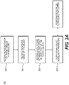
- FIG. 2A is a block diagram of an exemplary method 200 for creating a patient-specific model from multiple images, according to an exemplary embodiment of the present disclosure.
- patient images that are obtained via various imaging techniques or at different points in time may be compiled to create a final model.
- the final model created may depict different parts of anatomy or various aspects of the anatomy, depending on the input images.
- Some embodiments of the method may include first obtaining a model of the target anatomy object, to which patient images may be mapped. Other embodiments of the method may further include reference images that may serve as a point of comparison for such mapping.
- Method 200 may be performed by server systems 106, based on information, images, and data received from physicians 102 and/or third party providers 104 over electronic network 100. The method of FIG.
- the representation includes receiving a representation of a target object for modeling (step 202).
- the representation may be stored on an electronic storage device (e.g., hard drive, RAM, network drive, etc.).
- the representation includes an object localization model (a volumetric model).
- the representation may also include, but is not limited to, a boundary model, an appearance model or shape model.
- the representation is determined by a set of parameters estimated from the images.
- the object localization model includes a resultant object model based on the estimated parameters. For instance, the resultant object model is comprised of a fully determined set of parameters.
- a set of parameters to determine an object model is the assignment of a probability value to every pixel.
- An additional exemplary set of parameters to determine an object model is the assignment of a binary indicator value to every pixel or the assignment of a level set value to every pixel.
- Another additional set of parameters that may be used to represent an object model is a set of 3D coordinates and triangles to represent the triangulated surface of a 3D object.
- Step 204 of method 200 may involve receiving a reference image that depicts the target object.
- the reference image may be 2-D, 3-D, or 4-D, and the image may be stored in an electronic storage device.
- the reference image may be directly associated with the target object.
- the reference image may be selected based on inferences from the resultant object model.
- step 206 may involve receiving a collection of two or more 2-D, 3-D, or 4-D images that depict at least part of the target object.
- This collection of images is specific to the patient.
- the images are stored and/or transferred via an electronic storage device.
- image refers to an image regardless of dimension.
- each element making up the image may be referred to as a "pixel” or "voxel,” regardless of the image size or resolution.
- each element of a 2-D image may be a pixel, regardless of the image dimensions.
- each element of a 3-D image or volumetric model may be regarded as a "voxel,” for images or models of any size or resolution.
- Step 208 of method 200 may include processing the representation from step 202, the reference image from step 204, and image collection of step 206 to output final object model parameters.
- step 208 may include outputting the parameters to an electronic storage device and/or performing the processing using a computational device (including but not limited to a computer, laptop, DSP, cloud server, tablet, smart phone, etc.).
- a computational device including but not limited to a computer, laptop, DSP, cloud server, tablet, smart phone, etc.
- method 220 of FIG. 2B may be an exemplary method for performing the processing of step 208.
- method 200 may employ method 220 to process gathered information and produce the final object parameters output in step 208.
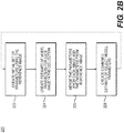
- FIG. 2B is a block diagram of an exemplary method 220 for processing various images and/or sets of images to produce final object parameters, according to an exemplary embodiment of the present disclosure.
- Method 220 may also be performed by server systems 106, based on information, images, and data received from physicians 102 and/or third party providers 104 over electronic network 100.
- the method of FIG. 2B may include creating an initial set of parameters for the object model using the reference image (step 222).
- initial parameters may be determined by using an image segmentation technique.
- step 222 may include defining a set of parameters of interest for the object model, and then determining the parameters for the reference image. Alternately, step 222 may include determining a set of parameters available from the reference image. Step 222 may further include determining values of each of the parameters. In some cases, this set of parameters may serve as initialized parameters.
- Step 224 may include creating an estimate of some of the object model parameters for each image in the collection (received in step 206).
- the initialized parameters from step 222 may or may not be used to create the estimate. For example, estimates may be made of more object parameters than are included in the set of initialized parameters. Alternately, estimates may be made for only a subset of the initialized parameters or the full set of initialized parameters.
- step 226 includes updating or merging the parameters from each image in the collection with parameters and parameter values estimated from the reference image.
- image parameters from a first set of image parameters are updated based on image parameters obtained from a second set of images.
- Image parameters are merged by combining and/or averaging corresponding image parameters obtained from multiple sets of images.
- updating parameters may include, both changes or verification of existing parameters, as well as generating new parameters.
- step 226 may lead to step 228 of creating a combined estimate of the object.
- steps 222-228 may be repeated until the object model parameters converge.
- the object model parameters may converge into final object parameters. These final object parameters may serve as the output at step 208 of method 200, where final object parameters are output to an electronic storage device.
- Method 200 may be used to produce various models, depending on the patient images used in step 206 and the processing of those images in method 220.
- the following disclosure presents several exemplary embodiments of, or alternatives to method 200.
- FIGs. 3A -3C are block diagrams of exemplary methods for obtaining volumetric models of probabilities that given voxels belong to a patient lumen. All of the images and final object models discussed may be stored in and/or output to electronic storage devices.
- FIGs. 3A-3B depict methods for coronary vessel modeling, where a final volumetric model includes probabilities that each voxel belongs to a patient coronary vessel lumen.
- a final volumetric model includes probabilities that each voxel belongs to a patient coronary vessel lumen.
- different imaging techniques may produce patient images that each portray a coronary vessel lumen in some capacity.
- Each element (e.g., voxel) of each image may carry some probability that it is part of a vessel. Forming a composite of the images may therefore produce an accurate model of a patient coronary vessel lumen.
- the model may further include an assessment of the model's accuracy at any point in the model.
- FIG. 3A is an exemplary method of estimating the probabilities using CTA reconstructions
- FIG. 3B is an exemplary method of modeling using cardiac CTA images at different points in time.
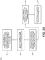
- FIG. 3A is a block diagram of an exemplary method 300 for obtaining volumetric models of probabilities based on CTA reconstructions.
- coronary vessels may be segmented using multiple cCTA images that represent multiple reconstructions.
- a parameterized representation of a target object may be received and stored on an electric storage device (e.g., hard drive, RAM, network drive, etc.) (step 301).
- the target object is the coronary vessel lumen.
- the representation for step 301 is a volumetric model of a patient's coronary vessel lumen, where each voxel represents the probability that the voxel belongs to the patient's coronary vessel lumen.
- Probabilities may or may not be displayed.
- probabilities may be displayed by showing respective probabilities of each voxel belonging to the patient's coronary vessel lumen by displaying a high probability as a high image intensity and a low probability as a low image intensity.
- Step 303 may involve receiving multiple 3-D images from a cardiac CT scanner, where each image represents different reconstructions of the cCTA image for the patient.
- Reconstructions include images with different kernels for filtered backprojection and/or iterative reconstruction methods.
- Employing multiple reconstructions is useful in that each image reconstruction technique has different advantages and disadvantages for different types of image features.
- Each image reconstruction technique may be better for some types of image features and worse at others (e.g., blooming, streaking, noise, etc.). Using the best aspects of each reconstruction may help achieve a more precise object geometry.
- Step 305 involves determining the probability that each voxel belongs to the patient's coronary vessel lumen.
- the probability may be determined by performing a segmentation of the coronary vessel lumen in each image.
- any known technique for performing segmentation to obtain voxel probabilities may be used, such as random walker algorithms or machine learning algorithms that map voxel intensities and their neighbors to probabilities.
- the segmentation may be performed using any existing technique, and the segmentation may be performed for the coronary vessel lumen independently with respect to each image.
- segmentation may be performed automatically by a computer system either based on user inputs or without user inputs. For instance, in an exemplary embodiment, the user may provide inputs to the computer system in order to generate a first initial model.
- the computer system may display to the user a 3-D image or slices thereof produced from the CCTA data.
- the 3-D image may include portions of varying intensity of lightness. For example, lighter areas may indicate the lumens of the aorta, the main coronary arteries, and/or the branches. Darker areas may indicate the myocardium and other tissue of the patient's heart.
- Step 307 may involve averaging the probabilities (from step 305) across the images to create a combined estimate of the volumetric model of the probability of each voxel belonging to the patient lumen.
- steps 305 and 307 may be performed using a computer.
- the final, averaged volumetric model of the probabilities may be output (step 309), for example, to an electronic storage device.
- the averaged volumetric model of the probabilities may be output in the form of a color overlay showing the boundary of a level set on the probabilities, or as a set of raw probabilities.
- FIG. 3B is a block diagram of an exemplary method 320 for obtaining volumetric models of probabilities based on CTA images obtained at different points in time.
- step 321 involves obtaining a parameterized representation of a target object (e.g., a coronary vessel lumen).
- the representation may be a volumetric model of a patient's coronary vessel lumen in which each voxel represents the probability that the voxel belongs to the patient's coronary vessel lumen.
- step 323 may involve receiving multiple 3-D images from a cardiac CT scanner where each image represents a different reconstruction of the cCTA image for a patient.
- the images may represent acquisitions from a single patient, at multiple points in time (e.g., time points within the cardiac cycle or an initial acquisition and follow-up scan). Using images at multiple time points means that each image may contain independent information that may contain less artifact or better quality in different regions of the image. Method 320 may include using the best aspects of each reconstruction to achieve a final model of precise object geometry.
- the images for step 323 may be stored in an electronic storage device. For example, a storage device may determine a new image acquisition and update a final volumetric model by taking into account the new acquisition.
- Step 325a may reflect step 305 in determining the probability that each voxel belongs to the patient's coronary vessel lumen.
- step 325a may include finding the probability by performing a segmentation of the coronary vessel lumen independently in each image (using any existing technique).
- step 325b may involve choosing a reference image.
- the reference image may be arbitrary among the acquired images, retrieved from a reference image repository, selected intentionally from a set of acquired images, etc. Then, 3-D registration may be used to register each image to the reference image (step 325c).
- Step 327 may involve creating a combined estimate of the volumetric model by averaging probabilities across images.
- the images for step 327 may include patient images and the reference image.
- the image registration may be used to map each voxel to another voxel, meaning mapping a location in each image to a location (or locations) in the reference image and/or other images.
- the mapping may be performed using any method such that voxels in two images may be identified as being representations of the same part of the target object (e.g., coronary vessel lumen). Since the voxels correspond to the same part, the voxel probabilities may be combined.
- step 329 may include outputting the final volumetric model of the probabilities to an electronic storage device.
- modeling may be improved using multiple images, whether the variations are images acquired from different reconstructions. Creating models by aggregating multiple images reduces errors or imperfections in individual image acquisitions, and strengthens the credibility of the final model.
- the technique of modeling using multiple images may be applied to model any target object, anatomy of interest, or information associated with that target object and/or anatomy or interest.
Description
- Various embodiments of the present disclosure relate generally to medical imaging and related methods. More specifically, particular embodiments of the present disclosure relate to systems and methods for image-based object modeling using multiple image acquisitions or reconstructions.
- Medical imaging and extraction of anatomy from imaging is important, as evidenced by the many means of medical imaging available. Common forms of medical imaging include computed tomography (CT) scans, magnetic resonance imaging, intravascular ultrasound, intravascular optical coherence tomography, angiography, and histopathology optical images. CT scans are x-ray images of "slices" of a scanned object. For example, CT scans are commonly images taken as cross-sectional slices, perpendicular to the long axis of the body. Cardiac CT scans may include calcium-score screening and/or angiography. Calcium score screening scans may be used to detect calcium deposits in coronary arteries, contributing to predictions of heart problems. CT angiography is CT scanning including intravenous (IV) contrast dye to better show blood vessels and organs. Although also capable of producing tomographic images, magnetic resonance (MR) imaging uses magnetic field properties to create the images. Because CT and MRI images are produced differently, resultant images highlight different tissue properties. MR images offer better quality in soft tissue images than CT scans; CT scans image bone and blood vessels in addition to soft tissue, although the soft tissue detail is inferior to that of MR images. Depending on the anatomy of interest and purpose of imaging, CT and MR may be considered complimentary imaging techniques.
- Intravascular ultrasound (IVUS) is a type of imaging that visualizes the inside of blood vessels. Whereas CT and MR methods involve images taken as slices of a patient body, IVUS images are achieved via a catheter traveling through an artery or vein. Thus, IVUS images may essentially show cross-sections of the artery or vein, from the center of a blood vessel, out through the vessel wall and whatever diseased portion may exist at the wall. Intravascular optical coherence tomography (OCT) is an optical analog of the ultrasound imaging of IVUS. IVUS and OCT are analogous imaging modalities, but OCT's use of light (in place of sound) offers higher resolution images than IVUS. Briefly discussed in the context of CT scans, angiography is an imaging technique that employs an injection of a contrast agent into the blood stream to better show vessels or vessel openings. While CT angiography may be preferable for coronary disease detection, MR angiography is a viable alternative. Histopathological optical imaging includes visualization of tissue on a microscopic level. Histopathological imaging can be used to identify tissue or detect for various biomarkers. One common prerequisite for the analysis of histopathological images is the localization of cells, tissue or other anatomical and cellular objects within the images.
- It can be helpful to have an understanding of the normal variation inherent in human anatomy, for example to serve as a reference against which data for a particular patient can be compared in order to detect abnormality. Accordingly, various proposals have been made to generate statistical models of anatomical objects. Amongst the proposals that have been made are several which propose creating a statistical model or atlas by combining image data obtained for a group of patients, notably patients having a common demographical profile (e.g. same age, same gender, etc.) and sometimes including multimodal data, i.e. image data produced by different types of imaging technology. In this regard, reference may be made to
US2007/019846 ,US 2012/201442 , papers by Beck et al ("Statistical modeling of the arterial vascular tree", proc. SPIE 7962, Medical Imaging 2011: Image Processing, 12 February 2011, pages 1-6), and Nakamura et al (Segmentation of brain magnetic resonance images for measurement of gray matter atrophy in multiple sclerosis patients", Neuroimage, Academic Press, Orlando, Fl., USA, vol.44, no.3, 1 February 2009, pages 769-776) and an MSc thesis by Gao et al ("Development of human lung query atlas", Electrical & Computer Engineering in the Graduate College of The University of Iowa, December 2010, pages 1-117). - Based on images from techniques described above, anatomical models may be extracted to measure one or more properties of a patient's anatomy (e.g., a tumor or cardiac volume) or to support biophysical simulation (e.g., fluid simulation, biomechanical simulation, electrophysiological simulation, etc.). In order to accurately measure anatomical properties or predict physiological phenomena via simulation, a very precise patient-specific model must be created of the target anatomy. Imaging and subsequent extraction of anatomical models of the heart, for example, is of special importance. For instance, such imaging and modeling may provide evaluation of coronary artery disease, such as when a patient is suffering from chest pain, and/or a more severe manifestation of disease, such as myocardial infarction, or heart attack.
- Patients suffering from chest pain and/or exhibiting symptoms of coronary artery disease may be subjected to one or more tests that may provide some indirect evidence relating to coronary lesions. For example, noninvasive tests may include electrocardiograms, biomarker evaluation from blood tests, treadmill tests, echocardiography, single positron emission computed tomography (SPECT), and positron emission tomography (PET). These noninvasive tests, however, typically do not provide a direct assessment of coronary lesions or assess blood flow rates. The noninvasive tests may provide indirect evidence of coronary lesions by looking for changes in electrical activity of the heart (e.g., using electrocardiography (ECG)), motion of the myocardium (e.g., using stress echocardiography), perfusion of the myocardium (e.g., using PET or SPECT), or metabolic changes (e.g., using biomarkers). For example, anatomic data may be obtained noninvasively using coronary computed tomographic angiography (CCTA). CCTA may be used for imaging of patients with chest pain and involves using CT technology to image the heart and the coronary arteries following an intravenous infusion of a contrast agent.
- However, single images may be insufficient to create ideal models. The foregoing general description and the following detailed description are exemplary and explanatory only and are not restrictive of the disclosure.
- In "Model-based Segmentation of Medical Imagery by Matching Distributions", by Freedman et al (IEEE Transactions on Medical Imaging, vol.24, no.3, 1 March 2005, pages 281-292) techniques are described for segmenting deformable objects represented in 3D images, such as bodily organs shown in CT scans. Freedman et al describe a method of creating a shape model of a patient's prostate from a training data set containing a plurality of CT images of the male pelvis taken from the same patient over several days.
- According to certain aspects of the present disclosure, systems and methods are disclosed for modeling at least a portion of a patient's anatomy. The present invention provides a computer-implemented method of modeling at least a portion of a patient's anatomy, using a computer system, as recited in appended claim 1.
- The present invention further provides a system for modeling at least a portion of a patient's anatomy, as recited in appended claim 7.
- The present invention further provides a non-transitory computer readable medium for use on a computer system, as recited in appended claim 8.
- Additional objects and advantages of the disclosed embodiments will be set forth in part in the description that follows, and in part will be apparent from the description, or may be learned by practice of the disclosed embodiments. The objects and advantages of the disclosed embodiments will be realized and attained by means of the elements and combinations particularly pointed out in the appended claims.
- It is to be understood that both the foregoing general description and the following detailed description are exemplary and explanatory only and are not restrictive of the disclosed embodiments, as claimed.
- The accompanying drawings, which are incorporated in and constitute a part of this specification, illustrate various exemplary embodiments and together with the description, serve to explain the principles of the disclosed embodiments.
-
FIG. 1 is a block diagram of an exemplary system and network for generating models from multiple patient-specific anatomic images, according to an exemplary embodiment of the present disclosure. -
FIG. 2A is a block diagram of an exemplary method for creating a patient-specific model from multiple images, according to an exemplary embodiment of the present disclosure. -
FIG. 2B is a block diagram of an exemplary method for processing various images and/or sets of images to produce final object parameters, according to an exemplary embodiment of the present disclosure. -
FIGs. 3A-3B are block diagrams of exemplary methods for coronary vessel modeling, where a final volumetric model includes probabilities that each voxel belongs to patient coronary vessel lumen, according to an exemplary embodiment of the present disclosure. - Reference will now be made in detail to the exemplary embodiments of the invention, examples of which are illustrated in the accompanying drawings. Wherever possible, the same reference numbers will be used throughout the drawings to refer to the same or like parts.
- As described above, a new generation of noninvasive tests have been developed that is based on modeling anatomy. Thus, a need exists for accurate modeling. Specifically, there is a need for accurately modeling coronary anatomy to assess patient anatomy, myocardial perfusion, and coronary artery flow. Such a method and system may benefit cardiologists who diagnose and plan treatments for patients with suspected coronary artery disease.
- However, because image-based models generated from single images may be insufficient, a need exists for a method for modeling anatomy that may integrate imaging data from multiple sources. For example, compiling multiple images to produce a model may enhance complimentary information in each of the multiple images and reduce imaging artifact in various images. As an exemplary embodiment, a method for modeling coronary anatomy is described in order to noninvasively assess coronary anatomy, myocardial perfusion, and coronary artery flow. However, such a method and system may be suitable for any anatomy of interest. By extension, reinforcing the advantages of each imaging technique by integrating multiple images may also reduce the impact of disadvantages (e.g., imaging artifacts) associated with various imaging techniques.
- Thus, the present disclosure is directed to a new approach of using multiple images in order to create and provide an accurate anatomical model. The extraction of an anatomical model from an image is a common problem in biomedical imaging. Anatomical models may be extracted to measure properties of patient anatomy (e.g., tumor or cardiac volume) or to support biophysical simulation (e.g., fluid simulation, biomechanical simulation, electrophysiological simulation, etc.). In order to accurately measure anatomical properties or predict physiological phenomena via simulation, a precise, patient-specific model must be created of the target anatomy. The present disclosure involves the use of multiple images to achieve a patient-specific anatomical model. For example, the present disclosure may take advantage of complementary information in each of the multiple images or a reduction in different types of imaging artifact in the different images. Although it is possible to construct patient-specific models from geometry derived from a single image, use of multiple images produces a hyper-precise patient-specific anatomical model.
- The present disclosure is directed to integrating imaging data from multiple sources to create a single, precise geometric model. Specifically, the present disclosure may receive various types of images or different portions of a target object. The present disclosure may average respective reference images with multiple patient images to create a single geometric model.
- Referring now to the figures,
FIG. 1 depicts a block diagram of an exemplary system and network for predicting coronary plaque vulnerability from patient-specific anatomic image data. Specifically,FIG. 1 depicts a plurality ofphysicians 102 andthird party providers 104, any of whom may be connected to anelectronic network 100, such as the Internet, through one or more computers, servers, and/or handheld mobile devices.Physicians 102 and/orthird party providers 104 may create or otherwise obtain images of one or more patients' cardiac and/or vascular systems. Thephysicians 102 and/orthird party providers 104 may also obtain any combination of patient-specific information, such as age, medical history, blood pressure, blood viscosity, etc.Physicians 102 and/orthird party providers 104 may transmit the cardiac/vascular images and/or patient-specific information toserver systems 106 over theelectronic network 100.Server systems 106 may include storage devices for storing images and data received fromphysicians 102 and/orthird party providers 104.Server systems 106 may also include processing devices for processing images and data stored in the storage devices. -
FIG. 2A is a block diagram of anexemplary method 200 for creating a patient-specific model from multiple images, according to an exemplary embodiment of the present disclosure. For example, patient images that are obtained via various imaging techniques or at different points in time may be compiled to create a final model. The final model created may depict different parts of anatomy or various aspects of the anatomy, depending on the input images. Some embodiments of the method may include first obtaining a model of the target anatomy object, to which patient images may be mapped. Other embodiments of the method may further include reference images that may serve as a point of comparison for such mapping.Method 200 may be performed byserver systems 106, based on information, images, and data received fromphysicians 102 and/orthird party providers 104 overelectronic network 100. The method ofFIG. 2A includes receiving a representation of a target object for modeling (step 202). In one embodiment, the representation may be stored on an electronic storage device (e.g., hard drive, RAM, network drive, etc.). The representation includes an object localization model (a volumetric model). The representation may also include, but is not limited to, a boundary model, an appearance model or shape model. In one embodiment, the representation is determined by a set of parameters estimated from the images. The object localization model includes a resultant object model based on the estimated parameters. For instance, the resultant object model is comprised of a fully determined set of parameters. A set of parameters to determine an object model is the assignment of a probability value to every pixel. An additional exemplary set of parameters to determine an object model is the assignment of a binary indicator value to every pixel or the assignment of a level set value to every pixel. Another additional set of parameters that may be used to represent an object model is a set of 3D coordinates and triangles to represent the triangulated surface of a 3D object. - Step 204 of
method 200 may involve receiving a reference image that depicts the target object. For example, the reference image may be 2-D, 3-D, or 4-D, and the image may be stored in an electronic storage device. In one case, the reference image may be directly associated with the target object. In another case, the reference image may be selected based on inferences from the resultant object model. - Then, step 206 may involve receiving a collection of two or more 2-D, 3-D, or 4-D images that depict at least part of the target object. This collection of images is specific to the patient. In one case, the images are stored and/or transferred via an electronic storage device. As used herein, the term, "image," refers to an image regardless of dimension. In addition, each element making up the image may be referred to as a "pixel" or "voxel," regardless of the image size or resolution. For example, each element of a 2-D image may be a pixel, regardless of the image dimensions. Analogously, each element of a 3-D image or volumetric model may be regarded as a "voxel," for images or models of any size or resolution. Step 208 of
method 200 may include processing the representation fromstep 202, the reference image fromstep 204, and image collection ofstep 206 to output final object model parameters. For example, step 208 may include outputting the parameters to an electronic storage device and/or performing the processing using a computational device (including but not limited to a computer, laptop, DSP, cloud server, tablet, smart phone, etc.). In one embodiment,method 220 ofFIG. 2B may be an exemplary method for performing the processing ofstep 208. In other words,method 200 may employmethod 220 to process gathered information and produce the final object parameters output instep 208. -
FIG. 2B is a block diagram of anexemplary method 220 for processing various images and/or sets of images to produce final object parameters, according to an exemplary embodiment of the present disclosure.Method 220 may also be performed byserver systems 106, based on information, images, and data received fromphysicians 102 and/orthird party providers 104 overelectronic network 100. The method ofFIG. 2B may include creating an initial set of parameters for the object model using the reference image (step 222). For example, in one embodiment, initial parameters may be determined by using an image segmentation technique. For example, step 222 may include defining a set of parameters of interest for the object model, and then determining the parameters for the reference image. Alternately, step 222 may include determining a set of parameters available from the reference image. Step 222 may further include determining values of each of the parameters. In some cases, this set of parameters may serve as initialized parameters. - Step 224 may include creating an estimate of some of the object model parameters for each image in the collection (received in step 206). The initialized parameters from
step 222 may or may not be used to create the estimate. For example, estimates may be made of more object parameters than are included in the set of initialized parameters. Alternately, estimates may be made for only a subset of the initialized parameters or the full set of initialized parameters. - In one embodiment,
step 226 includes updating or merging the parameters from each image in the collection with parameters and parameter values estimated from the reference image. In one embodiment, image parameters from a first set of image parameters are updated based on image parameters obtained from a second set of images. Image parameters are merged by combining and/or averaging corresponding image parameters obtained from multiple sets of images. Furthermore, updating parameters may include, both changes or verification of existing parameters, as well as generating new parameters. By merging the parameters, step 226 may lead to step 228 of creating a combined estimate of the object. In one embodiment, steps 222-228 may be repeated until the object model parameters converge. The object model parameters may converge into final object parameters. These final object parameters may serve as the output atstep 208 ofmethod 200, where final object parameters are output to an electronic storage device. -
Method 200 may be used to produce various models, depending on the patient images used instep 206 and the processing of those images inmethod 220. The following disclosure presents several exemplary embodiments of, or alternatives tomethod 200. In general,FIGs. 3A -3C are block diagrams of exemplary methods for obtaining volumetric models of probabilities that given voxels belong to a patient lumen. All of the images and final object models discussed may be stored in and/or output to electronic storage devices. -
FIGs. 3A-3B depict methods for coronary vessel modeling, where a final volumetric model includes probabilities that each voxel belongs to a patient coronary vessel lumen. For example, different imaging techniques may produce patient images that each portray a coronary vessel lumen in some capacity. Each element (e.g., voxel) of each image may carry some probability that it is part of a vessel. Forming a composite of the images may therefore produce an accurate model of a patient coronary vessel lumen. The model may further include an assessment of the model's accuracy at any point in the model. In general,FIG. 3A is an exemplary method of estimating the probabilities using CTA reconstructions; andFIG. 3B is an exemplary method of modeling using cardiac CTA images at different points in time. -
FIG. 3A is a block diagram of anexemplary method 300 for obtaining volumetric models of probabilities based on CTA reconstructions. In one embodiment, coronary vessels may be segmented using multiple cCTA images that represent multiple reconstructions. First, a parameterized representation of a target object may be received and stored on an electric storage device (e.g., hard drive, RAM, network drive, etc.) (step 301). The target object is the coronary vessel lumen. In particular, the representation forstep 301 is a volumetric model of a patient's coronary vessel lumen, where each voxel represents the probability that the voxel belongs to the patient's coronary vessel lumen. Probabilities may or may not be displayed. For example, in one embodiment, probabilities may be displayed by showing respective probabilities of each voxel belonging to the patient's coronary vessel lumen by displaying a high probability as a high image intensity and a low probability as a low image intensity. - Step 303 may involve receiving multiple 3-D images from a cardiac CT scanner, where each image represents different reconstructions of the cCTA image for the patient. Reconstructions include images with different kernels for filtered backprojection and/or iterative reconstruction methods. Employing multiple reconstructions is useful in that each image reconstruction technique has different advantages and disadvantages for different types of image features. Each image reconstruction technique may be better for some types of image features and worse at others (e.g., blooming, streaking, noise, etc.). Using the best aspects of each reconstruction may help achieve a more precise object geometry.
- Step 305 involves determining the probability that each voxel belongs to the patient's coronary vessel lumen. For example, the probability may be determined by performing a segmentation of the coronary vessel lumen in each image. For example, any known technique for performing segmentation to obtain voxel probabilities may be used, such as random walker algorithms or machine learning algorithms that map voxel intensities and their neighbors to probabilities. The segmentation may be performed using any existing technique, and the segmentation may be performed for the coronary vessel lumen independently with respect to each image. For example, segmentation may be performed automatically by a computer system either based on user inputs or without user inputs. For instance, in an exemplary embodiment, the user may provide inputs to the computer system in order to generate a first initial model. For another example, the computer system may display to the user a 3-D image or slices thereof produced from the CCTA data. The 3-D image may include portions of varying intensity of lightness. For example, lighter areas may indicate the lumens of the aorta, the main coronary arteries, and/or the branches. Darker areas may indicate the myocardium and other tissue of the patient's heart.
- Step 307 may involve averaging the probabilities (from step 305) across the images to create a combined estimate of the volumetric model of the probability of each voxel belonging to the patient lumen. In one embodiment, steps 305 and 307 may be performed using a computer. Finally, the final, averaged volumetric model of the probabilities may be output (step 309), for example, to an electronic storage device. For example, the averaged volumetric model of the probabilities may be output in the form of a color overlay showing the boundary of a level set on the probabilities, or as a set of raw probabilities.
-
FIG. 3B is a block diagram of anexemplary method 320 for obtaining volumetric models of probabilities based on CTA images obtained at different points in time. As inmethod 320,step 321 involves obtaining a parameterized representation of a target object (e.g., a coronary vessel lumen). The representation may be a volumetric model of a patient's coronary vessel lumen in which each voxel represents the probability that the voxel belongs to the patient's coronary vessel lumen. Similar to step 303,step 323 may involve receiving multiple 3-D images from a cardiac CT scanner where each image represents a different reconstruction of the cCTA image for a patient. Unique tomethod 320, the images may represent acquisitions from a single patient, at multiple points in time (e.g., time points within the cardiac cycle or an initial acquisition and follow-up scan). Using images at multiple time points means that each image may contain independent information that may contain less artifact or better quality in different regions of the image.Method 320 may include using the best aspects of each reconstruction to achieve a final model of precise object geometry. The images forstep 323 may be stored in an electronic storage device. For example, a storage device may determine a new image acquisition and update a final volumetric model by taking into account the new acquisition. -
Step 325a may reflectstep 305 in determining the probability that each voxel belongs to the patient's coronary vessel lumen. For example,step 325a may include finding the probability by performing a segmentation of the coronary vessel lumen independently in each image (using any existing technique). Next,step 325b may involve choosing a reference image. For example, the reference image may be arbitrary among the acquired images, retrieved from a reference image repository, selected intentionally from a set of acquired images, etc. Then, 3-D registration may be used to register each image to the reference image (step 325c). -
Step 327, likestep 307, may involve creating a combined estimate of the volumetric model by averaging probabilities across images. However, the images forstep 327 may include patient images and the reference image. The image registration may be used to map each voxel to another voxel, meaning mapping a location in each image to a location (or locations) in the reference image and/or other images. The mapping may be performed using any method such that voxels in two images may be identified as being representations of the same part of the target object (e.g., coronary vessel lumen). Since the voxels correspond to the same part, the voxel probabilities may be combined. Therefore, averaging the probability of each voxel belonging to the patient lumen may create a merged, averaged voxel probability for each voxel. Finally, step 329 may include outputting the final volumetric model of the probabilities to an electronic storage device. - Thus, modeling may be improved using multiple images, whether the variations are images acquired from different reconstructions. Creating models by aggregating multiple images reduces errors or imperfections in individual image acquisitions, and strengthens the credibility of the final model. The technique of modeling using multiple images may be applied to model any target object, anatomy of interest, or information associated with that target object and/or anatomy or interest.
- Other embodiments of the invention will be apparent to those skilled in the art from consideration of the specification and practice of the invention disclosed herein. It is intended that the specification and examples be considered as exemplary only, with the scope of the invention being indicated by the following claims.
Claims (8)
- A computer-implemented method of modeling at least a portion of a patient's anatomy, using a computer system, the method comprising:determining (224) one or more first anatomical parameters of a target anatomical object from at least one of one or more first images;determining (224) one or more second anatomical parameters of the target anatomical object from at least one of one or more second images;combining (226) the one or more first anatomical parameters with the one or more second anatomical parameters; andgenerating (228) a model of the target anatomical object based at least on the combination of the one or more first anatomical parameters with the one or more second anatomical parameters;wherein the model is a model of a vessel lumen, and the model includes a plurality of voxels representing a probability that each of the plurality of voxels belongs to the patient's vessel lumen;characterized in thatthe vessel lumen is a coronary vessel lumen;the first and second images include computed tomography (CT) scans of the same patient and the generating generates a model specific to saidpatient; andthe one or more first images include one or more computed tomography (CT) scans obtained using a first reconstruction method, and the one or more second images include one or more CT scans obtained using a second reconstruction method different from the first reconstruction method.
- The method of claim 1, wherein the one or more first images include one or more CT scans obtained at a first time, and the one or more second images include one or more CT scans obtained at a second time that is different from the first time.
- The method of claim 1, wherein combining of the first and second anatomical parameters includes determining the average of a probability that a voxel of a first image belongs to the patient's coronary vessel lumen and a probability that a voxel of a second image belongs to the patient's coronary vessel lumen.
- The method of claim 1, wherein the determining of said one or more first or second anatomical parameters includes performing segmentation (305) of at least one of the first images or at least one of the second images to determine a probability that a portion of the image data represents a portion of the target anatomical object based on the segmentation.
- The method of claim 4, wherein combining the first and second anatomical parameters includes averaging a probability that a portion of a first image represents a portion of the target anatomical object with a probability that a portion of a second image represents the portion of the target anatomical object.
- The method of claim 2, further comprising:designating (204) one of the first images or second images as a reference image;using image registration to register each of the one or more first images and each of the one or more second images to the reference image; andcombining the first and second anatomical parameters by determining the average of a probability that a portion of each first image represents a portion of the target anatomical object and a probability that a portion of each second image represents the portion of the target anatomical object.
- A system of modeling at least a portion of a patient's anatomy, the system (106) comprising:a data storage device storing instructions for modeling based on patient-specific anatomic image data; anda processor configured to execute the instructions to perform a method according to any one of claims 1 to 6.
- A non-transitory computer readable medium for use on a computer system containing computer-executable programming instructions for modeling at least a portion of a patient's anatomy, when the instructions are executed on the computer system, according to a method according to any one of claims 1 to 6.
Priority Applications (1)
| Application Number | Priority Date | Filing Date | Title |
|---|---|---|---|
| EP21217448.6A EP4002269A1 (en) | 2014-04-16 | 2015-04-14 | Systems and methods for image-based object modeling using multiple image acquisitions or reconstructions |
Applications Claiming Priority (2)
| Application Number | Priority Date | Filing Date | Title |
|---|---|---|---|
| US14/254,491 US9058692B1 (en) | 2014-04-16 | 2014-04-16 | Systems and methods for image-based object modeling using multiple image acquisitions or reconstructions |
| PCT/US2015/025691 WO2015160763A1 (en) | 2014-04-16 | 2015-04-14 | Systems and methods for image-based object modeling using multiple image acquisitions or reconstructions |
Related Child Applications (1)
| Application Number | Title | Priority Date | Filing Date |
|---|---|---|---|
| EP21217448.6A Division EP4002269A1 (en) | 2014-04-16 | 2015-04-14 | Systems and methods for image-based object modeling using multiple image acquisitions or reconstructions |
Publications (2)
| Publication Number | Publication Date |
|---|---|
| EP3132419A1 EP3132419A1 (en) | 2017-02-22 |
| EP3132419B1 true EP3132419B1 (en) | 2021-12-29 |
Family
ID=53053088
Family Applications (2)
| Application Number | Title | Priority Date | Filing Date |
|---|---|---|---|
| EP15720834.9A Active EP3132419B1 (en) | 2014-04-16 | 2015-04-14 | Systems and methods for image-based object modeling using multiple image acquisitions or reconstructions |
| EP21217448.6A Pending EP4002269A1 (en) | 2014-04-16 | 2015-04-14 | Systems and methods for image-based object modeling using multiple image acquisitions or reconstructions |
Family Applications After (1)
| Application Number | Title | Priority Date | Filing Date |
|---|---|---|---|
| EP21217448.6A Pending EP4002269A1 (en) | 2014-04-16 | 2015-04-14 | Systems and methods for image-based object modeling using multiple image acquisitions or reconstructions |
Country Status (4)
| Country | Link |
|---|---|
| US (6) | US9058692B1 (en) |
| EP (2) | EP3132419B1 (en) |
| JP (2) | JP6409073B2 (en) |
| WO (1) | WO2015160763A1 (en) |
Families Citing this family (29)
| Publication number | Priority date | Publication date | Assignee | Title |
|---|---|---|---|---|
| US9135381B2 (en) | 2013-05-10 | 2015-09-15 | Stenomics, Inc. | Modeling and simulation system for optimizing prosthetic heart valve treatment |
| US9092743B2 (en) | 2013-10-23 | 2015-07-28 | Stenomics, Inc. | Machine learning system for assessing heart valves and surrounding cardiovascular tracts |
| US9514530B2 (en) | 2014-04-16 | 2016-12-06 | Heartflow, Inc. | Systems and methods for image-based object modeling using multiple image acquisitions or reconstructions |
| US11071501B2 (en) | 2015-08-14 | 2021-07-27 | Elucid Bioiwaging Inc. | Quantitative imaging for determining time to adverse event (TTE) |
| US10176408B2 (en) | 2015-08-14 | 2019-01-08 | Elucid Bioimaging Inc. | Systems and methods for analyzing pathologies utilizing quantitative imaging |
| US11676359B2 (en) | 2015-08-14 | 2023-06-13 | Elucid Bioimaging Inc. | Non-invasive quantitative imaging biomarkers of atherosclerotic plaque biology |
| US11113812B2 (en) | 2015-08-14 | 2021-09-07 | Elucid Bioimaging Inc. | Quantitative imaging for detecting vulnerable plaque |
| US11087459B2 (en) | 2015-08-14 | 2021-08-10 | Elucid Bioimaging Inc. | Quantitative imaging for fractional flow reserve (FFR) |
| US11094058B2 (en) | 2015-08-14 | 2021-08-17 | Elucid Bioimaging Inc. | Systems and method for computer-aided phenotyping (CAP) using radiologic images |
| US10236084B2 (en) | 2015-11-10 | 2019-03-19 | Heartflow, Inc. | Systems and methods for anatomical modeling using information obtained from a medical procedure |
| US10354378B2 (en) | 2016-04-06 | 2019-07-16 | University Of Washington | Systems and methods for quantitative assessment of microvasculature using optical coherence tomography angiography |
| EP3457930B1 (en) | 2016-05-16 | 2023-11-15 | Cathworks Ltd. | System for vascular assessment |
| EP4241694A3 (en) | 2016-05-16 | 2023-12-20 | Cathworks Ltd. | Selection of vascular paths from images |
| US10398382B2 (en) * | 2016-11-03 | 2019-09-03 | Siemens Medical Solutions Usa, Inc. | Respiratory motion estimation in projection domain in nuclear medical imaging |
| US10789706B2 (en) * | 2016-12-23 | 2020-09-29 | Heartflow, Inc. | Systems and methods for medical acquisition processing and machine learning for anatomical assessment |
| US11813104B2 (en) | 2017-10-06 | 2023-11-14 | Emory University | Methods and systems for determining hemodynamic information for one or more arterial segments |
| US11771321B2 (en) | 2017-10-13 | 2023-10-03 | The Research Foundation For Suny | System, method, and computer-accessible medium for subsurface capillary flow imaging by wavelength-division-multiplexing swept-source optical doppler tomography |
| EP3471054B1 (en) * | 2017-10-16 | 2022-02-09 | Siemens Healthcare GmbH | Method for determining at least one object feature of an object |
| US11871995B2 (en) | 2017-12-18 | 2024-01-16 | Hemolens Diagnostics Sp. Z O.O. | Patient-specific modeling of hemodynamic parameters in coronary arteries |
| US10813612B2 (en) | 2019-01-25 | 2020-10-27 | Cleerly, Inc. | Systems and method of characterizing high risk plaques |
| EP3899864A4 (en) | 2019-08-05 | 2022-08-31 | Elucid Bioimaging Inc. | Combined assessment of morphological and perivascular disease markers |
| CN110853021B (en) * | 2019-11-13 | 2020-11-24 | 江苏迪赛特医疗科技有限公司 | Construction of detection classification model of pathological squamous epithelial cells |
| US20220392065A1 (en) | 2020-01-07 | 2022-12-08 | Cleerly, Inc. | Systems, methods, and devices for medical image analysis, diagnosis, risk stratification, decision making and/or disease tracking |
| US11288799B2 (en) | 2020-01-07 | 2022-03-29 | Cleerly, Inc. | Systems, methods, and devices for medical image analysis, diagnosis, risk stratification, decision making and/or disease tracking |
| CA3162872A1 (en) | 2020-01-07 | 2021-07-15 | James K. MIN | Systems, methods, and devices for medical image analysis, diagnosis, risk stratification, decision making and/or disease tracking |
| EP4178446A4 (en) * | 2020-08-10 | 2023-06-07 | Shanghai United Imaging Healthcare Co., Ltd. | Imaging systems and methods |
| EP4002288A1 (en) * | 2020-11-12 | 2022-05-25 | Koninklijke Philips N.V. | Methods and systems for rendering representations of subject vasculature |
| EP4084011A1 (en) * | 2021-04-30 | 2022-11-02 | Siemens Healthcare GmbH | Computer-implemented method and evaluation system for evaluating at least one image data set of an imaging region of a patient, computer program and electronically readable storage medium |
| US20230289963A1 (en) | 2022-03-10 | 2023-09-14 | Cleerly, Inc. | Systems, devices, and methods for non-invasive image-based plaque analysis and risk determination |
Family Cites Families (59)
| Publication number | Priority date | Publication date | Assignee | Title |
|---|---|---|---|---|
| TWI221406B (en) * | 2001-07-30 | 2004-10-01 | Epix Medical Inc | Systems and methods for targeted magnetic resonance imaging of the vascular system |
| WO2005020790A2 (en) * | 2003-08-21 | 2005-03-10 | Ischem Corporation | Automated methods and systems for vascular plaque detection and analysis |
| US8090164B2 (en) * | 2003-08-25 | 2012-01-03 | The University Of North Carolina At Chapel Hill | Systems, methods, and computer program products for analysis of vessel attributes for diagnosis, disease staging, and surgical planning |
| US8010175B2 (en) * | 2004-05-05 | 2011-08-30 | Siemens Medical Solutions Usa, Inc. | Patient-specific coronary territory mapping |
| US20060036167A1 (en) | 2004-07-03 | 2006-02-16 | Shina Systems Ltd. | Vascular image processing |
| WO2006036842A2 (en) * | 2004-09-24 | 2006-04-06 | The University Of North Carolina At Chapel Hill | Methods, systems, and computer program products for hierarchical registration between a blood vessel and tissue surface model for a subject and blood vessel and tissue surface image for the subject |
| US8352013B2 (en) * | 2005-01-18 | 2013-01-08 | Siemens Medical Solutions Usa, Inc. | Method and system for motion compensation in magnetic resonance (MR) imaging |
| US8285011B2 (en) | 2005-06-02 | 2012-10-09 | M2S | Anatomical visualization and measurement system |
| EP1903944B1 (en) * | 2005-06-24 | 2017-04-19 | Volcano Corporation | Co-registration of graphical image data representing three-dimensional vascular features |
| US8406851B2 (en) * | 2005-08-11 | 2013-03-26 | Accuray Inc. | Patient tracking using a virtual image |
| WO2007020555A2 (en) * | 2005-08-17 | 2007-02-22 | Koninklijke Philips Electronics N.V. | Method and apparatus for automatic 4d coronary modeling and motion vector field estimation |
| US20080033302A1 (en) * | 2006-04-21 | 2008-02-07 | Siemens Corporate Research, Inc. | System and method for semi-automatic aortic aneurysm analysis |
| US8923577B2 (en) * | 2006-09-28 | 2014-12-30 | General Electric Company | Method and system for identifying regions in an image |
| US8781193B2 (en) * | 2007-03-08 | 2014-07-15 | Sync-Rx, Ltd. | Automatic quantitative vessel analysis |
| WO2008110013A1 (en) * | 2007-03-15 | 2008-09-18 | Centre Hospitalier De L'universite De Montreal | Image segmentation |
| US8666128B2 (en) * | 2007-10-18 | 2014-03-04 | The University Of North Carolina At Chapel Hill | Methods, systems, and computer readable media for mapping regions in a model of an object comprising an anatomical structure from one image data set to images used in a diagnostic or therapeutic intervention |
| WO2009049681A1 (en) * | 2007-10-19 | 2009-04-23 | Vascops | Automatic geometrical and mechanical analyzing method and system for tubular structures |
| US8218845B2 (en) * | 2007-12-12 | 2012-07-10 | Siemens Aktiengesellschaft | Dynamic pulmonary trunk modeling in computed tomography and magnetic resonance imaging based on the detection of bounding boxes, anatomical landmarks, and ribs of a pulmonary artery |
| JP5241357B2 (en) * | 2008-07-11 | 2013-07-17 | 三菱プレシジョン株式会社 | Biological data model creation method and apparatus |
| JP5009391B2 (en) * | 2009-07-03 | 2012-08-22 | 富士フイルム株式会社 | Diagnosis support apparatus, diagnosis support program, and diagnosis support method |
| BR112012002884A2 (en) * | 2009-08-12 | 2017-12-19 | Koninl Philips Electronics Nv | medical imaging system for generating data of an object of characteristics of a region of interest of an object, method for generating data of an object of characteristics of a region of interest of an object, computer program element for controlling a machine and a half that can be read by computer |
| US8224640B2 (en) * | 2009-09-08 | 2012-07-17 | Siemens Aktiengesellschaft | Method and system for computational modeling of the aorta and heart |
| US8478012B2 (en) * | 2009-09-14 | 2013-07-02 | General Electric Company | Methods, apparatus and articles of manufacture to process cardiac images to detect heart motion abnormalities |
| GB2478329B (en) * | 2010-03-03 | 2015-03-04 | Samsung Electronics Co Ltd | Medical image processing |
| EP2545527B1 (en) * | 2010-03-11 | 2014-07-02 | Koninklijke Philips N.V. | Probabilistic refinement of model-based segmentation |
| US8315812B2 (en) | 2010-08-12 | 2012-11-20 | Heartflow, Inc. | Method and system for patient-specific modeling of blood flow |
| JP4937397B2 (en) * | 2010-10-25 | 2012-05-23 | 富士フイルム株式会社 | Medical image diagnosis support apparatus and method, and program |
| DE102011076233B4 (en) * | 2011-02-09 | 2013-04-18 | Siemens Aktiengesellschaft | Method and computer system for detecting a statistically relevant standard variant of the vascular structure of a patient with the aid of tomographic image data sets |
| WO2012112929A2 (en) * | 2011-02-17 | 2012-08-23 | The Johns Hopkins University | Methods and systems for registration of radiological images |
| US8761474B2 (en) * | 2011-07-25 | 2014-06-24 | Siemens Aktiengesellschaft | Method for vascular flow pattern analysis |
| US8948487B2 (en) * | 2011-09-28 | 2015-02-03 | Siemens Aktiengesellschaft | Non-rigid 2D/3D registration of coronary artery models with live fluoroscopy images |
| WO2013085061A1 (en) * | 2011-12-08 | 2013-06-13 | オリンパス株式会社 | Image processor, image processing method, and image processing program |
| US9842194B2 (en) * | 2012-02-13 | 2017-12-12 | Koninklijke Philips N.V. | Simplified method for robust estimation of parameter values |
| US9384546B2 (en) * | 2012-02-22 | 2016-07-05 | Siemens Aktiengesellschaft | Method and system for pericardium based model fusion of pre-operative and intra-operative image data for cardiac interventions |
| US20150185298A1 (en) * | 2012-06-05 | 2015-07-02 | The University Of Queensland | Method of estimating specific absorption rate |
| US8958618B2 (en) * | 2012-06-28 | 2015-02-17 | Kabushiki Kaisha Toshiba | Method and system for identification of calcification in imaged blood vessels |
| US9277970B2 (en) * | 2012-07-19 | 2016-03-08 | Siemens Aktiengesellschaft | System and method for patient specific planning and guidance of ablative procedures for cardiac arrhythmias |
| JP5487264B2 (en) * | 2012-09-07 | 2014-05-07 | 三菱プレシジョン株式会社 | Biological data model creation method and apparatus |
| US20150254850A1 (en) * | 2012-09-07 | 2015-09-10 | Aalborg Universitet | System for detecting blood vessel structures in medical images |
| US9858387B2 (en) * | 2013-01-15 | 2018-01-02 | CathWorks, LTD. | Vascular flow assessment |
| US10210956B2 (en) * | 2012-10-24 | 2019-02-19 | Cathworks Ltd. | Diagnostically useful results in real time |
| US10595807B2 (en) * | 2012-10-24 | 2020-03-24 | Cathworks Ltd | Calculating a fractional flow reserve |
| US9036885B2 (en) * | 2012-10-28 | 2015-05-19 | Technion Research & Development Foundation Limited | Image reconstruction in computed tomography |
| JP2014100249A (en) * | 2012-11-19 | 2014-06-05 | Toshiba Corp | Blood vessel analysis device, medical image diagnostic device, blood vessel analysis method, and blood vessel analysis program |
| KR102106535B1 (en) * | 2013-02-06 | 2020-05-06 | 삼성전자주식회사 | Method, apparatus and system for generating model representing deformation of shape and location of organ in respiration cycle |
| US20140364739A1 (en) * | 2013-06-06 | 2014-12-11 | General Electric Company | Systems and methods for analyzing a vascular structure |
| US9463072B2 (en) * | 2013-08-09 | 2016-10-11 | Siemens Aktiengesellschaft | System and method for patient specific planning and guidance of electrophysiology interventions |
| WO2015058780A1 (en) * | 2013-10-25 | 2015-04-30 | Biontech Ag | Method and kit for determining whether a subject shows an immune response |
| EP3084722B1 (en) * | 2013-12-17 | 2020-04-22 | Koninklijke Philips N.V. | Model-based segmentation of an anatomical structure |
| EP3084723B1 (en) * | 2013-12-17 | 2021-04-28 | Koninklijke Philips N.V. | Spectral image data processing |
| US10496729B2 (en) * | 2014-02-25 | 2019-12-03 | Siemens Healthcare Gmbh | Method and system for image-based estimation of multi-physics parameters and their uncertainty for patient-specific simulation of organ function |
| US9247920B2 (en) * | 2014-02-27 | 2016-02-02 | General Electric Company | System and method for performing bi-plane tomographic acquisitions |
| CN106535741B (en) * | 2014-04-02 | 2020-09-29 | 西门子保健有限责任公司 | System and method for characterizing electrical properties of the heart from medical images and body surface potentials |
| US9514530B2 (en) | 2014-04-16 | 2016-12-06 | Heartflow, Inc. | Systems and methods for image-based object modeling using multiple image acquisitions or reconstructions |
| US10127657B2 (en) * | 2014-05-20 | 2018-11-13 | Materialise N.V. | System and method for valve quantification |
| US9710025B2 (en) * | 2014-07-28 | 2017-07-18 | Group Dekko, Inc. | Desktop receptacle with utility front surface |
| US9972069B2 (en) * | 2014-10-06 | 2018-05-15 | Technion Research & Development Foundation Limited | System and method for measurement of myocardial mechanical function |
| US9349178B1 (en) * | 2014-11-24 | 2016-05-24 | Siemens Aktiengesellschaft | Synthetic data-driven hemodynamic determination in medical imaging |
| US10485510B2 (en) * | 2015-01-29 | 2019-11-26 | Siemens Healthcare Gmbh | Planning and guidance of electrophysiology therapies |
-
2014
- 2014-04-16 US US14/254,491 patent/US9058692B1/en active Active
-
2015
- 2015-03-18 US US14/662,009 patent/US9378580B2/en active Active
- 2015-04-14 JP JP2016560645A patent/JP6409073B2/en active Active
- 2015-04-14 EP EP15720834.9A patent/EP3132419B1/en active Active
- 2015-04-14 EP EP21217448.6A patent/EP4002269A1/en active Pending
- 2015-04-14 WO PCT/US2015/025691 patent/WO2015160763A1/en active Application Filing
-
2016
- 2016-05-31 US US15/169,447 patent/US9965891B2/en active Active
-
2018
- 2018-04-02 US US15/943,266 patent/US10776988B2/en active Active
- 2018-09-21 JP JP2018177341A patent/JP6557767B2/en active Active
-
2020
- 2020-08-14 US US16/993,322 patent/US11501485B2/en active Active
-
2022
- 2022-10-07 US US17/961,596 patent/US20230033594A1/en active Pending
Non-Patent Citations (2)
| Title |
|---|
| CHEN G T Y ET AL: "Model-Based Segmentation of Medical Imagery by Matching Distributions", IEEE TRANSACTIONS ON MEDICAL IMAGING, IEEE SERVICE CENTER, PISCATAWAY, NJ, US, vol. 24, no. 3, 1 March 2005 (2005-03-01), pages 281 - 292, XP011127227, ISSN: 0278-0062, DOI: 10.1109/TMI.2004.841228 * |
| FREEDMAN D ET AL: "MODEL-BASED SEGMENTATION OF MEDICAL IMAGERY BY MATCHING DISTRIBUTIONS", IEEE TRANSACTIONS ON MEDICAL IMAGING, IEEE SERVICE CENTER, PISCATAWAY, NJ, US, vol. 24, no. 3, 1 March 2005 (2005-03-01), pages 281 - 292, XP001230160, ISSN: 0278-0062, DOI: 10.1109/TMI.2004.841228 * |
Also Published As
| Publication number | Publication date |
|---|---|
| EP4002269A1 (en) | 2022-05-25 |
| JP6409073B2 (en) | 2018-10-17 |
| US9965891B2 (en) | 2018-05-08 |
| US9378580B2 (en) | 2016-06-28 |
| US20230033594A1 (en) | 2023-02-02 |
| US11501485B2 (en) | 2022-11-15 |
| JP2019018032A (en) | 2019-02-07 |
| WO2015160763A1 (en) | 2015-10-22 |
| US20200372701A1 (en) | 2020-11-26 |
| JP6557767B2 (en) | 2019-08-07 |
| US10776988B2 (en) | 2020-09-15 |
| US20160275716A1 (en) | 2016-09-22 |
| JP2017511188A (en) | 2017-04-20 |
| US9058692B1 (en) | 2015-06-16 |
| US20150302631A1 (en) | 2015-10-22 |
| US20180225863A1 (en) | 2018-08-09 |
| EP3132419A1 (en) | 2017-02-22 |
Similar Documents
| Publication | Publication Date | Title |
|---|---|---|
| US11501485B2 (en) | System and method for image-based object modeling using multiple image acquisitions or reconstructions | |
| US9514530B2 (en) | Systems and methods for image-based object modeling using multiple image acquisitions or reconstructions | |
| US11847781B2 (en) | Systems and methods for medical acquisition processing and machine learning for anatomical assessment | |
| US11622812B2 (en) | Systems and methods for correction of artificial deformation in anatomic modeling | |
| WO2020165120A1 (en) | Prediction of coronary microvascular dysfunction from coronary computed tomography | |
| CN114469145B (en) | Providing optimal subtraction data set | |
| CN116168099A (en) | Medical image reconstruction method and device and nonvolatile storage medium | |
| CN112862827B (en) | Method, device, terminal and storage medium for determining opening parameters of left atrial appendage | |
| US20220082647A1 (en) | Technique for determining a cardiac metric from cmr images | |
| CN111340934A (en) | Method and computer system for generating a combined tissue-vessel representation | |
| Ahn | Attention Neural Network for Cardiac Strain Analysis in 3D Echocardiography | |
| Manohar | Estimation of Regional Left Ventricular Function Based on Texture Analysis of Computed Tomography Images |
Legal Events
| Date | Code | Title | Description |
|---|---|---|---|
| STAA | Information on the status of an ep patent application or granted ep patent |
Free format text: STATUS: THE INTERNATIONAL PUBLICATION HAS BEEN MADE |
|
| PUAI | Public reference made under article 153(3) epc to a published international application that has entered the european phase |
Free format text: ORIGINAL CODE: 0009012 |
|
| STAA | Information on the status of an ep patent application or granted ep patent |
Free format text: STATUS: REQUEST FOR EXAMINATION WAS MADE |
|
| 17P | Request for examination filed |
Effective date: 20160927 |
|
| AK | Designated contracting states |
Kind code of ref document: A1 Designated state(s): AL AT BE BG CH CY CZ DE DK EE ES FI FR GB GR HR HU IE IS IT LI LT LU LV MC MK MT NL NO PL PT RO RS SE SI SK SM TR |
|
| AX | Request for extension of the european patent |
Extension state: BA ME |
|
| RIN1 | Information on inventor provided before grant (corrected) |
Inventor name: GRADY, LEO Inventor name: SCHAAP, MICHIEL |
|
| DAV | Request for validation of the european patent (deleted) | ||
| DAX | Request for extension of the european patent (deleted) | ||
| STAA | Information on the status of an ep patent application or granted ep patent |
Free format text: STATUS: EXAMINATION IS IN PROGRESS |
|
| 17Q | First examination report despatched |
Effective date: 20190806 |
|
| STAA | Information on the status of an ep patent application or granted ep patent |
Free format text: STATUS: EXAMINATION IS IN PROGRESS |
|
| GRAP | Despatch of communication of intention to grant a patent |
Free format text: ORIGINAL CODE: EPIDOSNIGR1 |
|
| STAA | Information on the status of an ep patent application or granted ep patent |
Free format text: STATUS: GRANT OF PATENT IS INTENDED |
|
| INTG | Intention to grant announced |
Effective date: 20210806 |
|
| GRAS | Grant fee paid |
Free format text: ORIGINAL CODE: EPIDOSNIGR3 |
|
| GRAA | (expected) grant |
Free format text: ORIGINAL CODE: 0009210 |
|
| STAA | Information on the status of an ep patent application or granted ep patent |
Free format text: STATUS: THE PATENT HAS BEEN GRANTED |
|
| AK | Designated contracting states |
Kind code of ref document: B1 Designated state(s): AL AT BE BG CH CY CZ DE DK EE ES FI FR GB GR HR HU IE IS IT LI LT LU LV MC MK MT NL NO PL PT RO RS SE SI SK SM TR |
|
| REG | Reference to a national code |
Ref country code: GB Ref legal event code: FG4D |
|
| REG | Reference to a national code |
Ref country code: CH Ref legal event code: EP |
|
| REG | Reference to a national code |
Ref country code: DE Ref legal event code: R096 Ref document number: 602015076044 Country of ref document: DE |
|
| REG | Reference to a national code |
Ref country code: AT Ref legal event code: REF Ref document number: 1459254 Country of ref document: AT Kind code of ref document: T Effective date: 20220115 |
|
| REG | Reference to a national code |
Ref country code: IE Ref legal event code: FG4D |
|
| REG | Reference to a national code |
Ref country code: NL Ref legal event code: FP |
|
| REG | Reference to a national code |
Ref country code: LT Ref legal event code: MG9D |
|
| PG25 | Lapsed in a contracting state [announced via postgrant information from national office to epo] |
Ref country code: RS Free format text: LAPSE BECAUSE OF FAILURE TO SUBMIT A TRANSLATION OF THE DESCRIPTION OR TO PAY THE FEE WITHIN THE PRESCRIBED TIME-LIMIT Effective date: 20211229 Ref country code: LT Free format text: LAPSE BECAUSE OF FAILURE TO SUBMIT A TRANSLATION OF THE DESCRIPTION OR TO PAY THE FEE WITHIN THE PRESCRIBED TIME-LIMIT Effective date: 20211229 Ref country code: FI Free format text: LAPSE BECAUSE OF FAILURE TO SUBMIT A TRANSLATION OF THE DESCRIPTION OR TO PAY THE FEE WITHIN THE PRESCRIBED TIME-LIMIT Effective date: 20211229 Ref country code: BG Free format text: LAPSE BECAUSE OF FAILURE TO SUBMIT A TRANSLATION OF THE DESCRIPTION OR TO PAY THE FEE WITHIN THE PRESCRIBED TIME-LIMIT Effective date: 20220329 |
|
| REG | Reference to a national code |
Ref country code: AT Ref legal event code: MK05 Ref document number: 1459254 Country of ref document: AT Kind code of ref document: T Effective date: 20211229 |
|
| PG25 | Lapsed in a contracting state [announced via postgrant information from national office to epo] |
Ref country code: SE Free format text: LAPSE BECAUSE OF FAILURE TO SUBMIT A TRANSLATION OF THE DESCRIPTION OR TO PAY THE FEE WITHIN THE PRESCRIBED TIME-LIMIT Effective date: 20211229 Ref country code: NO Free format text: LAPSE BECAUSE OF FAILURE TO SUBMIT A TRANSLATION OF THE DESCRIPTION OR TO PAY THE FEE WITHIN THE PRESCRIBED TIME-LIMIT Effective date: 20220329 Ref country code: LV Free format text: LAPSE BECAUSE OF FAILURE TO SUBMIT A TRANSLATION OF THE DESCRIPTION OR TO PAY THE FEE WITHIN THE PRESCRIBED TIME-LIMIT Effective date: 20211229 Ref country code: HR Free format text: LAPSE BECAUSE OF FAILURE TO SUBMIT A TRANSLATION OF THE DESCRIPTION OR TO PAY THE FEE WITHIN THE PRESCRIBED TIME-LIMIT Effective date: 20211229 Ref country code: GR Free format text: LAPSE BECAUSE OF FAILURE TO SUBMIT A TRANSLATION OF THE DESCRIPTION OR TO PAY THE FEE WITHIN THE PRESCRIBED TIME-LIMIT Effective date: 20220330 |
|
| PG25 | Lapsed in a contracting state [announced via postgrant information from national office to epo] |
Ref country code: SM Free format text: LAPSE BECAUSE OF FAILURE TO SUBMIT A TRANSLATION OF THE DESCRIPTION OR TO PAY THE FEE WITHIN THE PRESCRIBED TIME-LIMIT Effective date: 20211229 Ref country code: SK Free format text: LAPSE BECAUSE OF FAILURE TO SUBMIT A TRANSLATION OF THE DESCRIPTION OR TO PAY THE FEE WITHIN THE PRESCRIBED TIME-LIMIT Effective date: 20211229 Ref country code: RO Free format text: LAPSE BECAUSE OF FAILURE TO SUBMIT A TRANSLATION OF THE DESCRIPTION OR TO PAY THE FEE WITHIN THE PRESCRIBED TIME-LIMIT Effective date: 20211229 Ref country code: PT Free format text: LAPSE BECAUSE OF FAILURE TO SUBMIT A TRANSLATION OF THE DESCRIPTION OR TO PAY THE FEE WITHIN THE PRESCRIBED TIME-LIMIT Effective date: 20220429 Ref country code: ES Free format text: LAPSE BECAUSE OF FAILURE TO SUBMIT A TRANSLATION OF THE DESCRIPTION OR TO PAY THE FEE WITHIN THE PRESCRIBED TIME-LIMIT Effective date: 20211229 Ref country code: EE Free format text: LAPSE BECAUSE OF FAILURE TO SUBMIT A TRANSLATION OF THE DESCRIPTION OR TO PAY THE FEE WITHIN THE PRESCRIBED TIME-LIMIT Effective date: 20211229 Ref country code: CZ Free format text: LAPSE BECAUSE OF FAILURE TO SUBMIT A TRANSLATION OF THE DESCRIPTION OR TO PAY THE FEE WITHIN THE PRESCRIBED TIME-LIMIT Effective date: 20211229 |
|
| PG25 | Lapsed in a contracting state [announced via postgrant information from national office to epo] |
Ref country code: PL Free format text: LAPSE BECAUSE OF FAILURE TO SUBMIT A TRANSLATION OF THE DESCRIPTION OR TO PAY THE FEE WITHIN THE PRESCRIBED TIME-LIMIT Effective date: 20211229 Ref country code: AT Free format text: LAPSE BECAUSE OF FAILURE TO SUBMIT A TRANSLATION OF THE DESCRIPTION OR TO PAY THE FEE WITHIN THE PRESCRIBED TIME-LIMIT Effective date: 20211229 |
|
| PG25 | Lapsed in a contracting state [announced via postgrant information from national office to epo] |
Ref country code: IS Free format text: LAPSE BECAUSE OF FAILURE TO SUBMIT A TRANSLATION OF THE DESCRIPTION OR TO PAY THE FEE WITHIN THE PRESCRIBED TIME-LIMIT Effective date: 20220429 |
|
| REG | Reference to a national code |
Ref country code: DE Ref legal event code: R097 Ref document number: 602015076044 Country of ref document: DE |
|
| PG25 | Lapsed in a contracting state [announced via postgrant information from national office to epo] |
Ref country code: DK Free format text: LAPSE BECAUSE OF FAILURE TO SUBMIT A TRANSLATION OF THE DESCRIPTION OR TO PAY THE FEE WITHIN THE PRESCRIBED TIME-LIMIT Effective date: 20211229 Ref country code: AL Free format text: LAPSE BECAUSE OF FAILURE TO SUBMIT A TRANSLATION OF THE DESCRIPTION OR TO PAY THE FEE WITHIN THE PRESCRIBED TIME-LIMIT Effective date: 20211229 |
|
| PLBE | No opposition filed within time limit |
Free format text: ORIGINAL CODE: 0009261 |
|
| STAA | Information on the status of an ep patent application or granted ep patent |
Free format text: STATUS: NO OPPOSITION FILED WITHIN TIME LIMIT |
|
| REG | Reference to a national code |
Ref country code: CH Ref legal event code: PL |
|
| 26N | No opposition filed |
Effective date: 20220930 |
|
| REG | Reference to a national code |
Ref country code: BE Ref legal event code: MM Effective date: 20220430 |
|
| PG25 | Lapsed in a contracting state [announced via postgrant information from national office to epo] |
Ref country code: MC Free format text: LAPSE BECAUSE OF FAILURE TO SUBMIT A TRANSLATION OF THE DESCRIPTION OR TO PAY THE FEE WITHIN THE PRESCRIBED TIME-LIMIT Effective date: 20211229 Ref country code: LU Free format text: LAPSE BECAUSE OF NON-PAYMENT OF DUE FEES Effective date: 20220414 Ref country code: LI Free format text: LAPSE BECAUSE OF NON-PAYMENT OF DUE FEES Effective date: 20220430 Ref country code: CH Free format text: LAPSE BECAUSE OF NON-PAYMENT OF DUE FEES Effective date: 20220430 |
|
| PG25 | Lapsed in a contracting state [announced via postgrant information from national office to epo] |
Ref country code: SI Free format text: LAPSE BECAUSE OF FAILURE TO SUBMIT A TRANSLATION OF THE DESCRIPTION OR TO PAY THE FEE WITHIN THE PRESCRIBED TIME-LIMIT Effective date: 20211229 Ref country code: BE Free format text: LAPSE BECAUSE OF NON-PAYMENT OF DUE FEES Effective date: 20220430 |
|
| REG | Reference to a national code |
Ref country code: DE Ref legal event code: R082 Ref document number: 602015076044 Country of ref document: DE Representative=s name: CBDL PATENTANWAELTE GBR, DE |
|
| PG25 | Lapsed in a contracting state [announced via postgrant information from national office to epo] |
Ref country code: IE Free format text: LAPSE BECAUSE OF NON-PAYMENT OF DUE FEES Effective date: 20220414 |
|
| PG25 | Lapsed in a contracting state [announced via postgrant information from national office to epo] |
Ref country code: IT Free format text: LAPSE BECAUSE OF FAILURE TO SUBMIT A TRANSLATION OF THE DESCRIPTION OR TO PAY THE FEE WITHIN THE PRESCRIBED TIME-LIMIT Effective date: 20211229 |
|
| PGFP | Annual fee paid to national office [announced via postgrant information from national office to epo] |
Ref country code: NL Payment date: 20230419 Year of fee payment: 9 |
|
| PGFP | Annual fee paid to national office [announced via postgrant information from national office to epo] |
Ref country code: FR Payment date: 20230424 Year of fee payment: 9 Ref country code: DE Payment date: 20230420 Year of fee payment: 9 |
|
| PGFP | Annual fee paid to national office [announced via postgrant information from national office to epo] |
Ref country code: GB Payment date: 20230419 Year of fee payment: 9 |
|
| PG25 | Lapsed in a contracting state [announced via postgrant information from national office to epo] |
Ref country code: HU Free format text: LAPSE BECAUSE OF FAILURE TO SUBMIT A TRANSLATION OF THE DESCRIPTION OR TO PAY THE FEE WITHIN THE PRESCRIBED TIME-LIMIT; INVALID AB INITIO Effective date: 20150414 |