EP4002019B1 - Elektronische vorrichtung - Google Patents
Elektronische vorrichtung Download PDFInfo
- Publication number
- EP4002019B1 EP4002019B1 EP20841567.9A EP20841567A EP4002019B1 EP 4002019 B1 EP4002019 B1 EP 4002019B1 EP 20841567 A EP20841567 A EP 20841567A EP 4002019 B1 EP4002019 B1 EP 4002019B1
- Authority
- EP
- European Patent Office
- Prior art keywords
- display
- displays
- sub
- electronic device
- tray
- Prior art date
- Legal status (The legal status is an assumption and is not a legal conclusion. Google has not performed a legal analysis and makes no representation as to the accuracy of the status listed.)
- Active
Links
Images


Classifications
-
- G—PHYSICS
- G04—HOROLOGY
- G04G—ELECTRONIC TIME-PIECES
- G04G17/00—Structural details; Housings
- G04G17/02—Component assemblies
- G04G17/04—Mounting of electronic components
- G04G17/045—Mounting of the display
-
- G—PHYSICS
- G06—COMPUTING OR CALCULATING; COUNTING
- G06F—ELECTRIC DIGITAL DATA PROCESSING
- G06F1/00—Details not covered by groups G06F3/00 - G06F13/00 and G06F21/00
- G06F1/16—Constructional details or arrangements
- G06F1/1613—Constructional details or arrangements for portable computers
- G06F1/163—Wearable computers, e.g. on a belt
-
- G—PHYSICS
- G06—COMPUTING OR CALCULATING; COUNTING
- G06F—ELECTRIC DIGITAL DATA PROCESSING
- G06F1/00—Details not covered by groups G06F3/00 - G06F13/00 and G06F21/00
- G06F1/16—Constructional details or arrangements
- G06F1/1613—Constructional details or arrangements for portable computers
- G06F1/1633—Constructional details or arrangements of portable computers not specific to the type of enclosures covered by groups G06F1/1615 - G06F1/1626
- G06F1/1637—Details related to the display arrangement, including those related to the mounting of the display in the housing
- G06F1/1647—Details related to the display arrangement, including those related to the mounting of the display in the housing including at least an additional display
- G06F1/165—Details related to the display arrangement, including those related to the mounting of the display in the housing including at least an additional display the additional display being small, e.g. for presenting status information
-
- G—PHYSICS
- G06—COMPUTING OR CALCULATING; COUNTING
- G06F—ELECTRIC DIGITAL DATA PROCESSING
- G06F3/00—Input arrangements for transferring data to be processed into a form capable of being handled by the computer; Output arrangements for transferring data from processing unit to output unit, e.g. interface arrangements
- G06F3/14—Digital output to display device ; Cooperation and interconnection of the display device with other functional units
- G06F3/1423—Digital output to display device ; Cooperation and interconnection of the display device with other functional units controlling a plurality of local displays, e.g. CRT and flat panel display
-
- H—ELECTRICITY
- H05—ELECTRIC TECHNIQUES NOT OTHERWISE PROVIDED FOR
- H05K—PRINTED CIRCUITS; CASINGS OR CONSTRUCTIONAL DETAILS OF ELECTRIC APPARATUS; MANUFACTURE OF ASSEMBLAGES OF ELECTRICAL COMPONENTS
- H05K5/00—Casings, cabinets or drawers for electric apparatus
- H05K5/02—Details
- H05K5/0217—Mechanical details of casings
- H05K5/0226—Hinges
-
- H—ELECTRICITY
- H05—ELECTRIC TECHNIQUES NOT OTHERWISE PROVIDED FOR
- H05K—PRINTED CIRCUITS; CASINGS OR CONSTRUCTIONAL DETAILS OF ELECTRIC APPARATUS; MANUFACTURE OF ASSEMBLAGES OF ELECTRICAL COMPONENTS
- H05K5/00—Casings, cabinets or drawers for electric apparatus
- H05K5/30—Side-by-side or stacked arrangements
Definitions
- the present disclosure relates to the field of communications technologies, and in particular, to an electronic device.
- D1( WO2016203321A2 ) disclosed a motorized foldable flexible display, which comprises a motorized mechanism to drive the right/left sides of a flexible display screen rotate against center side to change the configuration into triangular, or the motor pull the right and left parts of the display to make the configuration become flat.
- D2( US20170261941A1 ) disclosed a wearable apparatus in which a folding panel mounted on the mounting component, and the folding panel including at least two display screens interconnected at a joint where sensors are disposed.
- the display screen can stacked on top of each other to make the folding panel be in the folded state, and can be used as a watch.
- the display screen can rotate around a pivot shaft that mounted at side edge of the display screens, which makes the display area enlarged.
- D3( US20100066643A1 ) disclosed a method includes receiving a user input at a first display surface of an electronic device to move a graphical user interface element displayed at the first display surface.
- the electronic device includes a second display surface separated from the first display surface by a gap.
- the method also includes determining that at least a portion of the graphical user interface element is to be moved beyond an edge of the first display surface into the gap such that the at least a portion of the graphical user element will not be displayed at the first display surface.
- the method further includes displaying the at least a portion of the graphical user interface element at the second display surface based on a location and a direction of movement of the graphical user interface element at the first display surface.
- Embodiments of the present disclosure provide an electronic device, so as to solve the problem in the prior art that a display of an electronic device has a single structure and a small size.
- some embodiments of the present disclosure provide an electronic device, which is defined in claim 1.
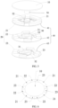
- the electronic device includes a first display 10, a transmission assembly 30, and at least two second displays 20.
- the first display 10 includes a first surface (not shown) used to display an image and a second surface (not shown) opposite to the first surface.
- the at least two second displays 20 are connected to the transmission assembly 30, and the transmission assembly 30 drives the at least two second displays 20 to move between first positions and second positions.
- each of the least two second displays 20 is covered by an orthographic projection of the first display 10 along a perpendicular direction of the second surface; or when the at least two second displays 20 are located at the second positions, at least two second displays 20 are located on a periphery of the first display 10, and abut against an outer peripheral wall of the first display 10.
- the second displays 20 of the electronic device can move between the first positions and the second positions when driven by the transmission assembly 30, to improve flexibility of a display of the electronic device, and solve the problem in the prior art that a display of an electronic device has a single structure.
- the transmission assembly 30 faces the second surface, that is, is located on a side of the first display 10 that is not used to display an image.
- the electronic device further includes a rotating shaft 50.
- the movement of the transmission assembly 30 being driven by the rotating shaft 50.
- the rotating shaft 50 is connected to the first display 10, and the transmission assembly 30 is rotatably connected to the first display 10 through the rotating shaft 50.
- the rotating shaft 50 is disposed on a center area of the second surface of the first display 10, and the rotating shaft 50 extends in a direction away from the second surface.
- the transmission assembly 30 may be sleeved on the rotating shaft 50, and rotation of the first display 10 drives the rotating shaft 50 and the transmission assembly 30 to rotate coaxially, so that the transmission assembly 30 drives the second displays 20 to move.
- a user may manually rotate the first display 10 to rotate the rotating shaft 50.
- the first display 10 covers the tray 40.
- a size of the tray 40 is less than or equal to a size of the first display 10, so that the tray 40 is not exposed to the outside of the first display 10, and when the second displays 20 are located at the first positions, the second displays 20 and the tray 40 are covered by the first display 10, to ensure beauty of appearance of the electronic device.
- the rotating shaft 50 and the transmission shaft 31 may run through the tray 40, and the tray 40 is sleeved on the rotating shaft 50 or the transmission shaft 31; or when there is one tray 40, the tray 40 may be connected to a housing of the electronic device, and when the transmission shaft 31 rotates, the tray 40 is fixed.
- a quantity of the first guiding structures 401 is the same as a quantity of the second guiding structures 201.
- the first guiding structures 401 and the second guiding structures 201 can guide movement of the second displays 20 and prevent displacement of movement of the second display 20, to guide the plurality of second displays 20 to move to the second positions to be on a same plane as the first display 10 and be stitched into an entire display screen together with the first display 10, for example, a round or square display screen.
- the first guiding structure 401 is a sliding part, and is optionally a roller
- the second guiding structure 201 is a guiding slot.
- the guiding slot includes a first side wall and a bottom surface, the bottom surface is an oblique surface, and a distance between a part of the bottom surface close to the transmission assembly 30 and the tray 40 is less than a distance between a part of the bottom surface away from the transmission assembly 30 and the tray 40.
- the bottom surface of the guiding slot is an oblique surface relative to the tray 40
- the bottom surface of the guiding grove includes a first end close to the transmission shaft 31 and a second end away from the transmission shaft 31, and the first end is closer to the tray 40 than the second end.
- the guiding slot is located on a side of the second display 20 facing the tray 40, and the roller is disposed on the tray 40, and contacts the bottom surface of the guiding slot.
- the tray 40 is fixed, and a position of the roller on the tray 40 is not changed. Therefore, when the second display 20 move from the first position to the second position, the guiding slot moves relative to the roller, and rolling of the roller exerts thrust on the guiding slot, to push the second display 20 to move towards the second position.
- first sub displays 21 and the second sub displays 22 are disposed alternately when being located at the second positions.
- each tray 40 carries a second display 20.
- the second displays are stitched into a ring and enclose the first display 10.
- a larger quantity of second displays 20 indicates that sizes of the second displays can be designed to be smaller, facilitating arrangement of the second displays 20 in the electronic device.
- the transmission assembly 30, the first guiding structures, and the second guiding structures may be designed in a manner in the embodiments of FIG. 1 to FIG. 4 , and details are not provided herein again.
Landscapes
- Engineering & Computer Science (AREA)
- Theoretical Computer Science (AREA)
- Computer Hardware Design (AREA)
- Physics & Mathematics (AREA)
- General Physics & Mathematics (AREA)
- Human Computer Interaction (AREA)
- General Engineering & Computer Science (AREA)
- Microelectronics & Electronic Packaging (AREA)
- Devices For Indicating Variable Information By Combining Individual Elements (AREA)
- Telephone Set Structure (AREA)
Claims (12)
- Elektronische Vorrichtung, die Folgendes umfasst: eine erste Anzeige (10), eine Übertragungsanordnung (30) und mindestens zwei Anzeigen zweiter Art (20), wobei die erste Anzeige (10) eine erste Oberfläche und eine zweite Oberfläche umfasst, die der ersten Oberfläche gegenüberliegt, die mindestens zwei zweiten Anzeigen (20) mit der Übertragungsanordnung (30) verbunden sind und die Übertragungsanordnung (30) die mindestens zwei zweiten Anzeigen (20) ansteuert, um sie zwischen ersten Positionen und zweiten Positionen zu bewegen, wobei,wenn die mindestens zwei zweiten Anzeigen (20) an den ersten Positionen angeordnet sind, mindestens ein Teil jeder der mindestens zwei zweiten Anzeigen (20) durch eine orthogonale Projektion der ersten Anzeige (10) entlang einer senkrechten Richtung der zweiten Oberfläche abgedeckt ist; oder, wenn die mindestens zwei zweiten Anzeigen (20) an den zweiten Positionen angeordnet sind, mindestens zwei Anzeigen zweiter Art (20) an einem Umfang der ersten Anzeige (10) angeordnet sind und an einer äußeren Umfangswand der ersten Anzeige (10) anliegen; wobei die elektronische Vorrichtung ferner eine rotierende Welle (50) umfasst, und die Getriebeanordnung (30) mit der rotierenden Welle (50) verbunden ist; wobeidie rotierende Welle (50) mit der ersten Anzeige (10) verbunden ist, und die rotierende Welle (50) in einem mittleren Bereich der zweiten Oberfläche angeordnet ist und sich in einer Richtung weg von der zweiten Oberfläche erstreckt, und die Übertragungsanordnung (30) drehbar mit der ersten Anzeige (10) durch die rotierende Welle (50) verbunden ist.
- Elektronische Vorrichtung nach Anspruch 1, ferner umfassend einen Antriebsmotor, wobei die Getriebeanordnung (30) und/oder die rotierende Welle (50) mit einem Antriebsmotor verbunden sind.
- Elektronische Vorrichtung nach Anspruch 1, wobei die Getriebeanordnung (30) eine Getriebewelle (31) und Getriebestangen (32) umfasst und die Getriebewelle (31) über die rotierende Welle (50) mit der ersten Anzeige (10) verbunden ist oder, für den Fall, dass die elektronische Vorrichtung ferner einen Antriebsmotor umfasst, die Übertragungswelle (31) und/oder die rotierende Welle (50) mit dem Antriebsmotor verbunden ist, ein Ende jedes der Übertragungsstangen (32) mit der Übertragungswelle (31) verbunden ist und ein anderes Ende jeder der Übertragungsstangen (32) mit einer zweiten Anzeige (20) verbunden ist.
- Elektronische Vorrichtung nach Anspruch 3, bei der die Übertragungswelle (31) auf der rotierenden Welle (50) gelagert ist, ein Ende jeder der Übertragungsstangen (32) an der Übertragungswelle (31) angelenkt ist und ein anderes Ende der Übertragungsstangen (32) an der zweiten Anzeige (20) angelenkt ist.
- Elektronische Vorrichtung nach Anspruch 1, ferner umfassend eine Schale (40), wobei die Schale (40) eine zweite Anzeige (20) trägt, eine erste Führungsstruktur (401) auf einer der ersten Anzeige (10) zugewandten Seite der Schale (40) angeordnet ist, eine zweite Führungsstruktur (201) auf der zweiten Anzeige (20) angeordnet ist und die erste Führungsstruktur (401) mit der zweiten Führungsstruktur (201) zusammenwirkt; und,
wenn sich die mindestens zwei zweiten Anzeigen (20) durch die ersten Führungsstrukturen (401) und die zweiten Führungsstrukturen (201) in die zweiten Positionen bewegen, befinden sich die mindestens zwei zweiten Anzeigen (20) und die erste Anzeige (10) auf derselben Ebene. - Elektronische Vorrichtung nach Anspruch 5, wobei die erste Führungsstruktur (401) ein Gleitteil ist, die zweite Führungsstruktur (201) ein Führungsschlitz ist, der Führungsschlitz eine erste Seitenwand und eine Bodenfläche umfasst, die Bodenfläche eine schräge Fläche ist und ein Abstand zwischen einem Teil der Bodenfläche nahe der Übertragungsanordnung (30) und der Schale(40) geringer ist als ein Abstand zwischen einem Teil der Bodenfläche entfernt von der Übertragungsanordnung (30) und der Schale (40).
- Elektronische Vorrichtung nach Anspruch 5, wobei mindestens zwei Schalen (40) vorhanden sind und die mindestens zwei Schalen (40) in der senkrechten Richtung der zweiten Oberfläche gestapelt sind.
- Elektronische Vorrichtung nach Anspruch 7, wobei die Anzahl der Schalen (40) der Anzahl der zweiten Anzeigen (20) entspricht; und/oder
zwei Anzeigen (40) vorhanden sind, und die mindestens zwei zweiten Anzeigen (20) mindestens eine erste Teilanzeige (21), die von einer Schale (40) getragen wird, und mindestens eine zweite Teilanzeige (22), die von der anderen Schale (40) getragen wird, umfassen. - Elektronische Vorrichtung nach Anspruch 7, wobei mindestens zwei erste Teilanzeigen (21) und mindestens zwei zweite Teilanzeigen (22) vorhanden sind und die ersten Teilanzeigen (21) und die zweiten Teilanzeigen (22) abwechselnd angeordnet sind, wenn sie sich an den zweiten Positionen befinden.
- Elektronische Vorrichtung nach Anspruch 8, wobei drei Schalen (40) vorhanden sind, die drei Schalen (40) eine erste Schale (41), eine zweite Schale (42) und eine dritte Schale (43) umfassen, und die mindestens zwei zweiten Anzeigen (20) mindestens eine erste Teilanzeige (21), die von der ersten Schale (41) getragen wird, mindestens eine zweite Teilanzeige (22), die von der zweiten Schale (42) getragen wird, und mindestens eine dritte Teilanzeige (23), die von der dritten Schale (43) getragen wird, umfassen.
- Elektronische Vorrichtung nach Anspruch 10, wobei vier erste Teilanzeigen (21), vier zweite Teilanzeigen (22) und vier dritte Teilanzeigen (23) vorhanden sind, und wenn die vier ersten Teilanzeigen (21), die vier zweiten Teilanzeigen (22) und die vier dritten Teilanzeigen (23) an den zweiten Positionen angeordnet sind, eine zweite Teilanzeige (22) und eine dritte Teilanzeige (23) zwischen zwei beliebigen benachbarten ersten Teilanzeigen (21) angeordnet sind, und eine dritte Teilanzeige (23) und eine erste Teilanzeige (21) zwischen zwei beliebigen benachbarten zweiten Teilanzeigen (22) angeordnet sind.
- Elektronische Vorrichtung nach Anspruch 1, wobei eine Fläche jeder der mindestens zwei zweiten Anzeigen (20) kleiner ist als eine Fläche der ersten Anzeige (10), und wenn die mindestens zwei zweiten Anzeigen (20) an den ersten Positionen angeordnet sind, die erste Anzeige (10) die mindestens zwei zweiten Anzeigen (20) in der senkrechten Richtung der zweiten Oberfläche abdeckt.
Applications Claiming Priority (2)
| Application Number | Priority Date | Filing Date | Title |
|---|---|---|---|
| CN201910645582.1A CN110426946B (zh) | 2019-07-17 | 2019-07-17 | 一种电子设备 |
| PCT/CN2020/100431 WO2021008404A1 (zh) | 2019-07-17 | 2020-07-06 | 电子设备 |
Publications (3)
| Publication Number | Publication Date |
|---|---|
| EP4002019A1 EP4002019A1 (de) | 2022-05-25 |
| EP4002019A4 EP4002019A4 (de) | 2022-08-31 |
| EP4002019B1 true EP4002019B1 (de) | 2025-04-16 |
Family
ID=68410756
Family Applications (1)
| Application Number | Title | Priority Date | Filing Date |
|---|---|---|---|
| EP20841567.9A Active EP4002019B1 (de) | 2019-07-17 | 2020-07-06 | Elektronische vorrichtung |
Country Status (5)
| Country | Link |
|---|---|
| US (1) | US12133345B2 (de) |
| EP (1) | EP4002019B1 (de) |
| CN (1) | CN110426946B (de) |
| ES (1) | ES3029358T3 (de) |
| WO (1) | WO2021008404A1 (de) |
Families Citing this family (3)
| Publication number | Priority date | Publication date | Assignee | Title |
|---|---|---|---|---|
| CN110426946B (zh) | 2019-07-17 | 2021-08-20 | 维沃移动通信有限公司 | 一种电子设备 |
| CN112987549A (zh) * | 2021-02-08 | 2021-06-18 | 维沃移动通信有限公司 | 穿戴设备和穿戴设备的控制方法 |
| CN114267262B (zh) * | 2021-12-29 | 2023-06-06 | 武汉天马微电子有限公司 | 一种显示装置及终端设备 |
Family Cites Families (29)
| Publication number | Priority date | Publication date | Assignee | Title |
|---|---|---|---|---|
| HRP20000212A2 (en) * | 2000-04-13 | 2001-12-31 | Nikolić Robert | A modular telecommunication and pda unit |
| EP1343058A1 (de) | 2002-03-08 | 2003-09-10 | Belal Establishments | Gebetszeitgeber |
| US20050164750A1 (en) * | 2004-01-22 | 2005-07-28 | Arima Communication Corp. | Mobile communication device with battery strap |
| EP1862872B8 (de) | 2005-03-25 | 2012-02-15 | Citizen Holdings Co., Ltd. | Elektronische einrichtung und display-steuerverfahren |
| US8082631B2 (en) * | 2007-06-19 | 2011-12-27 | Nokia Corporation | Folding mechanism for compact device |
| US20090104931A1 (en) * | 2007-10-17 | 2009-04-23 | Akina Chiang | Parallelogrammic foldable cellphone |
| US8947320B2 (en) * | 2008-09-08 | 2015-02-03 | Qualcomm Incorporated | Method for indicating location and direction of a graphical user interface element |
| US8803816B2 (en) * | 2008-09-08 | 2014-08-12 | Qualcomm Incorporated | Multi-fold mobile device with configurable interface |
| KR20100042149A (ko) * | 2008-10-15 | 2010-04-23 | 정세린 | 표시부 유동형 시계 |
| CN201569827U (zh) * | 2009-08-03 | 2010-09-01 | 中兴通讯股份有限公司南京分公司 | 一种lcd显示装置 |
| CN102540850B (zh) | 2010-12-24 | 2016-12-21 | 上海黄嘉历史文化传播有限公司 | 用太极图形显示时间的时间显示装置及其显示方法 |
| CN103064464B (zh) * | 2011-10-18 | 2015-08-19 | 宏碁股份有限公司 | 具有多屏幕的笔记本电脑 |
| CN103716428B (zh) * | 2013-12-30 | 2016-03-02 | 京东方科技集团股份有限公司 | 便携式显示装置 |
| CN204129444U (zh) | 2014-09-28 | 2015-01-28 | 联想(北京)有限公司 | 电子设备 |
| CN104483825B (zh) * | 2014-12-11 | 2017-01-25 | 深圳市华星光电技术有限公司 | 智能手表的表盘和智能手表 |
| CN105137743B (zh) * | 2015-10-15 | 2018-05-15 | 京东方科技集团股份有限公司 | 一种智能手表 |
| CN205451034U (zh) * | 2016-02-29 | 2016-08-10 | 联想(北京)有限公司 | 电子设备 |
| CN205608604U (zh) * | 2016-04-27 | 2016-09-28 | 北京灵铱科技有限公司 | 一种弹簧式无序折叠的三屏自动开合显示设备 |
| KR101861077B1 (ko) * | 2016-06-02 | 2018-06-05 | 주식회사 이랜텍 | 힌지 및 이를 구비하는 플렉서블 디스플레이 디바이스 |
| CN205845042U (zh) * | 2016-06-21 | 2016-12-28 | 北京灵铱科技有限公司 | 一种双丝杠式三屏自动开合显示设备 |
| CN106371509B (zh) * | 2016-08-19 | 2020-01-31 | 联想(北京)有限公司 | 一种电子设备 |
| WO2016203321A2 (en) * | 2016-10-18 | 2016-12-22 | Almuhairbi, Eida | Motorized foldable flexible display |
| CN106990706A (zh) | 2017-04-13 | 2017-07-28 | 韦慧芳 | 智能手表 |
| CN207817576U (zh) * | 2017-12-26 | 2018-09-04 | 比亚迪股份有限公司 | 三屏笔记本 |
| CN108535994B (zh) * | 2018-03-23 | 2019-11-22 | 飞亚达(集团)股份有限公司 | 一种时间显示方法 |
| US11071228B2 (en) * | 2018-09-26 | 2021-07-20 | Apple Inc. | Computing workstation with accessible in a rack environment |
| CN109782576B (zh) | 2018-12-30 | 2021-12-10 | 淮北中易光电科技有限公司 | 智能手表 |
| CN110426946B (zh) * | 2019-07-17 | 2021-08-20 | 维沃移动通信有限公司 | 一种电子设备 |
| KR102849262B1 (ko) * | 2019-10-16 | 2025-08-22 | 삼성전자주식회사 | 폴더블 디스플레이를 이용하여 화면을 제공하는 방법 및 이를 지원하기 위한 전자 장치 |
-
2019
- 2019-07-17 CN CN201910645582.1A patent/CN110426946B/zh active Active
-
2020
- 2020-07-06 ES ES20841567T patent/ES3029358T3/es active Active
- 2020-07-06 EP EP20841567.9A patent/EP4002019B1/de active Active
- 2020-07-06 WO PCT/CN2020/100431 patent/WO2021008404A1/zh not_active Ceased
-
2022
- 2022-01-11 US US17/573,515 patent/US12133345B2/en active Active
Also Published As
| Publication number | Publication date |
|---|---|
| EP4002019A1 (de) | 2022-05-25 |
| WO2021008404A1 (zh) | 2021-01-21 |
| US20220132691A1 (en) | 2022-04-28 |
| CN110426946B (zh) | 2021-08-20 |
| ES3029358T3 (en) | 2025-06-24 |
| EP4002019A4 (de) | 2022-08-31 |
| US12133345B2 (en) | 2024-10-29 |
| CN110426946A (zh) | 2019-11-08 |
Similar Documents
| Publication | Publication Date | Title |
|---|---|---|
| EP4002019B1 (de) | Elektronische vorrichtung | |
| US10876337B2 (en) | Sliding hinge and electronic device having the same | |
| US10817030B2 (en) | Portable information handling system flexible display with alternating slide support frame | |
| CN108924296B (zh) | 柔性屏滑动装置及终端设备 | |
| EP3731503A1 (de) | Mobiles endgerät mit flexibler anzeigevorrichtung | |
| KR20230014807A (ko) | 플렉서블 디스플레이를 포함하는 전자 장치 | |
| US11953942B2 (en) | Foldable electronic device having multiple screens | |
| US20230244278A1 (en) | Display module and display device | |
| EP4036897A1 (de) | Elektronische vorrichtung | |
| US20060056141A1 (en) | Portable electronic device | |
| EP4160351A1 (de) | Elektronische vorrichtung | |
| EP2685344B1 (de) | Zusammenklappbares elektronisches Gerät | |
| TW201605323A (zh) | 可折疊顯示裝置 | |
| US11775012B2 (en) | Foldable screen and electronic device | |
| KR101695206B1 (ko) | 화면확장형 휴대용 단말기 | |
| US11599157B2 (en) | Hinge module and electronic device | |
| WO2023109840A1 (zh) | 电子设备 | |
| CN110427072B (zh) | 一种电子设备 | |
| CN114006961A (zh) | 折叠装置及电子设备 | |
| CN114495699A (zh) | 柔性显示屏的支撑装置和终端设备 | |
| TW201504554A (zh) | 顯示裝置及其包含之顯示裝置基座 | |
| EP4697686A1 (de) | Klappmechanismus und elektronische vorrichtung | |
| CN114461023B (zh) | 电子设备 | |
| CN116044887B (zh) | 铰链机构及电子设备 | |
| CN110737310B (zh) | 一种电子设备 |
Legal Events
| Date | Code | Title | Description |
|---|---|---|---|
| STAA | Information on the status of an ep patent application or granted ep patent |
Free format text: STATUS: THE INTERNATIONAL PUBLICATION HAS BEEN MADE |
|
| PUAI | Public reference made under article 153(3) epc to a published international application that has entered the european phase |
Free format text: ORIGINAL CODE: 0009012 |
|
| STAA | Information on the status of an ep patent application or granted ep patent |
Free format text: STATUS: REQUEST FOR EXAMINATION WAS MADE |
|
| 17P | Request for examination filed |
Effective date: 20220131 |
|
| AK | Designated contracting states |
Kind code of ref document: A1 Designated state(s): AL AT BE BG CH CY CZ DE DK EE ES FI FR GB GR HR HU IE IS IT LI LT LU LV MC MK MT NL NO PL PT RO RS SE SI SK SM TR |
|
| A4 | Supplementary search report drawn up and despatched |
Effective date: 20220729 |
|
| RIC1 | Information provided on ipc code assigned before grant |
Ipc: G06F 1/16 20060101ALI20220725BHEP Ipc: G04G 17/04 20060101AFI20220725BHEP |
|
| DAV | Request for validation of the european patent (deleted) | ||
| DAX | Request for extension of the european patent (deleted) | ||
| GRAP | Despatch of communication of intention to grant a patent |
Free format text: ORIGINAL CODE: EPIDOSNIGR1 |
|
| STAA | Information on the status of an ep patent application or granted ep patent |
Free format text: STATUS: GRANT OF PATENT IS INTENDED |
|
| INTG | Intention to grant announced |
Effective date: 20241209 |
|
| GRAS | Grant fee paid |
Free format text: ORIGINAL CODE: EPIDOSNIGR3 |
|
| GRAA | (expected) grant |
Free format text: ORIGINAL CODE: 0009210 |
|
| STAA | Information on the status of an ep patent application or granted ep patent |
Free format text: STATUS: THE PATENT HAS BEEN GRANTED |
|
| AK | Designated contracting states |
Kind code of ref document: B1 Designated state(s): AL AT BE BG CH CY CZ DE DK EE ES FI FR GB GR HR HU IE IS IT LI LT LU LV MC MK MT NL NO PL PT RO RS SE SI SK SM TR |
|
| REG | Reference to a national code |
Ref country code: GB Ref legal event code: FG4D |
|
| REG | Reference to a national code |
Ref country code: CH Ref legal event code: EP Ref country code: DE Ref legal event code: R096 Ref document number: 602020049673 Country of ref document: DE |
|
| REG | Reference to a national code |
Ref country code: IE Ref legal event code: FG4D |
|
| REG | Reference to a national code |
Ref country code: NL Ref legal event code: FP |
|
| REG | Reference to a national code |
Ref country code: ES Ref legal event code: FG2A Ref document number: 3029358 Country of ref document: ES Kind code of ref document: T3 Effective date: 20250624 |
|
| PGFP | Annual fee paid to national office [announced via postgrant information from national office to epo] |
Ref country code: GB Payment date: 20250529 Year of fee payment: 6 |
|
| PGFP | Annual fee paid to national office [announced via postgrant information from national office to epo] |
Ref country code: NL Payment date: 20250613 Year of fee payment: 6 |
|
| PGFP | Annual fee paid to national office [announced via postgrant information from national office to epo] |
Ref country code: FR Payment date: 20250610 Year of fee payment: 6 |
|
| REG | Reference to a national code |
Ref country code: AT Ref legal event code: MK05 Ref document number: 1786153 Country of ref document: AT Kind code of ref document: T Effective date: 20250416 |
|
| PG25 | Lapsed in a contracting state [announced via postgrant information from national office to epo] |
Ref country code: FI Free format text: LAPSE BECAUSE OF FAILURE TO SUBMIT A TRANSLATION OF THE DESCRIPTION OR TO PAY THE FEE WITHIN THE PRESCRIBED TIME-LIMIT Effective date: 20250416 Ref country code: PT Free format text: LAPSE BECAUSE OF FAILURE TO SUBMIT A TRANSLATION OF THE DESCRIPTION OR TO PAY THE FEE WITHIN THE PRESCRIBED TIME-LIMIT Effective date: 20250818 |
|
| PGFP | Annual fee paid to national office [announced via postgrant information from national office to epo] |
Ref country code: ES Payment date: 20250805 Year of fee payment: 6 |
|
| PGFP | Annual fee paid to national office [announced via postgrant information from national office to epo] |
Ref country code: DE Payment date: 20250528 Year of fee payment: 6 |
|
| REG | Reference to a national code |
Ref country code: LT Ref legal event code: MG9D |
|
| PG25 | Lapsed in a contracting state [announced via postgrant information from national office to epo] |
Ref country code: NO Free format text: LAPSE BECAUSE OF FAILURE TO SUBMIT A TRANSLATION OF THE DESCRIPTION OR TO PAY THE FEE WITHIN THE PRESCRIBED TIME-LIMIT Effective date: 20250716 Ref country code: GR Free format text: LAPSE BECAUSE OF FAILURE TO SUBMIT A TRANSLATION OF THE DESCRIPTION OR TO PAY THE FEE WITHIN THE PRESCRIBED TIME-LIMIT Effective date: 20250717 |
|
| PG25 | Lapsed in a contracting state [announced via postgrant information from national office to epo] |
Ref country code: PL Free format text: LAPSE BECAUSE OF FAILURE TO SUBMIT A TRANSLATION OF THE DESCRIPTION OR TO PAY THE FEE WITHIN THE PRESCRIBED TIME-LIMIT Effective date: 20250416 |
|
| PGFP | Annual fee paid to national office [announced via postgrant information from national office to epo] |
Ref country code: IT Payment date: 20250623 Year of fee payment: 6 |
|
| PG25 | Lapsed in a contracting state [announced via postgrant information from national office to epo] |
Ref country code: BG Free format text: LAPSE BECAUSE OF FAILURE TO SUBMIT A TRANSLATION OF THE DESCRIPTION OR TO PAY THE FEE WITHIN THE PRESCRIBED TIME-LIMIT Effective date: 20250416 |
|
| PG25 | Lapsed in a contracting state [announced via postgrant information from national office to epo] |
Ref country code: HR Free format text: LAPSE BECAUSE OF FAILURE TO SUBMIT A TRANSLATION OF THE DESCRIPTION OR TO PAY THE FEE WITHIN THE PRESCRIBED TIME-LIMIT Effective date: 20250416 |
|
| PG25 | Lapsed in a contracting state [announced via postgrant information from national office to epo] |
Ref country code: AT Free format text: LAPSE BECAUSE OF FAILURE TO SUBMIT A TRANSLATION OF THE DESCRIPTION OR TO PAY THE FEE WITHIN THE PRESCRIBED TIME-LIMIT Effective date: 20250416 |
|
| PG25 | Lapsed in a contracting state [announced via postgrant information from national office to epo] |
Ref country code: RS Free format text: LAPSE BECAUSE OF FAILURE TO SUBMIT A TRANSLATION OF THE DESCRIPTION OR TO PAY THE FEE WITHIN THE PRESCRIBED TIME-LIMIT Effective date: 20250716 |
|
| PG25 | Lapsed in a contracting state [announced via postgrant information from national office to epo] |
Ref country code: IS Free format text: LAPSE BECAUSE OF FAILURE TO SUBMIT A TRANSLATION OF THE DESCRIPTION OR TO PAY THE FEE WITHIN THE PRESCRIBED TIME-LIMIT Effective date: 20250816 |
|
| PG25 | Lapsed in a contracting state [announced via postgrant information from national office to epo] |
Ref country code: LV Free format text: LAPSE BECAUSE OF FAILURE TO SUBMIT A TRANSLATION OF THE DESCRIPTION OR TO PAY THE FEE WITHIN THE PRESCRIBED TIME-LIMIT Effective date: 20250416 |
|
| PG25 | Lapsed in a contracting state [announced via postgrant information from national office to epo] |
Ref country code: DK Free format text: LAPSE BECAUSE OF FAILURE TO SUBMIT A TRANSLATION OF THE DESCRIPTION OR TO PAY THE FEE WITHIN THE PRESCRIBED TIME-LIMIT Effective date: 20250416 Ref country code: SM Free format text: LAPSE BECAUSE OF FAILURE TO SUBMIT A TRANSLATION OF THE DESCRIPTION OR TO PAY THE FEE WITHIN THE PRESCRIBED TIME-LIMIT Effective date: 20250416 |
|
| PG25 | Lapsed in a contracting state [announced via postgrant information from national office to epo] |
Ref country code: CZ Free format text: LAPSE BECAUSE OF FAILURE TO SUBMIT A TRANSLATION OF THE DESCRIPTION OR TO PAY THE FEE WITHIN THE PRESCRIBED TIME-LIMIT Effective date: 20250416 |
|
| PG25 | Lapsed in a contracting state [announced via postgrant information from national office to epo] |
Ref country code: EE Free format text: LAPSE BECAUSE OF FAILURE TO SUBMIT A TRANSLATION OF THE DESCRIPTION OR TO PAY THE FEE WITHIN THE PRESCRIBED TIME-LIMIT Effective date: 20250416 |
|
| PG25 | Lapsed in a contracting state [announced via postgrant information from national office to epo] |
Ref country code: RO Free format text: LAPSE BECAUSE OF FAILURE TO SUBMIT A TRANSLATION OF THE DESCRIPTION OR TO PAY THE FEE WITHIN THE PRESCRIBED TIME-LIMIT Effective date: 20250416 Ref country code: SK Free format text: LAPSE BECAUSE OF FAILURE TO SUBMIT A TRANSLATION OF THE DESCRIPTION OR TO PAY THE FEE WITHIN THE PRESCRIBED TIME-LIMIT Effective date: 20250416 |
|
| PLBE | No opposition filed within time limit |
Free format text: ORIGINAL CODE: 0009261 |
|
| STAA | Information on the status of an ep patent application or granted ep patent |
Free format text: STATUS: NO OPPOSITION FILED WITHIN TIME LIMIT |