EP4001820A1 - Oscillating heat pipe - Google Patents
Oscillating heat pipe Download PDFInfo
- Publication number
- EP4001820A1 EP4001820A1 EP20208922.3A EP20208922A EP4001820A1 EP 4001820 A1 EP4001820 A1 EP 4001820A1 EP 20208922 A EP20208922 A EP 20208922A EP 4001820 A1 EP4001820 A1 EP 4001820A1
- Authority
- EP
- European Patent Office
- Prior art keywords
- heat pipe
- oscillating heat
- region
- bendable
- electronic device
- Prior art date
- Legal status (The legal status is an assumption and is not a legal conclusion. Google has not performed a legal analysis and makes no representation as to the accuracy of the status listed.)
- Pending
Links
- 229920000642 polymer Polymers 0.000 claims abstract description 32
- 239000012530 fluid Substances 0.000 claims description 72
- 239000007789 gas Substances 0.000 claims description 9
- 239000000463 material Substances 0.000 claims description 9
- 230000000694 effects Effects 0.000 claims description 5
- 239000002184 metal Substances 0.000 claims description 4
- PXGOKWXKJXAPGV-UHFFFAOYSA-N Fluorine Chemical compound FF PXGOKWXKJXAPGV-UHFFFAOYSA-N 0.000 claims description 3
- 229910052731 fluorine Inorganic materials 0.000 claims description 3
- 239000011737 fluorine Substances 0.000 claims description 3
- 230000003993 interaction Effects 0.000 claims description 3
- 229910001092 metal group alloy Inorganic materials 0.000 claims description 3
- 238000001816 cooling Methods 0.000 abstract description 3
- 238000005452 bending Methods 0.000 description 10
- 238000012546 transfer Methods 0.000 description 9
- 230000008878 coupling Effects 0.000 description 5
- 238000010168 coupling process Methods 0.000 description 5
- 238000005859 coupling reaction Methods 0.000 description 5
- 239000007788 liquid Substances 0.000 description 5
- 230000005484 gravity Effects 0.000 description 4
- 241000237858 Gastropoda Species 0.000 description 3
- 230000007480 spreading Effects 0.000 description 3
- 238000003892 spreading Methods 0.000 description 3
- IJGRMHOSHXDMSA-UHFFFAOYSA-N Atomic nitrogen Chemical compound N#N IJGRMHOSHXDMSA-UHFFFAOYSA-N 0.000 description 2
- OKTJSMMVPCPJKN-UHFFFAOYSA-N Carbon Chemical compound [C] OKTJSMMVPCPJKN-UHFFFAOYSA-N 0.000 description 2
- 238000009833 condensation Methods 0.000 description 2
- 230000005494 condensation Effects 0.000 description 2
- 238000009826 distribution Methods 0.000 description 2
- 229920005558 epichlorohydrin rubber Polymers 0.000 description 2
- 229910002804 graphite Inorganic materials 0.000 description 2
- 239000010439 graphite Substances 0.000 description 2
- MSSNHSVIGIHOJA-UHFFFAOYSA-N pentafluoropropane Chemical compound FC(F)CC(F)(F)F MSSNHSVIGIHOJA-UHFFFAOYSA-N 0.000 description 2
- 229920001084 poly(chloroprene) Polymers 0.000 description 2
- 239000003351 stiffener Substances 0.000 description 2
- 239000000126 substance Substances 0.000 description 2
- 230000001133 acceleration Effects 0.000 description 1
- 239000000853 adhesive Substances 0.000 description 1
- 230000001070 adhesive effect Effects 0.000 description 1
- QVGXLLKOCUKJST-UHFFFAOYSA-N atomic oxygen Chemical compound [O] QVGXLLKOCUKJST-UHFFFAOYSA-N 0.000 description 1
- 230000004888 barrier function Effects 0.000 description 1
- 230000015572 biosynthetic process Effects 0.000 description 1
- 238000009529 body temperature measurement Methods 0.000 description 1
- 238000009835 boiling Methods 0.000 description 1
- 230000009172 bursting Effects 0.000 description 1
- 125000000484 butyl group Chemical group [H]C([*])([H])C([H])([H])C([H])([H])C([H])([H])[H] 0.000 description 1
- 239000000919 ceramic Substances 0.000 description 1
- 230000008859 change Effects 0.000 description 1
- 230000001419 dependent effect Effects 0.000 description 1
- 238000009792 diffusion process Methods 0.000 description 1
- 238000001704 evaporation Methods 0.000 description 1
- 230000008020 evaporation Effects 0.000 description 1
- 238000010438 heat treatment Methods 0.000 description 1
- 238000004519 manufacturing process Methods 0.000 description 1
- 238000000034 method Methods 0.000 description 1
- 238000012986 modification Methods 0.000 description 1
- 230000004048 modification Effects 0.000 description 1
- 229910052757 nitrogen Inorganic materials 0.000 description 1
- 230000010355 oscillation Effects 0.000 description 1
- 239000001301 oxygen Substances 0.000 description 1
- 229910052760 oxygen Inorganic materials 0.000 description 1
- 239000011295 pitch Substances 0.000 description 1
- 229920001296 polysiloxane Polymers 0.000 description 1
- 230000008569 process Effects 0.000 description 1
- 238000012545 processing Methods 0.000 description 1
- 230000000717 retained effect Effects 0.000 description 1
- 239000007787 solid Substances 0.000 description 1
- -1 surface tension Substances 0.000 description 1
- 238000010792 warming Methods 0.000 description 1
Images


Classifications
-
- H—ELECTRICITY
- H05—ELECTRIC TECHNIQUES NOT OTHERWISE PROVIDED FOR
- H05K—PRINTED CIRCUITS; CASINGS OR CONSTRUCTIONAL DETAILS OF ELECTRIC APPARATUS; MANUFACTURE OF ASSEMBLAGES OF ELECTRICAL COMPONENTS
- H05K7/00—Constructional details common to different types of electric apparatus
- H05K7/20—Modifications to facilitate cooling, ventilating, or heating
- H05K7/2029—Modifications to facilitate cooling, ventilating, or heating using a liquid coolant with phase change in electronic enclosures
- H05K7/20336—Heat pipes, e.g. wicks or capillary pumps
-
- F—MECHANICAL ENGINEERING; LIGHTING; HEATING; WEAPONS; BLASTING
- F28—HEAT EXCHANGE IN GENERAL
- F28D—HEAT-EXCHANGE APPARATUS, NOT PROVIDED FOR IN ANOTHER SUBCLASS, IN WHICH THE HEAT-EXCHANGE MEDIA DO NOT COME INTO DIRECT CONTACT
- F28D15/00—Heat-exchange apparatus with the intermediate heat-transfer medium in closed tubes passing into or through the conduit walls ; Heat-exchange apparatus employing intermediate heat-transfer medium or bodies
- F28D15/02—Heat-exchange apparatus with the intermediate heat-transfer medium in closed tubes passing into or through the conduit walls ; Heat-exchange apparatus employing intermediate heat-transfer medium or bodies in which the medium condenses and evaporates, e.g. heat pipes
- F28D15/0266—Heat-exchange apparatus with the intermediate heat-transfer medium in closed tubes passing into or through the conduit walls ; Heat-exchange apparatus employing intermediate heat-transfer medium or bodies in which the medium condenses and evaporates, e.g. heat pipes with separate evaporating and condensing chambers connected by at least one conduit; Loop-type heat pipes; with multiple or common evaporating or condensing chambers
-
- F—MECHANICAL ENGINEERING; LIGHTING; HEATING; WEAPONS; BLASTING
- F28—HEAT EXCHANGE IN GENERAL
- F28D—HEAT-EXCHANGE APPARATUS, NOT PROVIDED FOR IN ANOTHER SUBCLASS, IN WHICH THE HEAT-EXCHANGE MEDIA DO NOT COME INTO DIRECT CONTACT
- F28D15/00—Heat-exchange apparatus with the intermediate heat-transfer medium in closed tubes passing into or through the conduit walls ; Heat-exchange apparatus employing intermediate heat-transfer medium or bodies
- F28D15/02—Heat-exchange apparatus with the intermediate heat-transfer medium in closed tubes passing into or through the conduit walls ; Heat-exchange apparatus employing intermediate heat-transfer medium or bodies in which the medium condenses and evaporates, e.g. heat pipes
- F28D15/0241—Heat-exchange apparatus with the intermediate heat-transfer medium in closed tubes passing into or through the conduit walls ; Heat-exchange apparatus employing intermediate heat-transfer medium or bodies in which the medium condenses and evaporates, e.g. heat pipes the tubes being flexible
-
- F—MECHANICAL ENGINEERING; LIGHTING; HEATING; WEAPONS; BLASTING
- F28—HEAT EXCHANGE IN GENERAL
- F28D—HEAT-EXCHANGE APPARATUS, NOT PROVIDED FOR IN ANOTHER SUBCLASS, IN WHICH THE HEAT-EXCHANGE MEDIA DO NOT COME INTO DIRECT CONTACT
- F28D15/00—Heat-exchange apparatus with the intermediate heat-transfer medium in closed tubes passing into or through the conduit walls ; Heat-exchange apparatus employing intermediate heat-transfer medium or bodies
- F28D15/02—Heat-exchange apparatus with the intermediate heat-transfer medium in closed tubes passing into or through the conduit walls ; Heat-exchange apparatus employing intermediate heat-transfer medium or bodies in which the medium condenses and evaporates, e.g. heat pipes
- F28D15/0275—Arrangements for coupling heat-pipes together or with other structures, e.g. with base blocks; Heat pipe cores
-
- F—MECHANICAL ENGINEERING; LIGHTING; HEATING; WEAPONS; BLASTING
- F28—HEAT EXCHANGE IN GENERAL
- F28D—HEAT-EXCHANGE APPARATUS, NOT PROVIDED FOR IN ANOTHER SUBCLASS, IN WHICH THE HEAT-EXCHANGE MEDIA DO NOT COME INTO DIRECT CONTACT
- F28D15/00—Heat-exchange apparatus with the intermediate heat-transfer medium in closed tubes passing into or through the conduit walls ; Heat-exchange apparatus employing intermediate heat-transfer medium or bodies
- F28D15/02—Heat-exchange apparatus with the intermediate heat-transfer medium in closed tubes passing into or through the conduit walls ; Heat-exchange apparatus employing intermediate heat-transfer medium or bodies in which the medium condenses and evaporates, e.g. heat pipes
- F28D15/0283—Means for filling or sealing heat pipes
-
- F—MECHANICAL ENGINEERING; LIGHTING; HEATING; WEAPONS; BLASTING
- F28—HEAT EXCHANGE IN GENERAL
- F28D—HEAT-EXCHANGE APPARATUS, NOT PROVIDED FOR IN ANOTHER SUBCLASS, IN WHICH THE HEAT-EXCHANGE MEDIA DO NOT COME INTO DIRECT CONTACT
- F28D15/00—Heat-exchange apparatus with the intermediate heat-transfer medium in closed tubes passing into or through the conduit walls ; Heat-exchange apparatus employing intermediate heat-transfer medium or bodies
- F28D15/02—Heat-exchange apparatus with the intermediate heat-transfer medium in closed tubes passing into or through the conduit walls ; Heat-exchange apparatus employing intermediate heat-transfer medium or bodies in which the medium condenses and evaporates, e.g. heat pipes
- F28D15/06—Control arrangements therefor
-
- G—PHYSICS
- G06—COMPUTING; CALCULATING OR COUNTING
- G06F—ELECTRIC DIGITAL DATA PROCESSING
- G06F1/00—Details not covered by groups G06F3/00 - G06F13/00 and G06F21/00
- G06F1/16—Constructional details or arrangements
- G06F1/1613—Constructional details or arrangements for portable computers
- G06F1/1615—Constructional details or arrangements for portable computers with several enclosures having relative motions, each enclosure supporting at least one I/O or computing function
- G06F1/1616—Constructional details or arrangements for portable computers with several enclosures having relative motions, each enclosure supporting at least one I/O or computing function with folding flat displays, e.g. laptop computers or notebooks having a clamshell configuration, with body parts pivoting to an open position around an axis parallel to the plane they define in closed position
-
- G—PHYSICS
- G06—COMPUTING; CALCULATING OR COUNTING
- G06F—ELECTRIC DIGITAL DATA PROCESSING
- G06F1/00—Details not covered by groups G06F3/00 - G06F13/00 and G06F21/00
- G06F1/16—Constructional details or arrangements
- G06F1/1613—Constructional details or arrangements for portable computers
- G06F1/1633—Constructional details or arrangements of portable computers not specific to the type of enclosures covered by groups G06F1/1615 - G06F1/1626
- G06F1/1675—Miscellaneous details related to the relative movement between the different enclosures or enclosure parts
- G06F1/1683—Miscellaneous details related to the relative movement between the different enclosures or enclosure parts for the transmission of signal or power between the different housings, e.g. details of wired or wireless communication, passage of cabling
-
- G—PHYSICS
- G06—COMPUTING; CALCULATING OR COUNTING
- G06F—ELECTRIC DIGITAL DATA PROCESSING
- G06F1/00—Details not covered by groups G06F3/00 - G06F13/00 and G06F21/00
- G06F1/16—Constructional details or arrangements
- G06F1/20—Cooling means
- G06F1/203—Cooling means for portable computers, e.g. for laptops
-
- H—ELECTRICITY
- H05—ELECTRIC TECHNIQUES NOT OTHERWISE PROVIDED FOR
- H05K—PRINTED CIRCUITS; CASINGS OR CONSTRUCTIONAL DETAILS OF ELECTRIC APPARATUS; MANUFACTURE OF ASSEMBLAGES OF ELECTRICAL COMPONENTS
- H05K7/00—Constructional details common to different types of electric apparatus
- H05K7/20—Modifications to facilitate cooling, ventilating, or heating
- H05K7/2029—Modifications to facilitate cooling, ventilating, or heating using a liquid coolant with phase change in electronic enclosures
- H05K7/20327—Accessories for moving fluid, for connecting fluid conduits, for distributing fluid or for preventing leakage, e.g. pumps, tanks or manifolds
-
- H—ELECTRICITY
- H05—ELECTRIC TECHNIQUES NOT OTHERWISE PROVIDED FOR
- H05K—PRINTED CIRCUITS; CASINGS OR CONSTRUCTIONAL DETAILS OF ELECTRIC APPARATUS; MANUFACTURE OF ASSEMBLAGES OF ELECTRICAL COMPONENTS
- H05K7/00—Constructional details common to different types of electric apparatus
- H05K7/20—Modifications to facilitate cooling, ventilating, or heating
- H05K7/20954—Modifications to facilitate cooling, ventilating, or heating for display panels
- H05K7/2099—Liquid coolant with phase change
-
- F—MECHANICAL ENGINEERING; LIGHTING; HEATING; WEAPONS; BLASTING
- F28—HEAT EXCHANGE IN GENERAL
- F28F—DETAILS OF HEAT-EXCHANGE AND HEAT-TRANSFER APPARATUS, OF GENERAL APPLICATION
- F28F2225/00—Reinforcing means
- F28F2225/04—Reinforcing means for conduits
-
- F—MECHANICAL ENGINEERING; LIGHTING; HEATING; WEAPONS; BLASTING
- F28—HEAT EXCHANGE IN GENERAL
- F28F—DETAILS OF HEAT-EXCHANGE AND HEAT-TRANSFER APPARATUS, OF GENERAL APPLICATION
- F28F2280/00—Mounting arrangements; Arrangements for facilitating assembling or disassembling of heat exchanger parts
- F28F2280/10—Movable elements, e.g. being pivotable
- F28F2280/105—Movable elements, e.g. being pivotable with hinged connections
Definitions
- Examples of the disclosure relate to oscillating heat pipes. Some relate to oscillating heat pipes for use in bendable electronic devices.
- Hinged or otherwise bendable electronic devices are known. Such devices comprise components such as processors which generate unwanted levels of heat. Therefore, components that enable distribution of this heat are useful.
- an oscillating heat pipe comprising: at least one condenser region configured to be positioned in a first portion of a bendable electronic device; at least one evaporator region configured to be positioned in a second portion of a bendable electronic device; and at least one bendable region provided between the condenser region and the evaporator region and configured to extend across a hinge of a bendable electronic device wherein the at least one bendable region comprises a polymer tubing supported by a flexible helical support structure.
- the flexible helical support structure may comprise at least one of; metal, metal alloy, polymer.
- the evaporator region may be configured to be thermally coupled to at least one of; an electronic component, a vapour chamber, a heat spreader, a solid-state heat spreader, a heat pipe.
- the at least one condenser region may be configured to be thermally coupled to at least one of; a heat spreader, a vapour chamber.
- Working fluid within the oscillating heat pipe may have a confinement number less than one.
- Working fluid within the oscillating heat pipe may comprise fluorine.
- Working fluid within the oscillating heat pipe may have a vapour pressure high enough to reduce effects of ingress of non-condensable gases into the oscillating heat pipe.
- the at least one bendable region of the oscillating heat pipe may be formed from a polymer selected to reduce interaction with working fluid in the oscillating heat pipe.
- the condenser region and the evaporator region of the oscillating heat pipe may comprise rigid materials.
- the oscillating heat pipe may comprise at least one reservoir coupled to the oscillating heat pipe and configured to store working fluid for refilling the oscillating heat pipe.
- the at least one sensor configured to sense a filling level of the working fluid within the oscillating heat pipe and at least one controller configured to control refilling of the oscillating heat pipe from the reservoir based on a signal from the at least one sensor.
- the first portion of the bendable electronic device may be a rigid portion and the second portion of the bendable electronic device may be a rigid portion and the bendable region of the oscillating heat pipe may be provided across a hinge between the two rigid portions.
- the first portion of the bendable electronic device may comprise a display.
- the second portion of the bendable electronic device may comprise at least one of; battery, processor.
- a bendable electronic device comprising one or more oscillating heat pipes as described in any preceding paragraph.
- Examples of the disclosure relate to an oscillating heat pipe 101 that is configured for use in a hinged or otherwise bendable electronic device 201.
- the oscillating heat pipe 101 comprises at least one bendable region that is configured to extend across a hinge of the bendable electronic device.
- Fig. 1 schematically shows an oscillating heat pipe 101.
- the oscillating heat pipe 101 comprises a condenser region 103, an evaporator region 105 and an adiabatic section 107.
- the evaporator region 105 comprises any means for transferring heat from a heat source into working fluid within the oscillating heat pipe 101.
- the evaporator region 105 is thermally coupled to a heat source.
- the heat source could be an electronic component that generates unwanted heat during use of a bendable electronic device such as a battery or processing unit.
- the heat source could be a vapour chamber comprising a wick structure or heat pipe that could be thermally coupled between the oscillating heat pipe 101 and one or more electronic components.
- the condenser region 103 comprises any means for transferring heat out of the working fluid within the oscillating heat pipe 101.
- the condenser region 103 is thermally coupled to a heat sink, a vapour chamber or any other suitable type of means for transferring heat out of the working fluid.
- the oscillating heat pipe 101 is configured in a meandering or serpentine configuration comprising a plurality of bends.
- a first plurality of bends are located in the evaporator region 105 and a second plurality of bends are located in the condenser region 103.
- a first plurality of bends are located in the evaporator region 105
- a second plurality of bends are located in the condenser region 103.
- three U-shaped bends are shown in the evaporator region 105 and two U-shaped bends are shown in the condenser region 103.
- Other configurations and numbers of bends could be used in other examples of the disclosure.
- the meandering or serpentine configuration is configured so that the working fluid within the oscillating heat pipe 101 is alternately heated in the evaporator region 105 and cooled in the condenser region 103 of the oscillating heat pipe 101.
- the oscillating heat pipe 101 forms a closed loop.
- Other types of oscillating heat pipe 101 could be used in other examples of the disclosure.
- the oscillating heat pipe 101 has a diameter that is small enough to enable liquid slugs 109 and vapour plugs 111 to be formed within the working fluid.
- the diameter of the oscillating heat pipe 101 that enables the formation of liquid slugs 109 and vapour plugs 111 will depend upon the type of working fluid that is used and the properties of the working fluid such as surface tension, liquid density, vapour density or any other suitable property.
- an adiabatic section 107 is provided between the evaporator region 105 and the condenser region 103.
- the adiabatic section 107 extends between the bends in the condenser region 103 and the bends in the evaporator region 105.
- the adiabatic section 107 ensures that heat that is transferred into the working fluid in the evaporator region 105 is retained within the oscillating heat pipe 101 until the working fluid reaches the condenser region 103.
- the oscillating heat pipe 101 does not comprise an adiabatic section 107. Whether or not the oscillating heat pipe 101 comprises an adiabatic section 107 can depend on the application and system geometry of the oscillating heat pipe 101 and any other suitable factors.
- the oscillating heat pipe 101 does not use a wick structure and so can be simple to manufacture and can be configured to transfer more heat compared to a heat pipe or a vapour chamber comprising a wick structure.
- the oscillating heat pipe 101 is configured so that it can function in any orientation. That is, the movement of the fluid within the oscillating heat pipe 101 is not dependent upon gravity. This makes the oscillating heat pipe 101 suitable for use in portable electronic devices which could be used in different orientations.
- Figs. 2A to 2C show an example of a bendable electronic device 201 that could comprise one or more oscillating heat pipes 101 according to examples of the disclosure.
- Fig. 2A shows a front view of the bendable electronic device 201 in an unfolded configuration
- Fig. 2B shows a side view of the bendable electronic device 201 in an unfolded configuration
- Fig. 2C shows an end view of the bendable electronic device 201 in a folded configuration.
- the bendable electronic device 201 can be a portable electronic device such as a mobile phone, tablet, laptop or any other suitable electronic device.
- the bendable electronic device 201 can be used for wireless communications or for any other suitable purpose.
- the bendable electronic device 201 comprises a rigid central portion 209 and two rigid end portions 211.
- the rigid end portions 211 are coupled to the sides of the rigid central portion 209 via hinges 213.
- the rigid portions 209, 211 are rigid in that they cannot be easily deformed by a user applying normal forces.
- the rigid portions 209, 211 do not bend during normal use of the bendable electronic device 201.
- the rigid portions 209, 211 can house electronic components which enable the bendable electronic device 201 to function.
- the rigid portions 209, 211 can house electronic components that are not flexible and/or that could be damaged if they were bent or otherwise deformed.
- the hinges 213 can comprise any means that enable the rigid end portions 211 to be moved between folded and unfolded configurations.
- the hinges 213 In the unfolded configurations the hinges 213 are opened and the rigid end portions 211 are positioned adjacent to the rigid central portion 209 so that a surface of the rigid central portion 209 forms a substantially planar surface with the surfaces of the rigid end portions 211.
- the hinges 213 In the folded configuration the hinges 213 are closed and the rigid end portions 211 are provided overlaying the surface of the rigid central portion 209 so that the rigid end portions 211, at least partially, covers the surface of the rigid central portion 209.
- the hinges 213 could be configured so that in the folded configuration the rigid end portions 211 are positioned underneath the rigid central portion 209 rather than overlaying the rigid central portion 209.
- the bendable electronic device 201 comprises three different rigid portions 209, 211 and two hinges 213 between the different rigid portions.
- the bendable electronic device 201 could comprise a different number of rigid portions.
- the bendable electronic device 201 could comprise two rigid portions with a hinge between them or could comprise more than three rigid portions.
- the rigid portions 209, 211 can house any suitable electronic components.
- a processor unit 203 and a power source 205 such as a battery, are positioned in each of the rigid end portions 211 of the bendable electronic device 201.
- a display 207 is provided in the rigid central portion 209. Interconnects can be provided between the electronic components in the respective rigid portions 209, 211 of the bendable electronic device 201. This can enable control signals from the processor units 203 to be exchanged with the display 207 and can enable power from the power source 205 to be provided to the display 207.
- the bendable electronic device 201 When the bendable electronic device 201 is in use the components in the rigid end portions 211 such as the processor units 203 the power source 205 can generate unwanted heat.
- the central rigid portion 209 has a larger surface area that can be used for heat rejection. Therefore in examples of the disclosure an oscillating heat pipe 101 is provided which can transfer heat from the electronic components 203, 205 in the rigid end portions 211 to a heat sink in the central rigid portion 209.
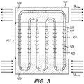
- Fig. 3 schematically shows an oscillating heat pipe 101 that can be used in a bendable electronic device 201.
- the oscillating heat pipe 101 could be used in a bendable electronic device 201 as shown in Figs. 2A to 2C or any other bendable electronic device 201 comprising two or more rigid portions 209, 211 and a hinge 213.
- the oscillating heat pipe 101 comprises a condenser region 103, an evaporator region 105 and a bendable region 301.
- the condenser region 103 is thermally coupled to a heat sink to allow for heat transfer out of the oscillating heat pipe 101.
- the heat sink could be a heat spreader, a vapour chamber or any other suitable means for removing heat from the oscillating heat pipe 101.
- the condenser region 103 is configured to be positioned in a first portion of a bendable electronic device 201.
- the condenser region 103 could be positioned within the rigid central portion 209 of the bendable electronic device 201 shown in Figs. 2A to 2C .
- one or more heat sinks could be provided within the rigid central portion 209.
- the evaporator region 105 is thermally coupled to one or more heat sources to allow for heat transfer into the oscillating heat pipe 101.
- the heat source could be one or more electronic components, one or more vapour chambers or any other suitable source of heat.
- the evaporator region 105 could be thermally coupled to a single heat source. In other examples the evaporator region 105 could be thermally coupled to a plurality of different heat sources.
- the evaporator region 105 is configured to be positioned in second portion of a bendable electronic device 201.
- the second portion of the bendable electronic device 201 is a different portion to the first portion in which the condenser region 103 is located.
- the evaporator region 105 could be positioned within either of the rigid end portions 211 of the bendable electronic device 201 shown in Figs. 2A to 2C .
- the evaporator region 105 could be thermally coupled to the processor units 203 and/or power sources 205.
- the oscillating heat pipe 101 also comprises a bendable region 301.
- the bendable region 301 in indicated in the dashed lines in Fig. 3 .
- the bendable region 301 is provided between the condenser region 103 and the evaporator region 105. In the example shown in Fig. 3 the bendable region 301 is shown in the dashed lines.
- the bendable region 301 can be provided within the adiabatic section 107 of the oscillating heat pipe 101.
- the bendable region 301 of the oscillating heat pipe 101 is configured to extend a across a hinge 213 of the bendable electronic device 201.
- the bendable region 301 of the oscillating heat pipe 101 is located across the hinge so that the bendable region 301 can bend and straighten as the hinge 213 is opened and closed.
- the oscillating heat pipe 101 is shown in a straight or unfolded configuration. It is to be appreciated that the bendable region 301 allows for the bending of the oscillating heat pipe 101 so that, during use, the bending of the bendable region 301 allows for movement of the condenser region 103 relative to the evaporator region 105.
- the bendable region 301 comprises a flexible structure.
- the bendable region 301 can comprise a polymer tubing 303 supported by a flexible helical support structure 305.
- An example of the polymer tubing 303 and flexible helical support structure 305 that can be used is shown in more detail in Figs. 6A to 6B .
- the bendable region 301 of the oscillating heat pipe 101 can be formed from flexible materials such as a polymer while the evaporator region 105 and the condenser region 103 can comprise rigid materials. This can enable the bendable region 301 of the oscillating heat pipe 101 to be folded and unfolded during use while the rigid condenser region 103 and evaporator region 105 do not bend or otherwise deform during use.
- the rigid materials that are used for the evaporator region 105 and the condenser region 103 can be selected based on heat transfer properties so as to ensure good heat transfer between the oscillating heat pipe 101 and the components of the bendable electronic device 201.
- the rigid evaporator region 105 can also function as a stiffener to help to reduce bending of portions of the electronic device 201. For example, it could help to reduce bending of a display or other similar components.
- the different materials for the different sections of the oscillating heat pipe 101 can be joined together using any suitable means.
- a bayonet connection or other mechanical type of connection could be used.
- an adhesive or other chemical connection could be used.
- the join between the different sections are sufficiently strong with respect to the internal pressure of the working fluid within the oscillating heat pipe 101 and the axial tensile forces that are generated when the oscillating heat pipe 101 is folded and unfolded.
- the join can be located within one of the rigid portions 209, 211 of the bendable electronic device so as to reduce forces on the join when the bendable electronic device 201 is opened and closed.
- Fig. 4 shows example oscillating heat pipes 101 in a bendable electronic device 201.
- Fig. 4 shows part of the bendable electronic device 201 as shown in Figs. 2A to 2C .
- part of the central rigid portion 209 and part of a rigid end portion 211 are shown together with the hinge 213 that connects the rigid portions 209, 211.
- oscillating heat pipes 101 could be provided in the other rigid end portion 211.
- other arrangements of oscillating heat pipes 101 could be used in other example bendable electronic devices 201.
- a first oscillating heat pipe 101 is shown with an evaporator region 105 located adjacent to the processor unit 203 so that heat from the processor unit 203 can be transferred into the working fluid in the evaporator region 105.
- a second oscillating heat pipe 101 is shown with an evaporator region 105 located adjacent to the power source 205 so that heat from the power source can be transferred into the working fluid in the evaporator region 105 of the second oscillating heat pipe 101.
- the oscillating heat pipes 101 can be thermally connected to heat spreaders such as vapour chambers, heat pipes, solid state spreaders or other suitable means.
- the heat spreaders could comprise a graphite sheet or thermally conductive metal or ceramic or any other suitable means.
- the evaporator regions 105 are located on the rigid end portion 211 they do not bend or otherwise deform and the bendable electronic device 201 is moved between a folded and unfolded configuration. Therefore the evaporator regions 105 can comprise rigid materials.
- the bendable regions 301 of the oscillating heat pipes 101 extend over the hinge 213 so that when the hinge 213 is opened and closed the bendable region 301 moves between an unfolded and folded configuration.
- the bendable electronic device 201 is shown in an unfolded configuration in which the rigid end portion 211 is positioned adjacent to the central rigid portion 209.
- the bendable region 301 of the oscillating heat pipe 101 is therefore also provided in an unfolded configuration.
- the condenser regions 103 of the oscillating heat pipes 101 are provided on the central rigid portion 209.
- the condenser regions 103 can be coupled to heat sinks, vapour chambers, heat pipes or any other suitable means for transferring heat out of the oscillating heat pipe 101.
- the heat sink could comprise a fixed heat spreader such as a metallic structure, a graphite sheet or any other suitable heat spreading means.
- the first oscillating heat pipe 101 comprises a plurality of condenser regions 103.
- the plurality of condenser regions 103 are spread across the central rigid portion 209. This enables a larger surface area to be used to dissipate the heat and can enable the heat to be transferred out of the oscillating heat pipe 101 more effectively.
- the second oscillating heat pipe 101 can comprise condenser regions 103 that are in different locations to the condenser regions 103 of the first oscillating heat pipe 101. This can enable the heat sinks that are used for the second oscillating heat pipe 101 to be spread out from the heat sinks that are used for the first oscillating heat pipe 101 and so can make the heat transfer more efficient because the dominant limiting factor of the thermal resistance of the oscillating heat pipe 101 may be the thermal resistance of the condenser regions 103. Spreading the condenser regions 103 over a large area allows for higher heat rejection by the condenser regions 103.
- Figs. 5A and 5B schematically show an oscillating heat pipe 101 that can be used in a bendable electronic device 201.
- Fig. 5A shows part of the bendable electronic device 201 as shown in Fig. 2 .
- Fig. 5A part of the central rigid portion 209 and part of a rigid end portion 211 are shown together with the hinge 213 that connects the rigid portions 209, 211.
- the oscillating heat pipe 101 that could be used in this bendable electronic device 201 is shown in Fig. 5B .
- the dashed lines 501 in Fig. 5A indicate where the oscillating heat pipe 101 would be located within the bendable electronic device 201.
- the oscillating heat pipe 101 would be located so that the evaporator region 105 is located close to the processor unit 203 in the rigid end portion 211 and the condenser region 103 is located close to a heat sink in the central rigid portion 209.
- the dashed arrow 503 indicates the direction in which heat is transferred.
- Table 1 shows example geometrical parameters that could be used for the oscillating heat pipe 101 shown in Figs. 5A and 5B : Table 1 Working fluid R236fa Filling ratio 50% Evaporator area 12x12 (mm 2 ) Condenser area 12x40 (mm 2 ) Channel diameter 0.4(mm) Number or turns 15
- Table 2 shows the thermal performance that can be achieved with an oscillating heat pipe 101 having these parameters.
- Table 2 Thermal resistance 4.3(K/W) Junction temperature 50(°C) Device skin temperature 40(°C) Air temperature 20(°C) Cooling capacity ⁇ 7 (W)
- the oscillating heat pipe 101 can function without the aid of gravity and this can enable the oscillating heat pipe 101, and any devices that the oscillating heat pipe 101 is incorporated in, to be operable in any orientation.
- the thermal performance of the oscillating heat pipe 101 can be improved by orientating the oscillating heat pipe 101 so that the movement of the working fluid through the oscillating heat pipe 101 is assisted by gravity.
- a user could obtain enhanced thermal performance of their bendable electronic device 201 by holding the bendable electronic device 201 in a particular orientation.
- the orientation could be determined using an accelerometer or any other suitable means.
- the working fluid in the oscillating heat pipe 101 can be selected so as to reduce or minimize the diameter for the oscillating heat pipe 101.
- the working fluid that is used within the oscillating heat pipe 101 can be selected to have a small confinement number.
- the working fluid is selected to have a confinement number less than one.
- the suggested confinement number can be between 0.8 and 1.
- the working fluid that is used within the oscillating heat pipe 101 can comprise fluorine.
- the working fluid could be R236fa, R1233zd, R245fa or any other suitable working fluid.
- Such working fluids have characteristically small ⁇ and large ⁇ and so provide low confinement numbers.
- Such working fluids are dielectric and may have low global warming potential (GWP) values.
- the oscillating heat pipe 101 would require a small amount of the working fluid to properly operate, for example, less than 1g.
- the oscillating heat pipe 101 can be configured to reduce or minimise the effects of ingress of non-condensable gases from the atmosphere into the oscillating heat pipe 101.
- the non-condensable gases such as oxygen and nitrogen could diffuse across the polymer of the bendable region 301 of the oscillating heat pipe 101. Such gases would degrade the performance of the oscillating heat pipe 101.
- the oscillating heat pipe 101 could comprise a diffusion barrier which could restrict the ingress of the non-condensable gases.
- the working fluid that is used within the oscillating heat pipe 101 is configured to have a vapour pressure that is high enough to reduce effects of ingress of non-condensable gases into the oscillating heat pipe 101.
- the working fluid can be selected to have a high vapour pressure (low boiling point) so that if the concentration of non-condensable gases within the oscillating heat pipe 101 is equilibrated with the external pressure the mass fraction of the non-condensable gases remains low relative to the working fluid. This ensures that the thermal performance of the oscillating heat pipe 101 remains high.
- Working fluids such as R236fa, R1233zd, R245fa have suitably high vapour pressures at operating temperatures of the oscillating heat pipe 101.
- the polymer that is used for the bendable region 301 of the oscillating heat pipe 101 can be selected so as to reduce interaction between the oscillating heat pipe 101 and the working fluid.
- the polymer can be selected to have a good chemical compatibility and low mass uptake with respect to the working fluid.
- the polymer that is used for the bendable region 301 can be weakly permeable to a high molecular weight working fluid. For instance, if R1233zd is used as the working fluid then suitable polymers for the bendable region 301 could comprise Epichlorohydrin rubber (ECO), Neoprene, silicone, or Butyl.
- the polymer that is used for the bendable region 301 of the oscillating heat pipe 101 has sufficient tensile strength to avoid bursting of the oscillating heat pipe 101 as the bendable region 301 is folded and unfolded.
- the burst pressures can be very large.
- Neoprene has ⁇ T ⁇ 34.5 bar (Shore A 40 hardness)
- the oscillating heat pipe 101 can be configured to reduce or minimize this fluid loss. For instance, in some examples the surface area of the bendable region 301 of the oscillating heat pipe 101 can be minimized. In some examples the oscillating heat pipe 101 can be overfilled to begin with so as to allow for a predictable, but acceptable, change in the thermal performance of the oscillating heat pipe 101 during the lifetime of the bendable electronic device 201. For instance, the initial charging ratio could be between 50 to 80% and could drop, over the lifetime of the bendable electronic device 201, to around 20% which would still provide an acceptable thermal performance.
- Figs. 6A to 6B show a bendable region 301 of an oscillating heat pipe 101 and an electronic device 201 in more detail.
- the bendable region 301 is configured to allow for flow of the working fluid when the bendable electronic device 201 is in an open configuration and when the bendable electronic device 201 is in a closed configuration.
- Fig. 6A shows an example of the bendable region of the oscillating heat pipe 101.
- the bendable region 301 comprises a polymer tubing 303 supported by a flexible helical support structure 305.
- the flexible helical support structure 305 is incorporated into the polymer tubing 303.
- the polymer tubing 303 could be formed from any suitable type of polymer as discussed above.
- the flexible helical support structure 305 can be formed from any suitable material such as a flexible metal, metal alloy or polymer.
- the polymer could be a non-elastomeric polymer.
- the helical support structure 305 can be embedded within the polymer tubing 303 or could be provided on an outer surface of the polymer tubing 303.
- the helical support structure 305 can help to prevent kinking of the polymer tubing 303 as the bendable electronic device 201 is moved between open and closed configurations. Any kinks within the polymer tubing 303 would restrict the flow of working fluid through the oscillating heat pipe 101 and would degrade the thermal performance of the oscillating heat pipe 101.
- the helical support structure 305 can have different configurations along the length of the oscillating heat pipe 101.
- the helical support structure 305 can be configured to have different pitches in different positions along the length of the oscillating heat pipe 101.
- the helical support structure 305 can be configured to allow for flexibility within the bending region 301 of the oscillating heat pipe 101 but could be configured to enhance rigidity of the polymer tubing 303 away from the bending region 301. This could facilitate connection of the polymer tubing 303 to rigid portions such as the condenser region 103 or evaporator region 105.
- the oscillating heat pipe 101 could comprise means for increasing tensile strength and/or reducing elongation of the oscillating heat pipe 101.
- the means could comprise a longitudinal member that could be added to the oscillating heat pipe 101 outside of the bendable region 301.
- the longitudinal member could be provided in portions of the oscillating heat pipe 101 that are located on the rigid portions 209, 211 of the bendable electronic device 201.
- the bendable region 301 also comprises coupling means 601 that enable the bendable region 301 to be coupled to the evaporator region 105 and the condenser region 103 of the oscillating heat pipe 101.
- the coupling means 601 comprises an insert that can be fitted inside of a section of the condenser region 103 or evaporator region 105 so as to enable working fluid to flow between the bendable region 301 and the evaporator region 105 and condenser region 103.
- Other types of coupling means could be used in other examples of the disclosure.
- Fig. 6B shows the bendable region 301 coupled to an evaporator region 105 and a condenser region 103 within an electronic device 201.
- the bendable region 301 comprises an array of polymer tubing 303 supported by flexible helical support structures 305.
- a first coupling means 601 of the bendable region 301 is coupled to a condenser region 103 which is provided in a central rigid portion 209 of the electronic device 201 and a second coupling means 601 of the bendable region 301 is coupled to an evaporator region 105 which is provided in a rigid end portion 211 of the electronic device 201.
- the electronic device 201 also comprises a low profile vapour chamber 611.
- the low profile vapour chamber is thermally coupled to the condenser region 103 to enable heat to be transferred from the condenser region 103 to the low profile vapour chamber 611.
- Fig. 7 shows an example hinge 213 that could be used in a bendable electronic device 201.
- the hinge 213 can be provided between two rigid portions of a bendable electronic device 201.
- Fig. 7 the hinge 213 is shown in a partially open configuration with the bendable region 301 of the oscillating heat pipe 101 positioned with a bend of approximately 45°.
- the bendable electronic device 201 could be used in such configurations, for example if the bendable electronic device 201 is a laptop or other device intended for viewing content.
- rigid support structures 701 are provided coupled to the oscillating heat pipe 101 on either side of the hinge 213.
- the support structures 701 are provided on either side of the hinge 213 and are configured to facilitate bending of the oscillating heat pipe 101 by controlling distribution of stress within the walls of the polymer tubing 303.
- the support structures 701 can help to reduce kinking within the oscillating heat pipe 101.
- the bendable region 301 is positioned between the condenser region 103 and the evaporator region 105 of the oscillating heat pipe 101 as indicated by the arrows in Fig. 7 .
- the bendable region 301 of the oscillating heat pipe 101 is provided within the hinge 213 so that as the hinge 213 is opened and closed the bendable region 301 is also moved between an open and closed configuration.
- the bendable region 301 within the hinge 213 could be bent to an angle of 180°so that parts of the oscillating heat pipe 101 double back on each other.
- the two support structures 701 as shown in Fig. 7 would be stacked on top of each other with the hinge 213 and the oscillating heat pipe 101 between them.
- the open configuration could be a partially open configuration as shown in Fig. 7 or a fully open configuration in which the oscillating heat pipe 101 is configured into a flat configuration with no bending across the hinge 213.
- the support structures 701 as shown in Fig. 7 would be provided on the same plane.
- Fig. 8 shows another example hinge 213 that could be used within a bendable electronic device 201.
- the support structures 701 mechanically couple the oscillating heat pipe 101 to the rear side of a flexible display 801.
- the oscillating heat pipe 101 would have a larger curvature (smaller bending radius) than the flexible display when the bendable electronic device 201 is in the closed configuration. This large curvature can be possible due to the helical support structure 305 which provides for superior mechanical behavior of the oscillating heat pipe 101 compared to the flexible display 801.
- Examples of the disclosure therefore provide an oscillating heat pipe 101 that is suitable for use in bendable electronic devices 201.
- the oscillating heat pipe 101 is compact and so can fit into small sized bendable electronic devices 201 while still providing high heat carrying capacity.
- the oscillating heat pipe 101 can function in any orientation so the oscillating heat pipe 101 is suitable for use in portable electronic devices such as mobile phones or tablets which could be used in different orientations at different times.
- the oscillating heat pipe 101 can be designed into any suitable configuration so that the oscillating heat pipe 101 can be coupled to a plurality of different heat sources in a plurality of different locations and can also be configured to spread the heat over a large surface area.
- Fig. 9 shows a cross section of a condenser region 103.
- the condenser region could be provided within a rigid portion of an electronic device 201 such as the electronic device 201 shown in Fig. 6B .
- the condenser region 103 comprises a rigid portion of an oscillating heat pipe 101.
- the rigid portion of the oscillating heat pipe 101 is thermally coupled to a low profile vapour chamber 611.
- the oscillating heat pipe 101 has a height of approximately 1mm and the low profile vapour chamber 611 has a height of approximately 0.3mm.
- the low profile vapour chamber 611 has a height which is less than half the height of the oscillating heat pipe 101. It is to be appreciated that other dimensions and relative sizes could be used for the respective components in other examples of the disclosure.
- the rigid portion of the oscillating heat pipe 101 is thermally coupled to the low profile vapour chamber 611 so that heat can be transferred from the rigid portion of the oscillating heat pipe 101 to the low profile vapour chamber 611.
- the low profile vapour chamber 611 comprises a wick structure 901 to enable a working fluid within the low profile vapour chamber 611 to transfer heat away from the condenser region of the oscillating heat pipe 101.
- the rigid portion of the oscillating heat pipe 101 can also act as a stiffener which can provide a mechanical support for the low profile vapour chamber 611. This can help to prevent unwanted bending or deformation of the low profile vapour chamber 611 and other components within the electronic device 201, such as the display.
- Fig. 10 shows a plan view of condenser regions 103 of two oscillating heat pipes 101. These condenser regions 103 could be provided within a central rigid portion 209 of an electronic device 201 such as the electronic device 201 shown in Figs. 2A to 2C . The rigid end portions 211 are not shown in Fig. 10 . It is to be appreciated that the left hand side condenser region 103 would be coupled to an evaporator region 105 in a rigid end potion on the left hand side of the electronic device 201 and the right hand side condenser region 103 would be coupled to an evaporator region 105 on the right hand side of the electronic device 201.
- the condenser regions 103 are spread out over the area of the central rigid portion 209. This spreading out of the condenser regions helps to improve the thermal efficiency of the oscillating heat pipe 101.
- the oscillating heat pipe 101 comprises a reservoir 1001 that is configured to store working fluid for refilling the oscillating heat pipe 101.
- the reservoir 1001 can be fluidically coupled to the oscillating heat pipe 101, by a channel or any other suitable means, so that when the oscillating heat pipe 101 is being refilled fluid can flow from the reservoir into the oscillating heat pipe 101.
- the reservoir 1001 could be located in any suitable position within the bendable electronic device 201.
- the reservoir 1001 could be thermally isolated from the oscillating heat pipe 101 and from electronic components within the bendable electronic device 201 so that the working fluid within the reservoir 1001 is not heated by these components.
- a separate heat source can be provided to enable the reservoir to be heated so as to create a pressure differential between the fluid within the reservoir 1001 and the fluid within the oscillating heat pipe 101.
- the reservoir 1001 and the heat source are thermally isolated from other components of the electronic device 201 so that the heat from the heat source is provided to the working fluid stored in the reservoir 1001 and not to other components within the electronic device 201.
- the reservoir 1001 is located on the same rigid portion of the bendable electronic device 201 as the condenser region 103. In the example bendable electronic device 201 of Fig. 10 the reservoir 1001 is located on the central rigid portion 209 where there may be more space for additional components and it is easier to thermally isolate the reservoir for improved or maximum performance.
- the oscillating heat pipe 101 can be configured so that it can be automatically refilled from the reservoir 1001 when the working fluid within the oscillating heat pipe 101 drops below a threshold level.
- the oscillating heat pipe 101 can comprise at least one sensor configured to sense a filling level of the working fluid within the oscillating heat pipe 101.
- the sensors could be temperature sensors that could be configured to record the skin temperature of the bendable electronic device 201 and the temperature of one or more of the heat sources. These temperature measurements could provide an indication of a drop in thermal performance of the oscillating heat pipe 101 which could provide an indication of loss of working fluid from the oscillating heat pipe 101.
- the one or more sensors could be coupled to a controller, such as a processor unit 203, which could be configured to control refilling of the oscillating heat pipe 101 from the reservoir based on a signal from at least one sensor.
- a controller such as a processor unit 203
- the controller will provide a control signal to enable working fluid to flow from the reservoir into the oscillating heat pipe 101.
- the controller can control the bendable electronic device 201 to be turned off or to operate at a reduced capacity so as to minimize the internal pressure within the oscillating heat pipe 101.
- the controller then causes an increase in pressure within the reservoir to force the working fluid into the oscillating heat pipe 101.
- the pressure of the reservoir 1001 could be increased by heating the reservoir 1001 or by any other suitable means. It is to be appreciated that other means for controlling the flow of working fluid from the reservoir 1001 into the oscillating heat pipe 101 could be used in other examples of the disclosure.
- Each of the reservoirs 1001 comprise a fill port 1003. This enables the working fluid within the reservoir 1001 to be refilled when appropriate.
- each of the oscillating heat pipes 101 has a separate reservoir 1001.
- a single reservoir 1001 could be coupled to more than one oscillating heat pipe 101.
- a property of the instance can be a property of only that instance or a property of the class or a property of a sub-class of the class that includes some but not all of the instances in the class. It is therefore implicitly disclosed that a feature described with reference to one example but not with reference to another example, can where possible be used in that other example as part of a working combination but does not necessarily have to be used in that other example.
- 'a' or 'the' is used in this document with an inclusive not an exclusive meaning. That is any reference to X comprising a/the Y indicates that X may comprise only one Y or may comprise more than one Y unless the context clearly indicates the contrary. If it is intended to use 'a' or 'the' with an exclusive meaning then it will be made clear in the context. In some circumstances the use of 'at least one' or 'one or more' may be used to emphasis an inclusive meaning but the absence of these terms should not be taken to infer any exclusive meaning.
- the presence of a feature (or combination of features) in a claim is a reference to that feature or (combination of features) itself and also to features that achieve substantially the same technical effect (equivalent features).
- the equivalent features include, for example, features that are variants and achieve substantially the same result in substantially the same way.
- the equivalent features include, for example, features that perform substantially the same function, in substantially the same way to achieve substantially the same result.
Abstract
Description
- Examples of the disclosure relate to oscillating heat pipes. Some relate to oscillating heat pipes for use in bendable electronic devices.
- Hinged or otherwise bendable electronic devices are known. Such devices comprise components such as processors which generate unwanted levels of heat. Therefore, components that enable distribution of this heat are useful.
- According to various, but not necessarily all, examples of the disclosure there is provided an oscillating heat pipe comprising: at least one condenser region configured to be positioned in a first portion of a bendable electronic device; at least one evaporator region configured to be positioned in a second portion of a bendable electronic device; and at least one bendable region provided between the condenser region and the evaporator region and configured to extend across a hinge of a bendable electronic device wherein the at least one bendable region comprises a polymer tubing supported by a flexible helical support structure.
- The flexible helical support structure may comprise at least one of; metal, metal alloy, polymer.
- The evaporator region may be configured to be thermally coupled to at least one of; an electronic component, a vapour chamber, a heat spreader, a solid-state heat spreader, a heat pipe.
- The at least one condenser region may be configured to be thermally coupled to at least one of; a heat spreader, a vapour chamber.
- Working fluid within the oscillating heat pipe may have a confinement number less than one.
- Working fluid within the oscillating heat pipe may comprise fluorine.
- Working fluid within the oscillating heat pipe may have a vapour pressure high enough to reduce effects of ingress of non-condensable gases into the oscillating heat pipe.
- The at least one bendable region of the oscillating heat pipe may be formed from a polymer selected to reduce interaction with working fluid in the oscillating heat pipe.
- The condenser region and the evaporator region of the oscillating heat pipe may comprise rigid materials.
- The oscillating heat pipe may comprise at least one reservoir coupled to the oscillating heat pipe and configured to store working fluid for refilling the oscillating heat pipe.
- The at least one sensor configured to sense a filling level of the working fluid within the oscillating heat pipe and at least one controller configured to control refilling of the oscillating heat pipe from the reservoir based on a signal from the at least one sensor.
- The first portion of the bendable electronic device may be a rigid portion and the second portion of the bendable electronic device may be a rigid portion and the bendable region of the oscillating heat pipe may be provided across a hinge between the two rigid portions.
- The first portion of the bendable electronic device may comprise a display.
- The second portion of the bendable electronic device may comprise at least one of; battery, processor.
- According to various, but not necessarily all, examples of the disclosure there is provided a bendable electronic device comprising one or more oscillating heat pipes as described in any preceding paragraph.
- Some examples will now be described with reference to the accompanying drawings in which:
-
FIG. 1 shows an oscillating heat pipe; -
FIGS. 2A to 2C show a bendable electronic device; -
FIG. 3 shows an oscillating heat pipe for use in a bendable electronic device; -
FIG. 4 shows oscillating heat pipes in a bendable electronic device; -
FIGS. 5A and5B show an oscillating heat pipe in a bendable electronic device; -
FIGS. 6A to 6B show a bendable region of an oscillating heat pipe and an electronic device; -
FIG. 7 shows a hinge of a bendable electronic device; -
FIG. 8 shows a hinge of an electronic device; -
FIG. 9 shows a cross section of a condenser region; and -
FIG. 10 shows a plan view of a condenser region - Examples of the disclosure relate to an oscillating
heat pipe 101 that is configured for use in a hinged or otherwise bendableelectronic device 201. The oscillatingheat pipe 101 comprises at least one bendable region that is configured to extend across a hinge of the bendable electronic device. -
Fig. 1 schematically shows an oscillatingheat pipe 101. The oscillatingheat pipe 101 comprises acondenser region 103, anevaporator region 105 and anadiabatic section 107. - The
evaporator region 105 comprises any means for transferring heat from a heat source into working fluid within the oscillatingheat pipe 101. Theevaporator region 105 is thermally coupled to a heat source. The heat source could be an electronic component that generates unwanted heat during use of a bendable electronic device such as a battery or processing unit. In some examples the heat source could be a vapour chamber comprising a wick structure or heat pipe that could be thermally coupled between the oscillatingheat pipe 101 and one or more electronic components. Thecondenser region 103 comprises any means for transferring heat out of the working fluid within the oscillatingheat pipe 101. Thecondenser region 103 is thermally coupled to a heat sink, a vapour chamber or any other suitable type of means for transferring heat out of the working fluid. - The oscillating
heat pipe 101 is configured in a meandering or serpentine configuration comprising a plurality of bends. A first plurality of bends are located in theevaporator region 105 and a second plurality of bends are located in thecondenser region 103. In the example shown inFig. 1 three U-shaped bends are shown in theevaporator region 105 and two U-shaped bends are shown in thecondenser region 103. Other configurations and numbers of bends could be used in other examples of the disclosure. The meandering or serpentine configuration is configured so that the working fluid within the oscillatingheat pipe 101 is alternately heated in theevaporator region 105 and cooled in thecondenser region 103 of the oscillatingheat pipe 101. - In the example shown in
Fig. 1 the oscillatingheat pipe 101 forms a closed loop. Other types of oscillatingheat pipe 101 could be used in other examples of the disclosure. - The oscillating
heat pipe 101 has a diameter that is small enough to enableliquid slugs 109 andvapour plugs 111 to be formed within the working fluid. The diameter of the oscillatingheat pipe 101 that enables the formation ofliquid slugs 109 andvapour plugs 111 will depend upon the type of working fluid that is used and the properties of the working fluid such as surface tension, liquid density, vapour density or any other suitable property. - In the example shown in
Fig. 1 anadiabatic section 107 is provided between theevaporator region 105 and thecondenser region 103. Theadiabatic section 107 extends between the bends in thecondenser region 103 and the bends in theevaporator region 105. Theadiabatic section 107 ensures that heat that is transferred into the working fluid in theevaporator region 105 is retained within the oscillatingheat pipe 101 until the working fluid reaches thecondenser region 103. In some examples the oscillatingheat pipe 101 does not comprise anadiabatic section 107. Whether or not the oscillatingheat pipe 101 comprises anadiabatic section 107 can depend on the application and system geometry of the oscillatingheat pipe 101 and any other suitable factors. - When the oscillating
heat pipe 101 is in use heat is applied to the working fluid in the bends within theevaporator region 105. This heat causes, at least some of, the working fluid to evaporate. This evaporation results in an increase of vapour pressure inside theoscillating heat pipe 101 which causes the growth of bubbles within theevaporator region 105. The growth of the bubbles and the increase in vapour pressure forcesliquid slugs 109 of the working fluid towards thecondenser region 103. The working fluid that is pushed to thecondenser region 103 is then cooled by the condenser. This cooling reduces the vapour pressure within the working fluid and causes condensation of the bubbles and provides a restoring force that pushes the working fluid back towards theevaporator region 105. This process of alternate bubble growth and condensation causes oscillation of the working fluid within theoscillating heat pipe 101 and allows for the transfer of heat between theevaporator region 105 and thecondenser region 103. - The
oscillating heat pipe 101 does not use a wick structure and so can be simple to manufacture and can be configured to transfer more heat compared to a heat pipe or a vapour chamber comprising a wick structure. - The
oscillating heat pipe 101 is configured so that it can function in any orientation. That is, the movement of the fluid within theoscillating heat pipe 101 is not dependent upon gravity. This makes theoscillating heat pipe 101 suitable for use in portable electronic devices which could be used in different orientations. -
Figs. 2A to 2C show an example of a bendableelectronic device 201 that could comprise one or moreoscillating heat pipes 101 according to examples of the disclosure.Fig. 2A shows a front view of the bendableelectronic device 201 in an unfolded configuration,Fig. 2B shows a side view of the bendableelectronic device 201 in an unfolded configuration andFig. 2C shows an end view of the bendableelectronic device 201 in a folded configuration. - The bendable
electronic device 201 can be a portable electronic device such as a mobile phone, tablet, laptop or any other suitable electronic device. The bendableelectronic device 201 can be used for wireless communications or for any other suitable purpose. - In the example shown in
Figs. 2A to 2C the bendableelectronic device 201 comprises a rigidcentral portion 209 and tworigid end portions 211. Therigid end portions 211 are coupled to the sides of the rigidcentral portion 209 via hinges 213. Therigid portions rigid portions electronic device 201. Therigid portions electronic device 201 to function. Therigid portions - The hinges 213 can comprise any means that enable the
rigid end portions 211 to be moved between folded and unfolded configurations. In the unfolded configurations thehinges 213 are opened and therigid end portions 211 are positioned adjacent to the rigidcentral portion 209 so that a surface of the rigidcentral portion 209 forms a substantially planar surface with the surfaces of therigid end portions 211. In the folded configuration thehinges 213 are closed and therigid end portions 211 are provided overlaying the surface of the rigidcentral portion 209 so that therigid end portions 211, at least partially, covers the surface of the rigidcentral portion 209. - It is to be appreciated that other configurations of a bendable
electronic device 201 could be used in other examples of the disclosure. For instance, thehinges 213 could be configured so that in the folded configuration therigid end portions 211 are positioned underneath the rigidcentral portion 209 rather than overlaying the rigidcentral portion 209. - In the example shown in
Figs. 2A to 2C the bendableelectronic device 201 comprises three differentrigid portions hinges 213 between the different rigid portions. In other examples the bendableelectronic device 201 could comprise a different number of rigid portions. For example, the bendableelectronic device 201 could comprise two rigid portions with a hinge between them or could comprise more than three rigid portions. - The
rigid portions Figs. 2A to 2C aprocessor unit 203 and apower source 205, such as a battery, are positioned in each of therigid end portions 211 of the bendableelectronic device 201. Adisplay 207 is provided in the rigidcentral portion 209. Interconnects can be provided between the electronic components in the respectiverigid portions electronic device 201. This can enable control signals from theprocessor units 203 to be exchanged with thedisplay 207 and can enable power from thepower source 205 to be provided to thedisplay 207. - When the bendable
electronic device 201 is in use the components in therigid end portions 211 such as theprocessor units 203 thepower source 205 can generate unwanted heat. The centralrigid portion 209 has a larger surface area that can be used for heat rejection. Therefore in examples of the disclosure anoscillating heat pipe 101 is provided which can transfer heat from theelectronic components rigid end portions 211 to a heat sink in the centralrigid portion 209. -
Fig. 3 schematically shows anoscillating heat pipe 101 that can be used in a bendableelectronic device 201. Theoscillating heat pipe 101 could be used in a bendableelectronic device 201 as shown inFigs. 2A to 2C or any other bendableelectronic device 201 comprising two or morerigid portions hinge 213. - The
oscillating heat pipe 101 comprises acondenser region 103, anevaporator region 105 and abendable region 301. - The
condenser region 103 is thermally coupled to a heat sink to allow for heat transfer out of theoscillating heat pipe 101. The heat sink could be a heat spreader, a vapour chamber or any other suitable means for removing heat from theoscillating heat pipe 101. - The
condenser region 103 is configured to be positioned in a first portion of a bendableelectronic device 201. Thecondenser region 103 could be positioned within the rigidcentral portion 209 of the bendableelectronic device 201 shown inFigs. 2A to 2C . In such examples one or more heat sinks could be provided within the rigidcentral portion 209. - The
evaporator region 105 is thermally coupled to one or more heat sources to allow for heat transfer into theoscillating heat pipe 101. The heat source could be one or more electronic components, one or more vapour chambers or any other suitable source of heat. In some examples theevaporator region 105 could be thermally coupled to a single heat source. In other examples theevaporator region 105 could be thermally coupled to a plurality of different heat sources. - The
evaporator region 105 is configured to be positioned in second portion of a bendableelectronic device 201. The second portion of the bendableelectronic device 201 is a different portion to the first portion in which thecondenser region 103 is located. For instance, theevaporator region 105 could be positioned within either of therigid end portions 211 of the bendableelectronic device 201 shown inFigs. 2A to 2C . In such examples theevaporator region 105 could be thermally coupled to theprocessor units 203 and/orpower sources 205. - The
oscillating heat pipe 101 also comprises abendable region 301. Thebendable region 301 in indicated in the dashed lines inFig. 3 . Thebendable region 301 is provided between thecondenser region 103 and theevaporator region 105. In the example shown inFig. 3 thebendable region 301 is shown in the dashed lines. Thebendable region 301 can be provided within theadiabatic section 107 of theoscillating heat pipe 101. - The
bendable region 301 of theoscillating heat pipe 101 is configured to extend a across ahinge 213 of the bendableelectronic device 201. When theoscillating heat pipe 101 is positioned within a bendableelectronic device 201 thebendable region 301 of theoscillating heat pipe 101 is located across the hinge so that thebendable region 301 can bend and straighten as thehinge 213 is opened and closed. - In the example shown in
Fig. 3 theoscillating heat pipe 101 is shown in a straight or unfolded configuration. It is to be appreciated that thebendable region 301 allows for the bending of theoscillating heat pipe 101 so that, during use, the bending of thebendable region 301 allows for movement of thecondenser region 103 relative to theevaporator region 105. - The
bendable region 301 comprises a flexible structure. Thebendable region 301 can comprise apolymer tubing 303 supported by a flexiblehelical support structure 305. An example of thepolymer tubing 303 and flexiblehelical support structure 305 that can be used is shown in more detail inFigs. 6A to 6B . - In examples of the disclosure different sections of the
oscillating heat pipe 101 can be formed from different materials. For instance, thebendable region 301 of theoscillating heat pipe 101 can be formed from flexible materials such as a polymer while theevaporator region 105 and thecondenser region 103 can comprise rigid materials. This can enable thebendable region 301 of theoscillating heat pipe 101 to be folded and unfolded during use while therigid condenser region 103 andevaporator region 105 do not bend or otherwise deform during use. - The rigid materials that are used for the
evaporator region 105 and thecondenser region 103 can be selected based on heat transfer properties so as to ensure good heat transfer between theoscillating heat pipe 101 and the components of the bendableelectronic device 201. In some examples the rigidevaporator region 105 can also function as a stiffener to help to reduce bending of portions of theelectronic device 201. For example, it could help to reduce bending of a display or other similar components. - The different materials for the different sections of the
oscillating heat pipe 101 can be joined together using any suitable means. For example, a bayonet connection or other mechanical type of connection could be used. In some examples an adhesive or other chemical connection could be used. The join between the different sections are sufficiently strong with respect to the internal pressure of the working fluid within theoscillating heat pipe 101 and the axial tensile forces that are generated when theoscillating heat pipe 101 is folded and unfolded. The join can be located within one of therigid portions electronic device 201 is opened and closed. -
Fig. 4 shows example oscillatingheat pipes 101 in a bendableelectronic device 201.Fig. 4 shows part of the bendableelectronic device 201 as shown inFigs. 2A to 2C . InFig. 4 part of the centralrigid portion 209 and part of arigid end portion 211 are shown together with thehinge 213 that connects therigid portions heat pipes 101 could be provided in the otherrigid end portion 211. It is also to be appreciated that other arrangements of oscillatingheat pipes 101 could be used in other example bendableelectronic devices 201. - In the example of
Fig. 4 twooscillating heat pipes 101 are provided, at least partially, within therigid end portion 211. A firstoscillating heat pipe 101 is shown with anevaporator region 105 located adjacent to theprocessor unit 203 so that heat from theprocessor unit 203 can be transferred into the working fluid in theevaporator region 105. A secondoscillating heat pipe 101 is shown with anevaporator region 105 located adjacent to thepower source 205 so that heat from the power source can be transferred into the working fluid in theevaporator region 105 of the secondoscillating heat pipe 101. In some examples theoscillating heat pipes 101 can be thermally connected to heat spreaders such as vapour chambers, heat pipes, solid state spreaders or other suitable means. The heat spreaders could comprise a graphite sheet or thermally conductive metal or ceramic or any other suitable means. These can enable theoscillating heat pipes 101 to be thermally coupled to the heat sources such as theprocessor unit 203 andpower source 205. - As the
evaporator regions 105 are located on therigid end portion 211 they do not bend or otherwise deform and the bendableelectronic device 201 is moved between a folded and unfolded configuration. Therefore theevaporator regions 105 can comprise rigid materials. - The
bendable regions 301 of theoscillating heat pipes 101 extend over thehinge 213 so that when thehinge 213 is opened and closed thebendable region 301 moves between an unfolded and folded configuration. In the example shown inFig. 4 the bendableelectronic device 201 is shown in an unfolded configuration in which therigid end portion 211 is positioned adjacent to the centralrigid portion 209. Thebendable region 301 of theoscillating heat pipe 101 is therefore also provided in an unfolded configuration. - The
condenser regions 103 of theoscillating heat pipes 101 are provided on the centralrigid portion 209. Thecondenser regions 103 can be coupled to heat sinks, vapour chambers, heat pipes or any other suitable means for transferring heat out of theoscillating heat pipe 101. The heat sink could comprise a fixed heat spreader such as a metallic structure, a graphite sheet or any other suitable heat spreading means. - The first
oscillating heat pipe 101 comprises a plurality ofcondenser regions 103. In this example the plurality ofcondenser regions 103 are spread across the centralrigid portion 209. This enables a larger surface area to be used to dissipate the heat and can enable the heat to be transferred out of theoscillating heat pipe 101 more effectively. - The second
oscillating heat pipe 101 can comprisecondenser regions 103 that are in different locations to thecondenser regions 103 of the firstoscillating heat pipe 101. This can enable the heat sinks that are used for the secondoscillating heat pipe 101 to be spread out from the heat sinks that are used for the firstoscillating heat pipe 101 and so can make the heat transfer more efficient because the dominant limiting factor of the thermal resistance of theoscillating heat pipe 101 may be the thermal resistance of thecondenser regions 103. Spreading thecondenser regions 103 over a large area allows for higher heat rejection by thecondenser regions 103. -
Figs. 5A and5B schematically show anoscillating heat pipe 101 that can be used in a bendableelectronic device 201. -
Fig. 5A shows part of the bendableelectronic device 201 as shown inFig. 2 . InFig. 5A part of the centralrigid portion 209 and part of arigid end portion 211 are shown together with thehinge 213 that connects therigid portions oscillating heat pipe 101 that could be used in this bendableelectronic device 201 is shown inFig. 5B . The dashedlines 501 inFig. 5A indicate where theoscillating heat pipe 101 would be located within the bendableelectronic device 201. Theoscillating heat pipe 101 would be located so that theevaporator region 105 is located close to theprocessor unit 203 in therigid end portion 211 and thecondenser region 103 is located close to a heat sink in the centralrigid portion 209. The dashedarrow 503 indicates the direction in which heat is transferred. - Table 1 shows example geometrical parameters that could be used for the
oscillating heat pipe 101 shown inFigs. 5A and5B :Table 1 Working fluid R236fa Filling ratio 50% Evaporator area 12x12 (mm2) Condenser area 12x40 (mm2) Channel diameter 0.4(mm) Number or turns 15 - Table 2 shows the thermal performance that can be achieved with an
oscillating heat pipe 101 having these parameters.Table 2 Thermal resistance 4.3(K/W) Junction temperature 50(°C) Device skin temperature 40(°C) Air temperature 20(°C) Cooling capacity ≈7 (W) - The
oscillating heat pipe 101 can function without the aid of gravity and this can enable theoscillating heat pipe 101, and any devices that theoscillating heat pipe 101 is incorporated in, to be operable in any orientation. In some examples the thermal performance of theoscillating heat pipe 101 can be improved by orientating theoscillating heat pipe 101 so that the movement of the working fluid through theoscillating heat pipe 101 is assisted by gravity. In such examples a user could obtain enhanced thermal performance of their bendableelectronic device 201 by holding the bendableelectronic device 201 in a particular orientation. The orientation could be determined using an accelerometer or any other suitable means. - The working fluid in the
oscillating heat pipe 101 can be selected so as to reduce or minimize the diameter for theoscillating heat pipe 101. In such examples the working fluid that is used within theoscillating heat pipe 101 can be selected to have a small confinement number. In some examples the working fluid is selected to have a confinement number less than one. The suggested confinement number can be between 0.8 and 1. - The confinement number is given by:


oscillating heat pipe 101. - Having a small confinement number, for example a confinement number below one, reduces the impact of surface tension related instabilities on the functioning of the
oscillating heat pipe 101. - The working fluid that is used within the
oscillating heat pipe 101 can comprise fluorine. For example, the working fluid could be R236fa, R1233zd, R245fa or any other suitable working fluid. Such working fluids have characteristically small γ and large Δρ and so provide low confinement numbers. Such working fluids are dielectric and may have low global warming potential (GWP) values. Theoscillating heat pipe 101 would require a small amount of the working fluid to properly operate, for example, less than 1g. - The
oscillating heat pipe 101 can be configured to reduce or minimise the effects of ingress of non-condensable gases from the atmosphere into theoscillating heat pipe 101. The non-condensable gases, such as oxygen and nitrogen could diffuse across the polymer of thebendable region 301 of theoscillating heat pipe 101. Such gases would degrade the performance of theoscillating heat pipe 101. In some examples theoscillating heat pipe 101 could comprise a diffusion barrier which could restrict the ingress of the non-condensable gases. - In some examples the working fluid that is used within the
oscillating heat pipe 101 is configured to have a vapour pressure that is high enough to reduce effects of ingress of non-condensable gases into theoscillating heat pipe 101. The working fluid can be selected to have a high vapour pressure (low boiling point) so that if the concentration of non-condensable gases within theoscillating heat pipe 101 is equilibrated with the external pressure the mass fraction of the non-condensable gases remains low relative to the working fluid. This ensures that the thermal performance of theoscillating heat pipe 101 remains high. Working fluids such as R236fa, R1233zd, R245fa have suitably high vapour pressures at operating temperatures of theoscillating heat pipe 101. - The polymer that is used for the
bendable region 301 of theoscillating heat pipe 101 can be selected so as to reduce interaction between theoscillating heat pipe 101 and the working fluid. The polymer can be selected to have a good chemical compatibility and low mass uptake with respect to the working fluid. The polymer that is used for thebendable region 301 can be weakly permeable to a high molecular weight working fluid. For instance, if R1233zd is used as the working fluid then suitable polymers for thebendable region 301 could comprise Epichlorohydrin rubber (ECO), Neoprene, silicone, or Butyl. - The polymer that is used for the
bendable region 301 of theoscillating heat pipe 101 has sufficient tensile strength to avoid bursting of theoscillating heat pipe 101 as thebendable region 301 is folded and unfolded. The burst pressure for thebendable region 301 of theoscillating heat pipe 101 is given by:
bendable region 301, r o is the outer radius of theoscillating heat pipe 101 in thebendable region 301 and r i is the inner radius of theoscillating heat pipe 101 in thebendable region 301. - Due to the small dimensions of the
oscillating heat pipe 101 that would be used in examples of the disclosure the burst pressures can be very large. As an example Neoprene has σT ∼ 34.5 bar (Shore A 40 hardness), typical dimensions for theoscillating heat pipe 101 could be r o/r i = 0.5 mm/0.2 mm and a safety factor of 3, this gives Δp burst/3 = 8.3 bar. This compares favourably with R236fa saturation pressure of 6.7 bar at 55°C. - As the
bendable region 301 of theoscillating heat pipe 101 could be weakly permeable to the working fluid theoscillating heat pipe 101 can be configured to reduce or minimize this fluid loss. For instance, in some examples the surface area of thebendable region 301 of theoscillating heat pipe 101 can be minimized. In some examples theoscillating heat pipe 101 can be overfilled to begin with so as to allow for a predictable, but acceptable, change in the thermal performance of theoscillating heat pipe 101 during the lifetime of the bendableelectronic device 201. For instance, the initial charging ratio could be between 50 to 80% and could drop, over the lifetime of the bendableelectronic device 201, to around 20% which would still provide an acceptable thermal performance. -
Figs. 6A to 6B show abendable region 301 of anoscillating heat pipe 101 and anelectronic device 201 in more detail. Thebendable region 301 is configured to allow for flow of the working fluid when the bendableelectronic device 201 is in an open configuration and when the bendableelectronic device 201 is in a closed configuration. -
Fig. 6A shows an example of the bendable region of theoscillating heat pipe 101. Thebendable region 301 comprises apolymer tubing 303 supported by a flexiblehelical support structure 305. The flexiblehelical support structure 305 is incorporated into thepolymer tubing 303. - The
polymer tubing 303 could be formed from any suitable type of polymer as discussed above. - The flexible
helical support structure 305 can be formed from any suitable material such as a flexible metal, metal alloy or polymer. The polymer could be a non-elastomeric polymer. Thehelical support structure 305 can be embedded within thepolymer tubing 303 or could be provided on an outer surface of thepolymer tubing 303. - The
helical support structure 305 can help to prevent kinking of thepolymer tubing 303 as the bendableelectronic device 201 is moved between open and closed configurations. Any kinks within thepolymer tubing 303 would restrict the flow of working fluid through theoscillating heat pipe 101 and would degrade the thermal performance of theoscillating heat pipe 101. - In some examples the
helical support structure 305 can have different configurations along the length of theoscillating heat pipe 101. For instance, thehelical support structure 305 can be configured to have different pitches in different positions along the length of theoscillating heat pipe 101. In some examples thehelical support structure 305 can be configured to allow for flexibility within the bendingregion 301 of theoscillating heat pipe 101 but could be configured to enhance rigidity of thepolymer tubing 303 away from the bendingregion 301. This could facilitate connection of thepolymer tubing 303 to rigid portions such as thecondenser region 103 orevaporator region 105. - In some examples the
oscillating heat pipe 101 could comprise means for increasing tensile strength and/or reducing elongation of theoscillating heat pipe 101. The means could comprise a longitudinal member that could be added to theoscillating heat pipe 101 outside of thebendable region 301. The longitudinal member could be provided in portions of theoscillating heat pipe 101 that are located on therigid portions electronic device 201. - The
bendable region 301 also comprises coupling means 601 that enable thebendable region 301 to be coupled to theevaporator region 105 and thecondenser region 103 of theoscillating heat pipe 101. In the example shown inFig. 6A the coupling means 601 comprises an insert that can be fitted inside of a section of thecondenser region 103 orevaporator region 105 so as to enable working fluid to flow between thebendable region 301 and theevaporator region 105 andcondenser region 103. Other types of coupling means could be used in other examples of the disclosure. -
Fig. 6B shows thebendable region 301 coupled to anevaporator region 105 and acondenser region 103 within anelectronic device 201. Thebendable region 301 comprises an array ofpolymer tubing 303 supported by flexiblehelical support structures 305. - A first coupling means 601 of the
bendable region 301 is coupled to acondenser region 103 which is provided in a centralrigid portion 209 of theelectronic device 201 and a second coupling means 601 of thebendable region 301 is coupled to anevaporator region 105 which is provided in arigid end portion 211 of theelectronic device 201. - In the example shown in
Fig. 6B theelectronic device 201 also comprises a lowprofile vapour chamber 611. The low profile vapour chamber is thermally coupled to thecondenser region 103 to enable heat to be transferred from thecondenser region 103 to the lowprofile vapour chamber 611. -
Fig. 7 shows anexample hinge 213 that could be used in a bendableelectronic device 201. Thehinge 213 can be provided between two rigid portions of a bendableelectronic device 201. - In
Fig. 7 thehinge 213 is shown in a partially open configuration with thebendable region 301 of theoscillating heat pipe 101 positioned with a bend of approximately 45°. In some examples the bendableelectronic device 201 could be used in such configurations, for example if the bendableelectronic device 201 is a laptop or other device intended for viewing content. - In the example shown in
Fig. 7 rigid support structures 701 are provided coupled to theoscillating heat pipe 101 on either side of thehinge 213. Thesupport structures 701 are provided on either side of thehinge 213 and are configured to facilitate bending of theoscillating heat pipe 101 by controlling distribution of stress within the walls of thepolymer tubing 303. Thesupport structures 701 can help to reduce kinking within theoscillating heat pipe 101. - The
bendable region 301 is positioned between thecondenser region 103 and theevaporator region 105 of theoscillating heat pipe 101 as indicated by the arrows inFig. 7 . - The
bendable region 301 of theoscillating heat pipe 101 is provided within thehinge 213 so that as thehinge 213 is opened and closed thebendable region 301 is also moved between an open and closed configuration. In the closed configuration thebendable region 301 within thehinge 213 could be bent to an angle of 180°so that parts of theoscillating heat pipe 101 double back on each other. In this configuration the twosupport structures 701 as shown inFig. 7 would be stacked on top of each other with thehinge 213 and theoscillating heat pipe 101 between them. - In some examples the open configuration could be a partially open configuration as shown in
Fig. 7 or a fully open configuration in which theoscillating heat pipe 101 is configured into a flat configuration with no bending across thehinge 213. In this configuration thesupport structures 701 as shown inFig. 7 would be provided on the same plane. -
Fig. 8 shows anotherexample hinge 213 that could be used within a bendableelectronic device 201. In this example thesupport structures 701 mechanically couple theoscillating heat pipe 101 to the rear side of aflexible display 801. In such examples theoscillating heat pipe 101 would have a larger curvature (smaller bending radius) than the flexible display when the bendableelectronic device 201 is in the closed configuration. This large curvature can be possible due to thehelical support structure 305 which provides for superior mechanical behavior of theoscillating heat pipe 101 compared to theflexible display 801. - Examples of the disclosure therefore provide an
oscillating heat pipe 101 that is suitable for use in bendableelectronic devices 201. Theoscillating heat pipe 101 is compact and so can fit into small sized bendableelectronic devices 201 while still providing high heat carrying capacity. - The
oscillating heat pipe 101 can function in any orientation so theoscillating heat pipe 101 is suitable for use in portable electronic devices such as mobile phones or tablets which could be used in different orientations at different times. - The
oscillating heat pipe 101 can be designed into any suitable configuration so that theoscillating heat pipe 101 can be coupled to a plurality of different heat sources in a plurality of different locations and can also be configured to spread the heat over a large surface area. -
Fig. 9 shows a cross section of acondenser region 103. The condenser region could be provided within a rigid portion of anelectronic device 201 such as theelectronic device 201 shown inFig. 6B . Thecondenser region 103 comprises a rigid portion of anoscillating heat pipe 101. The rigid portion of theoscillating heat pipe 101 is thermally coupled to a lowprofile vapour chamber 611. In the example shown inFig. 9 theoscillating heat pipe 101 has a height of approximately 1mm and the lowprofile vapour chamber 611 has a height of approximately 0.3mm. The lowprofile vapour chamber 611 has a height which is less than half the height of theoscillating heat pipe 101. It is to be appreciated that other dimensions and relative sizes could be used for the respective components in other examples of the disclosure. - The rigid portion of the
oscillating heat pipe 101 is thermally coupled to the lowprofile vapour chamber 611 so that heat can be transferred from the rigid portion of theoscillating heat pipe 101 to the lowprofile vapour chamber 611. In the example shown inFig. 9 the lowprofile vapour chamber 611 comprises awick structure 901 to enable a working fluid within the lowprofile vapour chamber 611 to transfer heat away from the condenser region of theoscillating heat pipe 101. - In the example shown in
Fig. 9 the rigid portion of theoscillating heat pipe 101 can also act as a stiffener which can provide a mechanical support for the lowprofile vapour chamber 611. This can help to prevent unwanted bending or deformation of the lowprofile vapour chamber 611 and other components within theelectronic device 201, such as the display. -
Fig. 10 shows a plan view ofcondenser regions 103 of twooscillating heat pipes 101. Thesecondenser regions 103 could be provided within a centralrigid portion 209 of anelectronic device 201 such as theelectronic device 201 shown inFigs. 2A to 2C . Therigid end portions 211 are not shown inFig. 10 . It is to be appreciated that the left handside condenser region 103 would be coupled to anevaporator region 105 in a rigid end potion on the left hand side of theelectronic device 201 and the right handside condenser region 103 would be coupled to anevaporator region 105 on the right hand side of theelectronic device 201. - The
condenser regions 103 are spread out over the area of the centralrigid portion 209. This spreading out of the condenser regions helps to improve the thermal efficiency of theoscillating heat pipe 101. - In the example shown in
Fig. 10 theoscillating heat pipe 101 comprises areservoir 1001 that is configured to store working fluid for refilling theoscillating heat pipe 101. Thereservoir 1001 can be fluidically coupled to theoscillating heat pipe 101, by a channel or any other suitable means, so that when theoscillating heat pipe 101 is being refilled fluid can flow from the reservoir into theoscillating heat pipe 101. - The
reservoir 1001 could be located in any suitable position within the bendableelectronic device 201. Thereservoir 1001 could be thermally isolated from theoscillating heat pipe 101 and from electronic components within the bendableelectronic device 201 so that the working fluid within thereservoir 1001 is not heated by these components. A separate heat source can be provided to enable the reservoir to be heated so as to create a pressure differential between the fluid within thereservoir 1001 and the fluid within theoscillating heat pipe 101. In such cases thereservoir 1001 and the heat source are thermally isolated from other components of theelectronic device 201 so that the heat from the heat source is provided to the working fluid stored in thereservoir 1001 and not to other components within theelectronic device 201. - In the example of
Fig. 10 thereservoir 1001 is located on the same rigid portion of the bendableelectronic device 201 as thecondenser region 103. In the example bendableelectronic device 201 ofFig. 10 thereservoir 1001 is located on the centralrigid portion 209 where there may be more space for additional components and it is easier to thermally isolate the reservoir for improved or maximum performance. - In some examples the
oscillating heat pipe 101 can be configured so that it can be automatically refilled from thereservoir 1001 when the working fluid within theoscillating heat pipe 101 drops below a threshold level. In such examples theoscillating heat pipe 101 can comprise at least one sensor configured to sense a filling level of the working fluid within theoscillating heat pipe 101. In some examples the sensors could be temperature sensors that could be configured to record the skin temperature of the bendableelectronic device 201 and the temperature of one or more of the heat sources. These temperature measurements could provide an indication of a drop in thermal performance of theoscillating heat pipe 101 which could provide an indication of loss of working fluid from theoscillating heat pipe 101. - The one or more sensors could be coupled to a controller, such as a
processor unit 203, which could be configured to control refilling of theoscillating heat pipe 101 from the reservoir based on a signal from at least one sensor. In such examples, if the sensor senses that the working fluid within theoscillating heat pipe 101 has dropped below a threshold level, such as a filling ratio of 20%, then the controller will provide a control signal to enable working fluid to flow from the reservoir into theoscillating heat pipe 101. - In order to enable the
oscillating heat pipe 101 to be refilled the controller can control the bendableelectronic device 201 to be turned off or to operate at a reduced capacity so as to minimize the internal pressure within theoscillating heat pipe 101. The controller then causes an increase in pressure within the reservoir to force the working fluid into theoscillating heat pipe 101. The pressure of thereservoir 1001 could be increased by heating thereservoir 1001 or by any other suitable means. It is to be appreciated that other means for controlling the flow of working fluid from thereservoir 1001 into theoscillating heat pipe 101 could be used in other examples of the disclosure. - Each of the
reservoirs 1001 comprise afill port 1003. This enables the working fluid within thereservoir 1001 to be refilled when appropriate. - In the example shown in
Fig. 10 each of theoscillating heat pipes 101 has aseparate reservoir 1001. In other examples asingle reservoir 1001 could be coupled to more than one oscillatingheat pipe 101. - The term 'comprise' is used in this document with an inclusive not an exclusive meaning. That is any reference to X comprising Y indicates that X may comprise only one Y or may comprise more than one Y. If it is intended to use 'comprise' with an exclusive meaning then it will be made clear in the context by referring to "comprising only one..." or by using "consisting".
- In this description, reference has been made to various examples. The description of features or functions in relation to an example indicates that those features or functions are present in that example. The use of the term 'example' or 'for example' or 'can' or 'may' in the text denotes, whether explicitly stated or not, that such features or functions are present in at least the described example, whether described as an example or not, and that they can be, but are not necessarily, present in some of or all other examples. Thus 'example', 'for example', 'can' or 'may' refers to a particular instance in a class of examples. A property of the instance can be a property of only that instance or a property of the class or a property of a sub-class of the class that includes some but not all of the instances in the class. It is therefore implicitly disclosed that a feature described with reference to one example but not with reference to another example, can where possible be used in that other example as part of a working combination but does not necessarily have to be used in that other example.
- Although examples have been described in the preceding paragraphs with reference to various examples, it should be appreciated that modifications to the examples given can be made without departing from the scope of the claims.
- Features described in the preceding description may be used in combinations other than the combinations explicitly described above.
- Although functions have been described with reference to certain features, those functions may be performable by other features whether described or not.
- Although features have been described with reference to certain examples, those features may also be present in other examples whether described or not.
- The term 'a' or 'the' is used in this document with an inclusive not an exclusive meaning. That is any reference to X comprising a/the Y indicates that X may comprise only one Y or may comprise more than one Y unless the context clearly indicates the contrary. If it is intended to use 'a' or 'the' with an exclusive meaning then it will be made clear in the context. In some circumstances the use of 'at least one' or 'one or more' may be used to emphasis an inclusive meaning but the absence of these terms should not be taken to infer any exclusive meaning.
- The presence of a feature (or combination of features) in a claim is a reference to that feature or (combination of features) itself and also to features that achieve substantially the same technical effect (equivalent features). The equivalent features include, for example, features that are variants and achieve substantially the same result in substantially the same way. The equivalent features include, for example, features that perform substantially the same function, in substantially the same way to achieve substantially the same result.
- In this description, reference has been made to various examples using adjectives or adjectival phrases to describe characteristics of the examples. Such a description of a characteristic in relation to an example indicates that the characteristic is present in some examples exactly as described and is present in other examples substantially as described.
- Whilst endeavoring in the foregoing specification to draw attention to those features believed to be of importance it should be understood that the Applicant may seek protection via the claims in respect of any patentable feature or combination of features hereinbefore referred to and/or shown in the drawings whether or not emphasis has been placed thereon.
Claims (15)
- An oscillating heat pipe comprising:at least one condenser region configured to be positioned in a first portion of a bendable electronic device;at least one evaporator region configured to be positioned in a second portion of the bendable electronic device; andat least one bendable region provided between the condenser region and the evaporator region and configured to extend across a hinge of the bendable electronic device wherein the at least one bendable region comprises a polymer tubing supported by a flexible helical support structure.
- An oscillating heat pipe as claimed in claim 1 wherein the flexible helical support structure comprises at least one of; metal, metal alloy, polymer.
- An oscillating heat pipe as claimed in any preceding claim wherein the at least one evaporator region is configured to be thermally coupled to at least one of; an electronic component, a vapour chamber a heat spreader, a solid-state heat spreader, a heat pipe.
- An oscillating heat pipe as claimed in any preceding claim wherein the at least one condenser region is configured to be thermally coupled to at least one of; a heat spreader, a vapour chamber.
- An oscillating heat pipe as claimed in any preceding claim wherein working fluid within the oscillating heat pipe has a confinement number less than one.
- An oscillating heat pipe as claimed in any preceding claim wherein working fluid within the oscillating heat pipe comprises fluorine.
- An oscillating heat pipe as claimed in any preceding claim wherein working fluid within the oscillating heat pipe has a vapour pressure high enough to reduce effects of ingress of non-condensable gases into the oscillating heat pipe.
- An oscillating heat pipe as claimed in any preceding claim wherein the at least one bendable region of the oscillating heat pipe is formed from a polymer selected to reduce interaction with working fluid in the oscillating heat pipe.
- An oscillating heat pipe as claimed in any preceding claim wherein the condenser region and the evaporator region of the oscillating heat pipe comprises rigid materials.
- An oscillating heat pipe as claimed in any preceding claim comprising at least one reservoir coupled to the oscillating heat pipe and configured to store working fluid for refilling the oscillating heat pipe.
- An oscillating heat pipe as claimed in claim 10 comprising at least one sensor configured to sense a filling level of the working fluid within the oscillating heat pipe and at least one controller configured to control refilling of the oscillating heat pipe from the reservoir based on a signal from the at least one sensor.
- An oscillating heat pipe as claimed in any preceding claim wherein the first portion of the bendable electronic device is a rigid portion and the second portion of the bendable electronic device is a rigid portion and the bendable region of the oscillating heat pipe is provided across a hinge between the two rigid portions.
- An oscillating heat pipe as claimed in any preceding claim wherein the first portion of the bendable electronic device comprises a display.
- An oscillating heat pipe as claimed in any preceding claim wherein the second portion of the bendable electronic device comprises at least one of; battery, processor.
- A bendable electronic device comprising one or more oscillating heat pipes as claimed in any preceding claim.
Priority Applications (2)
| Application Number | Priority Date | Filing Date | Title |
|---|---|---|---|
| EP20208922.3A EP4001820A1 (en) | 2020-11-20 | 2020-11-20 | Oscillating heat pipe |
| US17/525,012 US20220167529A1 (en) | 2020-11-20 | 2021-11-12 | Oscillating heat pipe |
Applications Claiming Priority (1)
| Application Number | Priority Date | Filing Date | Title |
|---|---|---|---|
| EP20208922.3A EP4001820A1 (en) | 2020-11-20 | 2020-11-20 | Oscillating heat pipe |
Publications (1)
| Publication Number | Publication Date |
|---|---|
| EP4001820A1 true EP4001820A1 (en) | 2022-05-25 |
Family
ID=73543124
Family Applications (1)
| Application Number | Title | Priority Date | Filing Date |
|---|---|---|---|
| EP20208922.3A Pending EP4001820A1 (en) | 2020-11-20 | 2020-11-20 | Oscillating heat pipe |
Country Status (2)
| Country | Link |
|---|---|
| US (1) | US20220167529A1 (en) |
| EP (1) | EP4001820A1 (en) |
Cited By (1)
| Publication number | Priority date | Publication date | Assignee | Title |
|---|---|---|---|---|
| EP4321961A1 (en) * | 2022-08-10 | 2024-02-14 | Nokia Technologies Oy | Cooling apparatus |
Citations (7)
| Publication number | Priority date | Publication date | Assignee | Title |
|---|---|---|---|---|
| JPH1195873A (en) * | 1997-09-19 | 1999-04-09 | Mitsubishi Electric Corp | Loop type heat pipe |
| US5910883A (en) * | 1997-08-06 | 1999-06-08 | International Business Machines Corporation | Hinge incorporating a helically coiled heat pipe for a laptop computer |
| US20010022720A1 (en) * | 1999-05-24 | 2001-09-20 | Mitchell Nathan A. | Flexible heat pipe structure and associated methods for dissipating heat in electronic apparatus |
| CN201522215U (en) * | 2009-09-23 | 2010-07-07 | 索士亚科技股份有限公司 | Heat pipe with flexible structure |
| CN102169857A (en) * | 2010-02-26 | 2011-08-31 | 昆山巨仲电子有限公司 | Flexible heat pipe structure and manufacturing method thereof |
| US20110220328A1 (en) * | 2010-03-09 | 2011-09-15 | Kunshan Jue-Chung Electronics Co., Ltd. | Flexible heat pipe and manufacturing method thereof |
| US20180080720A1 (en) * | 2015-10-13 | 2018-03-22 | International Business Machines Corporation | Demand-based charging of a heat pipe |
Family Cites Families (34)
| Publication number | Priority date | Publication date | Assignee | Title |
|---|---|---|---|---|
| US3299908A (en) * | 1961-09-05 | 1967-01-24 | Petzetakis Aristovoulos George | Hollow reinforced seamless tubular articles |
| US3526692A (en) * | 1967-05-26 | 1970-09-01 | Yasuyoshi Onaka | Manufacture of wire reinforced plastic pipe |
| US3604503A (en) * | 1968-08-02 | 1971-09-14 | Energy Conversion Systems Inc | Heat pipes |
| JPS466687A (en) * | 1970-05-13 | 1971-12-13 | ||
| US4947825A (en) * | 1989-09-11 | 1990-08-14 | Rockwell International Corporation | Solar concentrator - radiator assembly |
| US5343940A (en) * | 1992-10-29 | 1994-09-06 | Amigo Jean | Flexible heat transfer device |
| TW331586B (en) * | 1997-08-22 | 1998-05-11 | Biing-Jiun Hwang | Network-type heat pipe device |
| US6250378B1 (en) * | 1998-05-29 | 2001-06-26 | Mitsubishi Denki Kabushiki Kaisha | Information processing apparatus and its heat spreading method |
| JP2002188876A (en) * | 2000-12-20 | 2002-07-05 | Hitachi Ltd | Liquid cooling system and personal computer provided with the system |
| US20030037909A1 (en) * | 2001-08-27 | 2003-02-27 | Genrikh Smyrnov | Method of action of the plastic heat exchanger and its constructions |
| US6672373B2 (en) * | 2001-08-27 | 2004-01-06 | Idalex Technologies, Inc. | Method of action of the pulsating heat pipe, its construction and the devices on its base |
| JP2003078269A (en) * | 2001-09-04 | 2003-03-14 | Hitachi Ltd | Electronic apparatus |
| JP4415115B2 (en) * | 2004-06-22 | 2010-02-17 | 独立行政法人産業技術総合研究所 | Heat transfer device |
| US7345877B2 (en) * | 2005-01-06 | 2008-03-18 | The Boeing Company | Cooling apparatus, system, and associated method |
| US20080073066A1 (en) * | 2006-09-21 | 2008-03-27 | Foxconn Technology Co., Ltd. | Pulsating heat pipe with flexible artery mesh |
| TWM319361U (en) * | 2006-10-20 | 2007-09-21 | Tai Sol Electronics Co Ltd | Flexible heat pipe |
| US20080253082A1 (en) * | 2007-04-12 | 2008-10-16 | Lev Jeffrey A | Cooling system with flexible heat transport element |
| US8422218B2 (en) * | 2007-04-16 | 2013-04-16 | Stephen Samuel Fried | Liquid cooled condensers for loop heat pipe like enclosure cooling |
| US8069907B2 (en) * | 2007-09-13 | 2011-12-06 | 3M Innovative Properties Company | Flexible heat pipe |
| US20090323276A1 (en) * | 2008-06-25 | 2009-12-31 | Mongia Rajiv K | High performance spreader for lid cooling applications |
| ITTV20080145A1 (en) * | 2008-11-14 | 2010-05-15 | Uniheat Srl | CLOSED OSCILLATING HEAT PIPE SYSTEM IN POLYMERIC MATERIAL |
| US20110088874A1 (en) * | 2009-10-20 | 2011-04-21 | Meyer Iv George Anthony | Heat pipe with a flexible structure |
| US20130048248A1 (en) * | 2011-08-25 | 2013-02-28 | Cooler Master Co., Ltd. | Heat pipe manufacturing method and heat pipe thereof |
| US10458727B2 (en) * | 2013-11-18 | 2019-10-29 | Bruce Gregory | Heat transfer using flexible fluid conduit |
| EP3147621B1 (en) * | 2015-09-24 | 2019-09-11 | ABB Schweiz AG | Cooling device and method for cooling at least two power electronic devices |
| US9863712B2 (en) * | 2015-10-13 | 2018-01-09 | International Business Machines Corporation | Demand-based charging of a heat pipe |
| US20180031329A1 (en) * | 2016-07-26 | 2018-02-01 | Chaun-Choung Technology Corp. | Heat dissipating device |
| US20190354148A1 (en) * | 2018-05-17 | 2019-11-21 | Microsoft Technology Licensing, Llc | Conducting heat through a hinge |
| US10595439B2 (en) * | 2018-06-25 | 2020-03-17 | Intel Corporation | Movable heatsink utilizing flexible heat pipes |
| US11950509B2 (en) * | 2018-11-30 | 2024-04-02 | Technology Applications, Inc. | Woven graphite fiber heat exchanger |
| US20210254899A1 (en) * | 2020-02-14 | 2021-08-19 | Hamilton Sundstrand Corporation | Compliant oscillating heat pipes |
| US11815315B2 (en) * | 2021-02-18 | 2023-11-14 | Asia Vital Components (China) Co., Ltd. | Flexible heat dissipation device |
| CN113660833A (en) * | 2021-08-16 | 2021-11-16 | 东南大学 | Heat radiator and high heat flux density communication machine box |
| EP4230946A1 (en) * | 2022-02-21 | 2023-08-23 | Nokia Technologies Oy | Oscillating heat pipes |
-
2020
- 2020-11-20 EP EP20208922.3A patent/EP4001820A1/en active Pending
-
2021
- 2021-11-12 US US17/525,012 patent/US20220167529A1/en active Pending
Patent Citations (7)
| Publication number | Priority date | Publication date | Assignee | Title |
|---|---|---|---|---|
| US5910883A (en) * | 1997-08-06 | 1999-06-08 | International Business Machines Corporation | Hinge incorporating a helically coiled heat pipe for a laptop computer |
| JPH1195873A (en) * | 1997-09-19 | 1999-04-09 | Mitsubishi Electric Corp | Loop type heat pipe |
| US20010022720A1 (en) * | 1999-05-24 | 2001-09-20 | Mitchell Nathan A. | Flexible heat pipe structure and associated methods for dissipating heat in electronic apparatus |
| CN201522215U (en) * | 2009-09-23 | 2010-07-07 | 索士亚科技股份有限公司 | Heat pipe with flexible structure |
| CN102169857A (en) * | 2010-02-26 | 2011-08-31 | 昆山巨仲电子有限公司 | Flexible heat pipe structure and manufacturing method thereof |
| US20110220328A1 (en) * | 2010-03-09 | 2011-09-15 | Kunshan Jue-Chung Electronics Co., Ltd. | Flexible heat pipe and manufacturing method thereof |
| US20180080720A1 (en) * | 2015-10-13 | 2018-03-22 | International Business Machines Corporation | Demand-based charging of a heat pipe |
Cited By (1)
| Publication number | Priority date | Publication date | Assignee | Title |
|---|---|---|---|---|
| EP4321961A1 (en) * | 2022-08-10 | 2024-02-14 | Nokia Technologies Oy | Cooling apparatus |
Also Published As
| Publication number | Publication date |
|---|---|
| US20220167529A1 (en) | 2022-05-26 |
Similar Documents
| Publication | Publication Date | Title |
|---|---|---|
| US7980295B2 (en) | Evaporator and circulation type cooling equipment using the evaporator | |
| CN112119277A (en) | Heat conduction through hinges via flexible vapor chambers | |
| US7201214B2 (en) | Remedies to prevent cracking in a liquid system | |
| US10619939B2 (en) | Intermittent thermosyphon | |
| EP4001820A1 (en) | Oscillating heat pipe | |
| US20120111539A1 (en) | Flat heat pipe and method for manufacturing flat heat pipe | |
| US3741289A (en) | Heat transfer apparatus with immiscible fluids | |
| CN101660880B (en) | Variable conductance heat pipe | |
| US20090044928A1 (en) | Method and apparatus for preventing cracking in a liquid cooling system | |
| EP2808639A1 (en) | Heat transport apparatus | |
| Jun et al. | Experimental study on a criterion for normal operation of pulsating heat pipes in a horizontal orientation | |
| WO2015127217A1 (en) | Heat dissipation system utilizing heat pipe | |
| JPH09326264A (en) | Heat radiator for electric power storing battery | |
| Krambeck et al. | Novel flat plate pulsating heat pipe with ultra sharp grooves | |
| US20110168368A1 (en) | Heat exchanger | |
| JPH1055827A (en) | Heat radiator device for power storage battery | |
| US20030192671A1 (en) | Heat pipe with inner layer | |
| TWI310453B (en) | Capillary tube bubble containment in liquid cooling systems | |
| EP4321961A1 (en) | Cooling apparatus | |
| JP2003078269A (en) | Electronic apparatus | |
| US9689622B2 (en) | Heat transfer device | |
| JP6263841B2 (en) | Portable information terminal | |
| US9458792B2 (en) | Exhaust heat recovery device | |
| US20020074108A1 (en) | Horizontal two-phase loop thermosyphon with capillary structures | |
| US9581390B2 (en) | Biphasic heat exchange radiator with optimisation of the boiling transient |
Legal Events
| Date | Code | Title | Description |
|---|---|---|---|
| PUAI | Public reference made under article 153(3) epc to a published international application that has entered the european phase |
Free format text: ORIGINAL CODE: 0009012 |
|
| STAA | Information on the status of an ep patent application or granted ep patent |
Free format text: STATUS: THE APPLICATION HAS BEEN PUBLISHED |
|
| AK | Designated contracting states |
Kind code of ref document: A1 Designated state(s): AL AT BE BG CH CY CZ DE DK EE ES FI FR GB GR HR HU IE IS IT LI LT LU LV MC MK MT NL NO PL PT RO RS SE SI SK SM TR |
|
| STAA | Information on the status of an ep patent application or granted ep patent |
Free format text: STATUS: REQUEST FOR EXAMINATION WAS MADE |
|
| 17P | Request for examination filed |
Effective date: 20221116 |
|
| RBV | Designated contracting states (corrected) |
Designated state(s): AL AT BE BG CH CY CZ DE DK EE ES FI FR GB GR HR HU IE IS IT LI LT LU LV MC MK MT NL NO PL PT RO RS SE SI SK SM TR |
|
| GRAP | Despatch of communication of intention to grant a patent |
Free format text: ORIGINAL CODE: EPIDOSNIGR1 |
|
| STAA | Information on the status of an ep patent application or granted ep patent |
Free format text: STATUS: GRANT OF PATENT IS INTENDED |
|
| RIC1 | Information provided on ipc code assigned before grant |
Ipc: G06F 1/16 20060101ALI20231127BHEP Ipc: F28D 15/06 20060101ALI20231127BHEP Ipc: G06F 1/20 20060101ALI20231127BHEP Ipc: F28D 15/02 20060101AFI20231127BHEP |
|
| INTG | Intention to grant announced |
Effective date: 20231222 |