EP4001817A1 - Integrated condensing heat exchanger and water separator - Google Patents
Integrated condensing heat exchanger and water separator Download PDFInfo
- Publication number
- EP4001817A1 EP4001817A1 EP21202000.2A EP21202000A EP4001817A1 EP 4001817 A1 EP4001817 A1 EP 4001817A1 EP 21202000 A EP21202000 A EP 21202000A EP 4001817 A1 EP4001817 A1 EP 4001817A1
- Authority
- EP
- European Patent Office
- Prior art keywords
- water
- passages
- air
- flow
- graphite plate
- Prior art date
- Legal status (The legal status is an assumption and is not a legal conclusion. Google has not performed a legal analysis and makes no representation as to the accuracy of the status listed.)
- Pending
Links
Images


Classifications
-
- B—PERFORMING OPERATIONS; TRANSPORTING
- B64—AIRCRAFT; AVIATION; COSMONAUTICS
- B64G—COSMONAUTICS; VEHICLES OR EQUIPMENT THEREFOR
- B64G1/00—Cosmonautic vehicles
- B64G1/22—Parts of, or equipment specially adapted for fitting in or to, cosmonautic vehicles
- B64G1/46—Arrangements or adaptations of devices for control of environment or living conditions
- B64G1/50—Arrangements or adaptations of devices for control of environment or living conditions for temperature control
-
- F—MECHANICAL ENGINEERING; LIGHTING; HEATING; WEAPONS; BLASTING
- F28—HEAT EXCHANGE IN GENERAL
- F28D—HEAT-EXCHANGE APPARATUS, NOT PROVIDED FOR IN ANOTHER SUBCLASS, IN WHICH THE HEAT-EXCHANGE MEDIA DO NOT COME INTO DIRECT CONTACT
- F28D21/00—Heat-exchange apparatus not covered by any of the groups F28D1/00 - F28D20/00
- F28D21/0015—Heat and mass exchangers, e.g. with permeable walls
-
- F—MECHANICAL ENGINEERING; LIGHTING; HEATING; WEAPONS; BLASTING
- F24—HEATING; RANGES; VENTILATING
- F24F—AIR-CONDITIONING; AIR-HUMIDIFICATION; VENTILATION; USE OF AIR CURRENTS FOR SCREENING
- F24F3/00—Air-conditioning systems in which conditioned primary air is supplied from one or more central stations to distributing units in the rooms or spaces where it may receive secondary treatment; Apparatus specially designed for such systems
- F24F3/12—Air-conditioning systems in which conditioned primary air is supplied from one or more central stations to distributing units in the rooms or spaces where it may receive secondary treatment; Apparatus specially designed for such systems characterised by the treatment of the air otherwise than by heating and cooling
- F24F3/14—Air-conditioning systems in which conditioned primary air is supplied from one or more central stations to distributing units in the rooms or spaces where it may receive secondary treatment; Apparatus specially designed for such systems characterised by the treatment of the air otherwise than by heating and cooling by humidification; by dehumidification
- F24F3/1411—Air-conditioning systems in which conditioned primary air is supplied from one or more central stations to distributing units in the rooms or spaces where it may receive secondary treatment; Apparatus specially designed for such systems characterised by the treatment of the air otherwise than by heating and cooling by humidification; by dehumidification by absorbing or adsorbing water, e.g. using an hygroscopic desiccant
- F24F3/1429—Air-conditioning systems in which conditioned primary air is supplied from one or more central stations to distributing units in the rooms or spaces where it may receive secondary treatment; Apparatus specially designed for such systems characterised by the treatment of the air otherwise than by heating and cooling by humidification; by dehumidification by absorbing or adsorbing water, e.g. using an hygroscopic desiccant alternatively operating a heat exchanger in an absorbing/adsorbing mode and a heat exchanger in a regeneration mode
-
- F—MECHANICAL ENGINEERING; LIGHTING; HEATING; WEAPONS; BLASTING
- F28—HEAT EXCHANGE IN GENERAL
- F28D—HEAT-EXCHANGE APPARATUS, NOT PROVIDED FOR IN ANOTHER SUBCLASS, IN WHICH THE HEAT-EXCHANGE MEDIA DO NOT COME INTO DIRECT CONTACT
- F28D9/00—Heat-exchange apparatus having stationary plate-like or laminated conduit assemblies for both heat-exchange media, the media being in contact with different sides of a conduit wall
- F28D9/0031—Heat-exchange apparatus having stationary plate-like or laminated conduit assemblies for both heat-exchange media, the media being in contact with different sides of a conduit wall the conduits for one heat-exchange medium being formed by paired plates touching each other
-
- F—MECHANICAL ENGINEERING; LIGHTING; HEATING; WEAPONS; BLASTING
- F28—HEAT EXCHANGE IN GENERAL
- F28D—HEAT-EXCHANGE APPARATUS, NOT PROVIDED FOR IN ANOTHER SUBCLASS, IN WHICH THE HEAT-EXCHANGE MEDIA DO NOT COME INTO DIRECT CONTACT
- F28D9/00—Heat-exchange apparatus having stationary plate-like or laminated conduit assemblies for both heat-exchange media, the media being in contact with different sides of a conduit wall
- F28D9/0031—Heat-exchange apparatus having stationary plate-like or laminated conduit assemblies for both heat-exchange media, the media being in contact with different sides of a conduit wall the conduits for one heat-exchange medium being formed by paired plates touching each other
- F28D9/0037—Heat-exchange apparatus having stationary plate-like or laminated conduit assemblies for both heat-exchange media, the media being in contact with different sides of a conduit wall the conduits for one heat-exchange medium being formed by paired plates touching each other the conduits for the other heat-exchange medium also being formed by paired plates touching each other
-
- F—MECHANICAL ENGINEERING; LIGHTING; HEATING; WEAPONS; BLASTING
- F28—HEAT EXCHANGE IN GENERAL
- F28F—DETAILS OF HEAT-EXCHANGE AND HEAT-TRANSFER APPARATUS, OF GENERAL APPLICATION
- F28F13/00—Arrangements for modifying heat-transfer, e.g. increasing, decreasing
- F28F13/003—Arrangements for modifying heat-transfer, e.g. increasing, decreasing by using permeable mass, perforated or porous materials
-
- F—MECHANICAL ENGINEERING; LIGHTING; HEATING; WEAPONS; BLASTING
- F28—HEAT EXCHANGE IN GENERAL
- F28F—DETAILS OF HEAT-EXCHANGE AND HEAT-TRANSFER APPARATUS, OF GENERAL APPLICATION
- F28F17/00—Removing ice or water from heat-exchange apparatus
-
- F—MECHANICAL ENGINEERING; LIGHTING; HEATING; WEAPONS; BLASTING
- F28—HEAT EXCHANGE IN GENERAL
- F28F—DETAILS OF HEAT-EXCHANGE AND HEAT-TRANSFER APPARATUS, OF GENERAL APPLICATION
- F28F21/00—Constructions of heat-exchange apparatus characterised by the selection of particular materials
- F28F21/02—Constructions of heat-exchange apparatus characterised by the selection of particular materials of carbon, e.g. graphite
-
- F—MECHANICAL ENGINEERING; LIGHTING; HEATING; WEAPONS; BLASTING
- F28—HEAT EXCHANGE IN GENERAL
- F28F—DETAILS OF HEAT-EXCHANGE AND HEAT-TRANSFER APPARATUS, OF GENERAL APPLICATION
- F28F3/00—Plate-like or laminated elements; Assemblies of plate-like or laminated elements
- F28F3/02—Elements or assemblies thereof with means for increasing heat-transfer area, e.g. with fins, with recesses, with corrugations
- F28F3/04—Elements or assemblies thereof with means for increasing heat-transfer area, e.g. with fins, with recesses, with corrugations the means being integral with the element
- F28F3/048—Elements or assemblies thereof with means for increasing heat-transfer area, e.g. with fins, with recesses, with corrugations the means being integral with the element in the form of ribs integral with the element or local variations in thickness of the element, e.g. grooves, microchannels
-
- F—MECHANICAL ENGINEERING; LIGHTING; HEATING; WEAPONS; BLASTING
- F28—HEAT EXCHANGE IN GENERAL
- F28F—DETAILS OF HEAT-EXCHANGE AND HEAT-TRANSFER APPARATUS, OF GENERAL APPLICATION
- F28F3/00—Plate-like or laminated elements; Assemblies of plate-like or laminated elements
- F28F3/08—Elements constructed for building-up into stacks, e.g. capable of being taken apart for cleaning
-
- F—MECHANICAL ENGINEERING; LIGHTING; HEATING; WEAPONS; BLASTING
- F28—HEAT EXCHANGE IN GENERAL
- F28F—DETAILS OF HEAT-EXCHANGE AND HEAT-TRANSFER APPARATUS, OF GENERAL APPLICATION
- F28F7/00—Elements not covered by group F28F1/00, F28F3/00 or F28F5/00
- F28F7/02—Blocks traversed by passages for heat-exchange media
-
- F—MECHANICAL ENGINEERING; LIGHTING; HEATING; WEAPONS; BLASTING
- F28—HEAT EXCHANGE IN GENERAL
- F28D—HEAT-EXCHANGE APPARATUS, NOT PROVIDED FOR IN ANOTHER SUBCLASS, IN WHICH THE HEAT-EXCHANGE MEDIA DO NOT COME INTO DIRECT CONTACT
- F28D21/00—Heat-exchange apparatus not covered by any of the groups F28D1/00 - F28D20/00
- F28D2021/0019—Other heat exchangers for particular applications; Heat exchange systems not otherwise provided for
- F28D2021/0021—Other heat exchangers for particular applications; Heat exchange systems not otherwise provided for for aircrafts or cosmonautics
Definitions
- Exemplary embodiments pertain to the art of environmental control systems for, for example, space vehicles.
- Such environmental control systems typically include a temperature and humidity control system to provide a comfortable environment inside of the space vehicle.
- the typical system architecture includes a fan that directs space vehicle cabin air into a condensing heat exchanger to remove moisture from the cabin air, and a separate rotary water separator to remove condensate from the cabin air stream.
- the rotary water separator relies on centrifugal force to separate water from the airstream and requires significant power for operation. Further the typical condensing heat exchanger is expensive to produce and typically requires long lead times due to limited production.
- an integrated condensing heat exchanger and water separator includes a microporous graphite plate, one or more water passages defined at a first side of the microporous graphite plate, and one or more air passages defined at a second side of the microporous graphite plate opposite the first side.
- An air inlet operably is connected to the one or more air passages to direct a flow of air through the one or more air passages at a first pressure
- a water inlet is operably connected to the one or more water passages to direct a flow of water through the one or more water passages at a second pressure lower than the first pressure.
- the microporous graphite plate is configured such that moisture condenses from the flow of air onto the second side and is wicked through the microporous graphite plate to the one or more water passages to join the flow of water.
- a difference between the first pressure and the second pressure is maintained below a bubble point of the microporous graphite plate to prevent the ingress of the flow of air through the microporous graphite plate and into the one or more water passages.
- the second pressure is sub-ambient.
- the microporous graphite plate includes a plurality of first grooves at the first side to at least partially define the one or more water passages, and a plurality of second grooves at the second side to at least partially define the one or more air passages.
- a condensing heat exchanger and water separator in another embodiment, includes a plurality of microporous graphite plates arranged in a stack, each microporous graphite plate having one or more water passages defined at a first side of the microporous graphite plate, and one or more air passages defined at a second side of the microporous graphite plate opposite the first side.
- An air inlet is operably connected to the one or more air passages to direct a flow of air through the one or more air passages at a first pressure
- a water inlet is operably connected to the one or more water passages to direct a flow of water through the one or more water passages at a second pressure lower than the first pressure.
- the plurality of microporous graphite plates are configured such that moisture condenses from the flow of air onto the second side and is wicked through the microporous graphite plates to the one or more water passages to join the flow of water.
- each microporous graphite plate of the plurality of microporous graphite plates includes a plurality of first grooves at the first side to at least partially define the one or more water passages, and a plurality of second grooves at the second side to at least partially define the one or more air passages.
- a cover plate is located at one or more of a first stack side and a second stack side of the stack of microporous graphite plates.
- an air outlet is operably connected to the one or more air passages to output a flow of conditioned air from the condensing heat exchanger and water separator.
- a difference between the first pressure and the second pressure is maintained below a bubble point of the microporous graphite plate to prevent the ingress of the flow of air through the microporous graphite plate and into the one or more water passages.
- the second pressure is sub-ambient.
- an environmental control system in yet another embodiment, includes a liquid-liquid heat exchanger, a pump, and a condensing heat exchanger and water separator.
- the liquid-liquid heat exchanger, the pump and the condensing heat exchanger and water separator are arranged in a serial arrangement to define a water coolant loop with a flow of water circulating therethrough.
- the condensing heat exchanger and water separator includes a microporous graphite plate, one or more water passages defined at a first side of the microporous graphite plate, and one or more air passages defined at a second side of the microporous graphite plate opposite the first side.
- An air inlet is operably connected to the one or more air passages to direct a flow of air through the one or more air passages at a first pressure
- a water inlet is operably connected to the one or more water passages to direct a flow of water through the one or more water passages at a second pressure lower than the first pressure.
- the microporous graphite plate is configured such that moisture condenses from the flow of air onto the second side and is wicked through the microporous graphite plate to the one or more water passages to join the flow of water.
- a difference between the first pressure and the second pressure is maintained below a bubble point of the microporous graphite plate to prevent the ingress of the flow of air through the microporous graphite plate and into the one or more water passages.
- the second pressure is sub-ambient.
- the microporous graphite plate includes a plurality of first grooves at the first side to at least partially define the one or more water passages, and a plurality of second grooves at the second side to at least partially define the one or more air passages.
- a vented bellows accumulator and flow metering orifice are arranged along the water coolant loop to maintain the selected second pressure of the flow of water.
- the bellows accumulator is positioned along the water coolant loop between the pump and the condensing heat exchanger and water separator.
- a temperature of the flow of water is maintained by thermal energy exchange with a flow of coolant at the liquid-liquid heat exchanger.
- a water output line is fluidly connected to the water coolant loop.
- the water output line is configured to selectably remove water from the water coolant loop.
- an output pump is located along the water output line.
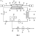
- FIG. 1 illustrated is an embodiment of an environmental control system 10 for, for example, a space vehicle.
- the system 10 utilizes a water coolant loop 12, through which a flow of water 14 is circulated by a pump 16.
- a temperature of the flow of water 14 is maintained by passing the flow of water 14 through a liquid-liquid heat exchanger 18.
- the flow of water 14 exchanges thermal energy with a flow of coolant 20 of a coolant loop 22, thus cooling the flow of water 14.
- the flow of coolant 20 enters the liquid-liquid heat exchanger 18 at a coolant inlet 24 and exits the liquid-liquid heat exchanger 18 at a coolant outlet 26.
- the pump 16 is located along the water coolant loop 12 downstream of the liquid-liquid heat exchanger 18, but in other embodiments the pump 16 may be located upstream of the liquid-liquid heat exchanger 18.
- a condensing heat exchanger (CHX) and water separator 28 is located along the water coolant loop 12, in some embodiments upstream of the liquid-liquid heat exchanger 18.
- the flow of water 14 enters the CHX and water separator 28 at a water inlet 30 and exits the CHX and water separator 28 at a water outlet 32.
- a flow of return air 34 from, for example, a vehicle cabin 36 enters the CHX and water separator 28 at an air inlet 38.
- the return air 34 is conditioned at the CHX and water separator 28 and output as a flow of conditioned air 40 as an air outlet 42.
- the flow of conditioned air 40 is directed to the vehicle cabin 36.
- the CHX and water separator 28 includes a first cover plate 44 and a second cover plate 46, opposite the first cover plate 44, that are spaced apart.
- a plurality of microporous graphite plates 48 are stacked between the first cover plate 44 and the second cover plate 46.
- the cover plates 44, 46 and the microporous graphite plates 48 each have a plurality of grooves 50 defined therein, such that when stacked, the grooves 50 define a plurality of passages.
- Such passages are either air passages 52 or water passages 54, depending on the medium flowing therethrough.
- the CHX and water separator 28 has a plurality of alternating layers of air passages 52 and layers of water passages 54, with adjacent layers separated by a microporous graphite plate 48.
- Each water passage 54 is fluidly connected to the water inlet 30 and the water outlet 32 such that the flow of water 14 is directed through the plurality of water passages 54.
- each air passage 52 is fluidly connected to the air inlet 38 and the air outlet 42 such that the return air 34 is directed into the plurality of air passages 52 from the air inlet 38, and the conditioned air 40 is directed from the plurality of air passages 52 to the air outlet 42.
- the CHX and water separator 28 is a counterflow configuration. Referring to FIG.
- the plurality of air passages 52 has a single pass configuration, while as shown in FIG. 3b the plurality of water passages 54 has a multi-pass configuration, for example three passes as shown. It will be appreciated, however, that other numbers of passes may be utilized.
- the multi-pass configuration of the water passages 54 increases a velocity of the water therein, thereby increasing the heat transfer coefficient and reducing a chance of surface fouling.
- a differential pressure ( ⁇ P) is maintained between the airflow and the water coolant flow, such that the airflow pressure at air outlet 42 is greater than the water coolant flow pressure at water outlet 32, as indicated in FIG. 2 .
- the differential pressure is achieved by maintaining the water coolant flow at sub-ambient, which will be described in more detail below.
- the flow of relatively humid return air 34 is directed into the plurality of air passages 52 via the air inlet 38, and the flow of water 14 is introduced to the plurality of water passages 54 via the water inlet 30.
- the differential pressure is maintained below a bubble point of the microporous graphite plate 48 to prevent the ingress of airflow through the microporous graphite plate 48 and into the plurality of water passages 54.
- the flow of water 14 exits the CHX and water separator 28 at the water outlet 32, and the air flow, now as conditioned air 40 exits the CHX and water separator 28 at the air outlet 42.
- the air passages 52 include offset passages 80. This will prevent any entrainment of water droplets that have yet to wick through the microporous layer into the air stream - the droplets will impinge into the sidewall of the flow passage and be wicked into the microporous material. This is primarily in the event the surface on the air side of the heat exchanger has been fouled locally to reduce its hydrophilic nature and make it somewhat hydrophobic - so the water has a harder time wicking through the microporous layer.
- the system 10 further includes a vented bellows accumulator 62 and a flow metering orifice 64 located along the water coolant loop 12 to maintain the selected differential pressure.
- the accumulator 62 and the flow metering orifice 64 are located between the pump 16 and the CHX and water separator 28.
- Water or condensate is periodically removed from the water coolant loop 12 for processing, for example, when needed for use by the vehicle or when a water level in the accumulator 62 reaches a selected threshold.
- a water output line 66 is connected to the water coolant loop 12 for removal of the water.
- the water output line 66 includes a solenoid valve 68, an output pump 70 and a relief valve 72. When the solenoid valve 68 is opened and the output pump 70 is activated, water is urged along the water output line 66 and through the relief valve 72. When a desired volume of water has been removed from the water coolant loop 12, the output pump 70 is deactivated and the solenoid valve 68 is closed.
- the CHX and water separator 28 combines the CHX and water separator functions into a single, passive component thereby improving overall reliability of an environmental control system into which it is included.
Landscapes
- Engineering & Computer Science (AREA)
- Mechanical Engineering (AREA)
- General Engineering & Computer Science (AREA)
- Physics & Mathematics (AREA)
- Thermal Sciences (AREA)
- Chemical & Material Sciences (AREA)
- Dispersion Chemistry (AREA)
- Life Sciences & Earth Sciences (AREA)
- Health & Medical Sciences (AREA)
- Biodiversity & Conservation Biology (AREA)
- Environmental & Geological Engineering (AREA)
- Environmental Sciences (AREA)
- General Health & Medical Sciences (AREA)
- Toxicology (AREA)
- Remote Sensing (AREA)
- Aviation & Aerospace Engineering (AREA)
- Combustion & Propulsion (AREA)
- Heat-Exchange Devices With Radiators And Conduit Assemblies (AREA)
- Drying Of Gases (AREA)
Abstract
Description
- Exemplary embodiments pertain to the art of environmental control systems for, for example, space vehicles.
- Such environmental control systems typically include a temperature and humidity control system to provide a comfortable environment inside of the space vehicle. The typical system architecture includes a fan that directs space vehicle cabin air into a condensing heat exchanger to remove moisture from the cabin air, and a separate rotary water separator to remove condensate from the cabin air stream. The rotary water separator relies on centrifugal force to separate water from the airstream and requires significant power for operation. Further the typical condensing heat exchanger is expensive to produce and typically requires long lead times due to limited production.
- In one embodiment, an integrated condensing heat exchanger and water separator includes a microporous graphite plate, one or more water passages defined at a first side of the microporous graphite plate, and one or more air passages defined at a second side of the microporous graphite plate opposite the first side. An air inlet operably is connected to the one or more air passages to direct a flow of air through the one or more air passages at a first pressure, and a water inlet is operably connected to the one or more water passages to direct a flow of water through the one or more water passages at a second pressure lower than the first pressure. The microporous graphite plate is configured such that moisture condenses from the flow of air onto the second side and is wicked through the microporous graphite plate to the one or more water passages to join the flow of water.
- Additionally or alternatively, in this or other embodiments a difference between the first pressure and the second pressure is maintained below a bubble point of the microporous graphite plate to prevent the ingress of the flow of air through the microporous graphite plate and into the one or more water passages.
- Additionally or alternatively, in this or other embodiments the second pressure is sub-ambient.
- Additionally or alternatively, in this or other embodiments the microporous graphite plate includes a plurality of first grooves at the first side to at least partially define the one or more water passages, and a plurality of second grooves at the second side to at least partially define the one or more air passages.
- In another embodiment, a condensing heat exchanger and water separator includes a plurality of microporous graphite plates arranged in a stack, each microporous graphite plate having one or more water passages defined at a first side of the microporous graphite plate, and one or more air passages defined at a second side of the microporous graphite plate opposite the first side. An air inlet is operably connected to the one or more air passages to direct a flow of air through the one or more air passages at a first pressure, and a water inlet is operably connected to the one or more water passages to direct a flow of water through the one or more water passages at a second pressure lower than the first pressure. The plurality of microporous graphite plates are configured such that moisture condenses from the flow of air onto the second side and is wicked through the microporous graphite plates to the one or more water passages to join the flow of water.
- Additionally or alternatively, in this or other embodiments each microporous graphite plate of the plurality of microporous graphite plates includes a plurality of first grooves at the first side to at least partially define the one or more water passages, and a plurality of second grooves at the second side to at least partially define the one or more air passages.
- Additionally or alternatively, in this or other embodiments a cover plate is located at one or more of a first stack side and a second stack side of the stack of microporous graphite plates.
- Additionally or alternatively, in this or other embodiments an air outlet is operably connected to the one or more air passages to output a flow of conditioned air from the condensing heat exchanger and water separator.
- Additionally or alternatively, in this or other embodiments a difference between the first pressure and the second pressure is maintained below a bubble point of the microporous graphite plate to prevent the ingress of the flow of air through the microporous graphite plate and into the one or more water passages.
- Additionally or alternatively, in this or other embodiments the second pressure is sub-ambient.
- In yet another embodiment, an environmental control system includes a liquid-liquid heat exchanger, a pump, and a condensing heat exchanger and water separator. The liquid-liquid heat exchanger, the pump and the condensing heat exchanger and water separator are arranged in a serial arrangement to define a water coolant loop with a flow of water circulating therethrough. The condensing heat exchanger and water separator includes a microporous graphite plate, one or more water passages defined at a first side of the microporous graphite plate, and one or more air passages defined at a second side of the microporous graphite plate opposite the first side. An air inlet is operably connected to the one or more air passages to direct a flow of air through the one or more air passages at a first pressure, and a water inlet is operably connected to the one or more water passages to direct a flow of water through the one or more water passages at a second pressure lower than the first pressure. The microporous graphite plate is configured such that moisture condenses from the flow of air onto the second side and is wicked through the microporous graphite plate to the one or more water passages to join the flow of water.
- Additionally or alternatively, in this or other embodiments a difference between the first pressure and the second pressure is maintained below a bubble point of the microporous graphite plate to prevent the ingress of the flow of air through the microporous graphite plate and into the one or more water passages.
- Additionally or alternatively, in this or other embodiments the second pressure is sub-ambient.
- Additionally or alternatively, in this or other embodiments the microporous graphite plate includes a plurality of first grooves at the first side to at least partially define the one or more water passages, and a plurality of second grooves at the second side to at least partially define the one or more air passages.
- Additionally or alternatively, in this or other embodiments a vented bellows accumulator and flow metering orifice are arranged along the water coolant loop to maintain the selected second pressure of the flow of water.
- Additionally or alternatively, in this or other embodiments the bellows accumulator is positioned along the water coolant loop between the pump and the condensing heat exchanger and water separator.
- Additionally or alternatively, in this or other embodiments a temperature of the flow of water is maintained by thermal energy exchange with a flow of coolant at the liquid-liquid heat exchanger.
- Additionally or alternatively, in this or other embodiments a water output line is fluidly connected to the water coolant loop. The water output line is configured to selectably remove water from the water coolant loop.
- Additionally or alternatively, in this or other embodiments an output pump is located along the water output line.
- The following descriptions should not be considered limiting in any way. With reference to the accompanying drawings, like elements are numbered alike:
-
FIG. 1 is a schematic illustration of an embodiment of an environmental control system; -
FIG. 2 is a schematic illustration of an embodiment of an integrated condensing heat exchanger and water separator; -
FIG. 3a is a perspective view of an embodiment of a plurality of air passages; and -
FIG. 3b is a perspective view of an embodiment of a plurality of water passages. - A detailed description of one or more embodiments of the disclosed apparatus and method are presented herein by way of exemplification and not limitation with reference to the Figures.
- Referring now to
FIG. 1 , illustrated is an embodiment of anenvironmental control system 10 for, for example, a space vehicle. Thesystem 10 utilizes awater coolant loop 12, through which a flow ofwater 14 is circulated by apump 16. A temperature of the flow ofwater 14 is maintained by passing the flow ofwater 14 through a liquid-liquid heat exchanger 18. At the liquid-liquid heat exchanger 18, the flow ofwater 14 exchanges thermal energy with a flow ofcoolant 20 of acoolant loop 22, thus cooling the flow ofwater 14. In some embodiments, the flow ofcoolant 20 enters the liquid-liquid heat exchanger 18 at acoolant inlet 24 and exits the liquid-liquid heat exchanger 18 at acoolant outlet 26. In the embodiment illustrated, thepump 16 is located along thewater coolant loop 12 downstream of the liquid-liquid heat exchanger 18, but in other embodiments thepump 16 may be located upstream of the liquid-liquid heat exchanger 18. - A condensing heat exchanger (CHX) and
water separator 28 is located along thewater coolant loop 12, in some embodiments upstream of the liquid-liquid heat exchanger 18. The flow ofwater 14 enters the CHX andwater separator 28 at a water inlet 30 and exits the CHX andwater separator 28 at awater outlet 32. Similarly, a flow ofreturn air 34 from, for example, avehicle cabin 36 enters the CHX andwater separator 28 at anair inlet 38. Thereturn air 34 is conditioned at the CHX andwater separator 28 and output as a flow of conditionedair 40 as anair outlet 42. In some embodiments, the flow of conditionedair 40 is directed to thevehicle cabin 36. - Referring now to the cross-sectional view of
FIG. 2 , the CHX andwater separator 28 is illustrated in more detail. The CHX andwater separator 28 includes afirst cover plate 44 and asecond cover plate 46, opposite thefirst cover plate 44, that are spaced apart. A plurality ofmicroporous graphite plates 48 are stacked between thefirst cover plate 44 and thesecond cover plate 46. Thecover plates microporous graphite plates 48 each have a plurality ofgrooves 50 defined therein, such that when stacked, thegrooves 50 define a plurality of passages. Such passages are eitherair passages 52 orwater passages 54, depending on the medium flowing therethrough. - Thus, the CHX and
water separator 28 has a plurality of alternating layers ofair passages 52 and layers ofwater passages 54, with adjacent layers separated by amicroporous graphite plate 48. Eachwater passage 54 is fluidly connected to the water inlet 30 and thewater outlet 32 such that the flow ofwater 14 is directed through the plurality ofwater passages 54. Similarly, eachair passage 52 is fluidly connected to theair inlet 38 and theair outlet 42 such that thereturn air 34 is directed into the plurality ofair passages 52 from theair inlet 38, and the conditionedair 40 is directed from the plurality ofair passages 52 to theair outlet 42. In some embodiments, the CHX andwater separator 28 is a counterflow configuration. Referring toFIG. 3a , in some embodiments the plurality ofair passages 52 has a single pass configuration, while as shown inFIG. 3b the plurality ofwater passages 54 has a multi-pass configuration, for example three passes as shown. It will be appreciated, however, that other numbers of passes may be utilized. The multi-pass configuration of thewater passages 54 increases a velocity of the water therein, thereby increasing the heat transfer coefficient and reducing a chance of surface fouling. - A differential pressure (ΔP) is maintained between the airflow and the water coolant flow, such that the airflow pressure at
air outlet 42 is greater than the water coolant flow pressure atwater outlet 32, as indicated inFIG. 2 . In some embodiments, the differential pressure is achieved by maintaining the water coolant flow at sub-ambient, which will be described in more detail below. In operation, the flow of relativelyhumid return air 34 is directed into the plurality ofair passages 52 via theair inlet 38, and the flow ofwater 14 is introduced to the plurality ofwater passages 54 via thewater inlet 30. - As the flow of
water 14 flows on afirst side 56 of themicroporous graphite plate 48, and thereturn airflow 34 flows along asecond side 58 of themicroporous graphite plate 48, moisture from thereturn airflow 34 condenses onto thesecond side 58 of themicroporous graphite plate 48. As the moisture condenses, a hydrophilic treatment of themicroporous graphite plate 48 wicks the condensed moisture into a plurality of micropores of themicroporous graphite plate 48. Thecondensed moisture 60 is urged into the plurality ofwater passages 54 at thefirst side 56 of themicroporous graphite plate 48. The differential pressure is maintained below a bubble point of themicroporous graphite plate 48 to prevent the ingress of airflow through themicroporous graphite plate 48 and into the plurality ofwater passages 54. The flow ofwater 14 exits the CHX andwater separator 28 at thewater outlet 32, and the air flow, now asconditioned air 40 exits the CHX andwater separator 28 at theair outlet 42. - Referring again to
FIG. 3a , in some embodiments, theair passages 52 include offsetpassages 80. This will prevent any entrainment of water droplets that have yet to wick through the microporous layer into the air stream - the droplets will impinge into the sidewall of the flow passage and be wicked into the microporous material. This is primarily in the event the surface on the air side of the heat exchanger has been fouled locally to reduce its hydrophilic nature and make it somewhat hydrophobic - so the water has a harder time wicking through the microporous layer. - Returning now to
FIG. 1 , thesystem 10 further includes a vented bellowsaccumulator 62 and aflow metering orifice 64 located along thewater coolant loop 12 to maintain the selected differential pressure. In some embodiments, theaccumulator 62 and theflow metering orifice 64 are located between thepump 16 and the CHX andwater separator 28. - Water or condensate is periodically removed from the
water coolant loop 12 for processing, for example, when needed for use by the vehicle or when a water level in theaccumulator 62 reaches a selected threshold. Awater output line 66 is connected to thewater coolant loop 12 for removal of the water. Thewater output line 66 includes asolenoid valve 68, anoutput pump 70 and arelief valve 72. When thesolenoid valve 68 is opened and theoutput pump 70 is activated, water is urged along thewater output line 66 and through therelief valve 72. When a desired volume of water has been removed from thewater coolant loop 12, theoutput pump 70 is deactivated and thesolenoid valve 68 is closed. - As described herein, the CHX and
water separator 28 combines the CHX and water separator functions into a single, passive component thereby improving overall reliability of an environmental control system into which it is included. - The term "about" is intended to include the degree of error associated with measurement of the particular quantity based upon the equipment available at the time of filing the application.
- The terminology used herein is for the purpose of describing particular embodiments only and is not intended to be limiting of the present disclosure. As used herein, the singular forms "a", "an" and "the" are intended to include the plural forms as well, unless the context clearly indicates otherwise. It will be further understood that the terms "comprises" and/or "comprising," when used in this specification, specify the presence of stated features, integers, steps, operations, elements, and/or components, but do not preclude the presence or addition of one or more other features, integers, steps, operations, element components, and/or groups thereof.
- While the present disclosure has been described with reference to an exemplary embodiment or embodiments, it will be understood by those skilled in the art that various changes may be made and equivalents may be substituted for elements thereof without departing from the scope of the present disclosure. In addition, many modifications may be made to adapt a particular situation or material to the teachings of the present disclosure without departing from the essential scope thereof. Therefore, it is intended that the present disclosure not be limited to the particular embodiment disclosed as the best mode contemplated for carrying out this present disclosure, but that the present disclosure will include all embodiments falling within the scope of the claims.
Claims (15)
- An integrated condensing heat exchanger and water separator comprising:a microporous graphite plate (48);one or more water passages (54) defined at a first side of the microporous graphite plate;one or more air passages (52) defined at a second side of the microporous graphite plate opposite the first side;an air inlet (38) operably connected to the one or more air passages to direct a flow of air through the one or more air passages at a first pressure; anda water inlet (30) operably connected to the one or more water passages to direct a flow of water through the one or more water passages at a second pressure lower than the first pressure;wherein the microporous graphite plate is configured such that moisture condenses from the flow of air onto the second side and is wicked through the microporous graphite plate to the one or more water passages to join the flow of water.
- The condensing heat exchanger and water separator of claim 1, wherein a difference between the first pressure and the second pressure is maintained below a bubble point of the microporous graphite plate to prevent the ingress of the flow of air through the microporous graphite plate and into the one or more water passages.
- The condensing heat exchanger and water separator of any preceding claim, wherein the second pressure is sub-ambient.
- The condensing heat exchanger and water separator of any preceding claim, wherein the microporous graphite plate includes:a plurality of first grooves at the first side to at least partially define the one or more water passages; anda plurality of second grooves at the second side to at least partially define the one or more air passages.
- A condensing heat exchanger and water separator, comprising:
a plurality of microporous graphite plates (48) arranged in a stack, each microporous graphite plate having:one or more water passages (54) defined at a first side of the microporous graphite plate; andone or more air passages (52) defined at a second side of the microporous graphite plate opposite the first side;an air inlet (38) operably connected to the one or more air passages to direct a flow of air through the one or more air passages at a first pressure; anda water inlet (30) operably connected to the one or more water passages to direct a flow of water through the one or more water passages at a second pressure lower than the first pressure;wherein the plurality of microporous graphite plates are configured such that moisture condenses from the flow of air onto the second side and is wicked through the microporous graphite plates to the one or more water passages to join the flow of water. - The condensing heat exchanger and water separator of claim 5, wherein each microporous graphite plate of the plurality of microporous graphite plates includes:a plurality of first grooves at the first side to at least partially define the one or more water passages; anda plurality of second grooves at the second side to at least partially define the one or more air passages.
- The condensing heat exchanger and water separator of claim 5 or 6, further comprising a cover plate disposed at one or more of a first stack side and a second stack side of the stack of microporous graphite plates.
- The condensing heat exchanger and water separator of any of claims 5-7, further comprising an air outlet operably connected to the one or more air passages to output a flow of conditioned air from the condensing heat exchanger and water separator.
- The condensing heat exchanger and water separator of any of claims 5-8, wherein a difference between the first pressure and the second pressure is maintained below a bubble point of the microporous graphite plate to prevent the ingress of the flow of air through the microporous graphite plate and into the one or more water passages.
- The condensing heat exchanger and water separator of any of claims 5-9, wherein the second pressure is sub-ambient.
- An environmental control system, comprising:a liquid-liquid heat exchanger;a pump; anda condensing heat exchanger and water separator (28);wherein the liquid-liquid heat exchanger, the pump and the condensing heat exchanger and water separator are arranged in a serial arrangement to define a water coolant loop with a flow of water circulating therethrough; andwherein the condensing heat exchanger and water separator includes:a microporous graphite plate (48);one or more water passages (54) defined at a first side of the microporous graphite plate;one or more air passages (52) defined at a second side of the microporous graphite plate opposite the first side;an air inlet (38) operably connected to the one or more air passages to direct a flow of air through the one or more air passages at a first pressure; anda water inlet (30) operably connected to the one or more water passages to direct a flow of water through the one or more water passages at a second pressure lower than the first pressure;wherein the microporous graphite plate is configured such that moisture condenses from the flow of air onto the second side and is wicked through the microporous graphite plate to the one or more water passages to join the flow of water.
- The environmental control system of claim 11, wherein a difference between the first pressure and the second pressure is maintained below a bubble point of the microporous graphite plate to prevent the ingress of the flow of air through the microporous graphite plate and into the one or more water passages.
- The environmental control system of claim 11 or 12, wherein the second pressure is sub-ambient; and/or
wherein the microporous graphite plate includes:a plurality of first grooves at the first side to at least partially define the one or more water passages; anda plurality of second grooves at the second side to at least partially define the one or more air passages. - The environmental control system of any of claims 11-13, further comprising a vented bellows accumulator and flow metering orifice arranged along the water coolant loop to maintain the selected second pressure of the flow of water, and preferably wherein the bellows accumulator is disposed along the water coolant loop between the pump and the condensing heat exchanger and water separator; and/or
wherein a temperature of the flow of water is maintained by thermal energy exchange with a flow of coolant at the liquid-liquid heat exchanger. - The environmental control system of any of claims 11-14, further comprising a water output line fluidly connected to the water coolant loop, the water output line configured to selectably remove water from the water coolant loop, and preferably further comprising an output pump disposed along the water output line.
Applications Claiming Priority (1)
| Application Number | Priority Date | Filing Date | Title |
|---|---|---|---|
| US17/097,750 US20220153456A1 (en) | 2020-11-13 | 2020-11-13 | Integrated condensing heat exchanger and water separator |
Publications (1)
| Publication Number | Publication Date |
|---|---|
| EP4001817A1 true EP4001817A1 (en) | 2022-05-25 |
Family
ID=78087222
Family Applications (1)
| Application Number | Title | Priority Date | Filing Date |
|---|---|---|---|
| EP21202000.2A Pending EP4001817A1 (en) | 2020-11-13 | 2021-10-11 | Integrated condensing heat exchanger and water separator |
Country Status (3)
| Country | Link |
|---|---|
| US (1) | US20220153456A1 (en) |
| EP (1) | EP4001817A1 (en) |
| JP (1) | JP7785506B2 (en) |
Citations (2)
| Publication number | Priority date | Publication date | Assignee | Title |
|---|---|---|---|---|
| US6232006B1 (en) * | 1998-12-18 | 2001-05-15 | International Fuel Cells Llc | Dual coolant loop fuel cell power plant |
| US8470483B2 (en) * | 2006-12-27 | 2013-06-25 | Utc Power Corporation | Wettable gas diffusion layer for a wet seal in a fuel cell |
Family Cites Families (10)
| Publication number | Priority date | Publication date | Assignee | Title |
|---|---|---|---|---|
| US5368786A (en) * | 1992-09-30 | 1994-11-29 | Wisconsin Alumni Research Foundation | Apparatus and methods for humidity control |
| FR2705445B1 (en) * | 1993-05-18 | 1995-07-07 | Vicarb Sa | Plate heat exchanger. |
| US7504170B2 (en) * | 2004-12-29 | 2009-03-17 | Utc Power Corporation | Fuel cells evaporatively cooled with water carried in passageways |
| WO2011069015A2 (en) * | 2009-12-02 | 2011-06-09 | The Regents Of The University Of Colorado, A Body Corporate | Microchannel expanded heat exchanger |
| KR101939416B1 (en) * | 2010-11-12 | 2019-01-16 | 더 텍사스 에이 & 엠 유니버시티 시스템 | Systems and methods for air dehumidification and sensible cooling using a multiple stage pump |
| JP6040570B2 (en) * | 2012-05-23 | 2016-12-07 | 株式会社平安製作所 | Heat exchanger |
| DE102012024549B4 (en) * | 2012-12-17 | 2018-02-01 | Al-Ko Therm Gmbh | Plate unit and gas-gas material exchanger |
| JP2016176674A (en) * | 2015-03-23 | 2016-10-06 | 株式会社東芝 | Water recovery system, humidification system and air conditioning system |
| US20190086156A1 (en) * | 2016-02-11 | 2019-03-21 | Rosenberger Hochfrequenztechnik Gmbh & Co., Kg | Cross-flow plate heat and/or moisture exchanger |
| US10287037B2 (en) * | 2016-03-31 | 2019-05-14 | Oceaneering International, Inc. | Membrane microgravity air conditoner |
-
2020
- 2020-11-13 US US17/097,750 patent/US20220153456A1/en not_active Abandoned
-
2021
- 2021-10-11 EP EP21202000.2A patent/EP4001817A1/en active Pending
- 2021-11-10 JP JP2021182943A patent/JP7785506B2/en active Active
Patent Citations (2)
| Publication number | Priority date | Publication date | Assignee | Title |
|---|---|---|---|---|
| US6232006B1 (en) * | 1998-12-18 | 2001-05-15 | International Fuel Cells Llc | Dual coolant loop fuel cell power plant |
| US8470483B2 (en) * | 2006-12-27 | 2013-06-25 | Utc Power Corporation | Wettable gas diffusion layer for a wet seal in a fuel cell |
Also Published As
| Publication number | Publication date |
|---|---|
| JP2022078964A (en) | 2022-05-25 |
| JP7785506B2 (en) | 2025-12-15 |
| US20220153456A1 (en) | 2022-05-19 |
Similar Documents
| Publication | Publication Date | Title |
|---|---|---|
| JP5248629B2 (en) | Indirect evaporative cooler using liquid desiccant contained in membrane for dehumidification | |
| US6460353B2 (en) | Method and apparatus for improved aircraft environmental control system utilizing parallel heat exchanger arrays | |
| US5921088A (en) | Air conditioning apparatus | |
| CN106662405B (en) | Combined convector | |
| EP0542909B1 (en) | Environmental control system condensing cycle | |
| KR102396679B1 (en) | An air conditioning method using a staged process using a liquid desiccant | |
| EP2863162B1 (en) | Air-to-air heat exchanger bypass for wet cooling tower apparatus and method | |
| US10502438B2 (en) | Latent and sensible cooling membrane heat pump | |
| EP3690335B1 (en) | Improved high pressure water extraction device with shave off edge that feeds a low pressure chamber to improve water collection and drainage | |
| US20050210907A1 (en) | Indirect evaporative cooling of a gas using common product and working gas in a partial counterflow configuration | |
| WO2007105450A1 (en) | Heat removing method and heat removing apparatus | |
| BR112014012144B1 (en) | heat exchange matrix | |
| US20040258968A1 (en) | Cathode inlet gas humidification system and method for a fuel cell system | |
| SE524938C2 (en) | Heat exchanger and method for drying a moist medium | |
| SE460618B (en) | SET AND CONDITION TO CONDITION A GAS IN A ROTATING REGENERATIVE MOISTURE EXCHANGE DEVICE | |
| US10024557B2 (en) | Water extractor device using scuppers | |
| US20220153456A1 (en) | Integrated condensing heat exchanger and water separator | |
| JP2017507847A (en) | HVAC system for vehicle and housing of dual HVAC system | |
| EP3077756B1 (en) | Asymmetric evaporator | |
| CN113748306A (en) | Total heat exchange element | |
| US20180209670A1 (en) | Moisture separation system | |
| SE540735C2 (en) | Method for counteracting the build-up of frost on a heat recycler arranged at an air treatment unit | |
| WO2020138075A1 (en) | Outer panel cooling system | |
| EP0515575A1 (en) | Fluid conditioning apparatus and system | |
| US20170219228A1 (en) | Dynamic cycle air conditioner with incremental dehumidification incorporating a wet passage and a dry passage |
Legal Events
| Date | Code | Title | Description |
|---|---|---|---|
| PUAI | Public reference made under article 153(3) epc to a published international application that has entered the european phase |
Free format text: ORIGINAL CODE: 0009012 |
|
| STAA | Information on the status of an ep patent application or granted ep patent |
Free format text: STATUS: THE APPLICATION HAS BEEN PUBLISHED |
|
| AK | Designated contracting states |
Kind code of ref document: A1 Designated state(s): AL AT BE BG CH CY CZ DE DK EE ES FI FR GB GR HR HU IE IS IT LI LT LU LV MC MK MT NL NO PL PT RO RS SE SI SK SM TR |
|
| STAA | Information on the status of an ep patent application or granted ep patent |
Free format text: STATUS: REQUEST FOR EXAMINATION WAS MADE |
|
| 17P | Request for examination filed |
Effective date: 20221117 |
|
| RBV | Designated contracting states (corrected) |
Designated state(s): AL AT BE BG CH CY CZ DE DK EE ES FI FR GB GR HR HU IE IS IT LI LT LU LV MC MK MT NL NO PL PT RO RS SE SI SK SM TR |
|
| STAA | Information on the status of an ep patent application or granted ep patent |
Free format text: STATUS: EXAMINATION IS IN PROGRESS |
|
| 17Q | First examination report despatched |
Effective date: 20240430 |