BR112014012144B1 - heat exchange matrix - Google Patents
heat exchange matrix Download PDFInfo
- Publication number
- BR112014012144B1 BR112014012144B1 BR112014012144-3A BR112014012144A BR112014012144B1 BR 112014012144 B1 BR112014012144 B1 BR 112014012144B1 BR 112014012144 A BR112014012144 A BR 112014012144A BR 112014012144 B1 BR112014012144 B1 BR 112014012144B1
- Authority
- BR
- Brazil
- Prior art keywords
- strip
- sheet
- strips
- flow
- fact
- Prior art date
Links
Images


Classifications
-
- F—MECHANICAL ENGINEERING; LIGHTING; HEATING; WEAPONS; BLASTING
- F28—HEAT EXCHANGE IN GENERAL
- F28C—HEAT-EXCHANGE APPARATUS, NOT PROVIDED FOR IN ANOTHER SUBCLASS, IN WHICH THE HEAT-EXCHANGE MEDIA COME INTO DIRECT CONTACT WITHOUT CHEMICAL INTERACTION
- F28C3/00—Other direct-contact heat-exchange apparatus
- F28C3/06—Other direct-contact heat-exchange apparatus the heat-exchange media being a liquid and a gas or vapour
- F28C3/08—Other direct-contact heat-exchange apparatus the heat-exchange media being a liquid and a gas or vapour with change of state, e.g. absorption, evaporation, condensation
-
- B—PERFORMING OPERATIONS; TRANSPORTING
- B01—PHYSICAL OR CHEMICAL PROCESSES OR APPARATUS IN GENERAL
- B01J—CHEMICAL OR PHYSICAL PROCESSES, e.g. CATALYSIS OR COLLOID CHEMISTRY; THEIR RELEVANT APPARATUS
- B01J19/00—Chemical, physical or physico-chemical processes in general; Their relevant apparatus
- B01J19/32—Packing elements in the form of grids or built-up elements for forming a unit or module inside the apparatus for mass or heat transfer
-
- B—PERFORMING OPERATIONS; TRANSPORTING
- B21—MECHANICAL METAL-WORKING WITHOUT ESSENTIALLY REMOVING MATERIAL; PUNCHING METAL
- B21D—WORKING OR PROCESSING OF SHEET METAL OR METAL TUBES, RODS OR PROFILES WITHOUT ESSENTIALLY REMOVING MATERIAL; PUNCHING METAL
- B21D13/00—Corrugating sheet metal, rods or profiles; Bending sheet metal, rods or profiles into wave form
-
- B—PERFORMING OPERATIONS; TRANSPORTING
- B21—MECHANICAL METAL-WORKING WITHOUT ESSENTIALLY REMOVING MATERIAL; PUNCHING METAL
- B21D—WORKING OR PROCESSING OF SHEET METAL OR METAL TUBES, RODS OR PROFILES WITHOUT ESSENTIALLY REMOVING MATERIAL; PUNCHING METAL
- B21D53/00—Making other particular articles
- B21D53/02—Making other particular articles heat exchangers or parts thereof, e.g. radiators, condensers fins, headers
- B21D53/04—Making other particular articles heat exchangers or parts thereof, e.g. radiators, condensers fins, headers of sheet metal
-
- B—PERFORMING OPERATIONS; TRANSPORTING
- B23—MACHINE TOOLS; METAL-WORKING NOT OTHERWISE PROVIDED FOR
- B23P—METAL-WORKING NOT OTHERWISE PROVIDED FOR; COMBINED OPERATIONS; UNIVERSAL MACHINE TOOLS
- B23P15/00—Making specific metal objects by operations not covered by a single other subclass or a group in this subclass
- B23P15/26—Making specific metal objects by operations not covered by a single other subclass or a group in this subclass heat exchangers or the like
-
- F—MECHANICAL ENGINEERING; LIGHTING; HEATING; WEAPONS; BLASTING
- F24—HEATING; RANGES; VENTILATING
- F24F—AIR-CONDITIONING; AIR-HUMIDIFICATION; VENTILATION; USE OF AIR CURRENTS FOR SCREENING
- F24F3/00—Air-conditioning systems in which conditioned primary air is supplied from one or more central stations to distributing units in the rooms or spaces where it may receive secondary treatment; Apparatus specially designed for such systems
- F24F3/12—Air-conditioning systems in which conditioned primary air is supplied from one or more central stations to distributing units in the rooms or spaces where it may receive secondary treatment; Apparatus specially designed for such systems characterised by the treatment of the air otherwise than by heating and cooling
- F24F3/14—Air-conditioning systems in which conditioned primary air is supplied from one or more central stations to distributing units in the rooms or spaces where it may receive secondary treatment; Apparatus specially designed for such systems characterised by the treatment of the air otherwise than by heating and cooling by humidification; by dehumidification
-
- F—MECHANICAL ENGINEERING; LIGHTING; HEATING; WEAPONS; BLASTING
- F24—HEATING; RANGES; VENTILATING
- F24F—AIR-CONDITIONING; AIR-HUMIDIFICATION; VENTILATION; USE OF AIR CURRENTS FOR SCREENING
- F24F6/00—Air-humidification, e.g. cooling by humidification
- F24F6/02—Air-humidification, e.g. cooling by humidification by evaporation of water in the air
-
- F—MECHANICAL ENGINEERING; LIGHTING; HEATING; WEAPONS; BLASTING
- F28—HEAT EXCHANGE IN GENERAL
- F28D—HEAT-EXCHANGE APPARATUS, NOT PROVIDED FOR IN ANOTHER SUBCLASS, IN WHICH THE HEAT-EXCHANGE MEDIA DO NOT COME INTO DIRECT CONTACT
- F28D19/00—Regenerative heat-exchange apparatus in which the intermediate heat-transfer medium or body is moved successively into contact with each heat-exchange medium
- F28D19/04—Regenerative heat-exchange apparatus in which the intermediate heat-transfer medium or body is moved successively into contact with each heat-exchange medium using rigid bodies, e.g. mounted on a movable carrier
- F28D19/041—Regenerative heat-exchange apparatus in which the intermediate heat-transfer medium or body is moved successively into contact with each heat-exchange medium using rigid bodies, e.g. mounted on a movable carrier with axial flow through the intermediate heat-transfer medium
- F28D19/042—Rotors; Assemblies of heat absorbing masses
-
- B—PERFORMING OPERATIONS; TRANSPORTING
- B01—PHYSICAL OR CHEMICAL PROCESSES OR APPARATUS IN GENERAL
- B01J—CHEMICAL OR PHYSICAL PROCESSES, e.g. CATALYSIS OR COLLOID CHEMISTRY; THEIR RELEVANT APPARATUS
- B01J2219/00—Chemical, physical or physico-chemical processes in general; Their relevant apparatus
- B01J2219/32—Details relating to packing elements in the form of grids or built-up elements for forming a unit of module inside the apparatus for mass or heat transfer
- B01J2219/322—Basic shape of the elements
- B01J2219/32203—Sheets
- B01J2219/32206—Flat sheets
-
- B—PERFORMING OPERATIONS; TRANSPORTING
- B01—PHYSICAL OR CHEMICAL PROCESSES OR APPARATUS IN GENERAL
- B01J—CHEMICAL OR PHYSICAL PROCESSES, e.g. CATALYSIS OR COLLOID CHEMISTRY; THEIR RELEVANT APPARATUS
- B01J2219/00—Chemical, physical or physico-chemical processes in general; Their relevant apparatus
- B01J2219/32—Details relating to packing elements in the form of grids or built-up elements for forming a unit of module inside the apparatus for mass or heat transfer
- B01J2219/322—Basic shape of the elements
- B01J2219/32203—Sheets
- B01J2219/3221—Corrugated sheets
-
- B—PERFORMING OPERATIONS; TRANSPORTING
- B01—PHYSICAL OR CHEMICAL PROCESSES OR APPARATUS IN GENERAL
- B01J—CHEMICAL OR PHYSICAL PROCESSES, e.g. CATALYSIS OR COLLOID CHEMISTRY; THEIR RELEVANT APPARATUS
- B01J2219/00—Chemical, physical or physico-chemical processes in general; Their relevant apparatus
- B01J2219/32—Details relating to packing elements in the form of grids or built-up elements for forming a unit of module inside the apparatus for mass or heat transfer
- B01J2219/322—Basic shape of the elements
- B01J2219/32203—Sheets
- B01J2219/32248—Sheets comprising areas that are raised or sunken from the plane of the sheet
- B01J2219/32251—Dimples, bossages, protrusions
-
- B—PERFORMING OPERATIONS; TRANSPORTING
- B01—PHYSICAL OR CHEMICAL PROCESSES OR APPARATUS IN GENERAL
- B01J—CHEMICAL OR PHYSICAL PROCESSES, e.g. CATALYSIS OR COLLOID CHEMISTRY; THEIR RELEVANT APPARATUS
- B01J2219/00—Chemical, physical or physico-chemical processes in general; Their relevant apparatus
- B01J2219/32—Details relating to packing elements in the form of grids or built-up elements for forming a unit of module inside the apparatus for mass or heat transfer
- B01J2219/322—Basic shape of the elements
- B01J2219/32203—Sheets
- B01J2219/32255—Other details of the sheets
- B01J2219/32262—Dimensions or size aspects
-
- B—PERFORMING OPERATIONS; TRANSPORTING
- B01—PHYSICAL OR CHEMICAL PROCESSES OR APPARATUS IN GENERAL
- B01J—CHEMICAL OR PHYSICAL PROCESSES, e.g. CATALYSIS OR COLLOID CHEMISTRY; THEIR RELEVANT APPARATUS
- B01J2219/00—Chemical, physical or physico-chemical processes in general; Their relevant apparatus
- B01J2219/32—Details relating to packing elements in the form of grids or built-up elements for forming a unit of module inside the apparatus for mass or heat transfer
- B01J2219/322—Basic shape of the elements
- B01J2219/32203—Sheets
- B01J2219/32265—Sheets characterised by the orientation of blocks of sheets
- B01J2219/32268—Sheets characterised by the orientation of blocks of sheets relating to blocks in the same horizontal level
-
- F—MECHANICAL ENGINEERING; LIGHTING; HEATING; WEAPONS; BLASTING
- F24—HEATING; RANGES; VENTILATING
- F24F—AIR-CONDITIONING; AIR-HUMIDIFICATION; VENTILATION; USE OF AIR CURRENTS FOR SCREENING
- F24F2203/00—Devices or apparatus used for air treatment
- F24F2203/10—Rotary wheel
-
- Y—GENERAL TAGGING OF NEW TECHNOLOGICAL DEVELOPMENTS; GENERAL TAGGING OF CROSS-SECTIONAL TECHNOLOGIES SPANNING OVER SEVERAL SECTIONS OF THE IPC; TECHNICAL SUBJECTS COVERED BY FORMER USPC CROSS-REFERENCE ART COLLECTIONS [XRACs] AND DIGESTS
- Y02—TECHNOLOGIES OR APPLICATIONS FOR MITIGATION OR ADAPTATION AGAINST CLIMATE CHANGE
- Y02B—CLIMATE CHANGE MITIGATION TECHNOLOGIES RELATED TO BUILDINGS, e.g. HOUSING, HOUSE APPLIANCES OR RELATED END-USER APPLICATIONS
- Y02B30/00—Energy efficient heating, ventilation or air conditioning [HVAC]
- Y02B30/54—Free-cooling systems
-
- Y—GENERAL TAGGING OF NEW TECHNOLOGICAL DEVELOPMENTS; GENERAL TAGGING OF CROSS-SECTIONAL TECHNOLOGIES SPANNING OVER SEVERAL SECTIONS OF THE IPC; TECHNICAL SUBJECTS COVERED BY FORMER USPC CROSS-REFERENCE ART COLLECTIONS [XRACs] AND DIGESTS
- Y10—TECHNICAL SUBJECTS COVERED BY FORMER USPC
- Y10T—TECHNICAL SUBJECTS COVERED BY FORMER US CLASSIFICATION
- Y10T29/00—Metal working
- Y10T29/49—Method of mechanical manufacture
- Y10T29/4935—Heat exchanger or boiler making
- Y10T29/49359—Cooling apparatus making, e.g., air conditioner, refrigerator
Abstract
MATRIZ DE TROCA DE CALOR. A presente invenção refere-se a uma matriz de troca de calor que compreende uma pluralidade de folhas geralmente planas (32, 34) compreendendo um material de retenção de água, disposto em uma relação espaçada substancialmente paralela. Cada folha (32, 34) define um plano principal (P) que tem uma direção de fluxo (F) e uma direção transversal (T) e as folhas (23, 34) compreendem tiras (36a, 36b, 36c) que se estendem por um comprimento de tira na direção transversal (T) e são separadas de cada tira vizinha (36a, 36b, 36c) na direção de fluxo (F), e cada tira (36a, 36b, 36c) é deslocada do plano principal (P) por uma distância que é diferente daquela de sua vizinha. A matriz pode ser provida em um canal de fluxo para ar a ser umidificado e resfriado.HEAT EXCHANGE MATRIX. The present invention relates to a heat exchange matrix comprising a plurality of generally flat sheets (32, 34) comprising a water retention material, arranged in a substantially parallel spaced relationship. Each sheet (32, 34) defines a main plane (P) that has a flow direction (F) and a transverse direction (T) and the sheets (23, 34) comprise strips (36a, 36b, 36c) that extend by a strip length in the transverse direction (T) and are separated from each neighboring strip (36a, 36b, 36c) in the flow direction (F), and each strip (36a, 36b, 36c) is offset from the main plane (P ) for a distance that is different from that of its neighbor. The matrix can be provided in a flow channel for air to be humidified and cooled.
Description
[001] A presente invenção refere-se a uma matriz de troca de ca- lor do tipo que pode ser usada como um umidificador adiabático para a introdução de umidade em um fluxo de fluido. A invenção ainda se re- fere a métodos de fabricação desses dispositivos. Uma matriz deste tipo pode operar para prover um resfriamento adiabático para fins do- mésticos e também pode ser usada para umidificação em combinação com sistemas convencionais de condicionamento e aquecimento de ar. Também pode ser usada para a remoção de umidade a partir de uma corrente de ar em combinação com um dessecante adequado.[001] The present invention relates to a heat exchange matrix of the type that can be used as an adiabatic humidifier for introducing moisture into a fluid flow. The invention still refers to methods of manufacturing these devices. Such a matrix can operate to provide adiabatic cooling for domestic purposes and can also be used for humidification in combination with conventional air conditioning and heating systems. It can also be used to remove moisture from an air stream in combination with a suitable desiccant.
[002] Os dispositivos de troca de calor de uma forma ou outra estão presentes em virtualmente todo dispositivo e processo. A execu- ção de uma ação invariavelmente envolve a liberação de energia na forma de calor. Se não requerido, o calor frequentemente será liberado para o ambiente através de uma superfície de condução de calor apropriada provida, por exemplo, com aletas de resfriamento. Se a quantidade de calor for excessiva ou se puder ser empregada para finalidades úteis, um trocador de calor específico poderá ser provido para o transporte de calor para longe, por exemplo, para um outro sis- tema. A troca de calor também pode ocorrer entre meios diferentes: - meios gasosos, líquidos e sólidos podem ter interfaces em todas as combinações, de acordo com a performance requerida.[002] Heat exchange devices in one form or another are present in virtually every device and process. The execution of an action invariably involves the release of energy in the form of heat. If not required, heat will often be released into the environment through an appropriate heat conducting surface provided, for example, with cooling fins. If the amount of heat is excessive or if it can be used for useful purposes, a specific heat exchanger can be provided to transport heat away, for example, to another system. Heat exchange can also occur between different media: - gaseous, liquid and solid media can have interfaces in all combinations, according to the required performance.
[003] Os sistemas adiabáticos também são conhecidos, os quais atuam por evaporação de um líquido, usualmente água, em uma cor- rente de ar. Esses sistemas não são trocadores de calor no sentido estrito, uma vez que eles não fazem primariamente com que o calor entre ou saia do sistema. De fato, eles servem meramente para mu- dança da temperatura da corrente de ar enquanto se eleva sua ental- pia apenas pelo calor sensível da água adicionada. Conforme a água evapora para a corrente de ar, o calor latente de evaporação desta água é provido pelo resfriamento da corrente de ar. Para ar relativa- mente quente seco, este método de resfriamento pode ser muito efici- ente.[003] Adiabatic systems are also known, which act by evaporating a liquid, usually water, in an air current. These systems are not heat exchangers in the strict sense, since they do not primarily cause heat to enter or leave the system. In fact, they serve merely to change the temperature of the air stream while raising its entrapment only by the sensitive heat of the added water. As the water evaporates into the air stream, the latent heat of evaporation from this water is provided by cooling the air stream. For relatively dry hot air, this cooling method can be very effective.
[004] Os resfriadores adiabáticos convencionais são expostos na US 3792841 e US 5143658. Esses dispositivos geralmente compreen- dem uma matriz formada por pilhas de placas corrugadas postas no topo de cada outra, de modo que as corrugações em camadas adja- centes sejam inclinadas umas com respeito às outras. As placas po- dem ser formadas de vários materiais, mas materiais de fibra orgânica ou inorgânica reforçada com resina são o mais comum. As placas são suportadas por um alojamento ou quadro, o qual pode prover cone- xões de entrada e de saída para se guiar um fluxo de ar através da pilha. Um arranjo de irrigação é provido para a aplicação de água de forma contínua ou intermitente ou um outro líquido evaporável para as placas. Em uma operação, o ar a ser resfriado é passado através da pilha. Assumindo que o ar não esteja plenamente saturado, ele absor- verá vapor de água a partir das placas. Ao fazê-lo, a temperatura do ar é diminuída, em direção à assim denominada temperatura de bulbo úmido, a qual é o mínimo teórico. Para dadas condições de operação, a eficiência desses dispositivos pode ser determinada pela energia de entrada requerida para acionamento da corrente de ar através da pi- lha. Isto de fato, é a única energia externa significativa requerida e é largamente determinada pela resistência ao fluxo geral da pilha e pela velocidade da corrente de ar. Um grande problema com os dispositivos da técnica anterior é que, de modo a se otimizar a eficiência, eles ten- dem a se tornar relativamente volumosos.[004] Conventional adiabatic coolers are exposed in US 3792841 and US 5143658. These devices generally comprise a matrix formed by stacks of corrugated plates placed on top of each other, so that the corrugations in adjacent layers are angled. with respect to the others. Plates can be formed from various materials, but resin-reinforced organic or inorganic fiber materials are the most common. The plates are supported by a housing or frame, which can provide inlet and outlet connections to guide an air flow through the stack. An irrigation arrangement is provided to apply water continuously or intermittently or another evaporable liquid to the plates. In one operation, the air to be cooled is passed through the stack. Assuming that the air is not fully saturated, it will absorb water vapor from the plates. In doing so, the air temperature is lowered, towards the so-called wet bulb temperature, which is the theoretical minimum. For given operating conditions, the efficiency of these devices can be determined by the input energy required to activate the air flow through the battery. This, in fact, is the only significant external energy required and is largely determined by the resistance to the overall flow of the stack and the speed of the air flow. A major problem with prior art devices is that, in order to optimize efficiency, they tend to become relatively bulky.
[005] Além do resfriamento adiabático, dispositivos de construção similar também são usados para a umidificação de correntes de ar pa- ra outras finalidades. Em particular, em um aquecimento integrado, sistemas de ventilação e condicionamento de ar (HVAC) são frequen- temente desejáveis, para o aumento de grau de umidade absoluto do ar para fins de conforto. Em particular, durante os meses de inverno, os sistemas de aquecimento tendem a fazer com que o ar se torne re- lativamente seco. Isto pode levar a problemas respiratórios, eletricida- de estática e outros desconfortos. A adição de umidade de uma ma- neira eficiente sem aumento do volume de instalação de HVAC seria desejável.[005] In addition to adiabatic cooling, devices of similar construction are also used for humidifying drafts for other purposes. In particular, in integrated heating, ventilation and air conditioning (HVAC) systems are often desirable, for increasing the degree of absolute humidity in the air for comfort purposes. In particular, during the winter months, heating systems tend to cause the air to become relatively dry. This can lead to breathing problems, static electricity and other discomforts. Adding moisture in an efficient manner without increasing the volume of HVAC installation would be desirable.
[006] Uma distinção importante dos dispositivos acima em rela- ção a trocadores de calor convencionais é que eles podem interagir com apenas um fluxo de mídia. Isto evita coletores complexos de en- trada e de saída e há geralmente pouca necessidade de considerar a condutividade térmica da matriz. Os trocadores de calor de ar para ar convencionais operam em fluxo cruzado ou contrafluxo com uma transferência de calor ocorrendo entre os canais primários e canais secundários, os quais devem ser selados uns em relação aos outros, por exemplo, por paredes de condução de calor. Uma consideração de projeto importante é a maneira pela qual um coeficiente de transferên- cia de carbono orgânico adequado é obtido para as paredes de con- dução. Uma outra consideração é como múltiplos canais entrelaçados se conectam aos coletores de entrada e de saída.[006] An important distinction from the above devices in relation to conventional heat exchangers is that they can interact with only one media stream. This avoids complex inlet and outlet collectors and there is generally little need to consider the thermal conductivity of the matrix. Conventional air-to-air heat exchangers operate in cross-flow or counter-flow with a heat transfer occurring between the primary channels and secondary channels, which must be sealed in relation to each other, for example, by heat conducting walls. An important design consideration is the way in which a suitable organic carbon transfer coefficient is obtained for the conduction walls. Another consideration is how multiple interlaced channels connect to the input and output collectors.
[007] Uma outra classe de trocadores de calor é a roda de recu- peração de calor. Esses dispositivos usam meios de troca de calor sensível e latente na forma de uma matriz que provê passagens de ar através das quais uma corrente de ar pode ser dirigida usando-se um ventilador ou soprador. As matrizes suportam um material dessecante que pode absorver umidade e pode assumir uma variedade de formas, tal como uma malha de fibra ou em favo de mel. Um tipo de matriz em favo de mel é formado por uma pluralidade de camadas espaçadas substancialmente paralelas de um material de folha, particularmente camadas alternativas de um material de folha corrugado e um material de folha liso. No último caso, as corrugações são geralmente paralelas e proveem uma pluralidade de passagens se estendendo axialmente ao longo da profundidade da roda. Esses dispositivos são expostos na US 4769053 e na US 5542968. Materiais diferentes podem ser propos- tos para a construção de matriz incluindo alumínio e materiais fibrosos. Uma atenção considerável foi dada para o uso otimizado dos revesti- mentos de dessecante. Não obstante, uma desvantagem em particular dessas rodas é seu volume geral. Isto geralmente está relacionado ao volume de material requerido para uma troca efetiva de calor e à ne- cessidade de um fluxo efetivo através de uma área que não leve a uma queda de pressão significativa e a um consumo de potência alto associado pelo ventilador.[007] Another class of heat exchangers is the heat recovery wheel. These devices use sensitive and latent heat exchange means in the form of a matrix that provides air passages through which an air stream can be directed using a fan or blower. The dies support a desiccant material that can absorb moisture and can take a variety of shapes, such as a fiber mesh or honeycomb. One type of honeycomb matrix is formed by a plurality of substantially parallel spaced layers of a sheet material, particularly alternative layers of a corrugated sheet material and a smooth sheet material. In the latter case, the corrugations are generally parallel and provide a plurality of passages extending axially along the depth of the wheel. These devices are shown in US 4769053 and US 5542968. Different materials can be proposed for matrix construction including aluminum and fibrous materials. Considerable attention has been paid to the optimal use of desiccant coatings. However, a particular disadvantage of these wheels is their overall volume. This is usually related to the volume of material required for effective heat exchange and the need for effective flow through an area that does not lead to a significant pressure drop and high power consumption associated with the fan.
[008] Muitas outras formas de construção de troca de calor foram propostas no passado para várias finalidades diferentes. A US 4147210 expõe um trocador de calor de tela compreendendo telas e espaçadores alternados. As telas são feitas de um material condutivo, tal como cobre ou alumínio na forma de uma malha.[008] Many other forms of heat exchange construction have been proposed in the past for several different purposes. US 4147210 exposes a screen heat exchanger comprising alternating screens and spacers. The screens are made of a conductive material, such as copper or aluminum in the form of a mesh.
[009] Portanto, seria desejável melhorar os projetos existentes, pelo menos em termos de volume de matriz para uma dada perfor- mance, mas também em termos da eficiência de energia de fluxo atra- vés do dispositivo.[009] Therefore, it would be desirable to improve existing projects, at least in terms of matrix volume for a given performance, but also in terms of the energy efficiency of flow through the device.
[0010] De acordo com a invenção, é provida uma matriz de troca de calor que define um canal de fluxo e que compreende uma plurali- dade de folhas geralmente planas compreendendo um material de re- tenção de água, dispostas em uma relação espaçada substancialmen- te paralela, cada folha definindo um plano principal, que tem uma dire- ção de fluxo e uma direção transversal, em que as folhas compreen- dem tiras que se estendem por um comprimento de tira na direção transversal e são separadas de cada tira vizinha na direção de fluxo, e cada tira é deslocada do plano principal por uma distância que é dife- rente daquela de sua vizinha. Acredita-se que a matriz resultante ob- tenha uma capacidade de troca de calor consideravelmente mais alta por volume unitário e, mais ainda, acredita-se que tenha uma eficiên- cia maior em termos de resistência a fluxo às velocidades de ar geral- mente encontradas em aplicações de HVAC. No presente contexto, uma relação espaçada é entendida meramente como os planos princi- pais de cada folha são espaçados uns dos outros. As tiras de folhas adjacentes assim podem entrar em contato umas com as outras e as- sim podem ajudar na obtenção da função de espaçamento. Mais ain- da, embora uma referência seja dada a folhas planas, isto pode ser entendido para referência a sua disposição local e não é pretendida para ser limitante para o formato geral da matriz, o que pode ser adap- tado ao uso para qualquer formato apropriado. Em geral, contudo, as folhas serão planas pelo menos na direção de fluxo e planas ou curvas na direção transversal, conforme será descrito abaixo.[0010] According to the invention, a heat exchange matrix is provided which defines a flow channel and which comprises a plurality of generally flat sheets comprising a water retention material, arranged in a substantially spaced relation - parallel, each sheet defining a main plane, which has a flow direction and a transverse direction, in which the sheets comprise strips that extend along a strip length in the transverse direction and are separated from each neighbor strip in the flow direction, and each strip is moved from the main plane by a distance that is different from that of its neighbor. The resulting matrix is believed to have a considerably higher heat exchange capacity per unit volume and, moreover, it is believed to have a greater efficiency in terms of resistance to flow at air velocities generally found in HVAC applications. In the present context, a spaced relationship is understood merely as the main planes of each leaf are spaced from each other. Strips of adjacent sheets can thus come into contact with each other and thus help to achieve the spacing function. Furthermore, although a reference is given to flat sheets, this can be understood to refer to your local layout and is not intended to be limiting to the general format of the matrix, which can be adapted to use for any format appropriate. In general, however, the leaves will be flat at least in the direction of flow and flat or curved in the transverse direction, as will be described below.
[0011] Embora várias configurações e orientações das tiras pos- sam ser consideradas, não obstante, em geral, as tiras ficam geral- mente paralelas à direção de fluxo. Sem desejar ser limitado pela teo- ria, acredita-se que uma disposição de todas ou de maioria das tiras para ficar na direção do fluxo seja vantajosa na redução da queda de pressão através do trocador de calor.[0011] Although various configurations and orientations of the strips can be considered, however, in general, the strips are generally parallel to the direction of flow. Without wishing to be limited by theory, it is believed that an arrangement of all or most strips to be in the direction of flow is advantageous in reducing the pressure drop through the heat exchanger.
[0012] De acordo com a presente invenção, a matriz de troca de calor pode formar um canal de fluxo único. Isto é entendido como sig- nificando que, embora espaçadores possam estar presentes, eles não dividem o fluxo em correntes hermeticamente isoladas. Mais ainda, o canal de fluxo definido pela matriz tem uma largura de fluxo na direção transversal de pelo menos uma pluralidade de comprimentos de tira.[0012] According to the present invention, the heat exchange matrix can form a single flow channel. This is understood to mean that, although spacers may be present, they do not divide the flow into hermetically isolated streams. Furthermore, the flow channel defined by the matrix has a flow width in the transverse direction of at least a plurality of strip lengths.
[0013] Embora se acredite que o princípio seja aplicável a folhas tendo tiras deslocadas para duas posições diferentes, acredita-se que o dispositivo ofereça uma performance melhorada, quando as tiras são deslocadas a partir do plano principal para pelo menos quatro posi- ções diferentes. Para se evitar dúvida, no presente contexto, a posição de deslocamento zero também é considerada uma posição represen- tando uma tira que fica no plano principal da folha. Acredita-se que a provisão de tiras deslocadas para uma pluralidade de posições seja particularmente vantajosa no caso de resfriamento evaporativo. Con- forme será discutido em maiores detalhes abaixo, acredita-se que a provisão de tiras em uma pluralidade de posições deslocadas reduza o acúmulo de uma camada limite laminar em uma corrente de ar fluindo diante das tiras. Pela redução dessa camada, uma melhor admissão de água a partir das superfícies das tiras é obtida, e isto, por sua vez, leva a um resfriamento evaporativo mais eficiente.[0013] Although it is believed that the principle is applicable to sheets having strips moved to two different positions, it is believed that the device offers improved performance when the strips are moved from the main plane to at least four different positions . To avoid doubt, in the present context, the zero offset position is also considered to be a position representing a strip that is on the main plane of the sheet. It is believed that the provision of strips displaced to a plurality of positions is particularly advantageous in the case of evaporative cooling. As will be discussed in greater detail below, it is believed that the provision of strips in a plurality of displaced positions reduces the accumulation of a laminar boundary layer in an air stream flowing in front of the strips. By reducing this layer, a better water intake from the strip surfaces is obtained, and this, in turn, leads to more efficient evaporative cooling.
[0014] Preferencialmente, as tiras são deslocadas para posições acima e abaixo do plano principal permitindo uma distribuição equili- brada de material. Isto pode ser de importância em um procedimento de fabricação na redução de distorção. Neste contexto, também, foi descoberto ser conveniente que as tiras possam ser parcialmente des- locadas para uma primeira posição e parcialmente deslocadas para uma segunda posição. Desta maneira, os comprimentos das tiras em uma dada fileira de tiras podem ser talhados para todos serem os mesmos que os outros. Neste contexto, uma distinção pode ser feita entre o comprimento e o comprimento absoluto de uma tira. O com- primento absoluto de uma tira é medido como a distância ao longo do contorno da tira entre os pontos nos quais a tira é conectada à folha. O comprimento pode ser a distância direta entre estes dois pontos. Em uma modalidade preferida, o comprimento de cada tira tem em torno de 10 mm, enquanto o comprimento absoluto pode ser de em torno de 12 mm. Pela formação de cada uma das aletas com o mesmo com- primento absoluto, as distorções na placa devido à formação das ale- tas na placa podem ser pelo menos parcialmente evitadas.[0014] Preferably, the strips are moved to positions above and below the main plane allowing a balanced distribution of material. This may be of importance in a manufacturing procedure in reducing distortion. In this context, too, it has been found to be convenient that the strips can be partially displaced to a first position and partially displaced to a second position. In this way, the lengths of the strips in a given row of strips can be tailored so that everyone is the same as the others. In this context, a distinction can be made between the length and the absolute length of a strip. The absolute length of a strip is measured as the distance along the contour of the strip between the points at which the strip is connected to the sheet. The length can be the direct distance between these two points. In a preferred embodiment, the length of each strip is around 10 mm, while the absolute length can be around 12 mm. By forming each of the fins with the same absolute length, distortions in the plate due to the formation of the fins in the plate can be at least partially avoided.
[0015] De modo a otimizar as características de fluxo, cada tira preferencialmente é espaçada na direção de fluxo em relação a uma tira subsequente tendo o mesmo desvio por pelo menos três vezes a largura de tira, mais preferencialmente, pelo menos cinco vezes esta largura. Embora não desejando ser limitado pela teoria, acredita-se que o fluxo seja repetidamente interrompido por meio de cada tira e que o comprimento limitado da tira na direção de fluxo limite a constru- ção da camada limite. Alinhado com esta teoria, as tiras são dispostas na matriz, com cada tira tendo uma posição escolhida cuidadosamente com respeito a seus vizinhos. A posição de cada tira na matriz é esco- lhida levando-se em conta as considerações a seguir.[0015] In order to optimize the flow characteristics, each strip is preferably spaced in the flow direction in relation to a subsequent strip having the same deviation by at least three times the strip width, more preferably, at least five times this width . Although not wishing to be limited by theory, it is believed that the flow is repeatedly interrupted through each strip and that the limited length of the strip in the direction of flow limits the construction of the boundary layer. In line with this theory, the strips are arranged in the matrix, with each strip having a carefully chosen position with respect to its neighbors. The position of each strip in the matrix is chosen taking into account the following considerations.
[0016] Acredita-se que, conforme um fluxo de meio, por exemplo, gás, passa por uma tira, uma camada limite seja gradualmente criada no fluxo na superfície da tira, isto crie o que é conhecido como um flu- xo laminar. Uma vez que a velocidade nesta camada limite é menor do que fora, atua como uma camada de isolamento reduzindo a transfe- rência térmica entre o corpo principal do meio e a tira. O resultado é uma redução na transferência térmica, conforme o meio fluir ao longo do comprimento da tira. No caso de um resfriador evaporativo, acredi- ta-se que esta camada limite produza uma camada de ar de alto grau de umidade pela superfície de tira. Esta camada tem uma capacidade reduzida para a admissão de água, por causa de seu alto grau de umidade. Também se evita que o ar menos úmido do corpo principal da corrente de ar atinja a superfície de tira para admissão de água adicional. O mesmo pode ser o caso inverso para rodas de recupera- ção de calor e dispositivos similares. Nesse caso, a camada limite po- de evitar que a umidade no fluxo de ar entre em bom contato com o material de matriz e seu revestimento dessecante. A presença de uma camada limite como essa, portanto, é desvantajosa, porque reduz a admissão de água nos resfriadores evaporativos e evita uma adsorção de umidade nos dispositivos dessecantes.[0016] It is believed that, as a flow of medium, for example, gas, passes through a strip, a boundary layer is gradually created in the flow on the surface of the strip, this creates what is known as a laminar flow. Since the speed in this boundary layer is less than outside, it acts as an insulating layer reducing the thermal transfer between the main middle body and the strip. The result is a reduction in thermal transfer, as the medium flows along the strip length. In the case of an evaporative cooler, this boundary layer is believed to produce a layer of high humidity air through the strip surface. This layer has a reduced capacity for water intake, because of its high degree of humidity. It also prevents the less humid air from the main body of the air stream from reaching the strip surface for additional water intake. The same may be the case for heat recovery wheels and similar devices. In this case, the boundary layer can prevent moisture in the air flow from coming into good contact with the matrix material and its desiccant coating. The presence of a boundary layer like this, therefore, is disadvantageous, as it reduces the intake of water in the evaporative coolers and prevents adsorption of moisture in the desiccant devices.
[0017] Para redução do acúmulo de fluxo laminar no trocador de calor devido à criação de uma camada limite nas superfícies de tira, as tiras são limitadas no comprimento na direção de fluxo. Em teoria, a tira não deve ser mais longa do que o comprimento requerido para uma camada limite crescer até sua espessura plena na superfície de tira. Uma vez que o ar ou o fluxo de meio esteja além da tira, o fluxo laminar gradualmente reverte para um fluxo turbulento. Levando isto em consideração, as tiras as quais estão em linha na direção de fluxo são adequadamente espaçadas, de modo que, no momento em que o meio atinge a borda de ataque de uma tira a jusante, o fluxo laminar criado por uma tira a jusante tenha revertido suficientemente para o fluxo turbulento, de modo que uma boa transferência térmica possa ocorrer de novo. Da mesma forma, esta tira a jusante é limitada no comprimento na direção de fluxo e é suficientemente espaçada de uma outra tira a jusante, de modo que um fluxo turbulento seja reesta- belecido antes de o meio atingir a próxima tira a jusante. Desta manei- ra, um fluxo isolante laminar é suficientemente evitado e uma boa transferência térmica entre o meio e as tiras é obtida e/ou uma boa admissão de água a partir da superfície de tira é alcançada. De acordo com uma forma preferida da invenção, as tiras têm uma largura de en- tre 1 mm e 5 mm, preferencialmente entre 1,5 mm e 3,0 mm. Em uma modalidade de trabalho, as tiras têm uma largura de em torno de 2,0 mm. Em geral, todas as tiras serão da mesma largura, embora este não precise ser o caso e as tiras de larguras variáveis possam ser usadas, por exemplo, em zonas diferentes da matriz.[0017] To reduce the accumulation of laminar flow in the heat exchanger due to the creation of a boundary layer on the strip surfaces, the strips are limited in length in the flow direction. In theory, the strip should not be longer than the length required for a boundary layer to grow to its full thickness on the strip surface. Once the air or medium flow is beyond the strip, the laminar flow gradually reverts to a turbulent flow. Taking this into account, the strips which are in line in the direction of flow are adequately spaced, so that the moment the medium reaches the leading edge of a downstream strip, the laminar flow created by a downstream strip has reverted sufficiently to the turbulent flow, so that good thermal transfer can occur again. Likewise, this downstream strip is limited in length in the flow direction and is sufficiently spaced from another downstream strip, so that a turbulent flow is reestablished before the medium reaches the next downstream strip. In this way, a laminar insulating flow is sufficiently avoided and good thermal transfer between the medium and the strips is obtained and / or a good intake of water from the strip surface is achieved. According to a preferred form of the invention, the strips have a width between 1 mm and 5 mm, preferably between 1.5 mm and 3.0 mm. In a working mode, the strips have a width of around 2.0 mm. In general, all strips will be the same width, although this need not be the case and strips of varying width can be used, for example, in different areas of the matrix.
[0018] De acordo com uma outra modalidade preferida, o passo, isto é, a distância entre a borda dianteira de uma tira e a borda diantei- ra de uma tira imediatamente seguinte na direção de fluxo, é de pelo menos três vezes a largura de tira. Mais preferencialmente, pode ser de pelo menos cinco larguras de tira.[0018] According to another preferred embodiment, the step, that is, the distance between the leading edge of a strip and the leading edge of a strip immediately following in the direction of flow, is at least three times the width of strip. More preferably, it can be at least five strip widths.
[0019] Além da consideração acima, as tiras mais próximas em uma folha adjacente devem ser suficientemente espaçadas para se evitar uma interferência excessiva entre as camadas limites destas ti- ras mais próximas. Usando-se estas considerações, uma matriz de folhas com tiras pode ser empilhada em conjunto, por meio do que as fileiras são suficientemente espaçadas na direção de fluxo para se evi- tar um fluxo laminar e que tiras mais próximas em camadas adjacentes sejam suficientemente espaçadas na direção perpendicular à direção de fluxo para se evitar uma interferência excessiva de camada limite.[0019] In addition to the above consideration, the closest strips on an adjacent sheet must be sufficiently spaced to avoid excessive interference between the boundary layers of these closest strips. Using these considerations, an array of sheets with strips can be stacked together, whereby the rows are sufficiently spaced in the direction of flow to avoid laminar flow and that strips closest to adjacent layers are sufficiently spaced. in the direction perpendicular to the flow direction to avoid excessive boundary layer interference.
[0020] Em uma modalidade da matriz, uma pluralidade de espaça- dores pode estar localizada entre folhas adjacentes para se manter sua relação espaçada. Os espaçadores também podem prover uma funcionalidade adicional, tais como rigidez, afixação mútua das cama- das, separação em canais de fluxo ou regiões e suprimento de líquido. Não obstante, de acordo com um aspecto importante da invenção, as folhas podem ser empilhadas ou enroladas em conjunto sem o uso de espaçadores. Neste caso, o deslocamento das tiras individuais pode ser suficiente para manter as folhas separadas.[0020] In a matrix mode, a plurality of spacers can be located between adjacent sheets to maintain their spaced relationship. Spacers can also provide additional functionality, such as rigidity, mutual display of layers, separation in flow channels or regions and liquid supply. However, according to an important aspect of the invention, the sheets can be stacked or rolled together without the use of spacers. In this case, the displacement of the individual strips may be sufficient to keep the sheets separate.
[0021] Em uma modalidade adicional da invenção, as tiras são dispostas em uma pluralidade de fileiras se estendendo na direção de fluxo, cada fileira sendo separada de uma fileira adjacente por uma zona sem tira. A zona sem tira pode garantir um grau de estabilidade da folha até a extensão em que define uma peça contínua de folha que não é cortada nem deformada de outra forma. A zona sem tira também pode servir como uma localização para os espaçadores.[0021] In a further embodiment of the invention, the strips are arranged in a plurality of rows extending in the direction of flow, each row being separated from an adjacent row by a stripless zone. The strip-less zone can guarantee a degree of sheet stability to the extent that it defines a continuous piece of sheet that is not cut or deformed in any other way. The strip-less zone can also serve as a location for spacers.
[0022] De acordo com um aspecto importante da invenção, as tiras são providas com uma superfície de retenção de água, preferencial- mente em ambas as superfícies das mesmas. Os elementos de reten- ção de água como parte da superfície de tira, tal como uma superfície rugosa, podem ser obtidos por ataque químico ou um tratamento de superfície similar das tiras para se torná-las de natureza mais hidrofí- lica.[0022] According to an important aspect of the invention, the strips are provided with a water retention surface, preferably on both surfaces thereof. The water retention elements as part of the strip surface, such as a rough surface, can be obtained by chemical attack or a similar surface treatment of the strips to make them more hydrophilic in nature.
[0023] A superfície de retenção de água alternativamente pode ser uma camada separada, a qual, por exemplo, é revestida ou aderida nas tiras. Neste aspecto, as tiras para uso para umidificação ou resfri- amento adiabático podem ser distinguidas daquelas usadas em um resfriamento evaporativo indireto. No último caso, geralmente se acre- ditava ser necessário ter certas áreas da superfície de troca de calor livres de qualquer cobertura, de modo a se facilitar uma transferência de calor direta. No primeiro caso, uma cobertura completa das tiras pode ser referida. Um material cimentício, tal como cimento Portland, no passado mostrou ser altamente desejável para uso como camadas de retenção de água. Alternativamente, materiais de fibra podem ser usados.[0023] The water retention surface may alternatively be a separate layer, which, for example, is coated or adhered to the strips. In this regard, the strips for use for humidification or adiabatic cooling can be distinguished from those used in indirect evaporative cooling. In the latter case, it was generally believed to be necessary to have certain areas of the heat exchange surface free of any covering, in order to facilitate a direct heat transfer. In the first case, a complete coverage of the strips can be referred to. A cementitious material, such as Portland cement, has in the past shown to be highly desirable for use as water retention layers. Alternatively, fiber materials can be used.
[0024] Em uma modalidade preferida, uma superfície de retenção de água flexível é provida na folha na forma de um laminado. Pela provisão de uma superfície de retenção de água flexível, propriedades desejadas, tal como a distribuição espacial da superfície de retenção de líquido, podem ser impressas à folha, antes da formação. As tiras então podem ser convenientemente formadas no formato desejado. Em uma modalidade desejável, a camada de retenção de água tem uma estrutura aberta, de modo que, em uso, um meio de troca de ca- lor possa contatar diretamente a superfície de tira através da estrutura aberta da camada de retenção de água. Por meio disto, a capacidade do trocador de calor de transferir o calor térmico e o calor latente para um meio fluido fluindo sobre ele é melhorada. A estrutura aberta pode compreender espaços entre as fibras de um material fibroso formando a camada de retenção de água. Um material fibroso como esse pode ser uma camada tecida ou não tecida tendo uma estrutura aberta.[0024] In a preferred embodiment, a flexible water retention surface is provided on the sheet in the form of a laminate. By providing a flexible water retention surface, desired properties, such as the spatial distribution of the liquid retention surface, can be printed on the sheet prior to formation. The strips can then be conveniently formed into the desired shape. In a desirable embodiment, the water retention layer has an open structure, so that, in use, a heat exchange means can directly contact the strip surface through the open structure of the water retention layer. Hereby, the ability of the heat exchanger to transfer thermal heat and latent heat to a fluid medium flowing over it is improved. The open structure can comprise spaces between the fibers of a fibrous material forming the water retention layer. Such a fibrous material can be a woven or non-woven layer having an open structure.
[0025] O material fibroso pode ser afixado à folha ou às tiras por adesivos ou outros métodos similares. Preferencialmente, o adesivo e o material fibroso devem ser tais que uma deslaminação não ocorra na formação da folha em um formato desejado. Quando um adesivo é usado, o adesivo pode ser escolhido para melhoria das propriedades da tira ou da camada de retenção de água. Assim, o adesivo pode ser escolhido para ter propriedades de retenção de água ou propriedades de condução de calor, ou ambas e assim podem ser considerados pa- ra a formação de uma parte de qualquer uma destas camadas.[0025] The fibrous material can be affixed to the sheet or strips by adhesives or other similar methods. Preferably, the adhesive and the fibrous material should be such that a delamination does not occur in the formation of the sheet in a desired shape. When an adhesive is used, the adhesive can be chosen to improve the properties of the strip or the water retention layer. Thus, the adhesive can be chosen to have water-holding properties or heat-conducting properties, or both and so can be considered for the formation of a part of either of these layers.
[0026] Uma modalidade preferida da invenção tem uma superfície de retenção de água compreendendo um material o qual foi impresso, aspergido ou transferido para as tiras. Este material impresso pode ser hidrofílico, de modo a reter a água, ou pode ser provido em um padrão que atue para reter água por tensão superficial ou ação capilar. Um padrão como esse pode compreender, por exemplo, regiões isoladas de material, as regiões isoladas sendo espaçadas por uma distância que permite uma retenção de água, enquanto deixa porções da tira subjacente abertas para a corrente de ar. No lugar de ou além de regi- ões isoladas de material, as regiões entrelaçadas provendo a retenção de água desejada também podem ser providas. A impressão de um material nas superfícies de tira pode ocorrer por uma impressão com jato de tinta.[0026] A preferred embodiment of the invention has a water retention surface comprising a material which has been printed, sprayed or transferred to the strips. This printed material can be hydrophilic in order to retain water, or it can be provided in a pattern that acts to retain water by surface tension or capillary action. Such a pattern can comprise, for example, isolated regions of material, the isolated regions being spaced a distance that allows for water retention, while leaving portions of the underlying strip open for the air flow. In place of or in addition to isolated regions of material, the interlaced regions providing the desired water retention can also be provided. The printing of a material on the strip surfaces can occur by inkjet printing.
[0027] De acordo com uma modalidade em particular da invenção, a folha compreende uma camada de alumínio. De fato, a folha pode ser predominantemente alumínio, por exemplo, coberta com camadas de retenção de água em ambas as suas superfícies. A folha pode ter uma espessura entre 50 e 300 mícrons, preferencialmente entre 75 e 150 mícrons. Para uma folha à base de alumínio, uma espessura de material de alumínio de em torno de 70 mícrons mostrou ser suficiente para a provisão de resistência ótima e estabilidade para as tiras. Se alumínio for usado, poderá ser desejavelmente revestido com vernizes adequados para se evitar corrosão. Será entendido que, embora o alumínio ofereça vantagens em termos de fabricação, pode não ser necessariamente requerido para fins de condução de calor. Por exem- plo, outros materiais também podem ser empregados para a formação da matriz, em particular plásticos e materiais não metálicos.[0027] According to a particular embodiment of the invention, the sheet comprises an aluminum layer. In fact, the sheet may be predominantly aluminum, for example, covered with layers of water retention on both of its surfaces. The sheet can have a thickness between 50 and 300 microns, preferably between 75 and 150 microns. For an aluminum-based sheet, a thickness of aluminum material of around 70 microns has been shown to be sufficient to provide optimum strength and stability for the strips. If aluminum is used, it can be desirably coated with suitable varnishes to prevent corrosion. It will be understood that, while aluminum offers manufacturing advantages, it may not necessarily be required for heat conduction purposes. For example, other materials can also be used to form the matrix, in particular plastics and non-metallic materials.
[0028] Mais preferencialmente, a matriz de troca de calor de acor- do com a invenção compreende uma pluralidade de folhas de dimen- sões similares empilhadas em conjunto para a formação de uma estru- tura como um bloco. Alternativamente, pode compreender uma ou mais folhas enroladas em conjunto para a formação de uma estrutura cilíndrica ou anular. A forma exata dependerá do uso pretendido e de considerações de fabricação, não obstante tenha sido descoberto que uma dimensão na direção de fluxo de em toro de 100 mm seja sufici- ente para a maioria das finalidades de HVAC. Mais ainda, o peso es- pecífico das folhas pode ser regulado de modo que a área superficial total da matriz entre 500 m2/m3 e 800 m2/m3 seja obtida, preferencial- mente de em torno de 650 m2/m3. Nesta construção preferida, o espa- çamento entre as folhas adjacentes é de em torno de 2,0 mm, mas pode estar geralmente entre 1 mm e 5 mm, preferencialmente entre 1,5 mm e 3,0 mm.[0028] More preferably, the heat exchange matrix according to the invention comprises a plurality of sheets of similar dimensions stacked together to form a structure like a block. Alternatively, it can comprise one or more sheets rolled together to form a cylindrical or annular structure. The exact shape will depend on the intended use and manufacturing considerations, although a dimension in the direction of flow of around 100 mm has been found to be sufficient for most HVAC purposes. Furthermore, the specific weight of the leaves can be adjusted so that the total surface area of the matrix between 500 m2 / m3 and 800 m2 / m3 is obtained, preferably around 650 m2 / m3. In this preferred construction, the spacing between adjacent sheets is around 2.0 mm, but can generally be between 1 mm and 5 mm, preferably between 1.5 mm and 3.0 mm.
[0029] A invenção também se refere a uma folha de troca de calor para a formação de uma matriz como essa. A folha compreendendo tiras que se estendem, cada uma, por um comprimento de tira na dire- ção transversal e são separadas de cada tira vizinha na direção de flu- xo por meio do que cada tira é deslocada do plano principal por uma distância que é diferente daquela de sua vizinha. Uma folha mostrou ser altamente versátil na formação de matrizes de troca de calor em várias formas e configurações.[0029] The invention also relates to a heat exchange foil for forming a matrix like this. The sheet comprising strips that each extend a strip length in the transverse direction and are separated from each neighboring strip in the flow direction whereby each strip is displaced from the main plane by a distance that is different from that of your neighbor. One sheet proved to be highly versatile in forming heat exchange dies in various shapes and configurations.
[0030] A invenção ainda se refere a um método de fabricação de uma matriz de troca de calor como essa ou folha, compreendendo: a provisão de um suprimento de material em folha tendo primeira e se- gunda superfícies de retenção de água; a passagem do material de folha através de uma estação de corte para cortar a folha para a for- mação de uma pluralidade de tiras, cada tira tendo um comprimento de tira definindo uma direção transversal e cada tira sendo separada pelo corte de cada tira vizinha em uma direção de fluxo; e a passagem da folha cortada através de uma estação de formação para desloca- mento de cada tira a partir de um plano principal da folha por uma dis- tância que é diferente daquela de sua vizinha.[0030] The invention also relates to a method of fabricating a heat exchange matrix like this or sheet, comprising: the provision of a supply of sheet material having first and second water retention surfaces; the passage of the sheet material through a cutting station to cut the sheet to form a plurality of strips, each strip having a strip length defining a transverse direction and each strip being separated by cutting each neighbor strip in a flow direction; and the passage of the cut sheet through a forming station to move each strip from a main plane of the sheet by a distance that is different from that of its neighbor.
[0031] O método é particularmente aplicável para uma folha de alumínio recozida macia, a qual exibe a estabilidade necessária e a resistência e pode ser facilmente cortada e formada da maneira descri- ta. Preferencialmente, a folha tem uma espessura de entre 50 e 300 mícrons, preferencialmente entre 75 e 150 mícrons, incluindo quais- quer revestimentos ou provisões de retenção de água.[0031] The method is particularly applicable for a soft annealed aluminum sheet, which exhibits the necessary stability and strength and can be easily cut and formed as described. Preferably, the sheet has a thickness of between 50 and 300 microns, preferably between 75 and 150 microns, including any coatings or water retention provisions.
[0032] De acordo com o método da invenção, a folha é alimentada na direção transversal através de rolos concretizando a estação de corte e a estação de formação. Após isso, a folha trabalhada pode ser formada em uma matriz pela separação de seções de folha e pelo em- pilhamento das estações para a formação de uma pilha tendo múlti- plas camadas. Alternativamente, a folha pode ser enrolada para a for- mação de um rolo tendo múltiplas camadas. Os espaçadores podem ser inseridos conforme requerido entre as múltiplas camadas para a manutenção de seus respectivos espaçadores ou melhoria de outraforma da estabilidade.[0032] According to the method of the invention, the sheet is fed in the transverse direction through rollers making the cutting station and the forming station. After that, the worked sheet can be formed into a matrix by separating sections of sheet and by stacking the stations to form a stack having multiple layers. Alternatively, the sheet can be rolled up to form a roll having multiple layers. Spacers can be inserted as required between the multiple layers to maintain their respective spacers or improve otherwise stability.
[0033] De acordo com ainda um aspecto adicional da invenção, um resfriador evaporativo, um resfriador adiabático ou uma unidade de umidificação pode compreender uma matriz de troca de calor como essa, conforme descrito acima, retida em um alojamento que tem pelo menos uma entrada de ar, uma saída de ar e um arranjo de ventilador para direcionamento de ar através da matriz na direção de fluxo. Adi- cionalmente, pode ser provida uma fonte de água para umedecimento da matriz. O dispositivo também pode ser usado para lavagem de ar ou remoção de outra forma de odores, poeira e outras substâncias in- desejáveis de um fluxo de ar. Em uma forma preferida, concretizada como um resfriador adiabático compreendendo uma fonte de água pa- ra umedecimento da matriz, as tiras se estendem em geral de verti- calmente e o canal de fluxo se estende em geral horizontalmente, a fonte de água sendo disposta para suprir água para um lado superior da pluralidade de folhas, de modo que a água possa fluir para baixo ao longo das tiras. Uma configuração como essa permite uma distribuição ótima da água para baixo e através da matriz. Em particular, nesta configuração, os espaçadores providos para manutenção de uma dis- tância entre folhas adjacentes não devem se estender na direção de fluxo, já que isto impediria o fluxo para baixo de água. Preferencial- mente, um espaçamento é provido por pequenos pontos ou bolhas de adesivo ou um polímero adequado entre folhas adjacentes. Os pontos podem ter uma dimensão máxima de em torno de 1 cm.[0033] According to a still further aspect of the invention, an evaporative cooler, an adiabatic cooler or a humidification unit can comprise a heat exchange matrix like that, as described above, retained in a housing that has at least one inlet of air, an air outlet and a fan arrangement for directing air through the die in the flow direction. In addition, a water source can be provided to moisten the matrix. The device can also be used to flush air or otherwise remove odors, dust and other undesirable substances from an air stream. In a preferred form, realized as an adiabatic cooler comprising a water source for moistening the matrix, the strips generally extend vertically and the flow channel generally extends horizontally, the water source being arranged for supply water to an upper side of the plurality of leaves, so that water can flow down along the strips. Such a configuration allows an optimal distribution of water down and through the matrix. In particular, in this configuration, the spacers provided for maintaining a distance between adjacent sheets should not extend in the direction of flow, as this would prevent the flow of water downwards. Preferably, a spacing is provided by small dots or bubbles of adhesive or a suitable polymer between adjacent sheets. The stitches can have a maximum dimension of around 1 cm.
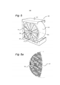
[0034] De acordo com um aspecto alternativo, uma roda de recu- peração de calor pode compreender uma matriz de troca de calor co- mo essa na forma de uma folha enrolada, a roda tendo um eixo geo- métrico alinhado com a direção de fluxo e ainda compreendendo um arranjo de ventilador para a passagem de um fluxo de ar na direção axial através da matriz, por meio do que as tiras são providas em sua superfície com um material dessecante. Neste contexto, é notado que um material dessecante é distinto de um material que é apenas de re- tenção de água pelo fato de poder reter água através de mecanismos adicionais higroscópicos ou químicos. Uma distinção pode ser feita, portanto, com materiais não dessecantes de retenção de água os quais retêm água meramente por fenômenos físicos ou de tensão su- perficial.[0034] According to an alternative aspect, a heat recovery wheel may comprise a heat exchange matrix like this in the form of a rolled sheet, the wheel having a geometrical axis aligned with the direction of flow and further comprising a fan arrangement for the passage of an air flow in the axial direction through the die, whereby the strips are provided on their surface with a desiccant material. In this context, it is noted that a desiccant material is distinct from a material that is only water retention in that it can retain water through additional hygroscopic or chemical mechanisms. A distinction can therefore be made with non-desiccant water retention materials which retain water merely by physical phenomena or surface tension.
[0035] Os recursos e as vantagens da invenção serão apreciados, mediante uma referência aos desenhos a seguir de um número de modalidades de exemplo, em que:[0035] The features and advantages of the invention will be appreciated, by reference to the following drawings in a number of example modalities, in which:
[0036] a figura 1 mostra um umidificador adiabático convencional;[0036] figure 1 shows a conventional adiabatic humidifier;
[0037] a figura 2 mostra uma vista detalhada de parte do dispositi- vo da figura 1;[0037] figure 2 shows a detailed view of part of the device of figure 1;
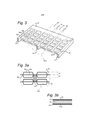
[0038] a figura 3 mostra uma porção de uma matriz de troca de calor de acordo com a presente invenção;[0038] figure 3 shows a portion of a heat exchange matrix according to the present invention;
[0039] a figura 3A mostra uma vista detalhada de parte da matriz da figura 3;[0039] figure 3A shows a detailed view of part of the matrix of figure 3;
[0040] a figura 3B mostra uma vista em seção transversal tomada na posição IIIb na figura 3A;[0040] figure 3B shows a cross-sectional view taken in position IIIb in figure 3A;
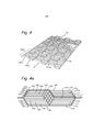
[0041] a figura 4 mostra uma folha de acordo com uma segunda modalidade da invenção;[0041] figure 4 shows a sheet according to a second embodiment of the invention;
[0042] a figura 4A mostra uma vista parcial da folha da figura 4 tomada na direção da seta A;[0042] figure 4A shows a partial view of the leaf of figure 4 taken in the direction of arrow A;
[0043] a figura 5 mostra uma modalidade da invenção na forma de uma roda de recuperação de calor;[0043] figure 5 shows an embodiment of the invention in the form of a heat recovery wheel;
[0044] a figura 5A mostra uma vista parcial da matriz da figura 5;[0044] figure 5A shows a partial view of the matrix of figure 5;
[0045] a figura 6 mostra uma modalidade da invenção como um elemento resfriador adiabático; e[0045] figure 6 shows an embodiment of the invention as an adiabatic cooling element; and
[0046] a figura 6A mostra uma vista parcial da matriz da figura 6.[0046] figure 6A shows a partial view of the matrix of figure 6.
[0047] A figura 1 mostra um arranjo de um umidificador adiabático convencional 1 disposto para a introdução de umidade em uma corren- te de ar S. O umidificador compreende uma matriz de troca de calor 2 suportada por um alojamento 4 que forma uma entrada 6 e uma saída 8 para a corrente de ar S. Mais ainda, é provido um controlador 10, um suprimento de água 12 e um ventilador 14.[0047] Figure 1 shows an arrangement of a conventional adiabatic humidifier 1 arranged for the introduction of moisture into an air stream S. The humidifier comprises a heat exchange matrix 2 supported by a housing 4 that forms an inlet 6 and an outlet 8 for the air stream S. Furthermore, a
[0048] A figura 2 mostra um detalhe de uma seção da matriz de troca de calor 2. Ela compreende uma pluralidade de camadas 20 de material corrugado compreendendo fibras de celulose impregnadas com resina. As camadas 20 são empilhadas em conjunto, por meio do que as corrugações 22 em camadas adjacentes cruzam com cada ou- tra em um ângulo formando passagens de fluxo 24. O passo das cor- rugações é de em torno de 25 mm.[0048] Figure 2 shows a detail of a section of the heat exchange matrix 2. It comprises a plurality of layers 20 of corrugated material comprising cellulose fibers impregnated with resin. The layers 20 are stacked together, whereby the corrugations 22 in adjacent layers intersect with each other at an angle forming flow passages 24. The corrugation pitch is around 25 mm.
[0049] Um umidificador 1 conforme mostrado na figura 1 e na figu- ra 2 pode ser usado para resfriamento de ar morno relativamente seco para perto de sua temperatura de bulbo úmido. Em uso, a corrente de ar S a ser resfriada é suprida para a entrada 6. Neste estágio, o ar po- de ter a temperatura T1 e tem baixo grau de umidade relativa RH1. A água é suprida para a matriz 2 pelo suprimento de água 12 fazendo com que o material de fibra das camadas 20 absorvam a umidade. Conforme a corrente de ar S passa através das passagens de fluxo 24, ela entranha a umidade das superfícies das camadas 20, a qual se evapora na corrente de ar S. Ao fazê-lo, a temperatura do ar é reduzi- da e seu grau de umidade relativa aumenta de modo conforme. A cor- rente de ar sai da matriz 2 com uma temperatura T2 e um grau de umidade relativa RH2. Se vapor de água suficiente for evaporado, o ar chegará a sua temperatura de bulbo úmido e estará plenamente satu- rado com um grau de umidade relativa de 100%. Embora não mostra- do, um eliminador de gotícula pode estar localizado a jusante da matriz2. de modo a se removerem gotículas de água finas que de outra for- ma podem estar entranhadas na corrente de ar S.[0049] A humidifier 1 as shown in figure 1 and figure 2 can be used for cooling relatively dry warm air to close to its wet bulb temperature. In use, the air stream S to be cooled is supplied to inlet 6. In this stage, the air can have a temperature of T1 and has a low relative humidity RH1. The water is supplied to the matrix 2 by the water supply 12 causing the fiber material of layers 20 to absorb moisture. As the air stream S passes through the flow passages 24, it entrains moisture from the surfaces of layers 20, which evaporates into the air stream S. In doing so, the air temperature is reduced and its degree relative humidity increases accordingly. The air current leaves matrix 2 with a temperature of T2 and a RH of RH2. If sufficient water vapor is evaporated, the air will reach its wet bulb temperature and be fully saturated with a relative humidity of 100%. Although not shown, a droplet eliminator can be located downstream of the matrix2. in order to remove fine water droplets that might otherwise be entrenched in the air stream S.
[0050] Os umidificadores convencionais, conforme descrito acima, são relativamente volumosos. De modo a se obter uma umidificação máxima, o comprimento na direção de fluxo geralmente está entre 200 mm e 300 mm, dependendo das condições típicas de grau de umidade de ar de entrada. A área frontal requerida é dependente da capacidade desejada, requerendo em torno de 0,14 m2 para cada 1000 m3/h.[0050] Conventional humidifiers, as described above, are relatively bulky. In order to obtain maximum humidification, the length in the flow direction is usually between 200 mm and 300 mm, depending on the typical conditions of the degree of humidity of the incoming air. The required frontal area is dependent on the desired capacity, requiring around 0.14 m2 for each 1000 m3 / h.
[0051] A figura 3 mostra uma porção de uma matriz de troca de calor 30 de acordo com a presente invenção. A matriz compreende uma primeira folha 32 e uma segunda folha 34. As folhas 32, 34, cada uma, definem um plano principal P tendo uma direção de fluxo F e uma direção transversal T. Em nome da descrição a seguir, uma regi- ão de borda não deformada das folhas será tomada como um nível de datum para o plano principal P. Cada folha é dividida em tiras 36, as quais são parcialmente separadas das folhas 32, 34 por cortes 38 e as quais são deslocadas do plano principal por uma distância de deslo- camento d.[0051] Figure 3 shows a portion of a heat exchange matrix 30 according to the present invention. The matrix comprises a
[0052] Na modalidade da figura 3, as tiras 36 estão localizadas em uma pluralidade de fileiras 40 alinhadas na direção de fluxo F. As tiras consecutivas em uma fileira 40 são projetadas como 36a, 36b e 36c. A figura 3A mostra uma vista da matriz 30 da figura 3 tomada na direção A. Conforme pode ser visto, as tiras 36a são deslocadas para três po- sições diferentes, especificamente, a posição zero (que fica no plano P) e para uma distância d1 acima do plano e uma distância d2 abaixo do plano. Cada tira 36 assim é separada de uma tira vizinha na dire- ção de fluxo F e deslocada do plano principal P por uma distância que é diferente daquela de sua vizinha.[0052] In the embodiment of figure 3, strips 36 are located in a plurality of
[0053] Entre cada fileira 40 está localizada uma zona sem tira 42 a qual também está no nível do plano principal P. Os espaçadores 44 estão localizados nas zonas sem tira 42, neste caso no centro e nas bordas da matriz. Os espaçadores 44 servem para se manterem as folhas 32 e 34 a uma distância uma da outra. Na presente modalidade, a distância d1 é de 2,0 mm, como o é a distância d2. A separação das folhas 32, 34 é de 6,0 mm. Mais ainda, a largura w de cada tira 36 me- dida na direção de fluxo F é de 2,0 mm e o comprimento l das tiras 36 é de 10 mm.[0053] Between each
[0054] A figura 3B mostra uma vista em seção transversal do ma- terial da folha 32 tomada na posição B na figura 3. Embora a folha 32 seja descrita, será entendido que a folha 34 é substancialmente idênti- ca. A folha 32 compreende uma camada primária 46 de alumínio reco- zido macio tendo uma espessura de 70 mícrons. Em cada superfície, a camada primária 48 é revestida com uma camada de proteção 50 de primer de PVC ou similar. A camada de proteção 50 também é um iso- lante de calor e pode ser usada para a junção de porções de folha em conjunto ou para outros elementos durante uma construção, se assim requerido. A camada mais externa em ambas as superfícies da folha 32 é uma camada de retenção de água 52. É notado que a espessura destas camadas é mostrada esquematicamente e elas podem variar em um fato real consideravelmente umas em relação às outras.[0054] Figure 3B shows a cross-sectional view of the material of
[0055] Um fator importante para a operação eficiente de um resfri- ador evaporativo é a natureza da camada de retenção de água 52. Embora uma referência seja feita a uma camada de retenção de água, é claramente entendido que a camada é de fato uma camada de re- tenção e liberação de água, sem a ligação dela quimicamente. Uma exigência de uma camada como essa é que ela facilmente proporcione sua água, de modo que uma resistência mínima à evaporação seja encontrada. Também é importante que ela distribua água de forma rá- pida e efetiva para todas as superfícies relevantes. Assim, deve ser hidrofílica sem ser higroscópica, preferencialmente retendo água pri- mariamente por efeitos de tensão superficial.[0055] An important factor for the efficient operation of an evaporative cooler is the nature of the water retention layer 52. Although a reference is made to a water retention layer, it is clearly understood that the layer is in fact a water retention and release layer, without chemically bonding it. A requirement for a layer like this is that it easily provides its water, so that minimal resistance to evaporation is found. It is also important that it distributes water quickly and effectively to all relevant surfaces. Thus, it must be hydrophilic without being hygroscopic, preferably retaining water primarily due to surface tension effects.
[0056] Na presente modalidade, a camada de retenção de água 52 é formada a partir de um material fibroso. Um material de exemplo pa- ra a formação da camada de retenção de água 30 é uma mescla a 50/50 de poliéster / viscose de 20 g/m2, disponível a partir de Lantor B.V. na Holanda. Um outro material de exemplo é uma fibra de poliés- ter revestida de poliamida de 30 g/m2 disponível segundo o nome Col- back™ a partir da Colbond N.V. na Holanda. Outros materiais tendo propriedades similares incluindo fibras sintéticas e naturais, tal como lã, também podem ser usados. Quando necessário, a camada de re- tenção de água 52 pode ser revestida ou de outra forma tratada para a provisão de propriedades antibacterianas ou outras anti-incrustação.[0056] In the present embodiment, the water retention layer 52 is formed from a fibrous material. An example material for forming the water retention layer 30 is a 50/50 blend of 20 g / m2 polyester / viscose, available from Lantor B.V. in the Netherlands. Another example material is a polyester fiber coated with 30 g / m2 polyamide available under the name Col- back ™ from Colbond N.V. in the Netherlands. Other materials having similar properties including synthetic and natural fibers, such as wool, can also be used. When necessary, the water retaining layer 52 can be coated or otherwise treated to provide antibacterial or other anti-fouling properties.
[0057] A camada de retenção de água 52 é afixada de forma ade- siva à camada de proteção 50 usando-se uma camada de 2 mícrons de adesivo de poliuretana de dois componentes. O laminado resultante mostrou ser ideal para as finalidades de fabricação, uma vez que pode ser formado e cortado no formato desejado em um processo contínuo, sem deslaminação substancial. Outras camadas de retenção de água, tal com de cimento Portland, também podem ser usadas e, de fato, mostraram prover propriedades superiores, embora, ainda, sua produ- ção seja mais complexa, uma vez que há uma tendência à fissuração ou à formação de flocos, se aplicadas antes da formação da matriz. Não obstante, acredita-se que outros acabamentos e tratamentos de superfície, tal como óxido de alumínio, possam em si ser adequadas para a provisão da retenção de água e de formação de mecha reque- ridas.[0057] The water retention layer 52 is affixed to the
[0058] Em uso, a matriz 30 pode ser provida em um bloco com- preendendo múltiplas camadas e pode estar localizada em um aloja- mento 4, conforme descrito em relação à figura 1, tomando o lugar da matriz convencional 2. De acordo com a invenção, o tamanho geral do alojamento para dados resfriamento e fluxo de ar pode ser reduzido ou, alternativamente, para um alojamento do mesmo tamanho, um flu- xo de ar consideravelmente maior pode ser provido.[0058] In use, the matrix 30 can be provided in a block comprising multiple layers and can be located in a housing 4, as described in relation to figure 1, taking the place of the conventional matrix 2. According to the invention, the general size of the housing for cooling and air flow data can be reduced or, alternatively, for a housing of the same size, a considerably larger air flow can be provided.
[0059] A figura 4 mostra uma segunda modalidade da invenção na qual números iguais precedidos com 100 são usados para a designa- ção de elementos similares para aqueles da primeira modalidade. A folha 132 define um plano principal P tendo uma direção de fluxo F e uma direção transversal T. Nesta modalidade, a folha 132 é dividida em tiras 136A-J separadas de cada outra na direção de fluxo F por cortes 138 e a partir de tiras adjacentes 136 na direção transversal T por zonas sem tira 142. Cada tira 136 tem um contorno corrugado que compreende uma primeira porção 135A-J deslocada para um lado do plano P e uma segunda porção 137A-J sendo deslocada para o lado oposto do plano ou estando no plano em si (deslocamento zero). De todo, as porções de tira 135, 137 são deslocadas para 9 posições dife- rentes com respeito ao plano principal P. Cada porção de tira 135, 137 é deslocada para uma posição diferente em relação a uma porção de tira vizinha 135, 137 na direção de fluxo F. O material de tira é o mes- mo que aquele descrito em relação à figura 3.[0059] Figure 4 shows a second embodiment of the invention in which equal numbers preceded by 100 are used to designate elements similar to those of the first embodiment.
[0060] A figura 4A mostra uma vista parcial de uma porção da fo- lha 132 da figura 4 tomada na direção de seta A, em que as porções de tira diferentes 135 A-J, 137 A-J podem ser claramente vistas. Como resultado das porções de tira 135, 137 serem deslocadas para posi- ções diferentes, pode ser obtido que cada uma das tiras 136 tenha o mesmo comprimento absoluto L que o medido ao longo de seu contor- no. Isto tem a vantagem de que, quando as tiras 136 são cortadas a partir de uma folha contínua, haverá relativamente pouca deformação geral da folha e as zonas sem tira 142 ficarão em uma linha reta.[0060] Figure 4A shows a partial view of a portion of the
[0061] A figura 5 expõe uma modalidade da invenção em que a folha 132 é proporcionada na forma de uma roda de recuperação de calor 60. A folha 132 é enrolada de uma forma contínua para a forma- ção de uma matriz 130 no formato de um rolo. A matriz 130 é suporta- da em um alojamento 104 para rotação por um motor 107. Um fluxo ocorre através da roda em ambas as direções para frente FF e reversa FR.[0061] Figure 5 shows an embodiment of the invention in which the
[0062] A figura 5A mostra uma vista parcial da matriz 130 da figura 5. Nesta modalidade, as camadas consecutivas da folha 132 ficam no topo de cada outra, sem espaçadores entre elas. Devido aos numero- sos deslocamentos diferentes das porções de tira 135, 137, as folhas 132 são efetivamente espaçadas de cada outra pela interação de por- ções de tira das camadas vizinhas. Pode ser notado, também, que as zonas sem tira 142 não ficam acima de cada outra, por meio do que a zona sem tira em cada camada adjacente forma um canal parcial para o fluxo de ar.[0062] Figure 5A shows a partial view of the
[0063] Mais ainda, na modalidade da figura 5A, a camada de re- tenção de água (não mostrada) é um revestimento dessecante do tipo geralmente usado para rodas dessecantes. Esta camada pode ser, por exemplo, uma zeólita de tipo X ou de tipo Y, sílica, alumina ou mesclas das mesmas tendo um comportamento isotérmico modificado ou qual- quer outro material adequado, conforme descrito para esta finalidade na US 5860284, cujo conteúdo é incorporado aqui como referência em sua totalidade. Em uso, a roda 160 da figura 5 pode operar da mesma maneira que uma roda dessecante convencional com a vantagem de uma queda de pressão relativamente mais baixa para um dado tama- nho de roda 160 e vazão.[0063] Furthermore, in the form of figure 5A, the water retaining layer (not shown) is a desiccant coating of the type generally used for desiccant wheels. This layer can be, for example, a type X or type Y zeolite, silica, alumina or mixtures thereof having a modified isothermal behavior or any other suitable material, as described for this purpose in US 5860284, the content of which is incorporated here as a reference in its entirety. In use, the
[0064] A figura 6 mostra uma modalidade da invenção como um elemento resfriador adiabático 201 compreendendo uma matriz 230, conforme descrito acima, retida por um alojamento 204. Um canal de distribuição de água 212 ao longo do lado de topo do elemento 201 supre água através de furos 213, a qual flui para baixo ao longo das tiras 236. A água pode ser suprida para o canal 212 por uma ou por outro sistema adequado. O fluxo de ar na direção de fluxo F ajuda no transporte da água através da matriz 230. Adicionalmente, a presença da camada de retenção de água cobrindo as folhas 232 encoraja a formação de mecha da água para todas as regiões da matriz 230. As folhas 232 são espaçadas de cada outra por pontos de material de es- paçamento 244 compreendendo uma espuma adesiva de PU.[0064] Figure 6 shows an embodiment of the invention as an
[0065] Uma matriz, conforme descrito acima de acordo com a figu- ra 4, foi construída e testada. Testes similares foram realizados em um material de matriz convencional CELDEK ™ 5090-15 disponível a par- tir de Munters AB. É notado que a área superficial do material por vo- lume unitário é comparável ao material. Os testes foram realizados de acordo com a Norma Australiana (AS 2913-2000), por meio do que o ar de suprimento tem uma temperatura de bulbo seco de 38 °C e uma temperatura de bulbo úmido de 21 °C (21% de grau de umidade relati- va). A eficiência de saturação é a redução de t real do ar de suprimen- to (Tin - Tout) com respeito à queda de temperatura que seria requeri- da para se atingir a temperatura de bulbo úmido (T wb in).[0065] A matrix, as described above according to figure 4, was built and tested. Similar tests were performed on a conventional CELDEK ™ 5090-15 matrix material available from Munters AB. It is noted that the surface area of the material per unit volume is comparable to the material. The tests were carried out according to the Australian Standard (AS 2913-2000), whereby the supply air has a dry bulb temperature of 38 ° C and a wet bulb temperature of 21 ° C (21% degree relative humidity). Saturation efficiency is the reduction of the actual t of the supply air (Tin - Tout) with respect to the temperature drop that would be required to reach the wet bulb temperature (T wb in).
[0066] Eficiência de Saturação = (Tin - Tout) / (Tin - T wb in).[0066] Saturation efficiency = (Tin - Tout) / (Tin - T wb in).
[0067] Os resultados dados na Tabela 1 abaixo mostram:[0067] The results given in Table 1 below show:
[0068] Para a mesma vazão e o mesmo volume que o exemplo, o material comparativo tem uma eficiência de bulbo úmido 9% mais bai- xa e uma queda de pressão 89% mais alta;[0068] For the same flow and the same volume as the example, the comparative material has a 9% lower wet bulb efficiency and an 89% higher pressure drop;
[0069] Se o comprimento do material comparativo for aumentado, de modo a se obter a mesma eficiência à mesma vazão como o exemplo, 44% a mais de material são requeridos e a queda de pres- são será 164% mais alta;[0069] If the length of the comparative material is increased, in order to obtain the same efficiency at the same flow as the example, 44% more material is required and the pressure drop will be 164% higher;
[0070] Com o mesmo comprimento como o exemplo, a vazão para o material comparativo deve ser reduzida para em torno de 1,8 m/s, de modo a se obter a mesma queda de pressão. Para isto, 39% a mais de volume de material são requeridos e a eficiência de bulbo úmido é 6% mais baixa;[0070] With the same length as the example, the flow for the comparative material must be reduced to around 1.8 m / s, in order to obtain the same pressure drop. For this, 39% more material volume is required and the wet bulb efficiency is 6% lower;
[0071] Se o comprimento do material comparativo for aumentado e a vazão ajustada de modo que a queda de pressão e a eficiência de bulbo úmido sejam comparáveis com aquelas do exemplo, 122% a mais de volume de material serão requeridos. Tabela 1
[0072] Assim, a invenção foi descrita com referência a certas mo- dalidades, conforme discutido acima. Será reconhecido que estas mo- dalidades são suscetíveis a várias modificações e formas alternativas bem conhecidas para aqueles de conhecimento na técnica.[0072] Thus, the invention has been described with reference to certain modalities, as discussed above. It will be recognized that these modalities are susceptible to various modifications and alternative forms well known to those of skill in the art.
[0073] Muitas modificações, além daquelas descritas acima podem ser feitas nas estruturas e nas técnicas descritas aqui, sem que se desvie do espírito e do escopo da invenção. Assim sendo, embora modalidades específicas tenham sido descritas, estas são exemplos apenas e não são limitantes para o escopo da invenção.[0073] Many modifications, in addition to those described above, can be made in the structures and techniques described here, without deviating from the spirit and scope of the invention. Therefore, although specific modalities have been described, these are examples only and are not limiting to the scope of the invention.
Claims (21)
Applications Claiming Priority (3)
| Application Number | Priority Date | Filing Date | Title |
|---|---|---|---|
| NL2007827 | 2011-11-21 | ||
| NL2007827A NL2007827C2 (en) | 2011-11-21 | 2011-11-21 | Heat exchange matrix. |
| PCT/NL2012/050830 WO2013095105A1 (en) | 2011-11-21 | 2012-11-21 | Heat exchange matrix |
Publications (3)
| Publication Number | Publication Date |
|---|---|
| BR112014012144A2 BR112014012144A2 (en) | 2017-06-13 |
| BR112014012144A8 BR112014012144A8 (en) | 2017-06-20 |
| BR112014012144B1 true BR112014012144B1 (en) | 2020-12-22 |
Family
ID=47722521
Family Applications (1)
| Application Number | Title | Priority Date | Filing Date |
|---|---|---|---|
| BR112014012144-3A BR112014012144B1 (en) | 2011-11-21 | 2012-11-21 | heat exchange matrix |
Country Status (13)
| Country | Link |
|---|---|
| US (1) | US9404689B2 (en) |
| EP (1) | EP2791608B1 (en) |
| JP (1) | JP6211526B2 (en) |
| KR (1) | KR102060704B1 (en) |
| CN (1) | CN104081148B (en) |
| AU (1) | AU2012354313B2 (en) |
| BR (1) | BR112014012144B1 (en) |
| ES (1) | ES2604712T3 (en) |
| IN (1) | IN2014CN04663A (en) |
| MX (1) | MX363494B (en) |
| NL (1) | NL2007827C2 (en) |
| WO (1) | WO2013095105A1 (en) |
| ZA (1) | ZA201404570B (en) |
Families Citing this family (11)
| Publication number | Priority date | Publication date | Assignee | Title |
|---|---|---|---|---|
| WO2016064684A1 (en) * | 2014-10-20 | 2016-04-28 | Numerical Design, Inc. | Microfluidic-based apparatus and method for vaporization of liquids |
| GB201612042D0 (en) | 2016-07-11 | 2016-08-24 | Oxycom Beheer Bv | Two stage cooler |
| WO2018126299A1 (en) * | 2017-01-09 | 2018-07-12 | Resmed Limited | A humidifier for a respiratory therapy device |
| US10539349B2 (en) | 2017-04-05 | 2020-01-21 | International Business Machines Corporation | Coiled adsorption heat exchanger |
| DE102017120658A1 (en) * | 2017-09-07 | 2019-03-07 | ENEXIO Water Technologies GmbH | trickling |
| SE543027C2 (en) * | 2017-10-13 | 2020-09-29 | Flexit Sverige Ab | Rotating heat exchanger with improved heat transfer capacity |
| CN108088000A (en) * | 2017-12-29 | 2018-05-29 | 姬晓青 | A kind of cool-down dehumidification equipment of medical inspection room |
| KR101923123B1 (en) * | 2018-09-05 | 2019-02-26 | 김수현 | evaporative cooler module and Air conditioning system Using the evaporative cooler module |
| US11041679B2 (en) * | 2019-01-21 | 2021-06-22 | Johnson Controls Technology Company | Energy recovery wheel assembly for an HVAC system |
| US20210381771A1 (en) * | 2020-04-23 | 2021-12-09 | Brentwood Industries, Inc. | Drift eliminator and method of making |
| SE2051118A1 (en) * | 2020-09-25 | 2022-03-26 | Heatex Ab | Web, web matrix, and rotor for heat exchanger |
Family Cites Families (29)
| Publication number | Priority date | Publication date | Assignee | Title |
|---|---|---|---|---|
| US2607437A (en) * | 1948-03-29 | 1952-08-19 | Garrett Corp | Apparatus for separating liquids and gases |
| SE302778B (en) | 1963-07-04 | 1968-08-05 | C Munters | |
| SE311371B (en) * | 1966-01-26 | 1969-06-09 | Munters C | |
| GB1158766A (en) * | 1967-05-24 | 1969-07-16 | Ronald Priestley | Apparatus for use in Effecting Contact of a Gas with a Flowing Liquid Film |
| AT313936B (en) * | 1969-07-14 | 1974-03-11 | Faigle Heinz | Trickle installation, especially for cooling towers |
| US3733063A (en) * | 1971-09-24 | 1973-05-15 | Marley Co | Chevron ribbed fill unit for water cooling tower |
| SE450166B (en) * | 1976-05-13 | 1987-06-09 | Munters Ab Carl | ROTATING REGENERATIVE MIXTURERS CONSISTING OF FOLDED LAYERS AND SETS AND APPARATUS FOR ITS MANUFACTURING |
| US4147210A (en) | 1976-08-03 | 1979-04-03 | Pronko Vladimir G | Screen heat exchanger |
| CH628730A5 (en) * | 1977-06-02 | 1982-03-15 | Alusuisse | STRIP FOR MAKING BODY FOR EXCHANGE OF SENSIBLE AND LATENT HEAT IN A REGENERATIVE HEAT EXCHANGER. |
| US4276242A (en) * | 1979-11-19 | 1981-06-30 | Koch Engineering Company, Inc. | Vapor-liquid contact grid apparatus |
| JPS6012088U (en) * | 1983-06-30 | 1985-01-26 | カルソニックカンセイ株式会社 | Heat exchanger |
| FR2580794B1 (en) * | 1985-04-23 | 1989-05-19 | Inst Francais Du Petrole | THERMAL EXCHANGE DEVICE, ESPECIALLY FOR GAS EXCHANGES |
| JPS6256786A (en) * | 1985-09-06 | 1987-03-12 | Hitachi Ltd | Heat exchanger |
| US4769053A (en) | 1987-03-26 | 1988-09-06 | Semco Mfg., Inc. | High efficiency sensible and latent heat exchange media with selected transfer for a total energy recovery wheel |
| JPH03134427A (en) * | 1989-10-20 | 1991-06-07 | Hitachi Ltd | Vaporization type humidifier element |
| JPH0439620U (en) * | 1990-08-03 | 1992-04-03 | ||
| US5749230A (en) * | 1991-01-18 | 1998-05-12 | Engelhard/Icc | Method for creating a humidity gradient within an air conditioned zone |
| GB2258524B (en) | 1991-08-08 | 1995-05-31 | Nat Power Plc | Film type packing element for use in cooling towers |
| US5143658A (en) | 1991-09-23 | 1992-09-01 | Munters Corporation | Alternating sheet evaporative cooling pad |
| US5204027A (en) * | 1992-02-04 | 1993-04-20 | Armstrong Charles M | Fluid contact panels |
| US5542968A (en) | 1995-01-24 | 1996-08-06 | Laroche Industries, Inc. | Enthalphy Wheel |
| US5860284A (en) | 1996-07-19 | 1999-01-19 | Novel Aire Technologies, L.L.C. | Thermally regenerated desiccant air conditioner with indirect evaporative cooler |
| JPH11148793A (en) * | 1997-11-14 | 1999-06-02 | Zexel:Kk | Method and device for forming fin used in integral heat exchanger |
| NL1021812C1 (en) | 2002-04-26 | 2003-10-28 | Oxycell Holding Bv | Dew point cooler. |
| NL1022799C2 (en) * | 2003-02-27 | 2004-08-30 | Oxycell Holding Bv | Dew point cooler with detachable irrigation means. |
| GB0517776D0 (en) * | 2005-09-01 | 2005-10-12 | Oxycell Holding Bv | Vapour extraction device |
| GB0622355D0 (en) * | 2006-11-09 | 2006-12-20 | Oxycell Holding Bv | High efficiency heat exchanger and dehumidifier |
| GB2455332A (en) * | 2007-12-05 | 2009-06-10 | Oxycom Beheer Bv | A combined heat exchange system supplying cooled air |
| US8322186B2 (en) * | 2008-05-23 | 2012-12-04 | Dana Canada Corporation | Turbulizers and method for forming same |
-
2011
- 2011-11-21 NL NL2007827A patent/NL2007827C2/en not_active IP Right Cessation
-
2012
- 2012-11-21 AU AU2012354313A patent/AU2012354313B2/en active Active
- 2012-11-21 US US14/359,674 patent/US9404689B2/en active Active
- 2012-11-21 MX MX2014006151A patent/MX363494B/en unknown
- 2012-11-21 KR KR1020147017231A patent/KR102060704B1/en active IP Right Grant
- 2012-11-21 EP EP12824827.5A patent/EP2791608B1/en active Active
- 2012-11-21 CN CN201280067671.9A patent/CN104081148B/en active Active
- 2012-11-21 IN IN4663CHN2014 patent/IN2014CN04663A/en unknown
- 2012-11-21 ES ES12824827.5T patent/ES2604712T3/en active Active
- 2012-11-21 BR BR112014012144-3A patent/BR112014012144B1/en active IP Right Grant
- 2012-11-21 WO PCT/NL2012/050830 patent/WO2013095105A1/en active Application Filing
- 2012-11-21 JP JP2014543442A patent/JP6211526B2/en active Active
-
2014
- 2014-06-20 ZA ZA2014/04570A patent/ZA201404570B/en unknown
Also Published As
| Publication number | Publication date |
|---|---|
| EP2791608A1 (en) | 2014-10-22 |
| JP2014533821A (en) | 2014-12-15 |
| AU2012354313A1 (en) | 2014-07-17 |
| IN2014CN04663A (en) | 2015-09-18 |
| NL2007827C2 (en) | 2013-05-23 |
| KR102060704B1 (en) | 2019-12-30 |
| US9404689B2 (en) | 2016-08-02 |
| KR20160033573A (en) | 2016-03-28 |
| MX363494B (en) | 2019-03-26 |
| AU2012354313B2 (en) | 2017-10-12 |
| BR112014012144A8 (en) | 2017-06-20 |
| ES2604712T3 (en) | 2017-03-08 |
| CN104081148B (en) | 2017-03-15 |
| ZA201404570B (en) | 2015-09-30 |
| BR112014012144A2 (en) | 2017-06-13 |
| US20140352345A1 (en) | 2014-12-04 |
| CN104081148A (en) | 2014-10-01 |
| MX2014006151A (en) | 2014-08-27 |
| WO2013095105A1 (en) | 2013-06-27 |
| EP2791608B1 (en) | 2016-09-14 |
| JP6211526B2 (en) | 2017-10-11 |
Similar Documents
| Publication | Publication Date | Title |
|---|---|---|
| BR112014012144B1 (en) | heat exchange matrix | |
| US9140471B2 (en) | Indirect evaporative coolers with enhanced heat transfer | |
| TWI421462B (en) | High efficiency heat exchanger and dehumidifier | |
| US11906199B2 (en) | Enthalpy exchanger | |
| CA2594528C (en) | Method and materials for improving evaporative heat exchangers | |
| JP2008070070A (en) | Total heat exchanger | |
| AU2006206035B2 (en) | Method and materials for improving evaporative heat exchangers | |
| CN202350284U (en) | Total heat exchange unit | |
| KR20200102664A (en) | Heat Exchange Element Having Hole In Spacers | |
| CN102410618A (en) | Full heat exchange unit |
Legal Events
| Date | Code | Title | Description |
|---|---|---|---|
| B06F | Objections, documents and/or translations needed after an examination request according [chapter 6.6 patent gazette] | ||
| B06U | Preliminary requirement: requests with searches performed by other patent offices: procedure suspended [chapter 6.21 patent gazette] | ||
| B09A | Decision: intention to grant [chapter 9.1 patent gazette] | ||
| B16A | Patent or certificate of addition of invention granted [chapter 16.1 patent gazette] |
Free format text: PRAZO DE VALIDADE: 20 (VINTE) ANOS CONTADOS A PARTIR DE 21/11/2012, OBSERVADAS AS CONDICOES LEGAIS. |