EP4001710A1 - Flow rate adjusting valve - Google Patents
Flow rate adjusting valve Download PDFInfo
- Publication number
- EP4001710A1 EP4001710A1 EP21207072.6A EP21207072A EP4001710A1 EP 4001710 A1 EP4001710 A1 EP 4001710A1 EP 21207072 A EP21207072 A EP 21207072A EP 4001710 A1 EP4001710 A1 EP 4001710A1
- Authority
- EP
- European Patent Office
- Prior art keywords
- handle
- flow rate
- splines
- rate adjusting
- valve
- Prior art date
- Legal status (The legal status is an assumption and is not a legal conclusion. Google has not performed a legal analysis and makes no representation as to the accuracy of the status listed.)
- Granted
Links
Images



Classifications
-
- F—MECHANICAL ENGINEERING; LIGHTING; HEATING; WEAPONS; BLASTING
- F16—ENGINEERING ELEMENTS AND UNITS; GENERAL MEASURES FOR PRODUCING AND MAINTAINING EFFECTIVE FUNCTIONING OF MACHINES OR INSTALLATIONS; THERMAL INSULATION IN GENERAL
- F16K—VALVES; TAPS; COCKS; ACTUATING-FLOATS; DEVICES FOR VENTING OR AERATING
- F16K1/00—Lift valves or globe valves, i.e. cut-off apparatus with closure members having at least a component of their opening and closing motion perpendicular to the closing faces
- F16K1/32—Details
- F16K1/34—Cutting-off parts, e.g. valve members, seats
- F16K1/36—Valve members
- F16K1/38—Valve members of conical shape
-
- F—MECHANICAL ENGINEERING; LIGHTING; HEATING; WEAPONS; BLASTING
- F16—ENGINEERING ELEMENTS AND UNITS; GENERAL MEASURES FOR PRODUCING AND MAINTAINING EFFECTIVE FUNCTIONING OF MACHINES OR INSTALLATIONS; THERMAL INSULATION IN GENERAL
- F16K—VALVES; TAPS; COCKS; ACTUATING-FLOATS; DEVICES FOR VENTING OR AERATING
- F16K31/00—Actuating devices; Operating means; Releasing devices
- F16K31/44—Mechanical actuating means
- F16K31/60—Handles
-
- F—MECHANICAL ENGINEERING; LIGHTING; HEATING; WEAPONS; BLASTING
- F16—ENGINEERING ELEMENTS AND UNITS; GENERAL MEASURES FOR PRODUCING AND MAINTAINING EFFECTIVE FUNCTIONING OF MACHINES OR INSTALLATIONS; THERMAL INSULATION IN GENERAL
- F16K—VALVES; TAPS; COCKS; ACTUATING-FLOATS; DEVICES FOR VENTING OR AERATING
- F16K3/00—Gate valves or sliding valves, i.e. cut-off apparatus with closing members having a sliding movement along the seat for opening and closing
- F16K3/22—Gate valves or sliding valves, i.e. cut-off apparatus with closing members having a sliding movement along the seat for opening and closing with sealing faces shaped as surfaces of solids of revolution
- F16K3/24—Gate valves or sliding valves, i.e. cut-off apparatus with closing members having a sliding movement along the seat for opening and closing with sealing faces shaped as surfaces of solids of revolution with cylindrical valve members
- F16K3/246—Combination of a sliding valve and a lift valve
-
- F—MECHANICAL ENGINEERING; LIGHTING; HEATING; WEAPONS; BLASTING
- F16—ENGINEERING ELEMENTS AND UNITS; GENERAL MEASURES FOR PRODUCING AND MAINTAINING EFFECTIVE FUNCTIONING OF MACHINES OR INSTALLATIONS; THERMAL INSULATION IN GENERAL
- F16K—VALVES; TAPS; COCKS; ACTUATING-FLOATS; DEVICES FOR VENTING OR AERATING
- F16K1/00—Lift valves or globe valves, i.e. cut-off apparatus with closure members having at least a component of their opening and closing motion perpendicular to the closing faces
- F16K1/32—Details
- F16K1/34—Cutting-off parts, e.g. valve members, seats
- F16K1/36—Valve members
-
- F—MECHANICAL ENGINEERING; LIGHTING; HEATING; WEAPONS; BLASTING
- F16—ENGINEERING ELEMENTS AND UNITS; GENERAL MEASURES FOR PRODUCING AND MAINTAINING EFFECTIVE FUNCTIONING OF MACHINES OR INSTALLATIONS; THERMAL INSULATION IN GENERAL
- F16K—VALVES; TAPS; COCKS; ACTUATING-FLOATS; DEVICES FOR VENTING OR AERATING
- F16K1/00—Lift valves or globe valves, i.e. cut-off apparatus with closure members having at least a component of their opening and closing motion perpendicular to the closing faces
- F16K1/32—Details
- F16K1/52—Means for additional adjustment of the rate of flow
-
- F—MECHANICAL ENGINEERING; LIGHTING; HEATING; WEAPONS; BLASTING
- F16—ENGINEERING ELEMENTS AND UNITS; GENERAL MEASURES FOR PRODUCING AND MAINTAINING EFFECTIVE FUNCTIONING OF MACHINES OR INSTALLATIONS; THERMAL INSULATION IN GENERAL
- F16K—VALVES; TAPS; COCKS; ACTUATING-FLOATS; DEVICES FOR VENTING OR AERATING
- F16K3/00—Gate valves or sliding valves, i.e. cut-off apparatus with closing members having a sliding movement along the seat for opening and closing
- F16K3/30—Details
- F16K3/314—Forms or constructions of slides; Attachment of the slide to the spindle
-
- F—MECHANICAL ENGINEERING; LIGHTING; HEATING; WEAPONS; BLASTING
- F16—ENGINEERING ELEMENTS AND UNITS; GENERAL MEASURES FOR PRODUCING AND MAINTAINING EFFECTIVE FUNCTIONING OF MACHINES OR INSTALLATIONS; THERMAL INSULATION IN GENERAL
- F16K—VALVES; TAPS; COCKS; ACTUATING-FLOATS; DEVICES FOR VENTING OR AERATING
- F16K31/00—Actuating devices; Operating means; Releasing devices
- F16K31/02—Actuating devices; Operating means; Releasing devices electric; magnetic
- F16K31/04—Actuating devices; Operating means; Releasing devices electric; magnetic using a motor
-
- F—MECHANICAL ENGINEERING; LIGHTING; HEATING; WEAPONS; BLASTING
- F16—ENGINEERING ELEMENTS AND UNITS; GENERAL MEASURES FOR PRODUCING AND MAINTAINING EFFECTIVE FUNCTIONING OF MACHINES OR INSTALLATIONS; THERMAL INSULATION IN GENERAL
- F16K—VALVES; TAPS; COCKS; ACTUATING-FLOATS; DEVICES FOR VENTING OR AERATING
- F16K31/00—Actuating devices; Operating means; Releasing devices
- F16K31/02—Actuating devices; Operating means; Releasing devices electric; magnetic
- F16K31/04—Actuating devices; Operating means; Releasing devices electric; magnetic using a motor
- F16K31/05—Actuating devices; Operating means; Releasing devices electric; magnetic using a motor specially adapted for operating hand-operated valves or for combined motor and hand operation
-
- F—MECHANICAL ENGINEERING; LIGHTING; HEATING; WEAPONS; BLASTING
- F16—ENGINEERING ELEMENTS AND UNITS; GENERAL MEASURES FOR PRODUCING AND MAINTAINING EFFECTIVE FUNCTIONING OF MACHINES OR INSTALLATIONS; THERMAL INSULATION IN GENERAL
- F16K—VALVES; TAPS; COCKS; ACTUATING-FLOATS; DEVICES FOR VENTING OR AERATING
- F16K31/00—Actuating devices; Operating means; Releasing devices
- F16K31/44—Mechanical actuating means
- F16K31/50—Mechanical actuating means with screw-spindle or internally threaded actuating means
-
- F—MECHANICAL ENGINEERING; LIGHTING; HEATING; WEAPONS; BLASTING
- F16—ENGINEERING ELEMENTS AND UNITS; GENERAL MEASURES FOR PRODUCING AND MAINTAINING EFFECTIVE FUNCTIONING OF MACHINES OR INSTALLATIONS; THERMAL INSULATION IN GENERAL
- F16K—VALVES; TAPS; COCKS; ACTUATING-FLOATS; DEVICES FOR VENTING OR AERATING
- F16K31/00—Actuating devices; Operating means; Releasing devices
- F16K31/44—Mechanical actuating means
- F16K31/53—Mechanical actuating means with toothed gearing
-
- F—MECHANICAL ENGINEERING; LIGHTING; HEATING; WEAPONS; BLASTING
- F16—ENGINEERING ELEMENTS AND UNITS; GENERAL MEASURES FOR PRODUCING AND MAINTAINING EFFECTIVE FUNCTIONING OF MACHINES OR INSTALLATIONS; THERMAL INSULATION IN GENERAL
- F16K—VALVES; TAPS; COCKS; ACTUATING-FLOATS; DEVICES FOR VENTING OR AERATING
- F16K35/00—Means to prevent accidental or unauthorised actuation
- F16K35/02—Means to prevent accidental or unauthorised actuation to be locked or disconnected by means of a pushing or pulling action
- F16K35/027—Means to prevent accidental or unauthorised actuation to be locked or disconnected by means of a pushing or pulling action the locking mechanism being actuated by pushing or pulling the valve actuator, the valve actuator being rotated subsequently to bring the valve closure element in the desired position
Definitions
- the present invention relates to a flow rate adjusting valve that adjusts a flow rate in a fluid passage.
- a flow rate adjusting valve (speed controller) that is capable of adjusting a flow path area by a manual operation.
- the flow rate adjusting valve is disposed, for example, in a flow path connecting a fluid pressure cylinder and a fluid supply source, or in a flow path connecting the fluid pressure cylinder and a discharge port.
- an electric needle valve is also known in which a valve opening degree is adjusted by an electric motor, so as to enable the flow rate of a fluid supplied to an actuator to be remotely controlled.
- a flow rate adjusting valve is one in which a needle valve is arranged so as to face a fluid passage of a main body, the flow rate adjusting valve including a handle configured to enable a rotational operation to be performed manually, an electric motor configured to be operated remotely, and a motive power transmission mechanism configured to selectively switch between a rotational operating force of the handle and a driving force of the electric motor, and to transmit the force to the needle valve, wherein the switching is performed by causing the handle to be moved in a direction of an axis of rotation.
- the flow rate adjusting valve according to the present invention is also equipped with a motive power transmission mechanism that selectively switches between the rotational operating force of the handle and the driving force of the electric motor, and transmits the selected force to the needle valve. Therefore, regardless of the specifications of the electric motor, manual operation of the handle can be easily realized, and the safety of on-site workers is assured. Further, since the aforementioned switching can be performed by a push-pull operation of causing the handle to be moved in the direction of the axis of rotation, ease of operation is satisfactory.
- a flow rate adjusting valve 10 is used to adjust the flow rate of a fluid such as compressed air or the like.
- a fluid such as compressed air or the like.
- the flow rate adjusting valve 10 includes a main body 12, a cover 14, a valve seat body 28, a needle valve 34, a handle 56, a stepping motor (electric motor) 58, and a motive power transmission mechanism.
- the motive power transmission mechanism is a mechanism that selectively switches between a rotational operating force of the handle 56 and a driving force of the stepping motor 58, and transmits the selected force to the needle valve 34. Details of the motive power transmission mechanism will be described later.
- the stepping motor 58 has a non-illustrated speed reducing gear incorporated therein. According to the present embodiment, the stepping motor 58 is used as the electric motor, but other types of electric motors may also be used.
- the box-shaped main body 12 includes an accommodating chamber 40 in which the stepping motor 58 and the motive power transmission mechanism are accommodated in cooperation with the cover 14.
- the cover 14 is attached to a support frame 60, which will be described later.
- An upper surface of the cover 14 is recessed downward at a position in proximity to a central location thereof in the longitudinal direction.
- the center of a bottomed surface of a recess 14a is open.
- a tubular handle supporting member 16 that rises upwardly from an open edge of the recess 14a is provided integrally with the cover 14.
- a lower part of the main body 12 includes a fluid passage 18 both ends of which are open, and which extends in a left and right direction.
- a first port 20 that opens on one end of the fluid passage 18, and a second port 22 that opens on another end of the fluid passage 18 are respectively connected to non-illustrated external pipes.
- a configuration is provided so that, by action of a later-described check valve 30, the flow rate can be adjusted when the fluid flows from the first port 20 toward the second port 22.
- the valve seat body 28 and the needle valve 34 are arranged in a manner so as to intersect the fluid passage 18.
- a cylindrical shaped guide wall 24 for guiding the fluid is arranged at a central location of the fluid passage 18 in the longitudinal direction.
- a central axis of the guide wall 24 is aligned with a central axis of the valve seat body 28 and the needle valve 34.
- the guide wall 24 includes a first window portion 24a, which is formed at an upper location of a portion of the guide wall that is closer to the first port 20.
- the guide wall 24 includes a second window portion 24b, which is formed at a lower location of a portion of the guide wall that is closer to the second port 22.
- the first port 20 is connected to the second port 22 via the first window portion 24a and the second window portion 24b.
- the guide wall 24 extends into the accommodating chamber 40, and the extended portion thereof constitutes a supporting wall 26 that supports the valve seat body 28.
- the tubular valve seat body 28 includes a supporting portion 28a, which is positioned at a central location of the valve seat body in the longitudinal direction.
- the supporting portion 28a is fitted and fixed to an inner side of the supporting wall 26 of the main body 12.
- the needle valve 34 is inserted and arranged so as to be capable of moving in the X direction, which is the axial direction thereof.
- a distal end of the needle valve 34 faces toward the fluid passage 18.
- the outer circumference of a portion of the needle valve 34 that is in proximity to a distal end of the needle valve has a tapered surface 34a.
- a more downward location than the supporting portion 28a of the valve seat body 28 includes a plurality of lateral holes 28b that penetrate through the side wall of the valve seat body 28.
- the valve seat body 28 further includes a valve seat 28c at a more downward location than the lateral holes 28b.
- the valve seat is capable of abutting against the tapered surface 34a of the needle valve 34.
- the first window portion 24a communicates with the second window portion 24b via the lateral holes 28b of the valve seat body 28 and a lower end opening 28e of the valve seat body 28. As shown in FIG.
- the check valve 30 prevents the fluid from flowing from the first window portion 24a to the second window portion 24b through a gap between the lower end part of the valve seat body 28 and the guide wall 24.
- the check valve 30 allows the fluid to flow through the aforementioned gap from the second window portion 24b to the first window portion 24a.
- a cylindrical collar 38 that supports an upper end part of the needle valve 34 is fixed to an inner surface of the valve seat body 28 at a more upward location than the supporting portion 28a.
- An outer circumference of the needle valve 34 and an inner circumference of the collar 38 are equipped with two sets of flat surfaces 34c and 38a that abut against one another. Consequently, the needle valve 34 is supported by the collar 38, in a manner so that rotation about a central axis is restricted, together with the needle valve 34 being capable of moving in the axial direction.
- the two sets of flat surfaces are used as a means for preventing the needle valve 34 from rotating with respect to the collar 38.
- a means such as a set of flat surface portions (D-cuts), splines, or the like may also be used.
- An annular seal member 32 which abuts against an inner circumference of the supporting wall 26 of the main body 12, is mounted on an outer circumference of the supporting portion 28a of the valve seat body 28.
- an annular needle packing 36 which is placed in sliding contact with an inner circumference of the supporting portion 28a of the valve seat body 28, is mounted on the outer circumference of the needle valve 34.
- the fluid passage 18 is separated in an airtight manner from the accommodating chamber 40 by the seal member 32 and the needle packing 36. Since the needle valve 34 is formed with a structure in which rotation about the central axis does not take place, the load applied to the needle packing 36 is reduced, and the durability of the needle packing 36 is enhanced.
- the motive power transmission mechanism includes a feed screw 42, a stem 44, a handle holder 46, a valve gear 48, and a motor gear 50.
- the rotational operating force of the handle 56 is transmitted to the needle valve 34 via the handle holder 46, the stem 44, and the feed screw 42.
- the driving force of the stepping motor 58 is transmitted to the needle valve 34 via the motor gear 50, the valve gear 48, the stem 44, and the feed screw 42.
- the motive power transmission path between the handle 56 and the needle valve 34 is constituted by the handle holder 46, the stem 44, and the feed screw 42.
- the motive power transmission path between the stepping motor 58 and the needle valve 34 is constituted by the motor gear 50, the valve gear 48, the stem 44, and the feed screw 42.
- the feed screw 42 includes a flange 42a in a central location thereof in the longitudinal direction, and further includes a male screw 42b on an outer circumference at a more downward location than the flange 42a.
- the feed screw 42 is rotatably supported by a bearing 52 provided on an upper end opening 28d of the valve seat body 28, at a more upward location than the flange 42a.
- An upper end of the feed screw 42 projects upwardly from the bearing 52, and is fitted on an inner side of a later-described cylindrical portion 44b of the stem 44.
- the needle valve 34 includes a bottomed screw hole 34b that opens at the upper end of the needle valve 34.
- a lower portion of the feed screw 42 is screwed-engaged with the screw hole 34b.
- the flange 42a of the feed screw 42 is arranged in a manner of being sandwiched between a lower surface of the bearing 52 and an upper surface of the collar 38. Consequently, movement of the feed screw 42 in the X direction, which is the axial direction, is restricted.
- the needle valve 34 the rotation of which about the central axis is restricted, moves in the axial direction.
- the stem 44 includes a plate-shaped flange portion 44a that extends in a horizontal direction, a cylindrical portion 44b extending downward from the flange portion 44a and the distal end of which is open, and a protruding portion 44c that protrudes upwardly from the flange portion 44a.
- the cylindrical portion 44b of the stem 44 is connected to the upper end part of the feed screw 42 by a predetermined means for preventing rotation. Consequently, the feed screw 42 rotates integrally with the stem 44, and the stem 44 is capable of moving relative to the feed screw 42 in the X direction, which is the axial direction.
- two sets of flat surface portions are used as the means for preventing rotation, but one set of flat surface portions (D-cuts), splines, or the like may also be used.
- the handle 56 includes an annular seat portion 56a, an outer tubular portion 56b extending downward from an outer circumferential part of the seat portion 56a, and an inner tubular portion 56c extending downward from an inner circumferential part of the seat portion 56a.
- a lower end of the outer tubular portion 56b is equipped with a rib 56d that projects inwardly in the radial direction.
- a lower end of the inner tubular portion 56c is equipped with a flange 56e that extends inwardly in the radial direction.
- an inner circumference of the inner tubular portion 56c in proximity to the lower end is provided with first splines 56f that engage with the splines 46a of the handle holder 46.
- an outer circumference of the inner tubular portion 56c in proximity to the upper end is provided with second splines 56g that engage with splines 16d provided on the inner circumference of the handle supporting member 16 of the cover 14.
- the handle 56 is capable of being subjected to a push-pull operation, and is capable of moving in the X direction (upper and lower direction), which is the direction of the axis of rotation thereof, between the upper limit position (upward end of movement) and the lower limit position (downward end of movement) as will be discussed below.
- the X direction upper and lower direction
- the flange portion 44a of the stem 44 which moves integrally with the handle holder 46 abuts against the step portion 16a of the handle supporting member 16.
- the handle 56 arrives at the upper limit position (see FIG. 4 ).
- the handle supporting member 16 enters into a space between the inner tubular portion 56c and the outer tubular portion 56b of the handle 56.
- the handle 56 arrives at the lower limit position (see FIG. 1 ).
- the handle 56 protrudes significantly upward from the cover 14, whereby the rotational operation becomes easy to perform.
- the handle 56 enters into the recess 14a of the cover 14.
- the handle 56 When the handle 56 is moved upward (in a first direction), the first splines 56f of the inner tubular portion 56c engage with the splines 46a of the handle holder 46. As a result, the handle 56, the handle holder 46, and the stem 44 can be rotated together in an integral manner. Further, when the handle 56 is moved to the upper limit position, engagement between the second splines 56g of the inner tubular portion 56c and the splines 16d of the handle supporting member 16 is released.
- the outer circumference of the handle supporting member 16 of the cover 14 is equipped with a first rib 16b and a second rib 16c that are arranged at a predetermined interval in the vertical direction.
- the first rib 16b and the second rib 16c engage with the rib 56d of the outer tubular portion 56b of the handle 56.
- the rib 56d of the handle 56 snap-engages with the first rib 16b of the handle supporting member 16.
- the handle 56d of the handle 56 snap-engages with the second rib 16c of the handle supporting member 16. Accordingly, unless an external force is applied thereto, the handle 56 that has reached the upper limit position or the lower limit position is stably retained at the upper limit position or the lower limit position.
- the support frame 60 which serves to support the stepping motor 58 is arranged in the horizontal direction.
- the support frame 60 is attached to the main body 12 by a non-illustrated fixing means.
- the valve gear 48 enmeshes with the motor gear 50 that is attached to an output shaft 58a of the stepping motor 58, and rotates in conjunction with the output shaft 58a of the stepping motor 58.
- the valve gear 48 and the motor gear 50 are arranged on an upper surface of the support frame 60.
- the valve gear 48 is made up from a gear portion 48a having teeth on the outer circumference thereof, and a shaft portion 48b that protrudes downward from the gear portion 48a.
- the gear portion 48a and the shaft portion 48b include a central hole 48c that penetrates in the X direction, which is the axial direction thereof.
- An inner circumference of the gear portion 48a is equipped with the splines 48d that engage with the splines 44d of the stem 44 (see FIG. 4 ).
- the support frame 60 includes an insertion hole 60a into which the feed screw 42 and the stem 44 are inserted.
- An upper part of the insertion hole 60a is formed with an enlarged diameter that serves as a first recess 60b for supporting the shaft portion 48b of the valve gear 48.
- a lower part of the insertion hole 60a has a diameter that is enlarged stepwise, and forms a second recess 60c into which the upper end part of the valve seat body 28 is inserted.
- the shaft portion 48b of the valve gear 48 is inserted into the first recess 60b.
- a convex portion 48e provided on an upper surface of the gear portion 48a abuts against the cover 14.
- valve gear 48 is supported so as to be capable of rotating about the central axis, while movement thereof in the X direction, which is the axial direction, is restricted.
- the support frame 60 is positioned in the interior of the accommodating chamber 40 by fitting the upper end part of the valve seat body 28 into the second recess 60c of the support frame 60.
- the cylindrical portion 44b of the stem 44 is inserted into the central hole 48c of the valve gear 48 and the insertion hole 60a of the support frame 60.
- the stem 44 is moved downward by pushing down on the handle 56, the splines 44d of the stem 44 engage with the splines 48d of the valve gear 48. Consequently, the driving force of the stepping motor 58 is transmitted to the feed screw 42 via the motor gear 50, the valve gear 48, and the stem 44.
- the stem 44 is moved upward by pulling the handle 56 upward, engagement between the splines 44d of the stem 44 and the splines 48d of the valve gear 48 is released.
- a circuit board 62 which is perpendicular with respect to the support frame 60, is disposed in the accommodating chamber 40. Electronic components in order to drive the stepping motor 58 are mounted on the circuit board 62. Needle-shaped terminals 64 that are erected on the circuit board 62 extend to the inner side of a tubular connector portion 66 provided on a side surface of the main body 12. Non-illustrated wirings are provided between the circuit board 62 and the stepping motor 58. The stepping motor 58 is driven by a remote control signal supplied from the terminals 64.
- the flow rate adjusting valve 10 is configured in the manner described above.
- descriptions will be given concerning a case in which the valve opening degree is adjusted by remote control, and a case in which the valve opening degree is manually adjusted.
- the state in which the handle 56 is in the upper limit position is regarded as an initial state.
- the handle 56 For driving the stepping motor 58 by remote control to thereby adjust the valve opening degree, the handle 56, which is at the upper limit position, is pushed down to the lower limit position. As shown in FIG. 5 , when the handle 56 is pushed downward, initially, the engagement between the first splines 56f of the inner tubular portion 56c of the handle 56 and the splines 46a of the handle holder 46 is released, and the stem 44, which is integral with the handle holder 46, is released from the connected state with the handle 56. More specifically, the motive power transmission path between the handle 56 and the needle valve 34 is interrupted midway, i.e., interrupted between the handle 56 and the handle holder 46.
- an appropriate frictional force is applied at a location where the upper end part of the feed screw 42 is fitted into the cylindrical portion 44b of the stem 44, or alternatively, at a location where the cylindrical portion 44b of the stem 44 is inserted through the central hole 48c of the valve gear 48. Therefore, when the handle 56 is pushed down, the stem 44 does not move downward immediately.
- the second splines 56g of the inner tubular portion 56c of the handle 56 start to engage with the splines 16d of the handle supporting member 16, and a state is brought about in which rotation of the handle 56 is prevented.
- the stem 44 is pushed down by the flange 56e of the handle 56, and the splines 44d of the stem 44 engage with the splines 48d of the valve gear 48 (see FIG. 1 ). Consequently, a state is brought about in which the driving force of the stepping motor 58 is capable of being transmitted to the needle valve 34 via the motor gear 50, the valve gear 48, the stem 44, and the feed screw 42. More specifically, the motive power transmission path between the stepping motor 58 and the needle valve 34 becomes continuous.
- the handle 56 when the handle 56 is pushed down, a state is brought about in which the motive power transmission path between the handle 56 and the needle valve 34 is interrupted midway and rotation of the handle 56 is prevented. If the handle 56 is further pushed down to the lower limit position, the motive power transmission path between the stepping motor 58 and the needle valve 34 becomes continuous. In such a state, the stepping motor 58 can be driven by remote control, thereby causing the needle valve 34 to be moved in the axial direction, and enabling the valve opening degree to be adjusted.
- the handle 56 which is at the lower limit position is pulled upward to the upper limit position.
- the first splines 56f of the inner tubular portion 56c engage with the splines 46a of the handle holder 46, and the three constituent elements, i.e., the handle 56, the handle holder 46, and the stem 44, are integrally connected in the direction of rotation. Owing to this feature, the motive power transmission path between the handle 56 and the needle valve 34 becomes continuous.
- the needle valve 34 can be moved in the axial direction via the handle holder 46, the stem 44, and the feed screw 42, and the valve opening degree can be adjusted.
- the motive power transmission mechanism that selectively switches between the rotational operating force of the handle 56 and the driving force of the stepping motor 58, and transmits the selected force to the needle valve 34. Therefore, regardless of the specifications of the stepping motor 58, manual operation of the handle can be easily realized, and the safety of on-site workers is assured. Further, since the aforementioned switching can be performed by a push-pull operation of causing the handle 56 to be moved in the direction of the axis of rotation, ease of operation is satisfactory.
Landscapes
- Engineering & Computer Science (AREA)
- General Engineering & Computer Science (AREA)
- Mechanical Engineering (AREA)
- Electrically Driven Valve-Operating Means (AREA)
- Mechanically-Actuated Valves (AREA)
Abstract
Description
- The present invention relates to a flow rate adjusting valve that adjusts a flow rate in a fluid passage.
- Conventionally, as a means for adjusting the speed of a fluid pressure cylinder, a flow rate adjusting valve (speed controller) that is capable of adjusting a flow path area by a manual operation has been known. The flow rate adjusting valve is disposed, for example, in a flow path connecting a fluid pressure cylinder and a fluid supply source, or in a flow path connecting the fluid pressure cylinder and a discharge port.
- Further, as shown in
JP 5061258 B2 - Even in the case of such a flow rate adjusting valve in which the valve opening degree is adjusted by driving an electric motor by remote control, when the equipment is started up, it is necessary to manually adjust the degree of the valve opening, and to confirm operation of the equipment or the like. In general, an assembly process of the production equipment is carried out by a procedure of assembling a machine body, providing pneumatic piping and electrical wiring, and downloading a program to a PLC or the like. Remote control signals can be transmitted to the electric motor only after downloading of the program has been completed. Confirmation of operations while the equipment is being driven must be carried out at an earlier stage, and at that time, such a confirmation must be performed manually.
- Further, in the case of remote control via a PLC, a system operator or a software engineer is generally required. There are also cases in which a person performing maintenance of the equipment does not possess the necessary capability to operate the equipment remotely. If the degree of opening of the flow rate adjusting valve cannot be adjusted manually, cooperation of a system operator or a software engineer must be sought, which is troublesome and time consuming.
- Of course, it is possible to provide a manual operating unit for the flow rate adjusting valve that drives the electric motor to adjust the valve opening degree. However, in the case of using a small-scale electric motor equipped with a speed reducing gear having a large speed reducing ratio, in a state in which the operating unit is connected to the electric motor on a driven side of the speed reducing gear, a situation occurs in which manual operation thereof is difficult.
- As described above, there is a demand for a flow rate adjusting valve in which a valve opening degree is capable of being adjusted both manually and by an electric motor. However, practical implementations thereof have not yet been adequately developed. The present invention has the object of solving the aforementioned problem.
- A flow rate adjusting valve according to the present invention is one in which a needle valve is arranged so as to face a fluid passage of a main body, the flow rate adjusting valve including a handle configured to enable a rotational operation to be performed manually, an electric motor configured to be operated remotely, and a motive power transmission mechanism configured to selectively switch between a rotational operating force of the handle and a driving force of the electric motor, and to transmit the force to the needle valve, wherein the switching is performed by causing the handle to be moved in a direction of an axis of rotation.
- According to the above-described flow rate adjusting valve, regardless of the specifications of the electric motor, manual operation of the handle can be easily realized. Further, since the rotational operating force of the handle and the driving force of the electric motor can be selectively switched by way of a push-pull operation of causing the handle to be moved in the direction of the axis of rotation, ease of operation is satisfactory. Furthermore, since the handle is not rotated together therewith by the electric motor, the safety of on-site workers is assured.
- The flow rate adjusting valve according to the present invention is also equipped with a motive power transmission mechanism that selectively switches between the rotational operating force of the handle and the driving force of the electric motor, and transmits the selected force to the needle valve. Therefore, regardless of the specifications of the electric motor, manual operation of the handle can be easily realized, and the safety of on-site workers is assured. Further, since the aforementioned switching can be performed by a push-pull operation of causing the handle to be moved in the direction of the axis of rotation, ease of operation is satisfactory.
- The above and other objects, features, and advantages of the present invention will become more apparent from the following description when taken in conjunction with the accompanying drawings, in which a preferred embodiment of the present invention is shown by way of illustrative example.
-
-
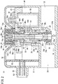
FIG. 1 is a cross-sectional view of a flow rate adjusting valve according to an embodiment of the present invention, when a handle is in a lower limit position, and the valve opening degree is maximum (a fully open state); -
FIG. 2 is a cross-sectional view of the flow rate adjusting valve shown inFIG. 1 , when the handle is in the lower limit position, and the valve opening degree is zero (a fully closed state); -
FIG. 3 is a view in which the flow rate adjusting valve shown inFIG. 1 is expanded into parts or groups of parts; -
FIG. 4 is a cross-sectional view of principal components of the flow rate adjusting valve shown inFIG. 1 , when the handle is in an upper limit position; -
FIG. 5 is a cross-sectional view of principal components of the flow rate adjusting valve shown inFIG. 1 , in a state during which the handle is being pushed down from the upper limit position to the lower limit position; and -
FIG. 6 is a cross-sectional view of principal components of the flow rate adjusting valve shown inFIG. 1 , in a state during which the handle is being pulled upward from the lower limit position to the upper limit position. - A flow
rate adjusting valve 10 according to an embodiment of the present invention is used to adjust the flow rate of a fluid such as compressed air or the like. In the following description, when the terms in relation to the up, down, left, and right directions are used, for the sake of convenience, such terms refer to the directions shown in the drawings, however, the actual arrangement of the respective component members is not necessarily limited to this feature. - As shown in
FIGS. 1 and3 , the flowrate adjusting valve 10 includes amain body 12, acover 14, avalve seat body 28, aneedle valve 34, ahandle 56, a stepping motor (electric motor) 58, and a motive power transmission mechanism. The motive power transmission mechanism is a mechanism that selectively switches between a rotational operating force of thehandle 56 and a driving force of thestepping motor 58, and transmits the selected force to theneedle valve 34. Details of the motive power transmission mechanism will be described later. Thestepping motor 58 has a non-illustrated speed reducing gear incorporated therein. According to the present embodiment, thestepping motor 58 is used as the electric motor, but other types of electric motors may also be used. - The box-shaped
main body 12 includes anaccommodating chamber 40 in which thestepping motor 58 and the motive power transmission mechanism are accommodated in cooperation with thecover 14. Thecover 14 is attached to asupport frame 60, which will be described later. An upper surface of thecover 14 is recessed downward at a position in proximity to a central location thereof in the longitudinal direction. The center of a bottomed surface of arecess 14a is open. A tubularhandle supporting member 16 that rises upwardly from an open edge of therecess 14a is provided integrally with thecover 14. - A lower part of the
main body 12 includes afluid passage 18 both ends of which are open, and which extends in a left and right direction. Afirst port 20 that opens on one end of thefluid passage 18, and asecond port 22 that opens on another end of thefluid passage 18 are respectively connected to non-illustrated external pipes. According to the present embodiment, a configuration is provided so that, by action of a later-describedcheck valve 30, the flow rate can be adjusted when the fluid flows from thefirst port 20 toward thesecond port 22. - The
valve seat body 28 and theneedle valve 34 are arranged in a manner so as to intersect thefluid passage 18. A cylindricalshaped guide wall 24 for guiding the fluid is arranged at a central location of thefluid passage 18 in the longitudinal direction. A central axis of theguide wall 24 is aligned with a central axis of thevalve seat body 28 and theneedle valve 34. Theguide wall 24 includes afirst window portion 24a, which is formed at an upper location of a portion of the guide wall that is closer to thefirst port 20. Theguide wall 24 includes asecond window portion 24b, which is formed at a lower location of a portion of the guide wall that is closer to thesecond port 22. Thefirst port 20 is connected to thesecond port 22 via thefirst window portion 24a and thesecond window portion 24b. Theguide wall 24 extends into theaccommodating chamber 40, and the extended portion thereof constitutes a supportingwall 26 that supports thevalve seat body 28. - The tubular
valve seat body 28 includes a supportingportion 28a, which is positioned at a central location of the valve seat body in the longitudinal direction. The supportingportion 28a is fitted and fixed to an inner side of the supportingwall 26 of themain body 12. On the inner side of thevalve seat body 28, theneedle valve 34 is inserted and arranged so as to be capable of moving in the X direction, which is the axial direction thereof. A distal end of theneedle valve 34 faces toward thefluid passage 18. The outer circumference of a portion of theneedle valve 34 that is in proximity to a distal end of the needle valve has atapered surface 34a. - A more downward location than the supporting
portion 28a of thevalve seat body 28 includes a plurality oflateral holes 28b that penetrate through the side wall of thevalve seat body 28. Thevalve seat body 28 further includes avalve seat 28c at a more downward location than thelateral holes 28b. The valve seat is capable of abutting against thetapered surface 34a of theneedle valve 34. In a state in which theneedle valve 34 is separated away from thevalve seat 28c, thefirst window portion 24a communicates with thesecond window portion 24b via the lateral holes 28b of thevalve seat body 28 and alower end opening 28e of thevalve seat body 28. As shown inFIG. 2 , in a state in which theneedle valve 34 is placed in abutment against thevalve seat 28c, communication between thefirst window portion 24a and thesecond window portion 24b via the lateral holes 28b of thevalve seat body 28 and thelower end opening 28e of thevalve seat body 28 is blocked. - A
check valve 30, which can be placed in pressure-contact with an inner circumference of theguide wall 24 of themain body 12, is mounted on the outer circumference of a lower end part of thevalve seat body 28. Thecheck valve 30 prevents the fluid from flowing from thefirst window portion 24a to thesecond window portion 24b through a gap between the lower end part of thevalve seat body 28 and theguide wall 24. Thecheck valve 30 allows the fluid to flow through the aforementioned gap from thesecond window portion 24b to thefirst window portion 24a. In a state in which theneedle valve 34 is placed in abutment against thevalve seat 28c, flowing of the fluid from thefirst port 20 to thesecond port 22 is prevented. In a state in which theneedle valve 34 is separated away from thevalve seat 28c, the fluid flows from thefirst port 20 toward thesecond port 22 at a flow rate corresponding to a flow path area which changes in accordance with the separation distance thereof. - A
cylindrical collar 38 that supports an upper end part of theneedle valve 34 is fixed to an inner surface of thevalve seat body 28 at a more upward location than the supportingportion 28a. An outer circumference of theneedle valve 34 and an inner circumference of thecollar 38 are equipped with two sets offlat surfaces needle valve 34 is supported by thecollar 38, in a manner so that rotation about a central axis is restricted, together with theneedle valve 34 being capable of moving in the axial direction. According to the embodiment, the two sets of flat surfaces are used as a means for preventing theneedle valve 34 from rotating with respect to thecollar 38. However, a means such as a set of flat surface portions (D-cuts), splines, or the like may also be used. - An
annular seal member 32, which abuts against an inner circumference of the supportingwall 26 of themain body 12, is mounted on an outer circumference of the supportingportion 28a of thevalve seat body 28. Further, an annular needle packing 36, which is placed in sliding contact with an inner circumference of the supportingportion 28a of thevalve seat body 28, is mounted on the outer circumference of theneedle valve 34. Thefluid passage 18 is separated in an airtight manner from theaccommodating chamber 40 by theseal member 32 and the needle packing 36. Since theneedle valve 34 is formed with a structure in which rotation about the central axis does not take place, the load applied to the needle packing 36 is reduced, and the durability of the needle packing 36 is enhanced. - The motive power transmission mechanism includes a
feed screw 42, astem 44, ahandle holder 46, avalve gear 48, and amotor gear 50. The rotational operating force of thehandle 56 is transmitted to theneedle valve 34 via thehandle holder 46, thestem 44, and thefeed screw 42. The driving force of the steppingmotor 58 is transmitted to theneedle valve 34 via themotor gear 50, thevalve gear 48, thestem 44, and thefeed screw 42. Stated otherwise, the motive power transmission path between thehandle 56 and theneedle valve 34 is constituted by thehandle holder 46, thestem 44, and thefeed screw 42. The motive power transmission path between the steppingmotor 58 and theneedle valve 34 is constituted by themotor gear 50, thevalve gear 48, thestem 44, and thefeed screw 42. Hereinafter, a description will be given in detail of the motive power transmission mechanism. - The
feed screw 42 includes aflange 42a in a central location thereof in the longitudinal direction, and further includes amale screw 42b on an outer circumference at a more downward location than theflange 42a. Thefeed screw 42 is rotatably supported by abearing 52 provided on an upper end opening 28d of thevalve seat body 28, at a more upward location than theflange 42a. An upper end of thefeed screw 42 projects upwardly from thebearing 52, and is fitted on an inner side of a later-describedcylindrical portion 44b of thestem 44. - The
needle valve 34 includes a bottomedscrew hole 34b that opens at the upper end of theneedle valve 34. A lower portion of thefeed screw 42 is screwed-engaged with thescrew hole 34b. Theflange 42a of thefeed screw 42 is arranged in a manner of being sandwiched between a lower surface of thebearing 52 and an upper surface of thecollar 38. Consequently, movement of thefeed screw 42 in the X direction, which is the axial direction, is restricted. When thefeed screw 42 is rotated, theneedle valve 34, the rotation of which about the central axis is restricted, moves in the axial direction. - The
stem 44 includes a plate-shapedflange portion 44a that extends in a horizontal direction, acylindrical portion 44b extending downward from theflange portion 44a and the distal end of which is open, and a protrudingportion 44c that protrudes upwardly from theflange portion 44a. Thecylindrical portion 44b of thestem 44 is connected to the upper end part of thefeed screw 42 by a predetermined means for preventing rotation. Consequently, thefeed screw 42 rotates integrally with thestem 44, and thestem 44 is capable of moving relative to thefeed screw 42 in the X direction, which is the axial direction. According to the present embodiment, two sets of flat surface portions are used as the means for preventing rotation, but one set of flat surface portions (D-cuts), splines, or the like may also be used. - Upward movement of the
stem 44 is restricted by theflange portion 44a of thestem 44 coming into abutment against astep portion 16a, which is disposed in a projecting manner from an inner circumference of thehandle supporting member 16 of thecover 14. An outer circumference of the upper end part of thecylindrical portion 44b of thestem 44 is equipped withsplines 44d that engage with later-describedsplines 48d of the valve gear 48 (seeFIG. 4 ). Thehandle holder 46 is fixed by a mountingscrew 54 to the protrudingportion 44c of thestem 44. An outer circumference of thehandle holder 46 includessplines 46a that engage with later-describedfirst splines 56f of the handle 56 (seeFIG. 5 ). - The
handle 56 includes anannular seat portion 56a, an outertubular portion 56b extending downward from an outer circumferential part of theseat portion 56a, and an innertubular portion 56c extending downward from an inner circumferential part of theseat portion 56a. A lower end of the outertubular portion 56b is equipped with arib 56d that projects inwardly in the radial direction. A lower end of the innertubular portion 56c is equipped with aflange 56e that extends inwardly in the radial direction. As shown inFIG. 4 , an inner circumference of the innertubular portion 56c in proximity to the lower end is provided withfirst splines 56f that engage with thesplines 46a of thehandle holder 46. Further, an outer circumference of the innertubular portion 56c in proximity to the upper end is provided withsecond splines 56g that engage withsplines 16d provided on the inner circumference of thehandle supporting member 16 of thecover 14. - The
handle 56 is capable of being subjected to a push-pull operation, and is capable of moving in the X direction (upper and lower direction), which is the direction of the axis of rotation thereof, between the upper limit position (upward end of movement) and the lower limit position (downward end of movement) as will be discussed below. When the upper surface of theflange 56e of thehandle 56 abuts against the lower surface of thehandle holder 46 and thehandle holder 46 is pulled upward, theflange portion 44a of thestem 44 which moves integrally with thehandle holder 46 abuts against thestep portion 16a of thehandle supporting member 16. As a result, thehandle 56 arrives at the upper limit position (seeFIG. 4 ). - The
handle supporting member 16 enters into a space between the innertubular portion 56c and the outertubular portion 56b of thehandle 56. When a lower surface of theseat portion 56a of thehandle 56 abuts against an upper end of thehandle supporting member 16, thehandle 56 arrives at the lower limit position (seeFIG. 1 ). When thehandle 56 is at the upper limit position, thehandle 56 protrudes significantly upward from thecover 14, whereby the rotational operation becomes easy to perform. When thehandle 56 is at the lower limit position, thehandle 56 enters into therecess 14a of thecover 14. - When the
handle 56 is moved upward (in a first direction), thefirst splines 56f of the innertubular portion 56c engage with thesplines 46a of thehandle holder 46. As a result, thehandle 56, thehandle holder 46, and thestem 44 can be rotated together in an integral manner. Further, when thehandle 56 is moved to the upper limit position, engagement between thesecond splines 56g of the innertubular portion 56c and thesplines 16d of thehandle supporting member 16 is released. - When the
handle 56 is moved downward (in a second direction), engagement between thefirst splines 56f of the innertubular portion 56c and thesplines 46a of thehandle holder 46 that is integral with thestem 44 is released. When thehandle 56 is moved downward, thesecond splines 56g of the innertubular portion 56c engage with thesplines 16d of thehandle supporting member 16, and rotation of thehandle 56 is prevented. Further, when thesecond splines 56g of the innertubular portion 56c start to engage with thesplines 16d of thehandle supporting member 16, theflange 56e of the innertubular portion 56c comes into abutment against theflange portion 44a of thestem 44. Due to theflange 56e pushing theflange portion 44a downward, thestem 44 moves downward together with thehandle 56. - The outer circumference of the
handle supporting member 16 of thecover 14 is equipped with afirst rib 16b and asecond rib 16c that are arranged at a predetermined interval in the vertical direction. Thefirst rib 16b and thesecond rib 16c engage with therib 56d of the outertubular portion 56b of thehandle 56. When thehandle 56 is pulled up to the upper limit position, therib 56d of thehandle 56 snap-engages with thefirst rib 16b of thehandle supporting member 16. When thehandle 56 is pushed down to the lower limit position, therib 56d of thehandle 56 snap-engages with thesecond rib 16c of thehandle supporting member 16. Accordingly, unless an external force is applied thereto, thehandle 56 that has reached the upper limit position or the lower limit position is stably retained at the upper limit position or the lower limit position. - In the
accommodating chamber 40, thesupport frame 60 which serves to support the steppingmotor 58 is arranged in the horizontal direction. Thesupport frame 60 is attached to themain body 12 by a non-illustrated fixing means. Thevalve gear 48 enmeshes with themotor gear 50 that is attached to anoutput shaft 58a of the steppingmotor 58, and rotates in conjunction with theoutput shaft 58a of the steppingmotor 58. Thevalve gear 48 and themotor gear 50 are arranged on an upper surface of thesupport frame 60. Thevalve gear 48 is made up from agear portion 48a having teeth on the outer circumference thereof, and ashaft portion 48b that protrudes downward from thegear portion 48a. Thegear portion 48a and theshaft portion 48b include acentral hole 48c that penetrates in the X direction, which is the axial direction thereof. An inner circumference of thegear portion 48a is equipped with thesplines 48d that engage with thesplines 44d of the stem 44 (seeFIG. 4 ). - The
support frame 60 includes aninsertion hole 60a into which thefeed screw 42 and thestem 44 are inserted. An upper part of theinsertion hole 60a is formed with an enlarged diameter that serves as afirst recess 60b for supporting theshaft portion 48b of thevalve gear 48. A lower part of theinsertion hole 60a has a diameter that is enlarged stepwise, and forms asecond recess 60c into which the upper end part of thevalve seat body 28 is inserted. Theshaft portion 48b of thevalve gear 48 is inserted into thefirst recess 60b. Aconvex portion 48e provided on an upper surface of thegear portion 48a abuts against thecover 14. Due to this feature, thevalve gear 48 is supported so as to be capable of rotating about the central axis, while movement thereof in the X direction, which is the axial direction, is restricted. Thesupport frame 60 is positioned in the interior of theaccommodating chamber 40 by fitting the upper end part of thevalve seat body 28 into thesecond recess 60c of thesupport frame 60. - The
cylindrical portion 44b of thestem 44 is inserted into thecentral hole 48c of thevalve gear 48 and theinsertion hole 60a of thesupport frame 60. When thestem 44 is moved downward by pushing down on thehandle 56, thesplines 44d of thestem 44 engage with thesplines 48d of thevalve gear 48. Consequently, the driving force of the steppingmotor 58 is transmitted to thefeed screw 42 via themotor gear 50, thevalve gear 48, and thestem 44. On the other hand, when thestem 44 is moved upward by pulling thehandle 56 upward, engagement between thesplines 44d of thestem 44 and thesplines 48d of thevalve gear 48 is released. - A
circuit board 62, which is perpendicular with respect to thesupport frame 60, is disposed in theaccommodating chamber 40. Electronic components in order to drive the steppingmotor 58 are mounted on thecircuit board 62. Needle-shapedterminals 64 that are erected on thecircuit board 62 extend to the inner side of atubular connector portion 66 provided on a side surface of themain body 12. Non-illustrated wirings are provided between thecircuit board 62 and the steppingmotor 58. The steppingmotor 58 is driven by a remote control signal supplied from theterminals 64. - The flow
rate adjusting valve 10 according to the present embodiment is configured in the manner described above. Hereinafter, descriptions will be given concerning a case in which the valve opening degree is adjusted by remote control, and a case in which the valve opening degree is manually adjusted. As shown inFIG. 4 , the state in which thehandle 56 is in the upper limit position is regarded as an initial state. - For driving the stepping
motor 58 by remote control to thereby adjust the valve opening degree, thehandle 56, which is at the upper limit position, is pushed down to the lower limit position. As shown inFIG. 5 , when thehandle 56 is pushed downward, initially, the engagement between thefirst splines 56f of the innertubular portion 56c of thehandle 56 and thesplines 46a of thehandle holder 46 is released, and thestem 44, which is integral with thehandle holder 46, is released from the connected state with thehandle 56. More specifically, the motive power transmission path between thehandle 56 and theneedle valve 34 is interrupted midway, i.e., interrupted between thehandle 56 and thehandle holder 46. Moreover, an appropriate frictional force is applied at a location where the upper end part of thefeed screw 42 is fitted into thecylindrical portion 44b of thestem 44, or alternatively, at a location where thecylindrical portion 44b of thestem 44 is inserted through thecentral hole 48c of thevalve gear 48. Therefore, when thehandle 56 is pushed down, thestem 44 does not move downward immediately. - Further, substantially at the same time that the engagement between the
first splines 56f of thehandle 56 and thesplines 46a of thehandle holder 46 is released, thesecond splines 56g of the innertubular portion 56c of thehandle 56 start to engage with thesplines 16d of thehandle supporting member 16, and a state is brought about in which rotation of thehandle 56 is prevented. - In addition, when the
handle 56 is pushed down in close proximity to the lower limit position, thestem 44 is pushed down by theflange 56e of thehandle 56, and thesplines 44d of thestem 44 engage with thesplines 48d of the valve gear 48 (seeFIG. 1 ). Consequently, a state is brought about in which the driving force of the steppingmotor 58 is capable of being transmitted to theneedle valve 34 via themotor gear 50, thevalve gear 48, thestem 44, and thefeed screw 42. More specifically, the motive power transmission path between the steppingmotor 58 and theneedle valve 34 becomes continuous. - As noted previously, when the
handle 56 is pushed down, a state is brought about in which the motive power transmission path between thehandle 56 and theneedle valve 34 is interrupted midway and rotation of thehandle 56 is prevented. If thehandle 56 is further pushed down to the lower limit position, the motive power transmission path between the steppingmotor 58 and theneedle valve 34 becomes continuous. In such a state, the steppingmotor 58 can be driven by remote control, thereby causing theneedle valve 34 to be moved in the axial direction, and enabling the valve opening degree to be adjusted. - Next, in order to manually adjust the valve opening degree, the
handle 56 which is at the lower limit position is pulled upward to the upper limit position. As shown inFIG. 6 , when thehandle 56 is pulled upward, initially, thefirst splines 56f of the innertubular portion 56c engage with thesplines 46a of thehandle holder 46, and the three constituent elements, i.e., thehandle 56, thehandle holder 46, and thestem 44, are integrally connected in the direction of rotation. Owing to this feature, the motive power transmission path between thehandle 56 and theneedle valve 34 becomes continuous. Incidentally, the engagement between thesecond splines 56g of the innertubular portion 56c and thesplines 16d of thehandle supporting member 16 cannot be released unless thehandle 56 is pulled upward to a portion in close proximity to the upper limit position. Therefore, at this point in time, thehandle 56 cannot be rotated. - Subsequently, when the
handle 56 is pulled upward to a position in close proximity to the upper limit position, thehandle holder 46 is pushed up by theflange 56e of thehandle 56. Consequently, the engagement between thesplines 44d of thestem 44, which moves integrally with thehandle holder 46, and thesplines 48d of thevalve gear 48 is released (seeFIG. 4 ). Further, the engagement between thesecond splines 56g of the innertubular portion 56c of thehandle 56 and thesplines 16d of thehandle supporting member 16 is released. By the engagement between thesplines 44d of thestem 44 and thesplines 48d of thevalve gear 48 being released, the motive power transmission path between the steppingmotor 58 and theneedle valve 34 is interrupted midway. - Accordingly, if the
handle 56 is pulled upward to the upper limit position, a situation is brought about in which thehandle 56 can be manually rotated. Therefore, by rotating thehandle 56, theneedle valve 34 can be moved in the axial direction via thehandle holder 46, thestem 44, and thefeed screw 42, and the valve opening degree can be adjusted. - A case is assumed in which, while an on-site worker is pulling the
handle 56 upward, prior to the engagement between thesplines 48d of thevalve gear 48 and thesplines 44d of thestem 44 being released, the steppingmotor 58 is driven by a remote control signal, and such a driving force is transmitted to thehandle 56 by way of thestem 44. Even in such a case, thesecond splines 56g of the innertubular portion 56c of thehandle 56 are engaged with thesplines 16d of thehandle supporting member 16. Therefore, thehandle 56 does not rotate unexpectedly, and the safety of an operator who is gripping thehandle 56 is assured. - In accordance with the flow
rate adjusting valve 10 according to the present invention, there is provided the motive power transmission mechanism that selectively switches between the rotational operating force of thehandle 56 and the driving force of the steppingmotor 58, and transmits the selected force to theneedle valve 34. Therefore, regardless of the specifications of the steppingmotor 58, manual operation of the handle can be easily realized, and the safety of on-site workers is assured. Further, since the aforementioned switching can be performed by a push-pull operation of causing thehandle 56 to be moved in the direction of the axis of rotation, ease of operation is satisfactory.
Claims (10)
- A flow rate adjusting valve (10) in which a needle valve (34) is arranged so as to face a fluid passage (18) of a main body (12), the flow rate adjusting valve comprising:a handle (56) configured to enable a rotational operation to be performed manually;an electric motor (58) configured to be operated remotely; anda motive power transmission mechanism configured to selectively switch between a rotational operating force of the handle and a driving force of the electric motor, and to transmit the force to the needle valve,wherein the switching is performed by causing the handle to be moved in a direction of an axis of rotation.
- The flow rate adjusting valve according to claim 1, wherein:the handle is configured to be moved along the axis of rotation of the handle in first and second directions that are mutually opposite to each other;when the handle is pulled and moved in the first direction, a motive power transmission path between the handle and the needle valve is made continuous, and a motive power transmission path between the electric motor and the needle valve is interrupted midway; andwhen the handle is pushed and moved in the second direction, the motive power transmission path between the handle and the needle valve is interrupted midway, and the motive power transmission path between the electric motor and the needle valve is made continuous.
- The flow rate adjusting valve according to claim 2, wherein:each of the handle and a handle supporting member (16) of the main body comprises splines (16d, 56g), the splines of the handle and the splines of the handle supporting member being configured to be mutually engaged; andwhen the handle is moved in the second direction from an end of movement in the first direction, the splines of the handle engage with the splines of the handle supporting member, whereby rotation of the handle is prevented.
- The flow rate adjusting valve according to claim 2, further comprising a cover (14) configured to accommodate the electric motor and the motive power transmission mechanism in cooperation with the main body, wherein the cover includes a recess (14a) into which the handle enters when the handle is moved to an end of movement in the second direction.
- The flow rate adjusting valve according to claim 2, wherein:the motive power transmission mechanism includes a feed screw (42) configured to be screw-engaged with the needle valve;rotation of the needle valve about a central axis is restricted;movement of the feed screw in an axial direction is restricted; andwhen the screw is rotated, the needle valve moves in the axial direction.
- The flow rate adjusting valve according to claim 5, wherein:the motive power transmission mechanism includes a stem (44) configured to move in an axial direction of the feed screw;the feed screw rotates integrally with the stem; andthe rotational operating force of the handle and the driving force of the electric motor are transmitted to the needle valve via the stem and the feed screw.
- The flow rate adjusting valve according to claim 6, wherein:when the handle moves in the first direction from an end of movement in the second direction, splines (56f) provided on the handle engage with splines (46a) provided on a handle holder (46) fixed to the stem; andwhen the handle moves in the second direction, the stem moves in a same direction, and splines (44d) provided on the stem engage with splines (48d) provided on a valve gear (48) configured to operate in conjunction with an output shaft (58a) of the electric motor.
- The flow rate adjusting valve according to claim 7, wherein:when the stem, which is integrated with the handle holder configured to be moved by abutment against the handle, abuts against a step portion (16a) provided on a handle supporting member, the handle reaches an end of movement in the first direction; andwhen the handle abuts against an end part of the handle supporting member, the handle reaches the end of movement in the second direction.
- The flow rate adjusting valve according to claim 8, wherein:when the handle reaches the end of movement in the first direction, a rib (56d) provided on the handle snap-engages with a first rib (16b) provided on the handle supporting member; andwhen the handle reaches the end of movement in the second direction, the rib provided on the handle snap-engages with a second rib (16c) provided on the handle supporting member.
- The flow rate adjusting valve according to claim 5, wherein:the needle valve is inserted and arranged inside a valve seat body (28) fixed to the main body; anda needle packing (36) in sliding contact with the valve seat body is mounted on an outer circumference of the needle valve.
Applications Claiming Priority (1)
| Application Number | Priority Date | Filing Date | Title |
|---|---|---|---|
| JP2020189945A JP7673385B6 (en) | 2020-11-16 | 2020-11-16 | Flow Control Valve |
Publications (2)
| Publication Number | Publication Date |
|---|---|
| EP4001710A1 true EP4001710A1 (en) | 2022-05-25 |
| EP4001710B1 EP4001710B1 (en) | 2024-07-31 |
Family
ID=78592579
Family Applications (1)
| Application Number | Title | Priority Date | Filing Date |
|---|---|---|---|
| EP21207072.6A Active EP4001710B1 (en) | 2020-11-16 | 2021-11-09 | Flow rate adjusting valve |
Country Status (6)
| Country | Link |
|---|---|
| US (1) | US11506301B2 (en) |
| EP (1) | EP4001710B1 (en) |
| JP (1) | JP7673385B6 (en) |
| KR (1) | KR20220066852A (en) |
| CN (1) | CN114508604B (en) |
| TW (1) | TWI884332B (en) |
Families Citing this family (3)
| Publication number | Priority date | Publication date | Assignee | Title |
|---|---|---|---|---|
| CN117146036B (en) * | 2022-05-23 | 2026-01-20 | 宁波英科特流体控制技术有限公司 | Manual diaphragm valve adjusting mechanism and electric diaphragm valve |
| JP2023174215A (en) * | 2022-05-27 | 2023-12-07 | 株式会社フジキン | valve |
| JP2024032284A (en) * | 2022-08-29 | 2024-03-12 | 愛三工業株式会社 | valve device |
Citations (4)
| Publication number | Priority date | Publication date | Assignee | Title |
|---|---|---|---|---|
| US2327980A (en) * | 1941-12-22 | 1943-08-31 | Crane Co | Automatic declutching means |
| US3845788A (en) * | 1973-10-03 | 1974-11-05 | Western States Machine Co | Motor controlled valve for continuously feeding viscous liquids |
| US4493336A (en) * | 1980-09-26 | 1985-01-15 | Renfro Wesley E | Hydraulic choking device |
| JP5061258B2 (en) | 2009-09-30 | 2012-10-31 | 株式会社コガネイ | Electric needle valve |
Family Cites Families (18)
| Publication number | Priority date | Publication date | Assignee | Title |
|---|---|---|---|---|
| US3309942A (en) * | 1965-05-27 | 1967-03-21 | King Of Prussia Res And Dev Co | Push-pull handwheel and motor drive |
| JPS5926134Y2 (en) * | 1977-01-29 | 1984-07-30 | 株式会社光合金製作所 | Valve drive device |
| US4092877A (en) * | 1977-03-14 | 1978-06-06 | Ledeen Flow Control Systems Inc. | Selective mode handwheel valve operator |
| JPS58121383A (en) * | 1982-01-12 | 1983-07-19 | Ube Ind Ltd | Flow regulating valve |
| US4647007A (en) * | 1986-02-24 | 1987-03-03 | Peter Bajka | Valve actuator with manual disengagement assembly |
| US4759386A (en) * | 1987-01-20 | 1988-07-26 | Pennwalt Corporation | Electromechanical linear actuator |
| JPH0187380U (en) * | 1987-12-01 | 1989-06-09 | ||
| JP2787402B2 (en) * | 1992-12-22 | 1998-08-20 | 株式会社 巴技術研究所 | Manual / electric switching device for valve actuator |
| US5547164A (en) * | 1994-12-28 | 1996-08-20 | Ratnik Industries, Inc. | Motorized water hydrant with manual override |
| WO2001069113A1 (en) * | 2000-03-14 | 2001-09-20 | Kitz Corporation | Electric actuator and fixing structure of the actuator |
| ITTO20050566A1 (en) * | 2005-08-08 | 2007-02-09 | Ferrero Rubinetterie S R L | DRIVING SYSTEM BOTH MANUAL AND AUTOMATIC FOR VALVES, FIXING JOINT FOR THIS SYSTEM AND SUPPLY KIT OF THIS SYSTEM OR OF THAT JUNCTION |
| JP2010223264A (en) * | 2009-03-19 | 2010-10-07 | Icomes Labo:Kk | Flow control valve |
| TWI520475B (en) * | 2010-04-07 | 2016-02-01 | 西部電機股份有限公司 | Actuator and method for detecting position using same |
| JP6189126B2 (en) * | 2012-08-31 | 2017-08-30 | 日立オートモティブシステムズメジャメント株式会社 | Pressure control device |
| JP6873391B2 (en) * | 2016-05-06 | 2021-05-19 | Toto株式会社 | Flow control valve and its manufacturing method |
| US11149871B2 (en) * | 2016-10-26 | 2021-10-19 | Fujikin Incorporated | Flow rate adjustment valve, and fluid control apparatus in which the flow rate adjustment valve is used |
| CN108561605A (en) * | 2018-07-17 | 2018-09-21 | 常州诚磊阀门科技有限公司 | A kind of valve actuating device and valve |
| CN109630738B (en) * | 2018-12-04 | 2021-04-30 | 北京精密机电控制设备研究所 | High-integration electric actuating mechanism for operating stop valve |
-
2020
- 2020-11-16 JP JP2020189945A patent/JP7673385B6/en active Active
-
2021
- 2021-10-25 US US17/452,088 patent/US11506301B2/en active Active
- 2021-11-04 TW TW110141156A patent/TWI884332B/en active
- 2021-11-09 EP EP21207072.6A patent/EP4001710B1/en active Active
- 2021-11-15 KR KR1020210156858A patent/KR20220066852A/en active Pending
- 2021-11-15 CN CN202111346387.2A patent/CN114508604B/en active Active
Patent Citations (4)
| Publication number | Priority date | Publication date | Assignee | Title |
|---|---|---|---|---|
| US2327980A (en) * | 1941-12-22 | 1943-08-31 | Crane Co | Automatic declutching means |
| US3845788A (en) * | 1973-10-03 | 1974-11-05 | Western States Machine Co | Motor controlled valve for continuously feeding viscous liquids |
| US4493336A (en) * | 1980-09-26 | 1985-01-15 | Renfro Wesley E | Hydraulic choking device |
| JP5061258B2 (en) | 2009-09-30 | 2012-10-31 | 株式会社コガネイ | Electric needle valve |
Also Published As
| Publication number | Publication date |
|---|---|
| JP7673385B6 (en) | 2025-06-06 |
| US20220154840A1 (en) | 2022-05-19 |
| KR20220066852A (en) | 2022-05-24 |
| CN114508604B (en) | 2026-04-28 |
| US11506301B2 (en) | 2022-11-22 |
| JP2022079024A (en) | 2022-05-26 |
| EP4001710B1 (en) | 2024-07-31 |
| TWI884332B (en) | 2025-05-21 |
| JP7673385B2 (en) | 2025-05-09 |
| TW202225588A (en) | 2022-07-01 |
| CN114508604A (en) | 2022-05-17 |
Similar Documents
| Publication | Publication Date | Title |
|---|---|---|
| EP4001710B1 (en) | Flow rate adjusting valve | |
| US8967590B2 (en) | Micro-power generator for valve control applications | |
| US11135729B2 (en) | Method and system for automatically changing shafts | |
| US10648541B2 (en) | Rotary actuator | |
| US11408531B2 (en) | Spool valve | |
| EP0068769B1 (en) | A robot wrist of an industrial robot | |
| WO2016204158A1 (en) | Valve seat machining device, and valve seat machining method using said valve seat machining device | |
| CN105333201B (en) | Manually, motor-driven double drive valve | |
| EP3805622A1 (en) | Electric actuator | |
| JP4600307B2 (en) | Automatic machine system | |
| EP1777028A1 (en) | Control device | |
| KR101919136B1 (en) | Hydraulic actuator for power plant and maintenance method thereof | |
| NO20200975A1 (en) | Multi valve electrical actuator | |
| CN115087828A (en) | Valve actuator | |
| CN115013585A (en) | Remote operation cuts cock and rail vehicle | |
| JP2005161486A (en) | Robot system | |
| KR101860437B1 (en) | Assembly apparatus for firefighting pipe | |
| WO2005068774A1 (en) | Control system of an actuator for the actuation of submarine devices | |
| US20240219878A1 (en) | Valve Control Device | |
| KR100812560B1 (en) | Flow control valve | |
| JPWO2007135721A1 (en) | Valve drive device | |
| US20210062920A1 (en) | System and method for valve conversion | |
| KR102759607B1 (en) | Integrated shut-off apparatus for emergency shut-off actuators for pressure vessels | |
| CN107263132B (en) | Rotary transmission control device | |
| CN215881695U (en) | Mounting tool assembly for wrist shaft and mechanical arm of robot |
Legal Events
| Date | Code | Title | Description |
|---|---|---|---|
| PUAI | Public reference made under article 153(3) epc to a published international application that has entered the european phase |
Free format text: ORIGINAL CODE: 0009012 |
|
| STAA | Information on the status of an ep patent application or granted ep patent |
Free format text: STATUS: THE APPLICATION HAS BEEN PUBLISHED |
|
| AK | Designated contracting states |
Kind code of ref document: A1 Designated state(s): AL AT BE BG CH CY CZ DE DK EE ES FI FR GB GR HR HU IE IS IT LI LT LU LV MC MK MT NL NO PL PT RO RS SE SI SK SM TR |
|
| STAA | Information on the status of an ep patent application or granted ep patent |
Free format text: STATUS: REQUEST FOR EXAMINATION WAS MADE |
|
| 17P | Request for examination filed |
Effective date: 20221118 |
|
| RBV | Designated contracting states (corrected) |
Designated state(s): AL AT BE BG CH CY CZ DE DK EE ES FI FR GB GR HR HU IE IS IT LI LT LU LV MC MK MT NL NO PL PT RO RS SE SI SK SM TR |
|
| GRAP | Despatch of communication of intention to grant a patent |
Free format text: ORIGINAL CODE: EPIDOSNIGR1 |
|
| STAA | Information on the status of an ep patent application or granted ep patent |
Free format text: STATUS: GRANT OF PATENT IS INTENDED |
|
| INTG | Intention to grant announced |
Effective date: 20240328 |
|
| GRAS | Grant fee paid |
Free format text: ORIGINAL CODE: EPIDOSNIGR3 |
|
| GRAA | (expected) grant |
Free format text: ORIGINAL CODE: 0009210 |
|
| STAA | Information on the status of an ep patent application or granted ep patent |
Free format text: STATUS: THE PATENT HAS BEEN GRANTED |
|
| AK | Designated contracting states |
Kind code of ref document: B1 Designated state(s): AL AT BE BG CH CY CZ DE DK EE ES FI FR GB GR HR HU IE IS IT LI LT LU LV MC MK MT NL NO PL PT RO RS SE SI SK SM TR |
|
| REG | Reference to a national code |
Ref country code: CH Ref legal event code: EP Ref country code: GB Ref legal event code: FG4D |
|
| REG | Reference to a national code |
Ref country code: DE Ref legal event code: R096 Ref document number: 602021016415 Country of ref document: DE |
|
| REG | Reference to a national code |
Ref country code: IE Ref legal event code: FG4D |
|
| REG | Reference to a national code |
Ref country code: LT Ref legal event code: MG9D |
|
| REG | Reference to a national code |
Ref country code: NL Ref legal event code: MP Effective date: 20240731 |
|
| PG25 | Lapsed in a contracting state [announced via postgrant information from national office to epo] |
Ref country code: PT Free format text: LAPSE BECAUSE OF FAILURE TO SUBMIT A TRANSLATION OF THE DESCRIPTION OR TO PAY THE FEE WITHIN THE PRESCRIBED TIME-LIMIT Effective date: 20241202 |
|
| REG | Reference to a national code |
Ref country code: AT Ref legal event code: MK05 Ref document number: 1708728 Country of ref document: AT Kind code of ref document: T Effective date: 20240731 |
|
| PG25 | Lapsed in a contracting state [announced via postgrant information from national office to epo] |
Ref country code: PT Free format text: LAPSE BECAUSE OF FAILURE TO SUBMIT A TRANSLATION OF THE DESCRIPTION OR TO PAY THE FEE WITHIN THE PRESCRIBED TIME-LIMIT Effective date: 20241202 |
|
| PG25 | Lapsed in a contracting state [announced via postgrant information from national office to epo] |
Ref country code: NO Free format text: LAPSE BECAUSE OF FAILURE TO SUBMIT A TRANSLATION OF THE DESCRIPTION OR TO PAY THE FEE WITHIN THE PRESCRIBED TIME-LIMIT Effective date: 20241031 |
|
| PG25 | Lapsed in a contracting state [announced via postgrant information from national office to epo] |
Ref country code: NL Free format text: LAPSE BECAUSE OF FAILURE TO SUBMIT A TRANSLATION OF THE DESCRIPTION OR TO PAY THE FEE WITHIN THE PRESCRIBED TIME-LIMIT Effective date: 20240731 Ref country code: GR Free format text: LAPSE BECAUSE OF FAILURE TO SUBMIT A TRANSLATION OF THE DESCRIPTION OR TO PAY THE FEE WITHIN THE PRESCRIBED TIME-LIMIT Effective date: 20241101 Ref country code: PL Free format text: LAPSE BECAUSE OF FAILURE TO SUBMIT A TRANSLATION OF THE DESCRIPTION OR TO PAY THE FEE WITHIN THE PRESCRIBED TIME-LIMIT Effective date: 20240731 Ref country code: FI Free format text: LAPSE BECAUSE OF FAILURE TO SUBMIT A TRANSLATION OF THE DESCRIPTION OR TO PAY THE FEE WITHIN THE PRESCRIBED TIME-LIMIT Effective date: 20240731 |
|
| PG25 | Lapsed in a contracting state [announced via postgrant information from national office to epo] |
Ref country code: BG Free format text: LAPSE BECAUSE OF FAILURE TO SUBMIT A TRANSLATION OF THE DESCRIPTION OR TO PAY THE FEE WITHIN THE PRESCRIBED TIME-LIMIT Effective date: 20240731 |
|
| PG25 | Lapsed in a contracting state [announced via postgrant information from national office to epo] |
Ref country code: LV Free format text: LAPSE BECAUSE OF FAILURE TO SUBMIT A TRANSLATION OF THE DESCRIPTION OR TO PAY THE FEE WITHIN THE PRESCRIBED TIME-LIMIT Effective date: 20240731 |
|
| PG25 | Lapsed in a contracting state [announced via postgrant information from national office to epo] |
Ref country code: IS Free format text: LAPSE BECAUSE OF FAILURE TO SUBMIT A TRANSLATION OF THE DESCRIPTION OR TO PAY THE FEE WITHIN THE PRESCRIBED TIME-LIMIT Effective date: 20241130 Ref country code: AT Free format text: LAPSE BECAUSE OF FAILURE TO SUBMIT A TRANSLATION OF THE DESCRIPTION OR TO PAY THE FEE WITHIN THE PRESCRIBED TIME-LIMIT Effective date: 20240731 |
|
| PG25 | Lapsed in a contracting state [announced via postgrant information from national office to epo] |
Ref country code: HR Free format text: LAPSE BECAUSE OF FAILURE TO SUBMIT A TRANSLATION OF THE DESCRIPTION OR TO PAY THE FEE WITHIN THE PRESCRIBED TIME-LIMIT Effective date: 20240731 |
|
| PG25 | Lapsed in a contracting state [announced via postgrant information from national office to epo] |
Ref country code: ES Free format text: LAPSE BECAUSE OF FAILURE TO SUBMIT A TRANSLATION OF THE DESCRIPTION OR TO PAY THE FEE WITHIN THE PRESCRIBED TIME-LIMIT Effective date: 20240731 Ref country code: RS Free format text: LAPSE BECAUSE OF FAILURE TO SUBMIT A TRANSLATION OF THE DESCRIPTION OR TO PAY THE FEE WITHIN THE PRESCRIBED TIME-LIMIT Effective date: 20241031 |
|
| PG25 | Lapsed in a contracting state [announced via postgrant information from national office to epo] |
Ref country code: RS Free format text: LAPSE BECAUSE OF FAILURE TO SUBMIT A TRANSLATION OF THE DESCRIPTION OR TO PAY THE FEE WITHIN THE PRESCRIBED TIME-LIMIT Effective date: 20241031 Ref country code: PL Free format text: LAPSE BECAUSE OF FAILURE TO SUBMIT A TRANSLATION OF THE DESCRIPTION OR TO PAY THE FEE WITHIN THE PRESCRIBED TIME-LIMIT Effective date: 20240731 Ref country code: NO Free format text: LAPSE BECAUSE OF FAILURE TO SUBMIT A TRANSLATION OF THE DESCRIPTION OR TO PAY THE FEE WITHIN THE PRESCRIBED TIME-LIMIT Effective date: 20241031 Ref country code: NL Free format text: LAPSE BECAUSE OF FAILURE TO SUBMIT A TRANSLATION OF THE DESCRIPTION OR TO PAY THE FEE WITHIN THE PRESCRIBED TIME-LIMIT Effective date: 20240731 Ref country code: LV Free format text: LAPSE BECAUSE OF FAILURE TO SUBMIT A TRANSLATION OF THE DESCRIPTION OR TO PAY THE FEE WITHIN THE PRESCRIBED TIME-LIMIT Effective date: 20240731 Ref country code: IS Free format text: LAPSE BECAUSE OF FAILURE TO SUBMIT A TRANSLATION OF THE DESCRIPTION OR TO PAY THE FEE WITHIN THE PRESCRIBED TIME-LIMIT Effective date: 20241130 Ref country code: HR Free format text: LAPSE BECAUSE OF FAILURE TO SUBMIT A TRANSLATION OF THE DESCRIPTION OR TO PAY THE FEE WITHIN THE PRESCRIBED TIME-LIMIT Effective date: 20240731 Ref country code: GR Free format text: LAPSE BECAUSE OF FAILURE TO SUBMIT A TRANSLATION OF THE DESCRIPTION OR TO PAY THE FEE WITHIN THE PRESCRIBED TIME-LIMIT Effective date: 20241101 Ref country code: FI Free format text: LAPSE BECAUSE OF FAILURE TO SUBMIT A TRANSLATION OF THE DESCRIPTION OR TO PAY THE FEE WITHIN THE PRESCRIBED TIME-LIMIT Effective date: 20240731 Ref country code: ES Free format text: LAPSE BECAUSE OF FAILURE TO SUBMIT A TRANSLATION OF THE DESCRIPTION OR TO PAY THE FEE WITHIN THE PRESCRIBED TIME-LIMIT Effective date: 20240731 Ref country code: BG Free format text: LAPSE BECAUSE OF FAILURE TO SUBMIT A TRANSLATION OF THE DESCRIPTION OR TO PAY THE FEE WITHIN THE PRESCRIBED TIME-LIMIT Effective date: 20240731 Ref country code: AT Free format text: LAPSE BECAUSE OF FAILURE TO SUBMIT A TRANSLATION OF THE DESCRIPTION OR TO PAY THE FEE WITHIN THE PRESCRIBED TIME-LIMIT Effective date: 20240731 |
|
| PG25 | Lapsed in a contracting state [announced via postgrant information from national office to epo] |
Ref country code: RO Free format text: LAPSE BECAUSE OF FAILURE TO SUBMIT A TRANSLATION OF THE DESCRIPTION OR TO PAY THE FEE WITHIN THE PRESCRIBED TIME-LIMIT Effective date: 20240731 Ref country code: SM Free format text: LAPSE BECAUSE OF FAILURE TO SUBMIT A TRANSLATION OF THE DESCRIPTION OR TO PAY THE FEE WITHIN THE PRESCRIBED TIME-LIMIT Effective date: 20240731 Ref country code: DK Free format text: LAPSE BECAUSE OF FAILURE TO SUBMIT A TRANSLATION OF THE DESCRIPTION OR TO PAY THE FEE WITHIN THE PRESCRIBED TIME-LIMIT Effective date: 20240731 |
|
| PG25 | Lapsed in a contracting state [announced via postgrant information from national office to epo] |
Ref country code: EE Free format text: LAPSE BECAUSE OF FAILURE TO SUBMIT A TRANSLATION OF THE DESCRIPTION OR TO PAY THE FEE WITHIN THE PRESCRIBED TIME-LIMIT Effective date: 20240731 |
|
| PG25 | Lapsed in a contracting state [announced via postgrant information from national office to epo] |
Ref country code: CZ Free format text: LAPSE BECAUSE OF FAILURE TO SUBMIT A TRANSLATION OF THE DESCRIPTION OR TO PAY THE FEE WITHIN THE PRESCRIBED TIME-LIMIT Effective date: 20240731 |
|
| PG25 | Lapsed in a contracting state [announced via postgrant information from national office to epo] |
Ref country code: SK Free format text: LAPSE BECAUSE OF FAILURE TO SUBMIT A TRANSLATION OF THE DESCRIPTION OR TO PAY THE FEE WITHIN THE PRESCRIBED TIME-LIMIT Effective date: 20240731 Ref country code: IT Free format text: LAPSE BECAUSE OF FAILURE TO SUBMIT A TRANSLATION OF THE DESCRIPTION OR TO PAY THE FEE WITHIN THE PRESCRIBED TIME-LIMIT Effective date: 20240731 |
|
| REG | Reference to a national code |
Ref country code: DE Ref legal event code: R097 Ref document number: 602021016415 Country of ref document: DE |
|
| PLBE | No opposition filed within time limit |
Free format text: ORIGINAL CODE: 0009261 |
|
| STAA | Information on the status of an ep patent application or granted ep patent |
Free format text: STATUS: NO OPPOSITION FILED WITHIN TIME LIMIT |
|
| RAP4 | Party data changed (patent owner data changed or rights of a patent transferred) |
Owner name: SMC CORPORATION |
|
| REG | Reference to a national code |
Ref country code: CH Ref legal event code: PL |
|
| PG25 | Lapsed in a contracting state [announced via postgrant information from national office to epo] |
Ref country code: MC Free format text: LAPSE BECAUSE OF FAILURE TO SUBMIT A TRANSLATION OF THE DESCRIPTION OR TO PAY THE FEE WITHIN THE PRESCRIBED TIME-LIMIT Effective date: 20240731 |
|
| 26N | No opposition filed |
Effective date: 20250501 |
|
| PG25 | Lapsed in a contracting state [announced via postgrant information from national office to epo] |
Ref country code: LU Free format text: LAPSE BECAUSE OF NON-PAYMENT OF DUE FEES Effective date: 20241109 |
|
| REG | Reference to a national code |
Ref country code: CH Ref legal event code: PL |
|
| PG25 | Lapsed in a contracting state [announced via postgrant information from national office to epo] |
Ref country code: CH Free format text: LAPSE BECAUSE OF NON-PAYMENT OF DUE FEES Effective date: 20241130 |
|
| REG | Reference to a national code |
Ref country code: BE Ref legal event code: MM Effective date: 20241130 |
|
| PG25 | Lapsed in a contracting state [announced via postgrant information from national office to epo] |
Ref country code: SE Free format text: LAPSE BECAUSE OF FAILURE TO SUBMIT A TRANSLATION OF THE DESCRIPTION OR TO PAY THE FEE WITHIN THE PRESCRIBED TIME-LIMIT Effective date: 20240731 |
|
| PG25 | Lapsed in a contracting state [announced via postgrant information from national office to epo] |
Ref country code: BE Free format text: LAPSE BECAUSE OF NON-PAYMENT OF DUE FEES Effective date: 20241130 |
|
| PG25 | Lapsed in a contracting state [announced via postgrant information from national office to epo] |
Ref country code: FR Free format text: LAPSE BECAUSE OF NON-PAYMENT OF DUE FEES Effective date: 20241130 |
|
| PG25 | Lapsed in a contracting state [announced via postgrant information from national office to epo] |
Ref country code: IE Free format text: LAPSE BECAUSE OF NON-PAYMENT OF DUE FEES Effective date: 20241109 |
|
| PGFP | Annual fee paid to national office [announced via postgrant information from national office to epo] |
Ref country code: DE Payment date: 20251119 Year of fee payment: 5 |
|
| PG25 | Lapsed in a contracting state [announced via postgrant information from national office to epo] |
Ref country code: HU Free format text: LAPSE BECAUSE OF FAILURE TO SUBMIT A TRANSLATION OF THE DESCRIPTION OR TO PAY THE FEE WITHIN THE PRESCRIBED TIME-LIMIT; INVALID AB INITIO Effective date: 20211109 |
|
| PG25 | Lapsed in a contracting state [announced via postgrant information from national office to epo] |
Ref country code: CY Free format text: LAPSE BECAUSE OF FAILURE TO SUBMIT A TRANSLATION OF THE DESCRIPTION OR TO PAY THE FEE WITHIN THE PRESCRIBED TIME-LIMIT; INVALID AB INITIO Effective date: 20211109 |