EP4001635A1 - Wind turbine, rotor hub for a wind turbine and related rotor assembly - Google Patents
Wind turbine, rotor hub for a wind turbine and related rotor assembly Download PDFInfo
- Publication number
- EP4001635A1 EP4001635A1 EP21208212.7A EP21208212A EP4001635A1 EP 4001635 A1 EP4001635 A1 EP 4001635A1 EP 21208212 A EP21208212 A EP 21208212A EP 4001635 A1 EP4001635 A1 EP 4001635A1
- Authority
- EP
- European Patent Office
- Prior art keywords
- rotor hub
- rotor
- flange sections
- wall
- hub
- Prior art date
- Legal status (The legal status is an assumption and is not a legal conclusion. Google has not performed a legal analysis and makes no representation as to the accuracy of the status listed.)
- Pending
Links
- 238000009434 installation Methods 0.000 claims description 3
- 238000005452 bending Methods 0.000 description 2
- 230000015572 biosynthetic process Effects 0.000 description 2
- 238000004519 manufacturing process Methods 0.000 description 2
- 230000008719 thickening Effects 0.000 description 2
- 230000004308 accommodation Effects 0.000 description 1
- 238000009960 carding Methods 0.000 description 1
- 238000010276 construction Methods 0.000 description 1
- 238000009826 distribution Methods 0.000 description 1
- 230000000694 effects Effects 0.000 description 1
- 238000005457 optimization Methods 0.000 description 1
- 230000002787 reinforcement Effects 0.000 description 1
- 238000005096 rolling process Methods 0.000 description 1
Images


Classifications
-
- F—MECHANICAL ENGINEERING; LIGHTING; HEATING; WEAPONS; BLASTING
- F03—MACHINES OR ENGINES FOR LIQUIDS; WIND, SPRING, OR WEIGHT MOTORS; PRODUCING MECHANICAL POWER OR A REACTIVE PROPULSIVE THRUST, NOT OTHERWISE PROVIDED FOR
- F03D—WIND MOTORS
- F03D1/00—Wind motors with rotation axis substantially parallel to the air flow entering the rotor
- F03D1/06—Rotors
- F03D1/065—Rotors characterised by their construction elements
- F03D1/0691—Rotors characterised by their construction elements of the hub
-
- F—MECHANICAL ENGINEERING; LIGHTING; HEATING; WEAPONS; BLASTING
- F03—MACHINES OR ENGINES FOR LIQUIDS; WIND, SPRING, OR WEIGHT MOTORS; PRODUCING MECHANICAL POWER OR A REACTIVE PROPULSIVE THRUST, NOT OTHERWISE PROVIDED FOR
- F03D—WIND MOTORS
- F03D1/00—Wind motors with rotation axis substantially parallel to the air flow entering the rotor
- F03D1/06—Rotors
- F03D1/0608—Rotors characterised by their aerodynamic shape
- F03D1/0633—Rotors characterised by their aerodynamic shape of the blades
-
- F—MECHANICAL ENGINEERING; LIGHTING; HEATING; WEAPONS; BLASTING
- F03—MACHINES OR ENGINES FOR LIQUIDS; WIND, SPRING, OR WEIGHT MOTORS; PRODUCING MECHANICAL POWER OR A REACTIVE PROPULSIVE THRUST, NOT OTHERWISE PROVIDED FOR
- F03D—WIND MOTORS
- F03D1/00—Wind motors with rotation axis substantially parallel to the air flow entering the rotor
- F03D1/06—Rotors
- F03D1/0608—Rotors characterised by their aerodynamic shape
-
- F—MECHANICAL ENGINEERING; LIGHTING; HEATING; WEAPONS; BLASTING
- F03—MACHINES OR ENGINES FOR LIQUIDS; WIND, SPRING, OR WEIGHT MOTORS; PRODUCING MECHANICAL POWER OR A REACTIVE PROPULSIVE THRUST, NOT OTHERWISE PROVIDED FOR
- F03D—WIND MOTORS
- F03D1/00—Wind motors with rotation axis substantially parallel to the air flow entering the rotor
- F03D1/06—Rotors
- F03D1/065—Rotors characterised by their construction elements
- F03D1/0675—Rotors characterised by their construction elements of the blades
-
- F—MECHANICAL ENGINEERING; LIGHTING; HEATING; WEAPONS; BLASTING
- F03—MACHINES OR ENGINES FOR LIQUIDS; WIND, SPRING, OR WEIGHT MOTORS; PRODUCING MECHANICAL POWER OR A REACTIVE PROPULSIVE THRUST, NOT OTHERWISE PROVIDED FOR
- F03D—WIND MOTORS
- F03D13/00—Assembly, mounting or commissioning of wind motors; Arrangements specially adapted for transporting wind motor components
- F03D13/10—Assembly of wind motors; Arrangements for erecting wind motors
-
- F—MECHANICAL ENGINEERING; LIGHTING; HEATING; WEAPONS; BLASTING
- F03—MACHINES OR ENGINES FOR LIQUIDS; WIND, SPRING, OR WEIGHT MOTORS; PRODUCING MECHANICAL POWER OR A REACTIVE PROPULSIVE THRUST, NOT OTHERWISE PROVIDED FOR
- F03D—WIND MOTORS
- F03D13/00—Assembly, mounting or commissioning of wind motors; Arrangements specially adapted for transporting wind motor components
- F03D13/20—Arrangements for mounting or supporting wind motors; Masts or towers for wind motors
-
- F—MECHANICAL ENGINEERING; LIGHTING; HEATING; WEAPONS; BLASTING
- F05—INDEXING SCHEMES RELATING TO ENGINES OR PUMPS IN VARIOUS SUBCLASSES OF CLASSES F01-F04
- F05B—INDEXING SCHEME RELATING TO WIND, SPRING, WEIGHT, INERTIA OR LIKE MOTORS, TO MACHINES OR ENGINES FOR LIQUIDS COVERED BY SUBCLASSES F03B, F03D AND F03G
- F05B2250/00—Geometry
- F05B2250/20—Geometry three-dimensional
- F05B2250/23—Geometry three-dimensional prismatic
- F05B2250/231—Geometry three-dimensional prismatic cylindrical
-
- F—MECHANICAL ENGINEERING; LIGHTING; HEATING; WEAPONS; BLASTING
- F05—INDEXING SCHEMES RELATING TO ENGINES OR PUMPS IN VARIOUS SUBCLASSES OF CLASSES F01-F04
- F05B—INDEXING SCHEME RELATING TO WIND, SPRING, WEIGHT, INERTIA OR LIKE MOTORS, TO MACHINES OR ENGINES FOR LIQUIDS COVERED BY SUBCLASSES F03B, F03D AND F03G
- F05B2260/00—Function
- F05B2260/30—Retaining components in desired mutual position
-
- F—MECHANICAL ENGINEERING; LIGHTING; HEATING; WEAPONS; BLASTING
- F16—ENGINEERING ELEMENTS AND UNITS; GENERAL MEASURES FOR PRODUCING AND MAINTAINING EFFECTIVE FUNCTIONING OF MACHINES OR INSTALLATIONS; THERMAL INSULATION IN GENERAL
- F16B—DEVICES FOR FASTENING OR SECURING CONSTRUCTIONAL ELEMENTS OR MACHINE PARTS TOGETHER, e.g. NAILS, BOLTS, CIRCLIPS, CLAMPS, CLIPS OR WEDGES; JOINTS OR JOINTING
- F16B2200/00—Constructional details of connections not covered for in other groups of this subclass
- F16B2200/50—Flanged connections
-
- Y—GENERAL TAGGING OF NEW TECHNOLOGICAL DEVELOPMENTS; GENERAL TAGGING OF CROSS-SECTIONAL TECHNOLOGIES SPANNING OVER SEVERAL SECTIONS OF THE IPC; TECHNICAL SUBJECTS COVERED BY FORMER USPC CROSS-REFERENCE ART COLLECTIONS [XRACs] AND DIGESTS
- Y02—TECHNOLOGIES OR APPLICATIONS FOR MITIGATION OR ADAPTATION AGAINST CLIMATE CHANGE
- Y02E—REDUCTION OF GREENHOUSE GAS [GHG] EMISSIONS, RELATED TO ENERGY GENERATION, TRANSMISSION OR DISTRIBUTION
- Y02E10/00—Energy generation through renewable energy sources
- Y02E10/70—Wind energy
- Y02E10/72—Wind turbines with rotation axis in wind direction
Definitions
- the bulkhead is, for example, cast on or attached to the rotor hub by means of screw connections.
- the advantages and preferred embodiments of the second aspect are at the same time advantages and preferred embodiments of the first aspect and vice versa, so that to avoid repetition, reference is also made to the above statements on the first aspect.
- the invention of both aspects is further developed in that the housing of the rotor hub has free-form wall areas adjacent to the flat wall areas. These free-form wall areas have also proven to be advantageous with regard to the optimization of the force and moment curves within the rotor hub.
Abstract
Die vorliegende Erfindung betrifft eine Rotornabe (114) für eine Windenergieanlage (100), mit wenigstens zwei Flanschabschnitten (116) zur Aufnahme jeweils eines Rotorblatts (108), wobei die Rotornabe (114) ein Gehäuse (118) mit einer Wandung (120) aufweist, welche durch die Flanschabschnitte (116) unterbrochen ist, wobei das Gehäuse (118) einen Wandbereich (122) zwischen zwei benachbarten Flanschabschnitten (116) aufweist. Die Erfindung betrifft ferner eine Rotoranordnung (106) für eine Windenergieanlage (100) und eine Windenergieanlage (100).Erfindungsgemäß wird vorgeschlagen, dass in dem Wandbereich (122) ein Flächenabschnitt (124) mit zylinderförmiger Krümmung (126) ausgebildet ist.The present invention relates to a rotor hub (114) for a wind turbine (100), with at least two flange sections (116) for receiving a rotor blade (108) each, the rotor hub (114) having a housing (118) with a wall (120). , which is interrupted by the flange sections (116), the housing (118) having a wall region (122) between two adjacent flange sections (116). The invention also relates to a rotor arrangement (106) for a wind turbine (100) and a wind turbine (100). According to the invention, a surface section (124) with a cylindrical curvature (126) is formed in the wall region (122).
Description
Die Erfindung betrifft eine Rotornabe für eine Windenergieanlage mit wenigstens zwei Flanschabschnitten zur Aufnahme jeweils eines Rotorblatts, wobei die Rotornabe ein Gehäuse mit einer Wandung aufweist, welche durch die Flanschabschnitte unterbrochen ist, wobei das Gehäuse einen Wandbereich zwischen zwei benachbarten Flanschabschnitten aufweist.The invention relates to a rotor hub for a wind turbine with at least two flange sections for accommodating one rotor blade each, the rotor hub having a housing with a wall which is interrupted by the flange sections, the housing having a wall area between two adjacent flange sections.
In der prioritätsbegründenden deutschen Anmeldung hat das Deutsche Patent- und Markenamt die folgenden Dokumente recherchiert:
Eine Rotornabe der eingangs genannten Art ist beispielsweise von Windenergieanlagen bekannt. Betreffende Windenergieanlagen weisen einen Turm, eine Gondel, einen Generator und eine mit dem Generator verbundene Rotornabe auf. Die Rotornabe ist mit mehreren Rotorblättern verbunden, wobei jeweils ein Rotorblatt mittels eines Blattlagers an einem Flanschabschnitt der Rotornabe angeordnet ist.A rotor hub of the type mentioned is known, for example, from wind turbines. Relevant wind turbines have a tower, a nacelle, a generator and a rotor hub connected to the generator. The rotor hub is connected to a plurality of rotor blades, one rotor blade each being arranged on a flange section of the rotor hub by means of a blade bearing.
Derartige Blattlager weisen einen Lageraußenring auf, der mittels einer Schraubverbindung mit dem Flanschabschnitt der Rotornabe verbunden ist, und einen Lagerinnenring, welcher mit dem betreffenden Rotorblatt verbunden ist. Darüber hinaus sind Blattlager bekannt, bei denen ein Lageraußenring mit einem betreffenden Rotorblatt verbunden ist und der Lagerinnenring mit der Rotornabe. Aus dem Stand der Technik vorbekannte Rotornaben weisen zumeist eine Kugelgeometrie auf, die durch die Flanschabschnitte unterbrochen ist.Such blade bearings have a bearing outer ring, which is connected to the flange section of the rotor hub by means of a screw connection, and a bearing inner ring, which is connected to the rotor blade in question. In addition, blade bearings are known in which a bearing outer ring is connected to a relevant rotor blade and the bearing inner ring is connected to the rotor hub. Rotor hubs known from the prior art usually have a spherical geometry that is interrupted by the flange sections.
Durch den Hebelarm zwischen den Schraubverbindungen des Lageraußenrings und der kugelförmigen Rotornabenoberfläche bzw. zwischen Lageraußenring und Lagerinnenring entstehen beim Betrieb der Windenergieanlage sogenannte Krempelmomente, welche ein Aufbiegen des Flanschabschnittes sowie umlaufende Ringspannungen im Lageraußenring des Blattlagers zur Folge haben. Zur Vermeidung von Ermüdungsrissen an den Bohrungen des Lageraußenrings ist aus dem Stand der Technik bekannt, die Wandstärken der Rotornabe und/oder eines sogenannten Schotts, welches im Inneren der Flanschabschnitte angeordnet ist, zu verstärken. Diese Verstärkungen werden auch als Aufdickungen bezeichnet.The lever arm between the screw connections of the bearing outer ring and the spherical rotor hub surface or between the bearing outer ring and bearing inner ring results in so-called carding moments during operation of the wind turbine, which result in the flange section bending up and circumferential ring stresses in the outer bearing ring of the blade bearing. In order to avoid fatigue cracks in the bores of the bearing outer ring, it is known from the prior art to increase the wall thicknesses of the rotor hub and/or a so-called bulkhead, which is arranged inside the flange sections. These reinforcements are also referred to as thickenings.
Das Schott ist in bevorzugten Ausführungsformen beispielsweise angegossen oder mittels Schraubverbindungen an der Rotornabe angebracht.In preferred embodiments, the bulkhead is, for example, cast on or attached to the rotor hub by means of screw connections.
Wenngleich die beschriebene Lösung auf zufriedenstellende Art und Weise das Auftreten von Ermüdungsrissen an den Bohrungen des Lageraußenrings verhindert, erhöht eine derartige Konstruktion die Masse der Nabe. Die betreffende Massenerhöhung erschwert insgesamt die Montage der Nabe, erhöht die Materialkosten und kann sich in Bezug auf Trägheitsmomente als nachteilig auswirken.Although the solution described satisfactorily prevents the occurrence of fatigue cracks at the bores of the bearing cup, such a construction increases the mass of the hub. The mass increase in question makes assembly of the hub more difficult overall, increases the material costs and can have a disadvantageous effect with regard to moments of inertia.
Vor diesem Hintergrund lag der Erfindung die Aufgabe zugrunde, eine Rotornabe der eingangs bezeichneten Art dahingehend weiterzubilden, dass die im Stand der Technik aufgefundenen Nachteile möglichst weitgehend behoben werden. Insbesondere war eine Rotornabe für eine Windenergieanlage anzugeben, bei welcher das Auftreten von Ermüdungsrissen an den Bohrungen des Lageraußenrings zielführend verhindert und gleichzeitig die Masse der Rotornabe reduziert wird.Against this background, the invention was based on the object of further developing a rotor hub of the type described at the outset in such a way that the disadvantages found in the prior art are eliminated as far as possible. In particular, a rotor hub for a wind turbine was to be specified in which the occurrence of fatigue cracks in the bores of the bearing outer ring is purposefully prevented and at the same time the mass of the rotor hub is reduced.
Erfindungsgemäß wird die Aufgabe bei einer Rotornabe der eingangs genannten Art dadurch gelöst, dass in dem Wandbereich ein Flächenabschnitt mit zylinderförmiger Krümmung ausgebildet ist (Anspruch 1).According to the invention, the object is achieved with a rotor hub of the type mentioned at the outset in that a surface section with a cylindrical curvature is formed in the wall region (claim 1).
Die Erfindung basiert auf dem Ansatz, dass durch die Einführung eines zylinderförmig gekrümmten Abschnitts zwischen den benachbarten Flanschabschnitten eine Formabweichung relativ zu den typischerweise (teil-)kugelförmigen Nabengehäusen aus dem Stand der Technik erzeugt wird. Unter einem zylinderförmig gekrümmten Abschnitt wird ein Flächenabschnitt verstanden, bei welchem alle Punkte auf der Oberfläche des Abschnittes von einer gedachten Zylinderachse denselben Abstand aufweisen, also auf einer Zylindermantelfläche liegen. Dabei ist nicht erforderlich, dass der zylinderförmig gekrümmte Abschnitt einen vollständig umlaufenden Zylinder ausbildet.The invention is based on the approach that the introduction of a cylindrically curved section between the adjacent flange sections creates a shape deviation relative to the typically (partially) spherical hub shells of the prior art. A cylindrically curved section is understood to mean a surface section in which all points on the surface of the section are at the same distance from an imaginary cylinder axis, ie lie on a cylindrical surface. In this case, it is not necessary for the cylindrically curved section to form a completely circumferential cylinder.
Im Stand der Technik waren die Gehäuse - wie weiter oben dargestellt - soweit möglich einer Kugelgeometrie angenähert, um eine vermeintlich optimale Lastverteilung zu erreichen. In den Bereichen des Gehäuses, in denen nun erfindungsgemäß abschnittsweise eine zylinderförmige Gehäusestruktur vorliegt, entsteht relativ zu der aus dem Stand der Technik bekannten idealen Kugelgeometrie eine Abflachung derart, dass eine Reduzierung des Hebelarms zwischen den Befestigungsschrauben des Lageraußenrings und der Gehäuseoberfläche der Rotornabe bewirkt wird (wobei der Hebelarm senkrecht zur Mittenachse des Lageraußenrings betrachtet wird). Auf diese Weise werden die umlaufenden Ringspannungen in dem Lageraußenring reduziert. Der Vorteil hieran ist, dass die Wandung der Rotornabe und die Schotts aufdickungsfrei ausgebildet werden können. Hierdurch kann die Gesamtmasse der Rotornabe reduziert werden.In the prior art, the housings—as shown above—were as close as possible to a spherical geometry in order to achieve a supposedly optimal load distribution. In the areas of the housing in which, according to the invention, a cylindrical housing structure is present in sections, a flattening occurs relative to the ideal spherical geometry known from the prior art in such a way that the lever arm between the fastening screws of the bearing outer ring and the housing surface of the rotor hub is reduced ( where the lever arm is viewed perpendicular to the center axis of the bearing outer ring). In this way, the circumferential ring stresses in the bearing outer ring are reduced. The advantage of this is that the wall of the rotor hub and the bulkheads can be designed without thickening. As a result, the total mass of the rotor hub can be reduced.
Gemäß einer bevorzugten Ausführungsform weist die Rotornabe drei Flanschabschnitte auf, wobei zwischen jeweils zwei benachbarten Flanschabschnitten jeweils ein Flächenabschnitt mit zylinderförmiger Krümmung ausgebildet ist. Auf diese Weise lassen sich die Hebelarme zwischen den Lagerbefestigungsschrauben der Lageraußenringe und der Nabenoberfläche bei den sämtlichen Blattanschlüssen der Rotornabe reduzieren und die Gesamtmasse der Rotornabe senken.According to a preferred embodiment, the rotor hub has three flange sections, wherein a surface section with a cylindrical curvature is formed between each two adjacent flange sections. In this way, the lever arms between the bearing fastening screws of the bearing outer rings and the hub surface can be reduced for all blade connections of the rotor hub and the overall mass of the rotor hub can be reduced.
Weiterhin bevorzugt ist der Flächenabschnitt mit zylinderförmiger Krümmung in jenem Bereich zwischen zwei benachbarten Flanschabschnitten angeordnet, an welchem Umfänge der benachbarten Flanschabschnitte den geringsten Abstand zueinander aufweisen. Vorzugsweise nimmt der abgeflachte Wandbereich den größten Flächenbereich bezogen auf eine Gesamtfläche zwischen zwei benachbarten Flanschabschnitten ein. Die Ausbildung der abgeflachten Wandbereiche in jenem Bereich zwischen zwei benachbarten Flanschabschnitten, an welchem die Umfänge benachbarter Flanschabschnitte den geringsten Abstand zueinander aufweisen, hat sich als vorteilhaft erwiesen, zur besonders zielführenden Reduzierung des Hebelarms zwischen den Lagerbefestigungsschrauben des Lageraußenrings und der Oberfläche der Rotornabe.Furthermore, the surface section with a cylindrical curvature is preferably arranged in that area between two adjacent flange sections in which the circumferences of the adjacent flange sections are at the smallest distance from one another. The flattened wall area preferably occupies the largest surface area in relation to a total area between two adjacent flange sections. The formation of the flattened wall areas in that area between two adjacent flange sections at which the circumferences of adjacent flange sections have the smallest distance from one another has proven to be advantageous, for particularly expedient purposes Reduction of the lever arm between the bearing mounting bolts of the bearing outer ring and the surface of the rotor hub.
Gemäß eines zweiten Aspekts der Erfindung, der zugleich eine vorteilhafte Weiterbildung des ersten Aspektes ist, wird erfindungsgemäß vorgeschlagen, dass das Gehäuse der Rotornabe benachbart zu dem Wandbereich einen oder mehrere ebene Wandbereiche aufweist, welche vorzugsweise aus wenigstens einer polygonalen, insbesondere dreieckigen Grundfläche ausgebildet sind.According to a second aspect of the invention, which is also an advantageous development of the first aspect, it is proposed according to the invention that the housing of the rotor hub has one or more flat wall areas adjacent to the wall area, which are preferably formed from at least one polygonal, in particular triangular base area.
Unter einem ebenen Wandbereich wird vorliegend ein solcher Wandbereich verstanden, der keine technisch beabsichtigten Krümmungen aufweist, d. h. keine beabsichtigten Erhebungen und Senkungen, die über fertigungs- oder handhabungsbedingte allgemeine Oberflächenunebenheiten oder Fertigungstoleranzen hinausgehen.In the present case, a flat wall area is understood to mean a wall area that has no technically intended curvatures, i. H. no intended elevations or depressions that go beyond general surface irregularities or manufacturing tolerances caused by production or handling.
Im Stand der Technik waren die Gehäuse - wie weiter oben dargestellt - soweit möglich einer Kugelgeometrie angenähert. In den Bereichen des Gehäuses, in denen nun erfindungsgemäß ebene Wandbereiche vorliegen, entsteht relativ zu der aus dem Stand der Technik bekannten idealen Kugelgeometrie eine Abflachung im Sinne einer Ebene, die vorzugsweise durch wenigstens eine polygonale, insbesondere dreieckige, Grundfläche ausgebildet ist. Derartige ebene Wandbereiche haben sich als vorteilhaft erwiesen zur Optimierung der Kraft- und Momentenverläufe innerhalb der Rotornabe.In the prior art, the housings—as shown above—approximated to a spherical geometry as far as possible. In the areas of the housing in which there are flat wall areas according to the invention, a flattening occurs relative to the ideal spherical geometry known from the prior art in the sense of a plane, which is preferably formed by at least one polygonal, in particular triangular, base area. Such flat wall areas have proven to be advantageous for optimizing the force and moment curves within the rotor hub.
Die Vorteile und bevorzugten Ausführungsformen des zweiten Aspekts sind zugleich Vorteile und bevorzugte Ausführungsformen des ersten Aspekts und umgekehrt, sodass zur Vermeidung von Wiederholungen auch auf die obigen Ausführungen zum ersten Aspekt verwiesen wird. Die Erfindung beider Aspekte wird ferner dadurch weitergebildet, dass das Gehäuse der Rotornabe benachbart zu den ebenen Wandbereichen Freiformwandbereiche aufweist. Auch diese Freiformwandbereiche haben sich als vorteilhaft erwiesen in Bezug auf die Optimierung der Kraft- und Momentenverläufe innerhalb der Rotornabe.The advantages and preferred embodiments of the second aspect are at the same time advantages and preferred embodiments of the first aspect and vice versa, so that to avoid repetition, reference is also made to the above statements on the first aspect. The invention of both aspects is further developed in that the housing of the rotor hub has free-form wall areas adjacent to the flat wall areas. These free-form wall areas have also proven to be advantageous with regard to the optimization of the force and moment curves within the rotor hub.
Gemäß einer bevorzugten Ausführungsform sind die Freiformwandbereiche gewölbt ausgebildet. Weiterhin bevorzugt gehen benachbarte Wandbereiche knickfrei ineinander über. Auf diese Weise wird nicht nur der Kraft- und Momentenfluss innerhalb der Rotornabe optimiert, sondern auch deren aerodynamische Eigenschaften, das heißt insbesondere deren Strömungswiderstand reduziert.According to a preferred embodiment, the free-form wall areas are arched. Furthermore, adjacent wall areas preferably merge into one another without kinks. In this way, not only is the flow of force and moment within the rotor hub optimized, but also its aerodynamic properties, that is, in particular, its flow resistance is reduced.
Vorzugsweise sind die Flächenabschnitte mit zylinderförmiger Krümmung zwischen sämtlichen Paarungen aus zwei Flanschabschnitten ausgebildet. Auf diese Weise kann bei sämtlichen Blattlagern der Hebelarm zwischen den Lagerbefestigungsschrauben des Lageraußenrings und der Rotornabenoberfläche reduziert werden und damit Ermüdungsrissen an den Bohrungen der Lagerbefestigungsschrauben vorgebeugt werden.The surface sections are preferably formed with a cylindrical curvature between all pairings of two flange sections. In this way, the lever arm between the bearing mounting screws of the bearing outer ring and the rotor hub surface can be reduced in all blade bearings, thus preventing fatigue cracks at the bores of the bearing mounting screws.
Gemäß eines dritten Aspekts der Erfindung bzw. gemäß einer vorteilhaften Weiterbildung der Erfindung gemäß des ersten Aspektes wird erfindungsgemäß vorgeschlagen, dass an wenigstens einem Flanschabschnitt, vorzugsweise an mehreren oder sämtlichen Flanschabschnitten, ein Kragen ausgebildet ist, welcher sich bezogen auf eine Drehachse der Rotornabe nach radial außen erstreckt, und wobei der Kragen dazu eingerichtet ist, die Steifigkeit des Kragens gegenüber Krempelmomenten zu erhöhen. Ein solcher Kragen kann alternativ oder zusätzlich zu den abgeflachten Wandbereichen eingesetzt werden, zur Erhöhung der Steifigkeit des Kragens gegenüber Krempelmomenten und zur Vermeidung von Ermüdungsrissen an den Bohrungen zur Aufnahme der Lagerbefestigungsschrauben an dem Lageraußenring. Mittels des Kragens wird erreicht, dass umlaufende Ringspannungen im Lageraußenring derart in die Rotornabe eingeleitet werden, dass das Auftreten von Ermüdungsrissen an den Bohrungen zur Aufnahme der Lagerbefestigungsschrauben verhindert wird.According to a third aspect of the invention or according to an advantageous development of the invention according to the first aspect, it is proposed according to the invention that a collar is formed on at least one flange section, preferably on several or all flange sections, which collar is radial in relation to an axis of rotation of the rotor hub extends outwardly, and wherein the collar is arranged to increase the stiffness of the collar against roll-up moments. Such a collar can be used as an alternative or in addition to the flattened wall areas to increase the rigidity of the collar against twisting moments and to avoid fatigue cracks in the bores for receiving the bearing fastening screws on the bearing outer ring. By means of the collar, circumferential ring stresses in the bearing outer ring are introduced into the rotor hub in such a way that fatigue cracks are prevented from occurring in the bores for accommodating the bearing fastening screws.
Die Vorteile und bevorzugten Ausführungsformen des dritten Aspekts sind zugleich Vorteile und bevorzugte Ausführungsformen des ersten Aspekts und/oder des zweiten Aspekts und umgekehrt, sodass zur Vermeidung von Wiederholungen auch auf die obigen Ausführungen zum ersten und/oder zweiten Aspekt verwiesen wird.The advantages and preferred embodiments of the third aspect are at the same time advantages and preferred embodiments of the first aspect and/or the second aspect and vice versa, so that to avoid repetition, reference is also made to the above statements on the first and/or second aspect.
Gemäß einer bevorzugten Weiterbildung ist der Kragen mittels einer Schraubverbindung an der Rotornabe befestigt. Das Vorsehen einer solchen Schraubverbindung ermöglicht grundsätzlich auch das Nachrüsten eines betreffenden Kragens an bereits bestehenden Rotornaben und hat sich im Übrigen als besonders geeignet erwiesen, den betreffenden Kragen benutzerfreundlich zu montieren.According to a preferred development, the collar is attached to the rotor hub by means of a screw connection. In principle, the provision of such a screw connection also allows a collar in question to be retrofitted to existing rotor hubs and has moreover proven to be particularly suitable for mounting the collar in question in a user-friendly manner.
Gemäß einer alternativen Ausführungsform ist der Kragen einstückig mit der Rotornabe ausgebildet, insbesondere an diese angegossen. Hierbei wird das Vorsehen eines Kragens unmittelbar bei der Neufertigung einer Rotornabe berücksichtigt, zusätzlicher Montageaufwand durch das Anschrauben eines Kragens verhindert, und das Einbringen zusätzlicher Bohrungen und Schraubverbindungen, welche die Integrität der Rotornabe schwächen können, vermieden.According to an alternative embodiment, the collar is formed in one piece with the rotor hub, in particular cast onto it. In this case, the provision of a collar is taken into account immediately when a new rotor hub is manufactured, additional assembly work is prevented by screwing on a collar, and the introduction of additional bores and screw connections, which can weaken the integrity of the rotor hub, is avoided.
Die Erfindung ist vorstehend unter Bezugnahme auf eine Rotornabe beschrieben worden. In einem weiteren Aspekt betrifft die Erfindung eine Rotoranordnung für eine Windenergieanlage, mit einer Rotornabe und Rotorblättern, die an der Rotornabe angeordnet sind, wobei die Rotorblätter in ihrem Anstellwinkel verstellbar sind und mittels jeweils eines Blattlagers an Flanschabschnitten der Rotornabe aufgenommen sind.The invention has been described above with reference to a rotor hub. In a further aspect, the invention relates to a rotor arrangement for a wind turbine, with a rotor hub and rotor blades which are arranged on the rotor hub, the rotor blades being adjustable in their angle of attack and each being held by means of a blade bearing on flange sections of the rotor hub.
Die Erfindung löst die eingangs bezeichnete Aufgabe in Bezug auf die Rotoranordnung, indem die Rotornabe nach einem der vorstehenden Ausführungsbeispiele ausgebildet ist. Die Rotoranordnung macht sich die gleichen Vorteile und bevorzugten Ausführungsformen zunutze wie die erfindungsgemäße Rotornabe. Diesbezüglich wird auf die obigen Ausführungen verwiesen und deren Inhalt hier mit einbezogen.The invention solves the problem described at the outset in relation to the rotor arrangement in that the rotor hub is designed according to one of the above exemplary embodiments. The rotor assembly utilizes the same advantages and preferred embodiments as the rotor hub of the present invention. In this regard, reference is made to the above statements and their content is included here.
In einem weiteren Aspekt betrifft die Erfindung eine Windenergieanlage mit einem Turm, auf dem eine Gondel mittels einer Drehverbindung gelagert ist, einem in der Gondel aufgenommenen Generator und eine mit dem Generator verbundenen Rotoranordnung zum Antreiben des Generators.In a further aspect, the invention relates to a wind energy plant with a tower on which a nacelle is mounted by means of a slewing ring, a generator accommodated in the nacelle and a rotor arrangement connected to the generator for driving the generator.
Die Erfindung löst die eingangs bezeichnete Aufgabe in Bezug auf die Windenergieanlage, indem die Rotoranordnung nach dem vorstehenden Ausführungsbeispiel ausgebildet ist. Die Windenergieanlage macht sich die gleichen Vorteile und bevorzugten Ausführungsformen zunutze wie die erfindungsgemäße Rotoranordnung und die erfindungsgemäße Rotornabe. Diesbezüglich wird auf die obigen Ausführungen verwiesen und deren Inhalt hier mit einbezogen.The invention solves the problem referred to at the outset in relation to the wind power plant in that the rotor arrangement is designed according to the above exemplary embodiment. The wind energy installation makes use of the same advantages and preferred embodiments as the rotor arrangement according to the invention and the rotor hub according to the invention. In this regard, reference is made to the above statements and their content is included here.
Die Erfindung wird im Folgenden unter Bezugnahme auf die beigefügten Figuren anhand bevorzugter Ausführungsbeispiele beschrieben. Hierbei zeigen:
-
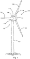
Fig. 1 eine Windenergieanlage gemäß einem bevorzugten Ausführungsbeispiel; -
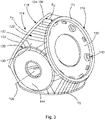
Fig. 2 eine erfindungsgemäße Rotornabe für eine Windenergieanlage in einer perspektivischen Ansicht; -
Fig. 3 die erfindungsgemäße Rotornabe gemäßFig. 2 in einer alternativen perspektivischen Ansicht; -
Fig. 4 die erfindungsgemäße Rotornabe gemäß denFiguren 2 und3 in einer perspektivischen Teilschnittansicht; -
Fig. 5 die erfindungsgemäße Rotornabe gemäß denFiguren 2 bis 4 und ein an der Rotornabe befestigtes Blattlager in einer Schnittansicht; -
Fig. 6 ein alternatives Ausführungsbeispiel einer erfindungsgemäßen Rotornabe in einer Schnittansicht.
-
1 a wind turbine according to a preferred embodiment; -
2 a rotor hub according to the invention for a wind turbine in a perspective view; -
3 the rotor hub according to the invention2 in an alternative perspective view; -
4 the rotor hub according to the inventionfigures 2 and3 in a perspective partial sectional view; -
figure 5 the rotor hub according to the inventionFigures 2 to 4 and a blade bearing attached to the rotor hub in a sectional view; -
6 an alternative embodiment of a rotor hub according to the invention in a sectional view.
Die erfindungsgemäße Rotornabe 114 ist in den
Der Flächenabschnitt 124 mit zylinderförmiger Krümmung 126 ist in jenem Bereich zwischen zwei benachbarten Flanschabschnitten 116 angeordnet, an welchem Umfänge u1, u2, u3 der benachbarten Flanschabschnitte 116 den geringsten Abstand du zueinander aufweisen. Das Gehäuse 118 der Rotornabe 114 weist benachbart zu dem Wandbereich 122 ebene Wandbereiche 128 auf. Die ebenen Wandbereiche 128 sind aus wenigstens einer dreieckigen Grundfläche 130 ausgebildet. Das Gehäuse 118 der Rotornabe 114 weist ferner benachbart zu den ebenen Wandbereichen 128 Freiformwandbereiche 132 auf. Die Freiformwandbereiche 132 sind gewölbt 134 ausgebildet. Benachbarte Wandbereiche 122, 128, 130 gehen knickfrei ineinander über.The
Wie insbesondere
Im Betrieb kommt es über ein Aufbiegen des Flanschabschnittes 116 der Rotornabe 114 zu hohen umlaufenden Ringspannungen im Lageraußenring 148 des Blattlagers 146. Dabei ist insbesondere die Lagerbohrung 156 den betreffenden Ringspannungen ausgesetzt, womit die Lagerbohrungen 156 anfällig sind für die Ausbildung von Ermüdungsrissen. Durch die Abflachung der Rotornabe 114 gegenüber einer idealen Kugelgeometrie, wie aus dem Stand der Technik bekannt, wird vorliegend der Hebelarm H zwischen der Oberfläche des Gehäuses 118 der Rotornabe 114 und der Lagerbohrung 156 des Lageraußenrings 148 bzw. den entsprechenden Lagerbefestigungsschrauben 150 reduziert, womit das Auftreten von Ermüdungsrissen im Bereich der Lagerbohrungen 156 des Lageraußenrings 148 vermieden wird.During operation, bending of the
- 100100
- Windenergieanlagewind turbine
- 102102
- TurmTower
- 104104
- Gondelgondola
- 106106
- Rotoranordnungrotor arrangement
- 108108
- Rotorblattrotor blade
- 110110
- Spinnercrackhead
- 112112
- Generatorgenerator
- 114114
- Rotornaberotor hub
- 115115
- DrehverbindungSlewing Ring
- 116116
- Flanschabschnittflange section
- 118118
- GehäuseHousing
- 120120
- Wandungwall
- 122122
- Wandbereich zwischen zwei benachbarten FlanschabschnittenWall area between two adjacent flange sections
- 124124
- Flächenabschnittarea section
- 126126
- zylinderförmige Krümmungcylindrical curvature
- 128128
- ebene Wandbereicheflat wall areas
- 130130
- dreieckige Grundflächentriangular bases
- 132132
- Freiformwandbereichfree-form wall area
- 134134
- Wölbung des FreiformwandbereichesCurvature of the free-form wall area
- 136136
- Drehachse der Nabeaxis of rotation of the hub
- 138138
- Schottbulkhead
- 140140
- Aufnahme für BlattanstellwinkelaktuatorBlade pitch actuator mount
- 142142
- Generatoranschlussflanschgenerator connection flange
- 144144
- Spinneranschlussflanschspinner connection flange
- 146146
- Blattlagersheet stock
- 148148
- Lageraußenringbearing outer ring
- 150150
- Lagerbefestigungsschraubenbearing mounting screws
- 152152
- Lagerinnenringbearing inner ring
- 154154
- Blattflanschblade flange
- 156156
- Lagerbohrung des LageraußenringsBearing bore of the bearing outer ring
- 214214
- Rotornaberotor hub
- 216216
- Flanschabschnittflange section
- 218218
- GehäuseHousing
- 220220
- Wandungwall
- 238238
- Schottbulkhead
- 256256
- Kragencollar
- duyou
- Abstand der Umfänge der FlanschabschnitteSpacing of the peripheries of the flange sections
- HH
- Hebelarmlever arm
- u1, u2, u3u1, u2, u3
- Umfänge der FlanschabschnitteCircumferences of the flange sections
Claims (13)
dadurch gekennzeichnet, dass die Rotornabe (114) drei Flanschabschnitte (116) aufweist, wobei zwischen jeweils zwei benachbarten Flanschabschnitten (116) jeweils ein Flächenabschnitt (124) mit zylinderförmiger Krümmung (126) ausgebildet ist.The rotor hub (114) of claim 1,
characterized in that the rotor hub (114) has three flange sections (116), a surface section (124) with a cylindrical curvature (126) being formed between each two adjacent flange sections (116).
dadurch gekennzeichnet, dass der Flächenabschnitt (124) mit zylinderförmiger Krümmung (126) in jenem Bereich zwischen zwei benachbarten Flanschabschnitten (116) angeordnet ist, an welchem Umfänge (u1, u2, u3) der benachbarten Flanschabschnitte (116) den geringsten Abstand (du) zueinander aufweisen.The rotor hub (114) according to claim 1 or 2,
characterized in that the surface section (124) with a cylindrical curvature (126) is arranged in that area between two adjacent flange sections (116) at which circumferences (u 1 , u 2 , u 3 ) of the adjacent flange sections (116) have the smallest distance (you) have to each other.
dadurch gekennzeichnet, dass das Gehäuse (118) der Rotornabe (114) benachbart zu dem Wandbereich (122) einen oder mehrere ebene Wandbereiche (128) aufweist, welche insbesondere aus wenigstens einer dreieckigen Grundfläche (130) ausgebildet sind.The rotor hub (114) according to the preamble of claim 1 or according to any one of the preceding claims,
characterized in that the housing (118) of the rotor hub (114) has one or more planar wall areas (128) adjacent to the wall area (122), which are formed in particular from at least one triangular base area (130).
dadurch gekennzeichnet, dass das Gehäuse (118) der Rotornabe (114) benachbart zu den ebenen Wandbereichen (128) Freiformwandbereiche (132) aufweist.The rotor hub (114) of claim 4,
characterized in that the housing (118) of the rotor hub (114) has free-form wall portions (132) adjacent to the planar wall portions (128).
dadurch gekennzeichnet, dass die Freiformwandbereiche (132) gewölbt (134) ausgebildet sind.The rotor hub (114) of claim 5,
characterized in that the free-form wall areas (132) are arched (134).
dadurch gekennzeichnet, dass benachbarte Wandbereiche (122, 128, 130) knickfrei ineinander übergehen.The rotor hub (114) according to any one of the preceding claims,
characterized in that adjacent wall areas (122, 128, 130) merge into one another without kinks.
dadurch gekennzeichnet, dass die Flächenabschnitte (124) mit zylinderförmiger Krümmung (126) zwischen sämtlichen Paarungen aus zwei Flanschabschnitten (116) ausgebildet sind.The rotor hub (114) according to any one of the preceding claims,
characterized in that the surface sections (124) are formed with a cylindrical curvature (126) between all pairs of two flange sections (116).
dadurch gekennzeichnet, dass an wenigstens einem Flanschabschnitt (216), vorzugsweise an mehreren oder sämtlichen Flanschabschnitten (216), ein Kragen (256) ausgebildet ist, welcher sich bezogen auf eine Drehachse (136) der Rotornabe (214) nach radial außen erstreckt, und wobei der Kragen (256) dazu eingerichtet ist, die Steifigkeit des Kragens (256) gegenüber Krempelmomenten zu erhöhen.The rotor hub (214) according to the preamble of claim 1 or according to any one of the preceding claims,
characterized in that a collar (256) is formed on at least one flange section (216), preferably on several or all flange sections (216), which extends radially outwards in relation to an axis of rotation (136) of the rotor hub (214), and wherein the collar (256) is adapted to increase the stiffness of the collar (256) against twisting moments.
dadurch gekennzeichnet, dass der Kragen (256) mittels einer Schraubverbindung an der Rotornabe (214) befestigt ist.The rotor hub (214) according to claim 9,
characterized in that the collar (256) is attached to the rotor hub (214) by a screw connection.
dadurch gekennzeichnet, dass der Kragen (256) einstückig mit der Rotornabe (214) ausgebildet ist, insbesondere an diese angegossen ist.The rotor hub (214) according to claim 9,
characterized in that the collar (256) is formed in one piece with the rotor hub (214), in particular cast onto it.
Applications Claiming Priority (1)
| Application Number | Priority Date | Filing Date | Title |
|---|---|---|---|
| DE102020130066 | 2020-11-13 |
Publications (1)
| Publication Number | Publication Date |
|---|---|
| EP4001635A1 true EP4001635A1 (en) | 2022-05-25 |
Family
ID=78621781
Family Applications (1)
| Application Number | Title | Priority Date | Filing Date |
|---|---|---|---|
| EP21208212.7A Pending EP4001635A1 (en) | 2020-11-13 | 2021-11-15 | Wind turbine, rotor hub for a wind turbine and related rotor assembly |
Country Status (3)
| Country | Link |
|---|---|
| US (1) | US20220154687A1 (en) |
| EP (1) | EP4001635A1 (en) |
| CN (1) | CN114483433A (en) |
Families Citing this family (1)
| Publication number | Priority date | Publication date | Assignee | Title |
|---|---|---|---|---|
| JP6728465B1 (en) * | 2019-12-25 | 2020-07-22 | 電源開発株式会社 | Wind generator |
Citations (10)
| Publication number | Priority date | Publication date | Assignee | Title |
|---|---|---|---|---|
| DE102005047629A1 (en) * | 2005-10-05 | 2007-04-12 | Irps, Hartwig | Hub of the windmill, has drive wheel whereby energy transfer from drive wheel on output shaft takes place by mechanical or magnetic contact to energy storage fastened to free-wheel |
| US7614850B2 (en) | 2006-07-11 | 2009-11-10 | General Electric Company | Apparatus for assembling rotary machines |
| US20130202448A1 (en) | 2012-02-02 | 2013-08-08 | Christian Laursen | Rotor hub for a wind turbine |
| WO2014130012A1 (en) * | 2013-02-19 | 2014-08-28 | Ramsland Arnold | Horizontal axis wind turbine with ball-and-socket hub |
| EP2947316A1 (en) | 2014-05-22 | 2015-11-25 | Mitsubishi Heavy Industries, Ltd. | Wind turbine power generating apparatus |
| US20150337796A1 (en) | 2013-08-02 | 2015-11-26 | Voith Patent Gmbh | A Turbine for a Flow Power Plant |
| EP3453871A1 (en) | 2009-12-21 | 2019-03-13 | Vestas Wind Systems A/S | A hub for a wind turbine and a method for fabricating the hub |
| WO2019197490A1 (en) * | 2018-04-11 | 2019-10-17 | Wobben Properties Gmbh | Rotor hub of a wind turbine, and method for assembling such a rotor hub |
| CN110762213A (en) * | 2019-10-31 | 2020-02-07 | 吴奕学 | Sealing rotating structure at rotating shaft in wind power generation equipment |
| EP3492734B1 (en) | 2017-12-04 | 2020-06-10 | Siemens Gamesa Renewable Energy A/S | Wind turbine and method for assembling a wind turbine |
Family Cites Families (6)
| Publication number | Priority date | Publication date | Assignee | Title |
|---|---|---|---|---|
| DE102004023773B3 (en) * | 2004-05-11 | 2005-11-17 | Repower Systems Ag | Wind turbine |
| DE102006031174B3 (en) * | 2006-07-03 | 2007-10-25 | Repower Systems Ag | Wind power plant rotor hub for rotor, has rotor blade, where hub core body and hub external body are connected by flange connection, where flange connection with pre-determined inclination is designed as rotational axis of rotor |
| DE102007014860B4 (en) * | 2007-03-26 | 2010-04-01 | Repower Systems Ag | Connection of components of a wind turbine |
| US8696315B2 (en) * | 2010-08-16 | 2014-04-15 | General Electric Company | Hub for a wind turbine and method of mounting a wind turbine |
| EP2808545B1 (en) * | 2013-05-28 | 2016-06-29 | Siemens Aktiengesellschaft | Wind turbine flange connection |
| EP3327283A1 (en) * | 2016-11-29 | 2018-05-30 | Siemens Aktiengesellschaft | Wind turbine |
-
2021
- 2021-11-12 US US17/525,457 patent/US20220154687A1/en active Pending
- 2021-11-15 CN CN202111346946.XA patent/CN114483433A/en active Pending
- 2021-11-15 EP EP21208212.7A patent/EP4001635A1/en active Pending
Patent Citations (10)
| Publication number | Priority date | Publication date | Assignee | Title |
|---|---|---|---|---|
| DE102005047629A1 (en) * | 2005-10-05 | 2007-04-12 | Irps, Hartwig | Hub of the windmill, has drive wheel whereby energy transfer from drive wheel on output shaft takes place by mechanical or magnetic contact to energy storage fastened to free-wheel |
| US7614850B2 (en) | 2006-07-11 | 2009-11-10 | General Electric Company | Apparatus for assembling rotary machines |
| EP3453871A1 (en) | 2009-12-21 | 2019-03-13 | Vestas Wind Systems A/S | A hub for a wind turbine and a method for fabricating the hub |
| US20130202448A1 (en) | 2012-02-02 | 2013-08-08 | Christian Laursen | Rotor hub for a wind turbine |
| WO2014130012A1 (en) * | 2013-02-19 | 2014-08-28 | Ramsland Arnold | Horizontal axis wind turbine with ball-and-socket hub |
| US20150337796A1 (en) | 2013-08-02 | 2015-11-26 | Voith Patent Gmbh | A Turbine for a Flow Power Plant |
| EP2947316A1 (en) | 2014-05-22 | 2015-11-25 | Mitsubishi Heavy Industries, Ltd. | Wind turbine power generating apparatus |
| EP3492734B1 (en) | 2017-12-04 | 2020-06-10 | Siemens Gamesa Renewable Energy A/S | Wind turbine and method for assembling a wind turbine |
| WO2019197490A1 (en) * | 2018-04-11 | 2019-10-17 | Wobben Properties Gmbh | Rotor hub of a wind turbine, and method for assembling such a rotor hub |
| CN110762213A (en) * | 2019-10-31 | 2020-02-07 | 吴奕学 | Sealing rotating structure at rotating shaft in wind power generation equipment |
Also Published As
| Publication number | Publication date |
|---|---|
| US20220154687A1 (en) | 2022-05-19 |
| CN114483433A (en) | 2022-05-13 |
Similar Documents
| Publication | Publication Date | Title |
|---|---|---|
| EP1398499B1 (en) | Attachment of rotor blades to the hub of a wind turbine | |
| EP2273101B1 (en) | Assembly process for rotorblades of a wind turbine | |
| DE102006031174B3 (en) | Wind power plant rotor hub for rotor, has rotor blade, where hub core body and hub external body are connected by flange connection, where flange connection with pre-determined inclination is designed as rotational axis of rotor | |
| EP1975405B1 (en) | Connection of elements of a wind turbine plant, use thereof and method | |
| DE102005059298C5 (en) | System and method for passive load reduction in a wind turbine | |
| EP1636490B1 (en) | Rotor blade connection | |
| EP2882962B1 (en) | Rotor shaft for a wind turbine | |
| EP3455493B1 (en) | Wind-turbine rotor blade, and wind turbine having same | |
| DE102013101233A1 (en) | Root end arrangement configuration for a wind turbine rotor blade and related manufacturing methods | |
| EP2154367B1 (en) | Method of assembling a rotor hub on a rotor shaft for a wind energy system and wind energy system | |
| EP3469212A1 (en) | Rotor for a wind turbine, rotor blade for a wind turbine, sleeve, and method for assembling a rotor | |
| EP1024081A2 (en) | Blade root for propellers and rotor blades | |
| EP2831413B1 (en) | Wind turbine comprising gearbox supporting means and method for maintaining said gearbox supporting means | |
| EP4001635A1 (en) | Wind turbine, rotor hub for a wind turbine and related rotor assembly | |
| EP3333439B1 (en) | Method for exchanging a used bearing, in particular for replacing a large bearing, such as the main bearing of a wind turbine and bearing arrangement | |
| EP3728835B1 (en) | Wind turbine comprising a rotor hub extension | |
| DE102013003634A1 (en) | Wind turbine rotor blade with a blade connection area | |
| EP3925872A1 (en) | Wrapped rotor | |
| EP3431749B1 (en) | Extender for fixing a rotor blade to a rotor hub housing of a wind turbine, method for producing an extender and method for mounting an extender | |
| DE102017223614A1 (en) | Wind turbine, rotor system, method of using a wind turbine | |
| DE102021120793A1 (en) | Vertical wind turbine with resistance rotor | |
| EP4286684A2 (en) | Rotor bearing housing, rotor bearing assembly and wind turbine | |
| DE102018206099A1 (en) | Wind turbine, rotor system, method of using a wind turbine, method of making a wind turbine | |
| DE102019220197A1 (en) | Machine train for wind turbines, wind turbine | |
| WO2018108525A1 (en) | Wind turbine having large rolling bearing and method for the assembly thereof |
Legal Events
| Date | Code | Title | Description |
|---|---|---|---|
| PUAI | Public reference made under article 153(3) epc to a published international application that has entered the european phase |
Free format text: ORIGINAL CODE: 0009012 |
|
| STAA | Information on the status of an ep patent application or granted ep patent |
Free format text: STATUS: THE APPLICATION HAS BEEN PUBLISHED |
|
| AK | Designated contracting states |
Kind code of ref document: A1 Designated state(s): AL AT BE BG CH CY CZ DE DK EE ES FI FR GB GR HR HU IE IS IT LI LT LU LV MC MK MT NL NO PL PT RO RS SE SI SK SM TR |
|
| STAA | Information on the status of an ep patent application or granted ep patent |
Free format text: STATUS: REQUEST FOR EXAMINATION WAS MADE |
|
| 17P | Request for examination filed |
Effective date: 20221125 |
|
| RBV | Designated contracting states (corrected) |
Designated state(s): AL AT BE BG CH CY CZ DE DK EE ES FI FR GB GR HR HU IE IS IT LI LT LU LV MC MK MT NL NO PL PT RO RS SE SI SK SM TR |