EP4001628A1 - A method for controlling injection in a combustion engine - Google Patents
A method for controlling injection in a combustion engine Download PDFInfo
- Publication number
- EP4001628A1 EP4001628A1 EP20207991.9A EP20207991A EP4001628A1 EP 4001628 A1 EP4001628 A1 EP 4001628A1 EP 20207991 A EP20207991 A EP 20207991A EP 4001628 A1 EP4001628 A1 EP 4001628A1
- Authority
- EP
- European Patent Office
- Prior art keywords
- engine
- combustion chamber
- operational mode
- fuel
- water
- Prior art date
- Legal status (The legal status is an assumption and is not a legal conclusion. Google has not performed a legal analysis and makes no representation as to the accuracy of the status listed.)
- Pending
Links
Images


Classifications
-
- F—MECHANICAL ENGINEERING; LIGHTING; HEATING; WEAPONS; BLASTING
- F02—COMBUSTION ENGINES; HOT-GAS OR COMBUSTION-PRODUCT ENGINE PLANTS
- F02D—CONTROLLING COMBUSTION ENGINES
- F02D41/00—Electrical control of supply of combustible mixture or its constituents
- F02D41/0025—Controlling engines characterised by use of non-liquid fuels, pluralities of fuels, or non-fuel substances added to the combustible mixtures
- F02D41/0027—Controlling engines characterised by use of non-liquid fuels, pluralities of fuels, or non-fuel substances added to the combustible mixtures the fuel being gaseous
-
- F—MECHANICAL ENGINEERING; LIGHTING; HEATING; WEAPONS; BLASTING
- F02—COMBUSTION ENGINES; HOT-GAS OR COMBUSTION-PRODUCT ENGINE PLANTS
- F02D—CONTROLLING COMBUSTION ENGINES
- F02D19/00—Controlling engines characterised by their use of non-liquid fuels, pluralities of fuels, or non-fuel substances added to the combustible mixtures
- F02D19/02—Controlling engines characterised by their use of non-liquid fuels, pluralities of fuels, or non-fuel substances added to the combustible mixtures peculiar to engines working with gaseous fuels
- F02D19/021—Control of components of the fuel supply system
- F02D19/023—Control of components of the fuel supply system to adjust the fuel mass or volume flow
- F02D19/024—Control of components of the fuel supply system to adjust the fuel mass or volume flow by controlling fuel injectors
-
- F—MECHANICAL ENGINEERING; LIGHTING; HEATING; WEAPONS; BLASTING
- F02—COMBUSTION ENGINES; HOT-GAS OR COMBUSTION-PRODUCT ENGINE PLANTS
- F02M—SUPPLYING COMBUSTION ENGINES IN GENERAL WITH COMBUSTIBLE MIXTURES OR CONSTITUENTS THEREOF
- F02M21/00—Apparatus for supplying engines with non-liquid fuels, e.g. gaseous fuels stored in liquid form
- F02M21/02—Apparatus for supplying engines with non-liquid fuels, e.g. gaseous fuels stored in liquid form for gaseous fuels
- F02M21/0203—Apparatus for supplying engines with non-liquid fuels, e.g. gaseous fuels stored in liquid form for gaseous fuels characterised by the type of gaseous fuel
- F02M21/0206—Non-hydrocarbon fuels, e.g. hydrogen, ammonia or carbon monoxide
-
- F—MECHANICAL ENGINEERING; LIGHTING; HEATING; WEAPONS; BLASTING
- F02—COMBUSTION ENGINES; HOT-GAS OR COMBUSTION-PRODUCT ENGINE PLANTS
- F02B—INTERNAL-COMBUSTION PISTON ENGINES; COMBUSTION ENGINES IN GENERAL
- F02B41/00—Engines characterised by special means for improving conversion of heat or pressure energy into mechanical power
- F02B41/02—Engines with prolonged expansion
- F02B41/06—Engines with prolonged expansion in compound cylinders
-
- F—MECHANICAL ENGINEERING; LIGHTING; HEATING; WEAPONS; BLASTING
- F02—COMBUSTION ENGINES; HOT-GAS OR COMBUSTION-PRODUCT ENGINE PLANTS
- F02D—CONTROLLING COMBUSTION ENGINES
- F02D19/00—Controlling engines characterised by their use of non-liquid fuels, pluralities of fuels, or non-fuel substances added to the combustible mixtures
- F02D19/02—Controlling engines characterised by their use of non-liquid fuels, pluralities of fuels, or non-fuel substances added to the combustible mixtures peculiar to engines working with gaseous fuels
- F02D19/021—Control of components of the fuel supply system
- F02D19/022—Control of components of the fuel supply system to adjust the fuel pressure, temperature or composition
-
- F—MECHANICAL ENGINEERING; LIGHTING; HEATING; WEAPONS; BLASTING
- F02—COMBUSTION ENGINES; HOT-GAS OR COMBUSTION-PRODUCT ENGINE PLANTS
- F02D—CONTROLLING COMBUSTION ENGINES
- F02D19/00—Controlling engines characterised by their use of non-liquid fuels, pluralities of fuels, or non-fuel substances added to the combustible mixtures
- F02D19/02—Controlling engines characterised by their use of non-liquid fuels, pluralities of fuels, or non-fuel substances added to the combustible mixtures peculiar to engines working with gaseous fuels
- F02D19/026—Measuring or estimating parameters related to the fuel supply system
- F02D19/027—Determining the fuel pressure, temperature or volume flow, the fuel tank fill level or a valve position
-
- F—MECHANICAL ENGINEERING; LIGHTING; HEATING; WEAPONS; BLASTING
- F02—COMBUSTION ENGINES; HOT-GAS OR COMBUSTION-PRODUCT ENGINE PLANTS
- F02D—CONTROLLING COMBUSTION ENGINES
- F02D19/00—Controlling engines characterised by their use of non-liquid fuels, pluralities of fuels, or non-fuel substances added to the combustible mixtures
- F02D19/12—Controlling engines characterised by their use of non-liquid fuels, pluralities of fuels, or non-fuel substances added to the combustible mixtures peculiar to engines working with non-fuel substances or with anti-knock agents, e.g. with anti-knock fuel
-
- F—MECHANICAL ENGINEERING; LIGHTING; HEATING; WEAPONS; BLASTING
- F02—COMBUSTION ENGINES; HOT-GAS OR COMBUSTION-PRODUCT ENGINE PLANTS
- F02D—CONTROLLING COMBUSTION ENGINES
- F02D29/00—Controlling engines, such controlling being peculiar to the devices driven thereby, the devices being other than parts or accessories essential to engine operation, e.g. controlling of engines by signals external thereto
- F02D29/02—Controlling engines, such controlling being peculiar to the devices driven thereby, the devices being other than parts or accessories essential to engine operation, e.g. controlling of engines by signals external thereto peculiar to engines driving vehicles; peculiar to engines driving variable pitch propellers
-
- F—MECHANICAL ENGINEERING; LIGHTING; HEATING; WEAPONS; BLASTING
- F02—COMBUSTION ENGINES; HOT-GAS OR COMBUSTION-PRODUCT ENGINE PLANTS
- F02D—CONTROLLING COMBUSTION ENGINES
- F02D41/00—Electrical control of supply of combustible mixture or its constituents
- F02D41/0025—Controlling engines characterised by use of non-liquid fuels, pluralities of fuels, or non-fuel substances added to the combustible mixtures
-
- F—MECHANICAL ENGINEERING; LIGHTING; HEATING; WEAPONS; BLASTING
- F02—COMBUSTION ENGINES; HOT-GAS OR COMBUSTION-PRODUCT ENGINE PLANTS
- F02D—CONTROLLING COMBUSTION ENGINES
- F02D41/00—Electrical control of supply of combustible mixture or its constituents
- F02D41/30—Controlling fuel injection
- F02D41/38—Controlling fuel injection of the high pressure type
-
- F—MECHANICAL ENGINEERING; LIGHTING; HEATING; WEAPONS; BLASTING
- F02—COMBUSTION ENGINES; HOT-GAS OR COMBUSTION-PRODUCT ENGINE PLANTS
- F02M—SUPPLYING COMBUSTION ENGINES IN GENERAL WITH COMBUSTIBLE MIXTURES OR CONSTITUENTS THEREOF
- F02M21/00—Apparatus for supplying engines with non-liquid fuels, e.g. gaseous fuels stored in liquid form
- F02M21/02—Apparatus for supplying engines with non-liquid fuels, e.g. gaseous fuels stored in liquid form for gaseous fuels
- F02M21/0218—Details on the gaseous fuel supply system, e.g. tanks, valves, pipes, pumps, rails, injectors or mixers
- F02M21/0221—Fuel storage reservoirs, e.g. cryogenic tanks
- F02M21/0224—Secondary gaseous fuel storages
-
- F—MECHANICAL ENGINEERING; LIGHTING; HEATING; WEAPONS; BLASTING
- F02—COMBUSTION ENGINES; HOT-GAS OR COMBUSTION-PRODUCT ENGINE PLANTS
- F02M—SUPPLYING COMBUSTION ENGINES IN GENERAL WITH COMBUSTIBLE MIXTURES OR CONSTITUENTS THEREOF
- F02M21/00—Apparatus for supplying engines with non-liquid fuels, e.g. gaseous fuels stored in liquid form
- F02M21/02—Apparatus for supplying engines with non-liquid fuels, e.g. gaseous fuels stored in liquid form for gaseous fuels
- F02M21/0218—Details on the gaseous fuel supply system, e.g. tanks, valves, pipes, pumps, rails, injectors or mixers
- F02M21/023—Valves; Pressure or flow regulators in the fuel supply or return system
- F02M21/0239—Pressure or flow regulators therefor
-
- F—MECHANICAL ENGINEERING; LIGHTING; HEATING; WEAPONS; BLASTING
- F02—COMBUSTION ENGINES; HOT-GAS OR COMBUSTION-PRODUCT ENGINE PLANTS
- F02M—SUPPLYING COMBUSTION ENGINES IN GENERAL WITH COMBUSTIBLE MIXTURES OR CONSTITUENTS THEREOF
- F02M21/00—Apparatus for supplying engines with non-liquid fuels, e.g. gaseous fuels stored in liquid form
- F02M21/02—Apparatus for supplying engines with non-liquid fuels, e.g. gaseous fuels stored in liquid form for gaseous fuels
- F02M21/0218—Details on the gaseous fuel supply system, e.g. tanks, valves, pipes, pumps, rails, injectors or mixers
- F02M21/0245—High pressure fuel supply systems; Rails; Pumps; Arrangement of valves
-
- F—MECHANICAL ENGINEERING; LIGHTING; HEATING; WEAPONS; BLASTING
- F02—COMBUSTION ENGINES; HOT-GAS OR COMBUSTION-PRODUCT ENGINE PLANTS
- F02M—SUPPLYING COMBUSTION ENGINES IN GENERAL WITH COMBUSTIBLE MIXTURES OR CONSTITUENTS THEREOF
- F02M25/00—Engine-pertinent apparatus for adding non-fuel substances or small quantities of secondary fuel to combustion-air, main fuel or fuel-air mixture
- F02M25/022—Adding fuel and water emulsion, water or steam
- F02M25/0227—Control aspects; Arrangement of sensors; Diagnostics; Actuators
-
- F—MECHANICAL ENGINEERING; LIGHTING; HEATING; WEAPONS; BLASTING
- F02—COMBUSTION ENGINES; HOT-GAS OR COMBUSTION-PRODUCT ENGINE PLANTS
- F02M—SUPPLYING COMBUSTION ENGINES IN GENERAL WITH COMBUSTIBLE MIXTURES OR CONSTITUENTS THEREOF
- F02M25/00—Engine-pertinent apparatus for adding non-fuel substances or small quantities of secondary fuel to combustion-air, main fuel or fuel-air mixture
- F02M25/022—Adding fuel and water emulsion, water or steam
- F02M25/025—Adding water
- F02M25/028—Adding water into the charge intakes
-
- F—MECHANICAL ENGINEERING; LIGHTING; HEATING; WEAPONS; BLASTING
- F02—COMBUSTION ENGINES; HOT-GAS OR COMBUSTION-PRODUCT ENGINE PLANTS
- F02M—SUPPLYING COMBUSTION ENGINES IN GENERAL WITH COMBUSTIBLE MIXTURES OR CONSTITUENTS THEREOF
- F02M25/00—Engine-pertinent apparatus for adding non-fuel substances or small quantities of secondary fuel to combustion-air, main fuel or fuel-air mixture
- F02M25/022—Adding fuel and water emulsion, water or steam
- F02M25/025—Adding water
- F02M25/03—Adding water into the cylinder or the pre-combustion chamber
-
- F—MECHANICAL ENGINEERING; LIGHTING; HEATING; WEAPONS; BLASTING
- F02—COMBUSTION ENGINES; HOT-GAS OR COMBUSTION-PRODUCT ENGINE PLANTS
- F02D—CONTROLLING COMBUSTION ENGINES
- F02D41/00—Electrical control of supply of combustible mixture or its constituents
- F02D41/30—Controlling fuel injection
- F02D41/38—Controlling fuel injection of the high pressure type
- F02D2041/389—Controlling fuel injection of the high pressure type for injecting directly into the cylinder
-
- F—MECHANICAL ENGINEERING; LIGHTING; HEATING; WEAPONS; BLASTING
- F02—COMBUSTION ENGINES; HOT-GAS OR COMBUSTION-PRODUCT ENGINE PLANTS
- F02D—CONTROLLING COMBUSTION ENGINES
- F02D2200/00—Input parameters for engine control
- F02D2200/02—Input parameters for engine control the parameters being related to the engine
- F02D2200/06—Fuel or fuel supply system parameters
- F02D2200/0602—Fuel pressure
-
- F—MECHANICAL ENGINEERING; LIGHTING; HEATING; WEAPONS; BLASTING
- F02—COMBUSTION ENGINES; HOT-GAS OR COMBUSTION-PRODUCT ENGINE PLANTS
- F02M—SUPPLYING COMBUSTION ENGINES IN GENERAL WITH COMBUSTIBLE MIXTURES OR CONSTITUENTS THEREOF
- F02M25/00—Engine-pertinent apparatus for adding non-fuel substances or small quantities of secondary fuel to combustion-air, main fuel or fuel-air mixture
- F02M25/022—Adding fuel and water emulsion, water or steam
- F02M25/0221—Details of the water supply system, e.g. pumps or arrangement of valves
- F02M25/0222—Water recovery or storage
-
- Y—GENERAL TAGGING OF NEW TECHNOLOGICAL DEVELOPMENTS; GENERAL TAGGING OF CROSS-SECTIONAL TECHNOLOGIES SPANNING OVER SEVERAL SECTIONS OF THE IPC; TECHNICAL SUBJECTS COVERED BY FORMER USPC CROSS-REFERENCE ART COLLECTIONS [XRACs] AND DIGESTS
- Y02—TECHNOLOGIES OR APPLICATIONS FOR MITIGATION OR ADAPTATION AGAINST CLIMATE CHANGE
- Y02T—CLIMATE CHANGE MITIGATION TECHNOLOGIES RELATED TO TRANSPORTATION
- Y02T10/00—Road transport of goods or passengers
- Y02T10/10—Internal combustion engine [ICE] based vehicles
- Y02T10/30—Use of alternative fuels, e.g. biofuels
Definitions
- the present invention relates to a method for controlling injection of a gaseous fuel, such as hydrogen or a hydrogen based gas, and a water-based fluid medium into a combustion engine.
- the invention further relates to an injection system, a combustion engine and a vehicle.
- the invention is applicable on vehicles, in particularly heavy vehicles, such as e.g. trucks.
- the invention will mainly be described in relation to a truck, the internal combustion engine is of course also applicable for other type of vehicles, such as cars, industrial construction machines, wheel loaders, etc.
- US 967,828 discloses an internal combustion engine with an object of minimizing the number of cylinders and moving parts required to perform an engine cycle.
- the internal combustion engine in US 967,828 comprises a high-pressure cylinder and a low-pressure cylinder, which are connected to each other by means of two conduits.
- the low-pressure cylinder is equipped to alternately perform the functions of a compressor and an expander.
- the need of a separate compressor and a separate expander is reduced, and the internal combustion engine can be made relatively compact.
- a method for controlling injection of a gaseous fuel, such as hydrogen or a hydrogen based gas, and a water-based fluid medium into a combustion engine comprises the steps of:
- gaseous fuel By reducing the pressure inside the combustion chamber, gaseous fuel can be injected via the fuel inlet to the combustion chamber even though the fuel pressure in the pressurised tank(s) supplying the gaseous fuel have been reduced to a level which otherwise would prevent operating the engine according to the first operational mode, i.e. when injecting gaseous fuel at the relatively high pressure.
- a problem when operating a combustion engine with gaseous fuel supplied by pressurised tank(s), is that when the pressure in the pressurised tank(s) is reduced as the pressurised tank(s) begins to be depleted, the gaseous fuel is no longer available at a pressure which enables normal operation of the combustion engine.
- the present invention provides a solution by lowering the pressure in the combustion chamber, and thereby being able to supply gaseous fuel at a relatively low pressure to the combustion chamber.
- more fuel in the pressurised fuel tank(s) can used before re-fuelling and/or the need of a separate compressor for increasing the pressure of the gaseous fuel can be avoided.
- the same fuel inlet is used in the first operational mode as in the second operational mode.
- undesirable knocking of the gaseous fuel can be avoided during the compression stroke of the engine.
- the water based fluid medium which is optionally injected in the first operational mode may be water either as liquid or steam.
- the water based fluid medium comprises at least 50 % water molecules, for example more than 70 % water molecules, such as e.g. more than 90 %, or more than 95 %, or approximately 100 % of water molecules.
- the water based fluid medium may be referred to as a fluid medium containing water (here fluid medium refers to both liquid and gaseous phases, but not solid state).
- the injection of the water based fluid medium in the first operational mode is optional, and may thus not be performed.
- the gaseous fuel is injected into the combustion chamber of the engine at the relatively high pressure, and is subsequently combusted by e.g. diffusion compression or compression ignition.
- the gaseous fuel is being supplied to the combustion chamber by at least one pressurised tank.
- the gaseous fuel is being supplied to the combustion chamber by at least two pressurised tanks, being configured to individually supply gaseous fuel to the combustion chamber.
- the same pressurised tank is at least partly used in the first and second operational modes.
- the gaseous fuel is supplied to the combustion chamber by at least one pressurized tank, and the method further comprises the step of changing the operational mode of the engine from the first operational mode to the second operational mode when the available fuel pressure in the pressurised tank prevent injection of gaseous fuel at said relatively high pressure.
- the method further comprises the step of monitoring the fuel pressure in the pressurized tank, and wherein the step of changing the operational mode of the engine is carried out in response to a decrease in fuel pressure below a threshold value.
- the operational mode of the engine may be switched or changed from the first operational mode to the second operational mode in an efficient and timely way.
- a specific threshold value a repetitive and reliable operation of the engine is achieved.
- the changing of operational modes of the engine is performed during a gear change to smoothen the change of operational modes of the engine.
- a gear change will be activated when the engine demands, or call for, a change in operational mode.
- the engine will postpone the change of operational mode after receiving a signal that the threshold value is met, to the next gear change.
- the compressor boost of the engine is reduced prior to, or simultaneously with the change of operational mode of the engine.
- the engine further comprises an intake passage for intake of compressed air into the combustion chamber, the intake passage being regulated by an intake valve, and wherein the method further comprises the step of, in said second operational mode, closing the intake valve subsequent to injecting water as liquid into the engine.
- the liquid may evaporate as it cool down the environment inside of the engine, and thereby also specifically reduce the pressure inside the combustion chamber, without contributing significantly to a pressure increase (due to water liquid evaporation) of the combustion chamber.
- the generated steam from the injected liquid water is distributed inside a relatively large area within the engine, and thus does not cause a significant increase of pressure inside the combustion chamber, which would counteract the pressure decrease caused by the cooling effect of the injected liquid water.
- the injection of water as liquid into engine in the second operational mode is carried out during an intake stroke of the engine.
- the step of injecting water as liquid into the engine in said second operational mode comprises injecting water upstream of said combustion chamber or injecting water into the combustion chamber.
- the water may be injected as liquid into a compressor, or compressor portion, of the engine.
- This provides for an efficient way of introducing water as liquid into the engine, as well as providing an effective pressure and temperature reduction of the combustion chamber (as the compressor is in fluid communication with the combustion chamber, at least prior to closing the intake valve of the intake air passage).
- the injection occurs closer to the point of interest of the temperature and pressure reduction compared to injecting water as liquid upstream of the combustion chamber.
- the step of injecting water as liquid into the engine in said second operational mode comprises injecting water upstream of said combustion chamber in combination with injecting water into the combustion chamber.
- the method further comprises the step of, in said second operational mode, combusting the gaseous fuel by spark plug ignition.
- the gaseous fuel is combusted by the aid of a spark plug.
- an efficient combustion can be achieved, even though the pressure and temperature in the combustion chamber has been reduced.
- the method further comprises carrying out the second operational mode in accordance with the Otto-cycle.
- the step of injection water as liquid in the second operational mode is to at least control the knocking of the fuel combustion.
- the method further comprises the step of, in said first operational mode, combusting the gaseous fuel by diffusion combustion or compression ignition.
- a conventional compression based combustion can be achieved during normal operation of the engine, i.e. in the first operational mode.
- the step of injecting the gaseous fuel and optionally water-based fluid medium into the combustion chamber in said first operational mode comprises injecting the water-based fluid as steam, e.g. as water steam.
- Using steam to complement the injection of gaseous fuel in the combustion chamber is advantageous for many reasons, e.g. for mixing of the gaseous fuel in the combustion chamber.
- the water based fluid medium is injected as liquid in the first operational mode.
- the water liquid will typically instantly be vaporised. Such instant evaporation may e.g. be beneficial from a mixing perspective.
- the step of injecting the gaseous fuel and optionally water-based fluid medium into the combustion chamber in said first operational mode comprises injecting the gaseous fuel into the combustion chamber prior to injecting the water-based fluid medium into the combustion chamber.
- the water-based fluid medium may be injected into the combustion chamber prior to, or simultaneously with (e.g. in an overlapping manner), injecting the gaseous fuel into the combustion chamber. Or, as stated above, the injection of the water-based fluid medium in the first operational mode is omitted.
- exhaust gas recirculation in the first operational mode, is utilized e.g. to reduce the NOx.
- Such exhaust gas recirculation typically produces water as condensate, which water may be used in the second operational mode.
- the combustion engine comprises a piston having a head, the piston being configured for reciprocal movement within a cylinder of the engine, and wherein the combustion chamber is comprised in the cylinder above the head of the piston.
- the step of injecting the gaseous fuel into the combustion chamber in the second operational mode is performed further away from a top dead center compared to the injection of gaseous fuel into the combustion chamber in the first operational mode.
- the combustion in the first operational mode may cause the mix of gaseous fuel and steam to combust at the movement when the piston passes a top dead center, TDC, for example, within 10 crank angel degrees, CAD, of the TDC.
- the amount of gaseous fuel and any water based fluid medium are predetermined.
- a predetermined volume of the gaseous fuel, as well as a predetermined volume of the water based fluid medium, are fed to the engine.
- an injection system for a combustion engine having a combustion chamber comprises:
- the water inlet arrangement comprises a first water inlet configured to inject the water based fluid medium into the combustion chamber, and/or a second water inlet configured to inject the water based fluid medium into the engine upstream of the combustion chamber.
- the first water inlet may be omitted.
- the second water inlet is used for injecting the water as liquid during the second operational mode.
- the first water inlet is configured to inject the water based fluid medium as steam (e.g. in the first and/or second operational mode).
- the second water inlet is configured to inject the water based fluid medium as liquid.
- the injection system is configured to, in the first operational mode, inject the gaseous fuel into the combustion chamber prior to injecting any water based fluid medium as steam into the combustion chamber.
- the injection system comprises a common injector comprising said fuel inlet, and at least the first water inlet.
- a combustion engine such as e.g. an internal combustion engine
- the combustion engine comprises the injection system according to the second aspect of the invention.
- the engine may typically further comprise a combustion chamber and other related components as described with reference to the first aspect of the invention. The effects related to such embodiments are not repeated here again.
- the combustion engine further comprises an intake passage for intake of compressed air into the combustion chamber, and an intake valve configured to regulate fluid flow in the intake passage, wherein the injection system is configured to, in the second operational mode, inject water into the engine prior to closing the intake valve.
- the combustion engine further comprising a spark plug arranged in the combustion chamber, wherein the spark plug is arranged to ignite the gaseous fuel in the second operational mode.
- the combustion engine further comrsies a cylinder and a piston having a head, the piston being configured for reciprocal movement within the cylinder, and wherein the combustion chamber is comprised in the cylinder above the head of the piston, and wherein the engine is configured to compress the gaseous fuel in the first operational mode to achieve a compression ignition.
- the combustion engine is configured to, in said second operational mode, inject the gaseous fuel into the combustion chamber further away from a top dead center of the piston, compared to the injection of gaseous fuel into the combustion chamber in the first operational mode.
- a vehicle comprising a combustion engine.
- the vehicle comprises an electrical control unit configured to perform the method according to the first aspect of the invention, the injection system according to the second aspect of the invention, or the combustion engine according to the third aspect of the invention.
- the vehicle comprises at least two pressurised fuel tanks, the fuel tanks being individually fluidly connected to a fuel inlet of the injection system to the engine, and a pressure control unit configured to control which of the fuel tanks that supply pressurised fuel flow to the fuel inlet, the pressure control unit being further configured to successively empty the fuel tanks such that at least one fuel tank is kept at a relatively higher pressure than the other.
- the vehicle includes several pressurised tanks for supplying the gaseous fuel, in which some are actively kept at high pressure (to be used according to the first operational mode of the vehicle) when the total fuel volume in the tanks are being depleted.
- the vehicle can operate in accordance with the first operational mode longer compared to scenario in which the pressurised tanks are used in such a way that the pressure in the pressurised tanks are evenly distributed.
- a vehicle 1 with an internal combustion engine 100 there is provided a vehicle 1 with an internal combustion engine 100 according to the present invention.
- the vehicle 1 depicted in Fig. 1 is a truck for which the internal combustion engine 100, which will be described in detail below, is particularly suitable for.
- the internal combustion engine 100 may as well be implemented in other types of vehicles, such as in busses, light-weight trucks, passenger cars, marine applications etc.
- the internal combustion engine 100 may be a so-called clean engine, and be operated on a gaseous fuel such as e.g. hydrogen, and may thus be referred to as a H2 engine.
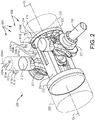
- FIG. 2 illustrate an internal combustion engine 200 according to an example embodiment of the present invention.
- a full illustration of each cylinder which houses a respective piston has been omitted from Fig. 2 for simplicity of understanding the invention and the fluid flow configurations.
- the internal combustion engine 200 comprises a first combustion cylinder 210 housing a first combustion piston 212, and a second combustion cylinder 214 housing a second combustion piston 216.
- the internal combustion engine 200 further comprises a compressor cylinder 230 housing a compressor piston 232, and an expander cylinder 220 housing an expander piston 222.
- the first and second combustion pistons 212, 216 are individually arranged inside the first and second combustion cylinders 210, 212, respectively, and are adapted for reciprocating motion therein.
- the compressor piston 232 and the expander piston 222 are arranged inside the compressor cylinder 230 and the expander cylinder 220, respectively, and are adapted for reciprocating motion therein.
- the internal combustion engine 200 comprises a crank shaft 240, and a compressor piston connecting rod (not shown) connecting the compressor piston 232 to the crankshaft 240.
- a first combustion piston connecting rod 213 connects the first combustion piston 212 to the crankshaft 240
- a second combustion piston connecting rod 217 connects the second combustion piston 214 to the crankshaft 240.
- the compressor piston 232 is connected to the expander piston 222 by at least one connecting element 250.
- the connecting element 250 rigidly connects the compressor piston 232 to the expander piston 222, such that the compressor piston 232 and the expander piston 222 move in unison.
- the compressor piston 232 moves in a downstroke (i.e. in order to compress the air in the compressor cylinder 230)
- the expander piston 222 moves in a stroke following the motion of the compressor piston 232.
- the expander piston 222 moves in an upstroke
- the compressor piston 232 moves in a stroke following the motion of the expander piston 222.
- other configurations e.g. in which the expander piston 222 is directly connected to the crankshaft 240 via an expander connecting rod, is within the scope of the invention.
- the compressor cylinder 230 and the expander cylinder 220 are positioned on opposite sides of, and in close proximity to, the crankshaft 240.
- a portion of said crankshaft 240 is arranged in between the expander piston 222 and the compressor piston 232, such that the portion is arranged between respective crankshaft facing surfaces of the expander piston 222 and the compressor piston 232.
- the expander piston 222 is configured for a reciprocating motion inside of the expander cylinder 220 along an expander axis EA.
- the compressor piston 232 is configured for a reciprocating motion inside of the compressor cylinder 230 along a compressor axis CA.
- the first combustion pistons 212 is configured for a reciprocating motion inside of the first combustion cylinder 210 along a combustion axis CoA1
- the second combustion pistons 216 is configured for a reciprocating motion inside of the second combustion cylinder 214 along a combustion axis CoA2.
- the expander cylinder 220 and the compressor cylinder 230 are co-axially arranged, i.e. the expander axis EA and the compressor axis CA are aligned.
- first combustion cylinder 210, and the second combustion cylinder 214 are protruding laterally from said crankshaft 240 compared to the expander cylinder 220.
- the compressor cylinder 230, and the first and second combustion cylinders 210, 214 are arranged inside the internal combustion engine 200 in such way that the compressor axis CA is angled in relation to each one of the combustion axis CoA1 , CoA2 by e.g. 90 degrees, or between 40 degrees and 90 degrees, such as between 50 degrees and 75 degrees, or between 55 degrees and 65 degrees, such as e.g. about 60 degrees.
- the engine 200 comprises an injection system 620 comprising first and second fuel inlets 603A, 603B configured to supply gaseous fuel to the first and second combustion cylinders 210, 214 (typically into the respective combustion chamber arranged between a head of the respective combustion piston and the respective combustion cylinder).
- Each one of the fuel inlets 603A, 603B is fluidly connected to at least one pressurised tank (as shown in e.g. Fig. 3 ).
- the gaseous fuel is preferably hydrogen, or a hydrogen based gas, and the pressurised tanks are thus preferably charged with hydrogen, or a hydrogen based gas (or a fuel which easily can conform to form hydrogen).
- the injection system 620 further comprises a water inlet arrangement 604 configured to supply a water based fluid medium to the engine 200.
- the water inlet arrangement 604 comprises a first cylinder water inlet 604A configured to inject the water based fluid medium into the first combustion cylinder 210, a second cylinder water inlet 604B configured to inject the water based fluid medium into the second combustion cylinder 214, and a compressor water inlet 604C configured to inject the water based fluid medium into the compressor cylinder 230.
- the first and second cylinder water inlets 604A, 604B are typically configured to inject the water based fluid medium into the respective combustion cylinders 210, 214 as steam (e.g. water steam), and the compressor water inlet 604C is arranged and configured to inject the water based fluid medium into the compressor cylinder 230 as liquid water.
- each one of the combustion cylinders 210, 214 of the engine 200 of Fig. 2 comprises an intake passage 615A, 615B, which is regulated by a respective intake valve 616A, 616B.
- compressed air can be fed from the compressor cylinder 230 to the combustion chambers of the combustion cylinders 210, 214.
- FIG. 3 schematically illustrates an internal combustion engine 300 according to an example embodiment of the present invention.
- the internal combustion engine 300 of Fig. 3 may have a corresponding configuration as the internal combustion engine 200 of Fig. 2 .
- Fig. 3 only one combustion piston and combustion cylinder are shown for simplicity reasons.
- the internal combustion engine 300 comprises a combustion cylinder 310 housing a first combustion piston 312, a compressor 330 (wherein the compressor cylinder and compressor piston are not shown separately) and an expander 320 (wherein the expander cylinder and the expander piston are not shown separately).
- the configuration with the combustion cylinder(s) 310, the compressor 330 and the expander 320 may be the same as that shown in Fig. 2 .
- the combustion piston 312 includes a head 313 wherein the piston 312 is configured for reciprocal movement within the combustion cylinder 310 and wherein a combustion chamber 314 is comprised in the combustion cylinder 310 above the head 313 of the combustion piston 312.
- the engine 300 further comprising a spark plug 309 arranged in the combustion chamber 314.
- the engine 300 comprises an air chamber 311 fluidly connecting the compressor 330 and the combustion chamber 314 (i.e. the air chamber 311 is arranged upstream of the combustion chamber 314). Compressed air is fed to the combustion chamber 314 via an intake passage 315, and is regulated by an intake valve 316.
- the engine 300 of Fig. 3 comprises a heat exchanger 305 arranged downstream of, and in fluid communication with, the combustion chamber 314 for receiving exhaust gas from the combustion chamber 314.
- the heat exchanger 305 houses a three-way catalytic converter 306 arranged in downstream fluid communication with the combustion chamber 314 for receiving exhaust gas.
- the heat exchanger 305 and the three-way catalytic converter 306 are operated known to those skilled in the art.
- the engine 300 comprises an injection system 420 comprising a fuel inlet 403 configured to supply gaseous fuel to the combustion chamber 314.
- the fuel inlet 403 is fluidly connected to at least one pressurised tank, in the embodiment of Fig. 3 two pressurised tanks are shown 403A, 403B.
- the fuel inlet 403 is typically individually connected to each one of the two pressurised tanks 403A, 403B, at least in such a way that each one of the two pressurised tanks 403A, 403B is enabled to alone supply the fuel inlet 403 with gaseous fuel.
- a pressure control unit 405 is arranged downstream of the two pressurised tanks 403A, 403B, and upstream of the combustion chamber 314, and is configured to control which of the fuel tanks 403A, 403B that supply pressurised fuel flow to the fuel inlet 403.
- the gaseous fuel is preferably hydrogen, or a hydrogen based gas, and the pressurised tanks 403A, 403B are thus preferably charged with hydrogen, or a hydrogen based gas (or a fuel which easily can conform to form hydrogen).
- the injection system 420 further comprises a water inlet arrangement 404 configured for supplying a water based fluid medium to the engine 300.
- the water inlet arrangement 404 comprises a first water inlet 404A configured to inject the water based fluid medium into the combustion chamber 314, and a second water inlet 404B configured to inject the water based fluid medium into the engine 300 upstream of the combustion chamber 314.
- the first water inlet 404A is typically configured to inject the water based fluid medium into the combustion chamber 314 as steam (e.g. water steam)
- the second water inlet 404B is arranged and configured to inject the water based fluid medium as liquid water into the compressor 330 (e.g. into the compressor cylinder).
- the first water inlet 404A may instead (or in addition to) of being configured to inject the water based fluid medium as steam, be configured to inject the water based fluid medium into the combustion chamber 314 as liquid (e.g. liquid water).
- the engine 300 of Fig. 3 further comprises a condenser 307 arranged in downstream fluid communication with the expander 320 for receiving exhaust gas, the condenser 307 is configured to condense the exhaust gas to form a condensate.
- the condensate may be used as the water based fluid medium previously described, by utilizing a first conduit 308 configured to feed at least a first portion of the condensate formed in the condenser 307 to the first water inlet 404A (being e.g. a steam injector) via the heat exchanger 305 to form steam.
- a second conduit 318 may be arranged and configured to feed a second portion of the condensate to the second water inlet 404B configured to inject the condensate into a compression chamber of the compressor 330.
- a second conduit 318 may be arranged and configured to feed a second portion of the condensate to the second water inlet 404B configured to inject the condensate into a compression chamber of the compressor 330.
- a gaseous fuel such as hydrogen or a hydrogen based gas
- a water-based fluid medium into a combustion engine (e.g. engine 200 or engine 300 of Figs. 2 and 3 , respectively), such as e.g. into the combustion chamber of the engine.
- the method is based on two operational modes of the engine, i.e. a first operational mode indicated by the dashed square 10, and a second operational mode indicated by the dashed square 20 in Fig. 4 .
- the combustion engine may be run either according to the first operational mode 10, or the second operational mode 20, wherein the first operational mode typically corresponds to the regular or normal operation of the engine (here, also referred to as diffusion combustion mode, or gaseous fuel direct injection diffusion combustion mode) in which high pressurised fuel (>180 bar) is available in at least one of the pressurised tanks (shown in Fig. 3 ), and wherein the second operational mode corresponds to an operation of the engine in which no high pressurised fuel is available, and thus relates to an operational mode in which the pressurised tank(s) is relatively close to being depleted.
- the first operational mode typically corresponds to the regular or normal operation of the engine (here, also referred to as diffusion combustion mode, or gaseous fuel direct injection diffusion combustion mode) in which high pressurised fuel (>180 bar) is available in at least one of the pressurised tanks (shown in Fig. 3 )
- the second operational mode corresponds to an operation of the engine in which no high pressurised fuel is available, and thus relates
- the first operational mode 10 is described.
- a first step S10 the gaseous fuel and optionally water based fluid medium are injected into the combustion chamber of the engine at a relatively high pressure.
- the first step S10 may be divided into a first sub-step S10A in which the gaseous fuel is injected into the combustion chamber, and a second sub-step S10B in which the water based fluid medium is injected into the combustion chamber, both injections being carried out at a relatively high pressure.
- the second sub-step S10B is omitted.
- the second sub-step 10B typically includes injecting the water based fluid medium as steam, such as e.g. water steam. It should be noted that the second sub-step S10B is typically carried out subsequent to the first sub-step 10A, but may according to at least one example embodiment be carried out prior, or simultaneously with, the first sub-step S10A. Moreover, the first step S10 may comprise further sub-steps in which either gaseous fuel, or the water based fluid medium, is injected prior to, or after the first and second sub-steps S10A, S10B. For example, the first sub-step 10A and the second sub-step 10B may be carried out within 30 crankshaft angel degrees, CAD, or within 20 CAD, or within 10 CAD such as e.g. within 5 CAD or 3 CAD of each other.
- CAD crankshaft angel degrees
- a second step S12 the gaseous fuel is combusted in the combustion chamber by diffusion combustion or compression ignition.
- the second step S12 is typically carried out during a compression stroke of the engine (or of the combustion piston in the combustion cylinder) after an intake of compressed air from the air intake passage.
- a third step S19 which may or may not be carried out during the first operational mode, the operational mode of the engine is changed from the first operational mode to the second operational mode.
- This step is typically carried out when the available fuel pressure in the pressurised tank(s) prevent injection of gaseous fuel at the relatively high pressure as in the first operational mode.
- the third step S19 may be preceded by a third sub-step S17 of monitoring the fuel pressure in the pressurised tank.
- the third step S19 is carried out in response to the third sub-step S17, and typically in response to a decrease in fuel pressure below a threshold value, e.g. a threshold value of ⁇ 180 bar, such as e.g. 150 bar or 100 bar.
- a threshold value e.g. a threshold value of ⁇ 180 bar, such as e.g. 150 bar or 100 bar.
- a fourth step S20 water is injected as liquid into the engine to reduce the temperature and pressure inside the combustion chamber.
- the fourth step S20 may be carried out by injecting the liquid water upstream of the combustion chamber, e.g. into the compressor of the engine, as described in relation to Figs. 2 and 3 above. Additionally or alternatively, the fourth step S20 may be carried out by injecting the liquid water into the combustion chamber.
- a fourth sub-step S21 the intake valve regulating the intake of compressed air into the combustion chamber via the intake passage is closed.
- a fifth step S22 the gaseous fuel is injected into the combustion chamber at a relatively low pressure.
- the relatively low pressure is thus relatively low compared to the relatively high pressure of the first operational mode.
- gaseous fuel can be injected via the fuel inlet to the combustion chamber even though the fuel pressure in the pressurised tank(s) have been reduced to a level which otherwise would prevent operating the engine according to the first operational mode.
- the same fuel inlet is used in the first and second operational modes, and the same pressurised tank is at least partly used in the first and second operational modes.
- the liquid may evaporate as it cools down the environment inside of the engine, and thereby also specifically reduces the pressure inside the combustion chamber, without contributing significantly to a pressure increase (due to water liquid evaporation).
- step S24 the gaseous fuel is combusted in the combustion chamber by spark plug ignition.
- the injection of gaseous fuel into the combustion chamber in the second operational mode is performed further away from a top dead center, TDC, of the combustion piston compared to the injection of gaseous fuel into the combustion chamber in the first operational mode, i.e. the first step S10, or first sub-step S10A.
- TDC top dead center
- the compressor cylinder 230 is configured to draw a volume of ambient air, compress the air, and transfer the compressed air to the first and second combustion cylinders 210, 214 via the intake passages 615A, 615B.
- the first and second combustion cylinders 210, 214 are configured to be energized by forces of combustion.
- the gaseous fuel and optionally water based fluid medium are injected into the respective combustion chamber of the combustion cylinders 210, 214 at a relatively high pressure via first and second fuel inlets 603A, 603B, and first and second cylinder water inlets 604A, 604B, as described in the method with reference to Fig. 4 .
- the first and second cylinder water inlets 604A, 604B may be omitted.
- the injection system 620 may be configured to (e.g. via an electrical control unit) inject the gaseous fuel into the combustion chambers of the combustion cylinders 210, 214 prior to injecting any water based fluid medium, typically as water steam.
- the gaseous fuel is combusted in the combustion chamber of the combustion cylinders 210, 214 by diffusion combustion or compression ignition.
- the expander cylinder 220 is configured to receive exhaust gases from the first and second combustion cylinders 210, 214.
- water is injected as liquid into the engine 200 to reduce the temperature and pressure inside the combustion chambers of the combustion cylinders 210, 214, and gaseous fuel is injected into the combustion chamber of the combustion cylinders 210, 214 via fuel inlets 603A, 603B, at a relatively low pressure, as explained with reference to Fig. 4 .
- water is injected as liquid upstream of combustion cylinders 210, 214, here into the compressor cylinder 230 via the compressor water inlet 604C.
- water can be injected as liquid by injecting the liquid water into the combustion cylinders 210, 214 via the first and second cylinder water inlets 604A, 604B.
- first and second cylinder water inlets 604A, 604B which for example may be used to supply the water based fluid medium to the combustion cylinders 210, 214 in the first operational mode
- suitable water inlets can be used to supply water as liquid to the first and second combustion cylinders 210, 214.
- the injection system 620 is configured to close the intake valves 616A, 616B regulating the intake of compressed air into the combustion cylinders 210, 214 via the intake passages 615A, 615B subsequent to the injection of water as liquid into the engine 200.
- the gaseous fuel is injected into the combustion chambers of the first and second combustion cylinders 210, 214 at a relatively low pressure, via fuel inlets 603A, 604B, as described with reference to Fig. 4 , and the gaseous fuel is combusted in the combustion chamber of the combustion cylinders 210, 214 by spark plug ignition.
- the expander cylinder 220 is configured to receive exhaust gases from the first and second combustion cylinders 210, 214.
- inlet valves In addition to the intake valves 616A, 616B and the fuel and water inlets 603A, 603B, 604A, 604B, transportation of air, fuel and gases are carried out by means of inlet valves, transfer ports, and outlet valves known by the skilled person in the art, and which fluidly interconnects the compressor cylinder 230, the first and second combustion cylinders 210, 214 and the expander cylinder 220.
- the vehicle 1 may comprise an electrical control unit 3 configured to perform the method described with reference to Fig. 4 , and engine 200 of Fig. 2 or engine 300 of Fig. 3 may be used as the engine 100 in the vehicle 1.
- the engine 300 of Fig. 3 may be used, and the at least two pressurised fuel tanks 403A, 403B.
- the fuel tanks 403A, 403B may be individually fluidly connected to the fuel inlet of the injection system to the engine as previously described, and a pressure control unit 405 configured to control which of the fuel tanks that supply pressurised fuel flow to the fuel inlet may be arranged downstream of the fuel tanks 403A, 403B.
- the pressure control unit 405 may be configured to successively empty the fuel tanks 403A, 403B such that at least one fuel tank is kept at a relatively higher pressure than the other.
Abstract
- in a first operational mode (10) injecting (S10) the gaseous fuel (S10A) and optionally a water based fluid medium (S10B) into a combustion chamber of the engine at a relatively high pressure;
- in a second operational mode (20) injecting water (S20) as liquid into engine to reduce the temperature and pressure inside the combustion chamber, and injecting the gaseous fuel (S22) into the combustion chamber at a relatively low pressure.
Description
- The present invention relates to a method for controlling injection of a gaseous fuel, such as hydrogen or a hydrogen based gas, and a water-based fluid medium into a combustion engine. The invention further relates to an injection system, a combustion engine and a vehicle. The invention is applicable on vehicles, in particularly heavy vehicles, such as e.g. trucks. However, although the invention will mainly be described in relation to a truck, the internal combustion engine is of course also applicable for other type of vehicles, such as cars, industrial construction machines, wheel loaders, etc.
- For many years, the demands on internal combustion engines have been steadily increasing and engines are continuously developed to meet the various demands from the market. Reduction of exhaust gases, increasing engine efficiency, i.e. reduced fuel consumption, and lower noise level from the engines are some of the criteria that are important aspects when choosing vehicle engine. Furthermore, in the field of trucks, there are applicable law directives that have e.g. determined the maximum amount of exhaust gas pollution allowable. Still further, a reduction of the overall cost of the vehicle is important and since the engine constitutes a relatively large portion of the total costs, it is natural that also the costs of engine components are reduced.
- In order to meet the described demands, various engine concepts have been developed throughout the years where conventional combustion cylinders have been combined with e.g. a pre-compression stage and/or an expansion stage. For example,
US 967,828 discloses an internal combustion engine with an object of minimizing the number of cylinders and moving parts required to perform an engine cycle. The internal combustion engine inUS 967,828 comprises a high-pressure cylinder and a low-pressure cylinder, which are connected to each other by means of two conduits. The low-pressure cylinder is equipped to alternately perform the functions of a compressor and an expander. Hereby, the need of a separate compressor and a separate expander is reduced, and the internal combustion engine can be made relatively compact. - Other engine concepts relate to the fuel used and combusted in the combustion engine. For example, gasoline and diesel cab be exchanged to more environmentally friendly fuels, e.g. biofuels such as e.g. ethanol. In some cases, when exchanging the fuel, the combustion engine needs to be adapted to optimally operate on the new fuel. Lately, clean combustion engines, such as e.g. near zero emission combustion engines have become increasingly interesting. For example, by changing the fuel to hydrogen, or a hydrogen based fuel, the combustion of hydrogen with oxygen produces only water as biproduct (theoretically). However, by changing the fuel to enable such clean combustion engines, more drastic adaptations to the conventional combustion engine needs to be carried out to optimally operate on the new fuel. There is thus a need in the industry for an improved combustion engine.
- It is an object of the present disclosure to at least to some extent alleviate the shortcomings discussed above in relation to known combustion engines, and to improve the operation of the combustion engine, especially for the injection of substances, such as the fuel, into the engine.
- According to at least a first aspect of the present invention, a method for controlling injection of a gaseous fuel, such as hydrogen or a hydrogen based gas, and a water-based fluid medium into a combustion engine is provided. The method comprises the steps of:
- in a first operational mode injecting the gaseous fuel and optionally a water based fluid medium into a combustion chamber of the engine at a relatively high pressure;
- in a second operational mode injecting water as liquid into the engine to reduce the temperature and pressure inside the combustion chamber, and injecting the gaseous fuel into the combustion chamber at a relatively low pressure.
- By reducing the pressure inside the combustion chamber, gaseous fuel can be injected via the fuel inlet to the combustion chamber even though the fuel pressure in the pressurised tank(s) supplying the gaseous fuel have been reduced to a level which otherwise would prevent operating the engine according to the first operational mode, i.e. when injecting gaseous fuel at the relatively high pressure. A problem when operating a combustion engine with gaseous fuel supplied by pressurised tank(s), is that when the pressure in the pressurised tank(s) is reduced as the pressurised tank(s) begins to be depleted, the gaseous fuel is no longer available at a pressure which enables normal operation of the combustion engine. Thus, in order to utilize the full capacity of the pressurised tank(s), even when the pressure in the pressurised tank(s) is below a level required for normal operation of the engine, the present invention provides a solution by lowering the pressure in the combustion chamber, and thereby being able to supply gaseous fuel at a relatively low pressure to the combustion chamber. Thus, more fuel in the pressurised fuel tank(s) can used before re-fuelling and/or the need of a separate compressor for increasing the pressure of the gaseous fuel can be avoided. According to at least one example embodiment, the same fuel inlet is used in the first operational mode as in the second operational mode. Moreover, by reducing the temperature by the injection of water as liquid in the second operational mode, undesirable knocking of the gaseous fuel can be avoided during the compression stroke of the engine.
- It should be understood that the water based fluid medium which is optionally injected in the first operational mode may be water either as liquid or steam. According to at least one example embodiment, the water based fluid medium comprises at least 50 % water molecules, for example more than 70 % water molecules, such as e.g. more than 90 %, or more than 95 %, or approximately 100 % of water molecules. The water based fluid medium may be referred to as a fluid medium containing water (here fluid medium refers to both liquid and gaseous phases, but not solid state). It should be understood that the injection of the water based fluid medium in the first operational mode is optional, and may thus not be performed. In such embodiments, in the first operational mode, the gaseous fuel is injected into the combustion chamber of the engine at the relatively high pressure, and is subsequently combusted by e.g. diffusion compression or compression ignition.
- According to at least one example embodiment, the gaseous fuel is being supplied to the combustion chamber by at least one pressurised tank. According to at least one example embodiment, the gaseous fuel is being supplied to the combustion chamber by at least two pressurised tanks, being configured to individually supply gaseous fuel to the combustion chamber. Typically, the same pressurised tank is at least partly used in the first and second operational modes.
- According to at least one example embodiment, the gaseous fuel is supplied to the combustion chamber by at least one pressurized tank, and the method further comprises the step of changing the operational mode of the engine from the first operational mode to the second operational mode when the available fuel pressure in the pressurised tank prevent injection of gaseous fuel at said relatively high pressure.
- Thus, by configuring the engine to switch or change between the operational modes of the engine based on the criteria when the available fuel pressure in the pressurised tank does not allow injection of gaseous fuel in accordance with the first operational mode (i.e. at the relatively high pressure), an effective usage of fuel from the pressurised tank(s), and increased optimal operation of engine, is achieved.
- According to at least one example embodiment, the method further comprises the step of monitoring the fuel pressure in the pressurized tank, and wherein the step of changing the operational mode of the engine is carried out in response to a decrease in fuel pressure below a threshold value.
- Thus, by monitoring the pressure in the at least one pressurised tank, the operational mode of the engine may be switched or changed from the first operational mode to the second operational mode in an efficient and timely way. Moreover, by setting a specific threshold value, a repetitive and reliable operation of the engine is achieved.
- According to at least one example embodiment, the changing of operational modes of the engine is performed during a gear change to smoothen the change of operational modes of the engine. In such case, a gear change will be activated when the engine demands, or call for, a change in operational mode. Alternatively, the engine will postpone the change of operational mode after receiving a signal that the threshold value is met, to the next gear change. According to at least one example embodiment, the compressor boost of the engine is reduced prior to, or simultaneously with the change of operational mode of the engine.
- According to at least one example embodiment, the engine further comprises an intake passage for intake of compressed air into the combustion chamber, the intake passage being regulated by an intake valve, and wherein the method further comprises the step of, in said second operational mode, closing the intake valve subsequent to injecting water as liquid into the engine.
- By injecting water as liquid into the engine prior to closing the intake vale, i.e. during an intake stroke of the engine, the liquid may evaporate as it cool down the environment inside of the engine, and thereby also specifically reduce the pressure inside the combustion chamber, without contributing significantly to a pressure increase (due to water liquid evaporation) of the combustion chamber. In other words, by closing the intake valve subsequent to injecting the water as liquid into the engine, the generated steam from the injected liquid water is distributed inside a relatively large area within the engine, and thus does not cause a significant increase of pressure inside the combustion chamber, which would counteract the pressure decrease caused by the cooling effect of the injected liquid water.
- According to at least one example embodiment, the injection of water as liquid into engine in the second operational mode is carried out during an intake stroke of the engine.
- According to at least one example embodiment, the step of injecting water as liquid into the engine in said second operational mode comprises injecting water upstream of said combustion chamber or injecting water into the combustion chamber.
- For example, the water may be injected as liquid into a compressor, or compressor portion, of the engine. This provides for an efficient way of introducing water as liquid into the engine, as well as providing an effective pressure and temperature reduction of the combustion chamber (as the compressor is in fluid communication with the combustion chamber, at least prior to closing the intake valve of the intake air passage).
- By injecting the water as liquid into the combustion chamber, the injection occurs closer to the point of interest of the temperature and pressure reduction compared to injecting water as liquid upstream of the combustion chamber.
- According to at least one example embodiment, the step of injecting water as liquid into the engine in said second operational mode comprises injecting water upstream of said combustion chamber in combination with injecting water into the combustion chamber.
- According to at least one example embodiment, the method further comprises the step of, in said second operational mode, combusting the gaseous fuel by spark plug ignition.
- That is, the gaseous fuel is combusted by the aid of a spark plug. Hereby, an efficient combustion can be achieved, even though the pressure and temperature in the combustion chamber has been reduced.
- According to at least one example embodiment, the method further comprises carrying out the second operational mode in accordance with the Otto-cycle.
- According to at least one example embodiment, the step of injection water as liquid in the second operational mode, is to at least control the knocking of the fuel combustion.
- According to at least one example embodiment, the method further comprises the step of, in said first operational mode, combusting the gaseous fuel by diffusion combustion or compression ignition.
- Thus, a conventional compression based combustion can be achieved during normal operation of the engine, i.e. in the first operational mode.
- According to at least one example embodiment, the step of injecting the gaseous fuel and optionally water-based fluid medium into the combustion chamber in said first operational mode comprises injecting the water-based fluid as steam, e.g. as water steam.
- Using steam to complement the injection of gaseous fuel in the combustion chamber is advantageous for many reasons, e.g. for mixing of the gaseous fuel in the combustion chamber.
- It should be noted that according to at least one alternative embodiment of the invention, the water based fluid medium is injected as liquid in the first operational mode. The water liquid will typically instantly be vaporised. Such instant evaporation may e.g. be beneficial from a mixing perspective.
- According to at least one example embodiment, the step of injecting the gaseous fuel and optionally water-based fluid medium into the combustion chamber in said first operational mode comprises injecting the gaseous fuel into the combustion chamber prior to injecting the water-based fluid medium into the combustion chamber.
- Such sequential timing of the injection in the first operational mode may be beneficial for the combustion of the gaseous fuel. However, it should be noted that alternatively or additionally, the water-based fluid medium may be injected into the combustion chamber prior to, or simultaneously with (e.g. in an overlapping manner), injecting the gaseous fuel into the combustion chamber. Or, as stated above, the injection of the water-based fluid medium in the first operational mode is omitted.
- According to at least one example embodiment, in the first operational mode, exhaust gas recirculation is utilized e.g. to reduce the NOx. Such exhaust gas recirculation typically produces water as condensate, which water may be used in the second operational mode.
- According to at least one example embodiment, the combustion engine comprises a piston having a head, the piston being configured for reciprocal movement within a cylinder of the engine, and wherein the combustion chamber is comprised in the cylinder above the head of the piston. In such embodiment, the step of injecting the gaseous fuel into the combustion chamber in the second operational mode is performed further away from a top dead center compared to the injection of gaseous fuel into the combustion chamber in the first operational mode.
- Thus, as the pressure in the combustion chamber is lower earlier in the compression stroke, injection of gaseous fuel at the relatively low pressure in the second operational mode is further facilitated. It should be noted that according to one example embodiment, the combustion in the first operational mode may cause the mix of gaseous fuel and steam to combust at the movement when the piston passes a top dead center, TDC, for example, within 10 crank angel degrees, CAD, of the TDC.
- According to at least one example embodiment, the amount of gaseous fuel and any water based fluid medium are predetermined. Thus, a predetermined volume of the gaseous fuel, as well as a predetermined volume of the water based fluid medium, are fed to the engine.
- According to at least a second aspect of the present invention, an injection system for a combustion engine having a combustion chamber is provided. The injection system comprises:
- a fuel inlet configured to supply gaseous fuel to the engine from a pressurised tank;
- a water inlet arrangement configured to supply a water based fluid medium to the engine;
- Effects and features of this second aspect of the present invention are largely analogous to those described above in connection with the first aspect of the inventive concept. Embodiments mentioned in relation to the first aspect of the present invention are largely compatible with the second aspect of the invention, and may e.g. be implemented to the injection system by an electrical control unit, of which some are mentioned below in more detail.
- According to at least one example embodiment, the water inlet arrangement comprises a first water inlet configured to inject the water based fluid medium into the combustion chamber, and/or a second water inlet configured to inject the water based fluid medium into the engine upstream of the combustion chamber.
- For example, for embodiments in which no water based fluid medium is injected into the combustion chamber in the first operational mode, the first water inlet may be omitted. For such embodiments, the second water inlet is used for injecting the water as liquid during the second operational mode.
- According to at least one example embodiment, the first water inlet is configured to inject the water based fluid medium as steam (e.g. in the first and/or second operational mode). According to at least one example embodiment, the second water inlet is configured to inject the water based fluid medium as liquid.
- According to at least one example embodiment, the injection system is configured to, in the first operational mode, inject the gaseous fuel into the combustion chamber prior to injecting any water based fluid medium as steam into the combustion chamber.
- According to at least one example embodiment, the injection system comprises a common injector comprising said fuel inlet, and at least the first water inlet.
- According to at least a third aspect of the present invention, a combustion engine, such as e.g. an internal combustion engine, is provided. The combustion engine comprises the injection system according to the second aspect of the invention. The engine may typically further comprise a combustion chamber and other related components as described with reference to the first aspect of the invention. The effects related to such embodiments are not repeated here again.
- For example, and according to at least one example embodiment, the combustion engine further comprises an intake passage for intake of compressed air into the combustion chamber, and an intake valve configured to regulate fluid flow in the intake passage, wherein the injection system is configured to, in the second operational mode, inject water into the engine prior to closing the intake valve.
- For example, and according to at least one example embodiment, the combustion engine, further comprising a spark plug arranged in the combustion chamber, wherein the spark plug is arranged to ignite the gaseous fuel in the second operational mode.
- For example, and according to at least one example embodiment, the combustion engine further comrsies a cylinder and a piston having a head, the piston being configured for reciprocal movement within the cylinder, and wherein the combustion chamber is comprised in the cylinder above the head of the piston, and wherein the engine is configured to compress the gaseous fuel in the first operational mode to achieve a compression ignition.
- For example, and according to at least one example embodiment, the combustion engine is configured to, in said second operational mode, inject the gaseous fuel into the combustion chamber further away from a top dead center of the piston, compared to the injection of gaseous fuel into the combustion chamber in the first operational mode.
- According to at least a fourth aspect of the present invention, a vehicle is provided, the vehicle comprising a combustion engine.
- According to at least one example embodiment, the vehicle comprises an electrical control unit configured to perform the method according to the first aspect of the invention, the injection system according to the second aspect of the invention, or the combustion engine according to the third aspect of the invention.
- According to at least one example embodiment, the vehicle comprises at least two pressurised fuel tanks, the fuel tanks being individually fluidly connected to a fuel inlet of the injection system to the engine, and a pressure control unit configured to control which of the fuel tanks that supply pressurised fuel flow to the fuel inlet, the pressure control unit being further configured to successively empty the fuel tanks such that at least one fuel tank is kept at a relatively higher pressure than the other.
- Thus, the vehicle includes several pressurised tanks for supplying the gaseous fuel, in which some are actively kept at high pressure (to be used according to the first operational mode of the vehicle) when the total fuel volume in the tanks are being depleted. Thus, the vehicle can operate in accordance with the first operational mode longer compared to scenario in which the pressurised tanks are used in such a way that the pressure in the pressurised tanks are evenly distributed.
- Further advantages and features of the present disclosure are disclosed and discussed in the following description and the accompanying drawings.
- The above, as well as additional objects, features and advantages of the present invention, will be better understood through the following illustrative and non-limiting detailed description of exemplary embodiments of the present invention, wherein
-
Fig. 1 is a side view of a vehicle comprising an internal combustion engine according to an example embodiment of the present invention; -
Fig. 2 is a perspective view of a combustion engine according to an example embodiment of the present invention; -
Fig. 3 is a schematic view of a combustion engine according to yet another example embodiment of the present invention; and -
Fig. 4 is a flow chart describing various steps of a method according to an example embodiment of the invention. - The present invention will now be described more fully hereinafter with reference to the accompanying drawings, in which an exemplary embodiment of the invention is shown. The invention may, however, be embodied in many different forms and should not be construed as limited to the embodiment set forth herein; rather, the embodiment is provided for thoroughness and completeness. Like reference character refer to like elements throughout the description.
- With particular reference to
Fig. 1 , there is provided a vehicle 1 with aninternal combustion engine 100 according to the present invention. The vehicle 1 depicted inFig. 1 is a truck for which theinternal combustion engine 100, which will be described in detail below, is particularly suitable for. However, theinternal combustion engine 100 may as well be implemented in other types of vehicles, such as in busses, light-weight trucks, passenger cars, marine applications etc. Theinternal combustion engine 100 may be a so-called clean engine, and be operated on a gaseous fuel such as e.g. hydrogen, and may thus be referred to as a H2 engine. - Turning to
Fig. 2 , which illustrate aninternal combustion engine 200 according to an example embodiment of the present invention. A full illustration of each cylinder which houses a respective piston has been omitted fromFig. 2 for simplicity of understanding the invention and the fluid flow configurations. - The
internal combustion engine 200 comprises afirst combustion cylinder 210 housing afirst combustion piston 212, and asecond combustion cylinder 214 housing asecond combustion piston 216. Theinternal combustion engine 200 further comprises acompressor cylinder 230 housing acompressor piston 232, and anexpander cylinder 220 housing anexpander piston 222. It should be understood that the first andsecond combustion pistons second combustion cylinders compressor piston 232 and theexpander piston 222 are arranged inside thecompressor cylinder 230 and theexpander cylinder 220, respectively, and are adapted for reciprocating motion therein. - As shown in
Fig. 2 , theinternal combustion engine 200 comprises acrank shaft 240, and a compressor piston connecting rod (not shown) connecting thecompressor piston 232 to thecrankshaft 240. Correspondingly, a first combustionpiston connecting rod 213 connects thefirst combustion piston 212 to thecrankshaft 240, and a second combustionpiston connecting rod 217 connects thesecond combustion piston 214 to thecrankshaft 240. Thus, the above mentioned reciprocating motions of the pistons can be transferred into a rotational motion of thecrankshaft 240. Moreover, thecompressor piston 232 is connected to theexpander piston 222 by at least one connectingelement 250. The connectingelement 250 rigidly connects thecompressor piston 232 to theexpander piston 222, such that thecompressor piston 232 and theexpander piston 222 move in unison. Hence, as thecompressor piston 232 moves in a downstroke (i.e. in order to compress the air in the compressor cylinder 230), theexpander piston 222 moves in a stroke following the motion of thecompressor piston 232. Correspondingly, as theexpander piston 222 moves in an upstroke, thecompressor piston 232 moves in a stroke following the motion of theexpander piston 222. However, it should be noted that other configurations, e.g. in which theexpander piston 222 is directly connected to thecrankshaft 240 via an expander connecting rod, is within the scope of the invention. - As shown in
Fig. 2 , thecompressor cylinder 230 and theexpander cylinder 220 are positioned on opposite sides of, and in close proximity to, thecrankshaft 240. Stated differently, a portion of saidcrankshaft 240 is arranged in between theexpander piston 222 and thecompressor piston 232, such that the portion is arranged between respective crankshaft facing surfaces of theexpander piston 222 and thecompressor piston 232. Theexpander piston 222 is configured for a reciprocating motion inside of theexpander cylinder 220 along an expander axis EA. Correspondingly, thecompressor piston 232 is configured for a reciprocating motion inside of thecompressor cylinder 230 along a compressor axis CA. Correspondingly, thefirst combustion pistons 212 is configured for a reciprocating motion inside of thefirst combustion cylinder 210 along a combustion axis CoA1, and thesecond combustion pistons 216 is configured for a reciprocating motion inside of thesecond combustion cylinder 214 along a combustion axis CoA2. As seen inFig. 2 , theexpander cylinder 220 and thecompressor cylinder 230 are co-axially arranged, i.e. the expander axis EA and the compressor axis CA are aligned. - In the embodiment of
Fig. 2 , it is shown thatfirst combustion cylinder 210, and thesecond combustion cylinder 214 are protruding laterally from saidcrankshaft 240 compared to theexpander cylinder 220. Thus, thecompressor cylinder 230, and the first andsecond combustion cylinders internal combustion engine 200 in such way that the compressor axis CA is angled in relation to each one of the combustion axis CoA1 , CoA2 by e.g. 90 degrees, or between 40 degrees and 90 degrees, such as between 50 degrees and 75 degrees, or between 55 degrees and 65 degrees, such as e.g. about 60 degrees. - As can be seen in
Fig. 2 , theengine 200 comprises aninjection system 620 comprising first and second fuel inlets 603A, 603B configured to supply gaseous fuel to the first andsecond combustion cylinders 210, 214 (typically into the respective combustion chamber arranged between a head of the respective combustion piston and the respective combustion cylinder). Each one of the fuel inlets 603A, 603B is fluidly connected to at least one pressurised tank (as shown in e.g.Fig. 3 ). The gaseous fuel is preferably hydrogen, or a hydrogen based gas, and the pressurised tanks are thus preferably charged with hydrogen, or a hydrogen based gas (or a fuel which easily can conform to form hydrogen). Theinjection system 620 further comprises awater inlet arrangement 604 configured to supply a water based fluid medium to theengine 200. In more detail, thewater inlet arrangement 604 comprises a first cylinder water inlet 604A configured to inject the water based fluid medium into thefirst combustion cylinder 210, a second cylinder water inlet 604B configured to inject the water based fluid medium into thesecond combustion cylinder 214, and a compressor water inlet 604C configured to inject the water based fluid medium into thecompressor cylinder 230. The first and second cylinder water inlets 604A, 604B are typically configured to inject the water based fluid medium into therespective combustion cylinders compressor cylinder 230 as liquid water. - Furthermore, each one of the
combustion cylinders engine 200 ofFig. 2 comprises an intake passage 615A, 615B, which is regulated by a respective intake valve 616A, 616B. Hereby, compressed air can be fed from thecompressor cylinder 230 to the combustion chambers of thecombustion cylinders - Turning to
Fig. 3 which schematically illustrates aninternal combustion engine 300 according to an example embodiment of the present invention. Theinternal combustion engine 300 ofFig. 3 may have a corresponding configuration as theinternal combustion engine 200 ofFig. 2 . However, inFig. 3 , only one combustion piston and combustion cylinder are shown for simplicity reasons. - The
internal combustion engine 300 comprises acombustion cylinder 310 housing afirst combustion piston 312, a compressor 330 (wherein the compressor cylinder and compressor piston are not shown separately) and an expander 320 (wherein the expander cylinder and the expander piston are not shown separately). As stated above, the configuration with the combustion cylinder(s) 310, thecompressor 330 and theexpander 320 may be the same as that shown inFig. 2 . In more detail, thecombustion piston 312 includes ahead 313 wherein thepiston 312 is configured for reciprocal movement within thecombustion cylinder 310 and wherein acombustion chamber 314 is comprised in thecombustion cylinder 310 above thehead 313 of thecombustion piston 312. Theengine 300 further comprising aspark plug 309 arranged in thecombustion chamber 314. - Moreover, the
engine 300 comprises anair chamber 311 fluidly connecting thecompressor 330 and the combustion chamber 314 (i.e. theair chamber 311 is arranged upstream of the combustion chamber 314). Compressed air is fed to thecombustion chamber 314 via anintake passage 315, and is regulated by anintake valve 316. - The
engine 300 ofFig. 3 comprises aheat exchanger 305 arranged downstream of, and in fluid communication with, thecombustion chamber 314 for receiving exhaust gas from thecombustion chamber 314. In the embodiment ofFig. 3 , theheat exchanger 305 houses a three-waycatalytic converter 306 arranged in downstream fluid communication with thecombustion chamber 314 for receiving exhaust gas. Theheat exchanger 305 and the three-waycatalytic converter 306 are operated known to those skilled in the art. - As can be seen in
Fig. 3 , theengine 300 comprises aninjection system 420 comprising afuel inlet 403 configured to supply gaseous fuel to thecombustion chamber 314. Thefuel inlet 403 is fluidly connected to at least one pressurised tank, in the embodiment ofFig. 3 two pressurised tanks are shown 403A, 403B. Thefuel inlet 403 is typically individually connected to each one of the two pressurised tanks 403A, 403B, at least in such a way that each one of the two pressurised tanks 403A, 403B is enabled to alone supply thefuel inlet 403 with gaseous fuel. InFig. 3 , apressure control unit 405 is arranged downstream of the two pressurised tanks 403A, 403B, and upstream of thecombustion chamber 314, and is configured to control which of the fuel tanks 403A, 403B that supply pressurised fuel flow to thefuel inlet 403. The gaseous fuel is preferably hydrogen, or a hydrogen based gas, and the pressurised tanks 403A, 403B are thus preferably charged with hydrogen, or a hydrogen based gas (or a fuel which easily can conform to form hydrogen). - The
injection system 420 further comprises awater inlet arrangement 404 configured for supplying a water based fluid medium to theengine 300. In more detail, thewater inlet arrangement 404 comprises a first water inlet 404A configured to inject the water based fluid medium into thecombustion chamber 314, and a second water inlet 404B configured to inject the water based fluid medium into theengine 300 upstream of thecombustion chamber 314. In the example embodiment ofFig. 3 , the first water inlet 404A is typically configured to inject the water based fluid medium into thecombustion chamber 314 as steam (e.g. water steam), and the second water inlet 404B is arranged and configured to inject the water based fluid medium as liquid water into the compressor 330 (e.g. into the compressor cylinder). However, it should be noted that the first water inlet 404A may instead (or in addition to) of being configured to inject the water based fluid medium as steam, be configured to inject the water based fluid medium into thecombustion chamber 314 as liquid (e.g. liquid water). - The
engine 300 ofFig. 3 further comprises acondenser 307 arranged in downstream fluid communication with theexpander 320 for receiving exhaust gas, thecondenser 307 is configured to condense the exhaust gas to form a condensate. The condensate may be used as the water based fluid medium previously described, by utilizing afirst conduit 308 configured to feed at least a first portion of the condensate formed in thecondenser 307 to the first water inlet 404A (being e.g. a steam injector) via theheat exchanger 305 to form steam. Moreover, asecond conduit 318 may be arranged and configured to feed a second portion of the condensate to the second water inlet 404B configured to inject the condensate into a compression chamber of thecompressor 330. However, it should be noted that other ways of supplying the water based fluid medium to theengine 300, e.g. not using thecondenser 307, is within the scope of the invention. - The function of the
engine Fig. 4 representing a method for controlling injection of a gaseous fuel, such as hydrogen or a hydrogen based gas, and a water-based fluid medium into a combustion engine (e.g.engine 200 orengine 300 ofFigs. 2 and3 , respectively), such as e.g. into the combustion chamber of the engine. The method is based on two operational modes of the engine, i.e. a first operational mode indicated by the dashedsquare 10, and a second operational mode indicated by the dashed square 20 inFig. 4 . Thus, the combustion engine may be run either according to the firstoperational mode 10, or the secondoperational mode 20, wherein the first operational mode typically corresponds to the regular or normal operation of the engine (here, also referred to as diffusion combustion mode, or gaseous fuel direct injection diffusion combustion mode) in which high pressurised fuel (>180 bar) is available in at least one of the pressurised tanks (shown inFig. 3 ), and wherein the second operational mode corresponds to an operation of the engine in which no high pressurised fuel is available, and thus relates to an operational mode in which the pressurised tank(s) is relatively close to being depleted. - First, the first
operational mode 10 is described. In a first step S10, the gaseous fuel and optionally water based fluid medium are injected into the combustion chamber of the engine at a relatively high pressure. For embodiments in which the water based fluid medium is injection, the first step S10 may be divided into a first sub-step S10A in which the gaseous fuel is injected into the combustion chamber, and a second sub-step S10B in which the water based fluid medium is injected into the combustion chamber, both injections being carried out at a relatively high pressure. For embodiments in which no water based fluid medium is injected into the combustion chamber in the first operational mode, the second sub-step S10B is omitted. The second sub-step 10B typically includes injecting the water based fluid medium as steam, such as e.g. water steam. It should be noted that the second sub-step S10B is typically carried out subsequent to the first sub-step 10A, but may according to at least one example embodiment be carried out prior, or simultaneously with, the first sub-step S10A. Moreover, the first step S10 may comprise further sub-steps in which either gaseous fuel, or the water based fluid medium, is injected prior to, or after the first and second sub-steps S10A, S10B. For example, the first sub-step 10A and the second sub-step 10B may be carried out within 30 crankshaft angel degrees, CAD, or within 20 CAD, or within 10 CAD such as e.g. within 5 CAD or 3 CAD of each other. - In a second step S12, the gaseous fuel is combusted in the combustion chamber by diffusion combustion or compression ignition. The second step S12 is typically carried out during a compression stroke of the engine (or of the combustion piston in the combustion cylinder) after an intake of compressed air from the air intake passage.
- In a third step S19, which may or may not be carried out during the first operational mode, the operational mode of the engine is changed from the first operational mode to the second operational mode. This step is typically carried out when the available fuel pressure in the pressurised tank(s) prevent injection of gaseous fuel at the relatively high pressure as in the first operational mode. The third step S19 may be preceded by a third sub-step S17 of monitoring the fuel pressure in the pressurised tank. In such cases, the third step S19 is carried out in response to the third sub-step S17, and typically in response to a decrease in fuel pressure below a threshold value, e.g. a threshold value of <180 bar, such as e.g. 150 bar or 100 bar.
- In the second
operational mode 20, and in a fourth step S20, water is injected as liquid into the engine to reduce the temperature and pressure inside the combustion chamber. The fourth step S20 may be carried out by injecting the liquid water upstream of the combustion chamber, e.g. into the compressor of the engine, as described in relation toFigs. 2 and3 above. Additionally or alternatively, the fourth step S20 may be carried out by injecting the liquid water into the combustion chamber. - In a fourth sub-step S21, the intake valve regulating the intake of compressed air into the combustion chamber via the intake passage is closed.
- In a fifth step S22, the gaseous fuel is injected into the combustion chamber at a relatively low pressure. The relatively low pressure is thus relatively low compared to the relatively high pressure of the first operational mode.
- Thus, by reducing the pressure inside the combustion chamber, gaseous fuel can be injected via the fuel inlet to the combustion chamber even though the fuel pressure in the pressurised tank(s) have been reduced to a level which otherwise would prevent operating the engine according to the first operational mode. In the described embodiment, the same fuel inlet is used in the first and second operational modes, and the same pressurised tank is at least partly used in the first and second operational modes.
- By closing the intake valve subsequent to inject water as liquid into the engine, the liquid may evaporate as it cools down the environment inside of the engine, and thereby also specifically reduces the pressure inside the combustion chamber, without contributing significantly to a pressure increase (due to water liquid evaporation).
- In a sixth step S24, the gaseous fuel is combusted in the combustion chamber by spark plug ignition.
- Thus, as the pressure in the combustion chamber has been reduced in order to inject gaseous fuel at the relatively low pressure, it may be too low for compression ignition, why the spark plug is used for, or used to aid, the combustion. Moreover, by reducing the temperature by the fourth step S20, undesirable knocking of the gaseous fuel can be avoided during the compression stroke of the combustion piston.
- According to at least one example embodiment, the injection of gaseous fuel into the combustion chamber in the second operational mode, i.e. the fifth step S22, is performed further away from a top dead center, TDC, of the combustion piston compared to the injection of gaseous fuel into the combustion chamber in the first operational mode, i.e. the first step S10, or first sub-step S10A. Thus, as the pressure in the combustion chamber is lower earlier in the compression stroke, injection of gaseous fuel at the relatively low pressure is further facilitated.
- Turning back to
Fig. 2 , the function of theinternal combustion engine 200 will now be further elucidated with reference to the method described inFig. 4 . - In
Fig. 2 , thecompressor cylinder 230 is configured to draw a volume of ambient air, compress the air, and transfer the compressed air to the first andsecond combustion cylinders second combustion cylinders - In the first operational mode, the gaseous fuel and optionally water based fluid medium are injected into the respective combustion chamber of the
combustion cylinders Fig. 4 . For embodiments in which no water based fluid medium is injection, the first and second cylinder water inlets 604A, 604B may be omitted. For example, theinjection system 620 may be configured to (e.g. via an electrical control unit) inject the gaseous fuel into the combustion chambers of thecombustion cylinders combustion cylinders expander cylinder 220 is configured to receive exhaust gases from the first andsecond combustion cylinders - In the second operational mode, water is injected as liquid into the
engine 200 to reduce the temperature and pressure inside the combustion chambers of thecombustion cylinders combustion cylinders Fig. 4 . In the embodiment ofFig. 2 , water is injected as liquid upstream ofcombustion cylinders compressor cylinder 230 via the compressor water inlet 604C. Additionally, or alternatively, water can be injected as liquid by injecting the liquid water into thecombustion cylinders combustion cylinders second combustion cylinders injection system 620 is configured to close the intake valves 616A, 616B regulating the intake of compressed air into thecombustion cylinders engine 200. - Subsequently, the gaseous fuel is injected into the combustion chambers of the first and
second combustion cylinders Fig. 4 , and the gaseous fuel is combusted in the combustion chamber of thecombustion cylinders expander cylinder 220 is configured to receive exhaust gases from the first andsecond combustion cylinders - In addition to the intake valves 616A, 616B and the fuel and water inlets 603A, 603B, 604A, 604B, transportation of air, fuel and gases are carried out by means of inlet valves, transfer ports, and outlet valves known by the skilled person in the art, and which fluidly interconnects the
compressor cylinder 230, the first andsecond combustion cylinders expander cylinder 220. - Turning back to
Fig. 1 , the vehicle 1 may comprise anelectrical control unit 3 configured to perform the method described with reference toFig. 4 , andengine 200 ofFig. 2 orengine 300 ofFig. 3 may be used as theengine 100 in the vehicle 1. Specifically, theengine 300 ofFig. 3 may be used, and the at least two pressurised fuel tanks 403A, 403B. The fuel tanks 403A, 403B may be individually fluidly connected to the fuel inlet of the injection system to the engine as previously described, and apressure control unit 405 configured to control which of the fuel tanks that supply pressurised fuel flow to the fuel inlet may be arranged downstream of the fuel tanks 403A, 403B. Hereby, thepressure control unit 405 may be configured to successively empty the fuel tanks 403A, 403B such that at least one fuel tank is kept at a relatively higher pressure than the other. - It is to be understood that the present invention is not limited to the embodiments described above and illustrated in the drawings; rather, the skilled person will recognize that many changes and modifications may be made within the scope of the appended claims.
- Additionally, variations to the disclosed embodiments can be understood and effected by the skilled person in practicing the claimed inventive concept, from a study of the drawings, the disclosure, and the appended claims. In the claims, the word "comprising" does not exclude other elements or steps, and the indefinite article "a" or "an" does not exclude a plurality. The mere fact that certain measures are recited in mutually different dependent claims does not indicate that a combination of these measures cannot be used to advantage.
Claims (15)
- A method for controlling injection of a gaseous fuel, such as hydrogen or a hydrogen based gas, and a water-based fluid medium into a combustion engine, the method comprising the steps of:- in a first operational mode (10) injecting (S10) the gaseous fuel (S10A) and optionally a water based fluid medium (S10B) into a combustion chamber of the engine at a relatively high pressure;- in a second operational mode (20) injecting water (S20) as liquid into engine to reduce the temperature and pressure inside the combustion chamber, and injecting the gaseous fuel (S22) into the combustion chamber at a relatively low pressure.
- The method according to claim 1, wherein the gaseous fuel is supplied to the combustion chamber by at least one pressurised tank, and the method further comprises the step of changing (S19) the operational mode of the engine from the first operational mode to the second operational mode when the available fuel pressure in the pressurised tank prevent injection of gaseous fuel at said relatively high pressure.
- The method according to claim 2, further comprising the step of monitoring (S17) the fuel pressure in the pressurised tank, and wherein the step of changing the operational mode of the engine is carried out in response to a decrease in fuel pressure below a threshold value.
- The method according to any one of the preceding claims, wherein said engine further comprises an intake passage for intake of compressed air into the combustion chamber, the intake passage being regulated by an intake valve, and wherein the method further comprises the step of, in said second operational mode, closing (S21) the intake valve subsequent to injecting water (S20) as liquid into the engine.
- The method according to any one of the preceding claims, wherein the step of injecting water (S20) as liquid into the engine in said second operational mode comprises injecting water upstream of said combustion chamber or injecting water into the combustion chamber.
- The method according to any one of the preceding claims, wherein the method further comprises the step of, in said second operational mode, combusting (S24) the gaseous fuel by spark plug ignition.
- The method according to any one of the preceding claims, wherein the method further comprises the step of, in said first operational mode, combusting (S12) the gaseous fuel by diffusion combustion or compression ignition.
- The method according to any one of the preceding claims, in which the combustion engine comprises a piston having a head, the piston being configured for reciprocal movement within a cylinder of the engine, and wherein the combustion chamber is comprised in the cylinder above the head of the piston, wherein the step of injecting the gaseous fuel (S22) into the combustion chamber in the second operational mode is performed further away from a top dead center (TDC) compared to the injection of gaseous fuel (S10A) into the combustion chamber in the first operational mode.
- An injection system (420, 620) for a combustion engine (100, 200, 300) having a combustion chamber (314), the injection system comprising:- a fuel inlet (403, 603A, 603B) configured to supply gaseous fuel to the engine from a pressurised tank (403A, 403B);- a water inlet arrangement (404, 604) configured to supply a water based fluid medium to the engine; wherein the injection system is configured to inject the gaseous fuel and optionally the water based fluid medium into the combustion chamber at a relatively high pressure in a first operational mode (10), and is configured to inject water as liquid into the engine to reduce the temperature and pressure inside the combustion chamber, and inject the gaseous fuel into the combustion chamber at a relatively low pressure in a second operational mode (20).
- The injection system according to claim 9, wherein the water inlet arrangement comprises a first water inlet (404A, 604A, 604B) configured to inject the water based fluid medium into the combustion chamber (314), and/or a second water inlet (404B, 604C) configured to inject the water based fluid medium into the engine upstream of the combustion chamber.
- A combustion engine (100, 200, 300), such as an internal combustion engine, comprising the injection system according to any one of claims 9-10.
- The combustion engine according to claim 11, further comprising an intake passage (315, 615A, 615B) for intake of compressed air into the combustion chamber, and an intake valve (316, 616A, 616B) configured to regulate fluid flow in the intake passage, wherein the injection system is configured to, in the second operational mode, inject water into the engine prior to closing the intake valve.
- The combustion engine according to any one of claims 11-12, further comprising a spark plug (309) arranged in the combustion chamber, wherein the spark plug is arranged to ignite the gaseous fuel in the second operational mode.
- A vehicle (1) comprising an electrical control unit (3) configured to perform the method according to any one of claims 1-8, the injection system (420, 620) according to any one of claims 9-10, or the combustion engine (100, 200, 300) according to any one of claims 11-13.
- A vehicle according to claim 14, comprising at least two pressurised fuel tanks (403A, 403B), the fuel tanks being individually fluidly connected to a fuel inlet (403, 603A, 603B) of the injection system (420, 620) to the engine, and a pressure control unit (405) configured to control which of the fuel tanks that supply pressurised fuel flow to the fuel inlet, the pressure control unit being further configured to successively empty the fuel tanks such that at least one fuel tank is kept at a relatively higher pressure than the other.
Priority Applications (3)
| Application Number | Priority Date | Filing Date | Title |
|---|---|---|---|
| EP20207991.9A EP4001628A1 (en) | 2020-11-17 | 2020-11-17 | A method for controlling injection in a combustion engine |
| US17/454,305 US11512654B2 (en) | 2020-11-17 | 2021-11-10 | Method for controlling injection in a combustion engine |
| CN202111347296.0A CN114508434A (en) | 2020-11-17 | 2021-11-15 | Method for controlling injection in a combustion engine |
Applications Claiming Priority (1)
| Application Number | Priority Date | Filing Date | Title |
|---|---|---|---|
| EP20207991.9A EP4001628A1 (en) | 2020-11-17 | 2020-11-17 | A method for controlling injection in a combustion engine |
Publications (1)
| Publication Number | Publication Date |
|---|---|
| EP4001628A1 true EP4001628A1 (en) | 2022-05-25 |
Family
ID=73455563
Family Applications (1)
| Application Number | Title | Priority Date | Filing Date |
|---|---|---|---|
| EP20207991.9A Pending EP4001628A1 (en) | 2020-11-17 | 2020-11-17 | A method for controlling injection in a combustion engine |
Country Status (3)
| Country | Link |
|---|---|
| US (1) | US11512654B2 (en) |
| EP (1) | EP4001628A1 (en) |
| CN (1) | CN114508434A (en) |
Citations (7)
| Publication number | Priority date | Publication date | Assignee | Title |
|---|---|---|---|---|
| US967828A (en) | 1906-08-14 | 1910-08-16 | C P Power Company | Compound internal-combustion engine. |
| EP1977098A1 (en) * | 2006-01-27 | 2008-10-08 | Toyota Jidosha Kabushiki Kaisha | Gas-fueled internal combustion engine and control method for gas-fueled internal combustion engine |
| US20120029795A1 (en) * | 2010-07-29 | 2012-02-02 | Ford Global Technologies, Llc | Method and system for controlling fuel usage |
| US20140102403A1 (en) * | 2011-04-22 | 2014-04-17 | Kawasaki Jukogyo Kabushiki Kaisha | Gas engine, control system and control method for gas engine |
| US20140331668A1 (en) * | 2013-05-07 | 2014-11-13 | Ford Global Technologies, Llc | Direct injection of diluents or secondary fuels in gaseous fuel engines |
| WO2018065594A1 (en) * | 2016-10-07 | 2018-04-12 | Dma Tech S.À R.L. | Internal combustion steam engine |
| CN110685827A (en) * | 2019-10-09 | 2020-01-14 | 合肥工业大学 | Structure is adjusted to engine inlet physical and chemical characteristics |
Family Cites Families (27)
| Publication number | Priority date | Publication date | Assignee | Title |
|---|---|---|---|---|
| GB345313A (en) | 1929-09-23 | 1931-03-23 | Ig Farbenindustrie Ag | An improved packing device for internal combustion engines run on pulverulent fuel |
| GB439301A (en) | 1933-06-21 | 1935-12-04 | Ltd Co Formerly Skoda Works | Improvements in and relating to piston engines with self-lubricating packing rings |
| US2194102A (en) | 1938-07-13 | 1940-03-19 | John H Taylor | Piston for internal combustion engines |
| US2356909A (en) | 1943-10-25 | 1944-08-29 | Irving E Aske | Piston |
| GB736279A (en) | 1952-12-06 | 1955-09-07 | Luebecker Kaeltemaschinen G M | Improvements in piston and piston-rod packings, more particularly for high pressures |
| US4474106A (en) | 1982-04-05 | 1984-10-02 | The United States Of America As Represented By The Secretary Of The Army | Fluidic self adjusting seal assembly |
| JPH0778382B2 (en) | 1991-03-29 | 1995-08-23 | 工業技術院長 | Hydrogen engine |
| US6202601B1 (en) * | 2000-02-11 | 2001-03-20 | Westport Research Inc. | Method and apparatus for dual fuel injection into an internal combustion engine |
| DE10315149A1 (en) * | 2003-04-03 | 2004-10-14 | Daimlerchrysler Ag | Internal combustion engine with auto-ignition |
| JP2004092541A (en) * | 2002-08-30 | 2004-03-25 | Toyota Motor Corp | Fuel supply control device for gaseous fuel internal combustion engine |
| DE10301159A1 (en) * | 2003-01-15 | 2004-07-29 | Bayerische Motoren Werke Ag | Motor vehicle for running on gaseous fuel has an internal combustion engine (ICE) operated by gaseous fuel under normal conditions with part of the fuel under low pressure |
| US6941901B2 (en) | 2003-05-09 | 2005-09-13 | Daimlerchrysler Corporation | Injector for an internal combustion engine fueled with hydrogen gas |
| SE0400442D0 (en) | 2004-02-25 | 2004-02-25 | Ingenjoers R A Teknik Fa | Sealing arrangement for relatively movable parts and device including such a sealing arrangement |
| WO2006079173A1 (en) * | 2005-01-27 | 2006-08-03 | Orbital Engine Company (Australia) Pty Limited | Gaseous fuel direct injection system |
| WO2007056832A1 (en) | 2005-11-21 | 2007-05-24 | Powergen International Pty Ltd | Fuel injection systems |
| US7377267B2 (en) | 2006-10-30 | 2008-05-27 | Ford Global Technologies, Llc | Injection strategy to maximize efficiency in gaseous engine |
| US7367312B1 (en) | 2006-11-29 | 2008-05-06 | Ford Global Technologies, Llc | Control strategy to better usage of fuel in gaseous engine |
| CN101435386A (en) * | 2008-12-18 | 2009-05-20 | 张和君 | Natural gas supply system for electric control natural gas engine |
| FR2946098A1 (en) | 2009-05-26 | 2010-12-03 | Patrick Wathieu | METHOD OF OPERATING AN EXPLOSION ENGINE AND EXPLOSION ENGINE OPERATING ACCORDING TO SAID METHOD. |
| CA2898105C (en) * | 2013-01-17 | 2020-08-25 | Nirmal Mulye | Internally cooled internal combustion engine and method thereof |
| US10385807B2 (en) * | 2013-03-15 | 2019-08-20 | Clean Train Propulsion | Efficiency and emissions improvements for natural gas conversions of EMD 2-cycle medium speed engines |
| US9777646B2 (en) | 2013-05-07 | 2017-10-03 | Ford Global Technologies, Llc | Direct injection of diluents or secondary fuels in gaseous fuel engines |
| US9657680B2 (en) * | 2014-12-30 | 2017-05-23 | Ford Global Technologies, Llc | Zero flow lubrication for a high pressure fuel pump |
| US10400712B2 (en) * | 2015-04-30 | 2019-09-03 | Westport Power Inc. | Intelligent pressure management system for cryogenic fluid systems |
| PL234850B1 (en) | 2015-08-31 | 2020-04-30 | Gaj Jablonski Wojciech | Hydrogen engine and method for producing the hydrogen fuel to supply it |
| JP7342471B2 (en) * | 2019-07-10 | 2023-09-12 | マツダ株式会社 | Engine combustion chamber structure |
| CN111305956A (en) * | 2020-02-18 | 2020-06-19 | 哈尔滨工程大学 | Variable mode engine suitable for various liquid fuels |
-
2020
- 2020-11-17 EP EP20207991.9A patent/EP4001628A1/en active Pending
-
2021
- 2021-11-10 US US17/454,305 patent/US11512654B2/en active Active
- 2021-11-15 CN CN202111347296.0A patent/CN114508434A/en active Pending
Patent Citations (7)
| Publication number | Priority date | Publication date | Assignee | Title |
|---|---|---|---|---|
| US967828A (en) | 1906-08-14 | 1910-08-16 | C P Power Company | Compound internal-combustion engine. |
| EP1977098A1 (en) * | 2006-01-27 | 2008-10-08 | Toyota Jidosha Kabushiki Kaisha | Gas-fueled internal combustion engine and control method for gas-fueled internal combustion engine |
| US20120029795A1 (en) * | 2010-07-29 | 2012-02-02 | Ford Global Technologies, Llc | Method and system for controlling fuel usage |
| US20140102403A1 (en) * | 2011-04-22 | 2014-04-17 | Kawasaki Jukogyo Kabushiki Kaisha | Gas engine, control system and control method for gas engine |
| US20140331668A1 (en) * | 2013-05-07 | 2014-11-13 | Ford Global Technologies, Llc | Direct injection of diluents or secondary fuels in gaseous fuel engines |
| WO2018065594A1 (en) * | 2016-10-07 | 2018-04-12 | Dma Tech S.À R.L. | Internal combustion steam engine |
| CN110685827A (en) * | 2019-10-09 | 2020-01-14 | 合肥工业大学 | Structure is adjusted to engine inlet physical and chemical characteristics |
Also Published As
| Publication number | Publication date |
|---|---|
| US20220154654A1 (en) | 2022-05-19 |
| CN114508434A (en) | 2022-05-17 |
| US11512654B2 (en) | 2022-11-29 |
Similar Documents
| Publication | Publication Date | Title |
|---|---|---|
| US8327831B2 (en) | Dual fuel compression ignition engines and methods | |
| KR960010281B1 (en) | Intensifier-injector for gaseous fuel for positive displacement engines | |
| EP0371759A2 (en) | Intensifier-injector for gaseous fuel for positive displacement engines | |
| US7958872B1 (en) | Airless engine with gas and water recycling | |
| US7150268B2 (en) | Fuel pumping system and method | |
| AU659874B2 (en) | Methanol fueled diesel cycle internal combustion engine | |
| US6318309B1 (en) | Opposed piston engine with reserve power capacity | |
| US8613269B2 (en) | Internal combustion engine with direct air injection | |
| US9856835B1 (en) | Fuel supply system for an engine with an electric ignition power source | |
| US4300486A (en) | Internal combustion engine system technical field | |
| CN110418887B (en) | Internal combustion engine and method for controlling such an internal combustion engine | |
| WO2012033567A2 (en) | High efficiency eight stroke internal combustion engine | |
| EP4001628A1 (en) | A method for controlling injection in a combustion engine | |
| US11808201B2 (en) | System, a method of controlling a system, and a vehicle comprising a system | |
| WO2008055329A1 (en) | Internal-combustion engine and the vehicle containing such engine | |
| EP4001629A1 (en) | An internal combustion engine and a vehicle | |
| US20230399964A1 (en) | Internal combustion engine system | |
| US11125189B2 (en) | Internal combustion engine for a motor vehicle, and method for operating such an internal combustion engine | |
| CN111051668B (en) | Internal combustion engine and method for controlling such an internal combustion engine | |
| Peschka | Cryogenic fuel technology and elements of automotive vehicle propulsion systems | |
| Yadav et al. | Design and Development of Constant Speed Diesel Engine up to 20 bar BMEP with Inline FIE | |
| WO2022105984A1 (en) | An internal combustion engine system | |
| CN116906195A (en) | marine engine | |
| CN113915037A (en) | Two-stroke engine with double injection systems | |
| JPH03179163A (en) | Fuel injection system for alcohol diesel engine |
Legal Events
| Date | Code | Title | Description |
|---|---|---|---|
| PUAI | Public reference made under article 153(3) epc to a published international application that has entered the european phase |
Free format text: ORIGINAL CODE: 0009012 |
|
| STAA | Information on the status of an ep patent application or granted ep patent |
Free format text: STATUS: THE APPLICATION HAS BEEN PUBLISHED |
|
| AK | Designated contracting states |
Kind code of ref document: A1 Designated state(s): AL AT BE BG CH CY CZ DE DK EE ES FI FR GB GR HR HU IE IS IT LI LT LU LV MC MK MT NL NO PL PT RO RS SE SI SK SM TR |
|
| STAA | Information on the status of an ep patent application or granted ep patent |
Free format text: STATUS: REQUEST FOR EXAMINATION WAS MADE |
|
| 17P | Request for examination filed |
Effective date: 20221115 |
|
| RBV | Designated contracting states (corrected) |
Designated state(s): AL AT BE BG CH CY CZ DE DK EE ES FI FR GB GR HR HU IE IS IT LI LT LU LV MC MK MT NL NO PL PT RO RS SE SI SK SM TR |