EP4001598A1 - Method and arrangement - Google Patents
Method and arrangement Download PDFInfo
- Publication number
- EP4001598A1 EP4001598A1 EP21208246.5A EP21208246A EP4001598A1 EP 4001598 A1 EP4001598 A1 EP 4001598A1 EP 21208246 A EP21208246 A EP 21208246A EP 4001598 A1 EP4001598 A1 EP 4001598A1
- Authority
- EP
- European Patent Office
- Prior art keywords
- flue gas
- heat pump
- gas cooling
- heat
- district
- Prior art date
- Legal status (The legal status is an assumption and is not a legal conclusion. Google has not performed a legal analysis and makes no representation as to the accuracy of the status listed.)
- Granted
Links
Images


Classifications
-
- F—MECHANICAL ENGINEERING; LIGHTING; HEATING; WEAPONS; BLASTING
- F22—STEAM GENERATION
- F22B—METHODS OF STEAM GENERATION; STEAM BOILERS
- F22B37/00—Component parts or details of steam boilers
- F22B37/008—Adaptations for flue-gas purification in steam generators
-
- F—MECHANICAL ENGINEERING; LIGHTING; HEATING; WEAPONS; BLASTING
- F24—HEATING; RANGES; VENTILATING
- F24D—DOMESTIC- OR SPACE-HEATING SYSTEMS, e.g. CENTRAL HEATING SYSTEMS; DOMESTIC HOT-WATER SUPPLY SYSTEMS; ELEMENTS OR COMPONENTS THEREFOR
- F24D3/00—Hot-water central heating systems
- F24D3/18—Hot-water central heating systems using heat pumps
-
- F—MECHANICAL ENGINEERING; LIGHTING; HEATING; WEAPONS; BLASTING
- F24—HEATING; RANGES; VENTILATING
- F24H—FLUID HEATERS, e.g. WATER OR AIR HEATERS, HAVING HEAT-GENERATING MEANS, e.g. HEAT PUMPS, IN GENERAL
- F24H1/00—Water heaters, e.g. boilers, continuous-flow heaters or water-storage heaters
- F24H1/22—Water heaters other than continuous-flow or water-storage heaters, e.g. water heaters for central heating
- F24H1/44—Water heaters other than continuous-flow or water-storage heaters, e.g. water heaters for central heating with combinations of two or more of the types covered by groups F24H1/24 - F24H1/40
- F24H1/445—Water heaters other than continuous-flow or water-storage heaters, e.g. water heaters for central heating with combinations of two or more of the types covered by groups F24H1/24 - F24H1/40 with integrated flue gas condenser
-
- F—MECHANICAL ENGINEERING; LIGHTING; HEATING; WEAPONS; BLASTING
- F01—MACHINES OR ENGINES IN GENERAL; ENGINE PLANTS IN GENERAL; STEAM ENGINES
- F01K—STEAM ENGINE PLANTS; STEAM ACCUMULATORS; ENGINE PLANTS NOT OTHERWISE PROVIDED FOR; ENGINES USING SPECIAL WORKING FLUIDS OR CYCLES
- F01K17/00—Using steam or condensate extracted or exhausted from steam engine plant
- F01K17/005—Using steam or condensate extracted or exhausted from steam engine plant by means of a heat pump
-
- F—MECHANICAL ENGINEERING; LIGHTING; HEATING; WEAPONS; BLASTING
- F22—STEAM GENERATION
- F22B—METHODS OF STEAM GENERATION; STEAM BOILERS
- F22B37/00—Component parts or details of steam boilers
-
- F—MECHANICAL ENGINEERING; LIGHTING; HEATING; WEAPONS; BLASTING
- F23—COMBUSTION APPARATUS; COMBUSTION PROCESSES
- F23J—REMOVAL OR TREATMENT OF COMBUSTION PRODUCTS OR COMBUSTION RESIDUES; FLUES
- F23J15/00—Arrangements of devices for treating smoke or fumes
- F23J15/006—Layout of treatment plant
-
- F—MECHANICAL ENGINEERING; LIGHTING; HEATING; WEAPONS; BLASTING
- F23—COMBUSTION APPARATUS; COMBUSTION PROCESSES
- F23J—REMOVAL OR TREATMENT OF COMBUSTION PRODUCTS OR COMBUSTION RESIDUES; FLUES
- F23J15/00—Arrangements of devices for treating smoke or fumes
- F23J15/02—Arrangements of devices for treating smoke or fumes of purifiers, e.g. for removing noxious material
- F23J15/04—Arrangements of devices for treating smoke or fumes of purifiers, e.g. for removing noxious material using washing fluids
-
- F—MECHANICAL ENGINEERING; LIGHTING; HEATING; WEAPONS; BLASTING
- F23—COMBUSTION APPARATUS; COMBUSTION PROCESSES
- F23J—REMOVAL OR TREATMENT OF COMBUSTION PRODUCTS OR COMBUSTION RESIDUES; FLUES
- F23J15/00—Arrangements of devices for treating smoke or fumes
- F23J15/06—Arrangements of devices for treating smoke or fumes of coolers
-
- F—MECHANICAL ENGINEERING; LIGHTING; HEATING; WEAPONS; BLASTING
- F24—HEATING; RANGES; VENTILATING
- F24D—DOMESTIC- OR SPACE-HEATING SYSTEMS, e.g. CENTRAL HEATING SYSTEMS; DOMESTIC HOT-WATER SUPPLY SYSTEMS; ELEMENTS OR COMPONENTS THEREFOR
- F24D10/00—District heating systems
-
- F—MECHANICAL ENGINEERING; LIGHTING; HEATING; WEAPONS; BLASTING
- F24—HEATING; RANGES; VENTILATING
- F24D—DOMESTIC- OR SPACE-HEATING SYSTEMS, e.g. CENTRAL HEATING SYSTEMS; DOMESTIC HOT-WATER SUPPLY SYSTEMS; ELEMENTS OR COMPONENTS THEREFOR
- F24D19/00—Details
- F24D19/10—Arrangement or mounting of control or safety devices
- F24D19/1006—Arrangement or mounting of control or safety devices for water heating systems
- F24D19/1009—Arrangement or mounting of control or safety devices for water heating systems for central heating
- F24D19/1039—Arrangement or mounting of control or safety devices for water heating systems for central heating the system uses a heat pump
-
- F—MECHANICAL ENGINEERING; LIGHTING; HEATING; WEAPONS; BLASTING
- F24—HEATING; RANGES; VENTILATING
- F24H—FLUID HEATERS, e.g. WATER OR AIR HEATERS, HAVING HEAT-GENERATING MEANS, e.g. HEAT PUMPS, IN GENERAL
- F24H8/00—Fluid heaters characterised by means for extracting latent heat from flue gases by means of condensation
-
- F—MECHANICAL ENGINEERING; LIGHTING; HEATING; WEAPONS; BLASTING
- F24—HEATING; RANGES; VENTILATING
- F24H—FLUID HEATERS, e.g. WATER OR AIR HEATERS, HAVING HEAT-GENERATING MEANS, e.g. HEAT PUMPS, IN GENERAL
- F24H8/00—Fluid heaters characterised by means for extracting latent heat from flue gases by means of condensation
- F24H8/003—Fluid heaters characterised by means for extracting latent heat from flue gases by means of condensation having means for moistening the combustion air with condensate from the combustion gases
-
- F—MECHANICAL ENGINEERING; LIGHTING; HEATING; WEAPONS; BLASTING
- F25—REFRIGERATION OR COOLING; COMBINED HEATING AND REFRIGERATION SYSTEMS; HEAT PUMP SYSTEMS; MANUFACTURE OR STORAGE OF ICE; LIQUEFACTION SOLIDIFICATION OF GASES
- F25B—REFRIGERATION MACHINES, PLANTS OR SYSTEMS; COMBINED HEATING AND REFRIGERATION SYSTEMS; HEAT PUMP SYSTEMS
- F25B27/00—Machines, plants or systems, using particular sources of energy
- F25B27/02—Machines, plants or systems, using particular sources of energy using waste heat, e.g. from internal-combustion engines
-
- F—MECHANICAL ENGINEERING; LIGHTING; HEATING; WEAPONS; BLASTING
- F25—REFRIGERATION OR COOLING; COMBINED HEATING AND REFRIGERATION SYSTEMS; HEAT PUMP SYSTEMS; MANUFACTURE OR STORAGE OF ICE; LIQUEFACTION SOLIDIFICATION OF GASES
- F25B—REFRIGERATION MACHINES, PLANTS OR SYSTEMS; COMBINED HEATING AND REFRIGERATION SYSTEMS; HEAT PUMP SYSTEMS
- F25B29/00—Combined heating and refrigeration systems, e.g. operating alternately or simultaneously
- F25B29/006—Combined heating and refrigeration systems, e.g. operating alternately or simultaneously of the sorption type system
-
- F—MECHANICAL ENGINEERING; LIGHTING; HEATING; WEAPONS; BLASTING
- F25—REFRIGERATION OR COOLING; COMBINED HEATING AND REFRIGERATION SYSTEMS; HEAT PUMP SYSTEMS; MANUFACTURE OR STORAGE OF ICE; LIQUEFACTION SOLIDIFICATION OF GASES
- F25B—REFRIGERATION MACHINES, PLANTS OR SYSTEMS; COMBINED HEATING AND REFRIGERATION SYSTEMS; HEAT PUMP SYSTEMS
- F25B30/00—Heat pumps
- F25B30/06—Heat pumps characterised by the source of low potential heat
-
- F—MECHANICAL ENGINEERING; LIGHTING; HEATING; WEAPONS; BLASTING
- F23—COMBUSTION APPARATUS; COMBUSTION PROCESSES
- F23J—REMOVAL OR TREATMENT OF COMBUSTION PRODUCTS OR COMBUSTION RESIDUES; FLUES
- F23J2219/00—Treatment devices
- F23J2219/40—Sorption with wet devices, e.g. scrubbers
-
- F—MECHANICAL ENGINEERING; LIGHTING; HEATING; WEAPONS; BLASTING
- F24—HEATING; RANGES; VENTILATING
- F24D—DOMESTIC- OR SPACE-HEATING SYSTEMS, e.g. CENTRAL HEATING SYSTEMS; DOMESTIC HOT-WATER SUPPLY SYSTEMS; ELEMENTS OR COMPONENTS THEREFOR
- F24D2200/00—Heat sources or energy sources
- F24D2200/12—Heat pump
- F24D2200/126—Absorption type heat pumps
-
- F—MECHANICAL ENGINEERING; LIGHTING; HEATING; WEAPONS; BLASTING
- F24—HEATING; RANGES; VENTILATING
- F24D—DOMESTIC- OR SPACE-HEATING SYSTEMS, e.g. CENTRAL HEATING SYSTEMS; DOMESTIC HOT-WATER SUPPLY SYSTEMS; ELEMENTS OR COMPONENTS THEREFOR
- F24D2200/00—Heat sources or energy sources
- F24D2200/16—Waste heat
- F24D2200/18—Flue gas recuperation
-
- F—MECHANICAL ENGINEERING; LIGHTING; HEATING; WEAPONS; BLASTING
- F25—REFRIGERATION OR COOLING; COMBINED HEATING AND REFRIGERATION SYSTEMS; HEAT PUMP SYSTEMS; MANUFACTURE OR STORAGE OF ICE; LIQUEFACTION SOLIDIFICATION OF GASES
- F25B—REFRIGERATION MACHINES, PLANTS OR SYSTEMS; COMBINED HEATING AND REFRIGERATION SYSTEMS; HEAT PUMP SYSTEMS
- F25B15/00—Sorption machines, plants or systems, operating continuously, e.g. absorption type
- F25B15/02—Sorption machines, plants or systems, operating continuously, e.g. absorption type without inert gas
- F25B15/04—Sorption machines, plants or systems, operating continuously, e.g. absorption type without inert gas the refrigerant being ammonia evaporated from aqueous solution
-
- Y—GENERAL TAGGING OF NEW TECHNOLOGICAL DEVELOPMENTS; GENERAL TAGGING OF CROSS-SECTIONAL TECHNOLOGIES SPANNING OVER SEVERAL SECTIONS OF THE IPC; TECHNICAL SUBJECTS COVERED BY FORMER USPC CROSS-REFERENCE ART COLLECTIONS [XRACs] AND DIGESTS
- Y02—TECHNOLOGIES OR APPLICATIONS FOR MITIGATION OR ADAPTATION AGAINST CLIMATE CHANGE
- Y02B—CLIMATE CHANGE MITIGATION TECHNOLOGIES RELATED TO BUILDINGS, e.g. HOUSING, HOUSE APPLIANCES OR RELATED END-USER APPLICATIONS
- Y02B10/00—Integration of renewable energy sources in buildings
- Y02B10/70—Hybrid systems, e.g. uninterruptible or back-up power supplies integrating renewable energies
Definitions
- the invention relates to a method for recovering heat from flue gas of a boiler.
- the invention further relates to an arrangement for recovering heat from flue gas of a boiler.
- flue gas washing and condensing systems such as condensers and scrubbers
- combustion plants for recovering heat from flue gas which is produced in the combustion of a fuel.
- a flue gas scrubber the flue gas is cooled by scrubbing water so that water vapour contained in the flue gas condenses and the released condensing heat may be utilized, for instance, in a district heating plant where the condensing heat is used to heat district heating water.
- the scrubbing water is circulated through a heat exchanger where heat energy is transferred into district heating water.
- the heat pump is configured to heat the district heating water in the supply channel by using heat energy of water running in the return channel.
- Typical district heating power plants in the Nordics adjust their load depending on the outside temperature. Power plant load is decreased towards the summer season and when minimum loads are needed flue gas heat recovery plants are shut down or the effect has been minimized to reach low load for the plant. Thus, the overall energy efficiency of the plant is lowered in summer season.
- a method for recovering heat from flue gas of a boiler comprising
- an arrangement for recovering heat from flue gas of a boiler comprising a flue gas cooling unit, configured to cool the flue gas with a flue gas cooling liquid, a heat pump coupled to the flue gas cooling unit, to a circulation arrangement of a district cooling system, and to a circulation arrangement of a district heating system, the heat pump arranged to receive flue gas cooling liquid heated in said flue gas cooling unit, district cooling fluid from the circulation arrangement of a district cooling system, and district heating fluid from the circulation arrangement of a district heating system, the heat pump configured for receiving heat energy from the flue gas cooling liquid, for receiving heat energy from the district cooling fluid, and for raising temperature of the district heating fluid.
- the flue gas cooling unit comprises a flue gas scrubber.
- An advantage is that a high capacity of cooling may be achieved with an inexpensive way.
- the flue gas cooling liquid is circulating through a plurality of heat exchange zones of the flue gas scrubber.
- An advantage is that capacity of cooling may further be achieved with an inexpensive way.
- the flue gas cooling unit comprises a tube heat exchanger.
- An advantage is that the flue gas cooling unit has a low electricity consumption and a compact size that facilities designing the layout of the cooling unit.
- the arrangement comprises a combustion air humidifier
- the method comprises feeding flue gas cooling liquid from the flue gas cooling unit into a combustion air humidifier, heating and moisturizing combustion air to be fed in the boiler by heat energy of said flue gas cooling liquid in said combustion air humidifier, and exiting flue gas cooling liquid cooled in the combustion air humidifier from said combustion air humidifier, the method further comprising transferring heat energy of flue gas cooling liquid exiting the combustion air humidifier into the heat pump.
- An advantage is that condensation of the water vapor and amount of heat energy released and recovered in the scrubbing water may be promoted.
- the flue gas cooling liquid is fed in the heat pump and circulated back therefrom to the flue gas cooling unit.
- An advantage is that a very simple structure of arrangement may be achieved.
- the flue gas cooling liquid is fed in a heat exchanger, and in the heat exchanger heat energy from the flue gas cooling liquid is transferred into a transfer liquid circulating between the heat exchanger and the heat pump.
- An advantage is that the heat pump is isolated from the flue gas cooling liquid that may be highly corrosive, and thus the heat pump may be manufactured from less expensive materials.
- the heat pump is an electrical heat pump.
- the heat pump is an absorption heat pump (AHP).
- AHP absorption heat pump
- An advantage is that it is inexpensive to run the AHP since its electricity consumption is low and free heat energy is available from the boiler.
- steam and/or hot water is fed in a generator of the AHP for driving the AHP.
- all the district heating fluid coming from the circulation arrangement of district heating system is fed in the heat pump.
- An advantage is that capacity of transferring heat energy from the flue gas cooling unit and the district cooling system to the district heating system may be extended.
- only a part of the district heating fluid coming from the circulation arrangement of district heating system is fed in the heat pump, and rest of said district heating fluid is fed past the heat pump.
- An advantage is that size of the heat pump may be kept reasonable even if the district heating system is large.
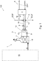
- Figure 1 is a schematic side view of an arrangement and method for recovering heat from flue gas of a boiler.
- the boiler 10 is a heating boiler that burns a combustion process fuel, such as biomass or fossil fuel.
- a combustion process fuel such as biomass or fossil fuel.
- the heat energy that is released in the combustion of the fuel is used to heat water that flows in a district heating network through a circulation arrangement of district heating water 6.
- the arrangement and the method may be applied in various types of combustion plants.
- the boiler may be, for instance, any type of chemical recovery boiler, fluidized bed boiler, pulverized coal fired boiler, gas fired boiler, pulverized pellet fired boiler, etc.
- the arrangement and the method may also be applied in combustion engines.
- the arrangement 100 comprises a flue gas cooling unit 1 that is configured to cool the flue gas G with a cooling liquid CL.
- the flue gas cooling unit 1 comprises a flue gas condenser, such as a flue gas scrubber 7 wherein the cooling liquid CL comprises scrubbing water.
- the flue gas cooling unit 1 comprises a tube heat exchanger, wherein the cooling takes place by a circulation liquid.
- the flue gas is passed through one or more heat exchange zone(s) or packing zone(s).
- the flue gas scrubber 7 shown in Figure 1 comprises one packing zone 18.
- the packing zone comprises a random packing bed acting as a heat and mass transfer surface.
- the flue gas G is cooled by spraying scrubbing water over the packing zone 18 and heat energy is released from the flue gas and recovered into the scrubbing water.
- the amount of heat energy that is released in the scrubbing process depends on the temperature of the scrubbing water, the dew point of the flue gas, as well as flue gas temperature and composition, available cooling liquid flow and temperature, such as temperature of district heating return water, connections and design of the complete system, and components and concepts thereof.
- the dew point depends on the moisture content of the flue gas. If the flue gas can be cooled under its dew point, the water vapor contained in the flue gas condenses and a large amount of heat energy is released and recovered into the scrubbing water.
- the arrangement 100 further comprises a heat pump 2 that is coupled to the flue gas cooling unit 1.
- the heat pump 2 is coupled to the flue gas cooling unit 1 by a heat exchanger 11.
- the flue gas cooling liquid CL is circulated by using one or more pump(s) 9 from the flue gas cooling unit 1 into the heat exchanger 11, and then back to the flue gas cooling unit 1.
- heat from the flue gas cooling liquid CL is transferred into a transfer liquid circulating in a transfer piping 19 between the heat exchanger 11 and the heat pump 2.
- the heat pump 2 is also connected to a circulation arrangement 6 of district heating system for receiving district heating fluid DHF, such as heating water of the district heating water system.
- the circulation arrangement 6 feeds heating water returning from a district heating network (not shown) used for heating e.g. residential and commercial objects in the heat pump 2.
- the heat pump 2 is connected to a circulation arrangement 8 of district cooling system for receiving district heating fluid DCF, such as cooling water of the district cooling system.
- the circulation arrangement 8 feeds cooling water returning from a district cooling network (not shown) used for cooling e.g. residential and commercial objects in the heat pump 2.
- the heat pump 2 is arranged to receive heat energy of the flue gas cooling liquid CL heated in the flue gas cooling unit 1, and heat energy of the district cooling fluid heated in the district cooling network.
- the received heat energy is used for raising temperature of the district heating fluid DHF.
- the heat pump 2 is an absorption heat pump (AHP).
- AHP absorption heat pump
- the concept of the AHP is known per se. It may comprise a generator, an evaporator, an absorber and a condenser. Two fluids that function as an absorption medium and a refrigerant are arranged in the AHP. The principle of operation of the AHP is based on absorption and evaporation of the refrigerant.
- the refrigerant is ammonia and the absorption medium is water (NH 3 /H 2 O).
- the generator of the heat pump is connected to a source of steam and/or hot water, such as the boiler 10 or another source, by a feed 16 of steam and/or hot water. Energy of the steam and/or hot water is used for running the AHP. Cooled steam and/or hot water may be returned to its source by a return 17 of feed.
- the evaporator of the heat pump is arranged for receiving heat from the flue gas cooling liquid CL, as described in this description. Heat energy received in the evaporator is transferred to the absorber of the heat pump by reactions of the second fluids. In the absorber, heat energy is transferred to the district heating fluid DHF that has cooled down in the circulation arrangement 6 of district heating system. The district heating fluid DHF is also directed through the condenser of the heat pump, in which the second fluid is adapted to condense from gas phase to liquid phase.
- the heat pump 2 is an electrical heat pump that comprises an electrical motor-driven compressor for driving the heat pump.
- the feed 16 of steam and/or hot water and the return 17 of feed are not necessary.
- a circulation arrangement 8 of district cooling system is connected to the heat pump 2 such that heat energy of district cooling fluid DCF coming from a district cooling network (not shown) and heated therein is transferred similarly as heat energy from the flue gas cooling liquid CL in the heat pump.
- the district cooling fluid DCF cools in the heat pump 2 and returned back in the circulation arrangement 8 of district cooling system.
- the circulation arrangement 8 of district cooling system is connected to the transfer piping 19, i.e. district cooling fluid DCF is fed together with transfer fluid in the heat pump 2, and cooled fluid is returned from the transfer piping 19 to the circulation arrangement 8 of district cooling system.
- the circulation arrangement 8 of district cooling system is connected via a heat exchanger to the heat pump 2.
- the circulation arrangement 6 of district heating system is separate from the circulation arrangement 8 of district cooling system.
- the circulation arrangement 8 of district cooling system is arranged to cool the same residential and commercial objects which the circulation arrangement of district heating system 6 is heating.
- the circulation arrangement 8 of district cooling system is connected to another residential and commercial objects as the circulation arrangement of district heating system 6.
- the circulation arrangement 6 of district heating system is connected to the heat pump 2 such that all the district heating fluid DHF is circulating through the heat pump 2.
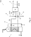
- Figure 2 is a schematic side view of another arrangement and method for recovering heat from flue gas of a boiler.
- the flue gas cooling unit 1 comprises a flue gas condenser, in which the flue gas G is cooled by flue gas cooling liquid CL by passing it in tubes arranged in the tube heat exchanger. Flue gas G is arranged to flow outside the tubes. Heat energy is transferred from flue gas G to the flue gas cooling liquid CL through the tube walls.
- the flue gas cooling liquid CL is fed in the heat pump 2 and circulating it back therefrom to the flue gas cooling unit 1.
- heat exchanger 11 is not always necessary.
- District cooling fluid DCF may be circulated through the heat pump 2 with the flue gas cooling liquid CL.
- Figure 3 is a schematic side view of a third arrangement and method for recovering heat from flue gas of a boiler.
- the flue gas is passed through one or more heat exchange zone(s) or packing zone(s).
- the flue gas scrubber 7 shown in Figure 1 comprises two packing zones 18a, 18b.
- the circuits of scrubbing water may be arranged differently, e.g. there may be less or more than three scrubbing water circuits, and/or less or more than two packing zones.
- flue gas cooling liquid CL that is fed - or at least heat energy of which is fed - in the heat pump 2 is arranged to circulate through at least the last of the heat exchange zones, that is the third heat exchange zone connected to the second packing zone 18b in the embodiment shown in Figure 3 .
- said flue gas cooling liquid CL is arranged to circulate also another heat exchange zone, such as the second heat exchange zone connected to the first packing zone 18a.
- the scrubbing water is circulated by using one or more pump(s) 9 from the flue gas scrubber 7 into a heat exchanger 11, and then back to the flue gas scrubber 7.
- the circulation arrangement 6 of district heating system comprises a by-pass piping 5 that is arranged for feeding only a part of the district heating fluid DHF coming from the circulation arrangement 6 of district heating system in the heat pump 2. Rest of said district heating fluid DHF is fed past the heat pump 2. In one embodiment, such as shown in Figure 3 , said rest of the district heating fluid DHF is fed to a heat exchanger 11 where it is arranged to receive heat energy from scrubbing water from the second heat exchange zone. In another embodiments, said rest of the district heating fluid DHF is fed for receiving heat energy from some other heat exchange zone.
- district heating fluid DHF fed in the heat pump 2 and past the pump may be controlled by e.g. valves 13.
- the amount of the district cooling fluid DCF mixed with flue gas cooling liquid is preferably controlled e.g. by valves as shown in Figures.
- Figure 4 is a schematic side view of a fourth arrangement and method for recovering heat from flue gas of a boiler.
- the arrangement comprises a combustion air humidifier 4 that is arranged for heating and moisturizing combustion air CA to be fed in the boiler 10.
- the combustion air humidifier 4 improves the heat recovery capacity by increasing the moisture content of the combustion air CA and thereby increasing the moisture content of the flue gas G.
- the combustion air humidifier 4 is connected to a flue gas cooling unit 1 by a feed piping 14 for receiving water therefrom and by a return channel leading the return water from the combustion air humidifier 4 back in the flue gas cooling unit 1.
- the combustion air humidifier 4 receives flue gas cooling liquid CL in higher temperature for heating and humidifying said combustion air CA and returns said flue gas cooling liquid CL back in lower temperature to the flue gas cooling unit 1 by a return piping 15.
- the return piping 15 is arranged in relation to the heat pump 2 so that the heat pump 2 receives heat energy from flue gas cooling liquid CL returning from the combustion air humidifier 4. Said heat energy is transferred to the district heating fluid DHF in the heat pump 2.
- the district cooling fluid DCF coming from the district cooling system 8 is arranged to be fed in the return piping 15 and along said piping to the heat pump 2.
- the district cooling system 8 is connected to the piping 12 that is arranged for returning cooled flue gas cooling liquid back to the flue gas cooling unit 1, and cooled district cooling fluid DCF is taken from said piping 12 and fed in the district cooling system 8 .
Landscapes
- Engineering & Computer Science (AREA)
- Mechanical Engineering (AREA)
- General Engineering & Computer Science (AREA)
- Physics & Mathematics (AREA)
- Thermal Sciences (AREA)
- Combustion & Propulsion (AREA)
- Chemical & Material Sciences (AREA)
- Air Supply (AREA)
- Treating Waste Gases (AREA)
- Chimneys And Flues (AREA)
- Steam Or Hot-Water Central Heating Systems (AREA)
- Other Air-Conditioning Systems (AREA)
- Central Heating Systems (AREA)
Abstract
Description
- The invention relates to a method for recovering heat from flue gas of a boiler.
- The invention further relates to an arrangement for recovering heat from flue gas of a boiler.
- It is known to use flue gas washing and condensing systems, such as condensers and scrubbers, in combustion plants for recovering heat from flue gas which is produced in the combustion of a fuel. In a flue gas scrubber, the flue gas is cooled by scrubbing water so that water vapour contained in the flue gas condenses and the released condensing heat may be utilized, for instance, in a district heating plant where the condensing heat is used to heat district heating water. The scrubbing water is circulated through a heat exchanger where heat energy is transferred into district heating water.
- It is also known to connect a heat pump between a supply channel feeding heated water in a district heating network and a return channel supplying district heating water returning from the district heating network back into the heat exchanger for heating. The heat pump is configured to heat the district heating water in the supply channel by using heat energy of water running in the return channel. An advantage is that cooler water is supplied in the heat exchanger and thus flue gases can be condensed to a lower temperature.
- Typical district heating power plants in the Nordics adjust their load depending on the outside temperature. Power plant load is decreased towards the summer season and when minimum loads are needed flue gas heat recovery plants are shut down or the effect has been minimized to reach low load for the plant. Thus, the overall energy efficiency of the plant is lowered in summer season.
- Viewed from a first aspect, there can be provided a method for recovering heat from flue gas of a boiler, the method comprising
- passing the flue gas of the boiler though a flue gas cooling unit,
- cooling the flue gas in the flue gas cooling unit, said cooling comprising transferring heat from the flue gas into a circulation of a flue gas cooling liquid,
- transferring heat energy of said flue gas cooling liquid heated in the flue gas cooling unit into a heat pump,
- arranging the heat pump for receiving heat energy also from a circulation arrangement of a district cooling system, wherein
- the heat pump is coupled to a circulation arrangement of a district heating system, wherein the method further comprises
- transferring in the heat pump heat energy received
- -- from said cooling liquid and
- -- from said circulation arrangement of district cooling system
- -- into said circulation arrangement of district heating system, for
- -- lowering the temperature of said flue gas cooling liquid and cooling fluid of said district cooling system, and
- -- raising the temperature of heating fluid of said district heating system.
- Thereby a method having high energy efficiency year-round may be achieved.
- Viewed from a further aspect, there can be provided an arrangement for recovering heat from flue gas of a boiler, the arrangement comprising a flue gas cooling unit, configured to cool the flue gas with a flue gas cooling liquid, a heat pump coupled to the flue gas cooling unit, to a circulation arrangement of a district cooling system, and to a circulation arrangement of a district heating system, the heat pump arranged to receive flue gas cooling liquid heated in said flue gas cooling unit, district cooling fluid from the circulation arrangement of a district cooling system, and district heating fluid from the circulation arrangement of a district heating system, the heat pump configured for receiving heat energy from the flue gas cooling liquid, for receiving heat energy from the district cooling fluid, and for raising temperature of the district heating fluid.
- Thereby an arrangement having high energy efficiency year-round may be achieved.
- The arrangement and the method are characterised by what is stated in the independent claims. Some other embodiments are characterised by what is stated in the other claims. Inventive embodiments are also disclosed in the specification and drawings of this patent application. The inventive content of the patent application may also be defined in other ways than defined in the following claims. The inventive content may also be formed of several separate inventions, especially if the invention is examined in the light of expressed or implicit sub-tasks or in view of obtained benefits or benefit groups. Some of the definitions contained in the following claims may then be unnecessary in view of the separate inventive ideas. Features of the different embodiments of the invention may, within the scope of the basic inventive idea, be applied to other embodiments.
- In one embodiment, the flue gas cooling unit comprises a flue gas scrubber.
- An advantage is that a high capacity of cooling may be achieved with an inexpensive way.
- In one embodiment, the flue gas cooling liquid is circulating through a plurality of heat exchange zones of the flue gas scrubber.
- An advantage is that capacity of cooling may further be achieved with an inexpensive way.
- In one embodiment, the flue gas cooling unit comprises a tube heat exchanger.
- An advantage is that the flue gas cooling unit has a low electricity consumption and a compact size that facilities designing the layout of the cooling unit.
- In one embodiment, the arrangement comprises a combustion air humidifier, and the method comprises feeding flue gas cooling liquid from the flue gas cooling unit into a combustion air humidifier, heating and moisturizing combustion air to be fed in the boiler by heat energy of said flue gas cooling liquid in said combustion air humidifier, and exiting flue gas cooling liquid cooled in the combustion air humidifier from said combustion air humidifier, the method further comprising transferring heat energy of flue gas cooling liquid exiting the combustion air humidifier into the heat pump.
- An advantage is that condensation of the water vapor and amount of heat energy released and recovered in the scrubbing water may be promoted.
- In one embodiment, the flue gas cooling liquid is fed in the heat pump and circulated back therefrom to the flue gas cooling unit.
- An advantage is that a very simple structure of arrangement may be achieved.
- In one embodiment, the flue gas cooling liquid is fed in a heat exchanger, and in the heat exchanger heat energy from the flue gas cooling liquid is transferred into a transfer liquid circulating between the heat exchanger and the heat pump.
- An advantage is that the heat pump is isolated from the flue gas cooling liquid that may be highly corrosive, and thus the heat pump may be manufactured from less expensive materials.
- In one embodiment, the heat pump is an electrical heat pump.
- An advantage is that the heat pump is simple and has compact outer dimensions.
- In one embodiment, the heat pump is an absorption heat pump (AHP).
- An advantage is that it is inexpensive to run the AHP since its electricity consumption is low and free heat energy is available from the boiler.
- In one embodiment, steam and/or hot water is fed in a generator of the AHP for driving the AHP.
- An advantage is that the heat pump may be driven with an inexpensive way.
- In one embodiment, all the district heating fluid coming from the circulation arrangement of district heating system is fed in the heat pump.
- An advantage is that capacity of transferring heat energy from the flue gas cooling unit and the district cooling system to the district heating system may be extended.
- In one embodiment, only a part of the district heating fluid coming from the circulation arrangement of district heating system is fed in the heat pump, and rest of said district heating fluid is fed past the heat pump.
- An advantage is that size of the heat pump may be kept reasonable even if the district heating system is large.
- Some embodiments illustrating the present disclosure are described in more detail in the attached drawings, in which
-
Figure 1 is a schematic side view of an arrangement and method for recovering heat from flue gas of a boiler, -
Figure 2 is a schematic side view of another arrangement and method for recovering heat from flue gas of a boiler, -
Figure 3 is a schematic side view of a third arrangement and method for recovering heat from flue gas of a boiler, and -
Figure 4 is a schematic side view of a fourth arrangement and method for recovering heat from flue gas of a boiler. - In the figures, some embodiments are shown simplified for the sake of clarity. Similar parts are marked with the same reference numbers in the figures.
-
Figure 1 is a schematic side view of an arrangement and method for recovering heat from flue gas of a boiler. - In the embodiment shown in
Figure 1 , theboiler 10 is a heating boiler that burns a combustion process fuel, such as biomass or fossil fuel. The heat energy that is released in the combustion of the fuel is used to heat water that flows in a district heating network through a circulation arrangement ofdistrict heating water 6. - However, it is to be noted, that the arrangement and the method may be applied in various types of combustion plants. The boiler may be, for instance, any type of chemical recovery boiler, fluidized bed boiler, pulverized coal fired boiler, gas fired boiler, pulverized pellet fired boiler, etc. The arrangement and the method may also be applied in combustion engines.
- The
arrangement 100 comprises a flue gas cooling unit 1 that is configured to cool the flue gas G with a cooling liquid CL. - In the embodiment shown in
Figure 1 , the flue gas cooling unit 1 comprises a flue gas condenser, such as aflue gas scrubber 7 wherein the cooling liquid CL comprises scrubbing water. - It is to be noted here, that in some embodiments the flue gas cooling unit 1 comprises a tube heat exchanger, wherein the cooling takes place by a circulation liquid.
- In the
flue gas scrubber 7, the flue gas is passed through one or more heat exchange zone(s) or packing zone(s). Theflue gas scrubber 7 shown inFigure 1 comprises onepacking zone 18. The packing zone comprises a random packing bed acting as a heat and mass transfer surface. - The flue gas G is cooled by spraying scrubbing water over the packing
zone 18 and heat energy is released from the flue gas and recovered into the scrubbing water. - The amount of heat energy that is released in the scrubbing process depends on the temperature of the scrubbing water, the dew point of the flue gas, as well as flue gas temperature and composition, available cooling liquid flow and temperature, such as temperature of district heating return water, connections and design of the complete system, and components and concepts thereof. The dew point depends on the moisture content of the flue gas. If the flue gas can be cooled under its dew point, the water vapor contained in the flue gas condenses and a large amount of heat energy is released and recovered into the scrubbing water.
- The
arrangement 100 further comprises aheat pump 2 that is coupled to the flue gas cooling unit 1. In one embodiment, such as shown inFigure 1 , theheat pump 2 is coupled to the flue gas cooling unit 1 by aheat exchanger 11. The flue gas cooling liquid CL is circulated by using one or more pump(s) 9 from the flue gas cooling unit 1 into theheat exchanger 11, and then back to the flue gas cooling unit 1. In theheat exchanger 11 heat from the flue gas cooling liquid CL is transferred into a transfer liquid circulating in a transfer piping 19 between theheat exchanger 11 and theheat pump 2. - In another embodiment, there is no
heat exchanger 11 but the flue gas cooling liquid CL (or at least part of it) is fed in theheat pump 2. - The
heat pump 2 is also connected to acirculation arrangement 6 of district heating system for receiving district heating fluid DHF, such as heating water of the district heating water system. Thecirculation arrangement 6 feeds heating water returning from a district heating network (not shown) used for heating e.g. residential and commercial objects in theheat pump 2. - Additionally, the
heat pump 2 is connected to acirculation arrangement 8 of district cooling system for receiving district heating fluid DCF, such as cooling water of the district cooling system. Thecirculation arrangement 8 feeds cooling water returning from a district cooling network (not shown) used for cooling e.g. residential and commercial objects in theheat pump 2. - Thus, the
heat pump 2 is arranged to receive heat energy of the flue gas cooling liquid CL heated in the flue gas cooling unit 1, and heat energy of the district cooling fluid heated in the district cooling network. The received heat energy is used for raising temperature of the district heating fluid DHF. - In one embodiment, such as shown in
Figure 1 , theheat pump 2 is an absorption heat pump (AHP). The concept of the AHP is known per se. It may comprise a generator, an evaporator, an absorber and a condenser. Two fluids that function as an absorption medium and a refrigerant are arranged in the AHP. The principle of operation of the AHP is based on absorption and evaporation of the refrigerant. In one embodiment, the refrigerant is ammonia and the absorption medium is water (NH3/H2O). - In one embodiment, the generator of the heat pump is connected to a source of steam and/or hot water, such as the
boiler 10 or another source, by afeed 16 of steam and/or hot water. Energy of the steam and/or hot water is used for running the AHP. Cooled steam and/or hot water may be returned to its source by areturn 17 of feed. - In one embodiment, the evaporator of the heat pump is arranged for receiving heat from the flue gas cooling liquid CL, as described in this description. Heat energy received in the evaporator is transferred to the absorber of the heat pump by reactions of the second fluids. In the absorber, heat energy is transferred to the district heating fluid DHF that has cooled down in the
circulation arrangement 6 of district heating system. The district heating fluid DHF is also directed through the condenser of the heat pump, in which the second fluid is adapted to condense from gas phase to liquid phase. - In another embodiment, the
heat pump 2 is an electrical heat pump that comprises an electrical motor-driven compressor for driving the heat pump. In this embodiment, thefeed 16 of steam and/or hot water and thereturn 17 of feed are not necessary. - A
circulation arrangement 8 of district cooling system is connected to theheat pump 2 such that heat energy of district cooling fluid DCF coming from a district cooling network (not shown) and heated therein is transferred similarly as heat energy from the flue gas cooling liquid CL in the heat pump. The district cooling fluid DCF cools in theheat pump 2 and returned back in thecirculation arrangement 8 of district cooling system. - In one embodiment, such as shown in
Figure 1 , thecirculation arrangement 8 of district cooling system is connected to the transfer piping 19, i.e. district cooling fluid DCF is fed together with transfer fluid in theheat pump 2, and cooled fluid is returned from the transfer piping 19 to thecirculation arrangement 8 of district cooling system. - In another embodiment, the
circulation arrangement 8 of district cooling system is connected via a heat exchanger to theheat pump 2. - In one embodiment, the
circulation arrangement 6 of district heating system is separate from thecirculation arrangement 8 of district cooling system. - the
circulation arrangement 8 of district cooling system is arranged to cool the same residential and commercial objects which the circulation arrangement ofdistrict heating system 6 is heating. In another embodiment, thecirculation arrangement 8 of district cooling system is connected to another residential and commercial objects as the circulation arrangement ofdistrict heating system 6. - In one embodiment, such as shown in
Figure 1 , thecirculation arrangement 6 of district heating system is connected to theheat pump 2 such that all the district heating fluid DHF is circulating through theheat pump 2. -
Figure 2 is a schematic side view of another arrangement and method for recovering heat from flue gas of a boiler. - In one embodiment, such as shown in
Figure 2 , the flue gas cooling unit 1 comprises a flue gas condenser, in which the flue gas G is cooled by flue gas cooling liquid CL by passing it in tubes arranged in the tube heat exchanger. Flue gas G is arranged to flow outside the tubes. Heat energy is transferred from flue gas G to the flue gas cooling liquid CL through the tube walls. - In one embodiment, the flue gas cooling liquid CL is fed in the
heat pump 2 and circulating it back therefrom to the flue gas cooling unit 1. In other words,heat exchanger 11 is not always necessary. District cooling fluid DCF may be circulated through theheat pump 2 with the flue gas cooling liquid CL. -
Figure 3 is a schematic side view of a third arrangement and method for recovering heat from flue gas of a boiler. - In the
flue gas scrubber 7, the flue gas is passed through one or more heat exchange zone(s) or packing zone(s). Theflue gas scrubber 7 shown inFigure 1 comprises twopacking zones - In the shown embodiment, there are three scrubbing water circuits in the
scrubber 7. First of the circuits is connected to a first cooling zone arranged under thefirst packing zone 18a, second circuit to thefirst packing zone 18a, and third circuit to thesecond packing zone 18b. However, in some embodiments the circuits of scrubbing water may be arranged differently, e.g. there may be less or more than three scrubbing water circuits, and/or less or more than two packing zones. - In one embodiment, flue gas cooling liquid CL that is fed - or at least heat energy of which is fed - in the
heat pump 2 is arranged to circulate through at least the last of the heat exchange zones, that is the third heat exchange zone connected to thesecond packing zone 18b in the embodiment shown inFigure 3 . In another embodiment, said flue gas cooling liquid CL is arranged to circulate also another heat exchange zone, such as the second heat exchange zone connected to thefirst packing zone 18a. - The scrubbing water is circulated by using one or more pump(s) 9 from the
flue gas scrubber 7 into aheat exchanger 11, and then back to theflue gas scrubber 7. - In one embodiment, the
circulation arrangement 6 of district heating system comprises a by-pass piping 5 that is arranged for feeding only a part of the district heating fluid DHF coming from thecirculation arrangement 6 of district heating system in theheat pump 2. Rest of said district heating fluid DHF is fed past theheat pump 2. In one embodiment, such as shown inFigure 3 , said rest of the district heating fluid DHF is fed to aheat exchanger 11 where it is arranged to receive heat energy from scrubbing water from the second heat exchange zone. In another embodiments, said rest of the district heating fluid DHF is fed for receiving heat energy from some other heat exchange zone. - The relation of district heating fluid DHF fed in the
heat pump 2 and past the pump may be controlled bye.g. valves 13. - The amount of the district cooling fluid DCF mixed with flue gas cooling liquid is preferably controlled e.g. by valves as shown in Figures.
-
Figure 4 is a schematic side view of a fourth arrangement and method for recovering heat from flue gas of a boiler. - In one embodiment, the arrangement comprises a combustion air humidifier 4 that is arranged for heating and moisturizing combustion air CA to be fed in the
boiler 10. - The combustion air humidifier 4 improves the heat recovery capacity by increasing the moisture content of the combustion air CA and thereby increasing the moisture content of the flue gas G.
- The combustion air humidifier 4 is connected to a flue gas cooling unit 1 by a feed piping 14 for receiving water therefrom and by a return channel leading the return water from the combustion air humidifier 4 back in the flue gas cooling unit 1.
- The combustion air humidifier 4 receives flue gas cooling liquid CL in higher temperature for heating and humidifying said combustion air CA and returns said flue gas cooling liquid CL back in lower temperature to the flue gas cooling unit 1 by a return piping 15. The return piping 15 is arranged in relation to the
heat pump 2 so that theheat pump 2 receives heat energy from flue gas cooling liquid CL returning from the combustion air humidifier 4. Said heat energy is transferred to the district heating fluid DHF in theheat pump 2. - In one embodiment, the district cooling fluid DCF coming from the
district cooling system 8 is arranged to be fed in the return piping 15 and along said piping to theheat pump 2. - In one embodiment, the
district cooling system 8 is connected to the piping 12 that is arranged for returning cooled flue gas cooling liquid back to the flue gas cooling unit 1, and cooled district cooling fluid DCF is taken from saidpiping 12 and fed in thedistrict cooling system 8 . - The invention is not limited solely to the embodiments described above, but instead many variations are possible within the scope of the inventive concept defined by the claims below. Within the scope of the inventive concept the attributes of different embodiments and applications can be used in conjunction with or replace the attributes of another embodiment or application.
- The drawings and the related description are only intended to illustrate the idea of the invention. The invention may vary in detail within the scope of the inventive idea defined in the following claims.
-
- 1
- flue gas cooling unit
- 2
- heat pump
- 3
- circulation of flue gas cooling liquid
- 4
- combustion air humidifier
- 5
- by-pass piping of district HEATING system
- 6
- circulation arrangement of district heating system
- 7
- flue gas scrubber
- 8
- circulation arrangement of district cooling system
- 9
- pump
- 10
- boiler
- 11
- heat exchanger
- 12
- piping for flue gas cooling liquid
- 13
- valve
- 14
- feed piping
- 15
- return piping
- 16
- feed of steam and/or hot water
- 17
- return of feed
- 18
- packing zone
- 19
- transfer piping
- 100
- arrangement
- A
- air
- CA
- combustion air
- CL
- flue gas cooling liquid
- DHF
- district heating fluid
- DCF
- district cooling fluid
- G
- flue gas
Claims (17)
- A method for recovering heat from flue gas of a boiler (10), the method comprising- passing the flue gas (G) of the boiler though a flue gas cooling unit (1),- cooling the flue gas (G) in the flue gas cooling unit (1), said cooling comprising transferring heat from the flue gas (G) into a circulation (3) of a flue gas cooling liquid (CL),- transferring heat energy of said flue gas cooling liquid (CL) heated in the flue gas cooling unit (1) into a heat pump (2),- arranging the heat pump (2) for receiving heat energy also from a circulation arrangement (8) of a district cooling system, wherein- the heat pump (2) is coupled to a circulation arrangement (6) of a district heating system, wherein the method further comprises- transferring in the heat pump (2) heat energy (H) received-- from said cooling liquid (CL) and-- from said circulation arrangement (8) of district cooling system-- into said circulation arrangement (6) of district heating system, for-- lowering the temperature of said flue gas cooling liquid (CL) and cooling fluid of said district cooling system, and-- raising the temperature of heating fluid of said district heating system.
- The method as claimed in claim 1, comprising- cooling the flue gas (G) in a flue gas scrubber by said flue gas cooling liquid (CL).
- The method as claimed in claim 1, comprising cooling the flue gas (G) in a tube heat exchanger by said flue gas cooling liquid (CL).
- The method as claimed in any of the preceding claims, comprising- feeding flue gas cooling liquid (CL) from the flue gas cooling unit (1) into a combustion air humidifier (4),- heating and moisturizing combustion air to be fed in the boiler by heat energy of said flue gas cooling liquid (CL) in said combustion air humidifier (4), and- exiting flue gas cooling liquid (CL) cooled in the combustion air humidifier (4) from said combustion air humidifier (4), the method further comprising- transferring heat energy of flue gas cooling liquid (CL) exiting the combustion air humidifier (4) into the heat pump (2).
- The method as claimed in any of the preceding claims, comprising- feeding the flue gas cooling liquid (CL) in the heat pump and circulating it back therefrom to the flue gas cooling unit (1).
- The method as claimed in any of claims 1 - 4, comprising- feeding the flue gas cooling liquid (CL) in a heat exchanger (11), and in the heat exchanger (11),- transferring heat from the flue gas cooling liquid (CL) into a transfer liquid circulating between the heat exchanger (11) and the heat pump (2).
- The method as claimed in any of claims 1 - 6, wherein- the heat pump (2) is an absorption heat pump (AHP).
- The method as claimed in claim 7, comprising- feeding steam and/or hot water in a generator of the AHP for driving the AHP.
- The method as claimed in any of the preceding claims, comprising- feeding all the district heating fluid (DHF) coming from the circulation arrangement (6) of district heating system in the heat pump (2).
- The method as claimed in any of claims 1 - 9, comprising- feeding only a part of the district heating fluid (DHF) coming from the circulation arrangement (6) of district heating system in the heat pump (2), and- feeding rest of said district heating fluid (DHF) past the heat pump (2).
- An arrangement for recovering heat from flue gas of a boiler (10), the arrangement (100) comprising- a flue gas cooling unit (1), configured to cool the flue gas (G) with a flue gas cooling liquid (CL),- a heat pump (2) coupled to- the flue gas cooling unit (1),- a circulation arrangement (8) of a district cooling system, and- a circulation arrangement (6) of a district heating system,- the heat pump (2) arranged to receive- flue gas cooling liquid (CL) heated in said flue gas cooling unit (1),- district cooling fluid from the circulation arrangement (8) of a district cooling system,- district heating fluid from the circulation arrangement (6) of a district heating system,- the heat pump (2) configured for- receiving heat energy from the flue gas cooling liquid (CL),- receiving heat energy from the district cooling fluid, and- raising temperature of the district heating fluid.
- The arrangement as claimed in claim 11, wherein the flue gas cooling unit (1) comprises a flue gas scrubber or a flue gas condenser.
- The arrangement as claimed in any of claims 11 - 12, comprising- a combustion air humidifier (4) arranged for heating and moisturizing combustion air to be fed in the boiler, wherein- the combustion air humidifier (4) is connected to the the flue gas cooling unit (1) by a feed piping (14) for receiving flue gas cooling liquid (CL) in higher temperature for heating said combustion air,- the combustion air humidifier (4) being arranged for returning said flue gas cooling liquid (CL) in lower temperature back to the flue gas cooling unit (1) by a return piping (15), wherein- the heat pump (2) is arranged in relation to the return piping for receiving heat energy therefrom and transfer said heat energy to the district heating fluid.
- The arrangement as claimed in any of claims 11 - 13, comprising a heat exchanger (11) arranged for- receiving the flue gas cooling liquid (CL) from the flue gas cooling unit (1) and/or the combustion air humidifier (4), and- transferring heat from the flue gas cooling liquid (CL) into a transfer liquid arranged to circulate between the heat exchanger (11) and the heat pump (2).
- The arrangement as claimed in any of claims 11 - 14, wherein the heat pump (2) is an absorption heat pump (AHP).
- the arrangement as claimed in any of claims 11 - 15, wherein the circulation arrangement (6) of district heating system is connected to the heat pump (2) for circulating all the district heating fluid (DHF) through the heat pump (2).
- The arrangement as claimed in any of claims 11 - 15, wherein the circulation arrangement (6) of district heating system comprises a by-pass piping (5) arranged for feeding only a part of the district heating fluid (DHF) coming from the circulation arrangement (6) of district heating system in the heat pump (2).
Applications Claiming Priority (1)
| Application Number | Priority Date | Filing Date | Title |
|---|---|---|---|
| FI20206158A FI129538B (en) | 2020-11-16 | 2020-11-16 | Method and arrangement |
Publications (2)
| Publication Number | Publication Date |
|---|---|
| EP4001598A1 true EP4001598A1 (en) | 2022-05-25 |
| EP4001598B1 EP4001598B1 (en) | 2024-07-17 |
Family
ID=78827972
Family Applications (1)
| Application Number | Title | Priority Date | Filing Date |
|---|---|---|---|
| EP21208246.5A Active EP4001598B1 (en) | 2020-11-16 | 2021-11-15 | Method and arrangement |
Country Status (7)
| Country | Link |
|---|---|
| US (1) | US20220154974A1 (en) |
| EP (1) | EP4001598B1 (en) |
| JP (1) | JP2022079429A (en) |
| CN (1) | CN114508774A (en) |
| CA (1) | CA3136958A1 (en) |
| DK (1) | DK4001598T3 (en) |
| FI (1) | FI129538B (en) |
Cited By (1)
| Publication number | Priority date | Publication date | Assignee | Title |
|---|---|---|---|---|
| WO2026082941A1 (en) * | 2024-10-18 | 2026-04-23 | Dall Energy Aps | Method and system for flexible heating plant by integration of biomass heating system and electrical heat pump system |
Families Citing this family (3)
| Publication number | Priority date | Publication date | Assignee | Title |
|---|---|---|---|---|
| EP4286770A1 (en) * | 2022-06-03 | 2023-12-06 | Siemens Energy Global GmbH & Co. KG | Producing heat in low carbon energy systems |
| FI131955B1 (en) * | 2023-12-29 | 2026-03-11 | Aliceco Ip Oy | System and method for efficient district heating and flue gas cleaning |
| US12348185B1 (en) * | 2024-07-05 | 2025-07-01 | Schlumberger Technology Corporation | Integrated hybrid solar energy plant and district heating and cooling network |
Citations (6)
| Publication number | Priority date | Publication date | Assignee | Title |
|---|---|---|---|---|
| US4660511A (en) * | 1986-04-01 | 1987-04-28 | Anderson J Hilbert | Flue gas heat recovery system |
| DE3607356A1 (en) * | 1986-03-06 | 1987-09-10 | Hubert Nuebel | Heating device with smoke-gas washer |
| EP1816397A1 (en) * | 2006-02-02 | 2007-08-08 | Fritz Egger GmbH & Co | Method and device for heat recovery, from humid exhaust air |
| FR2979974A3 (en) * | 2011-09-14 | 2013-03-15 | Heloro S R O | METHOD AND SYSTEM FOR TREATING COMBUSTION GAS FROM A HEAT SOURCE |
| US20180245800A1 (en) * | 2015-09-11 | 2018-08-30 | University of Maribor | Method and apparatus for utilization of hot water plant waste heat recovery by incorporated high temperature water source heat pump |
| EP3708915A1 (en) * | 2019-03-11 | 2020-09-16 | HögforsGST Oy | District-heating system and method for increasing consumer power |
Family Cites Families (2)
| Publication number | Priority date | Publication date | Assignee | Title |
|---|---|---|---|---|
| EP2459755B1 (en) * | 2009-07-31 | 2014-09-03 | HYL Technologies, S.A. de C.V. | Method for producing direct reduced iron with limited co2 emissions and apparatus therefor |
| CN104534539A (en) * | 2015-01-08 | 2015-04-22 | 清华大学 | Gas steam combined cycle central heating device and heating method |
-
2020
- 2020-11-16 FI FI20206158A patent/FI129538B/en active IP Right Grant
-
2021
- 2021-10-29 CA CA3136958A patent/CA3136958A1/en active Pending
- 2021-11-04 JP JP2021180609A patent/JP2022079429A/en active Pending
- 2021-11-08 CN CN202111312240.1A patent/CN114508774A/en active Pending
- 2021-11-15 US US17/526,366 patent/US20220154974A1/en not_active Abandoned
- 2021-11-15 DK DK21208246.5T patent/DK4001598T3/en active
- 2021-11-15 EP EP21208246.5A patent/EP4001598B1/en active Active
Patent Citations (6)
| Publication number | Priority date | Publication date | Assignee | Title |
|---|---|---|---|---|
| DE3607356A1 (en) * | 1986-03-06 | 1987-09-10 | Hubert Nuebel | Heating device with smoke-gas washer |
| US4660511A (en) * | 1986-04-01 | 1987-04-28 | Anderson J Hilbert | Flue gas heat recovery system |
| EP1816397A1 (en) * | 2006-02-02 | 2007-08-08 | Fritz Egger GmbH & Co | Method and device for heat recovery, from humid exhaust air |
| FR2979974A3 (en) * | 2011-09-14 | 2013-03-15 | Heloro S R O | METHOD AND SYSTEM FOR TREATING COMBUSTION GAS FROM A HEAT SOURCE |
| US20180245800A1 (en) * | 2015-09-11 | 2018-08-30 | University of Maribor | Method and apparatus for utilization of hot water plant waste heat recovery by incorporated high temperature water source heat pump |
| EP3708915A1 (en) * | 2019-03-11 | 2020-09-16 | HögforsGST Oy | District-heating system and method for increasing consumer power |
Cited By (1)
| Publication number | Priority date | Publication date | Assignee | Title |
|---|---|---|---|---|
| WO2026082941A1 (en) * | 2024-10-18 | 2026-04-23 | Dall Energy Aps | Method and system for flexible heating plant by integration of biomass heating system and electrical heat pump system |
Also Published As
| Publication number | Publication date |
|---|---|
| US20220154974A1 (en) | 2022-05-19 |
| DK4001598T3 (en) | 2024-10-07 |
| FI129538B (en) | 2022-04-14 |
| FI20206158A1 (en) | 2022-04-14 |
| EP4001598B1 (en) | 2024-07-17 |
| JP2022079429A (en) | 2022-05-26 |
| CN114508774A (en) | 2022-05-17 |
| CA3136958A1 (en) | 2022-05-16 |
Similar Documents
| Publication | Publication Date | Title |
|---|---|---|
| EP4001598B1 (en) | Method and arrangement | |
| EP3633272B1 (en) | Method for recovering heat from flue gas of boiler, and arrangement | |
| US9057288B2 (en) | Process utilizing high performance air-cooled combined cycle power plant with dual working fluid bottoming cycle and integrated capacity control | |
| US10221726B2 (en) | Condensing heat recovery steam generator | |
| US7690201B2 (en) | Method of efficiency and emissions performance improvement for the simple steam cycle | |
| EP2949997B1 (en) | Method and arrangement for transferring heat from flue gas into fluid | |
| CN103574630A (en) | Method for improving temperature of smoke discharged by chimney of thermal power plant, smoke heating system and thermal power generation unit | |
| US20120167838A1 (en) | Heat Recovery Module | |
| JPS597862A (en) | Absorption type heat pump system | |
| CN104501608B (en) | The device and method of the overheated heating furnace saturated vapor of a kind of sintering large flue waste heat | |
| US20240310035A1 (en) | Process and Steam Generating Device for Generating Process Steam | |
| CN112097287B (en) | Boiler energy-saving and flue gas whitening system, process and application | |
| CN113028383A (en) | Flue gas waste heat cascade utilization system of coal-fired power plant boiler | |
| CN117516243A (en) | Boiler flue gas waste heat deep recovery energy saving system | |
| RU2662259C2 (en) | Thermal power station with orc-module circuit and with heat pump and method of its work | |
| CN110578931B (en) | System and method for adjusting secondary air temperature by utilizing condensation water to improve heater | |
| EP3184757A1 (en) | Condensing heat recovery steam generator | |
| PL213507B1 (en) | Method used in the power plant and the power plant | |
| US9435534B2 (en) | Energy-recovery system for a production plant | |
| CN221464409U (en) | Deep recovery energy-saving system for waste heat of boiler flue gas | |
| PL246389B1 (en) | Method and system for recovering waste heat from fuel combustion | |
| SU1733841A1 (en) | Boiler | |
| EP3394402B1 (en) | Condensing heat recovery steam generator | |
| RU2232277C2 (en) | District-heating steam-power plant |
Legal Events
| Date | Code | Title | Description |
|---|---|---|---|
| PUAI | Public reference made under article 153(3) epc to a published international application that has entered the european phase |
Free format text: ORIGINAL CODE: 0009012 |
|
| STAA | Information on the status of an ep patent application or granted ep patent |
Free format text: STATUS: THE APPLICATION HAS BEEN PUBLISHED |
|
| AK | Designated contracting states |
Kind code of ref document: A1 Designated state(s): AL AT BE BG CH CY CZ DE DK EE ES FI FR GB GR HR HU IE IS IT LI LT LU LV MC MK MT NL NO PL PT RO RS SE SI SK SM TR |
|
| RIN1 | Information on inventor provided before grant (corrected) |
Inventor name: HANNULA, OLLI Inventor name: HANNULA, VILLE Inventor name: HANNULA, KALLE Inventor name: PAAVOLA, MIKKO |
|
| STAA | Information on the status of an ep patent application or granted ep patent |
Free format text: STATUS: REQUEST FOR EXAMINATION WAS MADE |
|
| 17P | Request for examination filed |
Effective date: 20221007 |
|
| RBV | Designated contracting states (corrected) |
Designated state(s): AL AT BE BG CH CY CZ DE DK EE ES FI FR GB GR HR HU IE IS IT LI LT LU LV MC MK MT NL NO PL PT RO RS SE SI SK SM TR |
|
| STAA | Information on the status of an ep patent application or granted ep patent |
Free format text: STATUS: EXAMINATION IS IN PROGRESS |
|
| 17Q | First examination report despatched |
Effective date: 20230704 |
|
| RIC1 | Information provided on ipc code assigned before grant |
Ipc: F25B 15/04 20060101ALI20240223BHEP Ipc: F23J 15/00 20060101ALI20240223BHEP Ipc: F23J 15/06 20060101ALI20240223BHEP Ipc: F23J 15/04 20060101ALI20240223BHEP Ipc: F24D 15/04 20060101ALI20240223BHEP Ipc: F24D 10/00 20220101ALI20240223BHEP Ipc: F25B 29/00 20060101ALI20240223BHEP Ipc: F22B 37/00 20060101ALI20240223BHEP Ipc: F01K 17/00 20060101AFI20240223BHEP |
|
| GRAP | Despatch of communication of intention to grant a patent |
Free format text: ORIGINAL CODE: EPIDOSNIGR1 |
|
| STAA | Information on the status of an ep patent application or granted ep patent |
Free format text: STATUS: GRANT OF PATENT IS INTENDED |
|
| INTG | Intention to grant announced |
Effective date: 20240411 |
|
| RIN1 | Information on inventor provided before grant (corrected) |
Inventor name: HANNULA, OLLI Inventor name: HANNULA, VILLE Inventor name: HANNULA, KALLE Inventor name: PAAVOLA, MIKKO |
|
| GRAS | Grant fee paid |
Free format text: ORIGINAL CODE: EPIDOSNIGR3 |
|
| GRAA | (expected) grant |
Free format text: ORIGINAL CODE: 0009210 |
|
| STAA | Information on the status of an ep patent application or granted ep patent |
Free format text: STATUS: THE PATENT HAS BEEN GRANTED |
|
| AK | Designated contracting states |
Kind code of ref document: B1 Designated state(s): AL AT BE BG CH CY CZ DE DK EE ES FI FR GB GR HR HU IE IS IT LI LT LU LV MC MK MT NL NO PL PT RO RS SE SI SK SM TR |
|
| REG | Reference to a national code |
Ref country code: CH Ref legal event code: EP |
|
| REG | Reference to a national code |
Ref country code: DE Ref legal event code: R096 Ref document number: 602021015762 Country of ref document: DE |
|
| REG | Reference to a national code |
Ref country code: IE Ref legal event code: FG4D |
|
| REG | Reference to a national code |
Ref country code: DK Ref legal event code: T3 Effective date: 20241004 |
|
| REG | Reference to a national code |
Ref country code: SE Ref legal event code: TRGR |
|
| REG | Reference to a national code |
Ref country code: LT Ref legal event code: MG9D |
|
| REG | Reference to a national code |
Ref country code: NL Ref legal event code: MP Effective date: 20240717 |
|
| PG25 | Lapsed in a contracting state [announced via postgrant information from national office to epo] |
Ref country code: PT Free format text: LAPSE BECAUSE OF FAILURE TO SUBMIT A TRANSLATION OF THE DESCRIPTION OR TO PAY THE FEE WITHIN THE PRESCRIBED TIME-LIMIT Effective date: 20241118 |
|
| REG | Reference to a national code |
Ref country code: AT Ref legal event code: UEP Ref document number: 1704337 Country of ref document: AT Kind code of ref document: T Effective date: 20240717 |
|
| PG25 | Lapsed in a contracting state [announced via postgrant information from national office to epo] |
Ref country code: NL Free format text: LAPSE BECAUSE OF FAILURE TO SUBMIT A TRANSLATION OF THE DESCRIPTION OR TO PAY THE FEE WITHIN THE PRESCRIBED TIME-LIMIT Effective date: 20240717 |
|
| PG25 | Lapsed in a contracting state [announced via postgrant information from national office to epo] |
Ref country code: PT Free format text: LAPSE BECAUSE OF FAILURE TO SUBMIT A TRANSLATION OF THE DESCRIPTION OR TO PAY THE FEE WITHIN THE PRESCRIBED TIME-LIMIT Effective date: 20241118 Ref country code: NL Free format text: LAPSE BECAUSE OF FAILURE TO SUBMIT A TRANSLATION OF THE DESCRIPTION OR TO PAY THE FEE WITHIN THE PRESCRIBED TIME-LIMIT Effective date: 20240717 |
|
| PG25 | Lapsed in a contracting state [announced via postgrant information from national office to epo] |
Ref country code: NO Free format text: LAPSE BECAUSE OF FAILURE TO SUBMIT A TRANSLATION OF THE DESCRIPTION OR TO PAY THE FEE WITHIN THE PRESCRIBED TIME-LIMIT Effective date: 20241017 |
|
| PG25 | Lapsed in a contracting state [announced via postgrant information from national office to epo] |
Ref country code: GR Free format text: LAPSE BECAUSE OF FAILURE TO SUBMIT A TRANSLATION OF THE DESCRIPTION OR TO PAY THE FEE WITHIN THE PRESCRIBED TIME-LIMIT Effective date: 20241018 Ref country code: PL Free format text: LAPSE BECAUSE OF FAILURE TO SUBMIT A TRANSLATION OF THE DESCRIPTION OR TO PAY THE FEE WITHIN THE PRESCRIBED TIME-LIMIT Effective date: 20240717 Ref country code: FI Free format text: LAPSE BECAUSE OF FAILURE TO SUBMIT A TRANSLATION OF THE DESCRIPTION OR TO PAY THE FEE WITHIN THE PRESCRIBED TIME-LIMIT Effective date: 20240717 |
|
| PG25 | Lapsed in a contracting state [announced via postgrant information from national office to epo] |
Ref country code: BG Free format text: LAPSE BECAUSE OF FAILURE TO SUBMIT A TRANSLATION OF THE DESCRIPTION OR TO PAY THE FEE WITHIN THE PRESCRIBED TIME-LIMIT Effective date: 20240717 |
|
| PG25 | Lapsed in a contracting state [announced via postgrant information from national office to epo] |
Ref country code: LV Free format text: LAPSE BECAUSE OF FAILURE TO SUBMIT A TRANSLATION OF THE DESCRIPTION OR TO PAY THE FEE WITHIN THE PRESCRIBED TIME-LIMIT Effective date: 20240717 |
|
| PG25 | Lapsed in a contracting state [announced via postgrant information from national office to epo] |
Ref country code: IS Free format text: LAPSE BECAUSE OF FAILURE TO SUBMIT A TRANSLATION OF THE DESCRIPTION OR TO PAY THE FEE WITHIN THE PRESCRIBED TIME-LIMIT Effective date: 20241117 |
|
| PG25 | Lapsed in a contracting state [announced via postgrant information from national office to epo] |
Ref country code: HR Free format text: LAPSE BECAUSE OF FAILURE TO SUBMIT A TRANSLATION OF THE DESCRIPTION OR TO PAY THE FEE WITHIN THE PRESCRIBED TIME-LIMIT Effective date: 20240717 |
|
| PG25 | Lapsed in a contracting state [announced via postgrant information from national office to epo] |
Ref country code: ES Free format text: LAPSE BECAUSE OF FAILURE TO SUBMIT A TRANSLATION OF THE DESCRIPTION OR TO PAY THE FEE WITHIN THE PRESCRIBED TIME-LIMIT Effective date: 20240717 Ref country code: RS Free format text: LAPSE BECAUSE OF FAILURE TO SUBMIT A TRANSLATION OF THE DESCRIPTION OR TO PAY THE FEE WITHIN THE PRESCRIBED TIME-LIMIT Effective date: 20241017 |
|
| PG25 | Lapsed in a contracting state [announced via postgrant information from national office to epo] |
Ref country code: RS Free format text: LAPSE BECAUSE OF FAILURE TO SUBMIT A TRANSLATION OF THE DESCRIPTION OR TO PAY THE FEE WITHIN THE PRESCRIBED TIME-LIMIT Effective date: 20241017 Ref country code: PL Free format text: LAPSE BECAUSE OF FAILURE TO SUBMIT A TRANSLATION OF THE DESCRIPTION OR TO PAY THE FEE WITHIN THE PRESCRIBED TIME-LIMIT Effective date: 20240717 Ref country code: NO Free format text: LAPSE BECAUSE OF FAILURE TO SUBMIT A TRANSLATION OF THE DESCRIPTION OR TO PAY THE FEE WITHIN THE PRESCRIBED TIME-LIMIT Effective date: 20241017 Ref country code: LV Free format text: LAPSE BECAUSE OF FAILURE TO SUBMIT A TRANSLATION OF THE DESCRIPTION OR TO PAY THE FEE WITHIN THE PRESCRIBED TIME-LIMIT Effective date: 20240717 Ref country code: IS Free format text: LAPSE BECAUSE OF FAILURE TO SUBMIT A TRANSLATION OF THE DESCRIPTION OR TO PAY THE FEE WITHIN THE PRESCRIBED TIME-LIMIT Effective date: 20241117 Ref country code: HR Free format text: LAPSE BECAUSE OF FAILURE TO SUBMIT A TRANSLATION OF THE DESCRIPTION OR TO PAY THE FEE WITHIN THE PRESCRIBED TIME-LIMIT Effective date: 20240717 Ref country code: GR Free format text: LAPSE BECAUSE OF FAILURE TO SUBMIT A TRANSLATION OF THE DESCRIPTION OR TO PAY THE FEE WITHIN THE PRESCRIBED TIME-LIMIT Effective date: 20241018 Ref country code: FI Free format text: LAPSE BECAUSE OF FAILURE TO SUBMIT A TRANSLATION OF THE DESCRIPTION OR TO PAY THE FEE WITHIN THE PRESCRIBED TIME-LIMIT Effective date: 20240717 Ref country code: ES Free format text: LAPSE BECAUSE OF FAILURE TO SUBMIT A TRANSLATION OF THE DESCRIPTION OR TO PAY THE FEE WITHIN THE PRESCRIBED TIME-LIMIT Effective date: 20240717 Ref country code: BG Free format text: LAPSE BECAUSE OF FAILURE TO SUBMIT A TRANSLATION OF THE DESCRIPTION OR TO PAY THE FEE WITHIN THE PRESCRIBED TIME-LIMIT Effective date: 20240717 |
|
| PG25 | Lapsed in a contracting state [announced via postgrant information from national office to epo] |
Ref country code: RO Free format text: LAPSE BECAUSE OF FAILURE TO SUBMIT A TRANSLATION OF THE DESCRIPTION OR TO PAY THE FEE WITHIN THE PRESCRIBED TIME-LIMIT Effective date: 20240717 Ref country code: SM Free format text: LAPSE BECAUSE OF FAILURE TO SUBMIT A TRANSLATION OF THE DESCRIPTION OR TO PAY THE FEE WITHIN THE PRESCRIBED TIME-LIMIT Effective date: 20240717 |
|
| REG | Reference to a national code |
Ref country code: DE Ref legal event code: R097 Ref document number: 602021015762 Country of ref document: DE |
|
| PG25 | Lapsed in a contracting state [announced via postgrant information from national office to epo] |
Ref country code: EE Free format text: LAPSE BECAUSE OF FAILURE TO SUBMIT A TRANSLATION OF THE DESCRIPTION OR TO PAY THE FEE WITHIN THE PRESCRIBED TIME-LIMIT Effective date: 20240717 |
|
| PG25 | Lapsed in a contracting state [announced via postgrant information from national office to epo] |
Ref country code: CZ Free format text: LAPSE BECAUSE OF FAILURE TO SUBMIT A TRANSLATION OF THE DESCRIPTION OR TO PAY THE FEE WITHIN THE PRESCRIBED TIME-LIMIT Effective date: 20240717 |
|
| PG25 | Lapsed in a contracting state [announced via postgrant information from national office to epo] |
Ref country code: SK Free format text: LAPSE BECAUSE OF FAILURE TO SUBMIT A TRANSLATION OF THE DESCRIPTION OR TO PAY THE FEE WITHIN THE PRESCRIBED TIME-LIMIT Effective date: 20240717 |
|
| PLBE | No opposition filed within time limit |
Free format text: ORIGINAL CODE: 0009261 |
|
| STAA | Information on the status of an ep patent application or granted ep patent |
Free format text: STATUS: NO OPPOSITION FILED WITHIN TIME LIMIT |
|
| 26N | No opposition filed |
Effective date: 20250422 |
|
| REG | Reference to a national code |
Ref country code: CH Ref legal event code: PL |
|
| PG25 | Lapsed in a contracting state [announced via postgrant information from national office to epo] |
Ref country code: MC Free format text: LAPSE BECAUSE OF FAILURE TO SUBMIT A TRANSLATION OF THE DESCRIPTION OR TO PAY THE FEE WITHIN THE PRESCRIBED TIME-LIMIT Effective date: 20240717 |
|
| PG25 | Lapsed in a contracting state [announced via postgrant information from national office to epo] |
Ref country code: LU Free format text: LAPSE BECAUSE OF NON-PAYMENT OF DUE FEES Effective date: 20241115 |
|
| REG | Reference to a national code |
Ref country code: CH Ref legal event code: PL |
|
| PG25 | Lapsed in a contracting state [announced via postgrant information from national office to epo] |
Ref country code: CH Free format text: LAPSE BECAUSE OF NON-PAYMENT OF DUE FEES Effective date: 20241130 |
|
| REG | Reference to a national code |
Ref country code: BE Ref legal event code: MM Effective date: 20241130 |
|
| PG25 | Lapsed in a contracting state [announced via postgrant information from national office to epo] |
Ref country code: BE Free format text: LAPSE BECAUSE OF NON-PAYMENT OF DUE FEES Effective date: 20241130 |
|
| PG25 | Lapsed in a contracting state [announced via postgrant information from national office to epo] |
Ref country code: IE Free format text: LAPSE BECAUSE OF NON-PAYMENT OF DUE FEES Effective date: 20241115 |
|
| PGFP | Annual fee paid to national office [announced via postgrant information from national office to epo] |
Ref country code: DE Payment date: 20251119 Year of fee payment: 5 |
|
| PGFP | Annual fee paid to national office [announced via postgrant information from national office to epo] |
Ref country code: AT Payment date: 20260113 Year of fee payment: 5 |
|
| PGFP | Annual fee paid to national office [announced via postgrant information from national office to epo] |
Ref country code: DK Payment date: 20251125 Year of fee payment: 5 |
|
| PGFP | Annual fee paid to national office [announced via postgrant information from national office to epo] |
Ref country code: FR Payment date: 20251126 Year of fee payment: 5 |
|
| PGFP | Annual fee paid to national office [announced via postgrant information from national office to epo] |
Ref country code: SE Payment date: 20251119 Year of fee payment: 5 |
|
| PG25 | Lapsed in a contracting state [announced via postgrant information from national office to epo] |
Ref country code: IT Free format text: LAPSE BECAUSE OF FAILURE TO SUBMIT A TRANSLATION OF THE DESCRIPTION OR TO PAY THE FEE WITHIN THE PRESCRIBED TIME-LIMIT Effective date: 20240717 |
|
| PG25 | Lapsed in a contracting state [announced via postgrant information from national office to epo] |
Ref country code: HU Free format text: LAPSE BECAUSE OF FAILURE TO SUBMIT A TRANSLATION OF THE DESCRIPTION OR TO PAY THE FEE WITHIN THE PRESCRIBED TIME-LIMIT; INVALID AB INITIO Effective date: 20211115 |
|
| PG25 | Lapsed in a contracting state [announced via postgrant information from national office to epo] |
Ref country code: CY Free format text: LAPSE BECAUSE OF FAILURE TO SUBMIT A TRANSLATION OF THE DESCRIPTION OR TO PAY THE FEE WITHIN THE PRESCRIBED TIME-LIMIT; INVALID AB INITIO Effective date: 20211115 |