EP4001568A1 - Pinch detection based on estimated pinch force - Google Patents
Pinch detection based on estimated pinch force Download PDFInfo
- Publication number
- EP4001568A1 EP4001568A1 EP20208151.9A EP20208151A EP4001568A1 EP 4001568 A1 EP4001568 A1 EP 4001568A1 EP 20208151 A EP20208151 A EP 20208151A EP 4001568 A1 EP4001568 A1 EP 4001568A1
- Authority
- EP
- European Patent Office
- Prior art keywords
- pinch
- motor
- force
- estimated
- torque
- Prior art date
- Legal status (The legal status is an assumption and is not a legal conclusion. Google has not performed a legal analysis and makes no representation as to the accuracy of the status listed.)
- Granted
Links
Images


Classifications
-
- H—ELECTRICITY
- H02—GENERATION; CONVERSION OR DISTRIBUTION OF ELECTRIC POWER
- H02H—EMERGENCY PROTECTIVE CIRCUIT ARRANGEMENTS
- H02H7/00—Emergency protective circuit arrangements specially adapted for specific types of electric machines or apparatus or for sectionalised protection of cable or line systems, and effecting automatic switching in the event of an undesired change from normal working conditions
- H02H7/08—Emergency protective circuit arrangements specially adapted for specific types of electric machines or apparatus or for sectionalised protection of cable or line systems, and effecting automatic switching in the event of an undesired change from normal working conditions for dynamo-electric motors
- H02H7/085—Emergency protective circuit arrangements specially adapted for specific types of electric machines or apparatus or for sectionalised protection of cable or line systems, and effecting automatic switching in the event of an undesired change from normal working conditions for dynamo-electric motors against excessive load
- H02H7/0851—Emergency protective circuit arrangements specially adapted for specific types of electric machines or apparatus or for sectionalised protection of cable or line systems, and effecting automatic switching in the event of an undesired change from normal working conditions for dynamo-electric motors against excessive load for motors actuating a movable member between two end positions, e.g. detecting an end position or obstruction by overload signal
-
- H—ELECTRICITY
- H02—GENERATION; CONVERSION OR DISTRIBUTION OF ELECTRIC POWER
- H02P—CONTROL OR REGULATION OF ELECTRIC MOTORS, ELECTRIC GENERATORS OR DYNAMO-ELECTRIC CONVERTERS; CONTROLLING TRANSFORMERS, REACTORS OR CHOKE COILS
- H02P23/00—Arrangements or methods for the control of AC motors characterised by a control method other than vector control
- H02P23/14—Estimation or adaptation of motor parameters, e.g. rotor time constant, flux, speed, current or voltage
-
- E—FIXED CONSTRUCTIONS
- E05—LOCKS; KEYS; WINDOW OR DOOR FITTINGS; SAFES
- E05F—DEVICES FOR MOVING WINGS INTO OPEN OR CLOSED POSITION; CHECKS FOR WINGS; WING FITTINGS NOT OTHERWISE PROVIDED FOR, CONCERNED WITH THE FUNCTIONING OF THE WING
- E05F15/00—Power-operated mechanisms for wings
- E05F15/40—Safety devices, e.g. detection of obstructions or end positions
- E05F15/41—Detection by monitoring transmitted force or torque; Safety couplings with activation dependent upon torque or force, e.g. slip couplings
-
- E—FIXED CONSTRUCTIONS
- E05—LOCKS; KEYS; WINDOW OR DOOR FITTINGS; SAFES
- E05F—DEVICES FOR MOVING WINGS INTO OPEN OR CLOSED POSITION; CHECKS FOR WINGS; WING FITTINGS NOT OTHERWISE PROVIDED FOR, CONCERNED WITH THE FUNCTIONING OF THE WING
- E05F15/00—Power-operated mechanisms for wings
- E05F15/60—Power-operated mechanisms for wings using electrical actuators
- E05F15/603—Power-operated mechanisms for wings using electrical actuators using rotary electromotors
- E05F15/665—Power-operated mechanisms for wings using electrical actuators using rotary electromotors for vertically-sliding wings
- E05F15/689—Power-operated mechanisms for wings using electrical actuators using rotary electromotors for vertically-sliding wings specially adapted for vehicle windows
- E05F15/695—Control circuits therefor
-
- H—ELECTRICITY
- H02—GENERATION; CONVERSION OR DISTRIBUTION OF ELECTRIC POWER
- H02P—CONTROL OR REGULATION OF ELECTRIC MOTORS, ELECTRIC GENERATORS OR DYNAMO-ELECTRIC CONVERTERS; CONTROLLING TRANSFORMERS, REACTORS OR CHOKE COILS
- H02P23/00—Arrangements or methods for the control of AC motors characterised by a control method other than vector control
- H02P23/18—Controlling the angular speed together with angular position or phase
-
- E—FIXED CONSTRUCTIONS
- E05—LOCKS; KEYS; WINDOW OR DOOR FITTINGS; SAFES
- E05Y—INDEXING SCHEME ASSOCIATED WITH SUBCLASSES E05D AND E05F, RELATING TO CONSTRUCTION ELEMENTS, ELECTRIC CONTROL, POWER SUPPLY, POWER SIGNAL OR TRANSMISSION, USER INTERFACES, MOUNTING OR COUPLING, DETAILS, ACCESSORIES, AUXILIARY OPERATIONS NOT OTHERWISE PROVIDED FOR, APPLICATION THEREOF
- E05Y2400/00—Electronic control; Electrical power; Power supply; Power or signal transmission; User interfaces
- E05Y2400/10—Electronic control
- E05Y2400/45—Control modes
-
- E—FIXED CONSTRUCTIONS
- E05—LOCKS; KEYS; WINDOW OR DOOR FITTINGS; SAFES
- E05Y—INDEXING SCHEME ASSOCIATED WITH SUBCLASSES E05D AND E05F, RELATING TO CONSTRUCTION ELEMENTS, ELECTRIC CONTROL, POWER SUPPLY, POWER SIGNAL OR TRANSMISSION, USER INTERFACES, MOUNTING OR COUPLING, DETAILS, ACCESSORIES, AUXILIARY OPERATIONS NOT OTHERWISE PROVIDED FOR, APPLICATION THEREOF
- E05Y2400/00—Electronic control; Electrical power; Power supply; Power or signal transmission; User interfaces
- E05Y2400/10—Electronic control
- E05Y2400/52—Safety arrangements associated with the wing motor
- E05Y2400/53—Wing impact prevention or reduction
- E05Y2400/54—Obstruction or resistance detection
-
- E—FIXED CONSTRUCTIONS
- E05—LOCKS; KEYS; WINDOW OR DOOR FITTINGS; SAFES
- E05Y—INDEXING SCHEME ASSOCIATED WITH SUBCLASSES E05D AND E05F, RELATING TO CONSTRUCTION ELEMENTS, ELECTRIC CONTROL, POWER SUPPLY, POWER SIGNAL OR TRANSMISSION, USER INTERFACES, MOUNTING OR COUPLING, DETAILS, ACCESSORIES, AUXILIARY OPERATIONS NOT OTHERWISE PROVIDED FOR, APPLICATION THEREOF
- E05Y2400/00—Electronic control; Electrical power; Power supply; Power or signal transmission; User interfaces
- E05Y2400/10—Electronic control
- E05Y2400/52—Safety arrangements associated with the wing motor
- E05Y2400/53—Wing impact prevention or reduction
- E05Y2400/54—Obstruction or resistance detection
- E05Y2400/55—Obstruction or resistance detection by using load sensors
- E05Y2400/554—Obstruction or resistance detection by using load sensors sensing motor load
-
- E—FIXED CONSTRUCTIONS
- E05—LOCKS; KEYS; WINDOW OR DOOR FITTINGS; SAFES
- E05Y—INDEXING SCHEME ASSOCIATED WITH SUBCLASSES E05D AND E05F, RELATING TO CONSTRUCTION ELEMENTS, ELECTRIC CONTROL, POWER SUPPLY, POWER SIGNAL OR TRANSMISSION, USER INTERFACES, MOUNTING OR COUPLING, DETAILS, ACCESSORIES, AUXILIARY OPERATIONS NOT OTHERWISE PROVIDED FOR, APPLICATION THEREOF
- E05Y2900/00—Application of doors, windows, wings or fittings thereof
- E05Y2900/50—Application of doors, windows, wings or fittings thereof for vehicles
- E05Y2900/53—Type of wing
- E05Y2900/531—Doors
-
- E—FIXED CONSTRUCTIONS
- E05—LOCKS; KEYS; WINDOW OR DOOR FITTINGS; SAFES
- E05Y—INDEXING SCHEME ASSOCIATED WITH SUBCLASSES E05D AND E05F, RELATING TO CONSTRUCTION ELEMENTS, ELECTRIC CONTROL, POWER SUPPLY, POWER SIGNAL OR TRANSMISSION, USER INTERFACES, MOUNTING OR COUPLING, DETAILS, ACCESSORIES, AUXILIARY OPERATIONS NOT OTHERWISE PROVIDED FOR, APPLICATION THEREOF
- E05Y2900/00—Application of doors, windows, wings or fittings thereof
- E05Y2900/50—Application of doors, windows, wings or fittings thereof for vehicles
- E05Y2900/53—Type of wing
- E05Y2900/55—Windows
Definitions
- the present disclosure relates to the field of opening and closing member actuated by a motor, especially members such as power windows, sliding doors or sliding roofs in vehicles, which are provided with an anti-pinch detector to provide protection against injuries. More specifically, the present disclosure relates to a pinch detector suitable to detect a pinch at a closing member, a control apparatus for controlling the member actuated by a motor, and a method to detect a pinch at a closing member.
- Power windows i.e., windows activated by an electric motor
- Windows are moved with clamping forces of up to 350 N. This means that a thin glass plate of only about 8 mm thickness can press up to 35 kg (e.g. onto a child's hand or head). It takes only 98 N to suffocate or injure a small child. To avoid such mishaps, an anti-pinch technology has been developed.
- the anti-pinch technology of a power window has to meet standards for example issued by the European Union and/or the United States. According to known standards, the maximum force a power window is allowed to exert on any object is 100 N and compliance with this limit must be monitored and enforced in a range of 4 mm to 200 mm minimum from the top window frame, as shown in figure 1 . It is also important to deactivate the anti-pinch algorithm immediately before the window seal is reached (distance 4 mm from top seal), so that the window can close completely. In addition, to avoid overload and damage to the window motor, blocking must not last too long.
- Document US 2014/239867 A1 discloses a pinch detection apparatus for an opening and closing member actuated by a motor which comprises a reference data storage portion calculating load data on the basis of a rotation speed of the motor and an environmental temperature.
- Document US 2003/051555 A1 discloses a pinch detection system based on the calculation of reference motor torque using voltage and speed measurements. To this end, it requires at least one dedicated speed sensor, such as an encoder or a Hall effect sensor, that determines the rotational speed of the motor. A voltage sensor provides information to a force calculator which calculates the motor force. A difference between an actual force and a reference force can thus be determined. A pinch condition is indicated if the force difference exceeds a predetermined threshold.
- Document CN101220724A discloses an anti-pinch device for a power window requiring no additional sensor. An armature current signal is obtained and it is judged whether or not the motion of the window is obstructed by an obstacle according to the current and using a constant current threshold.
- a window in a vehicle clamps an obstacle, for example a body part of a passenger
- the window applies a clamping force on this obstacle.
- a direct measurement of this force requires the use of an additional equipment, which generates additional costs.
- the present disclosure concerns a pinch detector suitable to detect a pinch at a closing member actuated by a motor, including a torque estimator that estimates a motor torque from current values of physical quantities of the motor including a motor voltage, a motor current and a motor speed, using coefficients of an approximation function that calculates an energy conversion efficiency of the motor as a function of the motor torque; a converter that calculates a first estimation of a pinch force exerted by the opening and closing member on a pinched object by converting the estimated motor torque into an estimated pinch force using a torque to force conversion coefficient; a comparator that compares the estimated pinch force with a predetermined force limit in order to detect a pinch based on the comparison result.
- the present pinch detector can efficiently detect the occurrence of a pinch at the closing member based on simple calculations. It is fast, requires only a low resource consumption and easy to implement. It is also easy to adjust the pinch detector to the installation of the member by adjusting a few parameters. In addition, motor current and motor voltage can be simply measured. These measurements also allow to estimate the motor speed by known methods.
- the torque estimator calculates an estimated motor torque by using two coefficients of a function of linear approximation.
- the pinch estimator can further include a first calculator that calculates an estimation of a friction force exerted by the member on the object; and a second calculator that calculates a second estimation of the pinch force by subtracting the estimated friction force from the estimated pinch force calculated by the converter.
- the introduction of the estimated friction force for the estimation of the pinch force allows to obtain a better estimated pinch force, more similar to a measured pinch force.
- the comparator compares the estimated pinch force output from the second calculator with the predetermined limit in order to detect a pinch based on the comparison result.
- the first calculator can calculate the friction force as the sum of a static friction force and a viscosity damping force.
- the first calculator can calculate an approximation of the viscosity damping force by multiplying the motor speed with a viscosity damping coefficient.
- the first calculator can obtain a fixed value of the friction force from a memory.
- the present disclosure also concerns a control apparatus for controlling an opening and closing member actuated by a motor, including a pinch detector as previously defined, and a portion that generates a control signal to control at least one of the two actions of stopping the member and reversing the direction of movement of the member, when a pinch is detected.
- the present disclosure also concerns a system including an opening and closing member; a motor for activating the member; a first measuring circuit to measure a motor current; a second measuring circuit to measure a motor voltage; a motor angular speed estimator that estimates an angular speed of the motor from the measured motor voltage and the measured motor current; a pinch detector as previously defined.
- the present disclosure also concerns a vehicle including the system above defined.
- the present disclosure also concerns a method to detect a pinch at a closing member actuated by a motor, including the steps of estimating a motor torque from current values of physical quantities of the motor including a motor voltage, a motor current and a motor speed, using coefficients of an approximation function that calculates an energy conversion efficiency of the motor as a function of the motor torque; calculating a first estimation of a pinch force exerted by the closing member on a pinched object by converting the estimated motor torque into an estimated pinch force using a torque to force conversion coefficient; comparing the estimated pinch force with a predetermined force limit in order to detect a pinch based on the comparison result
- the method can further include the steps of calculating an estimation of a friction force exerted by the member on the object; and calculating a second estimation of the pinch force by subtracting the estimated friction force from the estimated pinch force.
- the present disclosure further concerns a non-transitory computer readable medium including program instructions for causing a processor to execute the method.
- the present disclosure relates to pinch detection to detect a pinch at a closing member actuated by a motor (for example a power window in a vehicle) and is more precisely dedicated to pinch detection based on an estimation of a pinch force with which the member pinches, or clamps, an object, such as a body part.
- a motor for example a power window in a vehicle
- a first embodiment of a closing and opening system 100 with an anti-pinch protection includes a movable member 1, an electric motor 2 for actuating the member 1, one or more measuring circuits 3a, 3b (or measuring device(s), or sensor(s)) to measure one or more physical quantities relative to the motor 2, a control apparatus 4 for controlling the motor 2, and a pinch detector 5 for pinch detection at the closing member 1.
- the movable member 1 is an opening and closing member such as a window, a door, a roof, a shutter, etc., that can move, for example in translation or rotation, between a closed position where the member closes an opening area and an open position where the member is removed from the opening area.
- the motor is a DC (direct current) motor powered by a direct current source (power source 7), e.g. an electrical battery, for supplying power to the motor 2.
- a direct current source e.g. an electrical battery
- a PWM controller 8 can be used to control supplying power as a PWM signal to the motor 2.
- the PWM signal is characterized by a PWM frequency and a PWM duty cycle.
- the PWM duty cycle can vary during the motor operation. For example, the PWM duty cycle can increase from an initial value (0% or more) to a final value, that is usually 100% (but could be less than 100%), when the motor starts. Then, it is stationary when the motor 2 operates at full speed and it finally decreases before stopping.
- the PWM controller 8, shown in dotted lines in figure 2 is optional. In other embodiments, the system 100 does not include a PWM controller 8.
- a structure for supplying a direct voltage V to the motor 2 can include the voltage battery 7 that supplies a direct and fixed voltage V batt , the PWM controller 8 that supplies a PWM signal, and a H-bridge circuit 9 that receives as inputs the PWM signal generated by the PWM controller 8 and the direct battery voltage V batt supplied by the battery 7 and produces as an output a direct voltage V supplied to the motor 2.
- the control apparatus 4 controls the motor 2 to move the closing and opening member 1. It has a portion 40 that generates a control signal to control the movement of the motor 2 and member 1.
- the motor movement is controlled by a control signal Sig2 generated by the control apparatus 4 and transmitted to the PWM controller 8, as represented in figure 2 .
- the H-bridge circuit 9 is controlled through the PWM controller 8.
- the system 100 does not include a PWM controller 8.
- a control signal Sig1 is generated by the control apparatus 4 and transmitted directly to the H-bridge circuit 9, as shown in figure 2 . It allows to control the motor direction movement (clockwise, counterclockwise and stop).
- a user interface means can also be provided to enter user commands, for example to stop or move the member. It can include for example a window command button 6 that can be pressed up to move up the window 1 or pressed down to move down the window 1.
- the motor 2 is equipped with two measuring circuits 3a and 3b to measure two physical quantities (or physical values) relative to the motor 2, including a current and a voltage.
- the motor current can be an armature current I flowing through an armature winding of the motor 2, and the voltage V can be the direct voltage supplied to the motor 2.
- the measuring circuit 3a measures the armature current I in a step S2, and the measuring circuit 3b measures the battery voltage V batt supplied to the motor through the H-bridge circuit 9 in a step S1.
- Each measuring circuit 3a, 3b measures values of the corresponding physical quantity at successive times, for example with a predetermined measurement frequency. The measured values of current and voltage are transmitted to the control apparatus 4 by the measuring circuits 3a, 3b.
- the calculator 11 can be a software or hardware component. It can be implemented in the control apparatus 4. It can be a component of the pinch detector 5. As previously indicated, in some embodiments, the system 100 does not include a PWM controller 8. In that case, the voltage supplied to the motor is equal to the battery voltage V batt .
- an angular velocity estimator 10 estimates a motor angular velocity or speed ⁇ , based on the shaft angular position ⁇ .
- the shaft angular position is not measured directly, which allows to avoid an extra external sensor embedded in the vehicle.
- the shaft angular position ⁇ is estimated by a specially dedicated ripple count algorithm using the measured battery voltage V batt and measured armature current I flowing through the windings (armature) of the motor 2.
- Current ripples are small current fluctuations associated with the commutation phenomenon of a DC motor.
- a typical commutated brushed direct current (BDC) motor works by use of brushes which carry current to the commutation surfaces which in turn power the coils that create magnetic field to produce torque on the motor shaft.
- the brushes come into contact with a different set of commutation surfaces.
- each brush touches two commutation surfaces.
- the current path changes and the internal resistance and inductance change. This in turn alters the current draw by the motor.
- the repetition of this process causes the current ripple which is seen on such motors.
- the number of ripples per one full motor shaft revolution corresponds to the number of poles.
- the rotational position of the shaft is determined based on detected ripples and then counted.
- the angular velocity estimator 10 can be a software or hardware component. It can be implemented in the control apparatus 4. It can be a component of the pinch detector 5.
- the pinch detector 5 can be part of the control apparatus 4. In operation, it implements the method (or algorithm) of pinch detection, described thereafter, to detect a pinch at the opening and closing member 1.
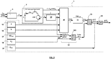
- Figure 3 shows the pinch detector 5 in more detail and the inputs of the pinch detector 5.
- the pinch detector 5 is suitable to detect a pinch at the closing member 1 actuated by the motor 2.
- the motor 2 is schematically represented by a DC motor equivalent model in figure 3 .
- this DC motor model includes a resistance Ra equivalent to the windings resistance, an inductance La equivalent to the windings inductance and a component of electromotive force EMF, connected in series.
- the pinch detector 5 includes a torque estimator 50, a torque to force converter 51, a first calculator 52 to calculate a friction force, a second calculator 53 to calculate an estimated pinch force and a comparator 54 to compare the estimated pinch force F pinch and a force limit F max .
- the pinch detector 5 has access to one or more memories 55-59 storing predetermined data including:
- the one or more memories 55-59 storing the above data can be internal memories of the pinch detector 5, or external memories (for example memories of the control apparatus 4).
- the motor angular velocity estimator 10 and the calculator 11 are external to the pinch detector 5. As previously indicated, they could be internal components of the pinch detector 5.
- the pinch detector 5 can be a functional element that is implemented by the controlling apparatus 4 executing a program for pinch detection. Therefore, the present disclosure also concerns a non-transitory computer readable medium including program instructions for causing a processor to execute the method for pinch detection described below in steps S5 to S11.
- an average (constant) value of the efficiency coefficient ⁇ could be used to estimate the motor torque ⁇ but this would provide a limited precision.
- the value of the energy conversion efficiency ⁇ is evaluated using an approximation function that gives an approximated value of ⁇ as a function of the motor torque.
- Figure 4 shows the energy conversion efficiency ⁇ as a function of the motor torque ⁇ and a linear approximation ⁇ ' of it, based on the equation (6), within a limited range of the torque values.
- Figure 4 also shows the relationship between the motor speed in RPM (rotation per minute) and the motor torque ⁇ . Two situations are represented: a first situation when the motor 2 is cold (dotted line) and a second situation when the motor 2 is hot (solid line).
- the torque estimator 50 estimates a motor torque ⁇ from current values of physical quantities of the motor 2.
- these physical quantities include a motor voltage, a motor current and a motor speed.
- the torque estimator 50 takes as inputs the voltage V supplied to the motor 2, the motor armature current I , and the motor angular velocity ⁇ .
- the voltage V is calculated by the calculator 11 using the measured battery voltage and the PWM duty cycle PWM DC . If the system 100 has no PWM controller embedded, the voltage V is equal to the battery voltage V batt .
- the motor armature current I is measured by the measuring circuit 3a.
- the angular velocity ⁇ is provided by the estimator 10, as explained later.
- ⁇ b 1 ⁇ a ⁇ V ⁇ I ⁇
- the torque to force conversion coefficient T2F coef is a constant that is predetermined and stored in memory in the torque to force converter 53 .
- the coefficient T2F coef can be given by the motor manufacturer.
- the torque to force converter 51 calculates an estimated motor force F e based on the equation (10) and taking as input the estimated torque from the torque estimator 50.
- the output of the converter 51 gives a first estimation of the pinch force F pinch .
- the static friction force F sf can be approximated by a constant value. It is predetermined and stored in the memory 58.
- This viscosity damping coefficient can incorporate several viscosity damping coefficients of the mechanical system including the window 1 and the DC motor 2, like the viscosity damping coefficient between an armature shaft and bearings inside the DC motor, the viscosity damping coefficient of a worm-gear that connects the DC motor 2 and a mechanical part of the window lift system, the viscosity damping between the window 1 and seals around the window frame.
- the first calculator 52 calculates the friction force F f .
- the calculator 52 takes as inputs the angular motor speed ⁇ calculated by the estimator 10 and the coefficient VD coef stored in the memory 57 to calculate the viscosity damping force F vd using the equation (13).
- the calculator 52 adds the calculated viscosity damping force F vd and the static friction force F sf stored in the memory 58, to compute the estimated friction force F f .
- the second calculator 53 calculates the pinch force F pinch based on the equation (11), taking as inputs:
- the second calculator 53 calculates an estimation of the pinch force F pinch based on the following formula :
- F pinch T 2 F Coef ⁇ b ⁇ V ⁇ I ⁇ ⁇ a ⁇ V ⁇ I ⁇ F sf + VD Coef ⁇ ⁇
- the comparator 54 compares the estimated pinch force F pinch calculated by the second calculator 53 with the force limit F max stored in the memory 59.
- This force limit F max can be the maximum force the member (here a window in a vehicle) is allowed to exert on any object according to a standard.
- F max can be set to 100 N.
- the force limit F max can be less than the maximum force allowed by the standard, in order to detect a pinch in advance, before reaching this maximum force.
- the force limit F max is set to a value within a range between 50 N and 80 N, for example 70 N.
- the comparator 54 transmits a warning signal (output signal) indicating that a pinch has been detected to the control apparatus 4, in a step S11.
- a control signal is generated by the control apparatus 4 to reverse its direction of movement so as to open the member 1 (i.e., to change the closing movement rapidly into an opening movement), in a step S12.
- the control signal could only stop the movement of the member 1.
- top diagram of figure 5 represents the evolution over time of the pinch force exerted by the window 1 on the obstable (object) with respect to a force limit of 70 N.
- curves of pinch force are represented and correspond to:
- the top diagram of figure 6 shows an enlarged view of the four curves when the object is squeezed.
- the bottom diagram of figure 6 shows the window position during the same period of time.
- the third estimation F pinch_est_3 (using a constant energy conversion efficiency ⁇ 0 ) is far away from the measured pinch force F pinch_meas .
- the first estimation F pinch_est_1 under estimates the pinch force.
- the second estimation F pinch_est_2 over estimates the pinch force. It results from these experiments that the best estimations are F pinch_est_1 (when the linear approximation of ⁇ is used) and F pinch_est_2 (when the linear approximation of ⁇ and the introduction of the friction force are used at the same time).
- the over estimation of the pinch force ( F pinch_est_2 ) is better than the under estimation of the pinch force ( F pinch_est_1 ) because this allows earlier pinch detections, a faster reaction of the control apparatus 4 to control the motor 2 and consequently a faster opening of the window 1.
- Figure 7 illustrates a window moving scenario similar to the one shown in figure 5 , including the stages (1) to (4), but in which the window is moving with a lower speed and is squeezing an obstacle O with a lowest stiffness.
- the battery voltage V batt is 10 V and the obstacle stiffness k o is 5 N/mm.
- the presence of an obstacle causes that the measured pinch force increases.
- the obstacle compression is illustrated in more detail in figure 8 that shows (see top diagram) the measured pinch force F pinch_measured , the first estimated pinch force F pinch_estimated_1 , the second estimated pinch force F pinch_estimated_2 and the third estimated pinch force F pinch_estimated_3 .
- Figure 9 illustrates a window moving scenario almost similar to the one shown in figure 5 , including the stages (1) to (4), but in which the battery voltage V batt is 13 V and there is no obstacle placed in the space left between the window 1 and the window frame.
- the window 1 is completely closed.
- the window 1 continued opening until it reached half height in the stage (2).
- the window 1 is moving upward until it is closed completely.
- the pinch detector 5 does not make a false detection of a pinch.
- the first and second estimated forces F pinch_estimated_1 and F pinch_estimated_2 are zero or almost zero.
- the present disclosure of pinch detection processes the measured current I , the measured voltage supply V batt and the estimated angular velocity ⁇ , and gives an estimation of the pinch force F pinch .
- the most important advantages of the present disclosure are that :
- the measuring circuit to measure a motor voltage could measure the voltage V supplying directly the motor.
- the energy efficiency coefficient of the motor is approximated by a linear function.
- a function of second order, or third order, or any other function giving an approximation of the energy conversion efficiency as a function of the motor torque could be used.
Landscapes
- Engineering & Computer Science (AREA)
- Power Engineering (AREA)
- Power-Operated Mechanisms For Wings (AREA)
Abstract
Description
- The present disclosure relates to the field of opening and closing member actuated by a motor, especially members such as power windows, sliding doors or sliding roofs in vehicles, which are provided with an anti-pinch detector to provide protection against injuries. More specifically, the present disclosure relates to a pinch detector suitable to detect a pinch at a closing member, a control apparatus for controlling the member actuated by a motor, and a method to detect a pinch at a closing member.
- Power windows (i.e., windows activated by an electric motor) are getting very popular nowadays, even in low-range vehicles.
- It happens that children try to put their neck or hands out through the window. If anyone operates the window switch to close the window at the same time, it may cause suffocation or injuries to the child. The risk also arises in case of power windows which are programmed to operate without even the need to press the switch, for example when a global closing function is activated.
- Windows are moved with clamping forces of up to 350 N. This means that a thin glass plate of only about 8 mm thickness can press up to 35 kg (e.g. onto a child's hand or head). It takes only 98 N to suffocate or injure a small child. To avoid such mishaps, an anti-pinch technology has been developed.
- The anti-pinch technology of a power window has to meet standards for example issued by the European Union and/or the United States. According to known standards, the maximum force a power window is allowed to exert on any object is 100 N and compliance with this limit must be monitored and enforced in a range of 4 mm to 200 mm minimum from the top window frame, as shown in
figure 1 . It is also important to deactivate the anti-pinch algorithm immediately before the window seal is reached (distance 4 mm from top seal), so that the window can close completely. In addition, to avoid overload and damage to the window motor, blocking must not last too long. - Document
US 2014/239867 A1 discloses a pinch detection apparatus for an opening and closing member actuated by a motor which comprises a reference data storage portion calculating load data on the basis of a rotation speed of the motor and an environmental temperature. - Document
US 2003/051555 A1 discloses a pinch detection system based on the calculation of reference motor torque using voltage and speed measurements. To this end, it requires at least one dedicated speed sensor, such as an encoder or a Hall effect sensor, that determines the rotational speed of the motor. A voltage sensor provides information to a force calculator which calculates the motor force. A difference between an actual force and a reference force can thus be determined. A pinch condition is indicated if the force difference exceeds a predetermined threshold. - Document
US 6239610 B1 discloses a solution based on the voltage induced in the armature motor of the electric drive system used for moving the window. - Lots of known solutions require an additional equipment such as force or speed sensors, which involves an additional cost, require more space in a relatively constrained environment and does not allow to increase the reliability of the entire system.
- Document
CN101220724A discloses an anti-pinch device for a power window requiring no additional sensor. An armature current signal is obtained and it is judged whether or not the motion of the window is obstructed by an obstacle according to the current and using a constant current threshold. - When a window in a vehicle clamps an obstacle, for example a body part of a passenger, the window applies a clamping force on this obstacle. A direct measurement of this force requires the use of an additional equipment, which generates additional costs.
- There is a need for improving existing anti-pinch solutions in order to at least partially overcome the aforementioned issues and drawbacks.
- The present disclosure concerns a pinch detector suitable to detect a pinch at a closing member actuated by a motor, including
a torque estimator that estimates a motor torque from current values of physical quantities of the motor including a motor voltage, a motor current and a motor speed, using coefficients of an approximation function that calculates an energy conversion efficiency of the motor as a function of the motor torque;
a converter that calculates a first estimation of a pinch force exerted by the opening and closing member on a pinched object by converting the estimated motor torque into an estimated pinch force using a torque to force conversion coefficient;
a comparator that compares the estimated pinch force with a predetermined force limit in order to detect a pinch based on the comparison result. - The present pinch detector can efficiently detect the occurrence of a pinch at the closing member based on simple calculations. It is fast, requires only a low resource consumption and easy to implement. It is also easy to adjust the pinch detector to the installation of the member by adjusting a few parameters. In addition, motor current and motor voltage can be simply measured. These measurements also allow to estimate the motor speed by known methods.
- In some embodiments, the torque estimator calculates an estimated motor torque by using two coefficients of a function of linear approximation.
- The torque estimator can calculate an estimated motor torque by using the equation

a and b are the two linear coefficients of the linear function
- that calculates the energy conversion efficiency η of the motor as a function of the motor torque τ;
- V, I and ω are respectively the motor voltage, motor current and motor angular speed.
- The pinch estimator can further include
a first calculator that calculates an estimation of a friction force exerted by the member on the object; and
a second calculator that calculates a second estimation of the pinch force by subtracting the estimated friction force from the estimated pinch force calculated by the converter. - The introduction of the estimated friction force for the estimation of the pinch force allows to obtain a better estimated pinch force, more similar to a measured pinch force.
- In a particular embodiment, the comparator compares the estimated pinch force output from the second calculator with the predetermined limit in order to detect a pinch based on the comparison result.
- The first calculator can calculate the friction force as the sum of a static friction force and a viscosity damping force.
- The first calculator can calculate an approximation of the viscosity damping force by multiplying the motor speed with a viscosity damping coefficient.
- The first calculator can obtain a fixed value of the friction force from a memory.
- The present disclosure also concerns a control apparatus for controlling an opening and closing member actuated by a motor, including a pinch detector as previously defined, and a portion that generates a control signal to control at least one of the two actions of stopping the member and reversing the direction of movement of the member, when a pinch is detected.
- The present disclosure also concerns a system including
an opening and closing member;
a motor for activating the member;
a first measuring circuit to measure a motor current;
a second measuring circuit to measure a motor voltage;
a motor angular speed estimator that estimates an angular speed of the motor from the measured motor voltage and the measured motor current;
a pinch detector as previously defined. - The present disclosure also concerns a vehicle including the system above defined.
- The present disclosure also concerns a method to detect a pinch at a closing member actuated by a motor, including the steps of
estimating a motor torque from current values of physical quantities of the motor including a motor voltage, a motor current and a motor speed, using coefficients of an approximation function that calculates an energy conversion efficiency of the motor as a function of the motor torque;
calculating a first estimation of a pinch force exerted by the closing member on a pinched object by converting the estimated motor torque into an estimated pinch force using a torque to force conversion coefficient; comparing the estimated pinch force with a predetermined force limit in order to detect a pinch based on the comparison result - Advantageously, the step of estimating the motor torque uses the equation

a and b are the two linear coefficients of the linear function
- that calculates the energy conversion efficiency η of the motor as a function of the motor torque τ ;
- V, I and ω are respectively the motor voltage, motor current and motor angular speed.
- The method can further include the steps of
calculating an estimation of a friction force exerted by the member on the object; and
calculating a second estimation of the pinch force by subtracting the estimated friction force from the estimated pinch force. - The present disclosure further concerns a non-transitory computer readable medium including program instructions for causing a processor to execute the method.
- Other features, purposes and advantages of the disclosure will become more explicit by means of reading the detailed statement of the non-restrictive embodiments made with reference to the accompanying drawings.
-
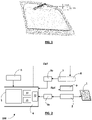
Figure 1 shows an obstacle placed in a space left between a window and a door frame, in a vehicle, and a range of vertical positions in which compliance with a limit of pinch force defined by standards must be monitored. -
Figure 2 represents a system including a closing and opening member equipped with a pinch detector, according to a particular embodiment. -
Figure 3 shows a functional block diagram of the pinch detector offigure 2 . -
Figure 4 shows an approximation function of an energy conversion efficiency of the motor offigure 2 . -
Figure 5 shows a member movement scenario, the member having a high speed, and, during this scenario, the evolutions over time of a measured pinch force and different approximations of the pinch force. -
Figure 6 shows an enlarged view of the time period of squeezing offigure 5 . -
Figure 7 shows the same member movement scenario, the member having a low speed, and, during this scenario, the evolutions over time of a measured pinch force and different approximations of the pinch force. -
Figure 8 shows an enlarged view of the time period of squeezing offigure 7 . -
Figure 9 shows a similar member movement scenario but without obstacle, the member having a middle (normal) speed, and, during this scenario, the evolutions over time of a measured pinch force and different approximations of the pinch force. -
Figure 10 represents a flow chart of a method of pinch detection, corresponding to the operation of the pinch detector offigure 3 . - The present disclosure relates to pinch detection to detect a pinch at a closing member actuated by a motor (for example a power window in a vehicle) and is more precisely dedicated to pinch detection based on an estimation of a pinch force with which the member pinches, or clamps, an object, such as a body part.
- With reference to
figure 2 , a first embodiment of a closing andopening system 100 with an anti-pinch protection includes amovable member 1, anelectric motor 2 for actuating themember 1, one ormore measuring circuits motor 2, acontrol apparatus 4 for controlling themotor 2, and apinch detector 5 for pinch detection at the closingmember 1. - The
movable member 1 is an opening and closing member such as a window, a door, a roof, a shutter, etc., that can move, for example in translation or rotation, between a closed position where the member closes an opening area and an open position where the member is removed from the opening area. - For example, the motor is a DC (direct current) motor powered by a direct current source (power source 7), e.g. an electrical battery, for supplying power to the
motor 2. - In the first embodiment, a
PWM controller 8 can be used to control supplying power as a PWM signal to themotor 2. The PWM signal is characterized by a PWM frequency and a PWM duty cycle. The PWM duty cycle can vary during the motor operation. For example, the PWM duty cycle can increase from an initial value (0% or more) to a final value, that is usually 100% (but could be less than 100%), when the motor starts. Then, it is stationary when themotor 2 operates at full speed and it finally decreases before stopping. ThePWM controller 8, shown in dotted lines infigure 2 , is optional. In other embodiments, thesystem 100 does not include aPWM controller 8. - A structure for supplying a direct voltage V to the
motor 2 can include thevoltage battery 7 that supplies a direct and fixed voltage Vbatt, thePWM controller 8 that supplies a PWM signal, and a H-bridge circuit 9 that receives as inputs the PWM signal generated by thePWM controller 8 and the direct battery voltage Vbatt supplied by thebattery 7 and produces as an output a direct voltage V supplied to themotor 2. - The
control apparatus 4 controls themotor 2 to move the closing and openingmember 1. It has aportion 40 that generates a control signal to control the movement of themotor 2 andmember 1. In some embodiments, the motor movement is controlled by a control signal Sig2 generated by thecontrol apparatus 4 and transmitted to thePWM controller 8, as represented infigure 2 . In this way, the H-bridge circuit 9 is controlled through thePWM controller 8. In other embodiments, thesystem 100 does not include aPWM controller 8. In that case, a control signal Sig1 is generated by thecontrol apparatus 4 and transmitted directly to the H-bridge circuit 9, as shown infigure 2 . It allows to control the motor direction movement (clockwise, counterclockwise and stop). - A user interface means can also be provided to enter user commands, for example to stop or move the member. It can include for example a
window command button 6 that can be pressed up to move up thewindow 1 or pressed down to move down thewindow 1. - In the first embodiment, the
motor 2 is equipped with two measuringcircuits motor 2, including a current and a voltage. The motor current can be an armature current I flowing through an armature winding of themotor 2, and the voltage V can be the direct voltage supplied to themotor 2. - In operation, the measuring
circuit 3a measures the armature current I in a step S2, and the measuringcircuit 3b measures the battery voltage Vbatt supplied to the motor through the H-bridge circuit 9 in a step S1. Each measuringcircuit control apparatus 4 by the measuringcircuits - In a step S4, a
calculator 11 calculates the direct voltage V supplied to themotor 2 using the equation V = Vbatt * PWMDC, where PWMDC is the PWM duty cycle of thePWM controller 8 and Vbatt is the battery voltage measured by the measuringcircuit 3b. Thecalculator 11 can be a software or hardware component. It can be implemented in thecontrol apparatus 4. It can be a component of thepinch detector 5. As previously indicated, in some embodiments, thesystem 100 does not include aPWM controller 8. In that case, the voltage supplied to the motor is equal to the battery voltage Vbatt. - In the first embodiment, in a step S3, an
angular velocity estimator 10 estimates a motor angular velocity or speed ω, based on the shaft angular position ϕ. Actually, in the present embodiment, the shaft angular position is not measured directly, which allows to avoid an extra external sensor embedded in the vehicle. The shaft angular position ϕ is estimated by a specially dedicated ripple count algorithm using the measured battery voltage Vbatt and measured armature current I flowing through the windings (armature) of themotor 2. Current ripples are small current fluctuations associated with the commutation phenomenon of a DC motor. A typical commutated brushed direct current (BDC) motor works by use of brushes which carry current to the commutation surfaces which in turn power the coils that create magnetic field to produce torque on the motor shaft. As the motor shaft rotates, the brushes come into contact with a different set of commutation surfaces. Most of the time, each brush touches two commutation surfaces. However, during every transition, each brush touches only one contact for a brief instant. During this transition, the current path changes and the internal resistance and inductance change. This in turn alters the current draw by the motor. The repetition of this process causes the current ripple which is seen on such motors. The number of ripples per one full motor shaft revolution corresponds to the number of poles. The rotational position of the shaft is determined based on detected ripples and then counted. - The
angular velocity estimator 10 can be a software or hardware component. It can be implemented in thecontrol apparatus 4. It can be a component of thepinch detector 5. - The
pinch detector 5 can be part of thecontrol apparatus 4. In operation, it implements the method (or algorithm) of pinch detection, described thereafter, to detect a pinch at the opening and closingmember 1. -
Figure 3 shows thepinch detector 5 in more detail and the inputs of thepinch detector 5. - The
pinch detector 5 is suitable to detect a pinch at the closingmember 1 actuated by themotor 2. Themotor 2 is schematically represented by a DC motor equivalent model infigure 3 . As shown infigure 3 , this DC motor model includes a resistance Ra equivalent to the windings resistance, an inductance La equivalent to the windings inductance and a component of electromotive force EMF, connected in series. - The
pinch detector 5 includes atorque estimator 50, a torque to forceconverter 51, afirst calculator 52 to calculate a friction force, asecond calculator 53 to calculate an estimated pinch force and acomparator 54 to compare the estimated pinch force Fpinch and a force limit Fmax. - The
pinch detector 5 has access to one or more memories 55-59 storing predetermined data including: - two coefficients "a", "b" of a linear approximation function of an energy efficiency coefficient of the
motor 2; - a viscosity damping coefficient VDcoef of the
motor 2; - a static friction force Fsf of the
motor 2; - a pinch force limit Fmax, for example 100 N, that should not be exceeded when an object is squeezed by the
member 1 in a closing movement of themember 1. - The one or more memories 55-59 storing the above data can be internal memories of the
pinch detector 5, or external memories (for example memories of the control apparatus 4). - In the presently described embodiment, the motor
angular velocity estimator 10 and thecalculator 11 are external to thepinch detector 5. As previously indicated, they could be internal components of thepinch detector 5. - The
pinch detector 5 can be a functional element that is implemented by thecontrolling apparatus 4 executing a program for pinch detection. Therefore, the present disclosure also concerns a non-transitory computer readable medium including program instructions for causing a processor to execute the method for pinch detection described below in steps S5 to S11. - The mechanical power P generated by the
motor 2 can be expressed as follows :
- The electrical power Pe consumed by the
motor 2 can be expressed as follows :
motor 2 and I is the motor current (i.e. the current flowing through the armature windings of the motor). - The energy conversion efficiency η of the
motor 2 can be expressed as follows :
- It results from a combination of the above equations (1) to (3) that the energy conversion efficiency η of the
motor 2 can be expressed as follows:
- Therefore, it results from the last expression of the above equation (4) that the motor torque τ can be estimated based on the following formula:

- An average (constant) value of the efficiency coefficient η could be used to estimate the motor torque τ but this would provide a limited precision. In order to improve the estimation of the motor torque τ, the value of the energy conversion efficiency η is evaluated using an approximation function that gives an approximated value of η as a function of the motor torque. In the first embodiment, this approximation function is a linear function that can be expressed as follows:

memories -
Figure 4 shows the energy conversion efficiency η as a function of the motor torque τ and a linear approximation η' of it, based on the equation (6), within a limited range of the torque values.Figure 4 also shows the relationship between the motor speed in RPM (rotation per minute) and the motor torque τ. Two situations are represented: a first situation when themotor 2 is cold (dotted line) and a second situation when themotor 2 is hot (solid line). - In operation, in a step S5 (following steps S1 to S4), the
torque estimator 50 estimates a motor torque τ from current values of physical quantities of themotor 2. In the present embodiment, these physical quantities include a motor voltage, a motor current and a motor speed. More precisely, in the first embodiment, thetorque estimator 50 takes as inputs the voltage V supplied to themotor 2, the motor armature current I, and the motor angular velocity ω. The voltage V is calculated by thecalculator 11 using the measured battery voltage and the PWM duty cycle PWMDC. If thesystem 100 has no PWM controller embedded, the voltage V is equal to the battery voltage Vbatt. The motor armature current I is measured by the measuringcircuit 3a. The angular velocity ω is provided by theestimator 10, as explained later. - The
torque estimator 50 uses the two coefficients "a" and "b" of the linear approximation function to calculate an estimation of the motor torque from the current values of V, I and ω, based on the following equation:
- The above equation (7) results from the equations (1), (6), (3) and (2), which give the equivalent expressions below:

- And, it results from the last expression of the above equation (8) that η can be expressed as follows:

- Based on the equations (5) and (9), the expression of the motor torque given by the equation (7) can be obtained.
- It is further assumed that an estimation of the motor force Fe can be calculated from the estimated motor torque τ, by conversion, based on the following expression:

torque estimator 50 and T2Fcoef is a torque to force conversion coefficient. - The torque to force conversion coefficient T2Fcoef is a constant that is predetermined and stored in memory in the torque to force
converter 53 . For example, the coefficient T2Fcoef can be given by the motor manufacturer. - In a step S6, the torque to force
converter 51 calculates an estimated motor force Fe based on the equation (10) and taking as input the estimated torque from thetorque estimator 50. The output of theconverter 51 gives a first estimation of the pinch force Fpinch . - Due to mechanical losses, the pinch force Fpinch effectively exerted by the
member 1 on a pinched object (i.e., an object squeezed between themember 1 actuated by themotor 2 and a member frame for example) is not equal to the estimated force Fe but is less than the estimated force Fe . The difference can be approximated by a friction force Ff. The relationship between the forces Fpinch and Fe can be expressed by the following equation:
- The friction force can be modelled as a sum of a static friction force Fsf and a viscosity damping force Fvd and expressed as follows:

- The static friction force Fsf can be approximated by a constant value. It is predetermined and stored in the
memory 58. - The viscosity damping force Fvd can be approximated as a function of the angular motor speed ω, and expressed as follows :

memory 57. This viscosity damping coefficient can incorporate several viscosity damping coefficients of the mechanical system including thewindow 1 and theDC motor 2, like the viscosity damping coefficient between an armature shaft and bearings inside the DC motor, the viscosity damping coefficient of a worm-gear that connects theDC motor 2 and a mechanical part of the window lift system, the viscosity damping between thewindow 1 and seals around the window frame. - In operation, in steps S7 and S8, the
first calculator 52 calculates the friction force Ff. In the step S7, thecalculator 52 takes as inputs the angular motor speed ω calculated by theestimator 10 and the coefficient VDcoef stored in thememory 57 to calculate the viscosity damping force Fvd using the equation (13). Then, in the step S8, thecalculator 52 adds the calculated viscosity damping force Fvd and the static friction force Fsf stored in thememory 58, to compute the estimated friction force Ff. Thus, the estimation of the friction force is calculated by thefirst calculator 52 based on the following expression:
- Then, in a step S9, the
second calculator 53 calculates the pinch force Fpinch based on the equation (11), taking as inputs: - the output from the torque to force converter 51 (e.g. the estimated force Fe calculated based on the equation 10), and
- the output from the first calculator 52 (e.g. the estimated friction force Ff calculated based on the equation 14).
- Thus, the
second calculator 53 calculates an estimation of the pinch force Fpinch based on the following formula :
- Then, in a step S10, the
comparator 54 compares the estimated pinch force Fpinch calculated by thesecond calculator 53 with the force limit Fmax stored in thememory 59. This force limit Fmax can be the maximum force the member (here a window in a vehicle) is allowed to exert on any object according to a standard. For example, Fmax can be set to 100 N. Alternatively, the force limit Fmax can be less than the maximum force allowed by the standard, in order to detect a pinch in advance, before reaching this maximum force. For example, the force limit Fmax is set to a value within a range between 50 N and 80 N, for example 70 N. When the estimated pinch force Fpinch exceeds the force limit Fmax, thecomparator 54 transmits a warning signal (output signal) indicating that a pinch has been detected to thecontrol apparatus 4, in a step S11. - When a pinch is detected, and upon reception of the warning signal from the
pinch detector 4, a control signal is generated by thecontrol apparatus 4 to reverse its direction of movement so as to open the member 1 (i.e., to change the closing movement rapidly into an opening movement), in a step S12. Alternatively, the control signal could only stop the movement of themember 1. - The most challenging situation for pinch detection is when the window (or more generally the member 1) is closing with the fastest speed and squeezing the stiffest obstacle. Let's consider a use case in which the battery voltage Vbatt is equal to 16 V, which causes the window to move fast, and the obstacle stiffness ko is 65 N/mm, which corresponds to a very stiff obstacle. An algorithm of pinch detection in a window movement scenario is represented schematically in the top diagram of
figure 5 that shows the successive positions of thewindow 1 in successive stages of the window movement scenario: - stage (1): the window that is initially completely closed is slightly opened and stopped;
- stage (2): the opening of the window is then continued until half the height of the window and stopped in this intermediate position;
- stage (3): the window is then closed but stopped in another intermediate position not completely closed and an obstacle "O" having the given stiffness ko = 65 N/mm is placed in the left space between the
window 1 and the window frame; - stage (4): the window starts closing again and squeezes the obstacle O.
- In addition, the top diagram of
figure 5 represents the evolution over time of the pinch force exerted by thewindow 1 on the obstable (object) with respect to a force limit of 70 N. Four curves of pinch force are represented and correspond to: - the measured pinch force, referenced as Fpinh_meas,
- a first estimated pinch force, referenced as Fpinch_est_1, output directly from the
converter 51, that is calculated based (only) on the approximation of the energy conversion efficiency η; - a second estimated pinch force, referenced as Fpinh_est_2, output from the
second calculator 53, that is calculated based on the approximation of the energy conversion coefficient η and on taking in account the friction force (as a correction of the estimated force); - a third estimated pinch force, referenced as Fpinch_est_3, that is calculated based on a constant energy conversion efficiency η0 (without any other approximation or correction).
- The top diagram of
figure 6 shows an enlarged view of the four curves when the object is squeezed. The bottom diagram offigure 6 shows the window position during the same period of time. The third estimation Fpinch_est_3 (using a constant energy conversion efficiency η0 ) is far away from the measured pinch force Fpinch_meas. The first estimation Fpinch_est_1 under estimates the pinch force. The second estimation Fpinch_est_2 over estimates the pinch force. It results from these experiments that the best estimations are Fpinch_est_1 (when the linear approximation of η is used) and Fpinch_est_2 (when the linear approximation of η and the introduction of the friction force are used at the same time). In practice, the over estimation of the pinch force (Fpinch_est_2 ) is better than the under estimation of the pinch force (Fpinch_est_1 ) because this allows earlier pinch detections, a faster reaction of thecontrol apparatus 4 to control themotor 2 and consequently a faster opening of thewindow 1. -
Figure 7 illustrates a window moving scenario similar to the one shown infigure 5 , including the stages (1) to (4), but in which the window is moving with a lower speed and is squeezing an obstacle O with a lowest stiffness. In this example, the battery voltage Vbatt is 10 V and the obstacle stiffness ko is 5 N/mm. The presence of an obstacle causes that the measured pinch force increases. The obstacle compression is illustrated in more detail infigure 8 that shows (see top diagram) the measured pinch force Fpinch_measured, the first estimated pinch force Fpinch_estimated_1, the second estimated pinch force Fpinch_estimated_2 and the third estimated pinch force Fpinch_estimated_3. These experiments show that the estimated force Fpinch_estimated_2 actually gives the best prediction of the measured pinch force. This prediction is satisfactory and meets requirements to detect pinch before the force exceeds 100 N. -
Figure 9 illustrates a window moving scenario almost similar to the one shown infigure 5 , including the stages (1) to (4), but in which the battery voltage Vbatt is 13 V and there is no obstacle placed in the space left between thewindow 1 and the window frame. Initially, thewindow 1 is completely closed. Then, after slightly opening thewindow 1 to a position of -350 ripples, thewindow 1 continued opening until it reached half height in the stage (2). Then, in the stage (3), thewindow 1 is moving upward until it is closed completely. Thepinch detector 5 does not make a false detection of a pinch. The first and second estimated forces Fpinch_estimated_1 and Fpinch_estimated_2 are zero or almost zero. - The three scenarios illustrated in
figures 5 ,7 and9 show the satisfactory estimation of the pinch force made by thepinch detector 5. - The present disclosure of pinch detection processes the measured current I, the measured voltage supply Vbatt and the estimated angular velocity ω, and gives an estimation of the pinch force Fpinch. The most important advantages of the present disclosure are that :
- the pinch detection is based on only one simple formula given by the equation (15);
- the
pinch detector 5 is easy to configure and adjust to the member installation : only two parameters VDcoef and Ff, depending on the installation receiving the member 1 (for example the door system receiving the window in a vehicle), and the approximation function of the efficiency coefficient η, depending on themotor 2, need to be characterized and set; - it is only required to measure the motor current I and the voltage supply Vbatt.
- In another embodiment, the measuring circuit to measure a motor voltage could measure the voltage V supplying directly the motor.
- In the first embodiment, the energy efficiency coefficient of the motor is approximated by a linear function. Alternatively, a function of second order, or third order, or any other function giving an approximation of the energy conversion efficiency as a function of the motor torque could be used.
Claims (15)
- A pinch detector (5) suitable to detect a pinch at a closing member (1) actuated by a motor (2), including
a torque estimator (50) that estimates a motor torque (τ) from current values of physical quantities of the motor (2) including a motor voltage (V), a motor current (/) and a motor speed (ω), using coefficients of an approximation function that calculates an energy conversion efficiency (η) of the motor (2) as a function of the motor torque (z);
a converter (51) that calculates a first estimation of a pinch force (Fpinch ) exerted by the opening and closing member on a pinched object by converting the estimated motor torque (τ) into an estimated pinch force (Fe ) using a torque to force conversion coefficient (T2Fcoef );
a comparator (54) that compares the estimated pinch force (Fpinch ) with a predetermined force limit (Fmax ) in order to detect a pinch based on the comparison result. - The pinch detector of claim 1, wherein the torque estimator (50) calculates an estimated motor torque (τ) by using two coefficients (a, b) of a function of linear approximation.
- The pinch detector according to claim 1 or 2, wherein the torque estimator (50) calculates an estimated motor torque τ by using the equation

a and b are the two linear coefficients of the linear function that calculates the energy conversion efficiency η of the motor as a function of the motor torque τ ;V, I and ω are respectively the motor voltage, motor current and motor angular speed.
 - The pinch detector according to any of claims 1 to 3, further including a first calculator (52) that calculates an estimation of a friction force (Ff ) exerted by the member (1) on the object; and
a second calculator (53) that calculates a second estimation of the pinch force (Fpinch ) by subtracting the estimated friction force (Ff ) from the estimated pinch force (Fe ) calculated by the converter. - The pinch detection according to claim 4, wherein the comparator (54) compares the estimated pinch force (Fpinch ) output from the second calculator (53) with the predetermined limit (Fmax ) in order to detect a pinch based on the comparison result.
- The pinch detector according to claim 4 or 5, wherein the first calculator (52) calculates the friction force (Ff ) as the sum of a static friction force (Fsf ) and a viscosity damping force (Fvd ).
- The pinch detector according to claim 6, wherein the first calculator (52) calculates an approximation of the viscosity damping force (Fvd ) by multiplying the motor speed (ω) with a viscosity damping coefficient (VDcoef).
- The pinch detector according to claim 6 or 7, wherein the first calculator (52) reads a fixed value of the friction force in a memory.
- A control apparatus (4) for controlling an opening and closing member (1) actuated by a motor (2), including a pinch detector (5) according to any of claims 1 to 8, and a portion that generates a control signal to control at least one of the two actions of stopping the member and reversing the direction of movement of the member (1), when a pinch is detected.
- A system including
an opening and closing member (1);
a motor (2) for activating the member (1);
a first measuring circuit (3b) to measure a motor voltage (V);
a second measuring circuit (3a) to measure a motor current (/);
a motor angular speed estimator (10) that estimates an angular speed (ω) of the motor (2) from the measured motor voltage (V) and the measured motor current (V);
a pinch detector (5) according to any of claims 1 to 9. - A vehicle including the system of claim 10.
- A method to detect a pinch at a closing member (1) actuated by a motor (2), including the steps of
estimating (S5) a motor torque (τ) from current values of physical quantities of the motor (2) including a motor voltage (V), a motor current (/) and a motor speed (ω), using coefficients of an approximation function that calculates an energy conversion efficiency (η) of the motor (2) as a function of the motor torque (τ);
calculating (S6-S9) a first estimation of a pinch force (Fpinch ) exerted by the closing member on a pinched object by converting the estimated motor torque (τ) into an estimated pinch force (Fe ) using a torque to force conversion coefficient (T2Fcoef );
comparing (S10) the estimated pinch force (Fpinch ) with a predetermined force limit (Fmax ) in order to detect a pinch based on the comparison result. - The method according to claim 12, wherein the step (S5) of estimating the motor torque uses the equation

a and b are the two linear coefficients of the linear function that calculates the energy conversion efficiency η of the motor as a function of the motor torque τ ;V, I and ω are respectively the motor voltage, motor current and motor angular speed.
 - The method according to claim 12 or 13, further including the steps of calculating (S7-S8) an estimation of a friction force (Ff ) exerted by the member(1) on the object; and
calculating (S9) a second estimation of the pinch force (Fpinch ) by subtracting the estimated friction force (Ff ) from the estimated pinch force (Fe ). - A non-transitory computer readable medium including program instructions for causing a processor to execute the method according to any of claims 12 to 14.
Priority Applications (3)
| Application Number | Priority Date | Filing Date | Title |
|---|---|---|---|
| EP20208151.9A EP4001568B1 (en) | 2020-11-17 | 2020-11-17 | Pinch detection based on estimated pinch force |
| US17/513,809 US11735905B2 (en) | 2020-11-17 | 2021-10-28 | Pinch detection based on estimated pinch force |
| CN202111346689.XA CN114513157A (en) | 2020-11-17 | 2021-11-15 | Clamp detection based on estimated clamp force |
Applications Claiming Priority (1)
| Application Number | Priority Date | Filing Date | Title |
|---|---|---|---|
| EP20208151.9A EP4001568B1 (en) | 2020-11-17 | 2020-11-17 | Pinch detection based on estimated pinch force |
Publications (2)
| Publication Number | Publication Date |
|---|---|
| EP4001568A1 true EP4001568A1 (en) | 2022-05-25 |
| EP4001568B1 EP4001568B1 (en) | 2024-05-01 |
Family
ID=73475869
Family Applications (1)
| Application Number | Title | Priority Date | Filing Date |
|---|---|---|---|
| EP20208151.9A Active EP4001568B1 (en) | 2020-11-17 | 2020-11-17 | Pinch detection based on estimated pinch force |
Country Status (3)
| Country | Link |
|---|---|
| US (1) | US11735905B2 (en) |
| EP (1) | EP4001568B1 (en) |
| CN (1) | CN114513157A (en) |
Families Citing this family (1)
| Publication number | Priority date | Publication date | Assignee | Title |
|---|---|---|---|---|
| CN117621033A (en) * | 2022-08-15 | 2024-03-01 | 上海微创医疗机器人(集团)股份有限公司 | Control method, device and robot for clamping components |
Citations (8)
| Publication number | Priority date | Publication date | Assignee | Title |
|---|---|---|---|---|
| US5977732A (en) * | 1997-02-04 | 1999-11-02 | Nissan Motor Co., Ltd. | Apparatus and method for determining presence or absence of foreign object or the like caught in power-open-and-closure mechanism |
| US6051945A (en) * | 1999-01-25 | 2000-04-18 | Honda Giken Kogyo Kabushiki Kaisha | Anti-pinch safety system for vehicle closure device |
| US6239610B1 (en) | 1996-09-16 | 2001-05-29 | Robert Bosch Gmbh | Arrangement for detecting jamming situations in electric drives |
| US20030051555A1 (en) | 2001-09-13 | 2003-03-20 | Siemens Vdo Automotive Corporation | Pinch detection system |
| US20050187688A1 (en) * | 2001-12-27 | 2005-08-25 | Lear Corporation | Method of detecting obstructions caused by motor-driven power windows and similar devices using fuzzy logic algorithms |
| CN101220724A (en) | 2008-01-30 | 2008-07-16 | 张建华 | Anti-clip control method for electric window of vehicle |
| US20090056385A1 (en) * | 2007-09-05 | 2009-03-05 | Kabushiki Kaisha Toshiba | Motor controller and washing machine |
| US20140239867A1 (en) | 2013-02-28 | 2014-08-28 | Aisin Seiki Kabushiki Kaisha | Pinch detection apparatus for opening-and-closing member, and opening-and-closing member apparatus |
Family Cites Families (34)
| Publication number | Priority date | Publication date | Assignee | Title |
|---|---|---|---|---|
| DE3532078A1 (en) | 1984-09-13 | 1986-04-17 | Aisin Seiki K.K., Kariya, Aichi | ENGINE CONTROL METHOD AND DEVICE THEREFOR |
| US7548037B2 (en) | 1992-04-22 | 2009-06-16 | Nartron Corporation | Collision monitoring system |
| AU6401994A (en) * | 1993-03-12 | 1994-09-26 | Prospects Corporation | Automatic venting system for a vehicle |
| EP0692856A3 (en) | 1994-07-14 | 1997-10-08 | Nartron Corp | Power window or panel controller |
| JP3467875B2 (en) | 1994-12-13 | 2003-11-17 | 株式会社デンソー | Power window control device |
| DE19601359A1 (en) | 1996-01-16 | 1997-07-17 | Fraunhofer Ges Forschung | Method for controlling a DC drive |
| JPH11324481A (en) | 1998-05-20 | 1999-11-26 | Denso Corp | Power window device with pinch prevention function |
| US6362584B1 (en) | 2000-04-19 | 2002-03-26 | Meritor Light Vehicle Technology L.L.C. | Virtual sensor for window position |
| US6633147B2 (en) * | 2001-05-25 | 2003-10-14 | Motorola, Inc. | Method for closing a motor driven window |
| US6573677B2 (en) * | 2001-06-18 | 2003-06-03 | Motorola, Inc. | Method of compensating for abrupt load changes in an anti-pinch window control system |
| US6794837B1 (en) | 2002-05-31 | 2004-09-21 | Valeo Electrical Systems, Inc. | Motor speed-based anti-pinch control apparatus and method with start-up transient detection and compensation |
| FR2845165B1 (en) | 2002-09-26 | 2004-12-24 | Arvinmeritor Light Vehicle Sys | OBSTACLE DETECTOR FOR A VEHICLE OPENING ELEMENT |
| JP4761116B2 (en) | 2005-05-30 | 2011-08-31 | アイシン精機株式会社 | Pinch detection system |
| JP4131272B2 (en) | 2005-06-28 | 2008-08-13 | オムロン株式会社 | Window opening and closing control device |
| US7518325B2 (en) | 2006-09-29 | 2009-04-14 | Silicon Laboratories Inc. | System and method for controlling anti-pinch powered windows |
| DE102007056228B4 (en) | 2007-11-22 | 2010-04-22 | Continental Automotive Gmbh | Method and device for correcting temperature-dependent changes in the mechanical properties of a movable closing part of a vehicle |
| US20100039057A1 (en) | 2008-04-30 | 2010-02-18 | Tsai Kune-Muh | Anti-pinch method and device for controlling an openable and closable body |
| DE102008042762A1 (en) | 2008-10-13 | 2010-04-15 | Robert Bosch Gmbh | Method and device for operating a anti-jamming function in an electric locking system |
| DE102008043483A1 (en) | 2008-11-05 | 2010-05-06 | Robert Bosch Gmbh | Method and device for activating monitoring by a anti-trap function in an electrical locking system |
| DE102009014808A1 (en) | 2009-03-25 | 2010-10-07 | Continental Automotive Gmbh | Method and device for driving a control element having a response delay of a drive device |
| US8720279B2 (en) | 2009-05-18 | 2014-05-13 | Freescale Semiconductor, Inc. | Object detection device with variable sensitivity electric field measurement circuit |
| DE102009028914A1 (en) | 2009-08-26 | 2011-03-03 | Robert Bosch Gmbh | Method for recognizing trapping case of closing device, involves determining variable of state, which indicates force for movement of closing element in closing direction |
| DE102011111450A1 (en) | 2011-08-30 | 2013-02-28 | Brose Fahrzeugteile Gmbh & Co. Kommanditgesellschaft, Hallstadt | Method and device for monitoring a drive unit having a rotating drive motor, in particular a window lifter |
| DE102012011117B4 (en) | 2012-06-05 | 2020-06-18 | Audi Ag | Adjustment system for a vehicle and method for adjusting an adjustable element for a vehicle |
| CN202899882U (en) | 2012-11-23 | 2013-04-24 | 同济大学 | Car window anti-pinch controller |
| US10884493B2 (en) | 2013-06-20 | 2021-01-05 | Uday Parshionikar | Gesture based user interfaces, apparatuses and systems using eye tracking, head tracking, hand tracking, facial expressions and other user actions |
| JP6390466B2 (en) | 2015-02-26 | 2018-09-19 | 株式会社デンソー | Opening / closing member control apparatus and opening / closing member control method |
| JP5940202B1 (en) | 2015-08-06 | 2016-06-29 | オムロンオートモーティブエレクトロニクス株式会社 | Opening and closing body control device |
| US9834175B2 (en) | 2015-10-22 | 2017-12-05 | U-Shin Ltd. | Door opening and closing device |
| US11313167B2 (en) | 2016-04-25 | 2022-04-26 | Magna Closures Inc. | System and method for detecting vehicular door movement due to non-contact using obstacle detection |
| AT518850B1 (en) * | 2016-07-13 | 2021-11-15 | Avl List Gmbh | Method for simulation-based analysis of a motor vehicle |
| JP6897599B2 (en) | 2018-02-21 | 2021-06-30 | 株式会社デンソー | Power window controller |
| JP6505896B2 (en) * | 2018-03-08 | 2019-04-24 | Ntn株式会社 | Electric brake device |
| US12227056B2 (en) | 2021-08-27 | 2025-02-18 | Nissan North America, Inc. | Systems and methods for adjusting vehicle windows |
-
2020
- 2020-11-17 EP EP20208151.9A patent/EP4001568B1/en active Active
-
2021
- 2021-10-28 US US17/513,809 patent/US11735905B2/en active Active
- 2021-11-15 CN CN202111346689.XA patent/CN114513157A/en active Pending
Patent Citations (8)
| Publication number | Priority date | Publication date | Assignee | Title |
|---|---|---|---|---|
| US6239610B1 (en) | 1996-09-16 | 2001-05-29 | Robert Bosch Gmbh | Arrangement for detecting jamming situations in electric drives |
| US5977732A (en) * | 1997-02-04 | 1999-11-02 | Nissan Motor Co., Ltd. | Apparatus and method for determining presence or absence of foreign object or the like caught in power-open-and-closure mechanism |
| US6051945A (en) * | 1999-01-25 | 2000-04-18 | Honda Giken Kogyo Kabushiki Kaisha | Anti-pinch safety system for vehicle closure device |
| US20030051555A1 (en) | 2001-09-13 | 2003-03-20 | Siemens Vdo Automotive Corporation | Pinch detection system |
| US20050187688A1 (en) * | 2001-12-27 | 2005-08-25 | Lear Corporation | Method of detecting obstructions caused by motor-driven power windows and similar devices using fuzzy logic algorithms |
| US20090056385A1 (en) * | 2007-09-05 | 2009-03-05 | Kabushiki Kaisha Toshiba | Motor controller and washing machine |
| CN101220724A (en) | 2008-01-30 | 2008-07-16 | 张建华 | Anti-clip control method for electric window of vehicle |
| US20140239867A1 (en) | 2013-02-28 | 2014-08-28 | Aisin Seiki Kabushiki Kaisha | Pinch detection apparatus for opening-and-closing member, and opening-and-closing member apparatus |
Also Published As
| Publication number | Publication date |
|---|---|
| EP4001568B1 (en) | 2024-05-01 |
| US11735905B2 (en) | 2023-08-22 |
| CN114513157A (en) | 2022-05-17 |
| US20220158442A1 (en) | 2022-05-19 |
Similar Documents
| Publication | Publication Date | Title |
|---|---|---|
| US11581829B2 (en) | Pinch detection based on motor current increase | |
| CN101916981B (en) | Method for preventing motor rotation blockage of automotive electric trunk and position sensor used thereby | |
| CN108386094B (en) | A kind of permanent magnetic linear synchronous motor is double to open automatic door control method | |
| JP2005351042A (en) | Opening and closing body control device | |
| CN111206838A (en) | Ripple anti-pinch position compensation method and device | |
| CN114016852B (en) | Automatic opening and closing control method and device for charging flap | |
| CN112012612B (en) | Anti-pinch safety control method, device and system for automatic door current detection | |
| ITTO20130129A1 (en) | SYSTEM AND METHOD FOR CHECKING AN ELECTRIC MOTOR WITHOUT CURRENT CONTINUOUS BRUSHES WITH SINE-PUMP DRIVING FOR A AUTOMOTIVE POWER ACTUATOR | |
| EP4001568B1 (en) | Pinch detection based on estimated pinch force | |
| JPH1162380A (en) | Inserting detection method of power window device | |
| JP7775912B2 (en) | Wiper control device | |
| CN114508276B (en) | Method and device for detecting potential pinching | |
| JP3675622B2 (en) | Power window device pinching detection method | |
| EP4001566B1 (en) | Pinch detection during motor restart | |
| CN116357192B (en) | A control method, device, box door assembly, delivery robot and storage cabinet | |
| JP2008150830A (en) | Control unit of opening and closing body for vehicle | |
| WO2023188035A1 (en) | Elevator door control device | |
| JPH04299096A (en) | Elevator door controller | |
| JP2008150828A (en) | Control unit of opening and closing body for vehicle | |
| US12088234B2 (en) | Driving of a single coil brushless DC motor | |
| JPH07212963A (en) | Automatic switchgear safety device | |
| KR20130031110A (en) | Control apparatus for power window | |
| JP5698012B2 (en) | Motor control device, opening / closing body control device, control method, and control program | |
| JP2782320B2 (en) | Electric drive | |
| JP2012001965A (en) | Movable-body driving device |
Legal Events
| Date | Code | Title | Description |
|---|---|---|---|
| PUAI | Public reference made under article 153(3) epc to a published international application that has entered the european phase |
Free format text: ORIGINAL CODE: 0009012 |
|
| STAA | Information on the status of an ep patent application or granted ep patent |
Free format text: STATUS: THE APPLICATION HAS BEEN PUBLISHED |
|
| AK | Designated contracting states |
Kind code of ref document: A1 Designated state(s): AL AT BE BG CH CY CZ DE DK EE ES FI FR GB GR HR HU IE IS IT LI LT LU LV MC MK MT NL NO PL PT RO RS SE SI SK SM TR |
|
| STAA | Information on the status of an ep patent application or granted ep patent |
Free format text: STATUS: REQUEST FOR EXAMINATION WAS MADE |
|
| 17P | Request for examination filed |
Effective date: 20221101 |
|
| RBV | Designated contracting states (corrected) |
Designated state(s): AL AT BE BG CH CY CZ DE DK EE ES FI FR GB GR HR HU IE IS IT LI LT LU LV MC MK MT NL NO PL PT RO RS SE SI SK SM TR |
|
| RAP3 | Party data changed (applicant data changed or rights of an application transferred) |
Owner name: APTIV TECHNOLOGIES LIMITED |
|
| STAA | Information on the status of an ep patent application or granted ep patent |
Free format text: STATUS: EXAMINATION IS IN PROGRESS |
|
| 17Q | First examination report despatched |
Effective date: 20230531 |
|
| GRAP | Despatch of communication of intention to grant a patent |
Free format text: ORIGINAL CODE: EPIDOSNIGR1 |
|
| STAA | Information on the status of an ep patent application or granted ep patent |
Free format text: STATUS: GRANT OF PATENT IS INTENDED |
|
| INTG | Intention to grant announced |
Effective date: 20231107 |
|
| RIN1 | Information on inventor provided before grant (corrected) |
Inventor name: ROMASZKO, MATEUSZ Inventor name: WOJTASINSKI, PAWEL |
|
| GRAS | Grant fee paid |
Free format text: ORIGINAL CODE: EPIDOSNIGR3 |
|
| GRAA | (expected) grant |
Free format text: ORIGINAL CODE: 0009210 |
|
| STAA | Information on the status of an ep patent application or granted ep patent |
Free format text: STATUS: THE PATENT HAS BEEN GRANTED |
|
| RAP1 | Party data changed (applicant data changed or rights of an application transferred) |
Owner name: APTIV TECHNOLOGIES AG |
|
| AK | Designated contracting states |
Kind code of ref document: B1 Designated state(s): AL AT BE BG CH CY CZ DE DK EE ES FI FR GB GR HR HU IE IS IT LI LT LU LV MC MK MT NL NO PL PT RO RS SE SI SK SM TR |
|
| REG | Reference to a national code |
Ref country code: GB Ref legal event code: FG4D |
|
| P01 | Opt-out of the competence of the unified patent court (upc) registered |
Effective date: 20240408 |
|
| REG | Reference to a national code |
Ref country code: CH Ref legal event code: EP |
|
| REG | Reference to a national code |
Ref country code: IE Ref legal event code: FG4D |
|
| REG | Reference to a national code |
Ref country code: DE Ref legal event code: R096 Ref document number: 602020030011 Country of ref document: DE |
|
| REG | Reference to a national code |
Ref country code: LT Ref legal event code: MG9D |
|
| REG | Reference to a national code |
Ref country code: NL Ref legal event code: MP Effective date: 20240501 |
|
| RAP4 | Party data changed (patent owner data changed or rights of a patent transferred) |
Owner name: APTIV TECHNOLOGIES AG |
|
| PG25 | Lapsed in a contracting state [announced via postgrant information from national office to epo] |
Ref country code: IS Free format text: LAPSE BECAUSE OF FAILURE TO SUBMIT A TRANSLATION OF THE DESCRIPTION OR TO PAY THE FEE WITHIN THE PRESCRIBED TIME-LIMIT Effective date: 20240901 |
|
| PG25 | Lapsed in a contracting state [announced via postgrant information from national office to epo] |
Ref country code: BG Free format text: LAPSE BECAUSE OF FAILURE TO SUBMIT A TRANSLATION OF THE DESCRIPTION OR TO PAY THE FEE WITHIN THE PRESCRIBED TIME-LIMIT Effective date: 20240501 |
|
| PG25 | Lapsed in a contracting state [announced via postgrant information from national office to epo] |
Ref country code: FI Free format text: LAPSE BECAUSE OF FAILURE TO SUBMIT A TRANSLATION OF THE DESCRIPTION OR TO PAY THE FEE WITHIN THE PRESCRIBED TIME-LIMIT Effective date: 20240501 Ref country code: HR Free format text: LAPSE BECAUSE OF FAILURE TO SUBMIT A TRANSLATION OF THE DESCRIPTION OR TO PAY THE FEE WITHIN THE PRESCRIBED TIME-LIMIT Effective date: 20240501 |
|
| PG25 | Lapsed in a contracting state [announced via postgrant information from national office to epo] |
Ref country code: GR Free format text: LAPSE BECAUSE OF FAILURE TO SUBMIT A TRANSLATION OF THE DESCRIPTION OR TO PAY THE FEE WITHIN THE PRESCRIBED TIME-LIMIT Effective date: 20240802 |
|
| PG25 | Lapsed in a contracting state [announced via postgrant information from national office to epo] |
Ref country code: PT Free format text: LAPSE BECAUSE OF FAILURE TO SUBMIT A TRANSLATION OF THE DESCRIPTION OR TO PAY THE FEE WITHIN THE PRESCRIBED TIME-LIMIT Effective date: 20240902 |
|
| REG | Reference to a national code |
Ref country code: AT Ref legal event code: MK05 Ref document number: 1682554 Country of ref document: AT Kind code of ref document: T Effective date: 20240501 |
|
| PG25 | Lapsed in a contracting state [announced via postgrant information from national office to epo] |
Ref country code: NL Free format text: LAPSE BECAUSE OF FAILURE TO SUBMIT A TRANSLATION OF THE DESCRIPTION OR TO PAY THE FEE WITHIN THE PRESCRIBED TIME-LIMIT Effective date: 20240501 |
|
| PG25 | Lapsed in a contracting state [announced via postgrant information from national office to epo] |
Ref country code: ES Free format text: LAPSE BECAUSE OF FAILURE TO SUBMIT A TRANSLATION OF THE DESCRIPTION OR TO PAY THE FEE WITHIN THE PRESCRIBED TIME-LIMIT Effective date: 20240501 |
|
| PG25 | Lapsed in a contracting state [announced via postgrant information from national office to epo] |
Ref country code: AT Free format text: LAPSE BECAUSE OF FAILURE TO SUBMIT A TRANSLATION OF THE DESCRIPTION OR TO PAY THE FEE WITHIN THE PRESCRIBED TIME-LIMIT Effective date: 20240501 |
|
| PG25 | Lapsed in a contracting state [announced via postgrant information from national office to epo] |
Ref country code: PL Free format text: LAPSE BECAUSE OF FAILURE TO SUBMIT A TRANSLATION OF THE DESCRIPTION OR TO PAY THE FEE WITHIN THE PRESCRIBED TIME-LIMIT Effective date: 20240501 |
|
| PG25 | Lapsed in a contracting state [announced via postgrant information from national office to epo] |
Ref country code: LV Free format text: LAPSE BECAUSE OF FAILURE TO SUBMIT A TRANSLATION OF THE DESCRIPTION OR TO PAY THE FEE WITHIN THE PRESCRIBED TIME-LIMIT Effective date: 20240501 |
|
| PG25 | Lapsed in a contracting state [announced via postgrant information from national office to epo] |
Ref country code: PT Free format text: LAPSE BECAUSE OF FAILURE TO SUBMIT A TRANSLATION OF THE DESCRIPTION OR TO PAY THE FEE WITHIN THE PRESCRIBED TIME-LIMIT Effective date: 20240902 Ref country code: PL Free format text: LAPSE BECAUSE OF FAILURE TO SUBMIT A TRANSLATION OF THE DESCRIPTION OR TO PAY THE FEE WITHIN THE PRESCRIBED TIME-LIMIT Effective date: 20240501 Ref country code: NO Free format text: LAPSE BECAUSE OF FAILURE TO SUBMIT A TRANSLATION OF THE DESCRIPTION OR TO PAY THE FEE WITHIN THE PRESCRIBED TIME-LIMIT Effective date: 20240801 Ref country code: NL Free format text: LAPSE BECAUSE OF FAILURE TO SUBMIT A TRANSLATION OF THE DESCRIPTION OR TO PAY THE FEE WITHIN THE PRESCRIBED TIME-LIMIT Effective date: 20240501 Ref country code: LV Free format text: LAPSE BECAUSE OF FAILURE TO SUBMIT A TRANSLATION OF THE DESCRIPTION OR TO PAY THE FEE WITHIN THE PRESCRIBED TIME-LIMIT Effective date: 20240501 Ref country code: IS Free format text: LAPSE BECAUSE OF FAILURE TO SUBMIT A TRANSLATION OF THE DESCRIPTION OR TO PAY THE FEE WITHIN THE PRESCRIBED TIME-LIMIT Effective date: 20240901 Ref country code: HR Free format text: LAPSE BECAUSE OF FAILURE TO SUBMIT A TRANSLATION OF THE DESCRIPTION OR TO PAY THE FEE WITHIN THE PRESCRIBED TIME-LIMIT Effective date: 20240501 Ref country code: GR Free format text: LAPSE BECAUSE OF FAILURE TO SUBMIT A TRANSLATION OF THE DESCRIPTION OR TO PAY THE FEE WITHIN THE PRESCRIBED TIME-LIMIT Effective date: 20240802 Ref country code: FI Free format text: LAPSE BECAUSE OF FAILURE TO SUBMIT A TRANSLATION OF THE DESCRIPTION OR TO PAY THE FEE WITHIN THE PRESCRIBED TIME-LIMIT Effective date: 20240501 Ref country code: ES Free format text: LAPSE BECAUSE OF FAILURE TO SUBMIT A TRANSLATION OF THE DESCRIPTION OR TO PAY THE FEE WITHIN THE PRESCRIBED TIME-LIMIT Effective date: 20240501 Ref country code: BG Free format text: LAPSE BECAUSE OF FAILURE TO SUBMIT A TRANSLATION OF THE DESCRIPTION OR TO PAY THE FEE WITHIN THE PRESCRIBED TIME-LIMIT Effective date: 20240501 Ref country code: AT Free format text: LAPSE BECAUSE OF FAILURE TO SUBMIT A TRANSLATION OF THE DESCRIPTION OR TO PAY THE FEE WITHIN THE PRESCRIBED TIME-LIMIT Effective date: 20240501 Ref country code: RS Free format text: LAPSE BECAUSE OF FAILURE TO SUBMIT A TRANSLATION OF THE DESCRIPTION OR TO PAY THE FEE WITHIN THE PRESCRIBED TIME-LIMIT Effective date: 20240801 |
|
| PGFP | Annual fee paid to national office [announced via postgrant information from national office to epo] |
Ref country code: DE Payment date: 20241016 Year of fee payment: 5 |
|
| PG25 | Lapsed in a contracting state [announced via postgrant information from national office to epo] |
Ref country code: DK Free format text: LAPSE BECAUSE OF FAILURE TO SUBMIT A TRANSLATION OF THE DESCRIPTION OR TO PAY THE FEE WITHIN THE PRESCRIBED TIME-LIMIT Effective date: 20240501 |
|
| PGFP | Annual fee paid to national office [announced via postgrant information from national office to epo] |
Ref country code: GB Payment date: 20241111 Year of fee payment: 5 |
|
| PGFP | Annual fee paid to national office [announced via postgrant information from national office to epo] |
Ref country code: FR Payment date: 20241129 Year of fee payment: 5 |
|
| PG25 | Lapsed in a contracting state [announced via postgrant information from national office to epo] |
Ref country code: EE Free format text: LAPSE BECAUSE OF FAILURE TO SUBMIT A TRANSLATION OF THE DESCRIPTION OR TO PAY THE FEE WITHIN THE PRESCRIBED TIME-LIMIT Effective date: 20240501 |
|
| PG25 | Lapsed in a contracting state [announced via postgrant information from national office to epo] |
Ref country code: CZ Free format text: LAPSE BECAUSE OF FAILURE TO SUBMIT A TRANSLATION OF THE DESCRIPTION OR TO PAY THE FEE WITHIN THE PRESCRIBED TIME-LIMIT Effective date: 20240501 |
|
| PG25 | Lapsed in a contracting state [announced via postgrant information from national office to epo] |
Ref country code: SK Free format text: LAPSE BECAUSE OF FAILURE TO SUBMIT A TRANSLATION OF THE DESCRIPTION OR TO PAY THE FEE WITHIN THE PRESCRIBED TIME-LIMIT Effective date: 20240501 Ref country code: RO Free format text: LAPSE BECAUSE OF FAILURE TO SUBMIT A TRANSLATION OF THE DESCRIPTION OR TO PAY THE FEE WITHIN THE PRESCRIBED TIME-LIMIT Effective date: 20240501 |
|
| PG25 | Lapsed in a contracting state [announced via postgrant information from national office to epo] |
Ref country code: SM Free format text: LAPSE BECAUSE OF FAILURE TO SUBMIT A TRANSLATION OF THE DESCRIPTION OR TO PAY THE FEE WITHIN THE PRESCRIBED TIME-LIMIT Effective date: 20240501 |
|
| PG25 | Lapsed in a contracting state [announced via postgrant information from national office to epo] |
Ref country code: SM Free format text: LAPSE BECAUSE OF FAILURE TO SUBMIT A TRANSLATION OF THE DESCRIPTION OR TO PAY THE FEE WITHIN THE PRESCRIBED TIME-LIMIT Effective date: 20240501 Ref country code: SK Free format text: LAPSE BECAUSE OF FAILURE TO SUBMIT A TRANSLATION OF THE DESCRIPTION OR TO PAY THE FEE WITHIN THE PRESCRIBED TIME-LIMIT Effective date: 20240501 Ref country code: RO Free format text: LAPSE BECAUSE OF FAILURE TO SUBMIT A TRANSLATION OF THE DESCRIPTION OR TO PAY THE FEE WITHIN THE PRESCRIBED TIME-LIMIT Effective date: 20240501 Ref country code: EE Free format text: LAPSE BECAUSE OF FAILURE TO SUBMIT A TRANSLATION OF THE DESCRIPTION OR TO PAY THE FEE WITHIN THE PRESCRIBED TIME-LIMIT Effective date: 20240501 Ref country code: DK Free format text: LAPSE BECAUSE OF FAILURE TO SUBMIT A TRANSLATION OF THE DESCRIPTION OR TO PAY THE FEE WITHIN THE PRESCRIBED TIME-LIMIT Effective date: 20240501 Ref country code: CZ Free format text: LAPSE BECAUSE OF FAILURE TO SUBMIT A TRANSLATION OF THE DESCRIPTION OR TO PAY THE FEE WITHIN THE PRESCRIBED TIME-LIMIT Effective date: 20240501 |
|
| REG | Reference to a national code |
Ref country code: DE Ref legal event code: R097 Ref document number: 602020030011 Country of ref document: DE |
|
| PG25 | Lapsed in a contracting state [announced via postgrant information from national office to epo] |
Ref country code: IT Free format text: LAPSE BECAUSE OF FAILURE TO SUBMIT A TRANSLATION OF THE DESCRIPTION OR TO PAY THE FEE WITHIN THE PRESCRIBED TIME-LIMIT Effective date: 20240501 |
|
| PLBE | No opposition filed within time limit |
Free format text: ORIGINAL CODE: 0009261 |
|
| STAA | Information on the status of an ep patent application or granted ep patent |
Free format text: STATUS: NO OPPOSITION FILED WITHIN TIME LIMIT |
|
| 26N | No opposition filed |
Effective date: 20250204 |
|
| PG25 | Lapsed in a contracting state [announced via postgrant information from national office to epo] |
Ref country code: SI Free format text: LAPSE BECAUSE OF FAILURE TO SUBMIT A TRANSLATION OF THE DESCRIPTION OR TO PAY THE FEE WITHIN THE PRESCRIBED TIME-LIMIT Effective date: 20240501 |
|
| REG | Reference to a national code |
Ref country code: CH Ref legal event code: PL |
|
| PG25 | Lapsed in a contracting state [announced via postgrant information from national office to epo] |
Ref country code: MC Free format text: LAPSE BECAUSE OF FAILURE TO SUBMIT A TRANSLATION OF THE DESCRIPTION OR TO PAY THE FEE WITHIN THE PRESCRIBED TIME-LIMIT Effective date: 20240501 |
|
| PG25 | Lapsed in a contracting state [announced via postgrant information from national office to epo] |
Ref country code: LU Free format text: LAPSE BECAUSE OF NON-PAYMENT OF DUE FEES Effective date: 20241117 |
|
| REG | Reference to a national code |
Ref country code: CH Ref legal event code: PL |
|
| PG25 | Lapsed in a contracting state [announced via postgrant information from national office to epo] |
Ref country code: CH Free format text: LAPSE BECAUSE OF NON-PAYMENT OF DUE FEES Effective date: 20241130 |
|
| REG | Reference to a national code |
Ref country code: BE Ref legal event code: MM Effective date: 20241130 |
|
| PG25 | Lapsed in a contracting state [announced via postgrant information from national office to epo] |
Ref country code: SE Free format text: LAPSE BECAUSE OF FAILURE TO SUBMIT A TRANSLATION OF THE DESCRIPTION OR TO PAY THE FEE WITHIN THE PRESCRIBED TIME-LIMIT Effective date: 20240501 |
|
| PG25 | Lapsed in a contracting state [announced via postgrant information from national office to epo] |
Ref country code: BE Free format text: LAPSE BECAUSE OF NON-PAYMENT OF DUE FEES Effective date: 20241130 |
|
| PG25 | Lapsed in a contracting state [announced via postgrant information from national office to epo] |
Ref country code: IE Free format text: LAPSE BECAUSE OF NON-PAYMENT OF DUE FEES Effective date: 20241117 |
|
| PG25 | Lapsed in a contracting state [announced via postgrant information from national office to epo] |
Ref country code: HU Free format text: LAPSE BECAUSE OF FAILURE TO SUBMIT A TRANSLATION OF THE DESCRIPTION OR TO PAY THE FEE WITHIN THE PRESCRIBED TIME-LIMIT; INVALID AB INITIO Effective date: 20201117 |
|
| PG25 | Lapsed in a contracting state [announced via postgrant information from national office to epo] |
Ref country code: CY Free format text: LAPSE BECAUSE OF FAILURE TO SUBMIT A TRANSLATION OF THE DESCRIPTION OR TO PAY THE FEE WITHIN THE PRESCRIBED TIME-LIMIT; INVALID AB INITIO Effective date: 20201117 |