EP4001148A1 - Container and process of making the same - Google Patents
Container and process of making the same Download PDFInfo
- Publication number
- EP4001148A1 EP4001148A1 EP21208641.7A EP21208641A EP4001148A1 EP 4001148 A1 EP4001148 A1 EP 4001148A1 EP 21208641 A EP21208641 A EP 21208641A EP 4001148 A1 EP4001148 A1 EP 4001148A1
- Authority
- EP
- European Patent Office
- Prior art keywords
- coupling portion
- support
- container
- sheet
- aspect according
- Prior art date
- Legal status (The legal status is an assumption and is not a legal conclusion. Google has not performed a legal analysis and makes no representation as to the accuracy of the status listed.)
- Pending
Links
- 238000000034 method Methods 0.000 title claims description 57
- 230000008569 process Effects 0.000 title claims description 46
- 230000008878 coupling Effects 0.000 claims abstract description 291
- 238000010168 coupling process Methods 0.000 claims abstract description 291
- 238000005859 coupling reaction Methods 0.000 claims abstract description 291
- 239000000463 material Substances 0.000 claims description 38
- 230000003313 weakening effect Effects 0.000 claims description 23
- 238000004891 communication Methods 0.000 claims description 18
- 230000002093 peripheral effect Effects 0.000 claims description 12
- 238000011161 development Methods 0.000 claims description 9
- 239000012530 fluid Substances 0.000 claims description 8
- 239000000047 product Substances 0.000 description 23
- 239000000123 paper Substances 0.000 description 15
- 235000013305 food Nutrition 0.000 description 13
- 238000003780 insertion Methods 0.000 description 8
- 230000037431 insertion Effects 0.000 description 8
- 235000013550 pizza Nutrition 0.000 description 8
- 238000005520 cutting process Methods 0.000 description 7
- 230000011664 signaling Effects 0.000 description 6
- 238000003698 laser cutting Methods 0.000 description 5
- 239000011111 cardboard Substances 0.000 description 4
- 230000007246 mechanism Effects 0.000 description 4
- 238000004026 adhesive bonding Methods 0.000 description 3
- 230000009471 action Effects 0.000 description 2
- 239000011248 coating agent Substances 0.000 description 2
- 238000000576 coating method Methods 0.000 description 2
- 229920005610 lignin Polymers 0.000 description 2
- 238000004519 manufacturing process Methods 0.000 description 2
- 235000013372 meat Nutrition 0.000 description 2
- 239000011087 paperboard Substances 0.000 description 2
- 238000009877 rendering Methods 0.000 description 2
- 239000011265 semifinished product Substances 0.000 description 2
- 238000012546 transfer Methods 0.000 description 2
- 241000251468 Actinopterygii Species 0.000 description 1
- VGGSQFUCUMXWEO-UHFFFAOYSA-N Ethene Chemical compound C=C VGGSQFUCUMXWEO-UHFFFAOYSA-N 0.000 description 1
- 229920002488 Hemicellulose Polymers 0.000 description 1
- 239000004698 Polyethylene Substances 0.000 description 1
- 239000004743 Polypropylene Substances 0.000 description 1
- 238000004220 aggregation Methods 0.000 description 1
- 230000002776 aggregation Effects 0.000 description 1
- 230000004888 barrier function Effects 0.000 description 1
- 230000015572 biosynthetic process Effects 0.000 description 1
- 229920002678 cellulose Polymers 0.000 description 1
- 239000001913 cellulose Substances 0.000 description 1
- 235000013351 cheese Nutrition 0.000 description 1
- 239000002131 composite material Substances 0.000 description 1
- 235000019688 fish Nutrition 0.000 description 1
- 229920001903 high density polyethylene Polymers 0.000 description 1
- 239000004700 high-density polyethylene Substances 0.000 description 1
- 239000007788 liquid Substances 0.000 description 1
- 229920001684 low density polyethylene Polymers 0.000 description 1
- 239000004702 low-density polyethylene Substances 0.000 description 1
- 235000012054 meals Nutrition 0.000 description 1
- 239000010813 municipal solid waste Substances 0.000 description 1
- 239000011368 organic material Substances 0.000 description 1
- 238000004806 packaging method and process Methods 0.000 description 1
- 235000015927 pasta Nutrition 0.000 description 1
- 230000008447 perception Effects 0.000 description 1
- 239000004033 plastic Substances 0.000 description 1
- 229920003023 plastic Polymers 0.000 description 1
- 230000003014 reinforcing effect Effects 0.000 description 1
- 238000000926 separation method Methods 0.000 description 1
- 239000007787 solid Substances 0.000 description 1
- 238000006467 substitution reaction Methods 0.000 description 1
- 238000012795 verification Methods 0.000 description 1
- 230000000007 visual effect Effects 0.000 description 1
- XLYOFNOQVPJJNP-UHFFFAOYSA-N water Substances O XLYOFNOQVPJJNP-UHFFFAOYSA-N 0.000 description 1
Images


Classifications
-
- B—PERFORMING OPERATIONS; TRANSPORTING
- B65—CONVEYING; PACKING; STORING; HANDLING THIN OR FILAMENTARY MATERIAL
- B65D—CONTAINERS FOR STORAGE OR TRANSPORT OF ARTICLES OR MATERIALS, e.g. BAGS, BARRELS, BOTTLES, BOXES, CANS, CARTONS, CRATES, DRUMS, JARS, TANKS, HOPPERS, FORWARDING CONTAINERS; ACCESSORIES, CLOSURES, OR FITTINGS THEREFOR; PACKAGING ELEMENTS; PACKAGES
- B65D5/00—Rigid or semi-rigid containers of polygonal cross-section, e.g. boxes, cartons or trays, formed by folding or erecting one or more blanks made of paper
- B65D5/42—Details of containers or of foldable or erectable container blanks
- B65D5/4295—Ventilating arrangements, e.g. openings, space elements
-
- B—PERFORMING OPERATIONS; TRANSPORTING
- B65—CONVEYING; PACKING; STORING; HANDLING THIN OR FILAMENTARY MATERIAL
- B65D—CONTAINERS FOR STORAGE OR TRANSPORT OF ARTICLES OR MATERIALS, e.g. BAGS, BARRELS, BOTTLES, BOXES, CANS, CARTONS, CRATES, DRUMS, JARS, TANKS, HOPPERS, FORWARDING CONTAINERS; ACCESSORIES, CLOSURES, OR FITTINGS THEREFOR; PACKAGING ELEMENTS; PACKAGES
- B65D5/00—Rigid or semi-rigid containers of polygonal cross-section, e.g. boxes, cartons or trays, formed by folding or erecting one or more blanks made of paper
- B65D5/42—Details of containers or of foldable or erectable container blanks
- B65D5/64—Lids
- B65D5/66—Hinged lids
- B65D5/6602—Hinged lids formed by folding one or more extensions hinged to the upper edge of a tubular container body
- B65D5/6608—Hinged lids formed by folding one or more extensions hinged to the upper edge of a tubular container body the lid being held in closed position by self-locking integral flaps
-
- B—PERFORMING OPERATIONS; TRANSPORTING
- B65—CONVEYING; PACKING; STORING; HANDLING THIN OR FILAMENTARY MATERIAL
- B65D—CONTAINERS FOR STORAGE OR TRANSPORT OF ARTICLES OR MATERIALS, e.g. BAGS, BARRELS, BOTTLES, BOXES, CANS, CARTONS, CRATES, DRUMS, JARS, TANKS, HOPPERS, FORWARDING CONTAINERS; ACCESSORIES, CLOSURES, OR FITTINGS THEREFOR; PACKAGING ELEMENTS; PACKAGES
- B65D5/00—Rigid or semi-rigid containers of polygonal cross-section, e.g. boxes, cartons or trays, formed by folding or erecting one or more blanks made of paper
- B65D5/20—Rigid or semi-rigid containers of polygonal cross-section, e.g. boxes, cartons or trays, formed by folding or erecting one or more blanks made of paper by folding-up portions connected to a central panel from all sides to form a container body, e.g. of tray-like form
- B65D5/2052—Rigid or semi-rigid containers of polygonal cross-section, e.g. boxes, cartons or trays, formed by folding or erecting one or more blanks made of paper by folding-up portions connected to a central panel from all sides to form a container body, e.g. of tray-like form characterised by integral closure-flaps
- B65D5/2057—Inter-engaging self-locking flaps
-
- B—PERFORMING OPERATIONS; TRANSPORTING
- B65—CONVEYING; PACKING; STORING; HANDLING THIN OR FILAMENTARY MATERIAL
- B65D—CONTAINERS FOR STORAGE OR TRANSPORT OF ARTICLES OR MATERIALS, e.g. BAGS, BARRELS, BOTTLES, BOXES, CANS, CARTONS, CRATES, DRUMS, JARS, TANKS, HOPPERS, FORWARDING CONTAINERS; ACCESSORIES, CLOSURES, OR FITTINGS THEREFOR; PACKAGING ELEMENTS; PACKAGES
- B65D2401/00—Tamper-indicating means
- B65D2401/60—Tearable part both of the container and of the closure
-
- B—PERFORMING OPERATIONS; TRANSPORTING
- B65—CONVEYING; PACKING; STORING; HANDLING THIN OR FILAMENTARY MATERIAL
- B65D—CONTAINERS FOR STORAGE OR TRANSPORT OF ARTICLES OR MATERIALS, e.g. BAGS, BARRELS, BOTTLES, BOXES, CANS, CARTONS, CRATES, DRUMS, JARS, TANKS, HOPPERS, FORWARDING CONTAINERS; ACCESSORIES, CLOSURES, OR FITTINGS THEREFOR; PACKAGING ELEMENTS; PACKAGES
- B65D2585/00—Containers, packaging elements or packages specially adapted for particular articles or materials
- B65D2585/30—Containers, packaging elements or packages specially adapted for particular articles or materials for articles particularly sensitive to damage by shock or pressure
- B65D2585/36—Containers, packaging elements or packages specially adapted for particular articles or materials for articles particularly sensitive to damage by shock or pressure for biscuits or other bakery products
- B65D2585/363—Containers, packaging elements or packages specially adapted for particular articles or materials for articles particularly sensitive to damage by shock or pressure for biscuits or other bakery products specific products
- B65D2585/366—Pizza
Definitions
- the object of the present invention is a container for housing products, for example of food type.
- the container, object of the present invention can be of the type to give evidence of tampering and be applied in the field of packaging food products, e.g. for pizzas, in order to ensure the supply of intact products, which are not all altered.
- the object of the present invention is also a process for attaining said container as well as a method for closing the same.
- the containers today attained with tampering-evidence mechanisms are mainly used in the pharmaceutical sector in order to indicate the danger of a possible tampering or substitution of the product, hence ensuring product integrity for the consumer. Nevertheless it is indicated that such containers have a structurally complex closure mechanism, hard to reinforce in brief time periods.
- tamper-evident container comprises a store reclosable following the engagement between a first coupling portion carried by a closure system and a second coupling portion carried by the store itself.
- the first coupling portion has two foldable tabs configured for being engaged within a second coupling portion, while the latter is defined by a "V" folded tongue having a pocket adapted to receive the first coupling portion.
- the tabs are then configured for being inserted in the pocket and constrained to the second coupling portion: following a first open condition of the container, the tabs are configured for being detached from the closure system.
- Such container has important limitations. In fact it should be observed that such container does not allow giving clear evidence of tampering in the case that the container has been previously opened. In fact, the user perceives the integrity of the container only based on the perception of the resistance exerted by the first coupling portion on the second coupling portion, without having visual evidence of tampering. Furthermore, such container attains a complex engagement between the first and second coupling portions, which cannot be executed in an automated manner, nor in a quick manner by an operator.
- a second example of a tamper-evident container is described in the patent application No. US 2011/180537 A1 .
- Such container comprises a store reclosable following the engagement between a first coupling portion carried by a closure system and a second coupling portion carried by the store.
- the first coupling portion comprises a tongue engaged with the closure system by means of a weakening portion and configured for being engaged within a single opening made on a panel carried by the store.
- the opening of the second coupling portion is entirely counter-shaped with respect to the first coupling portion and is configured for being aligned with the latter, in a manner such to allow the insertion thereof and define a closed condition of the container.
- the first coupling portion is thus configured for being separated from the closure system, giving evidence of a first opening of the container.
- the Applicant has detected that the container described in the United States patent application No. US 2011/180537 A does not allow defining an effective closure, capable of giving correct evidence of tampering of the container. Indeed, the Applicant has detected that the first coupling portion is easily extractable from the opening made on the panel engaged with the store without said first coupling portion being separated from the closure system.
- Object of the present invention is therefore that of substantially resolving at least one of the drawbacks and/or limitations of the preceding solutions.
- a first objective of the present invention is to provide a container which can effectively give evidence of tampering following a first opening attempt of the same.
- a further object of the present invention is that of providing a tamper-evident container that can be easily reinforced, both in an automated manner and by an authorized operator.
- Another object of the present invention is to provide a container that is simple and quick to manufacture, which allows minimizing the consumption of material and consequently the costs of production and transport.
- a further object of the present invention is to provide a container that is flexible in use which can be effectively employed on different types of containers of sheet material.
- Another object of the present invention is to provide a container capable of preventing the contact between one or more products housed in the container itself in the event in which the latter is closed by a user.
- a container (1) for housing at least one product, e.g. of food type, said container (1) comprising:
- the closure system in the closed condition, is at least partly abutted against the abutment flap (2c). In one aspect according to any one of the preceding aspects the closure system (7), in the open condition of the container is at least partly spaced from the abutment flap (2c). In one aspect according to any one of the preceding aspects the container is for housing one or more pizzas.
- the container comprises:
- the second coupling portion (13) comprises at least one through pocket (13a) at least partly delimited by at least one undercut portion (13b).
- the first coupling portion (12), at least during a first closed condition of the container, is movable at least between:
- the first coupling portion (12), in the first operating position is at least partly facing the through pocket (13a) of the second coupling portion (13).
- first and second coupling portions (12, 13), in the second operating position of the first coupling portion (12), are configured for defining a locking condition.
- at least part of the first coupling portion (12) defines a removable portion configured for being separated from the closure system (7) during a first open condition of the container, following the locking condition, in order to provide evidence of a tampering of the container (1).
- the first coupling portion (12) comprises:
- the at least one tab (12b), at least in the first operating position of the first coupling portion (12), is at least partly facing the undercut portion (13b) of the second coupling portion (13).
- the at least one tab (12b), at least during the passage of the first coupling portion (12) from the first to the second operating position is configured for being folded with respect to the central body (12a) in order to allow the passage of the at least one tab (12b) itself and of at least one part of the central body (12a) through the through pocket (13a).
- the at least one tab (12b), in the second operating position of the first coupling portion (12) is stably engaged with the undercut portion (13b) defining the locking condition.
- the support (2) is made of sheet material, optionally paper.
- the closure system (7) is made of sheet material, optionally paper.
- the first coupling portion (12) comprises a tongue of sheet material, optionally paper.
- the central body (12a) of the first coupling portion (12) has a size smaller than a passage area of the through pocket (13a) of the second coupling portion (13).
- the central body (12a) is substantially counter-shaped with respect to the through pocket (13a).
- the central body (12a) has a substantially quadrilateral shape, optionally rectangular.
- the through pocket (13a) has a substantially quadrilateral shape, optionally rectangular.
- the at least one tab (12b) is integrally joined to the central body (12a). In one aspect according to any one of the preceding aspects the at least one tab is joined to the central body by means of a folding edge (21). In one aspect according to any one of the preceding aspects the at least one tab (12b) is foldable with respect to the central body (12a) at least at the folding edge. In one aspect according to any one of the preceding aspects the central body (12a) and the at least one tab (12b) define a surface size greater than a passage section of the through pocket (13a) of the second coupling portion (13).
- the at least one tab is configured for being folded with respect to the central body (12a) in order to allow at least one part of the central body (12a) and the tab itself to pass through the through pocket (13a) of the second coupling portion.
- the tab (12b), in the second operating position of the first coupling portion (12), defines a respective undercut portion of the first coupling portion (12) itself facing the undercut portion (13b) of the second coupling portion (13).
- the tab (12b), in the first closed condition of the container and in the second operating position of the first coupling portion (12) is entirely arranged in the internal volume (3) of the support (2).
- the at least one tab (12b), at least during the passage from the first to the second operating position, is configured for being folded with respect to the central body (12a) at the folding edge (21).
- the central body (12a) is substantially extended along a development plane, in which the at least one tab (12b) is extended along a respective development plane.
- the development planes of the central body (12a) and of the tab (12b), at least in the first operating position of the first coupling portion (12), are substantially parallel to each other.
- the development plane of the at least one tab (12b), at least in the second operating position is tilted with respect to the respective development plane of the central body (12a).
- the at least one tab (12b) comprises a first and a second tab (12b', 12b").
- the first and second tabs (12b', 12b" are integrally joined to the central body (12a).
- the first and second tabs are arranged one opposite the other with respect to the central body (12a).
- the first and second tabs (12a', 12a") are configured for being folded with respect to the central body (12a), during the passage of the first coupling portion (12) from the first to the second operating position.
- first and second tabs (12b', 12b") in the second operating position of the first coupling portion (12), define a substantially "C” or "U” shape whose concavity faces the internal volume (3) and/or towards the closure system (7).
- first and second tabs (12b', 12b") in the first closed condition of the container and in the first operating position of the first coupling portion (12), both face the undercut portion (13b) of the second coupling portion (13).
- the central body (12a) and the at least one tab (12b) are aligned along a transverse direction and define a width of the first coupling portion (12); optionally, said width being measured along said transverse direction.
- the through pocket (13a) of the second coupling portion (13) has width - measured along a respective direction parallel to said transverse direction of the first coupling portion - smaller than the width of the first coupling portion (12).
- first tab (12b'), the central body (12a) and the second tab (12b) are aligned along a transverse direction and define a width of the first coupling portion (12); optionally, said width being measured along said transverse direction.
- the through pocket (13a) of the second coupling portion (13) has width - measured along a respective direction parallel to said transverse direction of the first coupling portion - smaller than the width of the first coupling portion (12). In one aspect according to any one of the preceding aspects the through pocket (13a) is delimited width-wise by the undercut portion (13b).
- the second coupling portion (13) comprises at least one locking tab (24) emerging from the undercut portion (13b), at least partly closing the through pocket (13a).
- the locking tab (24) is integrally joined to the undercut portion (13b) of the second coupling portion (13) by means of at least one respective folding edge (13c).
- the at least one locking tab (24), during the passage of the first coupling portion (12) from the first to the second operating position, is configured for being folded with respect to the undercut portion (13b) of the second coupling portion (13), at least partly in the internal volume of the support (2) in order to allow the passage of at least part of the first coupling portion (12).
- the locking tab (24), at least in the locking condition substantially faces a portion of the central body (12a) of the first coupling portion (12) arranged in the internal volume (3) of the support (2).
- At least one part of the locking tab (24), at least in the locking condition, is substantially interposed between the through pocket (13a) of the second coupling portion (13) and the at least one part of the first coupling portion (12) arranged in the internal volume (3) of the support (2).
- the locking tab (24), at least in the second operating position of the first coupling portion (12), is folded with respect to the undercut portion (13b) towards the at least one tab (12b) of the first coupling portion (12).
- the locking tab (24), at least in the second operating position of the first coupling portion (12) is configured for preventing the passage of the part of the first coupling portion arranged in the internal volume through the through pocket (13a).
- the locking tab (24) is movable with respect to the abutment flap (2c) at least between:
- the locking tab (24) is movable via rotation from the flat position to the tilted position by means of the thrust of the first coupling portion (12), during the passage of the latter from the first to the second operating position.
- the through pocket (13a) is delimited by a perimeter edge, in which the at least one locking tab (24) is engaged at a section of the perimeter edge of the through pocket (13a).
- the at least one locking tab (24) comprises a first and a second locking tab (24', 24") respectively engaged with opposite portions of the undercut portion (13b).
- the through pocket (13a) is perimetrically delimited by a perimeter edge, in which the first and second locking tabs (24', 24") are engaged with opposite sections of the perimeter edge of the through pocket (13a) of the second coupling portion (13) and both being arranged at least partly closing said through pocket (13a).
- the at least one tab (24) - optionally the first and second tabs (24', 24") - are integrally joined to the undercut portion (13b) of the second coupling portion (13).
- first and second locking tabs (24', 24") are movable via rotation with respect to the abutment flap (2c) of the support between the flat position and the tilted position.
- first and second tabs (24', 24"), in the flat position are substantially parallel to each other and abutted against each other.
- first and second tabs (24', 24"), in the tilted position are tilted and spaced with respect to each other.
- the second coupling portion (13), optionally the through pocket (13a), is defined, optionally entirely, on the abutment flap (2c).
- each abutment flap (2c) is extended lengthwise between a first and a second longitudinal end portion.
- the at least one second coupling portion (13) is defined at at least one between said first and second longitudinal end portions of the abutment flap (2c).
- the second coupling portion (13) is defined by a part of the abutment flap (2c).
- the first coupling portion (12) comprises a base body (12c) integrally joined to the central body (12a) by means of a respective folding edge (22).
- the central body (12a) of the first coupling portion (12) is foldable with respect to the base body (12c) around said folding edge (22) in order to allow at least one part of the central body (12a) itself, during the passage from the first to the second operating position, to pass through the through pocket (13a) in order to be arranged at least partly in the internal volume (3) of the support (2).
- the folding edge (22) which connects the central body (12a) and the base body (12c) is extended transversely, optionally orthogonally, with respect to the folding edge (21) that joins said base body (12a) from the at least one tab (12b).
- the folding edge (22) which connects the central body (12a) and the base body (12c) is separate with respect to the folding edge (21) that joins said base body (12a) from the at least one tab (12b).
- the first coupling portion (12), at least during the passage from the first to the second operating position, is configured for being folded along two separate folding edges.
- the second coupling portion (13) comprises at least one contrast portion (30) which delimits, with the undercut portion (13b), at least part of the through pocket (13a).
- the base body (12c) of the first coupling portion (12) in the first closed condition of the container and in the first operating position of the first coupling portion, faces the contrast portion (30).
- the base body (12c), during the passage of the first coupling portion (12) from the first to the second operating position, is configured for contacting the contrast portion (30) and allowing the central body (12a) and the at least one tab (12b) to be folded around said contrast portion (30) in order to pass through the through pocket (13a).
- the removable portion is defined by at least one part of the first coupling portion (12). In one aspect according to any one of the preceding aspects the removable portion is defined entirely by the first coupling portion (12). In one aspect according to any one of the preceding aspects the entire first coupling portion (12) defines the removable portion.
- the removable portion i.e. the first coupling portion 12
- the removable portion defined by the first coupling portion (12) is integrally joined to the closure system (7) by means of at least one weakening portion (23) configured for being broken, following the definition of the locking condition, during the passage of the closure system (7) from the first closed condition to the first open condition.
- the removable portion defined by the first coupling portion (12) is integrally joined to the closure system (7) by means of a connection flap, in which said connection flap comprises a plurality of notches adapted to allow the tearing (optionally facilitated) of the connection flap.
- the notched connection flap defines the weakening portion adapted to connect the removable portion to the closure system (7).
- the removable portion defined by said first coupling portion (12) is engaged with the closure system only by means of said weakening portion (23).
- At least one among the base body (12c), the central body (12a) and the at least one tab (12b) is joined to the closure system (7) by means of a weakening portion (23). In one aspect according to any one of the preceding aspects only the base body (12c) is joined to the closure system (7) by means of at least one weakening portion (23).
- the first coupling portion (12), optionally the removable portion is obtained by means of a through cut action of the closure system (7).
- the weakening portion (23) is separate and spaced from the folding edge (22) which integrally joins the central body (12a) and the base body (12c) of the first coupling portion (12).
- the closure system (7) has at least one through seat delimited by a perimeter edge (7a).
- the perimeter edge (7a) of the through seat has closed profile.
- the removable portion is engaged with at least one section of the perimeter edge (7a) of said through seat (7a) by means of the at least one weakening portion (23).
- said removable portion, at least in the first operating position is arranged within said through seat.
- the first coupling portion (12) is engaged with the perimeter edge (7a) of the at least one through seat of the closure system (7) by means of the at least one weakening portion (23) to define said removable portion.
- the contrast portion (30) comprises an indicator which, in the closed condition of the container and following the first open condition of the latter, is visible through the through seat of the closure system (7).
- the indicator is configured for signaling the absence of the removable portion, optionally signaling the execution of a first open condition thereof following a first closed condition.
- the removable portion has an exposed surface which, in the first closed condition of the container, is visible from outside the container, in which the indicator of the contrast portion (30) defines a signaling surface visible through the through seat of the closure system (7) in the absence of the removable portion, optionally at least in a closed condition of the container following the first open condition.
- the signaling surface of the contrast portion (30) is visibly different from the exposed surface of the removable portion. In one aspect according to any one of the preceding aspects the signaling surface of the indicator is configured for allowing a user to verify the absence of the removable portion following the first open condition of the container.
- the closure system (7) comprises a closure panel (8) which - in the closed condition of the container (1) - is placed to close the passage opening (5), at least partly in contact with the abutment flap (2c).
- the closure panel (8) is delimited by an external perimeter edge (8a).
- the at least one first coupling portion (12) is defined on the closure panel (8).
- the first coupling portion (12) is entirely defined within the external perimeter edge of the closure panel (8).
- the closure system (7) has at least one connection tongue (25) emerging from at least one section of the external perimeter edge (8a) of the closure panel and configured for being arranged, at least in the closed condition of the closure system (7), in the internal volume (3) of the support (2
- the support (2) has - at the abutment flap (2c) and at the free edge (6) - at least one slit (27) configured for allowing the passage of the connection tongue (25), optionally at least during the passage of the closure system from the open condition to the closed one.
- the slit (27) is defined on the abutment flap (2c).
- the support (2) comprises at least one intermediate flap (26) emerging from at least one section of the free edge (6) and at least partly facing the base (2a), in which said at least one intermediate flap (26) at least partly delimits the passage opening (5) of the support configured for placing in communication the internal volume (3) with the external environment, in which the intermediate flap (26) is configured for being at least partly superimposed on the abutment flap (2c) and being interposed, in the closed condition of the container (1), between a portion of the abutment flap (2c) and a portion of the closure system (7).
- the intermediate flap (26) has a through opening (28) delimited by a perimeter edge which, at least in the closed condition of the container, faces the through pocket (13a) of the second coupling portion (13).
- the perimeter edge of the through opening (28) of the intermediate flap (26) has a closed profile.
- the through opening (28) of the intermediate flap (26) is configured for allowing the passage of the first coupling portion (12), during the passage of the latter from the first to the second operating position, in order to allow said first engagement portion (12) to reach and pass through the through pocket (13a).
- the intermediate flap (26) comprises at least one first and a second intermediate flap (26', 26") respectively emerging from opposite sections of the free edge (6) of the support (2).
- the at least one intermediate flap (26), optionally the first and the second intermediate flap (26', 26") has at least one slit (27) defined at the free edge (6) of the support (2) and configured for allowing the passage of the at least one connection tongue (25) of the closure system, at least during the passage of the closure system from the open condition to the closed one.
- the at least one lateral wall (4) of the support (2) has at least one air-vent opening (17) configured for allowing, at least in the closed condition of the container, the fluid communication between the internal volume (3) and the external environment.
- the air-vent opening (17) is configured for allowing the air present in the internal volume to vent (3) outside the container (1).
- the support (2) comprises at least one first and a second lateral wall (4a, 4b) emerging, one adjacent to the other, from an external perimeter hole of the base (2a).
- at least said first lateral wall (4a) comprises the air-vent opening (17).
- the second lateral wall (4b) comprises a junction portion (18) configured for being at least partially superimposed on the first lateral wall (4a) outside the internal volume (3), in which said second lateral wall (4b) comprises a locking tongue (70) configured for being inserted within the air-vent opening (17) of the first lateral wall (4a) in order to allow the constraint of said first and second lateral wall (4a, 4b).
- the junction portion (18) comprises a superimposition tongue on which a through opening is defined that is delimited by a perimeter edge, in which the through opening faces the air-vent opening (17) of the first lateral wall (4a).
- the locking tongue (70) is constrained to the perimeter edge of the through opening of the superimposition tongue and movable via rotation with respect to said perimeter edge between a position in which it faces the air-vent opening (17) and a position in which it is folded within said air-vent opening (17) in order to constrain the first and the second lateral wall (4a, 4b).
- the support (2) comprises at least one first lateral wall (4a), at least one second lateral wall (4b) and at least one third lateral wall (4c).
- said first, second and third lateral wall (4a, 4b, 4c) emerge from the base (2a), optionally from an external perimeter edge of the base (2a), substantially along a same direction, in which the abutment flap (2c) emerges from at least one section of the free edge defined by the first lateral wall (4a).
- the container comprises at least one second coupling portion (13) defined on the abutment flap (2c) carried by the first lateral wall (4a).
- the closure system (7) is engaged, optionally movable via rotation, with at least one section of the free edge (6) of the support defined by at least one between the second and the third lateral wall (4b, 4c).
- the abutment flap (2c) is integrally joined to the at least one lateral wall and folded with respect to the latter at the free edge (6).
- at least one between the second and the third lateral wall (4b, 4c) stably carry the intermediate flap (26).
- the base (2a) of the support (2) has a quadrilateral shape, optionally substantially square.
- the support (2) comprises at least one first lateral wall (4a), at least one second lateral wall (4b), at least one third lateral wall (4c) and at least one fourth lateral wall (4b).
- first and the third lateral wall are opposite each other with respect to the base (2a) while the second and the fourth lateral wall are opposite each other with respect to the base (2a).
- first and the third lateral wall (4a, 4c) are connected to each other by means of the second and fourth lateral walls (4b, 4d).
- abutment flap (2c) emerges from at least one section of the free edge (6) defined by at least one of said lateral walls (4a, 4b, 4c, 4d).
- the abutment flap (2c) emerges from a section of the free edge (6) of the support (2) defined by the first lateral wall (4a).
- the at least one intermediate flap (26) emerges from at least one section of the free edge (6) of the support (2) defined by the second and/or by the fourth lateral wall (4b, 4d).
- the abutment flap (2c) emerges from a section of the free edge (6) of the support (2) defined by the second and by the fourth lateral wall (4b, 4d).
- the at least one intermediate flap (26) emerges from at least one section of the free edge (6) of the support (2) defined by the first lateral wall (4a).
- the closure system (7) is hinged to the third lateral wall (4c). In one aspect according to any one of the preceding aspects the closure system (7) is hinged to the free edge (6) of the support defined by the third lateral wall (4c). In one aspect according to any one of the preceding aspects the first lateral wall (4a) defines a front wall (4a) of the support while the third lateral wall (4c) defines a rear wall of the support.
- the container comprises at least one separator (14) that emerges from the abutment flap (2c) in the direction of the base (2a).
- the separator connects the abutment flap (2c) to the base (2a) of the support (2).
- the separator (14) essentially defines an internal wall of the support (2) spaced from the lateral wall (4), optionally by means of said abutment flap (2c).
- the separator (14) is extended into the internal volume (3) of the support (2).
- the separator (14) is configured for dividing a central zone of the support (2) adapted to receive the product from a peripheral zone of the support at which the abutment flap (2c) is present.
- the separator (14) is engaged directly with the abutment flap (2c). In one aspect according to any one of the preceding aspects the separator (14) is integrally joined to the abutment flap (2c). In one aspect according to any one of the preceding aspects the separator (14) is folded with respect to the abutment flap (2c) in the direction of the base (2). In one aspect according to any one of the preceding aspects the separator (14) is spaced from the lateral wall (4) of the support (2).
- the abutment flap (2c) is extended width-wise starting from the free edge (6) up to an opposite end edge (6a).
- the separator (14) is integrally joined to the abutment flap (2c) at said end edge (6a).
- the separator (14) is integrally joined and folded with respect to the abutment flap (2c) at the end edge (6a).
- the abutment flap (2c) is extended lengthwise substantially along the free edge (6) of the support (2) defined by at least one lateral wall. In one aspect according to any one of the preceding aspects the abutment flap (2c) is extended lengthwise substantially along the entire section of the free edge defined by the first lateral wall (4a). In one aspect according to any one of the preceding aspects the abutment flap (2c) is extended lengthwise substantially along the entire section of the free edge defined by the second and by the fourth lateral wall (4b, 4d).
- the separator (14) is extended lengthwise substantially for the entire length of the abutment flap (2c), to which said separator is integrally joined to define a channel.
- the channel is placed at a peripheral zone of the support (2).
- the channel is configured for allowing the passage of air.
- the separator (14) is configured for dividing the internal volume (3) of the support (2) into a first and a second sub-chamber (40, 45).
- the first sub-chamber (40) defines said at least one central zone of the support (2) adapted to receive the product.
- the second sub-chamber (45) is delimited by the channel.
- the second sub-chamber (optionally the channel) is arranged at a peripheral zone of the support (2), optionally alongside the central zone.
- the separator (14) comprises at least one through access (16) configured for placing in fluid communication the first and the second sub-chambers.
- the separator (14) is arranged at least partially facing the air-vent opening (17). In one aspect according to any one of the preceding aspects the through access (16) defined on the separator (14) is offset with respect to the air-vent opening (17). In one aspect according to any one of the preceding aspects the through access (16) does not face the air-vent opening (17).
- the channel is delimited by a lateral wall (4), by the separator (14), by the abutment flap (2c) and by the base (2a) of the support (2).
- the separator (14) is extended transversely to the base (2a).
- the separator (14) is engaged, e.g. by means of gluing, to the base (2a) of the support (2).
- the separator (14) comprises a plurality of through accesses (16) distributed along the length of the separator.
- the container (1) comprises a plurality of separators (14), one for each abutment flap (2c).
- the through pocket (13a) of the second coupling portion (13) is defined on the abutment flap (2c) defining, in cooperation with the separator (14), said channel.
- the through pocket (13a) of the second coupling portion (13) is in direct fluid communication only with the second sub-chamber (45).
- the through pocket (13a) of the second coupling portion (13) does not directly communicate with the first sub-chamber (40).
- the at least one air-vent opening (17) is directly in fluid communication only with the second sub-chamber (45) delimited by the channel.
- the separator (14) is interposed between the lateral wall (4) of the support (2) on which the air-vent opening (17) is defined and the central zone of the support adapted to receive the product. In one aspect according to any one of the preceding aspects the air-vent opening (17) does not directly communicate with the first sub-chamber (40).
- the separator (14) comprises a plurality of through accesses (16) distributed along the length of the separator itself.
- each separator (14) is at least partly engaged with a respective abutment flap (2c), said separator (14), in cooperation with the abutment flap (2c) with which it is directly engaged (optionally integrally joined), defines a respective channel in communication with the internal volume of the container (2) by means of at least one through access (16).
- At least one lateral wall of the support (2) has a plurality of through holes (17) each of which facing at least one channel of said plurality of separators (14).
- the abutment flap (2c) emerges from, and optionally is integrally joined by at least one part of a section of the free edge defined by at least one of the following lateral walls: the first lateral wall (4a), the second lateral wall (4b) and the fourth lateral wall (4d).
- the abutment flap (2c) emerges, and optionally is integrally joined, by at least one part of a section of the free edge (6) defined by the first lateral wall (4a).
- the separator emerges from the abutment flap (2c) in a manner such to face the first lateral wall (4a).
- first lateral wall (4a) and the separator (14) are both extended lengthwise along respective longitudinal directions that are substantially parallel to each other.
- first lateral wall (4a) and the separator (14) are both extended lengthwise along respective directions parallel to the section of free edge defined by the first lateral wall (4a). In one aspect according to any one of the preceding aspects the first lateral wall (4a) and the separator (14) essentially have the same length. In one aspect according to any one of the preceding aspects the separator is substantially extended parallel to the first lateral wall (4a).
- abutment flap (2c) is substantially extended parallel to the base (2a).
- the separator and the first lateral wall (4a) have respective heights, measured orthogonally to the base (2a), that are substantially identical.
- the support (2) has at least one air-vent opening (17) defined on said first lateral wall (4a). In one aspect according to any one of the preceding aspects the support (2) comprises two air-vent openings (17) defined at opposite longitudinal ends of said first lateral wall (4a). In one aspect according to any one of the preceding aspects said first longitudinal end portion is defined at the second lateral wall (4b) while the second longitudinal end portion is defined at the fourth lateral wall (4d). In one aspect according to any one of the preceding aspects the abutment flap (2c) is extended starting from the first lateral wall (4a) substantially in the direction of the third lateral wall (4c).
- the at least one abutment flap (2c) of the support (2) comprises:
- the at least one separator (14) comprises at least one first and at least one second separator respectively integrally joined and emerging from the first and second abutment flap.
- the intermediate flap (26) is extended starting from the first lateral wall (4a) substantially in the direction of the third lateral wall (4c). In one aspect according to any one of the preceding aspects the at least one intermediate flap (26) comprises:
- each intermediate flap is measured orthogonally to the longitudinal extension direction of the same flap which is substantially extended from the first to the second longitudinal end portion.
- each abutment flap (2c) has a width smaller than the length of the same abutment flap (2c).
- each abutment flap (2c) has a predetermined width, in which the at least one lateral wall (4) has a predetermined height measured perpendicular to the base (2a) of the support, in which the ratio between the height of the at least one lateral wall (4) of the support (2) and the width of the abutment flap (2c) is comprised between 0.5 and 2, optionally between 0.7 and 1.5.
- the second coupling portion (13) is defined at a corner zone of the support. In one aspect according to any one of the preceding aspects the first coupling portion (12) is defined at a respective corner portion of the closure system (7).
- the at least one intermediate flap (26) is extended lengthwise along a main extension direction between a first and a second longitudinal end portion. In one aspect according to any one of the preceding aspects the intermediate flap (26) is extended along the entire section of a free edge (6) of the support (2) defined by the lateral wall with which said intermediate flap (26) is directly integrally joined.
- the intermediate flap (26) has a width, measured orthogonally to the main extension direction of said intermediate flap (26), which is substantially identical to the width of the abutment flap (2c).
- the container is of tamper-proof type and is configured for housing food products, e.g. pizza. In one aspect according to any one of the preceding aspects the container is for containing food products, e.g. pizza.
- the intermediate flap (26) comprises at least one contrast portion (30) which delimits at least part of the through opening (28).
- the base body (12c) of the first coupling portion (12) in the first closed condition of the container and in the first operating position of the first coupling portion, faces the contrast portion (30).
- the base body (12c) during the passage of the first coupling portion (12) from the first to the second operating position, is configured for contacting the contrast portion (30) and allowing the central body (12a) and the at least one tab (12b) to be folded around said contrast portion (30) in order to pass through the through pocket (13a).
- the contrast portion (30) comprises an indicator that is visible, in the closed condition of the container and following the first open condition of the latter, through the through seat of the closure system (7).
- At least one between the support (2) and the closure system (7) comprises at least one tear portion (9, 19) configured for allowing the breakage of said support and/or container during an attempt to open the container itself when this is arranged in the locking condition.
- the support (2) comprises at least one tear portion (19).
- the closure system (7) comprises at least one tear portion (9).
- the tear portion (9) defined on the closure system (7) is separate and spaced from the removable portion defined at least partly by said first coupling portion (12).
- each tear portion (9) of the closure system (7) comprises at least one notch, optionally a plurality of notches aligned along a predetermined trajectory and placed one after the other, defined on the closure portion (8) and extended substantially starting from the perimeter edge of said closure portion.
- the closure system comprises a plurality of tear portions (9) configured for allowing the breakage of the closure system (7) itself during an access attempt of a user in the locking condition of the container.
- a process for making a container (1) in accordance with any one of the preceding aspects.
- the process comprises the following steps:
- the process also comprises the steps of:
- first and the second blank (50, 60) are integrally joined to define a single flat blank.
- the central sheet (51) has a quadrilateral shape, optionally has a substantially square shape, in which the first blank (50) comprises a first lateral sheet (52) emerging from each side of the central sheet (51) of the first blank, in which the process provides for the folding of the first lateral sheets (52) of the first blank in a manner such that the latter can define the first, the second, the third and the fourth lateral walls (4a, 4b, 4c, 4d) of the support (2).
- the second blank (60) is integrally joined to a first lateral sheet (52) of the first blank (50) in a manner such that said first lateral sheet (52) is interposed between the second blank (60) and the central sheet (51).
- the arrangement of the first coupling portion (12) provides for the execution of a through notch on the second blank (60).
- the notching step for executing the first coupling portion (12) is executed in a single step by means of at least one of the following processes: die cutting, laser cutting.
- the through notching step executed on the second blank defines, optionally within an external perimeter edge of said second blank, a seat (61a) and a tongue (61b) respectively adapted to define the through seat of the closure system (7) and the first coupling portion (12) housed within said through seat.
- the arrangement of the second coupling portion (13) provides for the execution of a through notch (53a) on the second lateral sheet (53).
- such notching step for executing the second coupling portion is executed in a single step by means of at least one of the following processes: die cutting, laser cutting.
- the step of through notching (53a) executed on the second lateral sheet (53) defines, optionally within an external perimeter edge of said second lateral sheet (53), a seat adapted to define the through pocket (13a) of the second coupling portion (13).
- the step of through notching (53a) executed on the second lateral sheet (53) defines, optionally within an external perimeter edge of said second lateral sheet (53), at least one tongue (53b) adapted to define the at least one locking tab (24) housed in the through pocket (13a) of the second coupling portion (13).
- the first and second blank are made of sheet material paper.
- the first blank (50) comprises at least one third lateral sheet (54) integrally joined to the second lateral sheet (53) on the side opposite the central sheet (51), in which the process also comprises the step of folding the at least one third lateral sheet (54) of the first blank (50) with respect to the second lateral sheet (53) in a manner such that said third lateral sheet (54) defines the separator (14).
- the process comprises a step of executing at least one further through notch (52a) of the first lateral sheet (52), said further through notch (52a) being configured for defining the air-vent opening (17) of the at least one lateral wall.
- the further through notch (52a) is executed by means of a single step of die cutting and/or laser cutting.
- the first blank (50) also comprises a fourth lateral sheet (55) integrally joined to at least one second lateral sheet (52) on the side opposite the central sheet (51), the process also comprises a step of folding the fourth lateral sheet (55) with respect to the second lateral sheet to which said lateral sheet is integrally joined in a manner such that said fourth lateral sheet (55) can define the intermediate flap (26) of the support.
- the process precedes the execution on the fourth lateral sheet (55) of a through notch adapted to define the through opening (28) of the intermediate flap (26).
- the through notch (55a) executed on the fourth lateral sheet (55) is attained by means of a single step of die cutting and/or laser cutting.
- the first blank (50) also comprises a junction sheet (56) is integrally joined to at least one first lateral sheet (52) and arranged adjacent to two first adjacent sheets, the process also comprising a step of folding the junction sheet with respect to the first lateral sheet to which it is integrally joined, above the adjacent first lateral sheet in a manner such that said junction sheet can define the junction portion (18) of the support (2).
- the junction sheet (56) comprises a tongue (56b) that is foldable and configured for defining the locking tongue (70) of the support (2).
- the junction sheet (56) comprises a through notch (56a), executable by means of a single step of die cutting and/or laser cutting, within which the tongue (56b) of the junction sheet (56) is obtained.
- the process comprises a step of through notching the first blank (50) at a junction zone between a first lateral sheet (52) and a second lateral sheet (53) and/or between a first lateral sheet (52) and the fourth lateral sheet (55), said through notch being adapted to define the slit (27) of the support (2) adapted to receive the connection tongue (25) of the closure system (7).
- first and the second blank are integrally joined and obtainable by means of a single step of die cutting of a semifinished product in a flat sheet.
- a method for closing a container (1) in accordance with any one of the preceding aspects comprises the following steps:
- a use of a container is provided in accordance with any one of the preceding aspects.
- the use comprises containing products of food type, e.g. for pizza.
- the product it is intended an article or a composite of articles of any kind.
- the product can be of food type and be in the solid state, liquid state or in gel form, i.e. in the form of two or more of the aforesaid aggregation states.
- the product can comprise: pizza, pasta, meat, fish, cheese, treated meats, ready and frozen meals of various kind.
- paper material it is intended paper or cardboard, for example having at least 50% by weight, optionally at least 70% by weight, of organic material comprising one or more of cellulose, hemicellulose, lignin, lignin derivatives.
- the paper sheet material can be covered at least partly by means of a coating made of plastic material, e.g. a film, whose object is that of: reinforcing the paper sheet material, defining a water and/or moisture barrier.
- the coating can have a thickness variable between 10 and 50 ⁇ m and can be made with one or more of the following materials: LDPE, HDPE, PP, PE.
- blank it is intended a flat semifinished product made of sheet material, for example paper, foldable on itself in order to make a container.
- the blank can be made of a single piece and obtainable by means of die cutting a single sheet.
- sheet material it is intended a material that has two dimensions, for example the length and the width, considerably larger than a third dimension, such as the thickness.
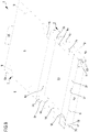
- the support 2 can comprise at least one base 2a and at least one lateral wall 4 emerging from an external perimeter of the base 2a; the at least one lateral wall delimits, opposite the base 2a, a free edge from which at least one abutment flap 2c can emerge: the abutment flap 2c is arranged facing the base 2a and is substantially extended parallel to the base 2a so as to define a kind of internal flange of the support 2.
- flap it is intended a band of material, for example made of sheet material, having a lengthwise extension along a longitudinal direction greater than a width-wise transverse extension.
- the flap can comprise a tongue of sheet material paper whose length is at least twice the extension width-wise and in which the length and the width are considerably greater than a third dimension defined by the thickness.
- Reference number 1 overall indicates a container for housing products, for example of food type.
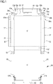
- the container 1 comprises at least one support 2 of sheet material, defining an internal volume 3, configured for housing products, e.g. pizzas, sandwiches or wraps.
- the support 2 has at least one base 2a with rectangular shape adapted to receive the product, starting from which at least one lateral wall 4 emerges which defines a free edge 6 and, together with the base 2a, delimits the internal volume 3.
- the lateral wall 4 perimetrically delimits the base 2a of the support 2 and is configured for emerging from the latter in a manner such to define a three-dimensional shape of the same support 2.
- the support 2 which has a quadrangular prismatic shape (lateral walls 4 that are for example flat and having rectangular shape).
- lateral walls 4 that are for example flat and having rectangular shape.
- the lateral wall 4 has a lower height than a longitudinal extension of the same lateral wall.
- the lateral wall 4 defines a lateral portion of reduced height to substantially define a tray, configured for housing products having a limited height.
- the support 2 has a first and a second lateral wall 4a, 4b that are adjacent to each other and configured for being engaged in a manner such to maintain the support 2 in a stable three-dimensional configuration.
- the first lateral wall 4a is extended along a predetermined extension direction between two longitudinal ends which, following the formation of the support 2, define respective corner portions.
- the second lateral wall 4b is also extended along a predetermined extension direction transversely, optionally orthogonally, with respect to the first lateral wall 4a, between respective longitudinal ends: the first and the second lateral wall 4a, 4b are therefore adjacent to each other at the respective end portions.
- the first and the second lateral wall 4a, 4b following the attainment of the stable three-dimensional configuration, are then engaged with each other to define an external edge of the support 2.
- the first lateral wall can comprise at least one air-vent opening 17 defined at at least one longitudinal end of same first lateral wall 4a, configured for allowing the communication between the internal volume 3 of the support 2 and the external environment.
- the air-vent opening 17 then allows expelling the air and/or the vapor present in the internal volume 3, in a manner such to maintain a constant humidity level within the container itself and consequently preserving the consistency and the taste of the food product.
- the air-vent opening 17 is delimited by an undercut portion configured for being constrained with a locking tongue 70 carried by a junction portion 18, in order to define the stable three-dimensional configuration of the support.
- the first lateral wall 4a can have at least two air-vent openings 17 respectively arranged at opposite longitudinal ends of the first lateral wall 4a. Each air-vent opening 17 is thus engageable with a respective locking tongue 70 carried by the second lateral wall 4b.
- the junction portion 18 comprises a superimposition tongue on which - for example following the attainment of a notch of the same superimposition tongue - a through opening is defined that is delimited by a perimeter edge of substantially circular shape; the locking tongue 70 is defined on the superimposition tongue and is configured to be constrained to the air passage opening 17.
- the locking tongue 70 is integrally joined to a section of the perimeter edge of the through opening and is movable via rotation with respect to the same edge between a position in which it faces the air-vent opening 17 (in such position the tongue 70 substantially lies parallel to the first lateral wall 4a), and a folded position in which the locking tongue 70 is constrained within the air-vent opening 17 in order to engage the first and the second lateral wall 4a, 4b.
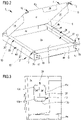
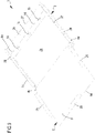
- the locking tongue 70 in the folded position ( figure 2 ), is configured for maintaining the lateral walls of the support in a three-dimensional configuration.
- the support 2 can have a third lateral wall 4c emerging from the base 2a starting from an external perimeter edge of the base 2a.
- the first, the second and the third lateral wall 4a, 4b, 4c emerge from the base 2a of the support along a same direction, in a manner such to delimit the internal volume 3.
- the first, the second and the third lateral wall 4a, 4b and 4c are then adjacent to each other, defining height-wise the triangular prismatic structure of the container.
- the third lateral wall 4c can stably carry the locking tongue 70 configured for being engaged with a respective air passage opening 17 defined on the first lateral wall 4a.
- the support 2 can further comprise a fourth lateral wall 4d emerging from the external perimeter edge of the base 2a: the first, the second, the third and the fourth lateral wall (4a, 4b, 4c, 4d) delimit height-wise the quadrangular prismatic structure of the support 2.
- the first and the third lateral wall 4a, 4c are opposite each other with respect to the base 2a of the support; in the same manner, the second and the fourth lateral wall 4b, 4d face each other and are opposite with respect to the base 2a of the support.
- first and the third wall 4a, 4c respectively define a front wall and a rear wall of the support, joined together by means of the second and of the fourth wall 4b, 4d which define respective lateral walls of the support.
- the ends of the first, second, third and fourth lateral walls 4a, 4b, 4c, 4d thus delimit the free edge 6.
- the support 2 comprises an abutment flap 2c emerging from at least one section of the free edge 6 so as to at least partly face the base 2a.
- the abutment flap 2c can be folded with respect to the section of free edge 6 with which it is engaged in order to define, in cooperation with the free edge 6 (and/or with an intermediate flap 26 described hereinbelow), a passage opening 5 configured for placing the internal volume 3 in communication with the external environment. It should be observed that the abutment flap 2c can emerge starting from at least one section of the free edge 6 defined by at least one between the first, the second, the third and the fourth lateral walls 4a, 4b, 4c and 4d. However, it is possible that the abutment flap 2c can emerge starting from a section of the free edge 6 defined by one or more lateral walls 4.
- the support 2 can comprise an abutment flap 2c emerging from the free edge section 6 defined at the first wall 4a and facing the third wall 4c.
- the support 2 can comprise a first abutment flap emerging from the second wall 4c and a second abutment flap emerging from the fourth wall 4d: the first and the second abutment flap are directed towards each other.
- a plurality of abutment flaps 2c each of which emerging from a respective lateral wall 4.
- each abutment flap 2c is extended for the entire longitudinal extension of the lateral wall 4 with which it is engaged. In other words, each abutment flap 2c is extended for the entire section of the free edge 6 defined by the lateral wall with which said flap 2c is directly carried.
- the abutment flap 2c has a limited extension along a direction facing the internal volume 3 of the support 2, in a manner such to obstruct the access to the internal volume 3 to a limited extent and consequently maximize the extension of the through opening 5: the abutment flap 2c then allows an easy insertion of the food product in the internal volume 3.
- the extension of the abutment flap 2c along a direction entering the internal volume 3 can be comprised between 2 cm and 10 cm, while the ratio between the extension of the abutment flap 2c along the direction entering the internal volume 3 and the extension of the lateral wall with which it is engaged can be comprised between 0.06 and 0.3.
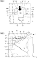
- the support 2 can also comprise a separator 14 extended in the internal volume 3 interposed between the abutment flap 2c and the base 2a of the same support 2, configured for dividing a central zone of the support adapted to receive the product, from a peripheral zone of the support at which the abutment flap 2c is defined.
- the separator 14 is integrally joined to the abutment flap 2c and folded relative to the latter along an end edge 6a opposite the free edge 6.
- the separator 14 can be engaged with the base 2a via mechanical interference or via gluing.
- the separator 14 is extended width-wise between the end edge 6a and the base 2a.
- the separator 14 can be extended transversely, optionally orthogonally, to the abutment flap 2a with which it is engaged, thus having equal height with respect to each lateral wall 4.
- the separator 14 is extended lengthwise substantially for the entire extension of the abutment flap 2c, substantially defining a channel delimited by the support 14, by the abutment flap 2c and by the lateral wall 4 with which the latter is integrally joined.
- the separator 14 is also configured for dividing the internal volume 3 in a first sub-chamber 40 configured for receiving the product and in a second sub-chamber 45 delimited by the channel and arranged at a perimeter zone of the support 2.
- the channel faces the air-vent opening 17, in a manner such to allow the air and/or vapor present within the second sub-chamber 45 to be expelled from the support through the air-vent opening 17.
- the separator 14 can then be interposed between the lateral wall 4 of the support on which the air-vent opening 17 is defined and the central zone of the support adapted to receive the product.
- the separator 14 can comprise at least one through access 16 configured for placing in fluid communication the first and the second sub-chamber 40, 45: by means of the through access 16, the air and/or the vapor present within the first sub-chamber 40 are conveyed within the second sub-chamber 45 and expelled through the air-vent opening 17.
- the through access 16 can have a circular or polygonal conformation, with dimensions comprised between 20% and 90% of the width of the same separator 14, in a manner such to allow an effective transfer of fluid between the first and the second sub-chambers 40, 45 without compromising the structural strength of the separator 14.
- Each through access 16 is offset with respect to an air access opening 17, in a manner such to prevent a user from inserting a finger and/or a tool through the through access 16 and the air access opening 17 to contaminate the product placed in the central zone of the support.
- the separator 14 can further comprise a plurality of through accesses 16 that are equidistant from each and distributed for the entire length of the same separator 14, configured for maximizing the transfer of fluid between the first and the second sub-chamber 40, 45.
- the support 2 can comprise a single separator 14 integrally joined to the first lateral wall 4a; alternatively, the support 2 can comprise a plurality of separators 14, respectively integrally joined to the first and to the second abutment flap 2c.
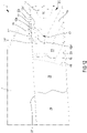
- the support 2 can further comprise at least one intermediate flap 26 emerging from at least one section of the free edge 6 of the support 2 adjacent to the support flap 2c.
- the intermediate flap 26 faces the base 2a of the support, in a manner such to define a portion folded along the section of free edge 6 with which it is engaged and perimetrically delimiting the through opening 5.
- the intermediate flap 26 has a rectangular shape extended for the entire the free end section defined by the lateral wall with which it is engaged.
- the intermediate flap 26 has a limited extension along a direction facing the internal volume 3 of the support 2, in a manner such to maximize the extension of the through opening 5 and allow an easy insertion of the food product in the internal volume 3.
- the extension of the intermediate flap 26 along a direction entering the internal volume 3 can be comprised between 2 cm and 10 cm.
- the ratio between the extension of the intermediate flap 26 along the direction entering the internal volume 3 and the extension of the lateral wall with which it is engaged can be comprised between 0.06 and 0.3.
- the intermediate flap 26 is substantially identical to the abutment flap 2c. As is visible in the enclosed figures, the intermediate flap 26 is defined adjacent to the abutment flap 2c, being superimposed on the abutment flap 2c at a longitudinal end of the latter.
- the intermediate flap 26, in the closed condition of the container 1, can be then interposed between the same abutment flap 2c and the closure system 7.
- the intermediate flap 26 can further have a through opening 28 with closed profile, arranged, at least in the closed condition of the closure system 7, facing the abutment flap 2c.
- the through opening 28 can be defined at a longitudinal end of the intermediate flap 26 superimposed on the abutment flap 2c.
- the through opening 28 is configured for allowing a first coupling portion 12 carried by the closure system to reach a second coupling portion 13 defined at the longitudinal end of the abutment flap 2c arranged within the intermediate flap 26.
- the intermediate flap 26 can comprise a first and the second intermediate flap 26', 26" ( figure 2 , 11 and 12 ) emerging respectively from sections of the free edge 6 defined by the second and by the fourth lateral wall 4b, 4d; first and second intermediate flaps 26', 26" are both superimposed on an abutment flap 2c defined at the first wall 4a.
- the support 2 can comprise a single intermediate flap 26 integrally joined to the first wall 4a, which is superimposed on respective terminal portions of the abutment flaps 2c carried by the second and by the fourth lateral wall 4b, 4d.
- the support 2 can further comprise a slit 27 made following the definition of a notch on the same intermediate flap 26 and/or on the abutment flap 2c, configured for allowing the insertion of at least one connection tongue 25 within the internal volume 3 of the support 2.
- the slit 27 is defined in proximity to the free edge 6 and is extended parallel to the latter for a size comprised between 5% and 80% of the longitudinal extension from terminal portions of the lateral wall which defines the same free edge 6.
- the slit 27 is extended for most of the longitudinal extension of the intermediate flap 26 on which it is defined.
- the slit 27 is extended for a limited section of the intermediate edge 27 comprised between 10% and 40% of the longitudinal extension of the intermediate flap 26.
- the support 2 is made of sheet material and obtained for example via folding.
- the support 2 is made of sheet material paper (paper or cardboard); in particular, the sheet material used has a basis weight comprised between 100 and 500 g/m2, in particular comprised between 200 and 400 g/m 2 .
- the container 1 comprises a closure system 7, also of sheet material, engaged at at least one section of the free edge 6 and movable, in particular via rotation, with respect to the support 2.
- the closure system 7 is configured for defining at least one closed condition in which the same closure system 7 prevents the communication between the internal volume 3 of the support 2 and the external environment and an open condition in which it allows a user to access the internal volume 3 of the support 2 (see for example figures 2 , 9 , 10 and 12 ).
- the system 7 substantially represents a cover adapted to cooperate with the support 2 so as to manage the access to the internal volume 3.
- the closure system 7 is, in a non-limiting manner, integrally joined at the free end section 6 defined by the third wall 4c, being movable via rotation around the latter at least between the open and closed conditions.
- a closure system 7 that is separate and completely separable from the free edge 6, in fact defining a cover removably engageable with the support 2.
- the closure system 7 comprises at least one closure panel 8 of sheet material and engaged with at least one section of the free edge 6.
- the closure panel 8 has a conformation that is counter-shaped with respect to the free edge 6 in a manner such to allow, in the closed condition of the closure system 7, to entirely obstruct the passage opening 5 and prevent the access to the internal volume 3.
- the closure panel 8 in the closed condition of the closure system 7, is at least partly in contact with the abutment flap 2c and with the intermediate flap 26.
- the closure panel 8 can also have at least one connection tongue 25 configured for being inserted, in the closed condition of the system 7, within the volume 3 of the support 2.
- the connection tongue 25 is integrally joined to the closure panel 8 and emerges from the latter starting from an external perimeter edge 8a delimiting the closure panel 8.
- the connection tongue 25 substantially represents an extension of the closure panel 8 adapted to be inserted, in the closed condition of the system 7, within the slit 27 of each intermediate flap 26.
- the connection tongue 25 is defined from a flat body of sheet material having, as a non-limiting example, rectangular shape. In the closed condition of the closure system 7, the connection tongue 25 directly faces, in particular contacts, a part of a lateral wall 4 of the support 2, extended parallel to the latter.
- connection tongue 25 is also movable via rotation with respect to the closure panel 8 around a section of the external perimeter edge 8a.
- the connection tongue 25, in the closed condition of the closure system 7, is configured for defining, according to a transverse section and in cooperation with the closure panel 8, a substantially "L" shape: in such condition the connection tongue 25 is substantially extended parallel to a lateral wall 4 of the support 2.
- the closure panel 8 can have three connection portions 25, each of which, in the closed condition of the closure system 7, is respectively insertingly within a slit 27 defined on the first and on the second intermediate flap 26', 26" and on the abutment flap 2c.
- the closure panel 8 can have a single connection portion 25 insertable within a respective slit 27 defined on the intermediate flap 26 integrally joined to the first lateral wall 4a.
- the closure system 7 is at least partly made, in particular entirely, of sheet material paper (paper, cardboard or corrugated cardboard); the sheet material used has a basis weight comprised between 100 and 500 g/m2.
- the sheet material paper used for attaining the closure system 7 is equivalent to the sheet material used for attaining the support 2, in particular they are both obtained starting from only a single sheet of paper material.
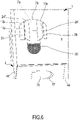
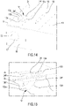
- the container 1 comprises at least one first coupling portion 12, carried by the closure system 7, and at least one second coupling portion 13 defined on at least one abutment flap 2c.
- the first coupling portion 12 is configured for being stably engaged with an undercut portion 13b of the second coupling portion 13 in a manner such to define a locking condition.
- the first coupling portion 12 is engageable with the second coupling portion 13 following the arrangement of the closure system 7 in contact with the abutment flap 2c and with the intermediate flap 26, in a manner such to arrange the same first coupling portion 12 in superimposition on the second coupling portion 13 and on the display opening 28.
- the attainment of the engagement between the first and second coupling portions 12, 13 is only reached following the alignment of the latter along a direction orthogonal to the base 2a of the support 2.
- the first coupling portion 12 is attained on the closure system 7 following the definition on the latter of a notch adapted to define a through seat 7a delimited by a perimeter edge with closed profile which is arranged within the external perimeter edge 8a of the closure portion. Consequently, the first coupling portion 12 is defined arranged within the through seat 7a and within the external perimeter edge 8a. However, it is possible to attain a first coupling portion 12 emerging starting from the external perimeter edge 8a of the closure portion 8.
- the first coupling portion 12 comprises a central body 12a and a base body 12c integrally joined to the central body by means of a folding edge 22: the central body 12a is movable with respect to the base body 12c around the folding edge 22.
- the central body 12a and in general the first coupling portion 12, can thus be movable around the folding edge 22 at least between a first and a second operating position.
- the first coupling portion 12 In the first operating position, the first coupling portion 12 is disengaged from the second coupling portion 13, at least partly facing a through pocket 13a of the second coupling portion 13.
- the first coupling portion 12 In the second operating position, the first coupling portion 12 is arranged in the internal volume 3 of the support, engaging with an undercut portion 13b of the same second coupling portion 13.
- the central body 12a has a surface size smaller than a passage area defined by the through pocket 13a of the second coupling portion 13, which is sufficiently small in order to allow the same central body 12a to insertingly pass through the through pocket 13a, i.e. allow the passage of the first coupling portion 12 from the first to the second operating position.
- the first coupling portion 12 can further comprise at least one tab 12b emerging from the central body 12a starting from a folding edge 21.
- the tab 12b can be movable via rotation around the folding edge 21 from a position in which it lies parallel to the central body 12a, to a position in which it is arranged transverse to the latter, in which it is configured for being engaged with the undercut portion 13a of the second coupling portion 13.
- the tab 12b lies parallel to the central body 12a at least in the first operating position of the first coupling portion 12; vice versa, in the second operating position of the first coupling portion 12, the tab 12b defines, in cooperation with the central body 12a, a portion folded having a substantially "L" shape.
- the tab 12b is, in the closed condition of the closure system 7 and in the first operating position of the first coupling portion 12, facing the undercut portion 13b of the second coupling portion 13.
- the tab 12b during the passage between the first and the second operating position, is configured for being folded with respect to the central body 12a in order to allow the insertion of at least part of the latter and of the tab 12b within the through pocket 13a of the second coupling portion 13.
- the first coupling portion 12 in the second operating position of the latter is entirely arranged in the internal volume 3 of the support 2 and in particular within the second sub-chamber 45.
- the tab 12b then defines a respective undercut portion of the first coupling portion which, in the second operating position, faces the undercut portion 13b of the second coupling portion 13 and is configured for being engaged with the latter in order to define the locking condition.
- the tab 12b can comprise a first and a second tab 12b', 12b" integrally joined to the central body 12a at respective folding edges 21 that are opposite each other.
- the first and second tabs 12b', 12b" are then configured, during the passage of the first coupling portion 12 from the first to the second operating position, in order to be folded with respect to the central body 12a in a manner such to define a substantially "C” or "U” shape having a concavity facing the closure system 7.
- the container 1 can comprise two first coupling portions 12 defined at respective corner portions of the closure panel 8 arranged on the opposite side with respect to the free edge 6.
- the first coupling portions 12 are configured for being engaged with respective second coupling portions 13 defined on the abutment flap 2c directly connected to the first lateral wall 4a.
- the container 1 can comprise a pair of first coupling portions 12 thereof defined along a first perimeter portion of the closure panel 8, respectively engageable with second coupling portions 13 defined on the first abutment flap; the container 1 can also comprise a second pair of first coupling portions 12 defined along a second perimeter portion of the closure panel 8, opposite the first perimeter portion and configured for being engaged with respective second coupling portions 13 defined on the second abutment flap.
- the pairs of first coupling portions are arranged at a predetermined distance from each other, configured for effectively preventing a user from lifting the closure panel 8.
- the distance between a pair of first coupling portions 12 is comprised between 15 cm and 30 cm.
- the container 1 comprises at least one second coupling portion 13 defined on the abutment flap 2c.
- the second coupling portion 13 comprises a through pocket 13a delimited by a perimeter edge and at least partially by a contrast portion 30.
- the through pocket 13a defines an opening configured for allowing the insertion of the first coupling portion 12 within the internal volume 3 of the container.
- the through pocket 13a is at least partly delimited by an undercut portion 13b which is configured for engaging the tabs 12b of the first coupling portion 12.
- the undercut portion 13b is configured in order to allow, during the passage of the first coupling portion 12 from the first to the second operating position, intercepting the tabs 12b and allowing the folding thereof with respect to the central body 12a.
- the passage section delimited by the undercut portion 13b is greater than a surface size of the central body 12a, but smaller than the sum of respective surface sizes of the central body 12a and of the tabs 12b.
- the passage section delimited by the undercut portion 13b thus sized allows the tabs 12b to be intercepted by the same undercut portion 13b, allowing the folding thereof on the central body 12a and the consequent engagement with the latter.
- the second coupling portion 13 can also comprise at least one locking tab 24 emerging from the undercut portion 13b starting from a respective folding edge 13c, configured for at least partially obstructing the through pocket 13a in the second operating position of the first coupling portion.
- the locking tab 24 is movable via rotation around the folding edge 13c at least between a flat position and a tilted position, by means of the thrust of the first coupling portion 12 exerted on the same locking tab 24 during the passage from the first to the second operating position.
- the locking tab 24 in the first closed condition of the closure system 7 and at least in the first operating position of the first coupling portion 12, the locking tab 24 is in the flat position, in which substantially it lies parallel to the abutment flap 2c.
- the locking tab 24 is in the tilted position, in which it lies transverse to the abutment flap 2c. In the latter position, the locking tab 24 is folded with respect to the undercut portion 13b of the second coupling portion 13 at least partly in the internal volume 3 of the support 2, in a manner such to at least partially allow the insertion of the first coupling portion 12 through the through pocket 13a and be stably constrained with the tabs 12b.
- the locking tab 24, in the tilted position is substantially interposed between the through pocket 13a of the second coupling portion 13 and at least one part of the first coupling portion 23 arranged in the internal volume 3 of the support 2.
- the locking tab 24 in the tilted position, engages the tab 12b of the first coupling portion and prevents the latter from being moved towards a direction exiting the through pocket 13a.
- the locking tab 24 can also comprise a first and a second locking tab 24', 24" respectively engaged with opposite portions of the perimeter edge of the through pocket 13a.
- the first and second locking tabs 24', 24" are engaged with sections of the perimeter edge that are opposite each other, both configured for at least partially obstructing the through pocket 13a.
- the first and second locking tabs are engaged with the perimeter edge at respective folding edges, around which they are movable via rotation between the flat position in which they are parallel to and abutted against each other ( figure 3 ), and the tilted position in which they are relatively tilted and spaced from each other ( figure 6 ).
- first and second locking tabs 24', 24" are also configured for being constrained respectively with the first and second locking tabs 12b', 12b", preventing the exit of the latter from the through pocket 13a.
- the locking tabs 24 thus prevent a user from accessing the first coupling portion 12 and disengaging it from the second coupling portion 13.
- the container 1 can comprise a pair of second coupling portions 13 defined at corner portions of the abutment flap 2c defined at the second and of the fourth lateral wall 4c, 4d. Furthermore, the container 1 comprises a first pair of second coupling portions 13 defined along the first abutment flap, as well as a second pair of second coupling portions 13 defined on the second abutment flap; the pairs of second coupling portions 13 are arranged at a predetermined distance from each other, configured for effectively preventing a user from lifting the closure panel 8. In particular, the distance between a pair of second coupling portions is comprised between 15 cm and 30 cm.
- first and second coupling portions 12, 13, in the second operating position of the first coupling portion 12, are configured for defining a locking condition of the container in which said first and second coupling portions 12, 13 are stably engaged with each other in order to oppose the passage of the closure system 7 from the closed condition to the open one.
- the first coupling portion 12 comprises a removable portion configured for being separated from the closure system 7 during a first open condition of the container following the locking condition in order to provide evidence of a tampering of the container 1.
- the first coupling portion 12 is carried by the closure system 7; in detail, the first coupling portion 12 is engaged with the closure system 7 by means of a weakening portion 23 configured for being broken, following the definition of the locking condition, during the passage of the closure system 7 from the first closed condition to the first open condition.
- the removable portion defined by at least one part of the first coupling portion 12 is integrally joined to the closure system 7 by means of a connection flap having a plurality of notches adapted to allow the tearing (optionally facilitated) of the connection flap: the notched connection flap defines the weakening portion adapted to connect the removable portion (the first coupling portion 12) to the closure system 7.
- the removable portion defined by said first coupling portion 12 is engaged with the closure system 7 only by means of said weakening portion 23; the weakening portion 23 is configured for allowing a facilitated tearing of the first coupling portion 12 in a manner such that, even following a slight stress of the first coupling portion 12, the same weakening portion 23 can be broken and allow the separation of the first coupling portion 12, thus giving proof of an attempted tampering of the container 1.
- the first coupling portion 12 can be at least partly engaged with the closure system 7 at a plurality of weakening portions 23, the latter configured for being broken following the verification of a first open condition of the container in a manner such to define the removable portion.
- first coupling portion 12 is only engaged with the closure system 7 at the weakening portions 23, entirely defining the removable portion.
- the entire first coupling portion 12 is configured for being separated from the closure system 7, giving proof to a user of tampering of the container.
- a first coupling portion 12 comprising a base body 12c engaged with the closure system 7 at the perimeter edge of the through seat 7a, by means of the weakening portion 23.
- the central body 12a is engaged with the base body 12c by means of a folding edge 22 that is separate and spaced from the weakening portions 23: the folding edge 22 allows the rotation of the central body 12a in an independent manner with respect to the base body 12c.
- arranging a folding edge 22 spaced from the weakening portions 23 allows preventing the accidental breakage of the latter in step of folding of the first coupling portion 12 engaging with the second coupling portion 13.
- the base body 12c represents the element of the first coupling portion 12 connected to the closure system 7 by means of one or more weakened portions; the central body 12a, together with the at least one tab 12b, are integrally joined to the base body 12c and are foldable within the volume 3 of the container in order to define the locking condition.
- the base body 12c is configured for remaining, both in the first and in the second operating position of the first coupling portion 12, outside the internal volume 3 while the central body 12a and the at least one tab 12b are foldable with respect to said base body 12c during the passage from the first to the second operating position ( figure 4 ) up to reaching a position inside the volume 3 ( figure 5 ).
- the at least one tab 12b is foldable with respect to the central body 12a around the folding edge 21 extended transversely to the folding edge 22 of the central body 12a, separate and spaced from the same folding edge 22.
- the step of folding of the first coupling portion 12 within the internal volume 3 is in fact visible, during which the tabs 12b', 12b" are folded around the edge 21 in order to allow the passage of the central body 12a and of the same tabs from the through pocket 13a; in such step, the central body 12a and the tabs are also folded with respect to the base body 12c around the folding edge 22.
- the tabs 12b are configured for being extended and stably engaged with the undercut portion 13b delimiting the through pocket 13a in order to lock the first coupling portion 12 within the volume 3.
- the first coupling portion 12 is configured for being separated (due to the presence of the weakened portion 23) from the same closure system 7 and be deposited within the second sub-chamber 45.
- the first coupling portion 12 thus removed can give evidence of a tampering of the container that took place, without coming into contact with the first sub-chamber 40 and in particular, with the food product contained therein.
- the second coupling portion 13 can further comprise a contrast portion 30 defined on the abutment flap 2c and/or on the intermediate flap 26 and arranged, during a first closed condition 7 of the container, below the exposed surface of the removable portion, in particular below the base body 12c.
- the contrast portion 30 defines an indicator visible through the through seat 7a of the closure system 7, configured for giving evidence of tampering of the container that occurred following the first open condition of the closure system 7.
- the contrast portion 30 can also comprise a signaling surface that is visibly different with respect to the abutment flap 2c and/or to the intermediate flap 26, configured for rendering the occurrence of the first open condition of the container even more evident to a user.
- the absence of the first removable portion 12 torn following the first open condition of the container 1 allows uncovering and rendering visible the contrast portion, which can visually signal (indicate) the absence of the first coupling portion 12, thus giving a user the possibility to quickly notice an attempt of tampering of the container 1.
- At least one between the support 2 and the closure system 7 can comprise at least one tear portion 9, 19 configured for allowing the breakage of said support 2 and/or closure system 7 during an attempt to open the container 1 itself when this is arranged in the locking condition.
- the support 2 comprising at least one tear portion 19 defined on at least the lateral wall of the support 2, in particular defined on the second and fourth lateral wall 4b, 4d.
- at least one of said lateral walls of the support can comprise a plurality of tear portions 19 each defined by one or more aligned notches adapted to define a weakened portion of the lateral wall.
- Such notches can for example be extended starting from the base 2a up to at the free edge 6 ( figure 6 ).
- each notch 19 can connect the base 2a with the slit 27 of the support adapted to receive the tongue 25 of the closure system.
- Such notches 19 are spaced and separated from the second coupling portion defined on the support 2 itself: the second coupling portions 13 are in fact placed at corner portions while the notches are arranged on the lateral walls of the support at a distance from the corner portions.
- the closure system 7 comprises, in a non-limiting manner, at least one tear portion 9, separate and spaced from the removable portion (i.e. separate and spaced from each first coupling portion): each tear portion 9 of the closure system 7 comprises at least one notch, optionally a plurality of notches aligned along a predetermined trajectory and placed one after the other, defined on the closure portion 8 and extended substantially starting from the perimeter edge of said closure portion.
- the closure system 7 can comprise a plurality of tear portions 9 configured for allowing the breakage of the closure system 7 itself during an attempt of access of a user in the locking condition of the container. Illustrated in the enclosed figures, in a non-limiting manner, is a closure system 7 comprising four tear portions 9 arranged, in pairs, at opposite sides of the closure system 7.
- each tear portion 9, 19 is positioned at a distance from the first and second coupling portions 12, 13, in particular at possible opening/access zones of the container.
- the tear portions 9, 19 are capable of giving evidence of an attempt of tampering of the container caused by an attempt to access inside the internal volume of the container without carrying out the normal opening of the same.
- Also forming the object of the present invention is a process for attaining a container 1 in accordance with the above-reported description and/or with any one of the enclosed claims.
- the process provides for the arrangement of the support 2 which, as described above, is made of sheet material, optionally paper.
- the step provides for the arrangement of at least one first blank 50 of flat sheet material, comprising at least one central sheet 51 having a substantially quadrilateral, optionally square shape, at which at least one first lateral sheet 52 integrally joined to the central sheet 51 is engaged and emerging from the latter starting from the perimeter edge.
- the blank comprises a plurality of first lateral sheets 52 emerging for an entire perimeter edge of the central sheet 51.
- the process can also comprise a step of folding of each first lateral sheet 52 with respect to the central sheet 51 in a manner such that the latter defines the base 2a of the support 2, while the first lateral sheets 52 define the first, the second, the third and the fourth lateral wall 4a, 4b, 4c, 4d of the support.
- the first blank 50 can comprise at least one junction sheet 56 integrally joined to the first lateral sheets 52 defining the second and the fourth lateral wall 4b, 4d, at the longitudinal ends of the latter.
- the process can comprise a step of notching the junction sheet 56 in a manner such to make an opening 56a defining at least one tongue 56b.
- the step of notch of the junction sheet allows defining the locking tongue 70.
- the process further comprises a step of notching the first lateral sheet 52 defining the first lateral wall 4a and/or the first lateral sheet 52 defining the third lateral wall 4c, in a manner such to make at least one terminal opening 52a defining the air-vent opening 17.
- the process provides for the definition of the terminal opening 52a on said first lateral sheets 52 at the respective longitudinal ends adjacent to a tongue 56b of the terminal sheet 56.
- the process can also comprise a step of folding the terminal sheet 56 superimposed on a first lateral sheet 52 adjacent to the latter, as well as a step of engaging the tongue 56a within the terminal openings 52a, in a manner such to reach the stable three-dimensional configuration of the support.
- the blank 50 can also comprise a second lateral sheet 53 integrally joined to the first lateral sheet 52 on the side opposite the central sheet 51: the first lateral sheet 52 is thus interposed between said the central sheet 51 and the second lateral sheet 53.
- the latter is integrally joined to the second sheet 52 defining the first lateral wall 4a.
- the latter can comprise a plurality of third leaves 53, each of which integrally joined to the lateral sheets 52 defining the second and the fourth lateral wall 4b, 4d.
- the process can also comprise the attainment of a through notch 53a on the second lateral sheet 53 in a manner such to define the second coupling portion 13 and, in particular, the first and second locking tabs 24', 24".
- the process can further comprise a step of folding of each second sheet 53 with respect to the second lateral sheet with which they are engaged, in a manner such that the second lateral sheet 53 defines the abutment flap 2c of the support 2.
- the blank 50 can also comprise a third lateral sheet 55 integrally joined to a first lateral sheet 52 with which the second lateral sheet 53 is not engaged: the first lateral sheet 52 is then interposed between the central sheet 51 and the third lateral sheet 55.
- the process can further comprise a step of notching the fourth lateral sheet 55 in a manner such to make a separator 57 defining the slit 27.
- Such notching step in accordance with the first embodiment of the container shown in figure 1 , can also be made on the second lateral sheet 52 interposed between the central sheet 51 and the second lateral sheet 53.
- the process can also comprise a step of notching the third sheet 55, making through openings 55a, which define the display openings 28. It should be observed that the process can provide for a further step of folding the third lateral sheet 55 with respect to the first sheet 52 with which it is engaged in a manner such to define the intermediate flap 26.
- the process comprises a perimeter blank 54 in turn comprising a first auxiliary sheet 54a integrally joined to the third sheet 53 on the side opposite the second sheet 52.
- the blank 54 can further comprise a second auxiliary sheet 54b integrally joined to the first auxiliary sheet on the side opposite the third sheet 53.
- the first auxiliary sheet 54a can be interposed between the third sheet 53 and the second auxiliary sheet 54b.
- the process can then comprise a step of folding the first auxiliary sheet 54a with respect to the third sheet 53 in a manner such to define the separator 14, as well as a step of folding of the second auxiliary sheet 54b with respect to the first auxiliary sheet 51a.
- the process can then provide for a step of engaging the same second auxiliary sheet 54b with the central sheet 51 of the first blank, for example by means of gluing or mechanical interference, defining the first and the second sub-chamber 40,45.
- the process can also comprise a step of notching executed on the first auxiliary sheet 54a in a manner such to make at least one through opening 154 defining the through access 16 of the separator 14.
- such notching step can provide for defining a plurality of through openings 154 that are separate and spaced from each other, each of which defining a through access 16.
- the process can further comprise the arrangement of a second blank 60 of sheet material, associable with the first blank 50.
- a second blank 60 of sheet material associable with the first blank 50. It should be observed that in the enclosed figures the second blank 60 is shown integrally joined to the first blank 50 to define a single flat blank. Nevertheless, it may be possible that the second blank 60 be separate and spaced from the first blank 50, in a manner such to substantially define a cover configured for being engaged with the latter.
- the second blank 60 can be integrally joined to a second lateral sheet 52 defining the third lateral wall 4c of the support, in a manner such that said second lateral sheet 52 is interposed between a central sheet 61 of the second blank 60 and the central sheet 51 of the first blank 50.
- the second blank 60 then comprises the central sheet 61 and at least one peripheral sheet 62 integrally joined to the central sheet 61.
- the process comprises a step of folding of each peripheral sheet 62 with respect to the central sheet 61 in a manner such to define the connection tongue 25.
- the process can provide for a step of folding each peripheral sheet 62 with respect to the central sheet 61 of the second blank, in a manner such to allow the insertion of the same peripheral sheet within the separator 57.
- the process comprises a step of notching the central sheet 61 of the second blank 60 in a manner such to make at least one notch 61b defining the first coupling portion 12.
- the process can provide for the execution of the latter step of notching the central sheet 61 of the second blank 60 in a manner such to make a plurality of first coupling portions 12.
- the process can comprise a step of arranging at least one weakened section 61a defining the weakening sections 23 of the removable portion.
- the process provides for making a plurality of weakening sections at each notch 61a, defining a respective removable portion.
- the process can also comprise a step of folding of the central sheet 61 of the second blank with respect to the first lateral sheet 52 with which it is engaged, in a manner such to allow the superimposition of the central sheets 51, 61 respectively of the first and of the second blank 50, 60.
- the process provides for a step of inserting each peripheral sheet within a respective separator 57.
- the latter step in cooperation with the step of folding of the central sheet 61 of the second blank, allows achieving the closed condition of the closure system 7.
- the present invention also relates to a method for closing a container 1 in accordance with the above-reported description and/or with any one of the enclosed claims.
- the method for closing the container 1 provides for arranging a container 1 in accordance with any one of the above-described embodiments.
- the method for closing the container 1 comprises a step of arranging the closure system 7 in the closed condition of the closure system 7.
- the closing method also provides for pushing, for example by means of a finger of a user, the first coupling portion 12 through the through pocket 13a of the second coupling portion 13, determining the rotation of the central body 13a with respect to the base body 13c, as well as the rotation of the first and of the second tab 12b', 12b" on the central body 13a.
- Such step then provides for inserting the second coupling portion 12 thus folded in the internal volume 3 of the support engaging the undercut portion 13b of the second coupling portion 13.
- the step of pushing the first coupling portion 12 through the through pocket 13a of the second coupling portion 13 further determines the movement of the first and of the second locking tab 24', 24" with respect to the abutment flap 2c towards a direction entering the through pocket 13a.
- the closing method can then provide for arranging the first and the second tab 12b', 12b" below the first and second locking tabs 24', 24" and engaging with the latter, in a manner such to reach the locking condition.
- the closing method furthermore provides for repeating the execution of the steps of insertingly pushing the first coupling portion 12 within the through pocket 13a of the second coupling portion 13, as well as of the step of engaging the same first coupling portion with the first and second locking tabs 24', 24".
Landscapes
- Engineering & Computer Science (AREA)
- Mechanical Engineering (AREA)
- Packages (AREA)
- Closures For Containers (AREA)
Abstract
Description
- The object of the present invention is a container for housing products, for example of food type. In particular, the container, object of the present invention, can be of the type to give evidence of tampering and be applied in the field of packaging food products, e.g. for pizzas, in order to ensure the supply of intact products, which are not all altered. The object of the present invention is also a process for attaining said container as well as a method for closing the same.
- As is known, containers lacking tampering-evidence mechanisms are available on the market. For example, the patent application No.
US 5.240.176A shows a container for transporting trash having a locking system adapted to prevent the opening of the container while the patent application No.DE 20 2009 003994 U1 shows a container for pizza, it too lacking a tampering-evidence mechanism. - The containers today attained with tampering-evidence mechanisms are mainly used in the pharmaceutical sector in order to indicate the danger of a possible tampering or substitution of the product, hence ensuring product integrity for the consumer. Nevertheless it is indicated that such containers have a structurally complex closure mechanism, hard to reinforce in brief time periods.
- One type of tamper-evident container is described in the patent application No.
BE410524A - The Applicant has detected that such container has important limitations. In fact it should be observed that such container does not allow giving clear evidence of tampering in the case that the container has been previously opened. In fact, the user perceives the integrity of the container only based on the perception of the resistance exerted by the first coupling portion on the second coupling portion, without having visual evidence of tampering. Furthermore, such container attains a complex engagement between the first and second coupling portions, which cannot be executed in an automated manner, nor in a quick manner by an operator.
- A second example of a tamper-evident container is described in the patent application No.
US 2011/180537 A1 . Such container comprises a store reclosable following the engagement between a first coupling portion carried by a closure system and a second coupling portion carried by the store. The first coupling portion comprises a tongue engaged with the closure system by means of a weakening portion and configured for being engaged within a single opening made on a panel carried by the store. In particular, the opening of the second coupling portion is entirely counter-shaped with respect to the first coupling portion and is configured for being aligned with the latter, in a manner such to allow the insertion thereof and define a closed condition of the container. Following the opening of the container, the first coupling portion is thus configured for being separated from the closure system, giving evidence of a first opening of the container. - The Applicant has detected that the container described in the United States patent application No.
US 2011/180537 A does not allow defining an effective closure, capable of giving correct evidence of tampering of the container. Indeed, the Applicant has detected that the first coupling portion is easily extractable from the opening made on the panel engaged with the store without said first coupling portion being separated from the closure system. - Even if the above-described known containers are used today, the Applicant has detected that such containers are not free of limitations and drawbacks, and therefore can be improved with regard to several aspects.
- Object of the present invention is therefore that of substantially resolving at least one of the drawbacks and/or limitations of the preceding solutions.
- A first objective of the present invention is to provide a container which can effectively give evidence of tampering following a first opening attempt of the same. A further object of the present invention is that of providing a tamper-evident container that can be easily reinforced, both in an automated manner and by an authorized operator. Another object of the present invention is to provide a container that is simple and quick to manufacture, which allows minimizing the consumption of material and consequently the costs of production and transport. A further object of the present invention is to provide a container that is flexible in use which can be effectively employed on different types of containers of sheet material. Another object of the present invention is to provide a container capable of preventing the contact between one or more products housed in the container itself in the event in which the latter is closed by a user.
- These objects and still others, which will be clearer from the following description, are substantially achieved by a container, a process for making the same and a method for closing the container in accordance with that expressed in one or more of the enclosed claims and/or of the following aspects.
- In a first aspect, a container (1) is provided for housing at least one product, e.g. of food type, said container (1) comprising:
- a support (2) defining an internal volume (3) configured for housing at least one product, said support (2) comprising:
- ∘ at least one base (2a),
- ∘ at least one lateral wall (4) emerging from the base (2a) and delimiting, in cooperation with said base (2a), the internal volume (3), in which said at least one lateral wall (4) defines, opposite the base (2a), a free edge (6),
- ∘ at least one abutment flap (2c) emerging from at least one section of the free edge (6) and at least partly facing the base (2a), in which said at least one abutment flap (2c) at least partly delimits a passage opening (5) configured for placing in communication the internal volume (3) with the external environment,
- a closure system (7) movable with respect to the support (2) at least between:
- ∘ a closed condition of the container in which the closure system (7) is configured for preventing the communication between the internal volume (3) of the support (2) and the external environment, and
- ∘ an open condition of the container in which the closure system (7) is configured for allowing the communication between the internal volume (3) and the external environment.
- In one aspect according to the preceding aspect the closure system, in the closed condition, is at least partly abutted against the abutment flap (2c). In one aspect according to any one of the preceding aspects the closure system (7), in the open condition of the container is at least partly spaced from the abutment flap (2c). In one aspect according to any one of the preceding aspects the container is for housing one or more pizzas.
- In one aspect according to any one of the preceding aspects the container comprises:
- at least one first coupling portion (12) carried by the closure system (7),
- at least one second coupling portion (13) defined on the at least one abutment flap (2c).
- In one aspect according to any one of the preceding aspects the second coupling portion (13) comprises at least one through pocket (13a) at least partly delimited by at least one undercut portion (13b).
- In one aspect according to any one of the preceding aspects the first coupling portion (12), at least during a first closed condition of the container, is movable at least between:
- a first operating position in which the first coupling portion (12) is disengaged from the second coupling portion (13),
- a second operating position in which at least part of the first coupling portion (12) passes through the through pocket (13a) and is arranged in the internal volume (3), engaging the undercut portion (13b).
- In one aspect according to the preceding aspect the first coupling portion (12), in the first operating position, is at least partly facing the through pocket (13a) of the second coupling portion (13).
- In one aspect according to any one of the preceding aspects the first and second coupling portions (12, 13), in the second operating position of the first coupling portion (12), are configured for defining a locking condition. In one aspect according to any one of the preceding aspects at least part of the first coupling portion (12) defines a removable portion configured for being separated from the closure system (7) during a first open condition of the container, following the locking condition, in order to provide evidence of a tampering of the container (1). In one aspect according to any one of the preceding aspects the first coupling portion (12) comprises:
- at least one central body (12a),
- at least one tab (12b) emerging from the central body (12a).
- In one aspect according to the preceding aspect the at least one tab (12b), at least in the first operating position of the first coupling portion (12), is at least partly facing the undercut portion (13b) of the second coupling portion (13). In one aspect according to any one of the preceding aspects the at least one tab (12b), at least during the passage of the first coupling portion (12) from the first to the second operating position, is configured for being folded with respect to the central body (12a) in order to allow the passage of the at least one tab (12b) itself and of at least one part of the central body (12a) through the through pocket (13a). In one aspect according to any one of the preceding aspects the at least one tab (12b), in the second operating position of the first coupling portion (12), is stably engaged with the undercut portion (13b) defining the locking condition.
- In one aspect according to any one of the preceding aspects the support (2) is made of sheet material, optionally paper. In one aspect according to any one of the preceding aspects the closure system (7) is made of sheet material, optionally paper. In one aspect according to any one of the preceding aspects the first coupling portion (12) comprises a tongue of sheet material, optionally paper.
- In one aspect according to any one of the preceding aspects the central body (12a) of the first coupling portion (12) has a size smaller than a passage area of the through pocket (13a) of the second coupling portion (13). In one aspect according to any one of the preceding aspects the central body (12a), in the first closed condition of the container and in the first operating position of the first coupling portion (12), faces, optionally fully faces, the through pocket (13a). In one aspect according to any one of the preceding aspects the central body (12a) is substantially counter-shaped with respect to the through pocket (13a). In one aspect according to any one of the preceding aspects the central body (12a) has a substantially quadrilateral shape, optionally rectangular. In one aspect according to any one of the preceding aspects the through pocket (13a) has a substantially quadrilateral shape, optionally rectangular.
- In one aspect according to any one of the preceding aspects the at least one tab (12b) is integrally joined to the central body (12a). In one aspect according to any one of the preceding aspects the at least one tab is joined to the central body by means of a folding edge (21). In one aspect according to any one of the preceding aspects the at least one tab (12b) is foldable with respect to the central body (12a) at least at the folding edge. In one aspect according to any one of the preceding aspects the central body (12a) and the at least one tab (12b) define a surface size greater than a passage section of the through pocket (13a) of the second coupling portion (13).
- In one aspect according to any one of the preceding aspects the undercut portion (13b) of the second coupling portion (13), during the passage of the first coupling portion (12) from the first to the second operating position, intercepts the at least one tab (12b) in order to allow the folding thereof with respect to the central body (12a), optionally at the folding edge (21). In one aspect according to any one of the preceding aspects the at least one tab is configured for being folded with respect to the central body (12a) in order to allow at least one part of the central body (12a) and the tab itself to pass through the through pocket (13a) of the second coupling portion. In one aspect according to any one of the preceding aspects the tab (12b), in the second operating position of the first coupling portion (12), defines a respective undercut portion of the first coupling portion (12) itself facing the undercut portion (13b) of the second coupling portion (13). In one aspect according to any one of the preceding aspects the tab (12b), in the first closed condition of the container and in the second operating position of the first coupling portion (12), is entirely arranged in the internal volume (3) of the support (2). In one aspect according to any one of the preceding aspects the at least one tab (12b), at least during the passage from the first to the second operating position, is configured for being folded with respect to the central body (12a) at the folding edge (21).
- In one aspect according to any one of the preceding aspects the central body (12a) is substantially extended along a development plane, in which the at least one tab (12b) is extended along a respective development plane. In one aspect according to any one of the preceding aspects the development planes of the central body (12a) and of the tab (12b), at least in the first operating position of the first coupling portion (12), are substantially parallel to each other. In one aspect according to any one of the preceding aspects the development plane of the at least one tab (12b), at least in the second operating position, is tilted with respect to the respective development plane of the central body (12a).
- In one aspect according to any one of the preceding aspects the at least one tab (12b) comprises a first and a second tab (12b', 12b"). In one aspect according to any one of the preceding aspects the first and second tabs (12b', 12b") are integrally joined to the central body (12a). In one aspect according to any one of the preceding aspects the first and second tabs are arranged one opposite the other with respect to the central body (12a). In one aspect according to any one of the preceding aspects the first and second tabs (12a', 12a") are configured for being folded with respect to the central body (12a), during the passage of the first coupling portion (12) from the first to the second operating position.
- In one aspect according to any one of the preceding aspects the first and second tabs (12b', 12b"), in the second operating position of the first coupling portion (12), define a substantially "C" or "U" shape whose concavity faces the internal volume (3) and/or towards the closure system (7). In one aspect according to any one of the preceding aspects the first and second tabs (12b', 12b"), in the first closed condition of the container and in the first operating position of the first coupling portion (12), both face the undercut portion (13b) of the second coupling portion (13). In one aspect according to any one of the preceding aspects the central body (12a) and the at least one tab (12b) are aligned along a transverse direction and define a width of the first coupling portion (12); optionally, said width being measured along said transverse direction. In one aspect according to any one of the preceding aspects the through pocket (13a) of the second coupling portion (13) has width - measured along a respective direction parallel to said transverse direction of the first coupling portion - smaller than the width of the first coupling portion (12).
- In one aspect according to any one of the preceding aspects the first tab (12b'), the central body (12a) and the second tab (12b) are aligned along a transverse direction and define a width of the first coupling portion (12); optionally, said width being measured along said transverse direction.
- In one aspect according to any one of the preceding aspects the through pocket (13a) of the second coupling portion (13) has width - measured along a respective direction parallel to said transverse direction of the first coupling portion - smaller than the width of the first coupling portion (12). In one aspect according to any one of the preceding aspects the through pocket (13a) is delimited width-wise by the undercut portion (13b).
- In one aspect according to any one of the preceding aspects the second coupling portion (13) comprises at least one locking tab (24) emerging from the undercut portion (13b), at least partly closing the through pocket (13a). In one aspect according to any one of the preceding aspects the locking tab (24), at least in the first closed condition of the container and at least in the first operating position of the first coupling portion (12), substantially lies parallel to the abutment flap (2c). In one aspect according to any one of the preceding aspects the locking tab (24) is integrally joined to the undercut portion (13b) of the second coupling portion (13) by means of at least one respective folding edge (13c). In one aspect according to any one of the preceding aspects the at least one locking tab (24), during the passage of the first coupling portion (12) from the first to the second operating position, is configured for being folded with respect to the undercut portion (13b) of the second coupling portion (13), at least partly in the internal volume of the support (2) in order to allow the passage of at least part of the first coupling portion (12). In one aspect according to any one of the preceding aspects the locking tab (24), at least in the locking condition, substantially faces a portion of the central body (12a) of the first coupling portion (12) arranged in the internal volume (3) of the support (2). In one aspect according to any one of the preceding aspects at least one part of the locking tab (24), at least in the locking condition, is substantially interposed between the through pocket (13a) of the second coupling portion (13) and the at least one part of the first coupling portion (12) arranged in the internal volume (3) of the support (2). In one aspect according to any one of the preceding aspects the locking tab (24), at least in the second operating position of the first coupling portion (12), at least partly obstructs the through pocket (13a) of the second coupling portion (13). In one aspect according to any one of the preceding aspects the locking tab (24), at least in the second operating position of the first coupling portion (12), is folded with respect to the undercut portion (13b) towards the at least one tab (12b) of the first coupling portion (12). In one aspect according to any one of the preceding aspects the locking tab (24), at least in the second operating position of the first coupling portion (12), is configured for preventing the passage of the part of the first coupling portion arranged in the internal volume through the through pocket (13a).
- In one aspect according to any one of the preceding aspects the locking tab (24) is movable with respect to the abutment flap (2c) at least between:
- a flat position in which substantially lies parallel to the abutment flap (2c);
- a tilted position in which it lies transverse to the abutment flap (2c).
- In one aspect according to any one of the preceding aspects the locking tab (24) is movable via rotation from the flat position to the tilted position by means of the thrust of the first coupling portion (12), during the passage of the latter from the first to the second operating position.
- In one aspect according to any one of the preceding aspects the through pocket (13a) is delimited by a perimeter edge, in which the at least one locking tab (24) is engaged at a section of the perimeter edge of the through pocket (13a). In one aspect according to any one of the preceding aspects the at least one locking tab (24) comprises a first and a second locking tab (24', 24") respectively engaged with opposite portions of the undercut portion (13b). In one aspect according to any one of the preceding aspects the through pocket (13a) is perimetrically delimited by a perimeter edge, in which the first and second locking tabs (24', 24") are engaged with opposite sections of the perimeter edge of the through pocket (13a) of the second coupling portion (13) and both being arranged at least partly closing said through pocket (13a). In one aspect according to any one of the preceding aspects the at least one tab (24) - optionally the first and second tabs (24', 24") - are integrally joined to the undercut portion (13b) of the second coupling portion (13). In one aspect according to any one of the preceding aspects the first and second locking tabs (24', 24") are movable via rotation with respect to the abutment flap (2c) of the support between the flat position and the tilted position. In one aspect according to any one of the preceding aspects the first and second tabs (24', 24"), in the flat position, are substantially parallel to each other and abutted against each other. In one aspect according to any one of the preceding aspects the first and second tabs (24', 24"), in the tilted position, are tilted and spaced with respect to each other.
- In one aspect according to any one of the preceding aspects the second coupling portion (13), optionally the through pocket (13a), is defined, optionally entirely, on the abutment flap (2c). In one aspect according to any one of the preceding aspects each abutment flap (2c) is extended lengthwise between a first and a second longitudinal end portion. In one aspect according to any one of the preceding aspects the at least one second coupling portion (13) is defined at at least one between said first and second longitudinal end portions of the abutment flap (2c). In one aspect according to any one of the preceding aspects the second coupling portion (13) is defined by a part of the abutment flap (2c).
- In one aspect according to any one of the preceding aspects the first coupling portion (12) comprises a base body (12c) integrally joined to the central body (12a) by means of a respective folding edge (22). In one aspect according to any one of the preceding aspects the central body (12a) of the first coupling portion (12) is foldable with respect to the base body (12c) around said folding edge (22) in order to allow at least one part of the central body (12a) itself, during the passage from the first to the second operating position, to pass through the through pocket (13a) in order to be arranged at least partly in the internal volume (3) of the support (2).
- In one aspect according to any one of the preceding aspects the folding edge (22) which connects the central body (12a) and the base body (12c) is extended transversely, optionally orthogonally, with respect to the folding edge (21) that joins said base body (12a) from the at least one tab (12b). In one aspect according to any one of the preceding aspects the folding edge (22) which connects the central body (12a) and the base body (12c) is separate with respect to the folding edge (21) that joins said base body (12a) from the at least one tab (12b). In one aspect according to any one of the preceding aspects the first coupling portion (12), at least during the passage from the first to the second operating position, is configured for being folded along two separate folding edges.
- In one aspect according to any one of the preceding aspects the second coupling portion (13) comprises at least one contrast portion (30) which delimits, with the undercut portion (13b), at least part of the through pocket (13a). In one aspect according to any one of the preceding aspects the base body (12c) of the first coupling portion (12), in the first closed condition of the container and in the first operating position of the first coupling portion, faces the contrast portion (30).
- In one aspect according to any one of the preceding aspects the base body (12c), during the passage of the first coupling portion (12) from the first to the second operating position, is configured for contacting the contrast portion (30) and allowing the central body (12a) and the at least one tab (12b) to be folded around said contrast portion (30) in order to pass through the through pocket (13a).
- In one aspect according to any one of the preceding aspects the removable portion is defined by at least one part of the first coupling portion (12). In one aspect according to any one of the preceding aspects the removable portion is defined entirely by the first coupling portion (12). In one aspect according to any one of the preceding aspects the entire first coupling portion (12) defines the removable portion.
- In one aspect according to any one of the preceding aspects the removable portion (i.e. the first coupling portion 12) is integrally joined to the closure system (7) by means of at least one weakening portion (23) configured for being broken, following the definition of the locking condition, during the passage of the closure system (7) from the first closed condition to the first open condition. In one aspect according to the preceding aspect the removable portion defined by the first coupling portion (12) is integrally joined to the closure system (7) by means of a connection flap, in which said connection flap comprises a plurality of notches adapted to allow the tearing (optionally facilitated) of the connection flap. In one aspect according to the preceding aspect the notched connection flap defines the weakening portion adapted to connect the removable portion to the closure system (7). In one aspect according to any one of the preceding aspects the removable portion defined by said first coupling portion (12) is engaged with the closure system only by means of said weakening portion (23).
- In one aspect according to any one of the preceding aspects at least one among the base body (12c), the central body (12a) and the at least one tab (12b) is joined to the closure system (7) by means of a weakening portion (23). In one aspect according to any one of the preceding aspects only the base body (12c) is joined to the closure system (7) by means of at least one weakening portion (23).
- In one aspect according to any one of the preceding aspects the first coupling portion (12), optionally the removable portion, is obtained by means of a through cut action of the closure system (7).
- In one aspect according to any one of the preceding aspects the weakening portion (23) is separate and spaced from the folding edge (22) which integrally joins the central body (12a) and the base body (12c) of the first coupling portion (12).
- In one aspect according to any one of the preceding aspects the closure system (7) has at least one through seat delimited by a perimeter edge (7a). In one aspect according to any one of the preceding aspects the perimeter edge (7a) of the through seat has closed profile. In one aspect according to any one of the preceding aspects the removable portion is engaged with at least one section of the perimeter edge (7a) of said through seat (7a) by means of the at least one weakening portion (23). In one aspect according to any one of the preceding aspects said removable portion, at least in the first operating position, is arranged within said through seat. In one aspect according to any one of the preceding aspects the first coupling portion (12) is engaged with the perimeter edge (7a) of the at least one through seat of the closure system (7) by means of the at least one weakening portion (23) to define said removable portion.
- In one aspect according to any one of the preceding aspects the contrast portion (30) comprises an indicator which, in the closed condition of the container and following the first open condition of the latter, is visible through the through seat of the closure system (7). In one aspect according to any one of the preceding aspects the indicator is configured for signaling the absence of the removable portion, optionally signaling the execution of a first open condition thereof following a first closed condition.
- In one aspect according to any one of the preceding aspects the removable portion has an exposed surface which, in the first closed condition of the container, is visible from outside the container, in which the indicator of the contrast portion (30) defines a signaling surface visible through the through seat of the closure system (7) in the absence of the removable portion, optionally at least in a closed condition of the container following the first open condition.
- In one aspect according to any one of the preceding aspects the signaling surface of the contrast portion (30) is visibly different from the exposed surface of the removable portion. In one aspect according to any one of the preceding aspects the signaling surface of the indicator is configured for allowing a user to verify the absence of the removable portion following the first open condition of the container.
- In one aspect according to any one of the preceding aspects the closure system (7) comprises a closure panel (8) which - in the closed condition of the container (1) - is placed to close the passage opening (5), at least partly in contact with the abutment flap (2c). In one aspect according to any one of the preceding aspects the closure panel (8) is delimited by an external perimeter edge (8a). In one aspect according to any one of the preceding aspects the at least one first coupling portion (12) is defined on the closure panel (8). In one aspect according to any one of the preceding aspects the first coupling portion (12) is entirely defined within the external perimeter edge of the closure panel (8).
- In one aspect according to any one of the preceding aspects the closure system (7) has at least one connection tongue (25) emerging from at least one section of the external perimeter edge (8a) of the closure panel and configured for being arranged, at least in the closed condition of the closure system (7), in the internal volume (3) of the support (2 In one aspect according to any one of the preceding aspects the support (2) has - at the abutment flap (2c) and at the free edge (6) - at least one slit (27) configured for allowing the passage of the connection tongue (25), optionally at least during the passage of the closure system from the open condition to the closed one. In one aspect according to any one of the preceding aspects the slit (27) is defined on the abutment flap (2c).
- In one aspect according to any one of the preceding aspects the support (2) comprises at least one intermediate flap (26) emerging from at least one section of the free edge (6) and at least partly facing the base (2a), in which said at least one intermediate flap (26) at least partly delimits the passage opening (5) of the support configured for placing in communication the internal volume (3) with the external environment, in which the intermediate flap (26) is configured for being at least partly superimposed on the abutment flap (2c) and being interposed, in the closed condition of the container (1), between a portion of the abutment flap (2c) and a portion of the closure system (7).
- In one aspect according to any one of the preceding aspects the intermediate flap (26) has a through opening (28) delimited by a perimeter edge which, at least in the closed condition of the container, faces the through pocket (13a) of the second coupling portion (13). In one aspect according to any one of the preceding aspects the perimeter edge of the through opening (28) of the intermediate flap (26) has a closed profile. In one aspect according to any one of the preceding aspects the through opening (28) of the intermediate flap (26) is configured for allowing the passage of the first coupling portion (12), during the passage of the latter from the first to the second operating position, in order to allow said first engagement portion (12) to reach and pass through the through pocket (13a).
- In one aspect according to any one of the preceding aspects the intermediate flap (26) comprises at least one first and a second intermediate flap (26', 26") respectively emerging from opposite sections of the free edge (6) of the support (2).
- In one aspect according to any one of the preceding aspects the at least one intermediate flap (26), optionally the first and the second intermediate flap (26', 26"), has at least one slit (27) defined at the free edge (6) of the support (2) and configured for allowing the passage of the at least one connection tongue (25) of the closure system, at least during the passage of the closure system from the open condition to the closed one.
- In one aspect according to any one of the preceding aspects the at least one lateral wall (4) of the support (2) has at least one air-vent opening (17) configured for allowing, at least in the closed condition of the container, the fluid communication between the internal volume (3) and the external environment. In one aspect according to any one of the preceding aspects the air-vent opening (17) is configured for allowing the air present in the internal volume to vent (3) outside the container (1).
- In one aspect according to any one of the preceding aspects the support (2) comprises at least one first and a second lateral wall (4a, 4b) emerging, one adjacent to the other, from an external perimeter hole of the base (2a). In one aspect according to any one of the preceding aspects at least said first lateral wall (4a) comprises the air-vent opening (17). In one aspect according to any one of the preceding aspects the second lateral wall (4b) comprises a junction portion (18) configured for being at least partially superimposed on the first lateral wall (4a) outside the internal volume (3), in which said second lateral wall (4b) comprises a locking tongue (70) configured for being inserted within the air-vent opening (17) of the first lateral wall (4a) in order to allow the constraint of said first and second lateral wall (4a, 4b). In one aspect according to any one of the preceding aspects the junction portion (18) comprises a superimposition tongue on which a through opening is defined that is delimited by a perimeter edge, in which the through opening faces the air-vent opening (17) of the first lateral wall (4a). In one aspect according to any one of the preceding aspects the locking tongue (70) is constrained to the perimeter edge of the through opening of the superimposition tongue and movable via rotation with respect to said perimeter edge between a position in which it faces the air-vent opening (17) and a position in which it is folded within said air-vent opening (17) in order to constrain the first and the second lateral wall (4a, 4b).
- In one aspect according to any one of the preceding aspects the support (2) comprises at least one first lateral wall (4a), at least one second lateral wall (4b) and at least one third lateral wall (4c). In one aspect according to any one of the preceding aspects said first, second and third lateral wall (4a, 4b, 4c) emerge from the base (2a), optionally from an external perimeter edge of the base (2a), substantially along a same direction, in which the abutment flap (2c) emerges from at least one section of the free edge defined by the first lateral wall (4a).
- In one aspect according to any one of the preceding aspects the container comprises at least one second coupling portion (13) defined on the abutment flap (2c) carried by the first lateral wall (4a).
- In one aspect according to any one of the preceding aspects the closure system (7) is engaged, optionally movable via rotation, with at least one section of the free edge (6) of the support defined by at least one between the second and the third lateral wall (4b, 4c). In one aspect according to any one of the preceding aspects the abutment flap (2c) is integrally joined to the at least one lateral wall and folded with respect to the latter at the free edge (6). In one aspect according to any one of the preceding aspects at least one between the second and the third lateral wall (4b, 4c) stably carry the intermediate flap (26).
- In one aspect according to any one of the preceding aspects the base (2a) of the support (2) has a quadrilateral shape, optionally substantially square. In one aspect according to any one of the preceding aspects the support (2) comprises at least one first lateral wall (4a), at least one second lateral wall (4b), at least one third lateral wall (4c) and at least one fourth lateral wall (4b). In one aspect according to any one of the preceding aspects said first, second, third and fourth lateral wall (4a, 4b, 4c, 4d) emerging from the base (2a), optionally from an external perimeter edge of the base (2a), substantially along a same direction. In one aspect according to any one of the preceding aspects the first and the third lateral wall are opposite each other with respect to the base (2a) while the second and the fourth lateral wall are opposite each other with respect to the base (2a). In one aspect according to any one of the preceding aspects the first and the third lateral wall (4a, 4c) are connected to each other by means of the second and fourth lateral walls (4b, 4d). In one aspect according to any one of the preceding aspects the abutment flap (2c) emerges from at least one section of the free edge (6) defined by at least one of said lateral walls (4a, 4b, 4c, 4d). In one aspect according to any one of the preceding aspects the abutment flap (2c) emerges from a section of the free edge (6) of the support (2) defined by the first lateral wall (4a). In one aspect according to any one of the preceding aspects the at least one intermediate flap (26) emerges from at least one section of the free edge (6) of the support (2) defined by the second and/or by the fourth lateral wall (4b, 4d).
- In one aspect according to any one of the preceding aspects the abutment flap (2c) emerges from a section of the free edge (6) of the support (2) defined by the second and by the fourth lateral wall (4b, 4d). In one aspect according to any one of the preceding aspects the at least one intermediate flap (26) emerges from at least one section of the free edge (6) of the support (2) defined by the first lateral wall (4a).
- In one aspect according to any one of the preceding aspects the closure system (7) is hinged to the third lateral wall (4c). In one aspect according to any one of the preceding aspects the closure system (7) is hinged to the free edge (6) of the support defined by the third lateral wall (4c). In one aspect according to any one of the preceding aspects the first lateral wall (4a) defines a front wall (4a) of the support while the third lateral wall (4c) defines a rear wall of the support.
- In one aspect according to any one of the preceding aspects the container comprises at least one separator (14) that emerges from the abutment flap (2c) in the direction of the base (2a). In one aspect according to any one of the preceding aspects the separator connects the abutment flap (2c) to the base (2a) of the support (2). In one aspect according to any one of the preceding aspects the separator (14) essentially defines an internal wall of the support (2) spaced from the lateral wall (4), optionally by means of said abutment flap (2c). In one aspect according to any one of the preceding aspects the separator (14) is extended into the internal volume (3) of the support (2). In one aspect according to any one of the preceding aspects the separator (14) is configured for dividing a central zone of the support (2) adapted to receive the product from a peripheral zone of the support at which the abutment flap (2c) is present.
- In one aspect according to any one of the preceding aspects the separator (14) is engaged directly with the abutment flap (2c). In one aspect according to any one of the preceding aspects the separator (14) is integrally joined to the abutment flap (2c). In one aspect according to any one of the preceding aspects the separator (14) is folded with respect to the abutment flap (2c) in the direction of the base (2). In one aspect according to any one of the preceding aspects the separator (14) is spaced from the lateral wall (4) of the support (2).
- In one aspect according to any one of the preceding aspects the abutment flap (2c) is extended width-wise starting from the free edge (6) up to an opposite end edge (6a). In one aspect according to any one of the preceding aspects the separator (14) is integrally joined to the abutment flap (2c) at said end edge (6a). In one aspect according to any one of the preceding aspects the separator (14) is integrally joined and folded with respect to the abutment flap (2c) at the end edge (6a).
- In one aspect according to any one of the preceding aspects the abutment flap (2c) is extended lengthwise substantially along the free edge (6) of the support (2) defined by at least one lateral wall. In one aspect according to any one of the preceding aspects the abutment flap (2c) is extended lengthwise substantially along the entire section of the free edge defined by the first lateral wall (4a). In one aspect according to any one of the preceding aspects the abutment flap (2c) is extended lengthwise substantially along the entire section of the free edge defined by the second and by the fourth lateral wall (4b, 4d).
- In one aspect according to any one of the preceding aspects the separator (14) is extended lengthwise substantially for the entire length of the abutment flap (2c), to which said separator is integrally joined to define a channel. In one aspect according to any one of the preceding aspects the channel is placed at a peripheral zone of the support (2). In one aspect according to any one of the preceding aspects the channel is configured for allowing the passage of air.
- In one aspect according to any one of the preceding aspects the separator (14) is configured for dividing the internal volume (3) of the support (2) into a first and a second sub-chamber (40, 45). In one aspect according to any one of the preceding aspects the first sub-chamber (40) defines said at least one central zone of the support (2) adapted to receive the product. In one aspect according to any one of the preceding aspects the second sub-chamber (45) is delimited by the channel. In one aspect according to any one of the preceding aspects the second sub-chamber (optionally the channel) is arranged at a peripheral zone of the support (2), optionally alongside the central zone.
- In one aspect according to any one of the preceding aspects the separator (14) comprises at least one through access (16) configured for placing in fluid communication the first and the second sub-chambers.
- In one aspect according to any one of the preceding aspects the separator (14) is arranged at least partially facing the air-vent opening (17). In one aspect according to any one of the preceding aspects the through access (16) defined on the separator (14) is offset with respect to the air-vent opening (17). In one aspect according to any one of the preceding aspects the through access (16) does not face the air-vent opening (17).
- In one aspect according to any one of the preceding aspects the channel is delimited by a lateral wall (4), by the separator (14), by the abutment flap (2c) and by the base (2a) of the support (2). In one aspect according to any one of the preceding aspects the separator (14) is extended transversely to the base (2a). In one aspect according to any one of the preceding aspects the separator (14) is engaged, e.g. by means of gluing, to the base (2a) of the support (2). In one aspect according to any one of the preceding aspects the separator (14) comprises a plurality of through accesses (16) distributed along the length of the separator.
- In one aspect according to any one of the preceding aspects the container (1) comprises a plurality of separators (14), one for each abutment flap (2c).
- In one aspect according to any one of the preceding aspects the through pocket (13a) of the second coupling portion (13) is defined on the abutment flap (2c) defining, in cooperation with the separator (14), said channel. In one aspect according to any one of the preceding aspects the through pocket (13a) of the second coupling portion (13) is in direct fluid communication only with the second sub-chamber (45). In one aspect according to any one of the preceding aspects the through pocket (13a) of the second coupling portion (13) does not directly communicate with the first sub-chamber (40).
- In one aspect according to any one of the preceding aspects the at least one air-vent opening (17) is directly in fluid communication only with the second sub-chamber (45) delimited by the channel.
- In one aspect according to any one of the preceding aspects the separator (14) is interposed between the lateral wall (4) of the support (2) on which the air-vent opening (17) is defined and the central zone of the support adapted to receive the product. In one aspect according to any one of the preceding aspects the air-vent opening (17) does not directly communicate with the first sub-chamber (40).
- In one aspect according to any one of the preceding aspects the separator (14) comprises a plurality of through accesses (16) distributed along the length of the separator itself. In one aspect according to any one of the preceding aspects each separator (14) is at least partly engaged with a respective abutment flap (2c), said separator (14), in cooperation with the abutment flap (2c) with which it is directly engaged (optionally integrally joined), defines a respective channel in communication with the internal volume of the container (2) by means of at least one through access (16).
- In one aspect according to any one of the preceding aspects at least one lateral wall of the support (2) has a plurality of through holes (17) each of which facing at least one channel of said plurality of separators (14).
- In one aspect according to anyone of the preceding aspects the abutment flap (2c) emerges from, and optionally is integrally joined by at least one part of a section of the free edge defined by at least one of the following lateral walls: the first lateral wall (4a), the second lateral wall (4b) and the fourth lateral wall (4d). In one aspect according to any one of the preceding aspects the abutment flap (2c) emerges, and optionally is integrally joined, by at least one part of a section of the free edge (6) defined by the first lateral wall (4a). In one aspect according to any one of the preceding aspects the separator emerges from the abutment flap (2c) in a manner such to face the first lateral wall (4a).
- In one aspect according to any one of the preceding aspects the first lateral wall (4a) and the separator (14) are both extended lengthwise along respective longitudinal directions that are substantially parallel to each other.
- In one aspect according to any one of the preceding aspects the first lateral wall (4a) and the separator (14) are both extended lengthwise along respective directions parallel to the section of free edge defined by the first lateral wall (4a). In one aspect according to any one of the preceding aspects the first lateral wall (4a) and the separator (14) essentially have the same length. In one aspect according to any one of the preceding aspects the separator is substantially extended parallel to the first lateral wall (4a).
- In one aspect according to any one of the preceding aspects the abutment flap (2c) is substantially extended parallel to the base (2a).
- In one aspect according to any one of the preceding aspects the separator and the first lateral wall (4a) have respective heights, measured orthogonally to the base (2a), that are substantially identical.
- In one aspect according to any one of the preceding aspects the support (2) has at least one air-vent opening (17) defined on said first lateral wall (4a). In one aspect according to any one of the preceding aspects the support (2) comprises two air-vent openings (17) defined at opposite longitudinal ends of said first lateral wall (4a). In one aspect according to any one of the preceding aspects said first longitudinal end portion is defined at the second lateral wall (4b) while the second longitudinal end portion is defined at the fourth lateral wall (4d). In one aspect according to any one of the preceding aspects the abutment flap (2c) is extended starting from the first lateral wall (4a) substantially in the direction of the third lateral wall (4c).
- In one aspect according to any one of the preceding aspects the at least one abutment flap (2c) of the support (2) comprises:
- a first abutment flap emerging, and optionally integrally joined, by at least one part of a section of the free edge (6) defined by the second lateral wall (4b),
- a second abutment flap emerging, and optionally integrally joined, by at least one part of a section of the free edge (6) defined by the fourth lateral wall (4d).
- In one aspect according to any one of the preceding aspects the at least one separator (14) comprises at least one first and at least one second separator respectively integrally joined and emerging from the first and second abutment flap.
- In one aspect according to any one of the preceding aspects the intermediate flap (26) is extended starting from the first lateral wall (4a) substantially in the direction of the third lateral wall (4c). In one aspect according to any one of the preceding aspects the at least one intermediate flap (26) comprises:
- a first intermediate flap emerging, and optionally integrally joined, by at least one part of a section of the free edge (6) defined by the second lateral wall (4b),
- a second intermediate flap emerging, and optionally integrally joined, by at least one part of a section of the free edge (6) defined by the fourth lateral wall (4d).
- In one aspect according to any one of the preceding aspects the width of each intermediate flap is measured orthogonally to the longitudinal extension direction of the same flap which is substantially extended from the first to the second longitudinal end portion. In one aspect according to any one of the preceding aspects each abutment flap (2c) has a width smaller than the length of the same abutment flap (2c). In one aspect according to any one of the preceding aspects each abutment flap (2c) has a predetermined width, in which the at least one lateral wall (4) has a predetermined height measured perpendicular to the base (2a) of the support, in which the ratio between the height of the at least one lateral wall (4) of the support (2) and the width of the abutment flap (2c) is comprised between 0.5 and 2, optionally between 0.7 and 1.5.
- In one aspect according to any one of the preceding aspects the second coupling portion (13) is defined at a corner zone of the support. In one aspect according to any one of the preceding aspects the first coupling portion (12) is defined at a respective corner portion of the closure system (7).
- In one aspect according to any one of the preceding aspects the at least one intermediate flap (26) is extended lengthwise along a main extension direction between a first and a second longitudinal end portion. In one aspect according to any one of the preceding aspects the intermediate flap (26) is extended along the entire section of a free edge (6) of the support (2) defined by the lateral wall with which said intermediate flap (26) is directly integrally joined.
- In one aspect according to any one of the preceding aspects the intermediate flap (26) has a width, measured orthogonally to the main extension direction of said intermediate flap (26), which is substantially identical to the width of the abutment flap (2c).
- In one aspect according to any one of the preceding aspects the container is of tamper-proof type and is configured for housing food products, e.g. pizza. In one aspect according to any one of the preceding aspects the container is for containing food products, e.g. pizza.
- In one aspect according to any one of the preceding aspects the intermediate flap (26) comprises at least one contrast portion (30) which delimits at least part of the through opening (28). In one aspect according to any one of the preceding aspects the base body (12c) of the first coupling portion (12), in the first closed condition of the container and in the first operating position of the first coupling portion, faces the contrast portion (30). In one aspect according to any one of the preceding aspects the base body (12c), during the passage of the first coupling portion (12) from the first to the second operating position, is configured for contacting the contrast portion (30) and allowing the central body (12a) and the at least one tab (12b) to be folded around said contrast portion (30) in order to pass through the through pocket (13a).
- In one aspect according to any one of the preceding aspects the contrast portion (30) comprises an indicator that is visible, in the closed condition of the container and following the first open condition of the latter, through the through seat of the closure system (7).
- In one aspect according to any one of the preceding aspects at least one between the support (2) and the closure system (7) comprises at least one tear portion (9, 19) configured for allowing the breakage of said support and/or container during an attempt to open the container itself when this is arranged in the locking condition. In one aspect according to the preceding aspect the support (2) comprises at least one tear portion (19). In one aspect according to the two preceding aspects the closure system (7) comprises at least one tear portion (9). In one aspect according to the preceding aspect the tear portion (9) defined on the closure system (7) is separate and spaced from the removable portion defined at least partly by said first coupling portion (12). In one aspect according to the three preceding aspects each tear portion (9) of the closure system (7) comprises at least one notch, optionally a plurality of notches aligned along a predetermined trajectory and placed one after the other, defined on the closure portion (8) and extended substantially starting from the perimeter edge of said closure portion. In one aspect according to any one of the preceding aspects the closure system comprises a plurality of tear portions (9) configured for allowing the breakage of the closure system (7) itself during an access attempt of a user in the locking condition of the container.
- In one aspect a process is provided for making a container (1) in accordance with any one of the preceding aspects. In one aspect according to any one of the preceding aspects, the process comprises the following steps:
- arranging at least one first blank (50) of sheet material extended along a plane, said first blank (50) comprising:
- ∘ a central sheet (51),
- ∘ at least one first lateral sheet (52) integrally joined to the central sheet (51) and emerging from the latter starting from a perimeter edge,
- ∘ at least one second lateral sheet (53) integrally joined to the first lateral sheet on the side opposite the central sheet (51), in which said first lateral sheet (52) is interposed between said central sheet (51) and said second lateral sheet,
- arranging the closure system (7) by means of at least one second blank (60) of sheet material extended along a plane,
- folding the at least one first lateral sheet (52) of the first blank (50) with respect to the central sheet (51) in a manner such that said central sheet (51) of the first blank (50) defines the base (2a) of the support (2) while the at least one first lateral sheet (52) defines the at least one lateral wall (4) of the support (2),
- folding the at least one second lateral sheet (53) of the first blank with respect to the first lateral sheet (52) in a manner such that said second lateral sheet (53) defines the abutment flap (2c) of the support (2).
- In one aspect according to any one of the preceding aspects the process also comprises the steps of:
- defining on the closure system the at least one first coupling portion (12),
- defining on the abutment flap (2c) the at least one second coupling portion (13).
- In one aspect according to any one of the preceding aspects the first and the second blank (50, 60) are integrally joined to define a single flat blank.
- In one aspect according to any one of the preceding aspects the central sheet (51) has a quadrilateral shape, optionally has a substantially square shape, in which the first blank (50) comprises a first lateral sheet (52) emerging from each side of the central sheet (51) of the first blank, in which the process provides for the folding of the first lateral sheets (52) of the first blank in a manner such that the latter can define the first, the second, the third and the fourth lateral walls (4a, 4b, 4c, 4d) of the support (2).
- In one aspect according to any one of the preceding aspects the second blank (60) is integrally joined to a first lateral sheet (52) of the first blank (50) in a manner such that said first lateral sheet (52) is interposed between the second blank (60) and the central sheet (51).
- In one aspect according to any one of the preceding aspects the arrangement of the first coupling portion (12) provides for the execution of a through notch on the second blank (60). In one aspect according to any one of the preceding aspects the notching step for executing the first coupling portion (12) is executed in a single step by means of at least one of the following processes: die cutting, laser cutting. In one aspect according to any one of the preceding aspects the through notching step executed on the second blank defines, optionally within an external perimeter edge of said second blank, a seat (61a) and a tongue (61b) respectively adapted to define the through seat of the closure system (7) and the first coupling portion (12) housed within said through seat. In one aspect according to any one of the preceding aspects the arrangement of the second coupling portion (13) provides for the execution of a through notch (53a) on the second lateral sheet (53). In one aspect according to any one of the preceding aspects such notching step for executing the second coupling portion is executed in a single step by means of at least one of the following processes: die cutting, laser cutting. In one aspect according to any one of the preceding aspects the step of through notching (53a) executed on the second lateral sheet (53) defines, optionally within an external perimeter edge of said second lateral sheet (53), a seat adapted to define the through pocket (13a) of the second coupling portion (13). In one aspect according to any one of the preceding aspects the step of through notching (53a) executed on the second lateral sheet (53) defines, optionally within an external perimeter edge of said second lateral sheet (53), at least one tongue (53b) adapted to define the at least one locking tab (24) housed in the through pocket (13a) of the second coupling portion (13).
- In one aspect according to any one of the preceding aspects the first and second blank are made of sheet material paper.
- In one aspect according to any one of the preceding aspects the first blank (50) comprises at least one third lateral sheet (54) integrally joined to the second lateral sheet (53) on the side opposite the central sheet (51), in which the process also comprises the step of folding the at least one third lateral sheet (54) of the first blank (50) with respect to the second lateral sheet (53) in a manner such that said third lateral sheet (54) defines the separator (14).
- In one aspect according to any one of the preceding aspects the process comprises a step of executing at least one further through notch (52a) of the first lateral sheet (52), said further through notch (52a) being configured for defining the air-vent opening (17) of the at least one lateral wall. In one aspect according to any one of the preceding aspects the further through notch (52a) is executed by means of a single step of die cutting and/or laser cutting.
- In one aspect according to any one of the preceding aspects the first blank (50) also comprises a fourth lateral sheet (55) integrally joined to at least one second lateral sheet (52) on the side opposite the central sheet (51), the process also comprises a step of folding the fourth lateral sheet (55) with respect to the second lateral sheet to which said lateral sheet is integrally joined in a manner such that said fourth lateral sheet (55) can define the intermediate flap (26) of the support. In one aspect according to any one of the preceding aspects the process precedes the execution on the fourth lateral sheet (55) of a through notch adapted to define the through opening (28) of the intermediate flap (26). In one aspect according to any one of the preceding aspects the through notch (55a) executed on the fourth lateral sheet (55) is attained by means of a single step of die cutting and/or laser cutting.
- In one aspect according to any one of the preceding aspects the first blank (50) also comprises a junction sheet (56) is integrally joined to at least one first lateral sheet (52) and arranged adjacent to two first adjacent sheets, the process also comprising a step of folding the junction sheet with respect to the first lateral sheet to which it is integrally joined, above the adjacent first lateral sheet in a manner such that said junction sheet can define the junction portion (18) of the support (2). In one aspect according to any one of the preceding aspects the junction sheet (56) comprises a tongue (56b) that is foldable and configured for defining the locking tongue (70) of the support (2).
- In one aspect according to any one of the preceding aspects the junction sheet (56) comprises a through notch (56a), executable by means of a single step of die cutting and/or laser cutting, within which the tongue (56b) of the junction sheet (56) is obtained.
- In one aspect according to any one of the preceding aspects the process comprises a step of through notching the first blank (50) at a junction zone between a first lateral sheet (52) and a second lateral sheet (53) and/or between a first lateral sheet (52) and the fourth lateral sheet (55), said through notch being adapted to define the slit (27) of the support (2) adapted to receive the connection tongue (25) of the closure system (7).
- In one aspect according to any one of the preceding aspects the first and the second blank are integrally joined and obtainable by means of a single step of die cutting of a semifinished product in a flat sheet.
- In one aspect, a method is provided for closing a container (1) in accordance with any one of the preceding aspects. In one aspect according to any one of the preceding aspects the closing method comprises the following steps:
- arranging the closure system (7) in the closed condition in which it at least partly obstructs the passage opening of the support, in which the closure system (7), in the closed condition, faces and at least partly contacts the abutment flap (2c),
- pushing the first coupling portion (12) through the through pocket (13a) of the second coupling portion in a manner such to at least partly insert said first coupling portion (12) into the internal volume (3) of the support engaging the undercut portion of the second coupling portion.
- In one aspect, a use of a container is provided in accordance with any one of the preceding aspects. In one aspect according to any one of the preceding aspects the use comprises containing products of food type, e.g. for pizza.
- Several embodiments and several aspects of the finding will be described hereinbelow with reference to the enclosed drawings, only provided as a non-limiting example in which:
-
Figure 1 shows a blank for attaining a first embodiment of a container in accordance with the present invention; -
Figure 2 is a perspective view of the container in accordance with the first embodiment, arranged in an open condition; -
Figure 3 is a top view of a second coupling portion of the container in accordance with the present invention; -
Figure 4 is a schematic view of a first and a second coupling portion of the container in accordance with the present invention, during a passage condition between a first and a second operating position, in which in the second operating position, said first and second coupling portions are engaged with each other; -
Figure 5 is a side view in cross section of the container offigure 2 , during a locking condition; -
Figure 6 is a detailed top view of a container in accordance with the present invention following a first open condition of the container; -
Figure 7 shows a blank for attaining a second embodiment of a container in accordance with the present invention; -
Figures 8 and9 are perspective views of the container in accordance with the second embodiment; -
Figure 10 shows a blank for attaining a third embodiment of a container in accordance with the present invention; -
Figure 11 is a perspective view of the container in accordance with the third embodiment; -
Figure 12 is a cross section of a detail of the container in accordance with the third embodiment in which a first and a second coupling portion of the container are engaged with each other to define a locking condition; -
Figure 13 shows a blank for attaining a fourth embodiment of a container in accordance with the present invention; -
Figure 14 is a detailed perspective view of the container in accordance with the fourth embodiment; -
Figure 15 is a cross section of a detail of the container in accordance with the fourth embodiment in which a first and a second coupling portion of the container are engaged with each other to define a locking condition. - It is observed that in the present detailed description, corresponding parts illustrated in the various figures are indicated with the same numeric references. The figures could illustrate the object of the invention by means of representations that are not in scale; therefore, parts and components illustrated in the figures relative to the object of the invention might only regard schematic representations.
- With the term "product" it is intended an article or a composite of articles of any kind. For example, the product can be of food type and be in the solid state, liquid state or in gel form, i.e. in the form of two or more of the aforesaid aggregation states. In the food field, the product can comprise: pizza, pasta, meat, fish, cheese, treated meats, ready and frozen meals of various kind.
- With the term "paper" material it is intended paper or cardboard, for example having at least 50% by weight, optionally at least 70% by weight, of organic material comprising one or more of cellulose, hemicellulose, lignin, lignin derivatives. The paper sheet material can be covered at least partly by means of a coating made of plastic material, e.g. a film, whose object is that of: reinforcing the paper sheet material, defining a water and/or moisture barrier. The coating can have a thickness variable between 10 and 50 µm and can be made with one or more of the following materials: LDPE, HDPE, PP, PE.
- With the term "blank" it is intended a flat semifinished product made of sheet material, for example paper, foldable on itself in order to make a container. The blank can be made of a single piece and obtainable by means of die cutting a single sheet.
- With the term "sheet material" it is intended a material that has two dimensions, for example the length and the width, considerably larger than a third dimension, such as the thickness.
- With the term "manually intervene" or "manual intervention" referred to the user, it is intended a manual action performed by the user without the aid of tools.
- With the term "support" it is intended an element adapted to receive and support at least one product; the
support 2 can comprise at least onebase 2a and at least onelateral wall 4 emerging from an external perimeter of thebase 2a; the at least one lateral wall delimits, opposite thebase 2a, a free edge from which at least oneabutment flap 2c can emerge: theabutment flap 2c is arranged facing thebase 2a and is substantially extended parallel to thebase 2a so as to define a kind of internal flange of thesupport 2. - With the term "flap" it is intended a band of material, for example made of sheet material, having a lengthwise extension along a longitudinal direction greater than a width-wise transverse extension. For example, the flap can comprise a tongue of sheet material paper whose length is at least twice the extension width-wise and in which the length and the width are considerably greater than a third dimension defined by the thickness.
- Reference number 1 overall indicates a container for housing products, for example of food type. As is visible in the enclosed figures, the container 1 comprises at least one
support 2 of sheet material, defining aninternal volume 3, configured for housing products, e.g. pizzas, sandwiches or wraps. In particular, thesupport 2 has at least onebase 2a with rectangular shape adapted to receive the product, starting from which at least onelateral wall 4 emerges which defines afree edge 6 and, together with thebase 2a, delimits theinternal volume 3. Indeed, thelateral wall 4 perimetrically delimits thebase 2a of thesupport 2 and is configured for emerging from the latter in a manner such to define a three-dimensional shape of thesame support 2. - In the enclosed figures, a preferred but non-limiting configuration is illustrated of the
support 2, which has a quadrangular prismatic shape (lateral walls 4 that are for example flat and having rectangular shape). However, it is possible to make asupport 2 having different shape, e.g. triangular prismatic or trapezoidal. With regard to profile, thelateral wall 4 has a lower height than a longitudinal extension of the same lateral wall. In other words, thelateral wall 4 defines a lateral portion of reduced height to substantially define a tray, configured for housing products having a limited height. - In particular, the
support 2 has a first and a secondlateral wall support 2 in a stable three-dimensional configuration. In detail, the firstlateral wall 4a is extended along a predetermined extension direction between two longitudinal ends which, following the formation of thesupport 2, define respective corner portions. The secondlateral wall 4b is also extended along a predetermined extension direction transversely, optionally orthogonally, with respect to the firstlateral wall 4a, between respective longitudinal ends: the first and the secondlateral wall lateral wall support 2. - In detail, the first lateral wall can comprise at least one air-
vent opening 17 defined at at least one longitudinal end of same firstlateral wall 4a, configured for allowing the communication between theinternal volume 3 of thesupport 2 and the external environment. The air-vent opening 17 then allows expelling the air and/or the vapor present in theinternal volume 3, in a manner such to maintain a constant humidity level within the container itself and consequently preserving the consistency and the taste of the food product. - The air-
vent opening 17 is delimited by an undercut portion configured for being constrained with a lockingtongue 70 carried by ajunction portion 18, in order to define the stable three-dimensional configuration of the support. As is visible for example infigures 2 ,6 ,8 ,12 and14 , the firstlateral wall 4a can have at least two air-vent openings 17 respectively arranged at opposite longitudinal ends of the firstlateral wall 4a. Each air-vent opening 17 is thus engageable with arespective locking tongue 70 carried by the secondlateral wall 4b. - The
junction portion 18 comprises a superimposition tongue on which - for example following the attainment of a notch of the same superimposition tongue - a through opening is defined that is delimited by a perimeter edge of substantially circular shape; the lockingtongue 70 is defined on the superimposition tongue and is configured to be constrained to theair passage opening 17. The lockingtongue 70 is integrally joined to a section of the perimeter edge of the through opening and is movable via rotation with respect to the same edge between a position in which it faces the air-vent opening 17 (in such position thetongue 70 substantially lies parallel to the firstlateral wall 4a), and a folded position in which the lockingtongue 70 is constrained within the air-vent opening 17 in order to engage the first and the secondlateral wall tongue 70, in the folded position (figure 2 ), is configured for maintaining the lateral walls of the support in a three-dimensional configuration. - The
support 2 can have a thirdlateral wall 4c emerging from thebase 2a starting from an external perimeter edge of thebase 2a. The first, the second and the thirdlateral wall base 2a of the support along a same direction, in a manner such to delimit theinternal volume 3. In such configuration, the first, the second and the thirdlateral wall lateral wall 4c can stably carry the lockingtongue 70 configured for being engaged with a respective air passage opening 17 defined on the firstlateral wall 4a. - The
support 2 can further comprise a fourthlateral wall 4d emerging from the external perimeter edge of thebase 2a: the first, the second, the third and the fourth lateral wall (4a, 4b, 4c, 4d) delimit height-wise the quadrangular prismatic structure of thesupport 2. As is visible in the enclosed figures, the first and the thirdlateral wall base 2a of the support; in the same manner, the second and the fourthlateral wall base 2a of the support. In fact, the first and thethird wall fourth wall lateral walls free edge 6. As shown infigures 2 ,11-12 and14-15 , thesupport 2 comprises anabutment flap 2c emerging from at least one section of thefree edge 6 so as to at least partly face thebase 2a. Theabutment flap 2c can be folded with respect to the section offree edge 6 with which it is engaged in order to define, in cooperation with the free edge 6 (and/or with anintermediate flap 26 described hereinbelow), apassage opening 5 configured for placing theinternal volume 3 in communication with the external environment. It should be observed that theabutment flap 2c can emerge starting from at least one section of thefree edge 6 defined by at least one between the first, the second, the third and the fourthlateral walls abutment flap 2c can emerge starting from a section of thefree edge 6 defined by one or morelateral walls 4. As is visible infigures 2 ,11 and12 , thesupport 2 can comprise anabutment flap 2c emerging from thefree edge section 6 defined at thefirst wall 4a and facing thethird wall 4c. Alternatively, thesupport 2 can comprise a first abutment flap emerging from thesecond wall 4c and a second abutment flap emerging from thefourth wall 4d: the first and the second abutment flap are directed towards each other. However, there is the possibility of arranging a plurality of abutment flaps 2c, each of which emerging from a respectivelateral wall 4. - Each
abutment flap 2c is extended for the entire longitudinal extension of thelateral wall 4 with which it is engaged. In other words, eachabutment flap 2c is extended for the entire section of thefree edge 6 defined by the lateral wall with which saidflap 2c is directly carried. With regard to size, theabutment flap 2c has a limited extension along a direction facing theinternal volume 3 of thesupport 2, in a manner such to obstruct the access to theinternal volume 3 to a limited extent and consequently maximize the extension of the through opening 5: theabutment flap 2c then allows an easy insertion of the food product in theinternal volume 3. In detail, the extension of theabutment flap 2c along a direction entering theinternal volume 3 can be comprised between 2 cm and 10 cm, while the ratio between the extension of theabutment flap 2c along the direction entering theinternal volume 3 and the extension of the lateral wall with which it is engaged can be comprised between 0.06 and 0.3. - The
support 2 can also comprise aseparator 14 extended in theinternal volume 3 interposed between theabutment flap 2c and thebase 2a of thesame support 2, configured for dividing a central zone of the support adapted to receive the product, from a peripheral zone of the support at which theabutment flap 2c is defined. - In detail, the
separator 14 is integrally joined to theabutment flap 2c and folded relative to the latter along anend edge 6a opposite thefree edge 6. Theseparator 14 can be engaged with thebase 2a via mechanical interference or via gluing. Theseparator 14 is extended width-wise between theend edge 6a and thebase 2a. Theseparator 14 can be extended transversely, optionally orthogonally, to theabutment flap 2a with which it is engaged, thus having equal height with respect to eachlateral wall 4. As shown in the enclosed figures, theseparator 14 is extended lengthwise substantially for the entire extension of theabutment flap 2c, substantially defining a channel delimited by thesupport 14, by theabutment flap 2c and by thelateral wall 4 with which the latter is integrally joined. - However, it is possible to arrange a
separator 14 extended along a plurality of discrete sections of theend edge 6a, defining an equal number of channels that are separate and spaced from each other. - The
separator 14 is also configured for dividing theinternal volume 3 in a first sub-chamber 40 configured for receiving the product and in asecond sub-chamber 45 delimited by the channel and arranged at a perimeter zone of thesupport 2. - As is for example shown in
figure 8 ,12 and14 , the channel faces the air-vent opening 17, in a manner such to allow the air and/or vapor present within thesecond sub-chamber 45 to be expelled from the support through the air-vent opening 17. Theseparator 14 can then be interposed between thelateral wall 4 of the support on which the air-vent opening 17 is defined and the central zone of the support adapted to receive the product. Theseparator 14 can comprise at least one throughaccess 16 configured for placing in fluid communication the first and thesecond sub-chamber 40, 45: by means of the throughaccess 16, the air and/or the vapor present within thefirst sub-chamber 40 are conveyed within thesecond sub-chamber 45 and expelled through the air-vent opening 17. The throughaccess 16 can have a circular or polygonal conformation, with dimensions comprised between 20% and 90% of the width of thesame separator 14, in a manner such to allow an effective transfer of fluid between the first and the second sub-chambers 40, 45 without compromising the structural strength of theseparator 14. Each throughaccess 16 is offset with respect to an air access opening 17, in a manner such to prevent a user from inserting a finger and/or a tool through the throughaccess 16 and the air access opening 17 to contaminate the product placed in the central zone of the support. Theseparator 14 can further comprise a plurality of throughaccesses 16 that are equidistant from each and distributed for the entire length of thesame separator 14, configured for maximizing the transfer of fluid between the first and thesecond sub-chamber - The
support 2 can comprise asingle separator 14 integrally joined to the firstlateral wall 4a; alternatively, thesupport 2 can comprise a plurality ofseparators 14, respectively integrally joined to the first and to thesecond abutment flap 2c. - The
support 2 can further comprise at least oneintermediate flap 26 emerging from at least one section of thefree edge 6 of thesupport 2 adjacent to thesupport flap 2c. In fact, theintermediate flap 26 faces thebase 2a of the support, in a manner such to define a portion folded along the section offree edge 6 with which it is engaged and perimetrically delimiting the throughopening 5. As shown in the enclosed figures, theintermediate flap 26 has a rectangular shape extended for the entire the free end section defined by the lateral wall with which it is engaged. With regard to the structure, theintermediate flap 26 has a limited extension along a direction facing theinternal volume 3 of thesupport 2, in a manner such to maximize the extension of the throughopening 5 and allow an easy insertion of the food product in theinternal volume 3. In detail, the extension of theintermediate flap 26 along a direction entering theinternal volume 3 can be comprised between 2 cm and 10 cm. The ratio between the extension of theintermediate flap 26 along the direction entering theinternal volume 3 and the extension of the lateral wall with which it is engaged can be comprised between 0.06 and 0.3. Regarding size, theintermediate flap 26 is substantially identical to theabutment flap 2c. As is visible in the enclosed figures, theintermediate flap 26 is defined adjacent to theabutment flap 2c, being superimposed on theabutment flap 2c at a longitudinal end of the latter. Theintermediate flap 26, in the closed condition of the container 1, can be then interposed between thesame abutment flap 2c and theclosure system 7. - The
intermediate flap 26 can further have a throughopening 28 with closed profile, arranged, at least in the closed condition of theclosure system 7, facing theabutment flap 2c. The throughopening 28 can be defined at a longitudinal end of theintermediate flap 26 superimposed on theabutment flap 2c. The throughopening 28 is configured for allowing afirst coupling portion 12 carried by the closure system to reach asecond coupling portion 13 defined at the longitudinal end of theabutment flap 2c arranged within theintermediate flap 26. Theintermediate flap 26 can comprise a first and the secondintermediate flap 26', 26" (figure 2 ,11 and12 ) emerging respectively from sections of thefree edge 6 defined by the second and by the fourthlateral wall intermediate flaps 26', 26" are both superimposed on anabutment flap 2c defined at thefirst wall 4a. Alternatively, thesupport 2 can comprise a singleintermediate flap 26 integrally joined to thefirst wall 4a, which is superimposed on respective terminal portions of the abutment flaps 2c carried by the second and by the fourthlateral wall - The
support 2 can further comprise aslit 27 made following the definition of a notch on the sameintermediate flap 26 and/or on theabutment flap 2c, configured for allowing the insertion of at least oneconnection tongue 25 within theinternal volume 3 of thesupport 2. Theslit 27 is defined in proximity to thefree edge 6 and is extended parallel to the latter for a size comprised between 5% and 80% of the longitudinal extension from terminal portions of the lateral wall which defines the samefree edge 6. In detail, in a first and a third embodiment of the invention, theslit 27 is extended for most of the longitudinal extension of theintermediate flap 26 on which it is defined. Vice versa, in accordance with the second and the fourth embodiment of the invention, theslit 27 is extended for a limited section of theintermediate edge 27 comprised between 10% and 40% of the longitudinal extension of theintermediate flap 26. - The
support 2 is made of sheet material and obtained for example via folding. In a preferred but non-limiting embodiment of the invention, thesupport 2 is made of sheet material paper (paper or cardboard); in particular, the sheet material used has a basis weight comprised between 100 and 500 g/m2, in particular comprised between 200 and 400 g/m2. - As is visible in the enclosed figures, the container 1 comprises a
closure system 7, also of sheet material, engaged at at least one section of thefree edge 6 and movable, in particular via rotation, with respect to thesupport 2. In particular, theclosure system 7 is configured for defining at least one closed condition in which thesame closure system 7 prevents the communication between theinternal volume 3 of thesupport 2 and the external environment and an open condition in which it allows a user to access theinternal volume 3 of the support 2 (see for examplefigures 2 ,9 ,10 and12 ). In fact, thesystem 7 substantially represents a cover adapted to cooperate with thesupport 2 so as to manage the access to theinternal volume 3. Theclosure system 7 is, in a non-limiting manner, integrally joined at thefree end section 6 defined by thethird wall 4c, being movable via rotation around the latter at least between the open and closed conditions. However, it is possible to arrange aclosure system 7 that is separate and completely separable from thefree edge 6, in fact defining a cover removably engageable with thesupport 2. - In more detail, the
closure system 7 comprises at least oneclosure panel 8 of sheet material and engaged with at least one section of thefree edge 6. In particular, theclosure panel 8 has a conformation that is counter-shaped with respect to thefree edge 6 in a manner such to allow, in the closed condition of theclosure system 7, to entirely obstruct thepassage opening 5 and prevent the access to theinternal volume 3. In fact, in the closed condition of theclosure system 7, theclosure panel 8 is at least partly in contact with theabutment flap 2c and with theintermediate flap 26. - The
closure panel 8 can also have at least oneconnection tongue 25 configured for being inserted, in the closed condition of thesystem 7, within thevolume 3 of thesupport 2. Theconnection tongue 25 is integrally joined to theclosure panel 8 and emerges from the latter starting from anexternal perimeter edge 8a delimiting theclosure panel 8. Theconnection tongue 25 substantially represents an extension of theclosure panel 8 adapted to be inserted, in the closed condition of thesystem 7, within theslit 27 of eachintermediate flap 26. As is visible in the enclosed figures, also theconnection tongue 25 is defined from a flat body of sheet material having, as a non-limiting example, rectangular shape. In the closed condition of theclosure system 7, theconnection tongue 25 directly faces, in particular contacts, a part of alateral wall 4 of thesupport 2, extended parallel to the latter. Theconnection tongue 25 is also movable via rotation with respect to theclosure panel 8 around a section of theexternal perimeter edge 8a. As is visible for example infigures 2 ,8 ,9 and11 theconnection tongue 25, in the closed condition of theclosure system 7, is configured for defining, according to a transverse section and in cooperation with theclosure panel 8, a substantially "L" shape: in such condition theconnection tongue 25 is substantially extended parallel to alateral wall 4 of thesupport 2. - As is visible in
figures 2 ,9 and12 , theclosure panel 8 can have threeconnection portions 25, each of which, in the closed condition of theclosure system 7, is respectively insertingly within aslit 27 defined on the first and on the secondintermediate flap 26', 26" and on theabutment flap 2c. Vice versa, in the embodiment of the container offigure 8 , theclosure panel 8 can have asingle connection portion 25 insertable within arespective slit 27 defined on theintermediate flap 26 integrally joined to the firstlateral wall 4a. - In a preferred but non-limiting embodiment of the invention, the
closure system 7 is at least partly made, in particular entirely, of sheet material paper (paper, cardboard or corrugated cardboard); the sheet material used has a basis weight comprised between 100 and 500 g/m2. Optionally, the sheet material paper used for attaining theclosure system 7 is equivalent to the sheet material used for attaining thesupport 2, in particular they are both obtained starting from only a single sheet of paper material. - As is visible in the enclosed figures, the container 1 comprises at least one
first coupling portion 12, carried by theclosure system 7, and at least onesecond coupling portion 13 defined on at least oneabutment flap 2c. In particular, thefirst coupling portion 12 is configured for being stably engaged with an undercutportion 13b of thesecond coupling portion 13 in a manner such to define a locking condition. - The
first coupling portion 12 is engageable with thesecond coupling portion 13 following the arrangement of theclosure system 7 in contact with theabutment flap 2c and with theintermediate flap 26, in a manner such to arrange the samefirst coupling portion 12 in superimposition on thesecond coupling portion 13 and on thedisplay opening 28. In fact it should be observed that the attainment of the engagement between the first andsecond coupling portions base 2a of thesupport 2. - The
first coupling portion 12 is attained on theclosure system 7 following the definition on the latter of a notch adapted to define a throughseat 7a delimited by a perimeter edge with closed profile which is arranged within theexternal perimeter edge 8a of the closure portion. Consequently, thefirst coupling portion 12 is defined arranged within the throughseat 7a and within theexternal perimeter edge 8a. However, it is possible to attain afirst coupling portion 12 emerging starting from theexternal perimeter edge 8a of theclosure portion 8. - The
first coupling portion 12 comprises acentral body 12a and abase body 12c integrally joined to the central body by means of a folding edge 22: thecentral body 12a is movable with respect to thebase body 12c around thefolding edge 22. - The
central body 12a and in general thefirst coupling portion 12, can thus be movable around thefolding edge 22 at least between a first and a second operating position. In the first operating position, thefirst coupling portion 12 is disengaged from thesecond coupling portion 13, at least partly facing a throughpocket 13a of thesecond coupling portion 13. In the second operating position, thefirst coupling portion 12 is arranged in theinternal volume 3 of the support, engaging with an undercutportion 13b of the samesecond coupling portion 13. Thecentral body 12a has a surface size smaller than a passage area defined by the throughpocket 13a of thesecond coupling portion 13, which is sufficiently small in order to allow the samecentral body 12a to insertingly pass through the throughpocket 13a, i.e. allow the passage of thefirst coupling portion 12 from the first to the second operating position. - The
first coupling portion 12 can further comprise at least onetab 12b emerging from thecentral body 12a starting from afolding edge 21. Thetab 12b can be movable via rotation around thefolding edge 21 from a position in which it lies parallel to thecentral body 12a, to a position in which it is arranged transverse to the latter, in which it is configured for being engaged with the undercutportion 13a of thesecond coupling portion 13. In particular, thetab 12b lies parallel to thecentral body 12a at least in the first operating position of thefirst coupling portion 12; vice versa, in the second operating position of thefirst coupling portion 12, thetab 12b defines, in cooperation with thecentral body 12a, a portion folded having a substantially "L" shape. In detail, thetab 12b is, in the closed condition of theclosure system 7 and in the first operating position of thefirst coupling portion 12, facing the undercutportion 13b of thesecond coupling portion 13. As is for example shown infigure 4 , thetab 12b, during the passage between the first and the second operating position, is configured for being folded with respect to thecentral body 12a in order to allow the insertion of at least part of the latter and of thetab 12b within the throughpocket 13a of thesecond coupling portion 13. As is for example visible infigures 5 and12 , thefirst coupling portion 12 in the second operating position of the latter, is entirely arranged in theinternal volume 3 of thesupport 2 and in particular within thesecond sub-chamber 45. - The
tab 12b then defines a respective undercut portion of the first coupling portion which, in the second operating position, faces the undercutportion 13b of thesecond coupling portion 13 and is configured for being engaged with the latter in order to define the locking condition. - As shown in the enclosed figures, the
tab 12b can comprise a first and asecond tab 12b', 12b" integrally joined to thecentral body 12a at respective folding edges 21 that are opposite each other. The first andsecond tabs 12b', 12b" are then configured, during the passage of thefirst coupling portion 12 from the first to the second operating position, in order to be folded with respect to thecentral body 12a in a manner such to define a substantially "C" or "U" shape having a concavity facing theclosure system 7. - The container 1 can comprise two
first coupling portions 12 defined at respective corner portions of theclosure panel 8 arranged on the opposite side with respect to thefree edge 6. In more detail, thefirst coupling portions 12 are configured for being engaged with respectivesecond coupling portions 13 defined on theabutment flap 2c directly connected to the firstlateral wall 4a. - Furthermore, the container 1 can comprise a pair of
first coupling portions 12 thereof defined along a first perimeter portion of theclosure panel 8, respectively engageable withsecond coupling portions 13 defined on the first abutment flap; the container 1 can also comprise a second pair offirst coupling portions 12 defined along a second perimeter portion of theclosure panel 8, opposite the first perimeter portion and configured for being engaged with respectivesecond coupling portions 13 defined on the second abutment flap. It is also observed that the pairs of first coupling portions are arranged at a predetermined distance from each other, configured for effectively preventing a user from lifting theclosure panel 8. In particular, the distance between a pair offirst coupling portions 12 is comprised between 15 cm and 30 cm. - The container 1 comprises at least one
second coupling portion 13 defined on theabutment flap 2c. In detail, thesecond coupling portion 13 comprises a throughpocket 13a delimited by a perimeter edge and at least partially by acontrast portion 30. In fact, the throughpocket 13a defines an opening configured for allowing the insertion of thefirst coupling portion 12 within theinternal volume 3 of the container. - The through
pocket 13a is at least partly delimited by an undercutportion 13b which is configured for engaging thetabs 12b of thefirst coupling portion 12. The undercutportion 13b is configured in order to allow, during the passage of thefirst coupling portion 12 from the first to the second operating position, intercepting thetabs 12b and allowing the folding thereof with respect to thecentral body 12a. As mentioned above, the passage section delimited by the undercutportion 13b is greater than a surface size of thecentral body 12a, but smaller than the sum of respective surface sizes of thecentral body 12a and of thetabs 12b. The passage section delimited by the undercutportion 13b thus sized allows thetabs 12b to be intercepted by the same undercutportion 13b, allowing the folding thereof on thecentral body 12a and the consequent engagement with the latter. - The
second coupling portion 13 can also comprise at least onelocking tab 24 emerging from the undercutportion 13b starting from arespective folding edge 13c, configured for at least partially obstructing the throughpocket 13a in the second operating position of the first coupling portion. In fact, also thelocking tab 24 is movable via rotation around thefolding edge 13c at least between a flat position and a tilted position, by means of the thrust of thefirst coupling portion 12 exerted on thesame locking tab 24 during the passage from the first to the second operating position. In particular, in the first closed condition of theclosure system 7 and at least in the first operating position of thefirst coupling portion 12, thelocking tab 24 is in the flat position, in which substantially it lies parallel to theabutment flap 2c. Vice versa, during the passage of thefirst coupling portion 12 from the first to the second operating position, thelocking tab 24 is in the tilted position, in which it lies transverse to theabutment flap 2c. In the latter position, thelocking tab 24 is folded with respect to the undercutportion 13b of thesecond coupling portion 13 at least partly in theinternal volume 3 of thesupport 2, in a manner such to at least partially allow the insertion of thefirst coupling portion 12 through the throughpocket 13a and be stably constrained with thetabs 12b. In other words, thelocking tab 24, in the tilted position, is substantially interposed between the throughpocket 13a of thesecond coupling portion 13 and at least one part of thefirst coupling portion 23 arranged in theinternal volume 3 of thesupport 2. - It should be observed that the
locking tab 24, in the tilted position, engages thetab 12b of the first coupling portion and prevents the latter from being moved towards a direction exiting the throughpocket 13a. - The
locking tab 24 can also comprise a first and asecond locking tab 24', 24" respectively engaged with opposite portions of the perimeter edge of the throughpocket 13a. In detail, the first andsecond locking tabs 24', 24" are engaged with sections of the perimeter edge that are opposite each other, both configured for at least partially obstructing the throughpocket 13a. The first and second locking tabs are engaged with the perimeter edge at respective folding edges, around which they are movable via rotation between the flat position in which they are parallel to and abutted against each other (figure 3 ), and the tilted position in which they are relatively tilted and spaced from each other (figure 6 ). It should be observed that the first andsecond locking tabs 24', 24" are also configured for being constrained respectively with the first andsecond locking tabs 12b', 12b", preventing the exit of the latter from the throughpocket 13a. The lockingtabs 24 thus prevent a user from accessing thefirst coupling portion 12 and disengaging it from thesecond coupling portion 13. - The container 1 can comprise a pair of
second coupling portions 13 defined at corner portions of theabutment flap 2c defined at the second and of the fourthlateral wall second coupling portions 13 defined along the first abutment flap, as well as a second pair ofsecond coupling portions 13 defined on the second abutment flap; the pairs ofsecond coupling portions 13 are arranged at a predetermined distance from each other, configured for effectively preventing a user from lifting theclosure panel 8. In particular, the distance between a pair of second coupling portions is comprised between 15 cm and 30 cm. - As mentioned above, the first and
second coupling portions first coupling portion 12, are configured for defining a locking condition of the container in which said first andsecond coupling portions closure system 7 from the closed condition to the open one. - The
first coupling portion 12 comprises a removable portion configured for being separated from theclosure system 7 during a first open condition of the container following the locking condition in order to provide evidence of a tampering of the container 1. Thefirst coupling portion 12 is carried by theclosure system 7; in detail, thefirst coupling portion 12 is engaged with theclosure system 7 by means of a weakeningportion 23 configured for being broken, following the definition of the locking condition, during the passage of theclosure system 7 from the first closed condition to the first open condition. In other words, the removable portion defined by at least one part of thefirst coupling portion 12 is integrally joined to theclosure system 7 by means of a connection flap having a plurality of notches adapted to allow the tearing (optionally facilitated) of the connection flap: the notched connection flap defines the weakening portion adapted to connect the removable portion (the first coupling portion 12) to theclosure system 7. In fact, the removable portion defined by saidfirst coupling portion 12 is engaged with theclosure system 7 only by means of saidweakening portion 23; the weakeningportion 23 is configured for allowing a facilitated tearing of thefirst coupling portion 12 in a manner such that, even following a slight stress of thefirst coupling portion 12, thesame weakening portion 23 can be broken and allow the separation of thefirst coupling portion 12, thus giving proof of an attempted tampering of the container 1. As is for example shown infigure 4 , thefirst coupling portion 12 can be at least partly engaged with theclosure system 7 at a plurality of weakeningportions 23, the latter configured for being broken following the verification of a first open condition of the container in a manner such to define the removable portion. In fact, thefirst coupling portion 12 is only engaged with theclosure system 7 at the weakeningportions 23, entirely defining the removable portion. In other words, the entirefirst coupling portion 12 is configured for being separated from theclosure system 7, giving proof to a user of tampering of the container. - Illustrated in a non-limiting manner in the enclosed figures, a
first coupling portion 12 comprising abase body 12c engaged with theclosure system 7 at the perimeter edge of the throughseat 7a, by means of the weakeningportion 23. Thecentral body 12a is engaged with thebase body 12c by means of afolding edge 22 that is separate and spaced from the weakening portions 23: the foldingedge 22 allows the rotation of thecentral body 12a in an independent manner with respect to thebase body 12c. In fact, arranging afolding edge 22 spaced from the weakeningportions 23 allows preventing the accidental breakage of the latter in step of folding of thefirst coupling portion 12 engaging with thesecond coupling portion 13. - In fact, the
base body 12c represents the element of thefirst coupling portion 12 connected to theclosure system 7 by means of one or more weakened portions; thecentral body 12a, together with the at least onetab 12b, are integrally joined to thebase body 12c and are foldable within thevolume 3 of the container in order to define the locking condition. As shown for example infigures 4 and 5 , thebase body 12c is configured for remaining, both in the first and in the second operating position of thefirst coupling portion 12, outside theinternal volume 3 while thecentral body 12a and the at least onetab 12b are foldable with respect to saidbase body 12c during the passage from the first to the second operating position (figure 4 ) up to reaching a position inside the volume 3 (figure 5 ). The at least onetab 12b is foldable with respect to thecentral body 12a around thefolding edge 21 extended transversely to thefolding edge 22 of thecentral body 12a, separate and spaced from thesame folding edge 22. In thefigure 4 , the step of folding of thefirst coupling portion 12 within theinternal volume 3 is in fact visible, during which thetabs 12b', 12b" are folded around theedge 21 in order to allow the passage of thecentral body 12a and of the same tabs from the throughpocket 13a; in such step, thecentral body 12a and the tabs are also folded with respect to thebase body 12c around thefolding edge 22. Once thecentral body 12a and thetabs 12b have passed through thepocket 13a and are then arranged in theinternal volume 3, the tabs are configured for being extended and stably engaged with the undercutportion 13b delimiting the throughpocket 13a in order to lock thefirst coupling portion 12 within thevolume 3. - During a first open condition of the
closure system 7, thefirst coupling portion 12 is configured for being separated (due to the presence of the weakened portion 23) from thesame closure system 7 and be deposited within thesecond sub-chamber 45. Thefirst coupling portion 12 thus removed can give evidence of a tampering of the container that took place, without coming into contact with thefirst sub-chamber 40 and in particular, with the food product contained therein. - As shown in
figure 6 , thesecond coupling portion 13 can further comprise acontrast portion 30 defined on theabutment flap 2c and/or on theintermediate flap 26 and arranged, during a firstclosed condition 7 of the container, below the exposed surface of the removable portion, in particular below thebase body 12c. As shown infigure 6 , thecontrast portion 30 defines an indicator visible through the throughseat 7a of theclosure system 7, configured for giving evidence of tampering of the container that occurred following the first open condition of theclosure system 7. Thecontrast portion 30 can also comprise a signaling surface that is visibly different with respect to theabutment flap 2c and/or to theintermediate flap 26, configured for rendering the occurrence of the first open condition of the container even more evident to a user. - In fact, as shown in
figure 6 , the absence of the firstremovable portion 12 torn following the first open condition of the container 1 allows uncovering and rendering visible the contrast portion, which can visually signal (indicate) the absence of thefirst coupling portion 12, thus giving a user the possibility to quickly notice an attempt of tampering of the container 1. - As is visible in the enclosed figures, at least one between the
support 2 and theclosure system 7 can comprise at least onetear portion support 2 and/orclosure system 7 during an attempt to open the container 1 itself when this is arranged in the locking condition. - Illustrated as a non-limiting example in the enclosed figures is the
support 2 comprising at least onetear portion 19 defined on at least the lateral wall of thesupport 2, in particular defined on the second and fourthlateral wall tear portions 19 each defined by one or more aligned notches adapted to define a weakened portion of the lateral wall. Such notches can for example be extended starting from thebase 2a up to at the free edge 6 (figure 6 ). In detail, eachnotch 19 can connect thebase 2a with theslit 27 of the support adapted to receive thetongue 25 of the closure system.Such notches 19 are spaced and separated from the second coupling portion defined on thesupport 2 itself: thesecond coupling portions 13 are in fact placed at corner portions while the notches are arranged on the lateral walls of the support at a distance from the corner portions. - In the enclosed figures, also the
closure system 7 comprises, in a non-limiting manner, at least onetear portion 9, separate and spaced from the removable portion (i.e. separate and spaced from each first coupling portion): eachtear portion 9 of theclosure system 7 comprises at least one notch, optionally a plurality of notches aligned along a predetermined trajectory and placed one after the other, defined on theclosure portion 8 and extended substantially starting from the perimeter edge of said closure portion. Theclosure system 7 can comprise a plurality oftear portions 9 configured for allowing the breakage of theclosure system 7 itself during an attempt of access of a user in the locking condition of the container. Illustrated in the enclosed figures, in a non-limiting manner, is aclosure system 7 comprising fourtear portions 9 arranged, in pairs, at opposite sides of theclosure system 7. - In fact, each
tear portion second coupling portions second coupling portions tear portions tear portions - Also forming the object of the present invention is a process for attaining a container 1 in accordance with the above-reported description and/or with any one of the enclosed claims.
- The process provides for the arrangement of the
support 2 which, as described above, is made of sheet material, optionally paper. In particular, such step provides for the arrangement of at least one first blank 50 of flat sheet material, comprising at least onecentral sheet 51 having a substantially quadrilateral, optionally square shape, at which at least onefirst lateral sheet 52 integrally joined to thecentral sheet 51 is engaged and emerging from the latter starting from the perimeter edge. In fact, the blank comprises a plurality of firstlateral sheets 52 emerging for an entire perimeter edge of thecentral sheet 51. - The process can also comprise a step of folding of each
first lateral sheet 52 with respect to thecentral sheet 51 in a manner such that the latter defines thebase 2a of thesupport 2, while thefirst lateral sheets 52 define the first, the second, the third and the fourthlateral wall - The first blank 50 can comprise at least one
junction sheet 56 integrally joined to thefirst lateral sheets 52 defining the second and the fourthlateral wall junction sheet 56 in a manner such to make anopening 56a defining at least onetongue 56b. The step of notch of the junction sheet allows defining the lockingtongue 70. - In particular, it should be observed that, in accordance with the first and the third embodiment of the blank 50 respectively shown in
figure 1 and10 , the latter step of notching thejunction sheet 56 is only executed on thejunction sheet 56 adjacent to thefirst lateral sheet 52 defining the firstlateral wall 4a. Vice versa, in accordance with the second and the fourth embodiment of the blank 50 respectively shown infigures 7 and13 , such notching step is executed on eachterminal sheet 56. - The process further comprises a step of notching the
first lateral sheet 52 defining the firstlateral wall 4a and/or thefirst lateral sheet 52 defining the thirdlateral wall 4c, in a manner such to make at least oneterminal opening 52a defining the air-vent opening 17. In particular, the process provides for the definition of theterminal opening 52a on saidfirst lateral sheets 52 at the respective longitudinal ends adjacent to atongue 56b of theterminal sheet 56. - The process can also comprise a step of folding the
terminal sheet 56 superimposed on a firstlateral sheet 52 adjacent to the latter, as well as a step of engaging thetongue 56a within theterminal openings 52a, in a manner such to reach the stable three-dimensional configuration of the support. - The blank 50 can also comprise a
second lateral sheet 53 integrally joined to thefirst lateral sheet 52 on the side opposite the central sheet 51: thefirst lateral sheet 52 is thus interposed between said thecentral sheet 51 and thesecond lateral sheet 53. In particular, in accordance with the first and the third embodiment of the blank 50, the latter is integrally joined to thesecond sheet 52 defining the firstlateral wall 4a. Vice versa, in accordance with the second and the fourth embodiment of the blank 50, the latter can comprise a plurality ofthird leaves 53, each of which integrally joined to thelateral sheets 52 defining the second and the fourthlateral wall - The process can also comprise the attainment of a through
notch 53a on thesecond lateral sheet 53 in a manner such to define thesecond coupling portion 13 and, in particular, the first andsecond locking tabs 24', 24". - The process can further comprise a step of folding of each
second sheet 53 with respect to the second lateral sheet with which they are engaged, in a manner such that thesecond lateral sheet 53 defines theabutment flap 2c of thesupport 2. - The blank 50 can also comprise a third
lateral sheet 55 integrally joined to a firstlateral sheet 52 with which thesecond lateral sheet 53 is not engaged: thefirst lateral sheet 52 is then interposed between thecentral sheet 51 and the thirdlateral sheet 55. The process can further comprise a step of notching thefourth lateral sheet 55 in a manner such to make aseparator 57 defining theslit 27. Such notching step, in accordance with the first embodiment of the container shown infigure 1 , can also be made on thesecond lateral sheet 52 interposed between thecentral sheet 51 and thesecond lateral sheet 53. The process can also comprise a step of notching thethird sheet 55, making throughopenings 55a, which define thedisplay openings 28. It should be observed that the process can provide for a further step of folding the thirdlateral sheet 55 with respect to thefirst sheet 52 with which it is engaged in a manner such to define theintermediate flap 26. - In accordance with the second, the third and the fourth embodiment of the container, the process comprises a perimeter blank 54 in turn comprising a first
auxiliary sheet 54a integrally joined to thethird sheet 53 on the side opposite thesecond sheet 52. - The blank 54 can further comprise a second
auxiliary sheet 54b integrally joined to the first auxiliary sheet on the side opposite thethird sheet 53. In other words, the firstauxiliary sheet 54a can be interposed between thethird sheet 53 and the secondauxiliary sheet 54b. The process can then comprise a step of folding the firstauxiliary sheet 54a with respect to thethird sheet 53 in a manner such to define theseparator 14, as well as a step of folding of the secondauxiliary sheet 54b with respect to the first auxiliary sheet 51a. The process can then provide for a step of engaging the same secondauxiliary sheet 54b with thecentral sheet 51 of the first blank, for example by means of gluing or mechanical interference, defining the first and thesecond sub-chamber - The process can also comprise a step of notching executed on the first
auxiliary sheet 54a in a manner such to make at least one throughopening 154 defining the throughaccess 16 of theseparator 14. In detail, such notching step can provide for defining a plurality of throughopenings 154 that are separate and spaced from each other, each of which defining a throughaccess 16. - The process can further comprise the arrangement of a second blank 60 of sheet material, associable with the first blank 50. It should be observed that in the enclosed figures the second blank 60 is shown integrally joined to the first blank 50 to define a single flat blank. Nevertheless, it may be possible that the second blank 60 be separate and spaced from the first blank 50, in a manner such to substantially define a cover configured for being engaged with the latter.
- The second blank 60 can be integrally joined to a
second lateral sheet 52 defining the thirdlateral wall 4c of the support, in a manner such that saidsecond lateral sheet 52 is interposed between acentral sheet 61 of the second blank 60 and thecentral sheet 51 of the first blank 50. The second blank 60 then comprises thecentral sheet 61 and at least oneperipheral sheet 62 integrally joined to thecentral sheet 61. In particular, the process comprises a step of folding of eachperipheral sheet 62 with respect to thecentral sheet 61 in a manner such to define theconnection tongue 25. The process can provide for a step of folding eachperipheral sheet 62 with respect to thecentral sheet 61 of the second blank, in a manner such to allow the insertion of the same peripheral sheet within theseparator 57. - In accordance with the first, the third and the fourth embodiment, the process comprises a step of notching the
central sheet 61 of the second blank 60 in a manner such to make at least onenotch 61b defining thefirst coupling portion 12. In particular, as shown in the enclosed figures, the process can provide for the execution of the latter step of notching thecentral sheet 61 of the second blank 60 in a manner such to make a plurality offirst coupling portions 12. - Furthermore, the process can comprise a step of arranging at least one weakened
section 61a defining the weakeningsections 23 of the removable portion. In particular, the process provides for making a plurality of weakening sections at eachnotch 61a, defining a respective removable portion. - The process can also comprise a step of folding of the
central sheet 61 of the second blank with respect to thefirst lateral sheet 52 with which it is engaged, in a manner such to allow the superimposition of thecentral sheets - It should also be observed that the process provides for a step of inserting each peripheral sheet within a
respective separator 57. The latter step, in cooperation with the step of folding of thecentral sheet 61 of the second blank, allows achieving the closed condition of theclosure system 7. - The present invention also relates to a method for closing a container 1 in accordance with the above-reported description and/or with any one of the enclosed claims. The method for closing the container 1 provides for arranging a container 1 in accordance with any one of the above-described embodiments.
- The method for closing the container 1 comprises a step of arranging the
closure system 7 in the closed condition of theclosure system 7. In particular, such step provides for arranging theclosure panel 8 in contact with theabutment flap 2c and/or theintermediate flap 26, in a manner such to at least partially obstruct thepassage opening 5 of thesupport 2. It should be observed that in order to arrange theclosure panel 8 in contact with theabutment flap 2c and/or theintermediate flap 26, it allows arranging eachconnection tongue 25 insertingly within arespective slit 27. - As is shown for example in
figure 4 , the closing method also provides for pushing, for example by means of a finger of a user, thefirst coupling portion 12 through the throughpocket 13a of thesecond coupling portion 13, determining the rotation of thecentral body 13a with respect to thebase body 13c, as well as the rotation of the first and of thesecond tab 12b', 12b" on thecentral body 13a. - Such step then provides for inserting the
second coupling portion 12 thus folded in theinternal volume 3 of the support engaging the undercutportion 13b of thesecond coupling portion 13. - It should be observed that the step of pushing the
first coupling portion 12 through the throughpocket 13a of thesecond coupling portion 13 further determines the movement of the first and of thesecond locking tab 24', 24" with respect to theabutment flap 2c towards a direction entering the throughpocket 13a. The closing method can then provide for arranging the first and thesecond tab 12b', 12b" below the first andsecond locking tabs 24', 24" and engaging with the latter, in a manner such to reach the locking condition. - The closing method furthermore provides for repeating the execution of the steps of insertingly pushing the
first coupling portion 12 within the throughpocket 13a of thesecond coupling portion 13, as well as of the step of engaging the same first coupling portion with the first andsecond locking tabs 24', 24".
Claims (15)
- Tamper-evident container (1) for housing at least one product, for example a food-type product, said container (1) comprising:- a support (2) of sheet material defining an internal volume (3) configured for housing at least one product, said support (2) comprising:∘ at least one base (2a),∘ at least one lateral wall (4) emerging from the base (2a) and delimiting, in cooperation with the latter, the internal volume (3), wherein said at least one lateral wall (4) defines, opposite the base (2a), a free edge (6),∘ at least one abutment flap (2c) emerging from at least one section of the free edge (6) and at least partly facing the base (2a), wherein said at least one abutment flap (2c) at least partly delimits a passage opening (5) configured for placing in communication the internal volume (3) with the external environment,- at least one closure system (7), also of sheet material, movable with respect to the support (2) at least between:∘ a closed condition of the container in which the closure system (7) is configured for preventing the communication between the internal volume (3) of the support (2) and the external environment, and∘ an open condition of the container in which the closure system (7) is configured for allowing the communication between the internal volume (3) and the external environment,- at least one first coupling portion (12) carried by the closure system (7),- at least one second coupling portion (13) defined on the at least one abutment flap (2c), wherein said second coupling portion (13) comprises at least one through pocket (13a) at least partly delimited by at least one undercut portion (13b),wherein, at least during a first closed condition of the container, the first coupling portion (12) is movable at least between:- a first operating position in which the first coupling portion (12) is disengaged from the second coupling portion (13),- a second operating position in which at least part of the first coupling portion (12) passes through the through pocket (13a) and is arranged in the internal volume (3), engaging the undercut portion (13b),wherein the first and second coupling portions (12, 13), in the second operating position of the first coupling portion (12), are configured for defining a locking condition in which said first and second coupling portions (12, 13) are stably engaged with each other to oppose the passage of the closure system (7) from the closed condition to the open one,wherein at least one part of the first coupling portion (12) defines a removable portion configured for being separated from the closure system (7) during a first open condition of the container following the locking condition to provide evidence of a tampering of the container (1),characterized by the fact that said first coupling portion (12) comprises:- at least one central body (12a),- at least one tab (12b) emerging from the central body (12a) and which is, at least in the first operating position of the first coupling portion (12), at least partly facing the undercut portion (13b) of the second coupling portion (13), wherein said at least one tab (12b), at least during the passage of the first coupling portion (12) from the first to the second operating position, is configured for being folded with respect to the central body (12a) to allow the passage of the at least one tab (12b) itself and of at least one part of the central body (12a) through the through pocket (13a), wherein said at least one tab (12b), in the second operating position of the first coupling portion (12), is stably engaged with the undercut portion (13b) defining the locking condition.
- Container according to the preceding claim, wherein the central body (12a) has a size smaller than a passage area of the through pocket (13a) of the second coupling portion (13),
wherein the central body (12a), in the first closed condition of the container and in the first operating position of the first coupling portion (12), faces the through pocket (13a). - Container according to any one of the preceding claims, wherein the at least one tab (12b) is integrally joined to the central body (12a) by means of a folding edge (21),
in which the undercut portion (13b) of the second coupling portion (13), during the passage of the first coupling portion (12) from the first to the second operating position, intercepts the tab (12b) to allow the folding thereof with respect to the central body (12a), optionally at the folding edge (21). - Container according to any one of the preceding claims, wherein the tab (12b), in the second operating position of the first coupling portion (12), defines a respective undercut portion of the first coupling portion (12) itself facing the undercut portion (13b) of the second coupling portion (13).
- Container according to any one of the preceding claims, wherein the central body (12a) is substantially extended along a development plane while the at least one tab (12b) is extended along a respective development plane,wherein the central body (12a) and said tab (12b), at least in the first operating position, are substantially parallel to each other,wherein, in the second operating position, the development plane of the at least one tab (12b) is tilted with respect to the respective development plane of the central body (12a).
- Container according to any one of the preceding claims, wherein the at least one tab (12b) comprises a first and a second tab (12b', 12b") integrally joined to the central body (12a) and arranged one opposite the other with respect to the central body (12a) itself, said first and second tabs (12a', 12a") being configured for being folded with respect to the central body (12a), during the passage of the first coupling portion (12) from the first to the second operating position,
wherein the first and second tabs (12b', 12b"), in the second operating position of the first coupling portion (12), define a substantially "C" or "U" shape whose concavity faces the internal volume (3) and/or towards the closure system (7). - Container according to any one of the preceding claims, wherein the second coupling portion (13) comprises at least one locking tab (24) emerging from the undercut portion (13b), at least partly closing the through pocket (13a),wherein the locking tab (24), at least in the first closed condition of the container and at least in the first operating position of the first coupling portion (12), substantially lies parallel to the abutment flap (2c),wherein the locking tab (24) is integrally joined to the undercut portion (13b) of the second coupling portion (13) by means of at least one respective folding edge (13c),wherein the at least one locking tab (24), during the passage of the first coupling portion (12) from the first to the second operating position, is configured for being folded with respect to the undercut portion (13b) of the second coupling portion (13), at least partly in the internal volume of the support (2) to allow the passage of at least part of the first coupling portion (12),wherein the locking tab (24), at least in the locking condition, substantially faces the portion of the central body (12a) of the first coupling portion (12) arranged in the internal volume (3) of the support (2),optionally the locking tab (24), at least in the locking condition, is substantially interposed between the through pocket (13a) of the second coupling portion (13) and the at least one part of the first coupling portion (12) arranged in the internal volume (3) of the support (2).
- Container according to any one of the preceding claims, wherein the first coupling portion (12) is engaged with the closure system (7) only by means of at least one weakened portion (23) configured for being broken following an attempt to open the container placed in the locking condition.
- Container according to any one of the preceding claims, wherein the first coupling portion (12) comprises a base body (12c) integrally joined to the central body (12a) by means of a respective folding edge (22), wherein the central body (12a) of the first coupling portion (12) is foldable with respect to the base body (12c) around said folding edge (22) to allow at least one part of the central body itself, during the passage from the first to the second operating position, to pass through the through pocket (13a) to be arranged at least partly in the internal volume (3) of the support.
- Container according to the preceding claim, wherein the first coupling portion (12), in the second operating position, is engaged with the closure system (7) only by means of the base body (12c), the base body (12c), in the second operating position, is engaged with the closure system (7) only by means of said weakening portion (23),wherein the base body (12c), in the second operating position, is placed outside the internal volume (3) of the container (1) while the central body (12a) and the at least one tab (12b) are placed in the internal volume (3) engaging with the second coupling portion (13),wherein the removable portion is defined by the base body (12c), by the central body (12a) and by the at least one tab (12b) of the first coupling portion (12).
- Container according to any one of the preceding claims, wherein the closure system (7) has a through seat (7a) delimited by a perimeter edge (7b), optionally with closed profile,
wherein the removable portion is engaged with at least one section of the perimeter edge (7b) of the through seat (7b) by means of the at least one weakening portion (23), wherein said removable portion, at least in the first operating position, is arranged within said through seat (7a). - Container according to any one of the preceding claims, wherein the support (2) comprises at least one intermediate flap (26) emerging from at least one section of the free edge (6) and at least partly facing the base (2a), wherein said at least one intermediate flap (26) at least partly delimits a passage opening (5) configured for placing in communication the internal volume (3) with the external environment,wherein the intermediate flap (26) is configured for being at least partly superimposed on the abutment flap (2c) and being interposed, in the closed condition of the container (1), between a portion of the abutment flap (2c) and a portion of the closure system (7),wherein the intermediate flap (26) has a through opening (28) delimited by a perimeter edge, optionally with closed profile, which, at least in the first closed condition and in the first open condition of the container, faces the through pocket (13a) of the second coupling portion (13),wherein said through opening (28) of the intermediate flap (26) being configured for allowing the passage of the first coupling portion (12), during the passage of the latter from the first to the second operating position, to allow said first engagement portion (12) to pass through the through pocket (13a) and engage the undercut portion (13b) of the second coupling portion (13).
- Container according to any one of the preceding claims, wherein the at least one lateral wall (4) of the support (2) has at least one air-vent opening (17) configured for allowing, at least in the closed condition of the container, the fluid communication between the internal volume (3) and the external environment, optionally to allow the air present in the internal volume to vent outside the container (1).
- Container according to any one of the preceding claims comprising at least one separator (14) which connects the abutment flap (2c) to the base (2a) of the support (2), said separator being extended into the internal volume (3) of the support (2) and being configured for dividing a central zone of the support adapted to receive the product from a peripheral zone of the support at which the abutment flap (2c) is present, optionally the separator (14) is integrally joined and folded with respect to the abutment flap (2c) at the end edge (6a),wherein the abutment flap (2c) is extended lengthwise along the free edge (6) of the support (2), wherein the separator (14) is extended lengthwise substantially for the entire length of the abutment flap (2c) to substantially define a channel, optionally placed at a peripheral zone of the support (2),wherein the separator (14) is configured for dividing the internal volume (3) of the support into a first and a second sub-chamber (40, 45), wherein the first sub-chamber (40) defines said at least one central zone of the support (2) adapted to receive the product while the second sub-chamber (45) is delimited by the channel and is arranged at a peripheral zone of the support (2),wherein the separator (14) is arranged at least partially facing the air-vent opening (17).
- Process for making a container (1) in accordance with any one of the preceding claims, said process comprising the following steps:- arranging at least one first blank (50) of sheet material extended along a plane, said first blank (50) comprising:∘ a central sheet (51),∘ at least one first lateral sheet (52) integrally joined to the central sheet (51) and emerging from the latter starting from a perimeter edge,∘ at least one second lateral sheet (53) integrally joined to the first lateral sheet on the side opposite the central sheet (51), wherein said first lateral sheet (52) is interposed between said central sheet (51) and said second lateral sheet,- arranging the closure system (7) by means of at least one second blank (60) of sheet material extended along a plane,wherein the process comprises the steps of:- folding the at least one first lateral sheet (52) of the first blank with respect to the central sheet (51) in a manner such that said central sheet (51) of the first blank (50) defines the base (2a) of the support (2) while the at least one first lateral sheet (52) defines the at least one lateral wall of the support (2),- folding the at least one second lateral sheet (53) of the first blank with respect to the first lateral sheet (52) in a manner such that said second lateral sheet (53) defines the abutment flap (2c) of the support (2),wherein the process also comprises the steps of:- defining, on the closure system, the at least one first coupling portion (12),- defining, on the abutment flap (2c), the at least one second coupling portion (13).
Applications Claiming Priority (2)
| Application Number | Priority Date | Filing Date | Title |
|---|---|---|---|
| IT202000027756 | 2020-11-19 | ||
| IT202000027753 | 2020-11-19 |
Publications (1)
| Publication Number | Publication Date |
|---|---|
| EP4001148A1 true EP4001148A1 (en) | 2022-05-25 |
Family
ID=78536138
Family Applications (1)
| Application Number | Title | Priority Date | Filing Date |
|---|---|---|---|
| EP21208641.7A Pending EP4001148A1 (en) | 2020-11-19 | 2021-11-16 | Container and process of making the same |
Country Status (2)
| Country | Link |
|---|---|
| US (1) | US11767144B2 (en) |
| EP (1) | EP4001148A1 (en) |
Families Citing this family (3)
| Publication number | Priority date | Publication date | Assignee | Title |
|---|---|---|---|---|
| US11511921B1 (en) * | 2019-07-19 | 2022-11-29 | Todd Wikstrom | Tamper-evident container lock |
| JP2023535898A (en) * | 2020-07-17 | 2023-08-22 | ピザ スパイス パケット リミテッド ライアビリティ カンパニー | Tamper evident container lock |
| IT202100024749A1 (en) * | 2021-09-28 | 2023-03-28 | Jerzy Crespi | BOX FOR PIZZA AND DIE-CUT |
Citations (4)
| Publication number | Priority date | Publication date | Assignee | Title |
|---|---|---|---|---|
| BE410524A (en) | 1935-01-16 | 1935-08-31 | Georges Minidre | INVIOLABLE CLOSURE FOR FOLDING CARDBOARD BOXES AND SIMILAR PACKAGES |
| US5240176A (en) | 1992-08-07 | 1993-08-31 | International Paper Company | Paperboard hospital waste container |
| DE202009003994U1 (en) | 2009-03-25 | 2009-06-18 | Mb Karton Ernst Behrend Gmbh | Folding carton with tear perforation |
| US20110180537A1 (en) | 2010-01-28 | 2011-07-28 | Rondo Ag | Box, in particular folding box |
Family Cites Families (20)
| Publication number | Priority date | Publication date | Assignee | Title |
|---|---|---|---|---|
| GB817223A (en) | 1956-08-27 | 1959-07-29 | Davidson & Sons Ltd C | Fibreboard blanks for cartons |
| US1341429A (en) * | 1916-03-22 | 1920-05-25 | Charles W Lewis | Collapsible box |
| US2026417A (en) * | 1934-03-19 | 1935-12-31 | Eddy Paper Corp | Shipping container |
| US2349707A (en) * | 1942-09-19 | 1944-05-23 | Container Corp | Container lock |
| US2698125A (en) * | 1953-06-18 | 1954-12-28 | Nat Container Corp | Container |
| AT252706B (en) * | 1962-01-13 | 1967-03-10 | Agfa Ag | Cut, preferably from cardboard, for a picture to be framed on the back |
| US3368735A (en) * | 1966-09-06 | 1968-02-13 | Hans L. Levi | Five panel folder with cushion ends |
| US3541052A (en) * | 1968-10-15 | 1970-11-17 | Anaconda American Brass Co | Unitary carton and reusable shipping package therefor |
| DE8324259U1 (en) | 1983-08-24 | 1984-01-19 | Horst GmbH Druck & Verpackung, 6450 Hanau | Folding box for packaging preferably flat objects |
| US4830270A (en) * | 1988-05-19 | 1989-05-16 | Professional Packaging Limited | Mailing and shipping carton |
| US5211329A (en) * | 1992-06-25 | 1993-05-18 | Bates Container, Inc. | Food product container |
| US5328080A (en) * | 1993-02-08 | 1994-07-12 | The Mead Corporation | Panel interlocking arrangement for wraparound carrier |
| US5950912A (en) | 1998-05-14 | 1999-09-14 | Economopoulos; Demosthenes O. | Dual pizza pie box |
| DE20300032U1 (en) | 2003-01-03 | 2003-04-17 | Fricke, Reinhard, 59759 Arnsberg | Stackable transport container made of corrugated cardboard and cut for it |
| WO2007087600A2 (en) * | 2006-01-25 | 2007-08-02 | Meadwestvaco Packaging Systems Llc | Carton having locking features suitable for hand-packing |
| US9290290B2 (en) * | 2014-03-04 | 2016-03-22 | Inteplast Group Corporation | Reusable box blank |
| WO2016063249A1 (en) | 2014-10-22 | 2016-04-28 | Marincola Francesco Felice | Package for take-away food products, in particular for pizza |
| BE1024776B1 (en) | 2017-04-10 | 2018-06-26 | I.C.B. N.V. | FOLDED, SEALED, REUSABLE, GLUE-LESS, LEAK-RESISTANT PREPARATION RECIPIENT THAT IS STORABLE AS A FLAT SHEET |
| US10633140B1 (en) * | 2017-04-21 | 2020-04-28 | Surpack s.a. | Boxes, blanks and associated methods |
| US20190344927A1 (en) * | 2018-05-08 | 2019-11-14 | Huseyin Hayri Kamiloglu | Lockable box and blank for forming the same |
-
2021
- 2021-11-16 EP EP21208641.7A patent/EP4001148A1/en active Pending
- 2021-11-19 US US17/530,904 patent/US11767144B2/en active Active
Patent Citations (4)
| Publication number | Priority date | Publication date | Assignee | Title |
|---|---|---|---|---|
| BE410524A (en) | 1935-01-16 | 1935-08-31 | Georges Minidre | INVIOLABLE CLOSURE FOR FOLDING CARDBOARD BOXES AND SIMILAR PACKAGES |
| US5240176A (en) | 1992-08-07 | 1993-08-31 | International Paper Company | Paperboard hospital waste container |
| DE202009003994U1 (en) | 2009-03-25 | 2009-06-18 | Mb Karton Ernst Behrend Gmbh | Folding carton with tear perforation |
| US20110180537A1 (en) | 2010-01-28 | 2011-07-28 | Rondo Ag | Box, in particular folding box |
Also Published As
| Publication number | Publication date |
|---|---|
| US20220153510A1 (en) | 2022-05-19 |
| US11767144B2 (en) | 2023-09-26 |
Similar Documents
| Publication | Publication Date | Title |
|---|---|---|
| EP4001148A1 (en) | Container and process of making the same | |
| EP2377767B1 (en) | Expandable food carton | |
| CA1271174A (en) | Dispensing carton and blank therefor | |
| US4200193A (en) | Easy opening, recloseable blister card container | |
| US9211970B2 (en) | Food tray | |
| US4350281A (en) | One-piece shipping container with cut-case protection | |
| US8056799B2 (en) | Container having tab identifiers and method for constructing the same | |
| US20110308991A1 (en) | Food tray | |
| US20120261298A1 (en) | Food tray | |
| US11661230B2 (en) | Stackable cartons, system, and methods of using the same | |
| EP3453634A1 (en) | Storage and transportation box | |
| US20230331430A1 (en) | Tamper evident pizza box | |
| US11472593B1 (en) | Auto-locking and tamper evident container | |
| US20240076097A1 (en) | Tamper-evident container having release flap and closure tab | |
| CA2391211A1 (en) | Paperboard can with an integrated paperboard lid having a hinge on the lid | |
| EP3995408A1 (en) | Package including access opening with closure flap | |
| US4209095A (en) | Closure for blister card type container | |
| US20200129376A1 (en) | Pharmaceutical packaging | |
| US7097093B2 (en) | Carton opening feature | |
| EP3354584B1 (en) | Tamper-evident container and process of making the same | |
| EP4036023A1 (en) | Container for housing at least one product and process of making the same | |
| CN107074425B (en) | Flip-top container with improved tamper resistance at hinged connection | |
| US7980453B2 (en) | Apparatus and method for handles integrated with product containers | |
| EP4166466A1 (en) | Tray for transport and storage of products and method for using such tray | |
| US11548679B2 (en) | Childproof container and process of making the same |
Legal Events
| Date | Code | Title | Description |
|---|---|---|---|
| PUAI | Public reference made under article 153(3) epc to a published international application that has entered the european phase |
Free format text: ORIGINAL CODE: 0009012 |
|
| STAA | Information on the status of an ep patent application or granted ep patent |
Free format text: STATUS: THE APPLICATION HAS BEEN PUBLISHED |
|
| AK | Designated contracting states |
Kind code of ref document: A1 Designated state(s): AL AT BE BG CH CY CZ DE DK EE ES FI FR GB GR HR HU IE IS IT LI LT LU LV MC MK MT NL NO PL PT RO RS SE SI SK SM TR |
|
| STAA | Information on the status of an ep patent application or granted ep patent |
Free format text: STATUS: REQUEST FOR EXAMINATION WAS MADE |
|
| 17P | Request for examination filed |
Effective date: 20220706 |
|
| RBV | Designated contracting states (corrected) |
Designated state(s): AL AT BE BG CH CY CZ DE DK EE ES FI FR GB GR HR HU IE IS IT LI LT LU LV MC MK MT NL NO PL PT RO RS SE SI SK SM TR |
|
| P01 | Opt-out of the competence of the unified patent court (upc) registered |
Effective date: 20230510 |
|
| STAA | Information on the status of an ep patent application or granted ep patent |
Free format text: STATUS: EXAMINATION IS IN PROGRESS |
|
| 17Q | First examination report despatched |
Effective date: 20230802 |
|
| GRAP | Despatch of communication of intention to grant a patent |
Free format text: ORIGINAL CODE: EPIDOSNIGR1 |
|
| STAA | Information on the status of an ep patent application or granted ep patent |
Free format text: STATUS: GRANT OF PATENT IS INTENDED |