EP4001146B1 - Verpackungsstruktur mit elastischen positionierungsklappen - Google Patents
Verpackungsstruktur mit elastischen positionierungsklappen Download PDFInfo
- Publication number
- EP4001146B1 EP4001146B1 EP21168547.4A EP21168547A EP4001146B1 EP 4001146 B1 EP4001146 B1 EP 4001146B1 EP 21168547 A EP21168547 A EP 21168547A EP 4001146 B1 EP4001146 B1 EP 4001146B1
- Authority
- EP
- European Patent Office
- Prior art keywords
- main body
- body portion
- packaging structure
- flaps
- opening
- Prior art date
- Legal status (The legal status is an assumption and is not a legal conclusion. Google has not performed a legal analysis and makes no representation as to the accuracy of the status listed.)
- Active
Links
Images




Classifications
-
- B—PERFORMING OPERATIONS; TRANSPORTING
- B65—CONVEYING; PACKING; STORING; HANDLING THIN OR FILAMENTARY MATERIAL
- B65D—CONTAINERS FOR STORAGE OR TRANSPORT OF ARTICLES OR MATERIALS, e.g. BAGS, BARRELS, BOTTLES, BOXES, CANS, CARTONS, CRATES, DRUMS, JARS, TANKS, HOPPERS, FORWARDING CONTAINERS; ACCESSORIES, CLOSURES, OR FITTINGS THEREFOR; PACKAGING ELEMENTS; PACKAGES
- B65D5/00—Rigid or semi-rigid containers of polygonal cross-section, e.g. boxes, cartons or trays, formed by folding or erecting one or more blanks made of paper
- B65D5/42—Details of containers or of foldable or erectable container blanks
- B65D5/44—Integral, inserted or attached portions forming internal or external fittings
- B65D5/50—Internal supporting or protecting elements for contents
- B65D5/5028—Elements formed separately from the container body
- B65D5/5035—Paper elements
- B65D5/5038—Tray-like elements formed by folding a blank and presenting openings or recesses
Definitions
- the present disclosure relates to a packaging structure, and more particularly to a packaging structure having a particular shape that can be formed after a series of folding to an integrally formed planar sheet and dispensing the use of a complicated and multi-piece cushioning structure.
- a polygonal product is packaged in a relatively complicated paper structure, a foamed material, a molded paper support, or other cushioning materials
- the design of the package including the choice of the packaging material and the design of the cushioning structure, depends on the shape, weight, structure, and test specifications of the product, the objective being to ensure close contact between the cushioning material and the product and to eliminate excessive gaps between the cushioning material and the product, so as to secure the product in place and provide sufficient protection for the product during transportation. If there are too many gaps between the cushioning material and the product, the product may shake violently, and hence collide frequently with the cushioning material, during transportation and end up damaged in appearance or function.
- FR 3 082 510 A discloses in particular a package structure including a foldable integrally formed sheet, wherein the integrally formed sheet includes: a main body portion; a first connecting portion having a first edge connected to a left edge of the main body portion and configured to be bent along a direction toward the main body portion; a second connecting portion having a first edge connected to a right edge of the main body portion and configured to be bent along a direction toward the main body portion ; a first folding portion extending outward from a front edge of the main body portion and configured to be bent along a direction toward the main body portion ; a second folding portion extending outward from a rear edge of the main body portion and configured to be bent along
- the present disclosure provides a packaging structure having resilient positioning flaps, which affords an effective solution to issues such as excessive packaging, high expenses, environmental unfriendliness, and long development time that result from the complexity and multi-piece design of the cushioning structure of the conventional packaging materials for polygonal products.
- the present invention is directed to a package structure that includes a foldable integrally formed sheet.
- the integrally formed sheet includes a main body portion, a first connecting portion, a second connecting portion, a first folding portion, a second folding portion, two first inserting flaps, two second inserting flaps, a left fixing portion, and a right fixing portion.
- the first connecting portion has a first edge connected to a left edge of the main body portion, and can be bent along a direction toward the main body portion.
- the second connecting portion has a first edge connected to a right edge of the main body portion, and can be bent along a direction toward the main body portion.
- the first folding portion extends outward from a front edge of the main body portion, and can be bent along a direction toward the main body portion.
- the second folding portion extends outward from a rear edge of the main body portion, and can be bent along a direction toward the main body portion.
- the two first inserting flaps extend outward from the first folding portion and are spaced apart from each other.
- the two second inserting flaps extend outward from the second folding portion and are spaced apart from each other.
- the left fixing portion is connected to a second edge of the first connecting portion, and is formed thereon with two first pressed lines and a left opening. The two first pressed lines are spaced apart from each other.
- the left fixing portion can be bent, along the two first pressed lines, along a direction toward the main body portion.
- a portion of a periphery of the left opening is formed with a plurality of left cuttings extending along a direction away from the left opening to form a plurality of left resilient positioning flaps.
- the left resilient positioning flaps can be bent away from the left opening.
- the right fixing portion is connected to a second edge of the second connecting portion, and is formed thereon with two second pressed lines and a right opening. The two second pressed lines are spaced apart from each other.
- the right fixing portion can be bent, along the two pressed lines, along a direction toward the main body portion.
- a portion of a periphery of the right opening is formed with a plurality of right cuttings extending along a direction away from the right opening to form a plurality of right resilient positioning flaps.
- the right resilient positioning flaps can be bent away from the right opening.
- the foldable integrally formed sheet can be folded to position the left fixing portion on a left part of a top side of the main body portion, position the right fixing portion on a right part of the top side of the main body portion, position an area of the folded left fixing portion that is between the first pressed lines to be adj acent to or abut against an area of the folded right fixing portion that is between the second pressed lines, communicate the left opening with the right opening, form a receiving space defined by the main body portion, left fixing portion and right fixing portion, position the right resilient positioning flaps and the left resilient positioning flaps on a top side of the receiving space, and form a positioning opening communicated with the receiving space by free ends of the right resilient positioning flaps and the left resilient positioning flaps.
- the right resilient positioning flaps and the left resilient positioning flaps can be pushed and bent toward a bottom side of the packaging structure by a base of a product when the product enters or is extended into the receiving space from the positioning opening, and can move upward to be engaged in a concave space of the product to position the product in the packaging structure once the base is moved past the free ends of the left resilient positioning flaps and of the right resilient positioning flaps.
- the packaging structure can be a planar sheet before being rendering into its particular shape and therefore does not occupy much space during storage and transportation in its planar form.
- the present disclosure provides a packaging structure 1 having resilient positioning flaps 129, 139 as shown in FIG. 1 .
- the front side of the packaging structure 1 or any element thereof is defined as the side facing the lower left corner of FIG. 1 , the rear side as the side facing the upper right corner of FIG. 1 , the left side as the side facing the upper left corner of FIG. 1 , the right side as the side facing the lower right corner of FIG. 1 , the top side as the side facing the top edge of FIG. 1 , and the bottom side as the side facing the bottom edge of FIG. 1 .
- the packaging structure 1 is an integrally formed sheet and can be folded into a particular shape.
- the sheet may be made of paper, plastic, or any other bendable/foldable material, as long as the sheet has the structures, and can produce the effects, described infra.
- the sheet includes a main body portion 11, a left fixing portion 12, and a right fixing portion 13.
- the left edge of the main body portion 11 is connected to a first edge of a first connecting portion 14, and the right edge of the main body portion 11 is connected to a first edge of a second connecting portion 14.
- a second edge of the first connecting portion 14 is connected to the left fixing portion 12.
- a second edge of the second connecting portion 14 is connected to the right fixing portion 13.
- the first and second connecting portions 14 can be bent along a direction toward the main body portion 11.
- One folding portion 15 is extended from and connected to the front edge of the main body portion 11, and another folding portion 15 is extended from and connected to the rear edge of the main body portion 11.
- Each of the two folding portions 15 can also be bent along a direction toward the main body portion 11.
- Two inserting flaps 16 are extended outward from and connected to each of the folding portions 15, and are spaced apart from each other.
- the left fixing portion 12 is provided thereon with two pressed lines 121, and the two pressed lines 121 are spaced apart from each other such that the left fixing portion 12 is divided by the two pressed lines 121 into a first left-side fixing region 122, a second left-side fixing region 123, and a third left-side fixing region 124.
- the two pressed lines 121 are located on two opposite sides of the second left-side fixing region 123, respectively.
- the first left-side fixing region 122 is located to the left of the second left-side fixing region 123
- the third left-side fixing region 124 is located to the right of the second left-side fixing region 123.
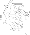
- the sheet can be folded along the two pressed lines 121 along a direction toward the main body portion 11 to an extent that the inner surface of the first left-side fixing region 122 faces the inner surface of the third left-side fixing region 124 (see FIG. 2 ).
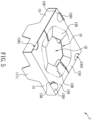
- the first connecting portion 14 can be bent along a direction toward the main body portion 11 (see FIG. 3 ).
- the third left-side fixing region 124 can be bent along its joint with the first connecting portion 14 to the extent that the outer surface of the first left-side fixing region 122 faces the inner surface of the main body portion 11 (see FIG.
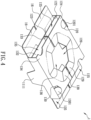
- the folded third left-side fixing region 124 is formed and positioned above the main body portion 11, the outer surface of the third left-side fixing region 124 forms an exposed part of the packaging structure 1, and the front ends of the folded first left-side fixing region 122, second left-side fixing region 123, third left-side fixing region 124 and the first connecting portion 14 forming a first left assembly opening 125, and the rear ends of the folded first left-side fixing region 122, second left-side fixing region 123, third left-side fixing region 124 and the first connecting portion 14 forming a second left assembly opening 125 (see FIG. 4 ).
- the right fixing portion 13 is provided thereon with two pressed lines 131, and the two pressed lines 131 are spaced apart from each other such that the right fixing portion 13 is divided by the two pressed lines 131 into a first right-side fixing region 132, a second right-side fixing region 133, and a third right-side fixing region 134.
- the two pressed lines 131 are located on two opposite sides of the second right-side fixing region 133, respectively.
- the first right-side fixing region 132 is located to the right of the second right-side fixing region 133
- the third right-side fixing region 134 is located to the left of the second right-side fixing region 133.
- the sheet can be folded along the two pressed lines 131 along a direction toward the main body portion 11 to an extent that the inner surface of the first right-side fixing region 132 faces the inner surface of the third right-side fixing region 134 (see FIG. 2 ).
- the second connecting portion 14 can be bent along a direction toward the main body portion 11 (see FIG. 3 ).
- the third right-side fixing region 134 can be bent along its joint with the second connecting portion 14 to the extent that the outer surface of the first right-side fixing region 132 faces the inner surface of the main body portion 11 (see FIG.
- the folded third right-side fixing region 134 is formed and positioned above the main body portion 11, the outer surface of the third right-side fixing region 134 forms an exposed part of the packaging structure 1, the front ends of the folded first right-side fixing region 132, second right-side fixing region 133, third right-side fixing region 134 and the second connecting portion 14 form a first right assembly opening 135, and the rear ends of the folded first right-side fixing region 132, second right-side fixing region 133, third right-side fixing region 134 and the second connecting portion 14 form a second right assembly opening 135 (see FIG. 4 ).
- the sheet can be folded into the shape shown in FIG. 4 .
- the left fixing portion 12 can be folded and positioned on the left part of the top side of the main body portion 11, and the right fixing portion 13 can be folded and positioned on the right part of the top side of the main body portion 11, such that the left and right assembly openings 125 and 135 at the same side are spaced apart from each other by a distance, for example, by at least the sheet thickness of the second left-side fixing region 123 and the sheet thickness of the second right-side fixing region 133).
- the area between the two pressed lines 121 of the folded left fixing portion 12 i.e., the second left-side fixing region 123 is adjacent to or abuts against the area between the two pressed lines 131 of the folded right fixing portion 13 (i.e., the second right-side fixing region 133), so if the left fixing portion 12 and the right fixing portion 13 start to unfold outward (i.e., move away from the main body portion 11) due to their own restoring forces, the second left-side fixing region 123 and the second right-side fixing region 133 will be blocked by each other and keep the left fixing portion 12 and the right fixing portion 13 where they are, preventing the two fixing portions 12 and 13 from parting, and thereby providing higher stability to the packaging structure 1.
- the inserting flaps 16 can be respectively inserted into the left assembly openings 125 and the right assembly openings 135, so as to cover the corresponding left assembly openings 125 and the right assembly openings 135.
- the main body portion 11 is provided with a plurality of U-shaped cutting lines 111 to form a plurality of supporting members 1111.
- Each U-shaped cutting line 111 has two ends, and each end is arranged at the joint between the main body portion 11 and a connecting portion 14 corresponding and connected to the U-shaped cutting line 111 or the joint between the main body portion 11 and a folding portion 15 corresponding and connected to the U-shaped cutting line 111, that is, arranged at at least one of the four edges of the main body portion 11.
- the free end of each supporting member 1111 is folded to point away from the bottom side of the packaging structure 1.
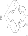
- each of the supporting members 1111 can abut against the inner wall of the packaging box to form at least one bottom space 18 (see FIG. 6 ) between the main body portion 11 and the inner wall of the packaging box as a storage space for the accessories (e.g., the transformer) of the packaged product 2.
- the locations and number of the U-shaped cutting lines 111 can be adjusted according to product requirements.
- the U-shaped cutting lines 111 may be so arranged that their ends are located only at the joints between the main body portion 11 and the two connecting portions 14 or only at the joints between the main body portion 11 and the two folding portions 15.
- At least one U-shaped cutting line 111 is provided at or adjacent to a central area of the main body portion 11 (see FIG. 7 ), and a pressed line 112 is provided between the two ends of this U-shaped cutting line 111 so that the supporting member 1111 defined by the U-shaped cutting line 111 can be bent along the pressed line 112 away from the bottom side of the folded packaging structure 1 to an intended position.
- the left fixing portion 12 can be provided with a left opening 126 that extends from the first left-side fixing region 122 across the second left-side fixing region 123 to the third left-side fixing region 124.
- a portion of the periphery of the third left-side fixing region 124 that defines, collectively with the first left-side fixing region 122 and the second left-side fixing region 123, the left opening 126 is provided with a plurality of left cuttings 127 that extend along a direction away from the left opening 126 to form a plurality of left resilient positioning flaps 129.
- the left resilient positioning flaps 129 can be bent away from the left opening 126.
- the right fixing portion 13 can be provided with a right opening 136 that extends from the first right-side fixing region 132 across the second right-side fixing region 133 to the third right-side fixing region 134.
- a portion of the periphery of the third right-side fixing region 134 that defines, collectively with the first right-side fixing region 132 and the second right-side fixing region 133, the right opening 136 is provided with a plurality of right cuttings 137 that extend along a direction away from the right opening 136 to form a plurality of right resilient positioning flaps 139.
- the right resilient positioning flaps 139 can be bent away from the right opening 136. In a folded state of the packaging structure 1, a portion of the left opening 126 is in communication with a portion of the right opening 136.
- a receiving space 19 can be formed and defined by the main body portion 11, left fixing portion 12 and right fixing portion 13 of the packaging structure 1 in a folded state.
- the left resilient positioning flaps 129 and the right resilient positioning flaps 139 extend to, that is, are positioned at, the top side of the receiving space 19, with a positioning opening 10 formed and surrounded by the edges of the free ends of the left and right resilient positioning flaps 129 and 139.
- the positioning opening 10 may be polygonal. However, the present disclosure is not limited thereto.
- the positioning opening 10 is in communication with the receiving space 19.
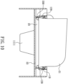
- the left resilient positioning flaps 129 and the right resilient positioning flaps 139 can be engaged in a concave space 230 of a product 2 that is defined by a neck of the product 2 when the product 2 extends into the receiving space 19 through the positioning opening 10.
- the neck 23 of the product 2 can be formed between a main body 21 and a base 22 of the product 2 due to the outer diameter difference between the main body 21 and the base 22, and the concave space 230 is defined by the peripheral of the neck 23.
- the neck 23 and the concave space 230 can be formed at a portion of the base 22 that is adjacent to the top side of the base 22 when the width of the top side of the base 22 is smaller than the width of the bottom side of the main body 21 and the width of the bottom side of the base 22 is larger than the width of the top side of the base 22, that is, a space sunken toward the central axis of the product 2 is formed in the portion of the base 22 that is adjacent to the top side of the base 22.
- the neck 23 is not necessarily formed at the base 22, and may be formed at the main body 21.
- the product 2 may have an integrally formed housing and does not have the main body 21 and the base 22 as two separate elements. As long as a product has a neck forming a concave space in which the left resilient positioning flaps 129 and the right resilient positioning flaps 139 can be engaged, such a product falls within the scope of the product 2 defined by the present disclosure, and a portion of such a product that lies below the left resilient positioning flaps 129 and the right resilient positioning flaps 139 when the product is positioned in the packaging structure 1 falls within the scope of the base 22 as defined by the present disclosure.
- the base 22 pushes, bends and deforms the left resilient positioning flaps 129 and the right resilient positioning flaps 139 toward the bottom side of the packaging structure 1 (see FIG. 9 ).
- the left resilient positioning flaps 129 and the right resilient positioning flaps 139 move upward by their own restoring forces, which tend to restore the positioning flaps to their respective pre-deformed positions.
- the packaging structure 1 can protect the product 2 with small cushioning space, and can effectively prevent the product 2 from falling (i.e., from separating from the packaging structure 1) and provide shock absorption while the product 2 is being transported.
- the third left-side fixing region 124 is provided with a cutting 120
- the third right-side fixing region 134 is provided with a cutting 130, so as to facilitate removal of the packaging structure 1 from inside a packaging box.
- the cuttings 120 and 130 can be semicircular and be respectively provided at the joint between the left fixing portion 12 and the first connecting portion 14 and the joint between the right fixing portion 13 and the second connecting portion 14 to form pulling portions 1201 and 1301 respectively.
- Each pulling portion 1201 or 1301 can be bent away from the receiving space 19 to its intended position so that a user can take the packaging structure 1 out of a packaging box by applying a pulling force to the two pulling portions 1201 and 1301.
- the present application is not limited thereto.
- the shape of the cuttings 120 and 130 can be adjusted according to product requirements (e.g., into a rectangular shape), as long as the pulling portions 1201 and 1301 can be formed by bending the packaging structure 1, and a user can easily remove the packaging structure 1 from inside a packaging box with the aid of the pulling portions 1201 and 1301.
- the third left-side fixing region 124 is provided with at least one aperture 1241
- the third right-side fixing region 134 is provided with at least one aperture 1341, so as to facilitate a user to unfold a folded packaging structure 1.
- the at least one aperture 1241 can be formed at at least one end of the third left-side fixing region 124
- the at least one aperture 1341 can be formed at at least one end of the third right-side fixing region 134 that is opposite to the at least one end of the third left-side fixing regions 124 at which the at least one aperture 1241 is formed.
- the aperture 1241 and the aperture 1341 can be formed at two opposite ends of the packaging structure 1, such as the aperture 1241 being formed at the front end of the third left-side fixing region 124 and the aperture 1341 being formed at the rear end of the third right-side fixing region 134, or the aperture 1241 being formed at the rear end of the third left-side fixing region 124 and the aperture 1341 being formed at the front end of the third right-side fixing region 134.
- the apertures 1241 and 1341 can partially expose the inserting flaps 16 corresponding to the apertures 1241 and 1341 when the packaging structure 1 is folded, so that a user can easily move those inserting flaps 16 out of the corresponding left assembly opening(s) 125 and the corresponding right assembly opening(s) 135 respectively by the two apertures 1241 and 1341, so as to release the packaging structure 1 from a fixedly folded state.
- the present disclosure provides an integrally formed sheet whose left fixing portion 12 and right fixing portion 13 can be folded along a direction toward the main body portion 11 to be adjacent to or abut against each other, and whose inserting flaps 16 can be subsequently inserted into the left assembly openings 125 and the right assembly openings 135 respectively to present a folding of the packaging structure 1.
- the packaging structure 1 can be rendered into its particular shape simply by folding the sheet, without using any adhesive or binding material, a worker or user can fold the packaging structure 1 into shape with ease, and the overall packaging cost is effectively lowered.
- the packaging structure 1 can be easily unfolded and removed from the packaged product to facilitate recycling and reuse of the packaging structure 1.
Landscapes
- Engineering & Computer Science (AREA)
- Mechanical Engineering (AREA)
- Cartons (AREA)
- Buffer Packaging (AREA)
Claims (10)
- Verpackungsstruktur, darin eingeschlossen eine faltbare, integral geformte Platte, wobei die integral geformte Platte Folgendes umfasst:einen Hauptkörperabschnitt (11),einen ersten Verbindungsabschnitt (14) mit einer ersten Kante, die mit einer linken Kante des Hauptkörperabschnitts (11) verbunden und konfiguriert ist, um entlang einer Richtung hin zum Hauptkörperabschnitt (11) gebogen zu sein;einen zweiten Verbindungsabschnitt (14) mit einer ersten Kante, die mit einer rechten Kante des Hauptkörperabschnitts (11) verbunden und konfiguriert ist, um entlang einer Richtung hin zum Hauptkörperabschnitt (11) gebogen zu sein;einen ersten Faltabschnitt (15), der sich nach außen von einer vorderen Kante des Hauptkörperabschnitts (11) erstreckt und konfiguriert ist, um entlang einer Richtung hin zum Hauptköperabschnitt (11) gebogen zu sein;einen zweiten Faltabschnitt (15), der sich nach außen von einer hinteren Kante des Hauptkörperabschnitts (11) erstreckt und konfiguriert ist, um entlang einer Richtung hin zum Hauptköperabschnitt (11) gebogen zu sein;zwei erste Einführungsklappen (16), die sich nach außen vom ersten Faltabschnitt (15) erstrecken und voneinander beabstandet sind;zwei zweite Einführungsklappen (16), die sich nach außen vom zweiten Faltabschnitt (15) erstrecken und voneinander beabstandet sind;einen linken Befestigungsabschnitt (12), der mit einer zweiten Kante des ersten Verbindungsabschnitts (14) verbunden ist, der darauf mit zwei ersten eingestanzten Linien (121), die voneinander beabstandet sind, und einer linken Öffnung (126) gebildet ist, und konfiguriert, um entlang der zwei ersten eingestanzten Linien (121) entlang einer Richtung hin zum Hauptkörperabschnitt (11) gebogen zu sein, wobei ein Abschnitt eines Umfangs der linken Öffnung (126) mit einer Vielzahl von linken Schnitten (127) gebildet ist, die sich entlang einer Richtung weg von der linken Öffnung (126) erstrecken, um eine Vielzahl von linken elastischen Positionierungsklappen (129) zu bilden, die konfiguriert ist, um weg von der linken Öffnung (126) gebogen zu sein; undeinen rechten Befestigungsabschnitt (13), der mit einer zweiten Kante des zweiten Verbindungsabschnitts (14) verbunden ist, der darauf mit zwei zweiten eingestanzten Linien (131), die voneinander beabstandet sind, und einer rechten Öffnung (136) gebildet ist, und konfiguriert, um entlang der zwei zweiten eingestanzten Linien (131) entlang einer Richtung hin zum Hauptkörperabschnitt (11) gebogen zu sein, wobei ein Abschnitt eines Umfangs der rechten Öffnung (136) mit einer Vielzahl von rechten Schnitten (137) gebildet ist, die sich entlang einer Richtung weg von der rechten Öffnung (136) erstrecken, um eine Vielzahl von rechten elastischen Positionierungsklappen (139) zu bilden, die konfiguriert ist, um weg von der rechten Öffnung (136) gebogen zu sein,wobei die faltbare, integral geformte Platte konfiguriert ist, um gefaltet zu werden, um den linken Befestigungsabschnitt (12) auf einen linken Teil einer oberen Seite des Hauptkörperabschnitts (11) zu positionieren, den rechten Befestigungsabschnitt (13) auf einen rechten Teil einer oberen Seite des Hauptkörperabschnitts (11) zu positionieren, einen ersten Bereich des gefalteten linken Befestigungsabschnitts (12), der sich zwischen den ersten eingestanzten Linien (121) befindet, zu positionieren, um nahe an einem zweiten Bereich der gefalteten rechten Befestigungsabschnitts (13) zu sein oder gegen diesen anzustoßen, der sich zwischen den zweiten eingestanzten Linien (131) befindet, die linke Öffnung (126) mit der rechten Öffnung (136) in Verbindung zu bringen, einen Aufnahmeraum (19) zu bilden, der durch den Hauptkörperabschnitt (11), den linken Befestigungsabschnitt (12) und den rechten Befestigungsabschnitt (13) definiert ist, die rechten flexiblen Positionierungsklappen (139) und die linken flexiblen Positionierungsklappen (129) auf einer oberen Seite des Aufnahmeraums (19) zu positionieren und eine Positionierungsöffnung (10) bilden, die mit dem Aufnahmeraum (19) durch Kanten von freien Enden der rechten flexiblen Positionierungsklappen (139) und der linken flexiblen Positionierungsklappen (129) in Verbindung steht.
- Verpackungsstruktur nach Anspruch 1, wobei die rechten flexiblen Positionierungsklappen (139) und die linken flexiblen Positionierungsklappen (129) konfiguriert sind, um, wenn ein Produkt (2) eingeführt wird oder sich von der Positionierungsöffnung (10) in den Aufnahmeraum erstreckt, hin zu einer unteren Seite der Verpackungsstruktur (1) durch eine Basis (22) des Produkts (2) geschoben und gebogen zu werden, und, nachdem sich die Basis (22) an den freien Enden der linken flexiblen Positionierungsklappen (129) und den rechten flexiblen Positionierungsklappen (139) vorbei bewegt hat, sich nach oben zu bewegen, um in einen konkaven Raum (230) des Produkts (2) einzugreifen, um das Produkt (2) in der Verpackungsstruktur (1) zu positionieren.
- Verpackungsstruktur nach Anspruch 1, wobei die Positionierungsöffnung (10) polygonal ist.
- Verpackungsstruktur nach Anspruch 1, wobei der linke Befestigungsabschnitt (12) konfiguriert ist, um, wenn er gefaltet ist, um auf der oberen Seite des Hauptkörperabschnitts (11) positioniert zu sein, linke Montageöffnungen (125) mit einem vorderen Ende und einem hinteren Ende des ersten Verbindungsabschnitts (14) zu bilden, und der rechte Befestigungsabschnitt (13) konfiguriert ist, um, wenn er gefaltet ist, um auf der oberen Seite des Hauptkörperabschnitts (11) positioniert zu sein, rechte Montageöffnungen (135) mit einem vorderen Ende und einem hinteren Ende des zweiten Verbindungsabschnitts (14) zu bilden.
- Verpackungsstruktur nach Anspruch 1, wobei der Hauptkörperabschnitt (11) mit einer Vielzahl von U-förmigen Schnittlinien (111) ausgestattet ist, um eine Vielzahl von Tragelementen (1111) zu bilden, wobei jedes Tragelement (1111) ein freies Ende aufweist, das konfiguriert ist, um gefaltet zu werden, um weg von einer unteren Seite der Verpackungsstruktur (1) zu zeigen.
- Verpackungsstruktur nach Anspruch 5, wobei sich zwei Enden jeder der U-förmigen Schnittlinien (111) an einer Verbindung zwischen dem Hauptkörperabschnitt (11) und einem des ersten und zweiten Verbindungsabschnitts (14) oder einer Verbindung zwischen dem Hauptkörperabschnitt (11) und einem des ersten und zweiten Faltabschnitts (15) befinden.
- Verpackungsstruktur nach Anspruch 5, wobei mindestens eine der U-förmigen Schnittlinien (111) an oder benachbart einem zentralen Bereich des Hauptkörperabschnitts (11) bereitgestellt ist, eine eingestanzte Linie (112) zwischen den zwei Enden der U-förmigen Schnittlinie (111) bereitgestellt ist, und ein Tragelement (1111), definiert von der U-förmigen Schnittlinie (111), konfiguriert ist, um entlang der eingestanzten Linie (112) weg von der unteren Seite der Verpackungsstruktur (1) gebogen zu sein.
- Verpackungsstruktur nach einem der Ansprüche 5 - 7, wobei eine untere Kante jedes der Tragelemente (1111) konfiguriert ist, um, wenn die Verpackungsstruktur (1) gefaltet und in eine Verpackungsbox platziert ist, gegen eine innere Wand der Verpackungsbox anstoßen, um mindestens einen unteren Raum (18) zwischen dem Hauptkörperabschnitt (11) und der inneren Wand der Verpackungsbox zu bilden.
- Verpackungsstruktur nach Anspruch 1, wobei jeder des linken Befestigungsabschnitts (12) und des rechten Befestigungsabschnitts (13) mit einem Schnitt (120, 130) ausgestattet ist, um einen Zugabschnitt (1201, 1301) zu bilden, der konfiguriert ist, um weg vom Aufnahmeabschnitt (19) gebogen zu sein.
- Verpackungsstruktur nach Anspruch 1, wobei mindestens ein erster Durchlass (1241) an mindestens einem eines vorderen Endes und eines hinteren Endes des linken Befestigungsabschnitts (12) gebildet ist, mindestens ein zweiter Durchlass (1341) an mindestens einem eines vorderen Endes und eines hinteren Endes des rechten Befestigungsabschnitts (13) gebildet ist, und sich der erste und zweite Durchlass (1241, 1341) jeweils an zwei gegenüberliegenden Enden der Verpackungsstruktur (1) befinden und konfiguriert sind, um teilweise mindestens zwei der ersten und zweiten Einführungsklappen (16) freizugeben, die den Durchlässen (1241, 1341) entsprechen, wenn die faltbare integral gebildete Platte gefaltet ist, um den linken Befestigungsabschnitt (12) und den rechten Befestigungsabschnitt (13) auf die obere Seite des Hauptkörperabschnitts (11) zu positionieren, und die zwei Einführungsklappen (16) in die Montageöffnungen (125, 135) eingeführt sind, die den zwei Einführungsklappen (16) entsprechen, die jeweils durch einen des linken und rechten Befestigungsabschnitts (12, 13) und einen des ersten und zweiten Verbindungsabschnitts (14) gebildet sind.
Applications Claiming Priority (1)
| Application Number | Priority Date | Filing Date | Title |
|---|---|---|---|
| TW109140880A TWI748760B (zh) | 2020-11-20 | 2020-11-20 | 具定位彈片之包裝結構 |
Publications (2)
| Publication Number | Publication Date |
|---|---|
| EP4001146A1 EP4001146A1 (de) | 2022-05-25 |
| EP4001146B1 true EP4001146B1 (de) | 2023-02-22 |
Family
ID=75562531
Family Applications (1)
| Application Number | Title | Priority Date | Filing Date |
|---|---|---|---|
| EP21168547.4A Active EP4001146B1 (de) | 2020-11-20 | 2021-04-15 | Verpackungsstruktur mit elastischen positionierungsklappen |
Country Status (3)
| Country | Link |
|---|---|
| US (1) | US11407553B2 (de) |
| EP (1) | EP4001146B1 (de) |
| TW (1) | TWI748760B (de) |
Families Citing this family (3)
| Publication number | Priority date | Publication date | Assignee | Title |
|---|---|---|---|---|
| CN114537834B (zh) * | 2020-11-25 | 2024-03-29 | 明泰科技股份有限公司 | 具有定位弹片的包装结构 |
| IT202300002085A1 (it) * | 2023-02-08 | 2024-08-08 | Alessandro Zanetti | Vassoio per confezionamento |
| US20250304349A1 (en) * | 2024-03-29 | 2025-10-02 | Sonos, Inc. | Packaging system |
Family Cites Families (15)
| Publication number | Priority date | Publication date | Assignee | Title |
|---|---|---|---|---|
| US1604301A (en) * | 1924-12-01 | 1926-10-26 | Radions Ltd | Package for fragile articles |
| US4019672A (en) * | 1976-02-03 | 1977-04-26 | Packaging Corporation Of America | Packing insert and blank therefor |
| US4244128A (en) * | 1979-02-12 | 1981-01-13 | Alton Box Board Company | Paperboard picture display |
| US5385238A (en) * | 1992-07-01 | 1995-01-31 | The Mead Corporation | Cushion for use in a shipping container |
| US5341931A (en) * | 1993-06-22 | 1994-08-30 | Prochaska Gerhard W | Package liner for rectangular object |
| US5884767A (en) * | 1997-12-04 | 1999-03-23 | Chicony Electronics Co., Ltd | Keypad packing box |
| US8240466B2 (en) * | 2007-08-22 | 2012-08-14 | Meador Iii William Edward | Paperboard media package |
| JP5683583B2 (ja) * | 2009-07-10 | 2015-03-11 | グラフィック パッケージング インターナショナル インコーポレイテッド | 容器用パッケージ |
| DE102011011673B4 (de) * | 2011-02-15 | 2016-07-07 | Vesta Heyn | Zuschnitt aus einem biegsamen, flächigen Material zur Herstellung eines Bilderrahmens sowie ein Bilderrahmen gefertigt aus dem Zuschnitt |
| TWM426573U (en) * | 2011-07-01 | 2012-04-11 | Kinpo Elect Inc | Packing box structure |
| GB2508000A (en) * | 2012-11-16 | 2014-05-21 | P4Ck Ltd | Drinks Carrier |
| CN105217120A (zh) * | 2015-09-11 | 2016-01-06 | 上海华会信息科技有限公司 | 环保型盆栽包装 |
| US9731861B2 (en) * | 2016-01-11 | 2017-08-15 | Westrock Shared Services, Llc | Base assembly with reinforcing support panels and blanks for forming the same |
| FR3082510B1 (fr) * | 2018-06-19 | 2021-04-30 | Very Bloom | Emballage pour produit horticole |
| CN211520224U (zh) * | 2019-12-11 | 2020-09-18 | 大连乐焙进出口有限公司 | 一种手提式包装盒 |
-
2020
- 2020-11-20 TW TW109140880A patent/TWI748760B/zh active
-
2021
- 2021-04-11 US US17/227,319 patent/US11407553B2/en active Active
- 2021-04-15 EP EP21168547.4A patent/EP4001146B1/de active Active
Also Published As
| Publication number | Publication date |
|---|---|
| EP4001146A1 (de) | 2022-05-25 |
| US11407553B2 (en) | 2022-08-09 |
| TW202220906A (zh) | 2022-06-01 |
| TWI748760B (zh) | 2021-12-01 |
| US20220161961A1 (en) | 2022-05-26 |
Similar Documents
| Publication | Publication Date | Title |
|---|---|---|
| US11407553B2 (en) | Packaging structure with resilient positioning flaps | |
| US5522539A (en) | Tote box with block insert locking capability | |
| US7726489B2 (en) | Packaging box | |
| CN109641676B (zh) | 具有保持装置的展示盒 | |
| US4019672A (en) | Packing insert and blank therefor | |
| US20140138429A1 (en) | Retail Sealed Folding Box With Handle | |
| US8181788B2 (en) | Recloseable, folding container and blanks and method of manufacturing | |
| RU2323863C2 (ru) | Усовершенствования, касающиеся подставок из гофрированного картона | |
| US6357652B1 (en) | Extension box and shipping carton system | |
| KR101289408B1 (ko) | 접이식 포장 상자 | |
| JP6549391B2 (ja) | 収納箱 | |
| CA2613633C (en) | Apparatus and method for handles integrated with product containers | |
| JP5619489B2 (ja) | 緩衝機能付包装用箱 | |
| JP3229897U (ja) | 保持材 | |
| US7614501B2 (en) | Utility and protective packaging system | |
| KR102259858B1 (ko) | 하중강화형 조립식 포장상자 및 그 조립방법 | |
| KR20130100644A (ko) | 자동화 공정이 가능한 포장 상자 | |
| JP2020189685A (ja) | 商品包装箱 | |
| US20180370677A1 (en) | Tear-away package and shipping tray converted therefrom | |
| JP7784225B2 (ja) | 包装箱 | |
| KR101394632B1 (ko) | 자동화 공정이 가능한 포장 상자 | |
| JP7542850B2 (ja) | 緩衝具付き箱体 | |
| JP3591898B2 (ja) | 包装装置 | |
| JP5374988B2 (ja) | ユニット梱包箱 | |
| CN210028293U (zh) | 包装盒 |
Legal Events
| Date | Code | Title | Description |
|---|---|---|---|
| PUAI | Public reference made under article 153(3) epc to a published international application that has entered the european phase |
Free format text: ORIGINAL CODE: 0009012 |
|
| STAA | Information on the status of an ep patent application or granted ep patent |
Free format text: STATUS: REQUEST FOR EXAMINATION WAS MADE |
|
| 17P | Request for examination filed |
Effective date: 20210421 |
|
| AK | Designated contracting states |
Kind code of ref document: A1 Designated state(s): AL AT BE BG CH CY CZ DE DK EE ES FI FR GB GR HR HU IE IS IT LI LT LU LV MC MK MT NL NO PL PT RO RS SE SI SK SM TR |
|
| RBV | Designated contracting states (corrected) |
Designated state(s): AL AT BE BG CH CY CZ DE DK EE ES FI FR GB GR HR HU IE IS IT LI LT LU LV MC MK MT NL NO PL PT RO RS SE SI SK SM TR |
|
| GRAP | Despatch of communication of intention to grant a patent |
Free format text: ORIGINAL CODE: EPIDOSNIGR1 |
|
| STAA | Information on the status of an ep patent application or granted ep patent |
Free format text: STATUS: GRANT OF PATENT IS INTENDED |
|
| INTG | Intention to grant announced |
Effective date: 20221007 |
|
| GRAS | Grant fee paid |
Free format text: ORIGINAL CODE: EPIDOSNIGR3 |
|
| GRAA | (expected) grant |
Free format text: ORIGINAL CODE: 0009210 |
|
| STAA | Information on the status of an ep patent application or granted ep patent |
Free format text: STATUS: THE PATENT HAS BEEN GRANTED |
|
| AK | Designated contracting states |
Kind code of ref document: B1 Designated state(s): AL AT BE BG CH CY CZ DE DK EE ES FI FR GB GR HR HU IE IS IT LI LT LU LV MC MK MT NL NO PL PT RO RS SE SI SK SM TR |
|
| REG | Reference to a national code |
Ref country code: GB Ref legal event code: FG4D |
|
| REG | Reference to a national code |
Ref country code: CH Ref legal event code: EP |
|
| REG | Reference to a national code |
Ref country code: AT Ref legal event code: REF Ref document number: 1549365 Country of ref document: AT Kind code of ref document: T Effective date: 20230315 Ref country code: IE Ref legal event code: FG4D |
|
| REG | Reference to a national code |
Ref country code: DE Ref legal event code: R096 Ref document number: 602021001434 Country of ref document: DE |
|
| REG | Reference to a national code |
Ref country code: LT Ref legal event code: MG9D |
|
| REG | Reference to a national code |
Ref country code: NL Ref legal event code: MP Effective date: 20230222 |
|
| REG | Reference to a national code |
Ref country code: AT Ref legal event code: MK05 Ref document number: 1549365 Country of ref document: AT Kind code of ref document: T Effective date: 20230222 |
|
| PG25 | Lapsed in a contracting state [announced via postgrant information from national office to epo] |
Ref country code: RS Free format text: LAPSE BECAUSE OF FAILURE TO SUBMIT A TRANSLATION OF THE DESCRIPTION OR TO PAY THE FEE WITHIN THE PRESCRIBED TIME-LIMIT Effective date: 20230222 Ref country code: PT Free format text: LAPSE BECAUSE OF FAILURE TO SUBMIT A TRANSLATION OF THE DESCRIPTION OR TO PAY THE FEE WITHIN THE PRESCRIBED TIME-LIMIT Effective date: 20230622 Ref country code: NO Free format text: LAPSE BECAUSE OF FAILURE TO SUBMIT A TRANSLATION OF THE DESCRIPTION OR TO PAY THE FEE WITHIN THE PRESCRIBED TIME-LIMIT Effective date: 20230522 Ref country code: NL Free format text: LAPSE BECAUSE OF FAILURE TO SUBMIT A TRANSLATION OF THE DESCRIPTION OR TO PAY THE FEE WITHIN THE PRESCRIBED TIME-LIMIT Effective date: 20230222 Ref country code: LV Free format text: LAPSE BECAUSE OF FAILURE TO SUBMIT A TRANSLATION OF THE DESCRIPTION OR TO PAY THE FEE WITHIN THE PRESCRIBED TIME-LIMIT Effective date: 20230222 Ref country code: LT Free format text: LAPSE BECAUSE OF FAILURE TO SUBMIT A TRANSLATION OF THE DESCRIPTION OR TO PAY THE FEE WITHIN THE PRESCRIBED TIME-LIMIT Effective date: 20230222 Ref country code: HR Free format text: LAPSE BECAUSE OF FAILURE TO SUBMIT A TRANSLATION OF THE DESCRIPTION OR TO PAY THE FEE WITHIN THE PRESCRIBED TIME-LIMIT Effective date: 20230222 Ref country code: ES Free format text: LAPSE BECAUSE OF FAILURE TO SUBMIT A TRANSLATION OF THE DESCRIPTION OR TO PAY THE FEE WITHIN THE PRESCRIBED TIME-LIMIT Effective date: 20230222 Ref country code: AT Free format text: LAPSE BECAUSE OF FAILURE TO SUBMIT A TRANSLATION OF THE DESCRIPTION OR TO PAY THE FEE WITHIN THE PRESCRIBED TIME-LIMIT Effective date: 20230222 |
|
| PG25 | Lapsed in a contracting state [announced via postgrant information from national office to epo] |
Ref country code: SE Free format text: LAPSE BECAUSE OF FAILURE TO SUBMIT A TRANSLATION OF THE DESCRIPTION OR TO PAY THE FEE WITHIN THE PRESCRIBED TIME-LIMIT Effective date: 20230222 Ref country code: PL Free format text: LAPSE BECAUSE OF FAILURE TO SUBMIT A TRANSLATION OF THE DESCRIPTION OR TO PAY THE FEE WITHIN THE PRESCRIBED TIME-LIMIT Effective date: 20230222 Ref country code: IS Free format text: LAPSE BECAUSE OF FAILURE TO SUBMIT A TRANSLATION OF THE DESCRIPTION OR TO PAY THE FEE WITHIN THE PRESCRIBED TIME-LIMIT Effective date: 20230622 Ref country code: GR Free format text: LAPSE BECAUSE OF FAILURE TO SUBMIT A TRANSLATION OF THE DESCRIPTION OR TO PAY THE FEE WITHIN THE PRESCRIBED TIME-LIMIT Effective date: 20230523 Ref country code: FI Free format text: LAPSE BECAUSE OF FAILURE TO SUBMIT A TRANSLATION OF THE DESCRIPTION OR TO PAY THE FEE WITHIN THE PRESCRIBED TIME-LIMIT Effective date: 20230222 |
|
| PG25 | Lapsed in a contracting state [announced via postgrant information from national office to epo] |
Ref country code: SM Free format text: LAPSE BECAUSE OF FAILURE TO SUBMIT A TRANSLATION OF THE DESCRIPTION OR TO PAY THE FEE WITHIN THE PRESCRIBED TIME-LIMIT Effective date: 20230222 Ref country code: RO Free format text: LAPSE BECAUSE OF FAILURE TO SUBMIT A TRANSLATION OF THE DESCRIPTION OR TO PAY THE FEE WITHIN THE PRESCRIBED TIME-LIMIT Effective date: 20230222 Ref country code: EE Free format text: LAPSE BECAUSE OF FAILURE TO SUBMIT A TRANSLATION OF THE DESCRIPTION OR TO PAY THE FEE WITHIN THE PRESCRIBED TIME-LIMIT Effective date: 20230222 Ref country code: DK Free format text: LAPSE BECAUSE OF FAILURE TO SUBMIT A TRANSLATION OF THE DESCRIPTION OR TO PAY THE FEE WITHIN THE PRESCRIBED TIME-LIMIT Effective date: 20230222 Ref country code: CZ Free format text: LAPSE BECAUSE OF FAILURE TO SUBMIT A TRANSLATION OF THE DESCRIPTION OR TO PAY THE FEE WITHIN THE PRESCRIBED TIME-LIMIT Effective date: 20230222 |
|
| REG | Reference to a national code |
Ref country code: DE Ref legal event code: R097 Ref document number: 602021001434 Country of ref document: DE |
|
| PG25 | Lapsed in a contracting state [announced via postgrant information from national office to epo] |
Ref country code: SK Free format text: LAPSE BECAUSE OF FAILURE TO SUBMIT A TRANSLATION OF THE DESCRIPTION OR TO PAY THE FEE WITHIN THE PRESCRIBED TIME-LIMIT Effective date: 20230222 |
|
| PG25 | Lapsed in a contracting state [announced via postgrant information from national office to epo] |
Ref country code: LU Free format text: LAPSE BECAUSE OF NON-PAYMENT OF DUE FEES Effective date: 20230415 |
|
| PLBE | No opposition filed within time limit |
Free format text: ORIGINAL CODE: 0009261 |
|
| STAA | Information on the status of an ep patent application or granted ep patent |
Free format text: STATUS: NO OPPOSITION FILED WITHIN TIME LIMIT |
|
| REG | Reference to a national code |
Ref country code: BE Ref legal event code: MM Effective date: 20230430 |
|
| PG25 | Lapsed in a contracting state [announced via postgrant information from national office to epo] |
Ref country code: MC Free format text: LAPSE BECAUSE OF FAILURE TO SUBMIT A TRANSLATION OF THE DESCRIPTION OR TO PAY THE FEE WITHIN THE PRESCRIBED TIME-LIMIT Effective date: 20230222 |
|
| 26N | No opposition filed |
Effective date: 20231123 |
|
| PG25 | Lapsed in a contracting state [announced via postgrant information from national office to epo] |
Ref country code: SI Free format text: LAPSE BECAUSE OF FAILURE TO SUBMIT A TRANSLATION OF THE DESCRIPTION OR TO PAY THE FEE WITHIN THE PRESCRIBED TIME-LIMIT Effective date: 20230222 Ref country code: MC Free format text: LAPSE BECAUSE OF FAILURE TO SUBMIT A TRANSLATION OF THE DESCRIPTION OR TO PAY THE FEE WITHIN THE PRESCRIBED TIME-LIMIT Effective date: 20230222 |
|
| REG | Reference to a national code |
Ref country code: IE Ref legal event code: MM4A |
|
| PG25 | Lapsed in a contracting state [announced via postgrant information from national office to epo] |
Ref country code: BE Free format text: LAPSE BECAUSE OF NON-PAYMENT OF DUE FEES Effective date: 20230430 |
|
| PG25 | Lapsed in a contracting state [announced via postgrant information from national office to epo] |
Ref country code: IE Free format text: LAPSE BECAUSE OF NON-PAYMENT OF DUE FEES Effective date: 20230415 |
|
| PG25 | Lapsed in a contracting state [announced via postgrant information from national office to epo] |
Ref country code: IE Free format text: LAPSE BECAUSE OF NON-PAYMENT OF DUE FEES Effective date: 20230415 |
|
| PG25 | Lapsed in a contracting state [announced via postgrant information from national office to epo] |
Ref country code: IT Free format text: LAPSE BECAUSE OF FAILURE TO SUBMIT A TRANSLATION OF THE DESCRIPTION OR TO PAY THE FEE WITHIN THE PRESCRIBED TIME-LIMIT Effective date: 20230222 |
|
| PG25 | Lapsed in a contracting state [announced via postgrant information from national office to epo] |
Ref country code: BG Free format text: LAPSE BECAUSE OF FAILURE TO SUBMIT A TRANSLATION OF THE DESCRIPTION OR TO PAY THE FEE WITHIN THE PRESCRIBED TIME-LIMIT Effective date: 20230222 |
|
| PG25 | Lapsed in a contracting state [announced via postgrant information from national office to epo] |
Ref country code: BG Free format text: LAPSE BECAUSE OF FAILURE TO SUBMIT A TRANSLATION OF THE DESCRIPTION OR TO PAY THE FEE WITHIN THE PRESCRIBED TIME-LIMIT Effective date: 20230222 |
|
| REG | Reference to a national code |
Ref country code: CH Ref legal event code: PL |
|
| PG25 | Lapsed in a contracting state [announced via postgrant information from national office to epo] |
Ref country code: CH Free format text: LAPSE BECAUSE OF NON-PAYMENT OF DUE FEES Effective date: 20240430 |
|
| PGFP | Annual fee paid to national office [announced via postgrant information from national office to epo] |
Ref country code: DE Payment date: 20250429 Year of fee payment: 5 |
|
| PGFP | Annual fee paid to national office [announced via postgrant information from national office to epo] |
Ref country code: GB Payment date: 20250429 Year of fee payment: 5 |
|
| PGFP | Annual fee paid to national office [announced via postgrant information from national office to epo] |
Ref country code: FR Payment date: 20250429 Year of fee payment: 5 |
|
| PG25 | Lapsed in a contracting state [announced via postgrant information from national office to epo] |
Ref country code: CY Free format text: LAPSE BECAUSE OF FAILURE TO SUBMIT A TRANSLATION OF THE DESCRIPTION OR TO PAY THE FEE WITHIN THE PRESCRIBED TIME-LIMIT; INVALID AB INITIO Effective date: 20210415 |
|
| PG25 | Lapsed in a contracting state [announced via postgrant information from national office to epo] |
Ref country code: HU Free format text: LAPSE BECAUSE OF FAILURE TO SUBMIT A TRANSLATION OF THE DESCRIPTION OR TO PAY THE FEE WITHIN THE PRESCRIBED TIME-LIMIT; INVALID AB INITIO Effective date: 20210415 |
|
| PG25 | Lapsed in a contracting state [announced via postgrant information from national office to epo] |
Ref country code: TR Free format text: LAPSE BECAUSE OF FAILURE TO SUBMIT A TRANSLATION OF THE DESCRIPTION OR TO PAY THE FEE WITHIN THE PRESCRIBED TIME-LIMIT Effective date: 20230222 |