EP4001107B1 - Light-weight elastic teeter bearing for a rotor and aircraft having such bearing - Google Patents
Light-weight elastic teeter bearing for a rotor and aircraft having such bearing Download PDFInfo
- Publication number
- EP4001107B1 EP4001107B1 EP20207437.3A EP20207437A EP4001107B1 EP 4001107 B1 EP4001107 B1 EP 4001107B1 EP 20207437 A EP20207437 A EP 20207437A EP 4001107 B1 EP4001107 B1 EP 4001107B1
- Authority
- EP
- European Patent Office
- Prior art keywords
- rotor
- lugs
- bearing
- teeter
- rotational axis
- Prior art date
- Legal status (The legal status is an assumption and is not a legal conclusion. Google has not performed a legal analysis and makes no representation as to the accuracy of the status listed.)
- Active
Links
- 230000033001 locomotion Effects 0.000 claims description 12
- 125000006850 spacer group Chemical group 0.000 claims description 5
- 230000006835 compression Effects 0.000 description 14
- 238000007906 compression Methods 0.000 description 14
- 238000013461 design Methods 0.000 description 10
- 239000000872 buffer Substances 0.000 description 8
- 230000010355 oscillation Effects 0.000 description 7
- 239000013013 elastic material Substances 0.000 description 5
- 230000008901 benefit Effects 0.000 description 4
- 230000003534 oscillatory effect Effects 0.000 description 4
- 230000000717 retained effect Effects 0.000 description 4
- 230000000694 effects Effects 0.000 description 3
- 229920001971 elastomer Polymers 0.000 description 3
- 238000012423 maintenance Methods 0.000 description 3
- 230000002829 reductive effect Effects 0.000 description 3
- 125000004122 cyclic group Chemical group 0.000 description 2
- 239000000806 elastomer Substances 0.000 description 2
- 230000005284 excitation Effects 0.000 description 2
- 238000002474 experimental method Methods 0.000 description 2
- 230000000670 limiting effect Effects 0.000 description 2
- 230000014759 maintenance of location Effects 0.000 description 2
- 239000000463 material Substances 0.000 description 2
- 230000007935 neutral effect Effects 0.000 description 2
- 229920002635 polyurethane Polymers 0.000 description 2
- 239000004814 polyurethane Substances 0.000 description 2
- KXGFMDJXCMQABM-UHFFFAOYSA-N 2-methoxy-6-methylphenol Chemical compound [CH]OC1=CC=CC([CH])=C1O KXGFMDJXCMQABM-UHFFFAOYSA-N 0.000 description 1
- 229910000838 Al alloy Inorganic materials 0.000 description 1
- 244000043261 Hevea brasiliensis Species 0.000 description 1
- 239000004677 Nylon Substances 0.000 description 1
- 230000002411 adverse Effects 0.000 description 1
- 230000003466 anti-cipated effect Effects 0.000 description 1
- 238000013459 approach Methods 0.000 description 1
- 238000005452 bending Methods 0.000 description 1
- 229920005549 butyl rubber Polymers 0.000 description 1
- 239000011248 coating agent Substances 0.000 description 1
- 238000000576 coating method Methods 0.000 description 1
- 238000004891 communication Methods 0.000 description 1
- 230000001010 compromised effect Effects 0.000 description 1
- 239000013256 coordination polymer Substances 0.000 description 1
- 230000001419 dependent effect Effects 0.000 description 1
- 229910003460 diamond Inorganic materials 0.000 description 1
- 239000010432 diamond Substances 0.000 description 1
- -1 e.g. Substances 0.000 description 1
- 239000004744 fabric Substances 0.000 description 1
- 238000009434 installation Methods 0.000 description 1
- 230000003993 interaction Effects 0.000 description 1
- 230000013011 mating Effects 0.000 description 1
- 229910052751 metal Inorganic materials 0.000 description 1
- 239000002184 metal Substances 0.000 description 1
- 238000000034 method Methods 0.000 description 1
- 229920003052 natural elastomer Polymers 0.000 description 1
- 229920001194 natural rubber Polymers 0.000 description 1
- 229920001778 nylon Polymers 0.000 description 1
- 229920001568 phenolic resin Polymers 0.000 description 1
- 239000005011 phenolic resin Substances 0.000 description 1
- 230000000750 progressive effect Effects 0.000 description 1
- 230000000284 resting effect Effects 0.000 description 1
- 238000007493 shaping process Methods 0.000 description 1
- 238000010008 shearing Methods 0.000 description 1
- 239000007787 solid Substances 0.000 description 1
Images


Classifications
-
- B—PERFORMING OPERATIONS; TRANSPORTING
- B64—AIRCRAFT; AVIATION; COSMONAUTICS
- B64C—AEROPLANES; HELICOPTERS
- B64C27/00—Rotorcraft; Rotors peculiar thereto
- B64C27/32—Rotors
- B64C27/35—Rotors having elastomeric joints
-
- B—PERFORMING OPERATIONS; TRANSPORTING
- B64—AIRCRAFT; AVIATION; COSMONAUTICS
- B64C—AEROPLANES; HELICOPTERS
- B64C27/00—Rotorcraft; Rotors peculiar thereto
- B64C27/54—Mechanisms for controlling blade adjustment or movement relative to rotor head, e.g. lag-lead movement
-
- B—PERFORMING OPERATIONS; TRANSPORTING
- B64—AIRCRAFT; AVIATION; COSMONAUTICS
- B64C—AEROPLANES; HELICOPTERS
- B64C27/00—Rotorcraft; Rotors peculiar thereto
- B64C27/32—Rotors
-
- B—PERFORMING OPERATIONS; TRANSPORTING
- B64—AIRCRAFT; AVIATION; COSMONAUTICS
- B64C—AEROPLANES; HELICOPTERS
- B64C27/00—Rotorcraft; Rotors peculiar thereto
- B64C27/04—Helicopters
- B64C27/08—Helicopters with two or more rotors
-
- B—PERFORMING OPERATIONS; TRANSPORTING
- B64—AIRCRAFT; AVIATION; COSMONAUTICS
- B64C—AEROPLANES; HELICOPTERS
- B64C27/00—Rotorcraft; Rotors peculiar thereto
- B64C27/04—Helicopters
- B64C27/12—Rotor drives
- B64C27/14—Direct drive between power plant and rotor hub
-
- B—PERFORMING OPERATIONS; TRANSPORTING
- B64—AIRCRAFT; AVIATION; COSMONAUTICS
- B64C—AEROPLANES; HELICOPTERS
- B64C27/00—Rotorcraft; Rotors peculiar thereto
- B64C27/32—Rotors
- B64C27/37—Rotors having articulated joints
- B64C27/41—Rotors having articulated joints with flapping hinge or universal joint, common to the blades
- B64C27/43—Rotors having articulated joints with flapping hinge or universal joint, common to the blades see-saw type, i.e. two-bladed rotor
-
- B—PERFORMING OPERATIONS; TRANSPORTING
- B64—AIRCRAFT; AVIATION; COSMONAUTICS
- B64D—EQUIPMENT FOR FITTING IN OR TO AIRCRAFT; FLIGHT SUITS; PARACHUTES; ARRANGEMENTS OR MOUNTING OF POWER PLANTS OR PROPULSION TRANSMISSIONS IN AIRCRAFT
- B64D27/00—Arrangement or mounting of power plant in aircraft; Aircraft characterised thereby
- B64D27/02—Aircraft characterised by the type or position of power plant
- B64D27/24—Aircraft characterised by the type or position of power plant using steam, electricity, or spring force
Definitions
- the invention relates to an elastic teeter bearing for a rotor, particularly in an aircraft, according to claim 1.
- the invention further relates to a driving arrangement for driving a rotor in an aircraft, according to claim 17.
- the invention also relates to an aircraft with at least one propulsion unit comprising a rotor, in particular a multi-rotor VTOL aircraft with distributed electrically powered propulsion units, at least some of which comprise a rotor, according to claim 18.
- an unpowered rotor is a rotor that has no applied torque to the shaft (unlike a wind turbine wherein the generator applies a reaction torque to the shaft).
- an elastic teeter bearing for a rotor particularly in an aircraft, comprises, rotatably arranged on an rotational axis of said rotor:
- Teeter bearings are known, in particular, from helicopters. Such teeter bearings generally comprise an active control of the rotor blade pitch angle.
- the present invention may advantageously relate to a so-called "fixed pitch" configuration, wherein the teeter bearing allows some rotation of the rotor blades, this rotation being passive, i.e., uncontrolled (or not actively controlled), which may differentiate embodiments of the present invention from known (helicopter) teeter bearings.
- a driving arrangement for driving a rotor in an aircraft comprises the bearing according to an embodiment of the invention, said bearing having a central pin extending along said rotational axis, through said hub piece and said teeter beam, which central pin is devised for fixing a relative position of said hub piece and said teeter beam on said rotational axis, and further comprises a motor, preferably an electric motor, said motor comprising a hollow drive shaft, which drive shaft is connected to said hub piece for rotatably driving same, wherein said central pin extends coaxially through said drive shaft, wherein preferably said screw head according to an embodiment of the inventive bearing abuts on a terminal cap (failsafe cap) of said drive shaft.
- an aircraft with at least one propulsion unit comprises a rotor, in particular multi-rotor VTOL aircraft with distributed electrically powered propulsion units, at least some of which comprise a rotor, wherein said at least one rotor comprises a bearing or the driving arrangement according to the invention, wherein at least two rotor blades of said at least one rotor are attached to a teeter beam of said bearing on opposing sides thereof, wherein preferably said hub piece is connected to a drive shaft of a motor comprised in said at least one propulsion unit.
- the teetering pivot of the current invention uses simple elastic bushings mounted on a pin, i.e., said connecting pin (also referred to as teeter pin).
- the teetering axis is normal to the pin axis and the elastic bushings are primarily loaded in compression resulting in an intrinsically long fatigue life with a very simple and low-cost elastic component.
- the teeter pins may advantageously be angled relative to the rotational axis of the rotor while remaining normal to the teetering axis to align with the resultant force vector due to the driving torque applied to the rotor and the lift produced by the rotor in a selected operational condition.
- the invention also incorporates, in a preferred further embodiment thereof, which embodiment is potentially independent from said first aspect of the invention, a central retaining pin (or failsafe pin) that is trivially loaded in normal use but, in the case of most single failures of any other element of the hub, will both retain and constrain the rotor within positional limits relative to the hub piece that preserve its function as a rotor.
- a complete failure of the torque-reacting elements of the hub will result in the retention and constraint of the rotor but without the continuation of power delivery to the rotor.
- a shaped sleeve is fitted over the central fail-safe pin and, in conjunction with a bore through which it passes within the teeter beam, provides a limiting stop for teetering motion.
- Said sleeve may be made from a material particularly suited to resisting impact loading, e.g., nylon, fabric reinforced phenolic resin, or an elastomer such as rubber or polyurethane, etc.
- the current invention uses simple elastic bushings and preferably places them under some pre-compression.
- the bushings are pre-compressed by means of the connecting or teeter pins
- Teeter deflections then either increase or reduce the degree of compression of the bushings but do not place any part of the bushings in tension.
- this compressive loading inhibits the growth of fatigue cracks within the bushings and results in the potential for a long service life with resulting low maintenance costs.
- the connecting pins comprise means for compressing said bushings, in particular screwing means, said screwing means comprising a screw head, a threaded end portion opposite said screw head, and a screw nut engaging said threaded end.
- each connecting pin has an outer thread at a second end that threadedly engages a screw nut. This provides an easy way to ensure almost any desirable amount of (pre-)compression.
- the bearing according to an embodiment of the invention can be devised so that the elastic bushings are pre-compressed by means of the connecting pins, the bushings can also be pre-compressed by forcing them between two lugs that are a fixed, i.e., placed at a fixed relative distance, which distance is smaller than a corresponding dimension of a respective bushing.
- the elastic bushings are devised in the form of truncated cones, preferably with a respective base of said cones being in contact with said hub piece. Applicant has found that this configuration provides the best effects as far as the teetering behaviour of the bearing and its wear resistance are concerned. However, there are situations where it is preferred to arrange the bushings differently, e.g., the other way around. If the narrow end or tip (apex) of said cones is against the central (or second) lug (i.e., the hub piece) then stiffness will be lower than with the base against said lug.
- the natural (Eigen) frequency is a direct function of the force-deflection gradient of the spring element. If a non-linear spring is used, then at each deflection amplitude, the resonant frequency has a unique value. If excited by an external oscillatory force, then oscillation cannot build as any increase in amplitude results in a changed natural frequency and unless the excitation frequency changes to track this change in natural frequency, the excitation becomes ineffective. This constitutes an important feature of the concept of the use of elastic bushings in the present invention.
- the shaping of the bushings to achieve a selected non-linearity can be used in embodiments of the present invention together with the inherently non-linear elastic behaviour of such bushings when loaded in compression.
- said hub piece is rotated with respect to the teeter beam around said rotational axis.
- Such an arrangement is particularly well suited for powered rotors, e.g., in an aircraft.
- said first and second lugs i.e., the respective bores or through-holes comprised therein and accordingly also said connecting pins are angled at 15° to 50°, preferably 20 to 40°, most preferably 30 to 35°, with respect to said rotational axis.
- This helps to achieve the above-mentioned compressional load on the bushings, since this configuration ensures that the resultant force induced by the normal driving torque on the rotor and the induced lift passes along the axis of each connecting pin. This reduces shearing loads on the elastic bushings and so reduces the potential for progressive damage due to deformation other than compression within the bushings.
- said connecting pins are obliquely oriented with respect to said rotational axis, wherein preferably said connecting pins are obliquely oriented relative to said rotational axis in symmetrical fashion.
- Such an embodiment serves to align the bushing axis with the resultant force arising from the driving torque and the rotor lift and is dictated entirely by the relative magnitude of these two forces at the bushing axis radius from the rotor axis and a selected design operating condition.
- the range could therefore, in principle, comprise any angle between 0° and 90°.
- the angle would advantageously be 0°.
- said hub piece is aligned with respect to the teeter beam, in particular in the case of an unpowered rotor.
- said teeter beam comprises a central portion arranged on said rotational axis, said central portion having at least one fixing structure for attaching said rotor, said teeter beam further comprising, departing from said central portion, two arms that extend outwardly in opposite radial directions with respect to said rotational axis, each of said arms comprising one of said pairs of first lugs arranged at said distance with respect to said rotational axis.
- a fitted tubular spacer is passed through the two elastic bushings for each pair of said first lugs and bears on each of said two first lugs.
- Said spacer reacts compression from the corresponding connecting pin and may be a simple way to limit the loading of the elastic bushings, if it is of inferior length when compared with a corresponding dimension of the bushings.
- said first lugs and/or said second lugs comprise a recessed or a protruding portion surrounding a lug through-hole.
- This recessed or protruding portion can be used to surround part of the bushings for defining a positioning thereof.
- the bearing according to the invention further comprises a central pin (or failsafe pin) extending along said rotational axis, through said hub piece and said teeter beam, which central pin is devised for fixing a relative position of said hub piece and said teeter beam on said rotational axis.
- a central pin or failsafe pin
- the teeter beam may become free to move in the direction of the lift force relative to the central failsafe pin.
- the motion is arrested by means of said central pin and lift forces are then transmitted to a driven part of the hub directly by the failsafe pin. In this way, catastrophic failure of the bearing is prevented in a sense that a failsafe constraint prevents the rotor from developing adverse behaviour after a failure including failure of the bearing.
- said bearing further comprises an angled sleeve (shaped sleeve or teeter stop sleeve) around said central pin extending through an opening in said teeter beam, said angled sleeve preferably having the form of a (doubly) truncated cone, a maximum diameter of which is in close clearance with an inner diameter of said opening.
- said hub piece abuts on an end of said angled sleeve, most preferably on an apex thereof. In this way, the outer inclined cone surfaces permit and restrict said teetering motion.
- flanks of the conical parts should touch the bore evenly when the maximum teeter amplitude is reached. Close clearance is desirable for fail safety as it provides radial constraint to the rotor in a failsafe situation. The clearance between this angled sleeve and the inside of the bore or opening defines the radial constraint in the event of primary load path failure.
- a teeter stop could also be provided as an abutment element below the rotor blades in order to limit a teetering motion.
- Providing a double cone (or two cones) may help to spread the load over a greater surface area, thus reducing wear and increasing lifetime.
- the bearing according to the invention further comprises a spacing sleeve around said central pin extending through said opening in said teeter beam inside and through said angled sleeve.
- An upper end of the failsafe pin advantageously clamps the teeter beam against said spacing sleeve and so reacts any lift loads from the rotor directly via the failsafe pin, thus providing enhanced safety.
- the bearing according to the invention comprises a retainer piece arranged on said central pin at a first end thereof, said first end being located on a side of said teeter beam opposite from said hub piece.
- said upper end of the failsafe pin advantageously clamps said retainer piece against said spacing sleeve and so reacts any lift loads from the rotor via the failsafe pin, thus providing further enhanced safety.
- said retainer piece may be clamped, in a further embodiment of the bearing according to the invention, against said spacing sleeve and/or said angled sleeve, preferably by devising said central pin with a screw head at one end thereof and with a threaded portion that engages a screw nut at the other end thereof, said screw nut most preferably being in contact with said retainer piece.
- said retainer piece has at least one, preferably two buffer protrusions in close clearance with said teeter beam, which in the case of two such protrusions are aligned in azimuth with a teeter axis.
- the retainer piece (or failsafe retainer) is preferably clamped against the spacing sleeve mentioned earlier. It performs a retaining function in a failsafe situation.
- it may carry a pair of buffer protrusions in close clearance with the top of the teeter beam.
- said failsafe constraint may be provided (jointly) by the failsafe pin (constrains the teeter stop sleeve), the retainer piece (and the buffer features below the retainer piece, vertical constraint) and the teeter stop sleeve (radial constraint within operating limits).
- a surface coating, or treatment on the mating faces of the teeter beam and said buffer projections may constitute an advantageous further embodiment as they experience some relative sliding motion. They need to last long enough in a fail-safe situation to allow the aircraft to land safely.
- Amorphous diamond which is extremely hard, very tough and has very low friction, can be an appropriate treatment for aluminum alloys in this situation.
- the invention is not limited in this respect.
- a teeter axis is rotated by an angle ⁇ , ⁇ > 0° or ⁇ ⁇ 0°, preferably in the range -60° ⁇ ⁇ ⁇ -30°, with respect to a normal axis of the rotor, which normal axis is oriented at right angles with respect to a rotor axis.
- the rotor i.e., the individual rotor blades has (have) a leading edge and a trailing edge in relation to a sense of rotation of the rotor.
- the rotor also has a rotor axis, which must not be confounded with the rotational axis (of the motor).
- At rights angles with respect to said rotor axis lies so-called normal axis.
- the teeter axis of known (active) teeter bearings is rotated in positive direction by an angle ⁇ , ⁇ > 0°.
- Wind tunnel experiments confirmed that a negative rotation of the teeter axis, i.e., with ⁇ ⁇ 0°, preferably -60° ⁇ ⁇ ⁇ -30°, generates a preferred lift vector in the case of a rotor without cyclic-control, which is a preferred use case of the present invention.
- Alternative embodiments of the present invention therefore comprise a teeter axis that is either rotated in positive direction or (preferably) to in negative direction with respect said neutral axis of the rotor.
- This may generate a lift vector with a reduced backward tilt in a direction opposite the direction of flight, while keeping the rotor stable aerodynamically, which may lead to a power reduction in forward flight.
- the present description further comprises a novel design of an aerodynamically stable rotor with negative rotation of the teeter axis, which is potentially independent from the described elastic bushings and/or the failsafe design.
- Use of the present invention is by no means limited to aircraft but can be extended to all kinds of rotors (powered or not) that are subject to a teetering motion, e.g., in wind energy turbines, gyroplanes, etc.
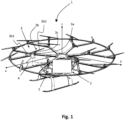
- FIG 1 shows an aircraft 1 in the form of a multi-rotor VTOL aircraft as produced by the applicant.
- Aircraft 1 comprises an onboard flight controller 2 for controlling a plurality of, e.g., 18 electrically powered propulsion units 3, each propulsion unit at least comprising an electric motor 3a and a (preferably monolithic) rotor 3b, said rotor 3b having two rotor blades 3b1, 3b2 attached to a bearing 3c, as will be described with reference to Figures 2 through 8 .
- element 3c will also be referred to as "hub”.
- only one propulsion unit 3 and its components are explicitly denoted in Figure 1 .
- Reference numeral 4 denotes an exemplary sensor unit for measuring a current state of aircraft 1 and/or of propulsion unit 3.
- Reference numeral 5 denotes means for pilot input into flight controller 2 for steering the aircraft 1.
- Sensor unit 4 and propulsion units 3 are operatively connected in communication with flight controller 2, as depicted.
- Reference numerals x, y, and z denote the aircraft's main control axes, i.e., roll, pitch, and yaw.
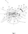
- FIG. 2 shows a general view of a bearing 3c and a driving assembly designed on the principles of the invention.
- the rotor blades 3b1, 3b2 (which need not be separate elements but could form integral parts of a one-piece monolithic rotor) are attached to a teeter beam 3d by means of stud bolts 3e that are denoted only on one side of the arrangement.
- Reference numeral RA denotes the rotational axis of the assembly.
- the teeter beam 3d comprises a central portion or main body 3da arranged on said rotational axis, said central portion 3da having at least one fixing structure for attaching said rotor 3b, i.e., by means of said bolts 3e.
- the teeter beam 3d further comprises, departing from said central portion 3da, two arms 3db that extend outwardly in opposite radial directions with respect to said rotational axis RA.
- a hub piece 3f that is devised for connection to a driving shaft of a (generic) motor 3a.
- Hub piece 3f has two arms 3g1, 3g2 (driving arms) that extend beyond said main body 3da of teeter beam 3d with respect to the rotational axis RA.
- a retainer piece 3h Above teeter beam 3d there is located a retainer piece 3h.
- Hub piece 3f and retainer piece 3h are connected along the rotational axis RA by means of a central or failsafe pin 3i, as will become more apparent from Figure 3 .
- Teeter beam 3d is supported via respective pairs of (first) lugs 3j1, 3j2 at its two ends, i.e., on said arms 3db, between which are arranged respective (second) lugs 3k located at the ends of said arms 3g1, 3g2 of hub piece 3f. Sandwiched between lugs 3j1 and 3k viz.
- lugs 3k and 3j2 are elastomeric bushings 3l1, 3l2 such that an axis passing through a centre of each of the two lugs 3k forms a teeter pivot or teeter axis TA for the rotor blades 3b1, 3b2, and any angular deflection about this teeter axis TA compresses the bushing, e.g., bushing 311 on one side of the teeter axis and reduces compression on the bushing, e.g., bushing 3l2 on the other side of the teeter axis TA, and vice versa.
- the bushing e.g., bushing 311 on one side of the teeter axis and reduces compression on the bushing, e.g., bushing 3l2 on the other side of the teeter axis TA, and vice versa.
- elastomeric bushings are described as a non-limiting example for elastic bushings.
- the hub piece may have pairs of lugs at the respective ends of said arms, and the lugs of the teeter beam could be sandwiched between the respective pairs of lugs of the hub piece.
- Appropriate changes would then apply for the arrangement of the elastic (or elastomeric) bushings, as readily understood by those skilled in the art.
- a spacing between inner faces of the lugs 3j1, 3j2, 3k is selected to provide a desired amount of pre-compression to the bushings 311, 3l2 to ensure that, in operation, and when deflected by teeter oscillation and loaded by torque and lift loads, that they remain in compression. They are fitted between the lugs 3j1, 3j2, 3k by being compressed into the available gap or spacing on assembly.
- This lug 3k provides a direct load path into the hub and is structurally more efficient and uses less material than an alternative configuration with the single lug at the ends of the teeter beam.
- Second Lugs 3k are aligned with first lugs 3j1, 3j2 of teeter beam 3d for receiving connecting or teeter pins 3n, as will become more apparent from Figures 4 and 5 .
- Lugs 3j1, 3j2 and 3k are angled with respect to the rotational axis RA, in particular by an angle of approximately 30° to 35° as will become particularly apparent from Figure 3 . As stated before, this angle only applies to a powered rotor, while an unpowered rotor, such as that on a gyroplane, would not benefit from this. For an unpowered rotor, the angle would preferably be 0°, and teeter beam 3d and hub piece 3f would be aligned.
- Connecting pins 3n comprises a screw head 3o on one end and threadedly engage a screw nut 3p at their other end.
- the primary load path through the assembly is from the driven part of the hub or hub piece 3f via the two driving arms 3g1, 3g2 on this component, to said pair of connecting pins 3n passing through the axes of the elastomeric bushings 3l1, 3l2 and then to the pair of lugs 3j1, 3j2 which directly load the teeter beam 3d and hence the attached rotor blades 3b1, 3b2.
- Between the retainer piece 3h and the driven part of the hub (hub piece 3f) passes said failsafe pin 3i along the axis of rotation of the rotor (i.e., rotational axis RA) which provides a direct load path between the driven part of the hub (hub piece 3f) and the retainer piece 3h.
- any failure of a component within the primary load path results in a resultant relative motion of the teeter beam 3d to the failsafe pin 3i, and so the failsafe pin 3i reacts any radial loading directly, while the retainer piece 3h reacts lift loads via the failsafe pin 3i.
- the failsafe pin 3i is thus trivially loaded in normal operation but is so configured to carry the full flight loads in the event of failure of any primary load path component.
- the rotor 3b i.e., the individual rotor blades 3b1, 3b2, has (each have) a leading edge LE and a trailing edge TE in relation to a sense of rotation SR of the rotor.
- Reference numeral RA' denotes the rotor axis, which must not be confounded with aforementioned rotational axis RA.
- At right angles with respect to said rotor axis RA' lies so-called normal axis NA.
- teeter axis TA is rotated in negative direction by an angle ⁇ , ⁇ ⁇ 0°, i.e., toward said trailing edge TE (negative skew angle). This is different than in known (active) teeter bearings, where ⁇ > 0°.
- a negative rotation of the teeter axis TA i.e., with ⁇ ⁇ 0°, preferably -60° ⁇ cp ⁇ - 30°, may generate a preferred lift vector in the case of a multirotor aircraft of the type shown in Figure 1 .
- Alternative embodiments of the present invention comprise a teeter axis TA that is rotated in positive direction, ⁇ > 0°, i.e., toward said leading edge LE, with respect to said neutral axis NA of the rotor.
- the design shown in Figure 2 achieves a lift vector with a reduced backward tilt in a direction opposite the direction of flight, while keeping the rotor stable aerodynamically, which may lead to a power reduction in forward flight.
- the air stream comes either from a head-on direction along rotational axis RA (e.g., for propeller airplanes) or from the side (e.g., for helicopters, as shown in Figure 2 ), the present description further comprises a novel design of an aerodynamically stable rotor with negative rotation of the teeter axis.
- the design shown in Figure 2 includes a failsafe function, as previously described, which is fulfilled by said retainer piece (or fail-safe retainer) 3h clamped in place by the failsafe pin 3i and positioned above teeter beam 3d.
- the fail-safe retainer 3h carries two buffer components (cf. Figure 7 ) in close clearance with the top of the teeter beam 3d which provide a teeter pivot in the event of a primary load path failure.
- hub 3c is shown mounted on a generic electric motor 3a although it can be mounted on a conventional rotorcraft gearbox or other source of power delivery to a motor shaft.
- the hub 3c is shown with a monolithic two-blade rotor 3b.
- the use of such a rotor removes the need for the hub to carry blade root bending moments and so allows a lighter connecting structure to the teeter beam.
- Use of rotors with separate blades 3b1, 3b2 is equally possible, however.
- Figure 3 illustrates failsafe pin 3i layout showing retention of the hub or bearing 3c in case of drive shaft or bearing failure.
- the failsafe pin 3i is extended through a hollow drive shaft 3aa of a motor (not shown) and is retained at its lower end by means of a screw head 3ia against a failsafe cap 3ib that closes a lower opening of the drive shaft 3aa.
- a screw nut 3q engaging a threaded portion of the failsafe pin 3i.
- the shaft 3aa is prevented from departure by the failsafe cap 3ib acting to prevent shaft pull-out.
- the upper end of the failsafe pin 3i (with screw nut 3q) clamps the failsafe retainer 3h against a cylindrical spacing sleeve 3ic that extends between hub piece 3f and failsafe retainer 3h and so reacts any lift loads from the rotor 3b directly to the failsafe cap 3ib via the failsafe pin 3i.
- Figure 3 further shows teeter stops that are arranged in the form of a teeter (stop) sleeve 3r (angled sleeve or shaped sleeve) of essentially conical shape acting on the internal surface of a bore 3dc through a centre of the teeter beam 3d.
- Teeter sleeve 3r by way of its conical form, allows and limits a teetering motion of rotor 3b.
- the rotor 3b also has a central bore 3ba to allow the resulting hollow spigot 3dd in the teeter beam 3b to pass through.
- an apex or tip of teeter sleeve 3r is in contact with hub piece 3f while a base of teeter sleeve 3r is in contact with failsafe retainer 3h.
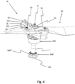
- Figure 4 shows an overall view of hub or bearing 3c without motor casing. This overall view shows bearings 3ab, 3ab' for shaft 3aa.
- the failsafe cap 3ib is of greater diameter than the lower bearing 3ab' and, if required to perform a retaining function during a failure event, will be retained by contact with a lower bearing housing 3ab". To be effective, the failsafe cap 3ib therefore needs to be of greater diameter than the smallest fixed bore surrounding the shaft 3aa.
- the monolithic rotor 3b is shown retained by two bolts 3e. In the event of a bolt failure the rotor 3b is still retained via the bore 3ba ( Figure 3 ) around the spigot 3dd ( Figure 3 ) on the teeter beam 3d. This bore 3ba surrounds the teeter stop sleeve 3r ( Figure 3 ) which is mounted on the failsafe pin 3i.
- FIG. 5 shows a detail of the bushing assembly.
- the teeter or connecting pins 3n are devised as simple bolts passing through a pair of first lugs 3j1, 3j2 at each end of the teeter beam 3d.
- the hub piece 3f carries a single second lug 3k at each side, which second lug 3k is placed between said first lugs 3j1, 3j2 and the elastomeric bushings 3l1, 3l2 (cf. Figure 2 ).
- Said elastomeric bushings 3l1, 3l2 are devised in the form of truncated cones, preferably with a respective base being in contact with said hub piece (second lug 3k).
- the elastomeric bushings 3l1, 3l2 are pre-compressed by means of the connecting pins 3n, or the bushings can be pre-compressed by forcing them between two lugs that are a fixed, defined distance apart, i.e., outer (first) lugs 3j1, 3j2 on the one hand and inner (second) lug 3k on the other hand.
- FIG. 6 which shows a section through the bushing assembly
- a fitted tubular spacer 3m is passed through the two elastomeric bushings 3l1, 3l2 for each pair of said first lugs 3j1, 3j2 and bears on each of said two first lugs 3j1, 3j2 to react compression from the connecting pin 3n.
- second lug 3k comprise a recessed portion surrounding a lug through-hole for positioning of bushing 3l1, 3l2.
- Teeter pin 3n is devised as a simple bolt passing through the teeter beam lugs (first lugs 3j1, 3j2) and the hub lug (second lug 3k).
- the bushings 3l1, 3l2 are compressed by forming the teeter beam lugs (first lugs 3j1, 3j2) and the hub lug (second lug 3k) with a correct spacing or gap to produce the desired pre-compression when the bushings 3l1, 3l2 are compressed and slid between the lugs 3j1, 3j2, 3k on installation.
- said fitted tubular spacer 3m is arranged as previously described.
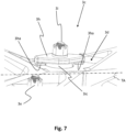
- Figure 7 provides details of the failsafe retainer 3h and corresponding buffers.
- the failsafe retainer 3h is clamped against the spacing sleeve 3ic (cf. Figure 3 ) mentioned earlier. It performs a retaining function in a failsafe situation and carries on its underside a pair of buffer protrusions 3ha in close clearance with the top of the teeter beam 3d.
- These buffer protrusions 3ha provide vertical constraint in the event of any primary load path failure of the hub or shaft. They are aligned in azimuth with the teeter axis TA (cf. Figure 2 ) to preserve the correct teeter axis TA after primary load path failure and so to ensure consistent rotor behaviour.
- Figure 8 shows non-linear elastomeric bushings, which can be used in the present invention.
- Elastomeric bushings as so far described tend to naturally exhibit non-linear elastic behaviour. In an oscillatory situation this can be highly advantageous as a means to prevent uncontrolled resonance.
- Natural frequency of oscillation is a function of the mass restrained by an elastic element and the elastic stiffness of the constraint. A given mass and stiffness having a specific set of frequencies. Introducing non-linear stiffness, i.e., a non-linear force or moment-deflection characteristic results in each amplitude having a different natural frequency. The effect is to limit the amplitude of oscillation at a fixed frequency. This is referred to as "limit cycle oscillation", or LCO.
- elastomeric bushings EB (such as bushings 3l1, 3l2 shown earlier) are placed between two supporting surfaces SS (such as first lugs 3j1, 3j2 shown earlier) that are part of or attached to the same component (e.g., said teeter beam 3d).
- Another component AC (such as second lug 3k shown earlier) is placed between the two bushings EB and is thus constrained by the bushings EB and can deflect in rotation about an axis normal to the axis of the bushings.
- the assembly is held together (pre-compressed) by means of connecting pin CP (such as pin 3n shown earlier).
- Drawing “B” shows the assembly with a small rotational deflection of component AC.
- “a” indicates that the edge of the contact area of the upper bushing EB' has moved towards the edge of component AC on the side of the bushing EB' that has been further compressed by the deflection. The centre of pressure of the bushing EB' has thus also moved towards the edge of component AC on that side.
- "b” indicates that the edge of the contact area of the upper bushing EB' on the side experiencing reduced compression due to the deflection has moved away from the edge of component AC, and with a corresponding shift of the centre of pressure on that side has also moved away from the edge of component AC. Similar behaviour can be observed on the lower bushing EB. The result is that the reacting moment on component AC increases in a non-linear manner with deflection.
- Drawing “C” shows the same assembly with a much greater degree of deflection.
- "c” indicates the extreme edge of the upper bushing EB'. With this level of deflection component AC now makes contact at the extreme edge of the bushing EB' and so the maximum moment arm is achieved.
- the part of the bushing directly above the outside edge of component AC at "c” has a very short vertical extent between components SS and AC. This is directly equivalent to a very short spring element. For a given stiffness and cross-sectional area, any linear elastic material will produce a higher stiffness if the component it comprises is of smaller dimension in the direction of the applied load, this short vertical extent therefore results in a stiffness that increases rapidly as the bushing is further compressed between components SS and AC.
- Drawing “D” shows a typical torque-deflection curve for a bushing as described in connection with drawings “A” through “C”.
- “deflection” horizontal axis refers to rotational movement of component AC with respect to component SS.
- the curve is approximately linear with a point of inflexion at zero deflection.
- the curve becomes steeper.
- a vertical curve would indicate infinite stiffness and a very steep curve at this point fully replaces a separate teeter stop (cf. above) when applied to a rotor hub.
- the assembly is also shown with component SS fixed and component AC moving. Another possible approach is with component AC fixed and component SS moving.
Description
- The invention relates to an elastic teeter bearing for a rotor, particularly in an aircraft, according to
claim 1. - The invention further relates to a driving arrangement for driving a rotor in an aircraft, according to claim 17.
- The invention also relates to an aircraft with at least one propulsion unit comprising a rotor, in particular a multi-rotor VTOL aircraft with distributed electrically powered propulsion units, at least some of which comprise a rotor, according to claim 18.
- Many existing rotorcraft, i.e., aircraft lifted or propelled by means of propellers or rotors use teetering rotor hubs with elastomeric bearings. Existing hubs of this kind use laminated elastomeric torsion bearings which are subject to intensive wear effects which significantly limit the lifetime of such bearings. Existing teetering rotor hubs use elastomeric teeter bearings which place the elastomeric elements primarily in shear under deformation induced by teeter oscillations of the rotor blades.
- Furthermore, known teetering rotor hubs are vulnerable to catastrophic outcomes from single structural or mechanical faults. Although these units are well proven in service, a single structural failure of a primary load path can result in the loss of control of, or the release of the rotor. Relevant prior art teachings are disclosed in
EP3345830A1 ,US3288226A andUS2010038469A1 . - There is a need for a lightweight, low maintenance and simple failsafe teetering rotor hub suitable for both powered and unpowered rotors, e.g., for an aircraft or for a gyroplane. Currently, these all use two blade teeter rotors with cyclic pitch adjustment achieved by direct control of the rotor rotational axis. As used herein, an unpowered rotor is a rotor that has no applied torque to the shaft (unlike a wind turbine wherein the generator applies a reaction torque to the shaft).
- There is also a need for an aircraft equipped with such a lightweight, low maintenance and simple failsafe teetering rotor hub.
- It is the object of the invention to satisfy these needs.
- According to the invention, the object is achieved by means of a bearing as defined in
claim 1, by means of the arrangement as defined in claim 17, and by means of an aircraft as defined in claim 18. Advantageous further embodiments are defined in the dependent claims. - According to a first aspect of the invention, an elastic teeter bearing for a rotor, particularly in an aircraft, comprises, rotatably arranged on an rotational axis of said rotor:
- a teeter beam, configured for attaching thereto a rotor having at least two rotor blades, either as separate blade parts or in one piece (i.e., monolithic), said teeter beam being devised for performing a teetering motion with respect to said rotational axis and having at least two first lugs or two pairs of first lugs arranged at opposite ends thereof at a distance with respect to said rotational axis;
- a hub piece located below said teeter beam, said hub piece having at least two arms that extend outwardly in a radial direction with respect to said rotational axis, each of said arms having a second lug, in case said teeter beam has said two pairs of first lugs, or having a pair of second lugs, in case said teeter beam has said two first lugs, arranged at said distance with respect to said rotational axis;
- wherein each one of said second lugs is located between the two lugs of a respective pair of first lugs or wherein each one of said first lugs is located between the two lugs of a respective pair of second lugs, and respective connecting pins pass through said first and second lugs on either side of said rotational axis; and
- wherein a pair of elastic bushings, i.e., bushings made from an elastic material, e.g., elastomers like polyurethane, natural rubber, butyl rubber or cushions made from metal, are arranged on each of said connecting pins between a first one of said first lugs and said second lug and between a second one of said first lugs and said second lug, respectively, or vice versa (i.e., if there are pairs of second lugs and only single first lugs arranges therebetween).
- Teeter bearings are known, in particular, from helicopters. Such teeter bearings generally comprise an active control of the rotor blade pitch angle. The present invention, on the other hand, may advantageously relate to a so-called "fixed pitch" configuration, wherein the teeter bearing allows some rotation of the rotor blades, this rotation being passive, i.e., uncontrolled (or not actively controlled), which may differentiate embodiments of the present invention from known (helicopter) teeter bearings.
- According to a second aspect of the invention, a driving arrangement for driving a rotor in an aircraft comprises the bearing according to an embodiment of the invention, said bearing having a central pin extending along said rotational axis, through said hub piece and said teeter beam, which central pin is devised for fixing a relative position of said hub piece and said teeter beam on said rotational axis, and further comprises a motor, preferably an electric motor, said motor comprising a hollow drive shaft, which drive shaft is connected to said hub piece for rotatably driving same, wherein said central pin extends coaxially through said drive shaft, wherein preferably said screw head according to an embodiment of the inventive bearing abuts on a terminal cap (failsafe cap) of said drive shaft.
- According to a third aspect of the invention, an aircraft with at least one propulsion unit comprises a rotor, in particular multi-rotor VTOL aircraft with distributed electrically powered propulsion units, at least some of which comprise a rotor, wherein said at least one rotor comprises a bearing or the driving arrangement according to the invention, wherein at least two rotor blades of said at least one rotor are attached to a teeter beam of said bearing on opposing sides thereof, wherein preferably said hub piece is connected to a drive shaft of a motor comprised in said at least one propulsion unit.
- The teetering pivot of the current invention uses simple elastic bushings mounted on a pin, i.e., said connecting pin (also referred to as teeter pin). The teetering axis is normal to the pin axis and the elastic bushings are primarily loaded in compression resulting in an intrinsically long fatigue life with a very simple and low-cost elastic component.
- The teeter pins may advantageously be angled relative to the rotational axis of the rotor while remaining normal to the teetering axis to align with the resultant force vector due to the driving torque applied to the rotor and the lift produced by the rotor in a selected operational condition. These features ensure that most of the load seen by the bushings is along the axis of symmetry of the bushing with only teetering producing a moment load over the face of the bushing. This further ensures that stress oscillations within the bushing due to teetering produce the minimum possible stress amplitude and hence a long fatigue life.
- The invention also incorporates, in a preferred further embodiment thereof, which embodiment is potentially independent from said first aspect of the invention, a central retaining pin (or failsafe pin) that is trivially loaded in normal use but, in the case of most single failures of any other element of the hub, will both retain and constrain the rotor within positional limits relative to the hub piece that preserve its function as a rotor. Other than a primary rotor shaft failure, a complete failure of the torque-reacting elements of the hub will result in the retention and constraint of the rotor but without the continuation of power delivery to the rotor.
- Prior art in this respect does not, to the knowledge of the applicant, include fail-safe features, thus resulting in potential catastrophic results arising from the failure of individual hub elements. Such damage may be due to cyclic loading induced fatigue or from single impact events such as bird strike.
- In a further preferred embodiment, a shaped sleeve is fitted over the central fail-safe pin and, in conjunction with a bore through which it passes within the teeter beam, provides a limiting stop for teetering motion. Said sleeve may be made from a material particularly suited to resisting impact loading, e.g., nylon, fabric reinforced phenolic resin, or an elastomer such as rubber or polyurethane, etc.
- The current invention uses simple elastic bushings and preferably places them under some pre-compression. In a corresponding embodiment of the bearing according to the present invention the bushings are pre-compressed by means of the connecting or teeter pins
- Teeter deflections then either increase or reduce the degree of compression of the bushings but do not place any part of the bushings in tension. As crack growth is primarily due to tensile loading, this compressive loading inhibits the growth of fatigue cracks within the bushings and results in the potential for a long service life with resulting low maintenance costs.
- To achieve this, in another preferred embodiment the connecting pins comprise means for compressing said bushings, in particular screwing means, said screwing means comprising a screw head, a threaded end portion opposite said screw head, and a screw nut engaging said threaded end.
- Furthermore, preferably each connecting pin has an outer thread at a second end that threadedly engages a screw nut. This provides an easy way to ensure almost any desirable amount of (pre-)compression.
- While the bearing according to an embodiment of the invention can be devised so that the elastic bushings are pre-compressed by means of the connecting pins, the bushings can also be pre-compressed by forcing them between two lugs that are a fixed, i.e., placed at a fixed relative distance, which distance is smaller than a corresponding dimension of a respective bushing.
- In another preferred embodiment of the bearing according to the invention the elastic bushings are devised in the form of truncated cones, preferably with a respective base of said cones being in contact with said hub piece. Applicant has found that this configuration provides the best effects as far as the teetering behaviour of the bearing and its wear resistance are concerned. However, there are situations where it is preferred to arrange the bushings differently, e.g., the other way around. If the narrow end or tip (apex) of said cones is against the central (or second) lug (i.e., the hub piece) then stiffness will be lower than with the base against said lug.
- However, other forms can be considered for the bushings as well: There is an advantage in configuring the bushings to generate a defined non-linear characteristic with deflection. If a piece of elastic material resting on a solid surface is compressed against that surface then, as the compression is increased, the ultimate stiffness will be that of the surface against which the elastic material is compressed. If the piece of elastic material is shaped correctly, any selected load/deflection characteristic can be achieved. This is also true of the bushings in this application.
- Problems of oscillatory resonance are very common in rotorcraft. With any spring-mass system, the natural (Eigen) frequency is a direct function of the force-deflection gradient of the spring element. If a non-linear spring is used, then at each deflection amplitude, the resonant frequency has a unique value. If excited by an external oscillatory force, then oscillation cannot build as any increase in amplitude results in a changed natural frequency and unless the excitation frequency changes to track this change in natural frequency, the excitation becomes ineffective. This constitutes an important feature of the concept of the use of elastic bushings in the present invention.
- Therefore, the shaping of the bushings to achieve a selected non-linearity can be used in embodiments of the present invention together with the inherently non-linear elastic behaviour of such bushings when loaded in compression. Using, e.g., finite element methods, one could define a custom form for the bushings for a specific use.
- Alternatively or additionally, one could also modify a shape or structure of said surface in order to achieve a desired load/deflection characteristic for the bushings.
- In another embodiment of the bearing according to the invention said hub piece is rotated with respect to the teeter beam around said rotational axis. Such an arrangement is particularly well suited for powered rotors, e.g., in an aircraft.
- In a highly advantageous embodiment of the bearing according to the invention said first and second lugs, i.e., the respective bores or through-holes comprised therein and accordingly also said connecting pins are angled at 15° to 50°, preferably 20 to 40°, most preferably 30 to 35°, with respect to said rotational axis. This helps to achieve the above-mentioned compressional load on the bushings, since this configuration ensures that the resultant force induced by the normal driving torque on the rotor and the induced lift passes along the axis of each connecting pin. This reduces shearing loads on the elastic bushings and so reduces the potential for progressive damage due to deformation other than compression within the bushings.
- Therefore, according to a further embodiment, said connecting pins are obliquely oriented with respect to said rotational axis, wherein preferably said connecting pins are obliquely oriented relative to said rotational axis in symmetrical fashion.
- Such an embodiment serves to align the bushing axis with the resultant force arising from the driving torque and the rotor lift and is dictated entirely by the relative magnitude of these two forces at the bushing axis radius from the rotor axis and a selected design operating condition. The range could therefore, in principle, comprise any angle between 0° and 90°. For an unpowered rotor (a gyroplane for example), the angle would advantageously be 0°.
- Therefore, in a corresponding further embodiment of the invention said hub piece is aligned with respect to the teeter beam, in particular in the case of an unpowered rotor.
- In a corresponding further embodiment of the bearing according to the invention, said teeter beam comprises a central portion arranged on said rotational axis, said central portion having at least one fixing structure for attaching said rotor, said teeter beam further comprising, departing from said central portion, two arms that extend outwardly in opposite radial directions with respect to said rotational axis, each of said arms comprising one of said pairs of first lugs arranged at said distance with respect to said rotational axis. This leads to a particularly simple and lightweight design of the bearing, which design requires a lower number of individual elements when compared with alternative designs.
- In yet a further embodiment of the bearing according to the invention, a fitted tubular spacer is passed through the two elastic bushings for each pair of said first lugs and bears on each of said two first lugs. Said spacer reacts compression from the corresponding connecting pin and may be a simple way to limit the loading of the elastic bushings, if it is of inferior length when compared with a corresponding dimension of the bushings.
- In yet a further embodiment of the bearing according to the invention, said first lugs and/or said second lugs comprise a recessed or a protruding portion surrounding a lug through-hole. This recessed or protruding portion can be used to surround part of the bushings for defining a positioning thereof.
- In order to provide failsafe behaviour, in a further embodiment the bearing according to the invention further comprises a central pin (or failsafe pin) extending along said rotational axis, through said hub piece and said teeter beam, which central pin is devised for fixing a relative position of said hub piece and said teeter beam on said rotational axis. If lift load path integrity is compromised by a structural failure, the teeter beam may become free to move in the direction of the lift force relative to the central failsafe pin. In this event, the motion is arrested by means of said central pin and lift forces are then transmitted to a driven part of the hub directly by the failsafe pin. In this way, catastrophic failure of the bearing is prevented in a sense that a failsafe constraint prevents the rotor from developing adverse behaviour after a failure including failure of the bearing.
- It should be noted that providing said central pin (or failsafe pin), as introduced in claim 13, can also be done separately from providing the additional features of
claim 1, in particular said elastic bushings. Said feature (i.e., the failsafe pin) and any other feature depending thereon is not limited to the specific embodiments as defined in the preceding claims. - In order to enable and restrict a teetering motion of the teeter beam, in a further embodiment of the bearing according to the invention said bearing further comprises an angled sleeve (shaped sleeve or teeter stop sleeve) around said central pin extending through an opening in said teeter beam, said angled sleeve preferably having the form of a (doubly) truncated cone, a maximum diameter of which is in close clearance with an inner diameter of said opening. Most preferably, said hub piece abuts on an end of said angled sleeve, most preferably on an apex thereof. In this way, the outer inclined cone surfaces permit and restrict said teetering motion. It is undesirable to have constant contact due to wear considerations. It is preferred that the flanks of the conical parts should touch the bore evenly when the maximum teeter amplitude is reached. Close clearance is desirable for fail safety as it provides radial constraint to the rotor in a failsafe situation. The clearance between this angled sleeve and the inside of the bore or opening defines the radial constraint in the event of primary load path failure. Alternatively or additionally, a teeter stop could also be provided as an abutment element below the rotor blades in order to limit a teetering motion.
- Providing a double cone (or two cones) may help to spread the load over a greater surface area, thus reducing wear and increasing lifetime.
- In a further embodiment, the bearing according to the invention further comprises a spacing sleeve around said central pin extending through said opening in said teeter beam inside and through said angled sleeve. An upper end of the failsafe pin advantageously clamps the teeter beam against said spacing sleeve and so reacts any lift loads from the rotor directly via the failsafe pin, thus providing enhanced safety.
- In a further embodiment aimed in the same direction, the bearing according to the invention comprises a retainer piece arranged on said central pin at a first end thereof, said first end being located on a side of said teeter beam opposite from said hub piece. In this way, said upper end of the failsafe pin advantageously clamps said retainer piece against said spacing sleeve and so reacts any lift loads from the rotor via the failsafe pin, thus providing further enhanced safety.
- In order to ensure this functioning, said retainer piece may be clamped, in a further embodiment of the bearing according to the invention, against said spacing sleeve and/or said angled sleeve, preferably by devising said central pin with a screw head at one end thereof and with a threaded portion that engages a screw nut at the other end thereof, said screw nut most preferably being in contact with said retainer piece.
- Preferably, in a further embodiment of the bearing according to the invention said retainer piece has at least one, preferably two buffer protrusions in close clearance with said teeter beam, which in the case of two such protrusions are aligned in azimuth with a teeter axis. The retainer piece (or failsafe retainer) is preferably clamped against the spacing sleeve mentioned earlier. It performs a retaining function in a failsafe situation. Similarly, it may carry a pair of buffer protrusions in close clearance with the top of the teeter beam. These provide vertical constraint in the event of any primary load path failure of the hub or an associated driving shaft (cf. below). They are preferably aligned in azimuth with the teeter axis to preserve the correct teeter axis after primary load path failure and so to ensure consistent rotor behaviour.
- In this way, said failsafe constraint may be provided (jointly) by the failsafe pin (constrains the teeter stop sleeve), the retainer piece (and the buffer features below the retainer piece, vertical constraint) and the teeter stop sleeve (radial constraint within operating limits).
- A surface coating, or treatment on the mating faces of the teeter beam and said buffer projections may constitute an advantageous further embodiment as they experience some relative sliding motion. They need to last long enough in a fail-safe situation to allow the aircraft to land safely. Amorphous diamond, which is extremely hard, very tough and has very low friction, can be an appropriate treatment for aluminum alloys in this situation. However, the invention is not limited in this respect.
- In yet another, highly preferred embodiment of the bearing according to the invention, a teeter axis is rotated by an angle ϕ, ϕ > 0° or ϕ < 0°, preferably in the range -60° < ϕ < -30°, with respect to a normal axis of the rotor, which normal axis is oriented at right angles with respect to a rotor axis.
- Generally, the rotor, i.e., the individual rotor blades has (have) a leading edge and a trailing edge in relation to a sense of rotation of the rotor. The rotor also has a rotor axis, which must not be confounded with the rotational axis (of the motor). At rights angles with respect to said rotor axis lies so-called normal axis. With respect to said normal axis, the teeter axis of known (active) teeter bearings is rotated in positive direction by an angle ϕ, ϕ > 0°.
- A range of skew angles were explored analytically by the applicant and the results for a negative skew angle (cp < 0°) were surprising and of great interest. Accordingly, this configuration was designed as a physical specimen and tested.
- Wind tunnel experiments confirmed that a negative rotation of the teeter axis, i.e., with ϕ < 0°, preferably -60° < ϕ < -30°, generates a preferred lift vector in the case of a rotor without cyclic-control, which is a preferred use case of the present invention. Alternative embodiments of the present invention therefore comprise a teeter axis that is either rotated in positive direction or (preferably) to in negative direction with respect said neutral axis of the rotor.
- This may generate a lift vector with a reduced backward tilt in a direction opposite the direction of flight, while keeping the rotor stable aerodynamically, which may lead to a power reduction in forward flight.
- Thus, the present description further comprises a novel design of an aerodynamically stable rotor with negative rotation of the teeter axis, which is potentially independent from the described elastic bushings and/or the failsafe design.
- Use of the present invention is by no means limited to aircraft but can be extended to all kinds of rotors (powered or not) that are subject to a teetering motion, e.g., in wind energy turbines, gyroplanes, etc.
- Additional features and advantages of the invention will become apparent from the following description of exemplary embodiments with reference to the attached drawings.
- Fig. 1
- shows an aircraft which can make use of the present invention;
- Fig. 2
- shows a general perspective view of a driving arrangement comprising an elastic bearing or hub designed on the principles of the invention;
- Fig. 3
- shows a section through the centre of the bearing or hub of
Fig. 2 ; - Fig. 4
- shows a further perspective view of the bearing or hub of
Fig. 2 ; - Fig. 5
- shows a detail of the bearing of
Fig. 2 ; - Fig. 6
- shows a section through a connecting pin assembly comprised in the bearing or hub of
Fig. 2 ; - Fig. 7
- shows a detail of the bearing of
Fig. 2 ; and - Fig. 8
- shows the behaviour of an elastic bushing as used in the present invention.
-
Figure 1 shows anaircraft 1 in the form of a multi-rotor VTOL aircraft as produced by the applicant.Aircraft 1 comprises anonboard flight controller 2 for controlling a plurality of, e.g., 18 electrically poweredpropulsion units 3, each propulsion unit at least comprising an electric motor 3a and a (preferably monolithic)rotor 3b, saidrotor 3b having two rotor blades 3b1, 3b2 attached to abearing 3c, as will be described with reference toFigures 2 through 8 . In the following,element 3c will also be referred to as "hub". For reason of clarity, only onepropulsion unit 3 and its components are explicitly denoted inFigure 1 .Reference numeral 4 denotes an exemplary sensor unit for measuring a current state ofaircraft 1 and/or ofpropulsion unit 3.Reference numeral 5 denotes means for pilot input intoflight controller 2 for steering theaircraft 1.Sensor unit 4 andpropulsion units 3 are operatively connected in communication withflight controller 2, as depicted. Reference numerals x, y, and z denote the aircraft's main control axes, i.e., roll, pitch, and yaw. -
Figure 2 shows a general view of abearing 3c and a driving assembly designed on the principles of the invention. The rotor blades 3b1, 3b2 (which need not be separate elements but could form integral parts of a one-piece monolithic rotor) are attached to ateeter beam 3d by means ofstud bolts 3e that are denoted only on one side of the arrangement. Reference numeral RA denotes the rotational axis of the assembly. Theteeter beam 3d comprises a central portion or main body 3da arranged on said rotational axis, said central portion 3da having at least one fixing structure for attaching saidrotor 3b, i.e., by means of saidbolts 3e. Theteeter beam 3d further comprises, departing from said central portion 3da, two arms 3db that extend outwardly in opposite radial directions with respect to said rotational axis RA. Belowteeter beam 3d there is located ahub piece 3f that is devised for connection to a driving shaft of a (generic) motor 3a.Hub piece 3f has two arms 3g1, 3g2 (driving arms) that extend beyond said main body 3da ofteeter beam 3d with respect to the rotational axis RA. Aboveteeter beam 3d there is located aretainer piece 3h.Hub piece 3f andretainer piece 3h are connected along the rotational axis RA by means of a central orfailsafe pin 3i, as will become more apparent fromFigure 3 .Teeter beam 3d is supported via respective pairs of (first) lugs 3j1, 3j2 at its two ends, i.e., on said arms 3db, between which are arranged respective (second) lugs 3k located at the ends of said arms 3g1, 3g2 ofhub piece 3f. Sandwiched between lugs 3j1 and 3k viz. lugs 3k and 3j2 are elastomeric bushings 3l1, 3l2 such that an axis passing through a centre of each of the twolugs 3k forms a teeter pivot or teeter axis TA for the rotor blades 3b1, 3b2, and any angular deflection about this teeter axis TA compresses the bushing, e.g., bushing 311 on one side of the teeter axis and reduces compression on the bushing, e.g., bushing 3l2 on the other side of the teeter axis TA, and vice versa. - Here and in the following, elastomeric bushings are described as a non-limiting example for elastic bushings.
- If the teeter beam has single lugs at its respective ends, which is an alternative design (not shown), then the hub piece may have pairs of lugs at the respective ends of said arms, and the lugs of the teeter beam could be sandwiched between the respective pairs of lugs of the hub piece. Appropriate changes would then apply for the arrangement of the elastic (or elastomeric) bushings, as readily understood by those skilled in the art.
- A spacing between inner faces of the lugs 3j1, 3j2, 3k is selected to provide a desired amount of pre-compression to the
bushings 311, 3l2 to ensure that, in operation, and when deflected by teeter oscillation and loaded by torque and lift loads, that they remain in compression. They are fitted between the lugs 3j1, 3j2, 3k by being compressed into the available gap or spacing on assembly. - Between the two bushings 3l1, 3l2 at each end is positioned said single (second)
lug 3k mounted directly on thehub piece 3f. Thislug 3k provides a direct load path into the hub and is structurally more efficient and uses less material than an alternative configuration with the single lug at the ends of the teeter beam. -
Second Lugs 3k are aligned with first lugs 3j1, 3j2 ofteeter beam 3d for receiving connecting or teeterpins 3n, as will become more apparent fromFigures 4 and5 . Lugs 3j1, 3j2 and 3k are angled with respect to the rotational axis RA, in particular by an angle of approximately 30° to 35° as will become particularly apparent fromFigure 3 . As stated before, this angle only applies to a powered rotor, while an unpowered rotor, such as that on a gyroplane, would not benefit from this. For an unpowered rotor, the angle would preferably be 0°, and teeterbeam 3d andhub piece 3f would be aligned. Connectingpins 3n comprises a screw head 3o on one end and threadedly engage ascrew nut 3p at their other end. - The primary load path through the assembly is from the driven part of the hub or
hub piece 3f via the two driving arms 3g1, 3g2 on this component, to said pair of connectingpins 3n passing through the axes of the elastomeric bushings 3l1, 3l2 and then to the pair of lugs 3j1, 3j2 which directly load theteeter beam 3d and hence the attached rotor blades 3b1, 3b2. Between theretainer piece 3h and the driven part of the hub (hub piece 3f) passes saidfailsafe pin 3i along the axis of rotation of the rotor (i.e., rotational axis RA) which provides a direct load path between the driven part of the hub (hub piece 3f) and theretainer piece 3h. Any failure of a component within the primary load path results in a resultant relative motion of theteeter beam 3d to thefailsafe pin 3i, and so thefailsafe pin 3i reacts any radial loading directly, while theretainer piece 3h reacts lift loads via thefailsafe pin 3i. Thefailsafe pin 3i is thus trivially loaded in normal operation but is so configured to carry the full flight loads in the event of failure of any primary load path component. - The
rotor 3b, i.e., the individual rotor blades 3b1, 3b2, has (each have) a leading edge LE and a trailing edge TE in relation to a sense of rotation SR of the rotor. Reference numeral RA' denotes the rotor axis, which must not be confounded with aforementioned rotational axis RA. At right angles with respect to said rotor axis RA' lies so-called normal axis NA. With respect to said normal axis NA, teeter axis TA is rotated in negative direction by an angle ϕ, ϕ < 0°, i.e., toward said trailing edge TE (negative skew angle). This is different than in known (active) teeter bearings, where ϕ > 0°. - A range of skew angles were explored analytically and the results for a negative skew angle were surprising and of great interest. Accordingly, this configuration was designed as a physical specimen and tested. Wind tunnel experiments confirmed that a negative rotation of the teeter axis TA, i.e., with ϕ < 0°, preferably -60° < cp< - 30°, may generate a preferred lift vector in the case of a multirotor aircraft of the type shown in
Figure 1 . Alternative embodiments of the present invention comprise a teeter axis TA that is rotated in positive direction, ϕ > 0°, i.e., toward said leading edge LE, with respect to said neutral axis NA of the rotor. - The design shown in
Figure 2 achieves a lift vector with a reduced backward tilt in a direction opposite the direction of flight, while keeping the rotor stable aerodynamically, which may lead to a power reduction in forward flight. - Taking into account that in known use cases with fixed pitch rotors, the air stream comes either from a head-on direction along rotational axis RA (e.g., for propeller airplanes) or from the side (e.g., for helicopters, as shown in
Figure 2 ), the present description further comprises a novel design of an aerodynamically stable rotor with negative rotation of the teeter axis. - The design shown in
Figure 2 includes a failsafe function, as previously described, which is fulfilled by said retainer piece (or fail-safe retainer) 3h clamped in place by thefailsafe pin 3i and positioned aboveteeter beam 3d. The fail-safe retainer 3h carries two buffer components (cf.Figure 7 ) in close clearance with the top of theteeter beam 3d which provide a teeter pivot in the event of a primary load path failure. - Note that in
Figure 2 thehub 3c is shown mounted on a generic electric motor 3a although it can be mounted on a conventional rotorcraft gearbox or other source of power delivery to a motor shaft. - The
hub 3c is shown with a monolithic two-blade rotor 3b. The use of such a rotor removes the need for the hub to carry blade root bending moments and so allows a lighter connecting structure to the teeter beam. Use of rotors with separate blades 3b1, 3b2 is equally possible, however. -
Figure 3 illustratesfailsafe pin 3i layout showing retention of the hub or bearing 3c in case of drive shaft or bearing failure. Thefailsafe pin 3i is extended through a hollow drive shaft 3aa of a motor (not shown) and is retained at its lower end by means of a screw head 3ia against a failsafe cap 3ib that closes a lower opening of the drive shaft 3aa. At the upper end, there is located a screw nut 3q engaging a threaded portion of thefailsafe pin 3i. In the event of complete drive shaft failure or the failure of shaft bearings (not shown), or the failure of hub retaining fixings 3fa that connect shaft 3aa tohub piece 3f, the shaft 3aa is prevented from departure by the failsafe cap 3ib acting to prevent shaft pull-out. The upper end of thefailsafe pin 3i (with screw nut 3q) clamps thefailsafe retainer 3h against a cylindrical spacing sleeve 3ic that extends betweenhub piece 3f andfailsafe retainer 3h and so reacts any lift loads from therotor 3b directly to the failsafe cap 3ib via thefailsafe pin 3i. -
Figure 3 further shows teeter stops that are arranged in the form of a teeter (stop)sleeve 3r (angled sleeve or shaped sleeve) of essentially conical shape acting on the internal surface of a bore 3dc through a centre of theteeter beam 3d.Teeter sleeve 3r, by way of its conical form, allows and limits a teetering motion ofrotor 3b. Therotor 3b also has a central bore 3ba to allow the resulting hollow spigot 3dd in theteeter beam 3b to pass through. In the shown exemplary embodiment, an apex or tip ofteeter sleeve 3r is in contact withhub piece 3f while a base ofteeter sleeve 3r is in contact withfailsafe retainer 3h. -
Figure 4 shows an overall view of hub or bearing 3c without motor casing. This overall view shows bearings 3ab, 3ab' for shaft 3aa. The failsafe cap 3ib is of greater diameter than the lower bearing 3ab' and, if required to perform a retaining function during a failure event, will be retained by contact with a lower bearing housing 3ab". To be effective, the failsafe cap 3ib therefore needs to be of greater diameter than the smallest fixed bore surrounding the shaft 3aa. - The
monolithic rotor 3b is shown retained by twobolts 3e. In the event of a bolt failure therotor 3b is still retained via the bore 3ba (Figure 3 ) around the spigot 3dd (Figure 3 ) on theteeter beam 3d. This bore 3ba surrounds theteeter stop sleeve 3r (Figure 3 ) which is mounted on thefailsafe pin 3i. -
Figure 5 shows a detail of the bushing assembly. The teeter or connectingpins 3n are devised as simple bolts passing through a pair of first lugs 3j1, 3j2 at each end of theteeter beam 3d. Thehub piece 3f carries a singlesecond lug 3k at each side, whichsecond lug 3k is placed between said first lugs 3j1, 3j2 and the elastomeric bushings 3l1, 3l2 (cf.Figure 2 ). Said elastomeric bushings 3l1, 3l2 are devised in the form of truncated cones, preferably with a respective base being in contact with said hub piece (second lug 3k). Around said first lugs 3j1, 3j2, i.e., around corresponding through-holes therein, there are protruding portions 3ja surrounding said lug through-holes for positioning of the bushings 3l1, 3l2. - The elastomeric bushings 3l1, 3l2 are pre-compressed by means of the connecting
pins 3n, or the bushings can be pre-compressed by forcing them between two lugs that are a fixed, defined distance apart, i.e., outer (first) lugs 3j1, 3j2 on the one hand and inner (second)lug 3k on the other hand. - As can be gathered from
Figure 6 , which shows a section through the bushing assembly, a fittedtubular spacer 3m is passed through the two elastomeric bushings 3l1, 3l2 for each pair of said first lugs 3j1, 3j2 and bears on each of said two first lugs 3j1, 3j2 to react compression from the connectingpin 3n. - As can be further gathered from
Figure 6 ,second lug 3k comprise a recessed portion surrounding a lug through-hole for positioning of bushing 3l1, 3l2. -
Teeter pin 3n is devised as a simple bolt passing through the teeter beam lugs (first lugs 3j1, 3j2) and the hub lug (second lug 3k). - As stated before, the bushings 3l1, 3l2 are compressed by forming the teeter beam lugs (first lugs 3j1, 3j2) and the hub lug (
second lug 3k) with a correct spacing or gap to produce the desired pre-compression when the bushings 3l1, 3l2 are compressed and slid between the lugs 3j1, 3j2, 3k on installation. - To ensure that the teeter beam lugs (first lugs 3j1, 3j2) are not strained in an uncontrollable manner, said fitted
tubular spacer 3m is arranged as previously described. -
Figure 7 provides details of thefailsafe retainer 3h and corresponding buffers. As shown, thefailsafe retainer 3h is clamped against the spacing sleeve 3ic (cf.Figure 3 ) mentioned earlier. It performs a retaining function in a failsafe situation and carries on its underside a pair of buffer protrusions 3ha in close clearance with the top of theteeter beam 3d. These buffer protrusions 3ha provide vertical constraint in the event of any primary load path failure of the hub or shaft. They are aligned in azimuth with the teeter axis TA (cf.Figure 2 ) to preserve the correct teeter axis TA after primary load path failure and so to ensure consistent rotor behaviour. -
Figure 8 shows non-linear elastomeric bushings, which can be used in the present invention. Elastomeric bushings as so far described tend to naturally exhibit non-linear elastic behaviour. In an oscillatory situation this can be highly advantageous as a means to prevent uncontrolled resonance. Natural frequency of oscillation is a function of the mass restrained by an elastic element and the elastic stiffness of the constraint. A given mass and stiffness having a specific set of frequencies. Introducing non-linear stiffness, i.e., a non-linear force or moment-deflection characteristic results in each amplitude having a different natural frequency. The effect is to limit the amplitude of oscillation at a fixed frequency. This is referred to as "limit cycle oscillation", or LCO. - There is an advantage to designing a specific non-linearity in certain situations. In the case of the teetering rotor hub described, a very low stiffness is desirable for normal operation. For a teetering rotor there is also a maximum anticipated desirable oscillatory amplitude that is usually defined by the position of the rotor teeter stops. These are usually a hard limit arranged separately from the teeter bearings. With a non-linear characteristic within an elastomeric bearing, the non-linearity can be used to replace the separate rotor teeter stops by introducing features that cause the stiffness of the bearing to increase rapidly towards the limit of the rotational deflection.
Figure 8 shows a generalized elastomeric assembly configured to achieve this. - Referring to drawing "A", elastomeric bushings EB (such as bushings 3l1, 3l2 shown earlier) are placed between two supporting surfaces SS (such as first lugs 3j1, 3j2 shown earlier) that are part of or attached to the same component (e.g., said
teeter beam 3d). Another component AC (such assecond lug 3k shown earlier) is placed between the two bushings EB and is thus constrained by the bushings EB and can deflect in rotation about an axis normal to the axis of the bushings. The assembly is held together (pre-compressed) by means of connecting pin CP (such aspin 3n shown earlier). - Drawing "B" shows the assembly with a small rotational deflection of component AC. "a" indicates that the edge of the contact area of the upper bushing EB' has moved towards the edge of component AC on the side of the bushing EB' that has been further compressed by the deflection. The centre of pressure of the bushing EB' has thus also moved towards the edge of component AC on that side. Simultaneously, "b" indicates that the edge of the contact area of the upper bushing EB' on the side experiencing reduced compression due to the deflection has moved away from the edge of component AC, and with a corresponding shift of the centre of pressure on that side has also moved away from the edge of component AC. Similar behaviour can be observed on the lower bushing EB. The result is that the reacting moment on component AC increases in a non-linear manner with deflection.
- Drawing "C" shows the same assembly with a much greater degree of deflection. "c" indicates the extreme edge of the upper bushing EB'. With this level of deflection component AC now makes contact at the extreme edge of the bushing EB' and so the maximum moment arm is achieved. In addition, the part of the bushing directly above the outside edge of component AC at "c" has a very short vertical extent between components SS and AC. This is directly equivalent to a very short spring element. For a given stiffness and cross-sectional area, any linear elastic material will produce a higher stiffness if the component it comprises is of smaller dimension in the direction of the applied load, this short vertical extent therefore results in a stiffness that increases rapidly as the bushing is further compressed between components SS and AC.
- Drawing "D" shows a typical torque-deflection curve for a bushing as described in connection with drawings "A" through "C". "deflection" (horizontal axis) refers to rotational movement of component AC with respect to component SS. At low deflections, the curve is approximately linear with a point of inflexion at zero deflection. As deflection is increased in either a positive or negative direction, the curve becomes steeper. At maximum deflection, the curve becomes very steep, a vertical curve would indicate infinite stiffness and a very steep curve at this point fully replaces a separate teeter stop (cf. above) when applied to a rotor hub.
- It must be noted that this is an example only and that the form of the bushings shown can be varied to produce any desired variation of stiffness with deflection. Component AC is depicted with a flat surface interaction with the bushings. This is not the only form possible and a non-planar surface, or a shaped feature of features on the interacting faces of component AC can be used to generate specific non-linear characteristics (cf. description above).
- The assembly is also shown with component SS fixed and component AC moving. Another possible approach is with component AC fixed and component SS moving.
Claims (18)
- Elastic teeter bearing (3c) for a rotor (3b), particularly in an aircraft (1), comprising, rotatably arranged on an rotational axis (RA) of said rotor (3b):a teeter beam (3d), configured for attaching thereto a rotor (3b) having at least two rotor blades (3b1, 3b2), either as separate blade parts or in one piece, said teeter beam (3d) being devised for performing a teetering motion with respect to said rotational axis (RA) and having at least two first lugs or two pairs of first lugs (3j1, 3j2) arranged at opposite ends thereof at a distance with respect to said rotational axis (RA);a hub piece (3f) located below said teeter beam (3d), said hub piece (3f) having at least two arms (3g1, 3g2) that extend outwardly in a radial direction with respect to said rotational axis (RA), each of said arms (3g1, 3g2) having a second lug (3k), in case said teeter beam (3d) has said two pairs of first lugs (3j1, 3j2), or having a pair of second lugs, in case said teeter beam (3d) has said two first lugs, arranged at said distance with respect to said rotational axis (RA);characterised in thateach one of said second lugs (3k) is located between the two lugs of a respective pair of first lugs (3j1, 3j2) or wherein each one of said first lugs is located between the two lugs of a respective pair of second lugs, and respective connecting pins (3n) pass through said first and second lugs (3j1, 3j2, 3k) on either side of said rotational axis (RA); andin that a pair of elastic bushings (3l1, 3l2) are arranged on each of said connecting pins (3n) between a first one of said pair of first lugs (3j1) and said second lug (3k) and between a second one of said pair of first lugs (3j2) and said second lug (3k), respectively, or vice versa.
- The bearing (3c) of claim 1, wherein said hub piece (3f) is rotated relative to said teeter beam (3d) around said rotational axis (RA).
- The bearing (3c) of claim 1 or 2, wherein said connecting pins (3n) are obliquely oriented with respect to said rotational axis (RA), wherein preferably said connecting pins (3n) are obliquely oriented relative to said rotational axis (RA) in symmetrical fashion.
- The bearing (3c) according to any one of claims 1 through 3, wherein said first and second lugs (3j1, 3j2, 3k) are angled at 15° to 50°, preferably 25° to 40°, most preferably 30 to 35°, with respect to said rotational axis (RA), or wherein said first and second lugs (3j1, 3j2, 3k) are aligned with said rotational axis (RA), in particular in the case of an unpowered rotor (3b).
- The bearing (3c) of claim 1, wherein said hub piece (3f) is aligned with teeter beam (3d), in particular in the case of an unpowered rotor (3b).
- The bearing (3c) according to any one of claims 1 through 5, wherein the connecting pins (3n) comprise means for compressing said bushings (3l1, 3l2), in particular screwing means, said screwing means comprising a screw head (3o), a threaded end portion opposite said screw head, (3o) and a screw nut (3p) engaging said threaded end.
- The bearing (3c) according to any one of claims 1 through 6, wherein said teeter beam (3d) comprises a central portion (3da)arranged on said rotational axis (RA), said central portion (3da) having at least one fixing structure for attaching said rotor (3b), said teeter beam (3d) further comprising, departing from said central portion (3da), two arms (3db) that extend outwardly in opposite radial directions with respect to said rotational axis (RA), each of said arms (3db) comprising one of said pairs of first lugs (3j1, 3j2) arranged at said distance with respect to said rotational axis (RA).
- The bearing (3c) according to any one of claims 1 through 7, wherein the elastic bushings (3l1, 3l2) are devised in the form of truncated cones, preferably with a respective base being in contact with said hub piece (3f).
- The bearing (3c) according to any one of claims 1 through 8, wherein the elastic bushings (3l1, 3l2) are pre-compressed by means of the connecting pins (3n).
- The bearing (3c) to any one of claims 1 through 9, wherein a fitted tubular spacer (3m) is passed through the two elastic bushings (3l1, 3l2) for each pair of said first lugs (3j1, 3j2) and bears on each of said two first lugs (3j1, 3j2).
- The bearing (3c) to any one of claims 1 through 10, wherein said first lugs (3j1, 3j2) and/or said second lugs (3k) comprise a recessed portion or a protruding portion (3ja) surrounding a lug through-hole.
- The bearing (3c) according to any one of claims 1 through 11, further comprising a central pin (3i) extending along said rotational axis (RA), through said hub piece (3f) and said teeter beam (3d), which central pin (3i) is devised for fixing a relative position of said hub piece (3f) and said teeter beam (3d) on said rotational axis (RA).
- The bearing (3c) according to claim 12, further comprising an angled sleeve (3r) around said central pin (3i) extending through an opening (3dc) in said teeter beam (3d), said angled sleeve (3r) preferably in the form of a truncated cone, a maximum diameter of which is in close clearance with an inner diameter of said opening (3dc), wherein most preferably said hub piece (3f) abuts on an end of said angled sleeve (3r), most preferably on an apex thereof.
- The bearing (3c) according to claim 13, further comprising a spacing sleeve (3ic) around said central pin (3i) extending through said opening (3dc) in said teeter beam (3d) inside and through said angled sleeve (3r).
- The bearing (3c) according to any one of claims 12 through 14, further comprising a retainer piece (3h) arranged on said central pin (3i) at a first end thereof, said first end being located on a side of said teeter beam (3d) opposite from said hub piece (3f).
- The bearing (3c) according to any one of claims 1 through 15, wherein a teeter axis (TA) is rotated by an angle ϕ, ϕ > 0°, or ϕ < 0°, preferably in the range -60° < ϕ < -30°, with respect to a normal axis (NA) of the rotor (3b), which normal axis (NA) is oriented at right angles with respect to a rotor axis (RA').
- A driving arrangement for driving a rotor (3b) in an aircraft (1), comprising the bearing (3c) according to any of claims 12 to 15 or according to claim 16 in combination with claim 12, and further comprising a motor (3a), preferably an electric motor, said motor comprising a hollow drive shaft (3aa), which drive shaft (3aa) is connected to said hub piece (3f) for rotatably driving same, wherein said central pin (3i) extends coaxially through said drive shaft (3aa).
- Aircraft (1) with at least one propulsion unit (3) comprising a rotor (3b), in particular multi-rotor VTOL aircraft (1) with distributed electrically powered propulsion units (3), at least some of which comprise a rotor (3b), wherein said at least one rotor (3b) comprises a bearing (3c) according to any one of claims 1 through 16 or the driving arrangement according to claim 17, wherein at least two rotor blades (3b1, 3b2) of said at least one rotor (3b) are attached to a teeter beam (3d) of said bearing (3c) on opposing sides thereof, wherein preferably said hub piece (3f) is connected to a drive shaft (3aa) of a motor (3a) comprised in said at least one propulsion unit (3).
Priority Applications (3)
| Application Number | Priority Date | Filing Date | Title |
|---|---|---|---|
| EP20207437.3A EP4001107B1 (en) | 2020-11-13 | 2020-11-13 | Light-weight elastic teeter bearing for a rotor and aircraft having such bearing |
| CN202111306976.8A CN114560081B (en) | 2020-11-13 | 2021-11-05 | Elastic swing bearing for rotor wing, driving device with elastic swing bearing and aircraft |
| US17/526,069 US11673659B2 (en) | 2020-11-13 | 2021-11-15 | Light-weight, elastic teeter bearing for a rotor and aircraft housing such bearing |
Applications Claiming Priority (1)
| Application Number | Priority Date | Filing Date | Title |
|---|---|---|---|
| EP20207437.3A EP4001107B1 (en) | 2020-11-13 | 2020-11-13 | Light-weight elastic teeter bearing for a rotor and aircraft having such bearing |
Publications (2)
| Publication Number | Publication Date |
|---|---|
| EP4001107A1 EP4001107A1 (en) | 2022-05-25 |
| EP4001107B1 true EP4001107B1 (en) | 2023-12-06 |
Family
ID=73448869
Family Applications (1)
| Application Number | Title | Priority Date | Filing Date |
|---|---|---|---|
| EP20207437.3A Active EP4001107B1 (en) | 2020-11-13 | 2020-11-13 | Light-weight elastic teeter bearing for a rotor and aircraft having such bearing |
Country Status (3)
| Country | Link |
|---|---|
| US (1) | US11673659B2 (en) |
| EP (1) | EP4001107B1 (en) |
| CN (1) | CN114560081B (en) |
Families Citing this family (2)
| Publication number | Priority date | Publication date | Assignee | Title |
|---|---|---|---|---|
| US11673660B1 (en) * | 2022-05-25 | 2023-06-13 | Beta Air, Llc | Systems and devices for parking a propulsor teeter |
| US11643196B1 (en) * | 2022-06-28 | 2023-05-09 | Beta Air, Llc | Teetering propulsor assembly of an electric vertical takeoff and landing aircraft |
Family Cites Families (18)
| Publication number | Priority date | Publication date | Assignee | Title |
|---|---|---|---|---|
| GB452407A (en) * | 1935-01-16 | 1936-08-17 | Cierva Juan De La | Improvements in and relating to aircraft with autorotative wings |
| US2827968A (en) * | 1954-11-02 | 1958-03-25 | Gerhard J Sissingh | Control of helicopter stability by inertia device |
| US3288226A (en) * | 1965-03-15 | 1966-11-29 | Fairchild Hiller Corp | Teetering rotor hub assembly |
| US3782854A (en) * | 1972-07-05 | 1974-01-01 | United Aircraft Corp | Elastomeric bearing for a helicopter rotor |
| IT1143359B (en) * | 1981-02-05 | 1986-10-22 | Agusta Aeronaut Costr | ANTICOPE ROTOR FOR HELICOPTERS |
| IT1156055B (en) * | 1982-06-18 | 1987-01-28 | Agusta Aeronaut Costr | ANTICOPE ROTOR FOR HELICOPTERS |
| US4522563A (en) * | 1982-07-06 | 1985-06-11 | Bell Helicopter Textron, Inc. | Elastomeric system for mounting a helicopter rotor |
| FR2725687B1 (en) * | 1994-10-12 | 1996-12-27 | Eurocopter France | BEAT STOP DEVICE HAVING A RETRACTABLE RING OF HIGH STOPPERS, AND ROTOR HEAD COMPRISING SAME |
| US6764280B2 (en) * | 2001-03-06 | 2004-07-20 | Bell Helicopter Textron Inc. | Multi-bladed tail rotor hub design for coriolis relief |
| US6439849B1 (en) * | 2001-05-03 | 2002-08-27 | Bell Helicopter Textron, Inc. | Dual trunnion hub-to-mast assembly |
| JP3851598B2 (en) * | 2002-08-09 | 2006-11-29 | 川崎重工業株式会社 | Rotor aircraft rotor hub structure |
| JP3851599B2 (en) * | 2002-08-09 | 2006-11-29 | 川崎重工業株式会社 | Rotor aircraft rotor hub structure |
| EP2197741B1 (en) * | 2007-09-04 | 2015-03-04 | Lord Corporation | Helicopter aircraft vehicle rotor damper |
| PL2154065T3 (en) * | 2008-08-14 | 2011-11-30 | Agustawestland Spa | Helicopter rotor |
| US9657582B2 (en) * | 2013-03-13 | 2017-05-23 | Bell Helicopter Textron Inc. | Gimbaled tail rotor hub with spherical elastomeric centrifugal force bearing for blade retention and pitch change articulation |
| CN205221108U (en) * | 2015-10-22 | 2016-05-11 | 上海龙云铝业有限公司 | Tail -rotor device is waved to small -size unmanned helicopter flexibility |
| RU2636233C1 (en) * | 2016-08-10 | 2017-11-21 | Акционерное общество "Государственный научно-исследовательский институт приборостроения", АО "ГосНИИП" | Helicopter rotor head |
| US10501175B2 (en) * | 2017-01-09 | 2019-12-10 | Bell Helicopter Textron Inc. | Teetering rotor hub system |
-
2020
- 2020-11-13 EP EP20207437.3A patent/EP4001107B1/en active Active
-
2021
- 2021-11-05 CN CN202111306976.8A patent/CN114560081B/en active Active
- 2021-11-15 US US17/526,069 patent/US11673659B2/en active Active
Also Published As
| Publication number | Publication date |
|---|---|
| US20220153407A1 (en) | 2022-05-19 |
| CN114560081B (en) | 2023-07-14 |
| CN114560081A (en) | 2022-05-31 |
| US11673659B2 (en) | 2023-06-13 |
| EP4001107A1 (en) | 2022-05-25 |
Similar Documents
| Publication | Publication Date | Title |
|---|---|---|
| US11673659B2 (en) | Light-weight, elastic teeter bearing for a rotor and aircraft housing such bearing | |
| US5092738A (en) | Flexbeam helicopter rotor with improved snubber-vibration damper between the torque tube and the flexible spar member | |
| US5460487A (en) | Pitch adjustment assembly for bearingless main rotors | |
| EP0729424B1 (en) | Apparatus and method for adjusting rotor blade tracking | |
| CN103195852B (en) | Mechanically optimized liquid inertia vibration eliminator and aircraft pylon system | |
| US10377502B2 (en) | Beam springs for aircraft engine mount assemblies | |
| US4135856A (en) | Rotor blade retention system | |
| US5096380A (en) | Composite flexbeam for a bearingless helicopter rotor | |
| EP0007317B1 (en) | Helicopter with stabilator detuned in antisymmetric vibration modes from main rotor wake excitation frequency | |
| US10479494B2 (en) | Rotorcraft tail rotor, a rotorcraft fitted with such a tail rotor, and a method of statically and/or dynamically balancing a rotorcraft tail rotor | |
| US4141664A (en) | Rotary blade retention system | |
| WO1993002918A1 (en) | Ducted tail rotor for rotary wing aircraft providing torque reaction and yaw attitude control | |
| US4365936A (en) | Laminated elastomeric bearing unit | |
| WO2014022910A1 (en) | Smart active vibration supression systems | |
| EP4001108B1 (en) | Elastic teeter bearing for a rotor and aircraft having such bearing | |
| US11214363B2 (en) | Bearing for axial stiffening | |
| US11111012B2 (en) | Hub with integral elastomeric bearing | |
| EP2554476B1 (en) | Lead lag damper for helicopter rotor unit | |
| US20200148332A1 (en) | Inboard beam with pin system for anti-rotation and centrifugal force retention | |
| CN113167223B (en) | Wind turbine blade pitch system | |
| EP0491647B1 (en) | Snubber-bearing with combined elastomer laminates | |
| CA2204901A1 (en) | Pitch adjustment assembly for bearingless main rotors |
Legal Events
| Date | Code | Title | Description |
|---|---|---|---|
| PUAI | Public reference made under article 153(3) epc to a published international application that has entered the european phase |
Free format text: ORIGINAL CODE: 0009012 |
|
| STAA | Information on the status of an ep patent application or granted ep patent |
Free format text: STATUS: THE APPLICATION HAS BEEN PUBLISHED |
|
| AK | Designated contracting states |
Kind code of ref document: A1 Designated state(s): AL AT BE BG CH CY CZ DE DK EE ES FI FR GB GR HR HU IE IS IT LI LT LU LV MC MK MT NL NO PL PT RO RS SE SI SK SM TR |
|
| STAA | Information on the status of an ep patent application or granted ep patent |
Free format text: STATUS: REQUEST FOR EXAMINATION WAS MADE |
|
| 17P | Request for examination filed |
Effective date: 20221005 |
|
| RBV | Designated contracting states (corrected) |
Designated state(s): AL AT BE BG CH CY CZ DE DK EE ES FI FR GB GR HR HU IE IS IT LI LT LU LV MC MK MT NL NO PL PT RO RS SE SI SK SM TR |
|
| GRAP | Despatch of communication of intention to grant a patent |
Free format text: ORIGINAL CODE: EPIDOSNIGR1 |
|
| STAA | Information on the status of an ep patent application or granted ep patent |
Free format text: STATUS: GRANT OF PATENT IS INTENDED |
|
| INTG | Intention to grant announced |
Effective date: 20230330 |
|
| GRAJ | Information related to disapproval of communication of intention to grant by the applicant or resumption of examination proceedings by the epo deleted |
Free format text: ORIGINAL CODE: EPIDOSDIGR1 |
|
| STAA | Information on the status of an ep patent application or granted ep patent |
Free format text: STATUS: REQUEST FOR EXAMINATION WAS MADE |
|
| P01 | Opt-out of the competence of the unified patent court (upc) registered |
Effective date: 20230718 |
|
| GRAS | Grant fee paid |
Free format text: ORIGINAL CODE: EPIDOSNIGR3 |
|
| STAA | Information on the status of an ep patent application or granted ep patent |
Free format text: STATUS: GRANT OF PATENT IS INTENDED |
|
| INTC | Intention to grant announced (deleted) | ||
| GRAP | Despatch of communication of intention to grant a patent |
Free format text: ORIGINAL CODE: EPIDOSNIGR1 |
|
| INTG | Intention to grant announced |
Effective date: 20230915 |
|
| GRAA | (expected) grant |
Free format text: ORIGINAL CODE: 0009210 |
|
| STAA | Information on the status of an ep patent application or granted ep patent |
Free format text: STATUS: THE PATENT HAS BEEN GRANTED |
|
| AK | Designated contracting states |
Kind code of ref document: B1 Designated state(s): AL AT BE BG CH CY CZ DE DK EE ES FI FR GB GR HR HU IE IS IT LI LT LU LV MC MK MT NL NO PL PT RO RS SE SI SK SM TR |
|
| REG | Reference to a national code |
Ref country code: GB Ref legal event code: FG4D |
|
| REG | Reference to a national code |
Ref country code: CH Ref legal event code: EP |
|
| REG | Reference to a national code |
Ref country code: DE Ref legal event code: R096 Ref document number: 602020022248 Country of ref document: DE |
|
| REG | Reference to a national code |
Ref country code: IE Ref legal event code: FG4D |
|
| RAP4 | Party data changed (patent owner data changed or rights of a patent transferred) |
Owner name: VOLOCOPTER GMBH |
|
| REG | Reference to a national code |
Ref country code: LT Ref legal event code: MG9D |
|
| PG25 | Lapsed in a contracting state [announced via postgrant information from national office to epo] |
Ref country code: GR Free format text: LAPSE BECAUSE OF FAILURE TO SUBMIT A TRANSLATION OF THE DESCRIPTION OR TO PAY THE FEE WITHIN THE PRESCRIBED TIME-LIMIT Effective date: 20240307 |
|
| REG | Reference to a national code |
Ref country code: NL Ref legal event code: MP Effective date: 20231206 |
|
| PG25 | Lapsed in a contracting state [announced via postgrant information from national office to epo] |
Ref country code: LT Free format text: LAPSE BECAUSE OF FAILURE TO SUBMIT A TRANSLATION OF THE DESCRIPTION OR TO PAY THE FEE WITHIN THE PRESCRIBED TIME-LIMIT Effective date: 20231206 |