EP4001079A1 - Two wheeled electric vehicle - Google Patents
Two wheeled electric vehicle Download PDFInfo
- Publication number
- EP4001079A1 EP4001079A1 EP21209478.3A EP21209478A EP4001079A1 EP 4001079 A1 EP4001079 A1 EP 4001079A1 EP 21209478 A EP21209478 A EP 21209478A EP 4001079 A1 EP4001079 A1 EP 4001079A1
- Authority
- EP
- European Patent Office
- Prior art keywords
- front wheel
- vehicle
- handlebar
- wheel
- annular hub
- Prior art date
- Legal status (The legal status is an assumption and is not a legal conclusion. Google has not performed a legal analysis and makes no representation as to the accuracy of the status listed.)
- Granted
Links
- 230000001133 acceleration Effects 0.000 claims description 10
- 239000000126 substance Substances 0.000 description 3
- 238000004804 winding Methods 0.000 description 3
- 238000002485 combustion reaction Methods 0.000 description 2
- 210000003205 muscle Anatomy 0.000 description 2
- 230000008030 elimination Effects 0.000 description 1
- 238000003379 elimination reaction Methods 0.000 description 1
- 230000007613 environmental effect Effects 0.000 description 1
- 239000007789 gas Substances 0.000 description 1
- 238000000034 method Methods 0.000 description 1
- 230000001681 protective effect Effects 0.000 description 1
- 238000012827 research and development Methods 0.000 description 1
- 230000035945 sensitivity Effects 0.000 description 1
Images


Classifications
-
- B—PERFORMING OPERATIONS; TRANSPORTING
- B62—LAND VEHICLES FOR TRAVELLING OTHERWISE THAN ON RAILS
- B62K—CYCLES; CYCLE FRAMES; CYCLE STEERING DEVICES; RIDER-OPERATED TERMINAL CONTROLS SPECIALLY ADAPTED FOR CYCLES; CYCLE AXLE SUSPENSIONS; CYCLE SIDE-CARS, FORECARS, OR THE LIKE
- B62K3/00—Bicycles
- B62K3/002—Bicycles without a seat, i.e. the rider operating the vehicle in a standing position, e.g. non-motorized scooters; non-motorized scooters with skis or runners
-
- B—PERFORMING OPERATIONS; TRANSPORTING
- B62—LAND VEHICLES FOR TRAVELLING OTHERWISE THAN ON RAILS
- B62K—CYCLES; CYCLE FRAMES; CYCLE STEERING DEVICES; RIDER-OPERATED TERMINAL CONTROLS SPECIALLY ADAPTED FOR CYCLES; CYCLE AXLE SUSPENSIONS; CYCLE SIDE-CARS, FORECARS, OR THE LIKE
- B62K15/00—Collapsible or foldable cycles
- B62K15/006—Collapsible or foldable cycles the frame being foldable
-
- B—PERFORMING OPERATIONS; TRANSPORTING
- B62—LAND VEHICLES FOR TRAVELLING OTHERWISE THAN ON RAILS
- B62K—CYCLES; CYCLE FRAMES; CYCLE STEERING DEVICES; RIDER-OPERATED TERMINAL CONTROLS SPECIALLY ADAPTED FOR CYCLES; CYCLE AXLE SUSPENSIONS; CYCLE SIDE-CARS, FORECARS, OR THE LIKE
- B62K21/00—Steering devices
- B62K21/005—Steering pivot axis arranged within the wheel, e.g. for a hub center steering arrangement
-
- B—PERFORMING OPERATIONS; TRANSPORTING
- B62—LAND VEHICLES FOR TRAVELLING OTHERWISE THAN ON RAILS
- B62K—CYCLES; CYCLE FRAMES; CYCLE STEERING DEVICES; RIDER-OPERATED TERMINAL CONTROLS SPECIALLY ADAPTED FOR CYCLES; CYCLE AXLE SUSPENSIONS; CYCLE SIDE-CARS, FORECARS, OR THE LIKE
- B62K23/00—Rider-operated controls specially adapted for cycles, i.e. means for initiating control operations, e.g. levers, grips
- B62K23/02—Rider-operated controls specially adapted for cycles, i.e. means for initiating control operations, e.g. levers, grips hand actuated
-
- B—PERFORMING OPERATIONS; TRANSPORTING
- B62—LAND VEHICLES FOR TRAVELLING OTHERWISE THAN ON RAILS
- B62K—CYCLES; CYCLE FRAMES; CYCLE STEERING DEVICES; RIDER-OPERATED TERMINAL CONTROLS SPECIALLY ADAPTED FOR CYCLES; CYCLE AXLE SUSPENSIONS; CYCLE SIDE-CARS, FORECARS, OR THE LIKE
- B62K2204/00—Adaptations for driving cycles by electric motor
Abstract
Description
- The present invention relates to the field of electric vehicles. More in particular, the invention concerns an electric vehicle with two wheels aligned in longitudinal direction, i.e., in the direction of forward movement of the vehicle.
- The growing awareness of environmental damage deriving from the emission of exhaust gases from internal combustion engines into the environment and the everincreasing density of traffic in urban areas have motivated the research and development of alternative solutions for mobility, in particular in urban environments. Recently there has been an increase in the demand for electric motors to replace internal combustion engines in vehicles with small dimensions, intended in particular for mobility in urban areas.
- Vehicles that are increasingly widely used are electric bicycles, or pedal assisted bicycles, in which a battery powered electric motor supplies power generally to the rear drive wheel, which is added to the muscle power applied by the user, or replaces it fully.
- Electric bicycles are costly and bulky. Moreover, when the on-board battery is exhausted, pedalling the bicycle with muscle power alone is much more tiring, due to the torque applied by the motor.
- Recently, electric scooters are becoming increasingly widely used as an alternative to pedal assisted bicycles. These vehicles comprise a front steered wheel and a rear wheel, connected to each other by a footboard. The front steered wheel is provided with a rotation movement about an axis lying on a vertical plane, i.e., orthogonal to the footboard, and oriented in the longitudinal direction of the vehicle controlled through a handlebar. Frequently, the drive wheel is the rear wheel and the power batteries of the electric motor are usually located under the footboard. However, in some embodiments the drive wheel is the front wheel.
- An electric scooter of the current art is disclosed, for example, in
EP2425989 . Electric scooters are a direct evolution of manual scooters with no motor, an example of which is disclosed inWO2016/027018 (EP3183165 ). - With respect to pedal assisted bicycles, scooters have the advantage of a lower weight and lower cost. However, they are difficult and uncomfortable to ride, especially on rough ground. The small dimension of the wheels tends to make the vehicle unstable, dangerous and not comfortable to ride and limits braking capacities, which increases the dangerousness of the electric scooter, for example with respect to the pedal assisted bicycle.
- Alternative electric vehicles are monowheels, i.e., vehicles consisting of a single wheel, into which an electric motor is incorporated, having a stator integral with the hub of the wheel and a rotor integral with the rim of the wheel. Two lateral footboards integral with the hub allow the rider to ride the vehicle remaining in an erect position. These vehicles are very compact and can be easily transported, but riding them requires a certain amount of skill and balance and consequently they can be very dangerous for inexperienced riders, who are not sufficiently familiar with the riding technique.
- Recently, electric vehicles with two coaxial wheels, joined by a central footboard on which the rider stands, have been developed. Vehicles of this kind with a control handlebar have the trade name Segway® (registered trademark owned by Segway Inc, Delaware, USA), while vehicles without a handlebar are known as hoverboards. Both these vehicles are difficult to handle and not easy for daily travel use. The vehicles provided with a handlebar are bulky, heavy and very costly. The vehicles without a handlebar require particular balancing skills and are difficult to ride.
- Therefore, there is still a need to develop electric vehicles that entirely or partly overcome one or more of the drawbacks and limits of the vehicles according to the current state of the art.
- To overcome or partially alleviate the drawbacks of prior art vehicles, there is proposed herein a two wheeled electric vehicle, comprising a front steered wheel and a rear wheel aligned in the direction of forward movement of the vehicle and connected to each other by a connecting footboard, on which a rider, who rides the vehicle in an erect position, can stand. The vehicle further comprises an electric traction motor; a power supply battery and a handlebar constrained to the front steered wheel, configured to impart steered movements to the front wheel. The motor is incorporated in the front wheel. This configuration improves riding of the vehicle.
- The front wheel comprises: an annular hub, with which a stator of the electric motor is integral; and a rim, supported rotating about the hub and with which a rotor of the electric motor is integral.
- The windings of the electric motor are distributed on the annular hub, leaving a large empty central space. In this way, in the empty central space it is possible, for example, to connect the footboard to the hub of the front wheel through a double hinge. The double hinge allows a folding movement of the footboard about a first hinge axis so as to position the footboard approximately parallel to the handlebar reducing the footprint of the vehicle. The double hinge comprises a second hinge axis, orthogonal to the first hinge axis, which defines the steering axis of the front wheel. In practice, the second hinge axis is horizontal, while the first hinge axis lies on a vertical or inclined plane, but orthogonal to the first hinge axis. In practical embodiments, the double hinge is placed under the rotation axis of the front wheel.
- In the present description and in the appended claims, unless otherwise specified, the terms relating to orientations ("horizontal", "vertical") and to the relative positions ("above", "upper", "under", "lower") of single members or components of the vehicle refer to a condition in which the vehicle is in an erect position, with the steering not turned and with a zero roll angle, i.e., in the position taken in conditions of forward movement in a straight line.
- To control accelerations and decelerations of the vehicle, the handlebar can be adapted to impart acceleration and deceleration commands to the electric motor through forward and backward movement of the handlebar in the direction of forward movement of the vehicle, by means of an electronic control, preferably using a gyroscope. In substance, acceleration and deceleration can thus be controlled by the rider intuitively simply by moving the body forward and backward while riding. The electronic control system can be made in the same way as those in coaxial two-wheeled vehicles, for example of the type disclosed in
US 6,302,230 andUS 8,830,048 and in monowheels. - To improve riding comfort and safety, and in order to house the electric traction motor more conveniently, the front wheel has a larger dimension than the rear wheel. For example, the radius of the front wheel can preferably be between around 1.5 and around 2 times the radius of the rear wheel. With respect to a conventional scooter, in which the front and rear wheels have substantially the same diameter, by providing the front wheel with a larger diameter and the rear wheel with a smaller diameter it is possible to have a front wheel of larger dimensions with respect to conventional scooters. As the front wheel is both steered and drive, its increased diameter provides improved riding comfort and safety and in particular reduces the sensitivity of the vehicle to roughness of the ground.
- Advantageously, the handlebar can be rigidly constrained to the hub of the front wheel. In this way, rotation of the handlebar about an axis of the steering column of the handlebar transmits the steering movement to the front steered wheel, while a forward or backward pushing movement, with respect to the direction of forward movement of the vehicle, applied on the handlebar acts on the gyroscopic acceleration and deceleration control system.
- In practical embodiments, the handlebar is constrained to the hub of the front wheel in a position above the rotation axis of the front wheel. In practice, the double hinge and the anchor point of the handlebar are constrained to the hub of the front wheel in approximately diametrically opposite positions.
- In advantageous embodiments, the handlebar is rigidly connected to the hub of the front wheel through a connection member, preferably a fork member, i.e., an upside down U-shaped member, which partially surrounds the front wheel and has two opposite arms constrained to the hub of the front wheel.
- To reduce the wiring and make the vehicle more stable and easier to handle both while riding and while being transported in the folded position, the battery can be rigidly constrained to the handlebar. For example, the battery can be constrained to the two arms of the connection member, which connects the handlebar to the front wheel. The battery can be partially housed inside the hub of the front wheel, i.e., it extends from one arm to the other of the connection member through the hub of the front wheel.
- In practical embodiments, the footboard is hinged to the annular hub of the front wheel about an axis orthogonal to the steering axis, to allow folding of the footboard (and of the rear wheel) toward the handlebar, which remains rigidly connected to the annular hub of the front wheel, forming therewith a single rigid assembly. This configuration allows the elimination of any configuration of "headset" type typical of bicycles and scooters.
- The invention will now be better understood by following the description and the accompanying drawings, which illustrate a non-limiting exemplary of embodiment of the invention. More in particular, in the drawing:
-
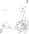
Fig.1 shows an axonometric view of a vehicle in a first embodiment, in conditions of use; -
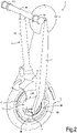
Fig.2 shows an axonometric view of the vehicle in folded condition; -
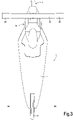
Fig.3 shows a plan view of the vehicle in a position with the steering not turned; -
Fig.4 shows a view analogous toFig.3 , with the front wheel turned to the left; -
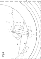
Fig.5 shows an axonometric view of the front part of the vehicle with the handlebar detached from the front wheel; -
Fig.6 shows a section according to a vertical plane of the double hinge that connects the front wheel to the footboard; -
Fig.7 shows a lateral view with parts removed of the front portion of the vehicle; -
Fig.8 shows a lateral view of the front wheel of the vehicle without the tyre; -
Fig.9 shows a section according to IX-IX ofFig.8 ; -
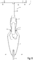
Fig.10 shows an axonometric view of a vehicle in a second embodiment; -
Fig.11 shows a plan view of the vehicle ofFig.10 ; and -
Figs. 12 and13 show an enlarged axonometric view of the constraint between front wheel and footboard of the vehicle ofFigs. 10 and11 . - An embodiment of the vehicle disclosed herein is shown in
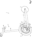
Figs. 1 to 9 . - The
vehicle 1 comprises a front steeredwheel 3 and arear wheel 5. The front steeredwheel 3 is connected to therear wheel 5 through afootboard 7. Therear wheel 5 is connected to thefootboard 7 so as to rotate with respect thereto about theaxis 5A (Figs.3 ,4 ) of therear wheel 5. - A
handlebar 9, with ahorizontal bar 9A and an upright 9B, is rigidly connected to the front steeredwheel 3, in the manner described in greater detail below. Thehorizontal bar 9A forms handles orhandgrips 9C that are gripped firmly by the rider to control the vehicle and in particular to steer the vehicle and to control the acceleration, deceleration and braking thereof. - In the embodiment illustrated, as better shown in
Fig.7 , the front steeredwheel 3 comprises an innerannular hub 3A and anouter rim 3B. Theannular hub 3A and therim 3B are concentric and therim 3B is rotatingly supported about theannular hub 3A by means of a bearing system 4 (seeFigs. 8 and 9 ). Annularprotective covers 6 can be associated with therim 3B to protect thebearings 4. - According to some embodiments, as shown in particular in
Figs. 8 and 9 , which show thefront wheel 3 with the tyre removed and with the groove for housing the tyre indicated with 3S, thewindings 8 of anelectric motor 10 are integral with theannular hub 3A and coact withpermanent magnets 16 integral with therim 3B. In substance, theelectric windings 8 integral with theannular hub 3A form the stator of theelectric motor 10 and thepermanent magnets 16 integral with therim 3B form the rotor of theelectric motor 10. - The
annular hub 3 is configured so that thehandlebar 9 and thefootboard 7 are constrained thereto. More in particular, thehandlebar 9 is rigidly constrained to theannular hub 3A through aconnection member 11. In the illustrated embodiment, theconnection member 11 is fork-shaped and has a pair ofarms 11A connected to across member 11B, with which the lower end of the upright 9B of thehandlebar 9 is integral. The shape of theconnection member 11 is shown in particular inFig.5 . Theconnection member 11 is fixed to theannular hub 3A along the upper part thereof, i.e., in a position above the rotation axis A-A of the front steeredwheel 3. The rigid connection between theconnection member 11 and theannular hub 3A can be (seeFig.5 ) through pins that are inserted into holes 11F of theconnection member 11 and into correspondingholes 3F provided in a crescent-shapedplate 3D of theannular hub 3A, which extends into the empty central space of theannular hub 3A, or to theannular hub 3 directly. - A
battery 12, suitably protected in a housing, can be fixed to the lower ends of thearms 11A of theconnection member 11. Thebattery 12 extends from one to the other of thearms 11A, so as to occupy part of the empty volume inside theannular hub 3A of the front steeredwheel 3. Contrary to conventional electric scooters, in the vehicle according to the present invention the battery, which is a relatively heavy component of the vehicle, does not add weight to the footboard, but its weight is substantially supported by the front steeredwheel 3, thus contributing to make riding of the vehicle easier and above all to make the vehicle easier and less cumbersome to transport when folded (Fig.2 ). In fact, in this condition the weight of the battery, together with the weight of the other components (handlebar 9,footboard 7, rear wheel 5) is transferred to the ground through the front steeredwheel 3 and the user can easily push thevehicle 1 by hand, steering it with thehandlebar 9. If the motor is switched on, the electronic acceleration and deceleration controls managed by thehandlebar 9 allow thevehicle 1 to be moved forward, even when it is folded, by means of thehandlebar 9. - To connect the
footboard 7 to the front steered wheel 3 adouble hinge 13, shown in particular inFigs. 5 and6 , is provided. Thedouble hinge 13 defines a first substantially horizontal axis B-B (when the vehicle is moving forward in a straight line, seeFig.3 ). The axis B-B is the axis about which thefootboard 7 rotates to take the vehicle from the riding condition (Fig.1 ) to the folded position (Fig.2 ). The axis B-B can be defined by a pair ofpins 13A. Thehinge 13 further defines a second rotation axis C-C orthogonal to the first rotation axis B-B and lying on a vertical plane (when the vehicle is in the position for forward movement in a straight line, not inclined laterally, seeFig.3 ) oriented according to the front-rear direction of thevehicle 1, i.e., according to the direction of forward movement. As can be seen inFig.6 , the axis C-C is preferably inclined with respect to the vertical to obtain a non-zero front wheel trail angle. The rotation axis C-C is defined by apin 13B of thehinge 13 and forms the steering axis of the front steeredwheel 3. Thepin 13B is hinged in a crescent-shapedplate 3E of theannular hub 3A. The twoplates plate 3D is above the rotation axis A-A of the front steeredwheel 3, theplate 3E is under the rotation axis A-A. - With the described arrangement, the front steered
wheel 3, which is also the drive wheel of thevehicle 1, can rotate freely about the steering axis C-C under the control of thehandlebar 9, while the rider is on the vehicle, standing on thefootboard 7. When the vehicle requires to be folded, thefootboard 7 is lifted and positioned approximately parallel to thehandlebar 9 by means of a rotation about the horizontal axis B-B, without the need to release members. - The electronic control of the vehicle, which can be made similarly to those used in monowheel vehicles or in "Segway"® vehicles, can be housed in the
connection member 11. This electronic control, derived from solutions available on the market, controls the power supply of the electric motor, and in particular acceleration and deceleration, and other operations such as battery charging. - The described vehicle allows to obtained a plurality of advantages over individual electric vehicles of the current art, briefly referred to in the introduction. The dimension of the front wheel and its use as steered and drive wheel makes riding simpler and more comfortable, as well as safer, even on rough ground. The acceleration and braking torques generated by the motor are high and provide greater safety while riding.
- In the embodiment described above, the
double hinge 13, with which thefootboard 7 is constrained to thefront wheel 3 to allow rotation of the wheel about the steering axis C-C and rotation of thefootboard 7 about the axis B-B, is embodied by twopins -
Figs. 10 to 13 show a second embodiment of thevehicle 1, which differs from the vehicle ofFigs. 1 to 9 mainly due to the different structure of the double hinge connection between thefootboard 7 and thefront wheel 3. InFigs. 10 to 13 the same numbers indicate identical or equivalent parts to those ofFigs. 1 to 9 , which will not be described again. - The different structure of the double hinge connection between the
footboard 7 and thefront wheel 3 is shown in particular in the enlarged details ofFigs. 12 and13 . InFig. 12 thefront wheel 3 is in a straight position, i.e., thefront wheel 3 lies in the vertical plane oriented in a front-rear direction of the vehicle, i.e., oriented in the direction of movement of the vehicle. InFig. 13 thefront wheel 3 is turned to the right. - In this embodiment, the
pin 13A that defines the rotation axis B-B is rigidly connected to theplate 3D, integral with theannular hub 3A. Thefootboard 7 is integral with twoopposite guides 14, into which the two opposite ends of thepin 13A are inserted. The guides can advantageously be in the shape of arcs of a circle sufficiently large to allow thepin 13A to be guided for the whole of the arc of rotation of thefront wheel 3 about the steering axis C-C. This axis is defined by theguides 14, which impart a rotation movement to thepin 13A about the axis C-C when the rider imparts a steered movement to thefront wheel 3 by means of thehandlebar 9. The tipping movement of thefootboard 7 toward thehandlebar 9 when thevehicle 1 is folded is obtained by rotation of the guides 14 (integral with the footboard 7) about the axis B-B of thepin 13A. As can be understood fromFigs. 12 and13 , thedouble hinge 13 is in this case defined by two prismatic pairs, formed by theguides 14 in which thepin 13 runs. - The small dimension of the rear wheel does not affect riding safety, as the stability of the vehicle is given by the
front wheel 3. This allows the use of arear wheel 5 of small diameter without loss of safety and riding comfort, reducing the weight and footprint of the vehicle. The possibility of folding thefootboard 7 and therear wheel 5 toward thehandlebar 9 allows the dimensions of the vehicle to be reduced thus making it easier to transport, for example on public transport (trains, buses). The possibility of handling thevehicle 1 in the folded arrangement (Fig.2 ) using thehandlebar 9 maintaining the drive motor of thevehicle 1 running reduces the effort required to push the vehicle by hand. - The vehicle described herein is ridden in substance like an electric monowheel, but with much greater ease, as it does not require balance skills due to the presence of a handlebar, which also acts as member for controlling accelerations and decelerations of the vehicle, and as support for the rider. The footboard provides a convenient footrest and the rear wheel, in combination with the front wheel and the footboard, allow the rider to maintain balance easily and intuitively.
Claims (11)
- An electric vehicle (1) comprising:- a front steered wheel (3);- a rear wheel (5);- a footboard (7) connecting the front steered wheel (3) and the rear wheel (5);- an electric traction motor (10) incorporated in the front wheel (3);- a power supply battery (12); and- a handlebar (9) constrained to the front wheel (3), configured to impart steered movements to the front wheel;wherein:- the front wheel (3) comprises: an annular hub (3A), with which a stator of the electric motor is integral, and a rim (3B), supported rotating about the annular hub (3A) and with which a rotor of the electric motor is integral;- the footboard is hinged by means of a double hinge (13) to the annular hub (3A) of the front wheel (3); the double hinge (13) allowing a folding movement of the footboard (7) about a first hinge axis (B-B) toward the handlebar (9), and a steered movement of the front wheel (3) about a second hinge axis (C-C), orthogonal to the first hinge axis (B-B); and- the handlebar (9) is adapted to impart acceleration and deceleration commands to the electric motor (10) through forward and backward movements of the handlebar (9) in the direction of forward movement of the vehicle, by means of an electronic control.
- The vehicle (1) of claim 1, wherein the handlebar (9) is rigidly constrained to the annular hub (3A) of the front wheel (3).
- The vehicle (1) of claim 1 or 2, wherein the handlebar (9) is constrained to the annular hub (3A) of the front wheel (3) in a position above the rotation axis of the front wheel.
- The vehicle (1) of claim 1, 2 or 3, wherein the double hinge (13) is positioned under the rotation axis of the front wheel (3).
- The vehicle (1) of one or more of the preceding claims, wherein the electronic control uses a gyroscope.
- The vehicle (1) of one or more of the preceding claims, wherein the front wheel (3) has a larger dimension than the rear wheel (5), with a radius preferably between around 1.5 and around 2 times the radius of the rear wheel (5).
- The vehicle (1) of one or more of the preceding claims, wherein the handlebar (9) is connected to the front wheel (3) through a connection member (11), rigidly connected to the handlebar (9) and to the annular hub (3A) of the front wheel (3); and wherein the double hinge (13) is configured to allow folding of the footboard (7) about a first hinge axis (B-B) toward the handlebar (9), which remains rigidly connected, through the connection member (11) to the annular hub (3A) of the front wheel (3).
- The vehicle (1) of claim 7, wherein the connection member (11) is a fork member which partially surrounds the front wheel (3) and has two opposite arms (11A) rigidly constrained to the annular hub (3A) of the front wheel (3).
- The vehicle (1) of one or more of the preceding claims, wherein the battery (12) is rigidly constrained to the handlebar (9).
- The vehicle (1) of claim 8, wherein the battery (12) is rigidly constrained to the two arms (11A) of the fork connection member (11), which connects the handlebar (9) to the front wheel (3), and extends through the annular hub (3A) of the front wheel (3).
- The vehicle (1) of one or more of the preceding claims, wherein the double hinge (13) comprises a first pin (13A) defining the rotation axis (B-B) of the footboard (7) about the annular hub (3A) of the front wheel (3), and a second pin (13B) defining a steering axis (C-C), the second pin (13B) preferably being integral with the annular hub (3A) and the first pin (13A) being hinged to the second pin (13B) to rotate about the steering axis (C-C).
Applications Claiming Priority (1)
| Application Number | Priority Date | Filing Date | Title |
|---|---|---|---|
| IT202000028175 | 2020-11-24 |
Publications (3)
| Publication Number | Publication Date |
|---|---|
| EP4001079A1 true EP4001079A1 (en) | 2022-05-25 |
| EP4001079C0 EP4001079C0 (en) | 2023-08-09 |
| EP4001079B1 EP4001079B1 (en) | 2023-08-09 |
Family
ID=74557136
Family Applications (1)
| Application Number | Title | Priority Date | Filing Date |
|---|---|---|---|
| EP21209478.3A Active EP4001079B1 (en) | 2020-11-24 | 2021-11-22 | Two wheeled electric vehicle |
Country Status (1)
| Country | Link |
|---|---|
| EP (1) | EP4001079B1 (en) |
Cited By (1)
| Publication number | Priority date | Publication date | Assignee | Title |
|---|---|---|---|---|
| GB2608060B (en) * | 2020-02-13 | 2024-03-27 | James White Robert | Motorcycle and powertrain |
Citations (5)
| Publication number | Priority date | Publication date | Assignee | Title |
|---|---|---|---|---|
| US6302230B1 (en) | 1999-06-04 | 2001-10-16 | Deka Products Limited Partnership | Personal mobility vehicles and methods |
| DE10045821A1 (en) * | 2000-09-15 | 2002-03-28 | Harald Kutzke | Folding scooter has tread-plate, links, rocker arms as mountings for front and rear wheels, steering-head or tube, and handles. |
| EP2425989A1 (en) | 2010-09-01 | 2012-03-07 | Dijiya Energy Saving Technology Inc. | Integrated wheel and electric scooter using the wheel |
| US8830048B2 (en) | 1999-06-04 | 2014-09-09 | Deka Products Limited Partnership | Control of a personal transporter based on user position |
| WO2016027018A1 (en) | 2014-08-22 | 2016-02-25 | Peugeot Citroen Automobiles Sa | Scooter-type vehicle with caster wheels |
-
2021
- 2021-11-22 EP EP21209478.3A patent/EP4001079B1/en active Active
Patent Citations (6)
| Publication number | Priority date | Publication date | Assignee | Title |
|---|---|---|---|---|
| US6302230B1 (en) | 1999-06-04 | 2001-10-16 | Deka Products Limited Partnership | Personal mobility vehicles and methods |
| US8830048B2 (en) | 1999-06-04 | 2014-09-09 | Deka Products Limited Partnership | Control of a personal transporter based on user position |
| DE10045821A1 (en) * | 2000-09-15 | 2002-03-28 | Harald Kutzke | Folding scooter has tread-plate, links, rocker arms as mountings for front and rear wheels, steering-head or tube, and handles. |
| EP2425989A1 (en) | 2010-09-01 | 2012-03-07 | Dijiya Energy Saving Technology Inc. | Integrated wheel and electric scooter using the wheel |
| WO2016027018A1 (en) | 2014-08-22 | 2016-02-25 | Peugeot Citroen Automobiles Sa | Scooter-type vehicle with caster wheels |
| EP3183165A1 (en) | 2014-08-22 | 2017-06-28 | Peugeot Citroën Automobiles S.A. | Scooter-type vehicle with caster wheels |
Cited By (1)
| Publication number | Priority date | Publication date | Assignee | Title |
|---|---|---|---|---|
| GB2608060B (en) * | 2020-02-13 | 2024-03-27 | James White Robert | Motorcycle and powertrain |
Also Published As
| Publication number | Publication date |
|---|---|
| EP4001079C0 (en) | 2023-08-09 |
| EP4001079B1 (en) | 2023-08-09 |
Similar Documents
| Publication | Publication Date | Title |
|---|---|---|
| US20200062328A1 (en) | Powered personal mobility vehicle with rotating wheels | |
| US9085334B2 (en) | Electric-powered self-balancing unicycle | |
| JP5462873B2 (en) | bicycle | |
| JP4478963B1 (en) | bicycle | |
| JP2011527972A5 (en) | ||
| JP2001506947A (en) | Single-rail motorcycle | |
| US11345438B2 (en) | Vehicle with a power unit | |
| EP4001079B1 (en) | Two wheeled electric vehicle | |
| US20220161885A1 (en) | A cargo-carrying wheeled vehicle | |
| US9493200B2 (en) | Couplable drive unit and steering unit | |
| CN201272455Y (en) | Portable electric scooter | |
| JP2001030972A (en) | One-axle wheel vehicle | |
| US20230257055A1 (en) | Three-Wheeled Vehicle With Multipart Frame | |
| US10759486B2 (en) | Three or four wheeled human powered vehicle with dual wheel front steering and single or dual wheel rear drive | |
| JP7122683B2 (en) | electric tricycle | |
| CN112789216A (en) | Week wheel barrow | |
| CN213473411U (en) | Foldable bicycle | |
| CN206528569U (en) | A kind of scooter | |
| CN206813189U (en) | Three-wheel electric scooter | |
| CN205801340U (en) | A kind of scooter | |
| CN213354722U (en) | Folding scooter | |
| JP2005119450A (en) | Front double-wheel and rear single-wheel tricycle | |
| CN216508818U (en) | Multifunctional electric scooter | |
| US20230391416A1 (en) | Vehicle | |
| CN112078708A (en) | AI monocycle |
Legal Events
| Date | Code | Title | Description |
|---|---|---|---|
| PUAI | Public reference made under article 153(3) epc to a published international application that has entered the european phase |
Free format text: ORIGINAL CODE: 0009012 |
|
| STAA | Information on the status of an ep patent application or granted ep patent |
Free format text: STATUS: THE APPLICATION HAS BEEN PUBLISHED |
|
| AK | Designated contracting states |
Kind code of ref document: A1 Designated state(s): AL AT BE BG CH CY CZ DE DK EE ES FI FR GB GR HR HU IE IS IT LI LT LU LV MC MK MT NL NO PL PT RO RS SE SI SK SM TR |
|
| STAA | Information on the status of an ep patent application or granted ep patent |
Free format text: STATUS: REQUEST FOR EXAMINATION WAS MADE |
|
| 17P | Request for examination filed |
Effective date: 20220909 |
|
| RBV | Designated contracting states (corrected) |
Designated state(s): AL AT BE BG CH CY CZ DE DK EE ES FI FR GB GR HR HU IE IS IT LI LT LU LV MC MK MT NL NO PL PT RO RS SE SI SK SM TR |
|
| RIC1 | Information provided on ipc code assigned before grant |
Ipc: B62K 23/02 20060101ALI20221214BHEP Ipc: B62K 21/00 20060101AFI20221214BHEP |
|
| GRAP | Despatch of communication of intention to grant a patent |
Free format text: ORIGINAL CODE: EPIDOSNIGR1 |
|
| STAA | Information on the status of an ep patent application or granted ep patent |
Free format text: STATUS: GRANT OF PATENT IS INTENDED |
|
| RIC1 | Information provided on ipc code assigned before grant |
Ipc: B62K 23/02 20060101ALI20230123BHEP Ipc: B62K 21/00 20060101ALI20230123BHEP Ipc: B62K 15/00 20060101ALI20230123BHEP Ipc: B62K 3/00 20060101AFI20230123BHEP |
|
| INTG | Intention to grant announced |
Effective date: 20230301 |
|
| GRAS | Grant fee paid |
Free format text: ORIGINAL CODE: EPIDOSNIGR3 |
|
| GRAA | (expected) grant |
Free format text: ORIGINAL CODE: 0009210 |
|
| STAA | Information on the status of an ep patent application or granted ep patent |
Free format text: STATUS: THE PATENT HAS BEEN GRANTED |
|
| AK | Designated contracting states |
Kind code of ref document: B1 Designated state(s): AL AT BE BG CH CY CZ DE DK EE ES FI FR GB GR HR HU IE IS IT LI LT LU LV MC MK MT NL NO PL PT RO RS SE SI SK SM TR |
|
| REG | Reference to a national code |
Ref country code: GB Ref legal event code: FG4D |
|
| REG | Reference to a national code |
Ref country code: CH Ref legal event code: EP |
|
| REG | Reference to a national code |
Ref country code: IE Ref legal event code: FG4D |
|
| REG | Reference to a national code |
Ref country code: DE Ref legal event code: R096 Ref document number: 602021004150 Country of ref document: DE |
|
| U01 | Request for unitary effect filed |
Effective date: 20230904 |
|
| U07 | Unitary effect registered |
Designated state(s): AT BE BG DE DK EE FI FR IT LT LU LV MT NL PT SE SI Effective date: 20230914 |
|
| U20 | Renewal fee paid [unitary effect] |
Year of fee payment: 3 Effective date: 20231127 |
|
| PG25 | Lapsed in a contracting state [announced via postgrant information from national office to epo] |
Ref country code: GR Free format text: LAPSE BECAUSE OF FAILURE TO SUBMIT A TRANSLATION OF THE DESCRIPTION OR TO PAY THE FEE WITHIN THE PRESCRIBED TIME-LIMIT Effective date: 20231110 |
|
| PG25 | Lapsed in a contracting state [announced via postgrant information from national office to epo] |
Ref country code: IS Free format text: LAPSE BECAUSE OF FAILURE TO SUBMIT A TRANSLATION OF THE DESCRIPTION OR TO PAY THE FEE WITHIN THE PRESCRIBED TIME-LIMIT Effective date: 20231209 |
|
| PG25 | Lapsed in a contracting state [announced via postgrant information from national office to epo] |
Ref country code: RS Free format text: LAPSE BECAUSE OF FAILURE TO SUBMIT A TRANSLATION OF THE DESCRIPTION OR TO PAY THE FEE WITHIN THE PRESCRIBED TIME-LIMIT Effective date: 20230809 Ref country code: NO Free format text: LAPSE BECAUSE OF FAILURE TO SUBMIT A TRANSLATION OF THE DESCRIPTION OR TO PAY THE FEE WITHIN THE PRESCRIBED TIME-LIMIT Effective date: 20231109 Ref country code: IS Free format text: LAPSE BECAUSE OF FAILURE TO SUBMIT A TRANSLATION OF THE DESCRIPTION OR TO PAY THE FEE WITHIN THE PRESCRIBED TIME-LIMIT Effective date: 20231209 Ref country code: HR Free format text: LAPSE BECAUSE OF FAILURE TO SUBMIT A TRANSLATION OF THE DESCRIPTION OR TO PAY THE FEE WITHIN THE PRESCRIBED TIME-LIMIT Effective date: 20230809 Ref country code: GR Free format text: LAPSE BECAUSE OF FAILURE TO SUBMIT A TRANSLATION OF THE DESCRIPTION OR TO PAY THE FEE WITHIN THE PRESCRIBED TIME-LIMIT Effective date: 20231110 |
|
| PG25 | Lapsed in a contracting state [announced via postgrant information from national office to epo] |
Ref country code: PL Free format text: LAPSE BECAUSE OF FAILURE TO SUBMIT A TRANSLATION OF THE DESCRIPTION OR TO PAY THE FEE WITHIN THE PRESCRIBED TIME-LIMIT Effective date: 20230809 |