EP4001029A1 - Fahrzeugbewegungsmanagementsystem und aktuatorsteuerungssystem für ein fahrzeug - Google Patents
Fahrzeugbewegungsmanagementsystem und aktuatorsteuerungssystem für ein fahrzeug Download PDFInfo
- Publication number
- EP4001029A1 EP4001029A1 EP20207778.0A EP20207778A EP4001029A1 EP 4001029 A1 EP4001029 A1 EP 4001029A1 EP 20207778 A EP20207778 A EP 20207778A EP 4001029 A1 EP4001029 A1 EP 4001029A1
- Authority
- EP
- European Patent Office
- Prior art keywords
- wheel
- vehicle
- actuator
- control system
- torque
- Prior art date
- Legal status (The legal status is an assumption and is not a legal conclusion. Google has not performed a legal analysis and makes no representation as to the accuracy of the status listed.)
- Pending
Links
- 238000013507 mapping Methods 0.000 claims description 74
- 238000000034 method Methods 0.000 claims description 9
- 238000004891 communication Methods 0.000 claims description 5
- 238000004590 computer program Methods 0.000 claims description 4
- 230000005540 biological transmission Effects 0.000 description 10
- 239000010410 layer Substances 0.000 description 10
- 230000001133 acceleration Effects 0.000 description 8
- 230000008901 benefit Effects 0.000 description 5
- 230000000694 effects Effects 0.000 description 3
- 210000003462 vein Anatomy 0.000 description 2
- 239000010426 asphalt Substances 0.000 description 1
- 230000008859 change Effects 0.000 description 1
- 230000007812 deficiency Effects 0.000 description 1
- 238000011161 development Methods 0.000 description 1
- 238000004146 energy storage Methods 0.000 description 1
- 230000003993 interaction Effects 0.000 description 1
- 239000002346 layers by function Substances 0.000 description 1
- 238000005259 measurement Methods 0.000 description 1
- 238000012986 modification Methods 0.000 description 1
- 230000004048 modification Effects 0.000 description 1
- 238000012544 monitoring process Methods 0.000 description 1
- 238000012545 processing Methods 0.000 description 1
- 230000001172 regenerating effect Effects 0.000 description 1
- 230000004044 response Effects 0.000 description 1
- 238000005096 rolling process Methods 0.000 description 1
- 239000000725 suspension Substances 0.000 description 1
Images


Classifications
-
- B—PERFORMING OPERATIONS; TRANSPORTING
- B60—VEHICLES IN GENERAL
- B60L—PROPULSION OF ELECTRICALLY-PROPELLED VEHICLES; SUPPLYING ELECTRIC POWER FOR AUXILIARY EQUIPMENT OF ELECTRICALLY-PROPELLED VEHICLES; ELECTRODYNAMIC BRAKE SYSTEMS FOR VEHICLES IN GENERAL; MAGNETIC SUSPENSION OR LEVITATION FOR VEHICLES; MONITORING OPERATING VARIABLES OF ELECTRICALLY-PROPELLED VEHICLES; ELECTRIC SAFETY DEVICES FOR ELECTRICALLY-PROPELLED VEHICLES
- B60L15/00—Methods, circuits, or devices for controlling the traction-motor speed of electrically-propelled vehicles
- B60L15/20—Methods, circuits, or devices for controlling the traction-motor speed of electrically-propelled vehicles for control of the vehicle or its driving motor to achieve a desired performance, e.g. speed, torque, programmed variation of speed
-
- B—PERFORMING OPERATIONS; TRANSPORTING
- B60—VEHICLES IN GENERAL
- B60T—VEHICLE BRAKE CONTROL SYSTEMS OR PARTS THEREOF; BRAKE CONTROL SYSTEMS OR PARTS THEREOF, IN GENERAL; ARRANGEMENT OF BRAKING ELEMENTS ON VEHICLES IN GENERAL; PORTABLE DEVICES FOR PREVENTING UNWANTED MOVEMENT OF VEHICLES; VEHICLE MODIFICATIONS TO FACILITATE COOLING OF BRAKES
- B60T8/00—Arrangements for adjusting wheel-braking force to meet varying vehicular or ground-surface conditions, e.g. limiting or varying distribution of braking force
- B60T8/17—Using electrical or electronic regulation means to control braking
- B60T8/1701—Braking or traction control means specially adapted for particular types of vehicles
- B60T8/1708—Braking or traction control means specially adapted for particular types of vehicles for lorries or tractor-trailer combinations
-
- B—PERFORMING OPERATIONS; TRANSPORTING
- B60—VEHICLES IN GENERAL
- B60W—CONJOINT CONTROL OF VEHICLE SUB-UNITS OF DIFFERENT TYPE OR DIFFERENT FUNCTION; CONTROL SYSTEMS SPECIALLY ADAPTED FOR HYBRID VEHICLES; ROAD VEHICLE DRIVE CONTROL SYSTEMS FOR PURPOSES NOT RELATED TO THE CONTROL OF A PARTICULAR SUB-UNIT
- B60W30/00—Purposes of road vehicle drive control systems not related to the control of a particular sub-unit, e.g. of systems using conjoint control of vehicle sub-units
- B60W30/18—Propelling the vehicle
- B60W30/18172—Preventing, or responsive to skidding of wheels
-
- B—PERFORMING OPERATIONS; TRANSPORTING
- B60—VEHICLES IN GENERAL
- B60T—VEHICLE BRAKE CONTROL SYSTEMS OR PARTS THEREOF; BRAKE CONTROL SYSTEMS OR PARTS THEREOF, IN GENERAL; ARRANGEMENT OF BRAKING ELEMENTS ON VEHICLES IN GENERAL; PORTABLE DEVICES FOR PREVENTING UNWANTED MOVEMENT OF VEHICLES; VEHICLE MODIFICATIONS TO FACILITATE COOLING OF BRAKES
- B60T8/00—Arrangements for adjusting wheel-braking force to meet varying vehicular or ground-surface conditions, e.g. limiting or varying distribution of braking force
- B60T8/17—Using electrical or electronic regulation means to control braking
- B60T8/172—Determining control parameters used in the regulation, e.g. by calculations involving measured or detected parameters
-
- B—PERFORMING OPERATIONS; TRANSPORTING
- B60—VEHICLES IN GENERAL
- B60T—VEHICLE BRAKE CONTROL SYSTEMS OR PARTS THEREOF; BRAKE CONTROL SYSTEMS OR PARTS THEREOF, IN GENERAL; ARRANGEMENT OF BRAKING ELEMENTS ON VEHICLES IN GENERAL; PORTABLE DEVICES FOR PREVENTING UNWANTED MOVEMENT OF VEHICLES; VEHICLE MODIFICATIONS TO FACILITATE COOLING OF BRAKES
- B60T8/00—Arrangements for adjusting wheel-braking force to meet varying vehicular or ground-surface conditions, e.g. limiting or varying distribution of braking force
- B60T8/17—Using electrical or electronic regulation means to control braking
- B60T8/176—Brake regulation specially adapted to prevent excessive wheel slip during vehicle deceleration, e.g. ABS
- B60T8/1761—Brake regulation specially adapted to prevent excessive wheel slip during vehicle deceleration, e.g. ABS responsive to wheel or brake dynamics, e.g. wheel slip, wheel acceleration or rate of change of brake fluid pressure
- B60T8/17616—Microprocessor-based systems
-
- B—PERFORMING OPERATIONS; TRANSPORTING
- B60—VEHICLES IN GENERAL
- B60W—CONJOINT CONTROL OF VEHICLE SUB-UNITS OF DIFFERENT TYPE OR DIFFERENT FUNCTION; CONTROL SYSTEMS SPECIALLY ADAPTED FOR HYBRID VEHICLES; ROAD VEHICLE DRIVE CONTROL SYSTEMS FOR PURPOSES NOT RELATED TO THE CONTROL OF A PARTICULAR SUB-UNIT
- B60W10/00—Conjoint control of vehicle sub-units of different type or different function
- B60W10/04—Conjoint control of vehicle sub-units of different type or different function including control of propulsion units
- B60W10/08—Conjoint control of vehicle sub-units of different type or different function including control of propulsion units including control of electric propulsion units, e.g. motors or generators
-
- B—PERFORMING OPERATIONS; TRANSPORTING
- B60—VEHICLES IN GENERAL
- B60W—CONJOINT CONTROL OF VEHICLE SUB-UNITS OF DIFFERENT TYPE OR DIFFERENT FUNCTION; CONTROL SYSTEMS SPECIALLY ADAPTED FOR HYBRID VEHICLES; ROAD VEHICLE DRIVE CONTROL SYSTEMS FOR PURPOSES NOT RELATED TO THE CONTROL OF A PARTICULAR SUB-UNIT
- B60W10/00—Conjoint control of vehicle sub-units of different type or different function
- B60W10/18—Conjoint control of vehicle sub-units of different type or different function including control of braking systems
- B60W10/184—Conjoint control of vehicle sub-units of different type or different function including control of braking systems with wheel brakes
-
- B—PERFORMING OPERATIONS; TRANSPORTING
- B60—VEHICLES IN GENERAL
- B60W—CONJOINT CONTROL OF VEHICLE SUB-UNITS OF DIFFERENT TYPE OR DIFFERENT FUNCTION; CONTROL SYSTEMS SPECIALLY ADAPTED FOR HYBRID VEHICLES; ROAD VEHICLE DRIVE CONTROL SYSTEMS FOR PURPOSES NOT RELATED TO THE CONTROL OF A PARTICULAR SUB-UNIT
- B60W50/00—Details of control systems for road vehicle drive control not related to the control of a particular sub-unit, e.g. process diagnostic or vehicle driver interfaces
-
- B—PERFORMING OPERATIONS; TRANSPORTING
- B60—VEHICLES IN GENERAL
- B60L—PROPULSION OF ELECTRICALLY-PROPELLED VEHICLES; SUPPLYING ELECTRIC POWER FOR AUXILIARY EQUIPMENT OF ELECTRICALLY-PROPELLED VEHICLES; ELECTRODYNAMIC BRAKE SYSTEMS FOR VEHICLES IN GENERAL; MAGNETIC SUSPENSION OR LEVITATION FOR VEHICLES; MONITORING OPERATING VARIABLES OF ELECTRICALLY-PROPELLED VEHICLES; ELECTRIC SAFETY DEVICES FOR ELECTRICALLY-PROPELLED VEHICLES
- B60L2240/00—Control parameters of input or output; Target parameters
- B60L2240/40—Drive Train control parameters
- B60L2240/46—Drive Train control parameters related to wheels
- B60L2240/461—Speed
-
- B—PERFORMING OPERATIONS; TRANSPORTING
- B60—VEHICLES IN GENERAL
- B60L—PROPULSION OF ELECTRICALLY-PROPELLED VEHICLES; SUPPLYING ELECTRIC POWER FOR AUXILIARY EQUIPMENT OF ELECTRICALLY-PROPELLED VEHICLES; ELECTRODYNAMIC BRAKE SYSTEMS FOR VEHICLES IN GENERAL; MAGNETIC SUSPENSION OR LEVITATION FOR VEHICLES; MONITORING OPERATING VARIABLES OF ELECTRICALLY-PROPELLED VEHICLES; ELECTRIC SAFETY DEVICES FOR ELECTRICALLY-PROPELLED VEHICLES
- B60L2240/00—Control parameters of input or output; Target parameters
- B60L2240/40—Drive Train control parameters
- B60L2240/46—Drive Train control parameters related to wheels
- B60L2240/463—Torque
-
- B—PERFORMING OPERATIONS; TRANSPORTING
- B60—VEHICLES IN GENERAL
- B60L—PROPULSION OF ELECTRICALLY-PROPELLED VEHICLES; SUPPLYING ELECTRIC POWER FOR AUXILIARY EQUIPMENT OF ELECTRICALLY-PROPELLED VEHICLES; ELECTRODYNAMIC BRAKE SYSTEMS FOR VEHICLES IN GENERAL; MAGNETIC SUSPENSION OR LEVITATION FOR VEHICLES; MONITORING OPERATING VARIABLES OF ELECTRICALLY-PROPELLED VEHICLES; ELECTRIC SAFETY DEVICES FOR ELECTRICALLY-PROPELLED VEHICLES
- B60L2240/00—Control parameters of input or output; Target parameters
- B60L2240/40—Drive Train control parameters
- B60L2240/46—Drive Train control parameters related to wheels
- B60L2240/465—Slip
-
- B—PERFORMING OPERATIONS; TRANSPORTING
- B60—VEHICLES IN GENERAL
- B60L—PROPULSION OF ELECTRICALLY-PROPELLED VEHICLES; SUPPLYING ELECTRIC POWER FOR AUXILIARY EQUIPMENT OF ELECTRICALLY-PROPELLED VEHICLES; ELECTRODYNAMIC BRAKE SYSTEMS FOR VEHICLES IN GENERAL; MAGNETIC SUSPENSION OR LEVITATION FOR VEHICLES; MONITORING OPERATING VARIABLES OF ELECTRICALLY-PROPELLED VEHICLES; ELECTRIC SAFETY DEVICES FOR ELECTRICALLY-PROPELLED VEHICLES
- B60L2260/00—Operating Modes
- B60L2260/20—Drive modes; Transition between modes
- B60L2260/28—Four wheel or all wheel drive
-
- B—PERFORMING OPERATIONS; TRANSPORTING
- B60—VEHICLES IN GENERAL
- B60T—VEHICLE BRAKE CONTROL SYSTEMS OR PARTS THEREOF; BRAKE CONTROL SYSTEMS OR PARTS THEREOF, IN GENERAL; ARRANGEMENT OF BRAKING ELEMENTS ON VEHICLES IN GENERAL; PORTABLE DEVICES FOR PREVENTING UNWANTED MOVEMENT OF VEHICLES; VEHICLE MODIFICATIONS TO FACILITATE COOLING OF BRAKES
- B60T2270/00—Further aspects of brake control systems not otherwise provided for
- B60T2270/86—Optimizing braking by using ESP vehicle or tire model
-
- B—PERFORMING OPERATIONS; TRANSPORTING
- B60—VEHICLES IN GENERAL
- B60W—CONJOINT CONTROL OF VEHICLE SUB-UNITS OF DIFFERENT TYPE OR DIFFERENT FUNCTION; CONTROL SYSTEMS SPECIALLY ADAPTED FOR HYBRID VEHICLES; ROAD VEHICLE DRIVE CONTROL SYSTEMS FOR PURPOSES NOT RELATED TO THE CONTROL OF A PARTICULAR SUB-UNIT
- B60W50/00—Details of control systems for road vehicle drive control not related to the control of a particular sub-unit, e.g. process diagnostic or vehicle driver interfaces
- B60W2050/0001—Details of the control system
- B60W2050/0019—Control system elements or transfer functions
-
- B—PERFORMING OPERATIONS; TRANSPORTING
- B60—VEHICLES IN GENERAL
- B60W—CONJOINT CONTROL OF VEHICLE SUB-UNITS OF DIFFERENT TYPE OR DIFFERENT FUNCTION; CONTROL SYSTEMS SPECIALLY ADAPTED FOR HYBRID VEHICLES; ROAD VEHICLE DRIVE CONTROL SYSTEMS FOR PURPOSES NOT RELATED TO THE CONTROL OF A PARTICULAR SUB-UNIT
- B60W2300/00—Indexing codes relating to the type of vehicle
- B60W2300/12—Trucks; Load vehicles
-
- B—PERFORMING OPERATIONS; TRANSPORTING
- B60—VEHICLES IN GENERAL
- B60W—CONJOINT CONTROL OF VEHICLE SUB-UNITS OF DIFFERENT TYPE OR DIFFERENT FUNCTION; CONTROL SYSTEMS SPECIALLY ADAPTED FOR HYBRID VEHICLES; ROAD VEHICLE DRIVE CONTROL SYSTEMS FOR PURPOSES NOT RELATED TO THE CONTROL OF A PARTICULAR SUB-UNIT
- B60W2520/00—Input parameters relating to overall vehicle dynamics
- B60W2520/26—Wheel slip
-
- B—PERFORMING OPERATIONS; TRANSPORTING
- B60—VEHICLES IN GENERAL
- B60Y—INDEXING SCHEME RELATING TO ASPECTS CROSS-CUTTING VEHICLE TECHNOLOGY
- B60Y2400/00—Special features of vehicle units
- B60Y2400/81—Braking systems
Definitions
- the present disclosure relates to a vehicle motion management system and an actuator control system for a vehicle.
- the present disclosure also relates to a method as well as a control signal operable by the vehicle motion management system and the actuator control system.
- the present disclosure is applicable to electrically propelled vehicles. Although the disclosure will mainly be directed to a vehicle in the form of a truck using electric machines for propulsion, it may also be applicable for other types of vehicles.
- control functionalities intend to improve the drivability of the vehicle, the comfort for the driver, and the safety during operation.
- WO 2017/215751 describes a wheel controller comprising a vehicle wheel capability module arranged in communication with a tire model generator.
- the vehicle wheel capability module is arranged to determine a longitudinal wheel force value based on a calculated wheel slip value.
- WO 2017/215751 provides significant advantages in e.g. overall vehicle dynamic control. However, WO 2017/215751 is still in need of further improvements. In particular, there is a desire to be able to revert from the wheel slip control described in WO 2017/215751 to improve the driving operation at e.g. varying road conditions, i.e. driving operations on both slippery roads as well as operation on dry roads with normal to high friction between the wheel and the road surface.
- a vehicle motion management system for a vehicle, the vehicle motion management system being connectable to an actuator control system for communication of control signals therebetween, wherein the vehicle motion management system is configured to obtain a parameter value relating to a desired wheel force of at least one wheel of the vehicle; determine a torque limit for the at least one wheel based on the parameter value relating to the desired wheel force; determine a mapping model based on a relationship between wheel force and wheel speed of the at least one wheel; determine a parameter value relating to a desired wheel speed for the at least one wheel based on the mapping model; and transmit a control signal to the actuator control system, the control signal being arranged to, when executed by the actuator control system, cause the actuator control system to generate an operating torque to be executed subject to the torque limit and the desired wheel speed.
- the vehicle motion management system and the actuator control system are control systems of the vehicle, where each of the control systems is arranged to execute various control functionalities for controlling operation of the vehicle, in particular for controlling wheel operations.
- the vehicle motion management system is preferably configured to receive, and to determine wheel parameters in a higher layer, i.e. the vehicle motion management system determines a desired torque and wheel slip limit, also referred to as tire slip limit, in a more generalized form, whereas the actuator control system is arranged as a lower layer control system configured to convert the parameters received from the vehicle motion management system to appropriate parameters for an actuator.
- the actuator control system takes e.g. current driveline state(s) into account before forwarding an actuator signal to the actuator.
- the current driveline state may, for example, relate to a current vehicle transmission state, such as a gear stage for the vehicle transmission or a transmission clutch actuation state.
- the parameter value relating to a desired wheel force should be construed as both relating to a desired wheel force as well as a desired wheel torque.
- the desired wheel force/torque is thus obtained in the form of a force/torque demand signal.
- the parameter value relating to the desired wheel force can be based on a request from a vehicle operator, i.e. the accelerator pedal or brake pedal position, or be based on a force demand signal from a system autonomously controlling propulsion operation of the vehicle, or from an advanced driver assistance system (ADAS).
- ADAS advanced driver assistance system
- the torque limit could be determined based on the desired wheel force in combination with a margin value.
- the torque limit is set as a value corresponding to the desired torque plus a predetermined safety margin.
- the torque limit could be based on a torque request from the vehicle operator.
- wheel slip is the relative longitudinal motion between the wheel of the vehicle and the ground surface thereof, i.e. the amount of "skidding", i.e., a difference between the wheel speed over ground and the actual wheel speed.
- the wheel slip can be determined as a relationship between the longitudinal speed of the wheel and the rotational speed of the wheel taking the wheel radius into account. Accordingly, wheel slip is a parameter value relating to the wheel speed, and is preferably defined in a wheel based coordinate system.
- the mapping model which according to an example embodiment, is based on a predetermined characteristic value of the at least one wheel, defines a relationship between wheel force and wheel speed.
- the wheel speed can be defined relative to the ground, and normalized, i.e. the wheel slip, or be defined as an absolute rotational velocity.
- a wheel force value for a specific wheel speed value can be obtained.
- the mapping model can be a fixed mapping model, and/or a mapping model comprising estimated characteristics of the relationship between the wheel forces and the wheel speeds.
- the mapping model could be parameterized based on other factors, such as normal load on the tire, type of tire, wear, friction, etc.
- the vehicle By defining and transmitting a control signal indicative of a torque limit, the vehicle can be operated in a torque limit based control mode as well as a speed based control mode depending on the actual road condition.
- the mapping model could thus preferably be defined to correspond to a relatively slippery road condition, i.e. a wet asphalt road or an icy road.
- the actuator By setting such a mapping model, the actuator will be operated in a torque limit control mode when driving on e.g. a dry road, etc., as the applied torque will hit the torque limit.
- the torque limit will not be reached, and the actuator will be operated in a wheel speed control mode.
- the mapping model may be based on a relationship between wheel force and wheel speed for a predetermined wheel characteristic of the at least one wheel.
- the predetermined wheel characteristic could be, for example, wheel normal load, friction between the wheel and the ground surface, the specific type of tire, etc.
- the mapping model could be modified based on various number of parameters.
- the mapping model may be based on a safety parameter indicative of a current operating condition of the vehicle.
- the mapping model could be based on a relatively slippery road condition.
- the safety parameter hereby enables the actuator to be mainly controlled in the torque limit control mode, and operated in the wheel speed control mode only when the road condition is "more slippery" than the safety parameter has taken into consideration.
- the parameter relating to the desired wheel speed may be a desired wheel slip parameter.
- the torque limit may be determined independently from the determined mapping model.
- the mapping model can be based on e.g. a slippery road condition or any other factor described above, and the torque limit can be freely determined based on e.g. a desired driving experience, etc.
- the mapping model may be a first mapping model, the vehicle motion management system being configured to determine a second mapping model, the second mapping model is based on an increased wheel force compared to the first mapping model for respective wheel speeds.
- the torque limit may be a first torque limit
- the vehicle motion management system being configured to determine a second torque limit relating to a desired wheel speed based on the second mapping model, wherein the transmitted control signal is arranged to, when executed by the actuator control system, cause the actuator control system to generate the operating torque to be executed subject to the desired wheel speed and the first and second torque limits.
- a range can be defined where one mapping model represents e.g. a slippery road condition, while the other mapping model represents e.g. a road condition with relatively high friction between the surface of the wheel and the road surface.
- the applied torque will thus not exceed an upper torque limit and not fall below a lower torque limit.
- the first and second mapping models may be determined based on a predetermined range between wheel force values for a specific wheel speed.
- the predetermined range may be based on a desired torque where a range is set based on this desired torque, i.e. an upper safety margin and a lower safety margin.
- the upper torque limit may correspond to a desired torque plus a predetermined torque value
- the lower torque limit corresponds to the desired torque minus the predetermined torque value.
- an actuator control system for a vehicle, the actuator control system being connectable to a vehicle motion management system and to at least one actuator configured to apply a torque on at least one wheel of the vehicle, wherein the actuator control system is configured to receive a control signal from the vehicle motion management system, the control signal being indicative of a torque limit and a parameter value relating to a desired wheel speed for the actuator; and transmit an actuator signal to the actuator for the actuator to generate an operating torque on the at least one wheel subject to the torque limit and the parameter value relating to the desired wheel speed.
- the actuator control system of the second aspect thus receives the control signal described above in relation to the first aspect.
- An advantage of controlling the parameter relating to the wheel speed, such as the wheel slip, using the actuator control system is that the actuator control system is capable of rejecting rapid changing disturbances in the vehicle system. When, for example, operating the vehicle at a rough, bumpy road, the wheel slip can be kept within a substantially safe slip range. Effects of the second aspect are similar to the above description.
- the actuator signal may be configured to control the actuator to generate an operating torque without exceeding the torque limit.
- the actuator signal may be configured to control the actuator to generate an operating torque above the lower torque limit described above in relation to the first aspect.
- the actuator control system may be configured to generate the operating torque based on a current vehicle driveline state for the vehicle.
- the current driveline state should be construed as a current operating mode of the driveline, and in particular the transmission of the driveline.
- the current vehicle driveline state may be one of a current vehicle transmission state, such as a gear stage for the vehicle transmission or a transmission clutch actuation state.
- the actuator control system is arranged as a lower layer control system configured to convert the parameters received from the vehicle motion management system to appropriate parameters for an actuator taking the current driveline state into consideration.
- the actuator control system may be a decentralized actuator control system connectable to a wheel specific actuator configured to control a single wheel of the vehicle.
- the decentralized actuator control system can be connected to a separate vehicle motion management system, or connected to a central vehicle motion management system, which central vehicle motion management system is connected to a plurality of decentralized actuator control systems.
- a method for controlling an actuator of a vehicle the actuator being configured to apply a torque on at least one wheel of the vehicle, wherein the method comprises: determining a parameter value relating to a desired wheel force of at least one wheel of the vehicle; determining a torque limit for the at least one wheel based on the parameter value relating to the desired wheel force; determining a mapping model based on a relationship between wheel force and wheel speed of the at least one wheel; determine a parameter value relating to a desired wheel speed for the at least one wheel based on the mapping model; and controlling the actuator to generate an operating torque on the at least one wheel subject to the torque limit and the parameter value relating to the desired wheel speed.
- a control signal representing instructions to be executed by an actuator control system of a vehicle
- the control signal comprising a wheel speed component representing instructions which, when executed by the actuator control system, cause the actuator control system to generate a parameter value associated with a desired wheel speed for a wheel of the vehicle; and a torque limit component representing instructions which, when executed by the actuator control system, cause the actuator control system to generate a maximum allowable torque limit for the wheel of the vehicle; wherein the actuator control system is adapted to execute an operating torque subject to the desired wheel speed and the maximum allowable torque limit.
- a computer program comprising program code means for performing the steps of the third aspect when the program is run on a computer.
- a computer readable medium carrying a computer program comprising program means for performing the steps of the third aspect when the program means is run on a computer.
- a vehicle 100 in the form of a truck.
- the vehicle comprises a plurality of wheels 102, wherein each of the wheels 102 comprises a respective actuator 104.
- each of the wheels 102 comprises a respective actuator 104.
- the embodiment depicted in Fig. 1 illustrates an actuator for each of the wheels 102, it should be readily understood that e.g. one pair of wheels 102 may be arranged without such an actuator 104.
- the actuators 104 are preferably actuators for generating a torque on a respective wheel of the vehicle or for both wheels of an axle.
- the actuator may be a propulsion device, such as an electric machine 106 arranged to e.g. provide a longitudinal wheel force to the wheel(s) of the vehicle 100, as depicted in Figs.
- Such an electric machine may thus be adapted to generate a propulsion torque as well as to be arranged in a regenerative braking mode for electrically charging a battery (not shown) or other energy storage system(s) of the vehicle 100.
- Electric machines may also generate braking torque without storing energy. For instance, brake resistors and the like may be used to dissipate the excess energy from the electric machines during braking.
- each of the actuators 104 is connected to a respective actuator control system 300 arranged for controlling operation of the actuator 104.
- the actuator control system 300 is preferably a decentralized motion support system 300, although centralized implementations are also possible. It is furthermore appreciated that some parts of the actuator control system may be implemented on processing circuitry remote from the vehicle, such as on a remote server 1000 accessible from the vehicle via wireless link.
- each actuator control system 300 is connected to a vehicle motion management system 200 of the vehicle 100 via a data bus communication arrangement 114 that can be either wired, wireless or both wired and wireless.
- control signals can be transmitted between the vehicle motion management system 200 and the actuator control system 300.
- the vehicle motion management system 200 and the actuator control system 300 will be described in further detail below with reference to Fig. 2 .
- the vehicle motion management system 200 as well as the actuator control system 300 may include a microprocessor, microcontroller, programmable digital signal processor or another programmable device.
- the systems may also, or instead, include an application specific integrated circuit, a programmable gate array or programmable array logic, a programmable logic device, or a digital signal processor.
- the processor may further include computer executable code that controls operation of the programmable device.
- Fig. 2 is a schematic illustration of the vehicle motion management system 200 and the actuator control system 300 according to an example embodiment.
- the vehicle motion management system 200 and the actuator control system 300 thus form part of a vehicle motion system 500.
- the overall vehicle control system 500 may be implemented on one or more vehicle unit computers (VUC).
- VUC vehicle unit computers
- the VUC may be configured to execute vehicle control methods which are organized according to a layered functional architecture where some functionality may be comprised in a traffic situation management (TSM) domain in a higher layer and some other functionality may be comprised in a vehicle motion management (VMM) domain residing in a lower functional layer.
- TSM traffic situation management
- VMM vehicle motion management
- Fig. 2 schematically illustrates functionality for controlling one or more wheels by some example actuator control systems (ACSs), such as a friction brake and a propulsion device.
- ACSs actuator control systems
- the friction brake and the propulsion device are examples of wheel torque generating devices, which may also be referred to as actuators and which can be controlled by one or more actuator control units.
- the control is based on, e.g., measurement data obtained from a wheel speed sensor and from other vehicle state sensors, such as radar sensors, lidar sensors, and vision based sensors such as camera sensors and infra-red detectors.
- Other example torque generating motion support devices which may be controlled according to the principles discussed herein comprise engine retarders and power steering devices.
- An ACS control unit may be arranged to control one or more actuators. For instance, it is not uncommon that an ACS control unit is arranged to control both wheel on a given axle, e.g., via a differential.
- the TSM function plans driving operation with a time horizon of, e.g., 10 seconds or so. This time frame corresponds to, e.g., the time it takes for the vehicle to negotiate a curve.
- the vehicle maneuvers, planned and executed by the TSM can be associated with acceleration profiles and curvature profiles which describe a desired vehicle velocity and turning for a given maneuver.
- the TSM continuously requests the desired acceleration profiles a req and curvature profiles c req from the VMM function which performs force allocation to meet the requests from the TSM in a safe and robust manner.
- Acceleration profiles and curvature profiles may also be obtained from a driver of the heavy duty vehicle via normal control input devices such as a steering wheel, accelerator pedal and brake pedal.
- the VMM function operates with a time horizon of about 1 second or so, and continuously transforms the acceleration profiles a req and curvature profiles c req into control commands for controlling vehicle motion functions, actuated by the different ACSs of the vehicle 100 which report back capabilities to the VMM, which in turn are used as constraints in the vehicle control.
- the VMM function performs vehicle state or motion estimation, i.e., the VMM function continuously determines a vehicle state comprising positions, speeds, accelerations and articulation angles of the different units in the vehicle combination by monitoring operations using various sensors arranged on the vehicle 100, often but not always in connection to the ACSs.
- the result of the motion estimation i.e., the estimated vehicle state(s) may be input to a force generation module which determines the required global forces for the different vehicle units to cause the vehicle 100 to move according to the requested acceleration and curvature profiles a req , c req .
- the required global force vector is input to an ACS coordination function which allocates wheel forces and coordinates other ACSs such as steering and suspension.
- the coordinated ACSs then together provide the desired lateral F y and longitudinal F x forces on the vehicle units, as well as the required moments M z , to obtain the desired motion by the vehicle combination.
- vehicle unit motion By determining vehicle unit motion using, e.g., global positioning systems, vision-based sensors, wheel speed sensors, radar sensors and/or lidar sensors, and translating this vehicle unit motion into a local coordinate system of a given wheel (in terms of, e.g., longitudinal and lateral velocity components), it becomes possible to accurately estimate wheel slip by comparing the vehicle unit motion in the wheel reference coordinate system to data obtained from the wheel speed sensor arranged in connection to the wheel.
- a local coordinate system of a given wheel in terms of, e.g., longitudinal and lateral velocity components
- a mapping model also referred to as a tire model, which will be discussed in more detail in connection to Figs. 3 - 5 below, can be used to translate between a desired longitudinal tire force F xi and wheel slip.
- Wheel slip relates to a difference between wheel rotational velocity and speed over ground and will be discussed in more detail below.
- Wheel speed is a rotational speed of the wheel, given in units of, e.g., rotations per minute (rpm) or angular velocity in terms radians/second (rad/s) or degrees/second (deg/s).
- a tire model is a model of wheel behavior which describes wheel force generated in longitudinal direction (in the rolling direction) and/or lateral direction (orthogonal to the longitudinal direction) as function of wheel slip.
- Hans Pacejka covers the fundamentals of tire models. See, e.g., chapter 7 where the relationship between wheel slip and longitudinal force is discussed.
- the VMM function manages both force generation and ACS coordination, i.e., it determines what forces that are required at the vehicle units in order to fulfil the requests from the TSM function, for instance to accelerate the vehicle according to a requested acceleration profile requested by TSM and/or to generate a certain curvature motion by the vehicle also requested by TSM.
- the forces may comprise e.g., yaw moments M z , longitudinal forces F x and lateral forces F y , as well as different types of torques to be applied at different wheels.
- the VMM is arranged as a higher layer control system, while the ACS is arranged as a lower layer control system.
- the higher layer VMM 200 is thus arranged to determine various parameters, as will be described below, in the vehicle/wheel domain, i.e. based on an overall vehicle condition, such as vehicle speed.
- the lower layer ACS 300 on the other hand is arranged to determine parameters which are specific for the actuator connected to the wheel. The lower layer ACS thus transform the signals received from the higher layer VMM into the actuator domain taking into account e.g. gear ratio, driveline inertia, etc.
- the vehicle motion management system 200 comprises a torque module 202, a mapping module 204 and a wheel speed module 206.
- the vehicle motion management system 200 is further arranged to receive vehicle operation signal(s) 502 which comprises data to be operated on the vehicle motion management system 200 and its various modules 202, 204, 206.
- the vehicle operation signal(s) 502 provided to the vehicle motion management system 200 may, for example, comprises data in the form of signal(s) indicative of a parameter value relating to a desired wheel force of at least one of the wheels of the vehicle, a current environment of the vehicle, a current traffic situation, vehicle weight parameter, such as e.g.
- the vehicle motion management system 200 may also receive other signals indicative of specific vehicle conditions, such as e.g. a current vehicle operating condition as will be described below.
- the torque module 202, the mapping module 204 and the wheel speed module 206 are configured to transmit communication signals between one another, i.e. the different modules are configured to communicate with each other as will be evident by the following disclosure. It should be readily understood that the torque module 202, the mapping module 204 and the wheel speed module 206 are illustrated as separate components merely for illustrative purposes.
- the vehicle motion management system 200 may of course also simply comprise various control functionalities itself which executes the below described functionalities.
- the vehicle motion management system 200 is arranged to obtain a parameter value relating to the desired wheel force of at least one wheel 102 of the vehicle.
- the parameter is preferably provided as data incorporated in the above described vehicle operation signal 502, and preferably received by the torque module 202.
- the parameter should be construed as being either a desired wheel force and/or a desired wheel torque, which is based on a requested demand from e.g. a vehicle operator, a system for autonomously controlling the vehicle, an ADAS system, etc.
- the signal may be based on an accelerator pedal position or a brake pedal position.
- the torque module 202 determines a torque limit for the at least one wheel 102. Various alternatives of determining the torque limit will be described in further detail below with reference to the description of Fig. 5 .
- the mapping module 204 is configured to determine a mapping model (see e.g. 402 in Figs. 3 and 4 ) defining a relationship between wheel forces and wheel speed of the at least one wheel 102.
- the wheel speed can be defined relative to the ground, and normalized, i.e. a wheel slip, or be defined as an absolute rotational velocity.
- the mapping model thus defines longitudinal wheel forces for specific wheel speeds, and can be based on an estimated characteristics of the relationship between the wheel forces and the wheel speed.
- the mapping model can be based on an assumption of a slippery road surface, where the wheel force for a specific wheel speed is lower compared to the wheel force for the same wheel speed of a dry road surface.
- the mapping model can also be based on a normal load exposed to the tire, the specific tire currently used, an expected wear of the tire, an estimated friction level between the tire and the road surface, etc.
- the mapping model can also be based on a predetermined characteristic value of the at least one wheel, a relationship between wheel force and wheel speed for a predetermined wheel characteristic of the at least one wheel, as well as based on a safety parameter indicative of a current operating condition of the vehicle.
- the wheel speed module 206 is configured to determine a parameter value relating to a desired wheel speed for the at least one wheel 102 of the vehicle 100.
- the parameter relating to the desired wheel speed may correspond to the desired wheel speed or to a desired wheel slip.
- the wheel speed module 206 can map this wheel force, using the mapping model, to a desired wheel speed/wheel slip.
- the vehicle motion management system 200 transmits a control signal 550 comprising data indicative of the torque limit and the desired wheel speed to the actuator control system 300.
- the actuator control system 300 thus receives the control signal 550 from the vehicle motion management system 200. As described above, the control signal is indicative of a torque limit and a parameter value relating to a desired wheel speed for the actuator. The actuator control system 300 thereafter transmits an actuator control signal 590 to the actuator 104 for controlling operation thereof, in particular for controlling the actuator 104 to generate an operating torque on the at least one wheel to obtain the desired wheel speed but without exceeding the torque limit.
- the actuator 104 will be operated in a torque limit control mode when driving on e.g. a dry road, as the applied torque will hit the torque limit, and when driving on a more slippery road, the actuator 104 will be operated in a wheel speed control mode as the torque limit will not be reached.
- the actuator control system 300 may also be arranged to obtain a signal indicative of a current driveline state of the vehicle 100.
- the current driveline state can, for example, relate to a current vehicle transmission state, a gear stage for the vehicle transmission, a transmission clutch actuation state, etc.
- the operating torque determined by the actuator control system 300 can thus also be based on the current driveline state.
- Figs. 3 - 5 illustrate graphs depicting various examples of the model representing the relationship between wheel slip and tire forces.
- the vertical axis 340 represents the tire force generated between the surface supporting the wheel 102 and the wheel 102
- the horizontal axis 330 represents the longitudinal wheel slip of the wheel 102.
- the X-axis i.e. the axis defining the longitudinal wheel slip should be construed as equally as well relate to the longitudinal wheel speed of the wheel, as wheel slip is a parameter value relating to the wheel speed.
- Figs. 3 - 5 depicts a propulsion scenario, i.e.
- Fig. 3 is a graph illustrating a first example embodiment of the model representing a relationship between wheel slip and tire forces.
- the mapping model 402 is determined based on any of the above described examples.
- Fig. 3 also depicts an actual tire model 404, i.e. the actual relationship between the wheel slip and tire forces, as well as an expected model 406 for a dry road surface and substantially unused tires, i.e. a very good grip between the tire and the road surface.
- the mapping model 402 thus corresponds to an expected condition which is more slippery compared to the "perfect" condition of the model indicated with reference numeral 406.
- the torque limit is set, which is indicated by reference numeral 412.
- the torque limit is thus converted to a tire force limit 412. Further, a slip limit 410 is generated, whereby the wheel is not allowed to exceed this slip limit.
- the actual tire model 404 is located above the mapping model 402, i.e. the actual tire force for a specific wheel slip is in reality higher than the tire force of the generated mapping model 402.
- the actuator 104 is controlled to generate a torque for operating the vehicle at a desired wheel speed/wheel slip 408.
- the actuator 104 will operate at the torque limit 412 since the requested wheel slip will not be reached when driving at the relatively dry road surface.
- the actuator 104 will be operated in the torque limit control mode.
- An operator of the vehicle 100 will thus receive the torque he/she requested, and the vehicle will be operated in a relatively smooth steady-state condition.
- Fig. 4 illustrates another operating scenario.
- the actual tire model 404 is located below the mapping model 402, i.e. the actual tire force for a specific wheel slip is in reality lower than the tire force of the generated mapping model 402.
- the vehicle is likely operated at a slippery road, and/or operated with large steering input, i.e. exposed to high lateral forces.
- the actuator 104 is controlled to generate a torque for operating the vehicle at the desired wheel speed/wheel slip 408.
- the desired wheel speed/wheel slip 408 will be reached before the actuator reaches the torque limit 412.
- the torque limit 412 will not be reached and the actuator 104 will be operated in a wheel speed control mode. In this case, wheel slip will be controlled in a proportional manner relative to a driver request and vehicle stability will be preserved.
- the vehicle 100 may thus operate according to the example in Fig. 3 , i.e. the actuator 104 is operated in the torque limit control mode, and when the vehicle thereafter suddenly drives over a strip of ice, the vehicle 100 is operated according to the example in Fig. 4 , i.e. the actuator 104 is operated in the wheel speed control mode.
- the actuator 104 is operated in the wheel speed control mode.
- Fig. 5 is a graph illustrating a still further example embodiment of a model representing a relationship between wheel slip and tire forces.
- Fig. 5 depicts the use of a lower 402' and an upper 402" upper mapping model.
- the lower mapping model 402" represents e.g. a slippery road condition
- the upper mapping model 402' represents e.g. a dry road surface.
- a tire force for the upper mapping model 402" is higher compared to a tire force for the lower mapping model 402'.
- the actuator 104 is controlled to generate a torque for operating the vehicle 100 at a desired wheel speed/wheel slip 408 in a similar vein as described above. However, the actuator torque is not allowed to either exceed an upper torque limit 412" defined by the upper mapping model 402", or fall below a lower torque limit 412' defined by the lower mapping model 402'.
- a torque request 409 is the example depicted in Fig. 5 as being somewhere between the upper 412" and lower 412' limits.
- the upper 412" and lower 412' torque limits are defined for a given wheel speed/wheel slip from the upper 402" and lower 402' mapping model, respectively, and can be optionally adjusted by further equations, two alternatives of such adjustments are shown in equations (1) - (2) and (3) - (4).
- Equations (1) - (2) are adjusting the torque limits described above, based on a predetermined margin value, i.e. a value that defines a minimum operating band needed to be able to perform wheel speed control
- equation (3) - (4) are adjusting the torque limits on a functional safety torque value, i.e. a safety value defining a maximum operating band around any given torque request, considering aspects of vehicle safety.
- Equations (1) and (2) is preferably applicable at operating conditions with low wheel slip, as T min and T max for low wheel slip will otherwise be substantially the same.
- Equations (3) and (4) include the operator T funcSafety which is a torque taking functional safety of the vehicle into account, such as e.g. vehicle speed, vehicle weight, etc.
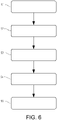
- Fig. 6 is a flow chart of a method for controlling the above described actuator 104.
- a parameter value relating to the desired wheel force such as e.g. a desired wheel torque, of at least one wheel 102 of the vehicle 100 is determined S1.
- the desired wheel force can be determined based on a requested demand from e.g. a vehicle operator, a system for autonomously controlling the vehicle, an ADAS system, etc.
- a torque limit 412 is determined S2.
- a mapping model 402 is determined S3 based on the relationship between the wheel forces and the wheel speed. Further, based on the mapping model 402, a parameter value relating to a desired wheel speed for the at least one wheel 102 is determined S4, whereby the actuator 104 is controlled S5 to generate an operating torque on the at least one wheel.
- the operating torque is subject to the determined torque limit and the desired wheel speed, i.e. the operating torque is thus not allowed to exceed the torque limit.
Landscapes
- Engineering & Computer Science (AREA)
- Transportation (AREA)
- Mechanical Engineering (AREA)
- Combustion & Propulsion (AREA)
- Chemical & Material Sciences (AREA)
- Microelectronics & Electronic Packaging (AREA)
- Physics & Mathematics (AREA)
- Fluid Mechanics (AREA)
- Automation & Control Theory (AREA)
- Power Engineering (AREA)
- Human Computer Interaction (AREA)
- Control Of Driving Devices And Active Controlling Of Vehicle (AREA)
- Regulating Braking Force (AREA)
- Control Of Vehicle Engines Or Engines For Specific Uses (AREA)
- Electric Propulsion And Braking For Vehicles (AREA)
Priority Applications (9)
| Application Number | Priority Date | Filing Date | Title |
|---|---|---|---|
| EP20207778.0A EP4001029A1 (de) | 2020-11-16 | 2020-11-16 | Fahrzeugbewegungsmanagementsystem und aktuatorsteuerungssystem für ein fahrzeug |
| PCT/EP2021/074584 WO2022100907A1 (en) | 2020-11-16 | 2021-09-07 | Vehicle motion management system and motion support device control system |
| US18/252,794 US20240025267A1 (en) | 2020-11-16 | 2021-09-07 | Vehicle motion management system and motion support device control system |
| CN202180076626.9A CN116547180A (zh) | 2020-11-16 | 2021-09-07 | 车辆运动管理系统和运动支持装置控制系统 |
| JP2023527783A JP2023552963A (ja) | 2020-11-16 | 2021-09-07 | 車両運動管理システム及び運動支援装置制御システム |
| KR1020237018517A KR20230107599A (ko) | 2020-11-16 | 2021-09-07 | 차량 모션 관리 시스템 및 모션 지원 장치 제어 시스템 |
| EP21773368.2A EP4244105A1 (de) | 2020-11-16 | 2021-09-07 | Fahrzeugbewegungsverwaltungssystem und bewegungsunterstützungsvorrichtungssteuerungssystem |
| US17/521,935 US11981214B2 (en) | 2020-11-16 | 2021-11-09 | Vehicle motion management system and an actuator control system for a vehicle |
| CN202111338318.7A CN114572213A (zh) | 2020-11-16 | 2021-11-12 | 车辆运动管理系统和用于车辆的致动器控制系统 |
Applications Claiming Priority (1)
| Application Number | Priority Date | Filing Date | Title |
|---|---|---|---|
| EP20207778.0A EP4001029A1 (de) | 2020-11-16 | 2020-11-16 | Fahrzeugbewegungsmanagementsystem und aktuatorsteuerungssystem für ein fahrzeug |
Publications (1)
| Publication Number | Publication Date |
|---|---|
| EP4001029A1 true EP4001029A1 (de) | 2022-05-25 |
Family
ID=73455516
Family Applications (2)
| Application Number | Title | Priority Date | Filing Date |
|---|---|---|---|
| EP20207778.0A Pending EP4001029A1 (de) | 2020-11-16 | 2020-11-16 | Fahrzeugbewegungsmanagementsystem und aktuatorsteuerungssystem für ein fahrzeug |
| EP21773368.2A Pending EP4244105A1 (de) | 2020-11-16 | 2021-09-07 | Fahrzeugbewegungsverwaltungssystem und bewegungsunterstützungsvorrichtungssteuerungssystem |
Family Applications After (1)
| Application Number | Title | Priority Date | Filing Date |
|---|---|---|---|
| EP21773368.2A Pending EP4244105A1 (de) | 2020-11-16 | 2021-09-07 | Fahrzeugbewegungsverwaltungssystem und bewegungsunterstützungsvorrichtungssteuerungssystem |
Country Status (6)
| Country | Link |
|---|---|
| US (2) | US20240025267A1 (de) |
| EP (2) | EP4001029A1 (de) |
| JP (1) | JP2023552963A (de) |
| KR (1) | KR20230107599A (de) |
| CN (2) | CN116547180A (de) |
| WO (1) | WO2022100907A1 (de) |
Citations (3)
| Publication number | Priority date | Publication date | Assignee | Title |
|---|---|---|---|---|
| US20030144777A1 (en) * | 2000-12-30 | 2003-07-31 | Johannes Schmitt | System and method for monitoring the vehicle dynamics of a motor vehicle |
| US20100114447A1 (en) * | 2007-01-18 | 2010-05-06 | Hitach, Ltd. | Automobile and control device for automobile |
| WO2017215751A1 (en) | 2016-06-15 | 2017-12-21 | Volvo Truck Corporation | A wheel controller for a vehicle |
Family Cites Families (5)
| Publication number | Priority date | Publication date | Assignee | Title |
|---|---|---|---|---|
| US8718897B2 (en) * | 2010-03-29 | 2014-05-06 | Wrightspeed, Inc. | Vehicle dynamics control in electric drive vehicles |
| JP6096283B2 (ja) | 2013-04-01 | 2017-03-15 | パイオニア株式会社 | トラクション制御装置及びトラクション制御方法 |
| CN108394313B (zh) | 2018-01-22 | 2020-04-21 | 武汉理工大学 | 一种基于滑移率的四驱电动汽车转矩控制分配方法 |
| CN108422901B (zh) | 2018-05-10 | 2019-11-12 | 吉林大学 | 一种基于整车综合性能最优的电动轮驱动车辆车轮转矩多目标优化方法 |
| JP7411102B2 (ja) | 2020-01-15 | 2024-01-10 | ボルボトラックコーポレーション | 大型車両を動作させる方法 |
-
2020
- 2020-11-16 EP EP20207778.0A patent/EP4001029A1/de active Pending
-
2021
- 2021-09-07 WO PCT/EP2021/074584 patent/WO2022100907A1/en active Application Filing
- 2021-09-07 JP JP2023527783A patent/JP2023552963A/ja active Pending
- 2021-09-07 US US18/252,794 patent/US20240025267A1/en active Pending
- 2021-09-07 CN CN202180076626.9A patent/CN116547180A/zh active Pending
- 2021-09-07 EP EP21773368.2A patent/EP4244105A1/de active Pending
- 2021-09-07 KR KR1020237018517A patent/KR20230107599A/ko active Search and Examination
- 2021-11-09 US US17/521,935 patent/US11981214B2/en active Active
- 2021-11-12 CN CN202111338318.7A patent/CN114572213A/zh active Pending
Patent Citations (3)
| Publication number | Priority date | Publication date | Assignee | Title |
|---|---|---|---|---|
| US20030144777A1 (en) * | 2000-12-30 | 2003-07-31 | Johannes Schmitt | System and method for monitoring the vehicle dynamics of a motor vehicle |
| US20100114447A1 (en) * | 2007-01-18 | 2010-05-06 | Hitach, Ltd. | Automobile and control device for automobile |
| WO2017215751A1 (en) | 2016-06-15 | 2017-12-21 | Volvo Truck Corporation | A wheel controller for a vehicle |
Non-Patent Citations (1)
| Title |
|---|
| "Tyre and vehicle dynamics", 2012, ELSEVIER LTD. |
Also Published As
| Publication number | Publication date |
|---|---|
| KR20230107599A (ko) | 2023-07-17 |
| US11981214B2 (en) | 2024-05-14 |
| CN114572213A (zh) | 2022-06-03 |
| JP2023552963A (ja) | 2023-12-20 |
| EP4244105A1 (de) | 2023-09-20 |
| WO2022100907A1 (en) | 2022-05-19 |
| US20220153146A1 (en) | 2022-05-19 |
| CN116547180A (zh) | 2023-08-04 |
| US20240025267A1 (en) | 2024-01-25 |
Similar Documents
| Publication | Publication Date | Title |
|---|---|---|
| EP3851345B1 (de) | Radschlupfbasierte fahrzeugbewegungsverwaltung für schwerlastfahrzeuge | |
| EP3472008B1 (de) | Radsteuergerät für ein fahrzeug | |
| JP5970322B2 (ja) | 車両の運動制御装置 | |
| EP1470017B1 (de) | Integriertes fahrzeugbewegungssteuersystem | |
| US10981571B2 (en) | Methods and system for operating a vehicle | |
| KR20220125810A (ko) | 스피드 리미트를 갖는 토크 요청에 기반하는 차량 모션 관리 | |
| US11794747B2 (en) | Method for controlling an actuator of a vehicle | |
| US20140379220A1 (en) | Vehicle with independently driven multiple axes, and controller which independently drives multiple axles | |
| JP2016182959A (ja) | 車両の運動制御装置 | |
| US20220135040A1 (en) | Vehicle motion management system and a motion support system for a vehicle | |
| JP2018030582A (ja) | 車両の運動制御装置、及び運動制御プログラム | |
| KR20230033589A (ko) | 동적으로 구성된 사이드슬립 리미트에 기반한 차량 제어 | |
| EP2885188B1 (de) | System und verfahren zur auswahl eines antriebsstrang-getriebe-verhältnisses | |
| EP4001029A1 (de) | Fahrzeugbewegungsmanagementsystem und aktuatorsteuerungssystem für ein fahrzeug | |
| JP2019142491A (ja) | 車両の運動制御装置 | |
| US20240286615A1 (en) | A method for controlling propulsion of a heavy-duty vehicle | |
| JP2023060823A (ja) | 大型車両用車輪スリップブースト機能 | |
| JP2008199847A (ja) | 駆動力制御装置及び車輪の摩擦情報推定装置 |
Legal Events
| Date | Code | Title | Description |
|---|---|---|---|
| PUAI | Public reference made under article 153(3) epc to a published international application that has entered the european phase |
Free format text: ORIGINAL CODE: 0009012 |
|
| STAA | Information on the status of an ep patent application or granted ep patent |
Free format text: STATUS: THE APPLICATION HAS BEEN PUBLISHED |
|
| AK | Designated contracting states |
Kind code of ref document: A1 Designated state(s): AL AT BE BG CH CY CZ DE DK EE ES FI FR GB GR HR HU IE IS IT LI LT LU LV MC MK MT NL NO PL PT RO RS SE SI SK SM TR |
|
| STAA | Information on the status of an ep patent application or granted ep patent |
Free format text: STATUS: REQUEST FOR EXAMINATION WAS MADE |
|
| 17P | Request for examination filed |
Effective date: 20221118 |
|
| RBV | Designated contracting states (corrected) |
Designated state(s): AL AT BE BG CH CY CZ DE DK EE ES FI FR GB GR HR HU IE IS IT LI LT LU LV MC MK MT NL NO PL PT RO RS SE SI SK SM TR |
|
| STAA | Information on the status of an ep patent application or granted ep patent |
Free format text: STATUS: EXAMINATION IS IN PROGRESS |
|
| 17Q | First examination report despatched |
Effective date: 20240531 |