EP4001016A1 - Vehicle lamp, radar module, and vehicle - Google Patents
Vehicle lamp, radar module, and vehicle Download PDFInfo
- Publication number
- EP4001016A1 EP4001016A1 EP20840000.2A EP20840000A EP4001016A1 EP 4001016 A1 EP4001016 A1 EP 4001016A1 EP 20840000 A EP20840000 A EP 20840000A EP 4001016 A1 EP4001016 A1 EP 4001016A1
- Authority
- EP
- European Patent Office
- Prior art keywords
- radar
- vehicle
- lamp
- support member
- concealing part
- Prior art date
- Legal status (The legal status is an assumption and is not a legal conclusion. Google has not performed a legal analysis and makes no representation as to the accuracy of the status listed.)
- Withdrawn
Links
Images


Classifications
-
- F—MECHANICAL ENGINEERING; LIGHTING; HEATING; WEAPONS; BLASTING
- F21—LIGHTING
- F21S—NON-PORTABLE LIGHTING DEVICES; SYSTEMS THEREOF; VEHICLE LIGHTING DEVICES SPECIALLY ADAPTED FOR VEHICLE EXTERIORS
- F21S45/00—Arrangements within vehicle lighting devices specially adapted for vehicle exteriors, for purposes other than emission or distribution of light
- F21S45/10—Protection of lighting devices
-
- B—PERFORMING OPERATIONS; TRANSPORTING
- B60—VEHICLES IN GENERAL
- B60Q—ARRANGEMENT OF SIGNALLING OR LIGHTING DEVICES, THE MOUNTING OR SUPPORTING THEREOF OR CIRCUITS THEREFOR, FOR VEHICLES IN GENERAL
- B60Q1/00—Arrangement of optical signalling or lighting devices, the mounting or supporting thereof or circuits therefor
- B60Q1/0017—Devices integrating an element dedicated to another function
- B60Q1/0023—Devices integrating an element dedicated to another function the element being a sensor, e.g. distance sensor, camera
-
- B—PERFORMING OPERATIONS; TRANSPORTING
- B60—VEHICLES IN GENERAL
- B60Q—ARRANGEMENT OF SIGNALLING OR LIGHTING DEVICES, THE MOUNTING OR SUPPORTING THEREOF OR CIRCUITS THEREFOR, FOR VEHICLES IN GENERAL
- B60Q1/00—Arrangement of optical signalling or lighting devices, the mounting or supporting thereof or circuits therefor
- B60Q1/02—Arrangement of optical signalling or lighting devices, the mounting or supporting thereof or circuits therefor the devices being primarily intended to illuminate the way ahead or to illuminate other areas of way or environments
- B60Q1/04—Arrangement of optical signalling or lighting devices, the mounting or supporting thereof or circuits therefor the devices being primarily intended to illuminate the way ahead or to illuminate other areas of way or environments the devices being headlights
-
- F—MECHANICAL ENGINEERING; LIGHTING; HEATING; WEAPONS; BLASTING
- F21—LIGHTING
- F21S—NON-PORTABLE LIGHTING DEVICES; SYSTEMS THEREOF; VEHICLE LIGHTING DEVICES SPECIALLY ADAPTED FOR VEHICLE EXTERIORS
- F21S41/00—Illuminating devices specially adapted for vehicle exteriors, e.g. headlamps
- F21S41/20—Illuminating devices specially adapted for vehicle exteriors, e.g. headlamps characterised by refractors, transparent cover plates, light guides or filters
- F21S41/28—Cover glass
-
- F—MECHANICAL ENGINEERING; LIGHTING; HEATING; WEAPONS; BLASTING
- F21—LIGHTING
- F21S—NON-PORTABLE LIGHTING DEVICES; SYSTEMS THEREOF; VEHICLE LIGHTING DEVICES SPECIALLY ADAPTED FOR VEHICLE EXTERIORS
- F21S41/00—Illuminating devices specially adapted for vehicle exteriors, e.g. headlamps
- F21S41/20—Illuminating devices specially adapted for vehicle exteriors, e.g. headlamps characterised by refractors, transparent cover plates, light guides or filters
- F21S41/2805—Cover glass
-
- G—PHYSICS
- G01—MEASURING; TESTING
- G01S—RADIO DIRECTION-FINDING; RADIO NAVIGATION; DETERMINING DISTANCE OR VELOCITY BY USE OF RADIO WAVES; LOCATING OR PRESENCE-DETECTING BY USE OF THE REFLECTION OR RERADIATION OF RADIO WAVES; ANALOGOUS ARRANGEMENTS USING OTHER WAVES
- G01S13/00—Systems using the reflection or reradiation of radio waves, e.g. radar systems; Analogous systems using reflection or reradiation of waves whose nature or wavelength is irrelevant or unspecified
- G01S13/88—Radar or analogous systems specially adapted for specific applications
- G01S13/93—Radar or analogous systems specially adapted for specific applications for anti-collision purposes
- G01S13/931—Radar or analogous systems specially adapted for specific applications for anti-collision purposes of land vehicles
-
- G—PHYSICS
- G01—MEASURING; TESTING
- G01S—RADIO DIRECTION-FINDING; RADIO NAVIGATION; DETERMINING DISTANCE OR VELOCITY BY USE OF RADIO WAVES; LOCATING OR PRESENCE-DETECTING BY USE OF THE REFLECTION OR RERADIATION OF RADIO WAVES; ANALOGOUS ARRANGEMENTS USING OTHER WAVES
- G01S7/00—Details of systems according to groups G01S13/00, G01S15/00, G01S17/00
- G01S7/02—Details of systems according to groups G01S13/00, G01S15/00, G01S17/00 of systems according to group G01S13/00
- G01S7/027—Constructional details of housings, e.g. form, type, material or ruggedness
-
- G—PHYSICS
- G01—MEASURING; TESTING
- G01S—RADIO DIRECTION-FINDING; RADIO NAVIGATION; DETERMINING DISTANCE OR VELOCITY BY USE OF RADIO WAVES; LOCATING OR PRESENCE-DETECTING BY USE OF THE REFLECTION OR RERADIATION OF RADIO WAVES; ANALOGOUS ARRANGEMENTS USING OTHER WAVES
- G01S13/00—Systems using the reflection or reradiation of radio waves, e.g. radar systems; Analogous systems using reflection or reradiation of waves whose nature or wavelength is irrelevant or unspecified
- G01S13/88—Radar or analogous systems specially adapted for specific applications
- G01S13/93—Radar or analogous systems specially adapted for specific applications for anti-collision purposes
- G01S13/931—Radar or analogous systems specially adapted for specific applications for anti-collision purposes of land vehicles
- G01S2013/9327—Sensor installation details
- G01S2013/93271—Sensor installation details in the front of the vehicles
-
- G—PHYSICS
- G01—MEASURING; TESTING
- G01S—RADIO DIRECTION-FINDING; RADIO NAVIGATION; DETERMINING DISTANCE OR VELOCITY BY USE OF RADIO WAVES; LOCATING OR PRESENCE-DETECTING BY USE OF THE REFLECTION OR RERADIATION OF RADIO WAVES; ANALOGOUS ARRANGEMENTS USING OTHER WAVES
- G01S13/00—Systems using the reflection or reradiation of radio waves, e.g. radar systems; Analogous systems using reflection or reradiation of waves whose nature or wavelength is irrelevant or unspecified
- G01S13/88—Radar or analogous systems specially adapted for specific applications
- G01S13/93—Radar or analogous systems specially adapted for specific applications for anti-collision purposes
- G01S13/931—Radar or analogous systems specially adapted for specific applications for anti-collision purposes of land vehicles
- G01S2013/9327—Sensor installation details
- G01S2013/93277—Sensor installation details in the lights
Definitions
- the present disclosure relates to a vehicle lamp, a radar module, and a vehicle.
- the present disclosure relates to a vehicle lamp, a radar module, and a vehicle on which a radar, such as a millimeter-wave radar and a microwave radar, is mounted.
- Patent Literature 1 There is known a technique for mounting, on a vehicle lamp, a radar, such as a millimeter-wave radar, configured to acquire data indicating surroundings outside a vehicle (for example, see Patent Literature 1).
- a light guide plate made of a resin is disposed in front of a millimeter-wave radar in order to conceal the millimeter-wave radar disposed in a lamp chamber of a vehicle lamp from the outside of the vehicle.
- emission of light from the light guide plate can be visually recognized from the outside of the vehicle.
- the millimeter-wave radar can be concealed from the outside of the vehicle by the light emission from the light guide plate, and an electromagnetic wave from the millimeter-wave radar can be radiated away to the outside of the vehicle from the light guide plate.
- Patent Literature 1 JP2008-186741A
- Patent Literature 1 since it is necessary to prepare the light guide plate for concealing the millimeter-wave radar separately, the number of components of the vehicle lamp and the number of processes for assembling the vehicle lamp increase. With regard to this point, there is scope for improving a vehicle lamp including a radar, such as a millimeter-wave radar, and a concealing part for concealing the radar.
- a radar such as a millimeter-wave radar
- a first object of the present disclosure is to provide a vehicle lamp and a vehicle capable of concealing a radar from the outside of a vehicle with reliability of radar data acquired by the radar ensured.
- a second object of the present disclosure is to provide a vehicle lamp and a vehicle capable of concealing a radar from the outside of a vehicle with reliability of the radar to radiated heat from the outside ensured.
- a third object of the present disclosure is to provide a vehicle lamp, a radar module, and a vehicle capable of concealing a radar from the outside of a vehicle and relatively easy and reliable positioning of the radar to the vehicle.
- a vehicle lamp includes:
- the concealing part is formed integrally with the lamp cover, and a boundary between the concealing part and the lamp cover is out of a field of view of the radar.
- the boundary between the concealing part and the lamp cover is out of the field of view of the radar. Therefore, it is possible to prevent an electromagnetic wave in the field of view of the radar from being reflected by the boundary to a receiving antenna of the radar to have ill effects on the radar data. In this way, it is possible to provide a vehicle lamp capable of concealing a radar from the outside of a vehicle with reliability of radar data acquired by the radar mounted on the vehicle lamp ensured.
- a vehicle lamp includes:
- the radar includes: a front surface; and a rear surface on a side opposite to the front surface.
- a thermal insulation layer having a thermal conductivity lower than the support member is provided between the support member and the rear surface of the radar.
- a vehicle lamp includes:
- an electromagnetic-wave absorption cover configured to absorb an electromagnetic wave emitted from the radar surrounds the antenna part of the radar. Therefore, it is possible to prevent an electromagnetic wave in a field of view of the radar from being reflected by the concealing part or another optical component to the radar to have ill effects on the radar data. In this way, it is possible to provide a vehicle lamp capable of concealing a radar from the outside of the vehicle with reliability of radar data acquired by the radar mounted on the vehicle lamp ensured.
- a vehicle lamp includes:
- the concealing part is formed integrally with the lamp cover.
- the positioning part is formed integrally with the concealing part and is between the concealing part and the radar.
- the position of the radar to the concealing part is determined by the positioning part formed integrally with the concealing part, and the concealing part is formed integrally with the lamp cover.
- the radar is also positioned to the vehicle. Therefore, it is possible to provide a vehicle lamp capable of concealing a radar from the outside of a vehicle and relatively easy and reliable positioning of the radar to the vehicle.
- a vehicle lamp includes:
- the concealing part is formed integrally with the lamp cover.
- the positioning part is formed integrally with the concealing part and is between the concealing part and the support member.
- the support member is positioned to the concealing part by the positioning part formed integrally with the concealing part, the concealing part is formed integrally with the lamp cover, and the radar is fixed and supported by the support member.
- the radar is also positioned to the vehicle. Therefore, it is possible to provide a vehicle lamp capable of concealing a radar from the outside of a vehicle and relatively easy and reliable positioning of the radar to the vehicle.
- a radar module includes:
- At least one of the concealing part and the support member includes a positioning part configured to position the radar module to the vehicle lamp.
- the radar module can be positioned to the vehicle lamp by the positioning part. If the vehicle lamp has been positioned to the vehicle the radar is positioned to the vehicle when the radar module is positioned to the vehicle lamp. Therefore, it is possible to provide the radar module capable of concealing a radar from the outside of a vehicle and relatively easy and reliable positioning of the radar to the vehicle.
- a vehicle lamp and a vehicle capable of concealing a radar from the outside of a vehicle with reliability of the radar to radiated heat from the outside ensured.
- a vehicle lamp capable of concealing a radar from the outside of a vehicle and relatively easy and reliable positioning of the radar to the vehicle.
- a "left-right direction,” an "up-down direction,” and a “front-rear direction” will be referred to as appropriate for the sake of convenience. These directions are relative directions set for a vehicle 1 shown in FIG. 1 .
- the "left-right direction” includes a “left direction” and a “right direction.”
- the "up-down direction” includes an “up direction” and a “down direction.”
- the "front-rear direction” includes a "front direction” and a “rear direction.”
- the "front-rear direction” (not shown in FIG. 1 ) is perpendicular to the left-right direction and the up-down direction.
- a "horizontal direction" of the vehicle 1 will be referred to which is perpendicular to the up-down direction (vertical direction) and includes the left-right direction and the front-rear direction. Further, in the present embodiment, directions (left-right direction, up-down direction, and front-rear direction) set for a right vehicle lamp 2R and a left vehicle lamp 2L coincide with directions (left-right direction, up-down direction, and front-rear direction) set for the vehicle 1.
- FIG. 1 is a front view of the vehicle 1 including a left vehicle lamp 2L and a right vehicle lamp 2R.
- the left vehicle lamp 2L is on a front left side of the vehicle 1
- the right vehicle lamp 2R is on a front right side of the vehicle 1.
- Each of the left vehicle lamp 2L and the right vehicle lamp 2R includes: a low-beam illumination unit 3; a high-beam illumination unit 4; a radar 5; and a concealing part 6 configured to conceal the radar 5.
- the left vehicle lamp 2L is similar to the right vehicle lamp 2R. Therefore, in the following, the right vehicle lamp 2R will be described with reference to FIG. 2 .
- the left vehicle lamp 2L and the right vehicle lamp 2R will be generically referred to as a "vehicle lamp 2" simply.
- the low-beam illumination unit 3 is configured to emit a low-beam light distribution pattern toward the front of the vehicle 1.
- the high-beam illumination unit 4 is configured to emit a high-beam light distribution pattern toward the front of the vehicle 1.
- the radar 5 is configured to acquire radar data indicating surroundings of the vehicle 1 by emitting an electromagnetic wave (for example, a millimeter wave and a microwave) outside the vehicle 1.
- the radar 5 is, for example, a millimeter-wave radar or a microwave radar.
- a vehicle control unit in-vehicle computer, not shown is configured to catch the surroundings of the vehicle 1 (in particular, information on an object outside the vehicle 1) based on the radar data output from the radar 5.
- the radar 5 includes an antenna part 53 and a communication circuit part 54 (see FIG. 5A ).
- the antenna part 53 includes: one or more transmission antennae configured to emit an electromagnetic wave (for example, a millimeter wave having a wavelength of 1 mm to 10 mm) to the air; and one or more receiving antennae configured to receive a reflected electromagnetic wave reflected by an object.
- the antenna part 53 may be configured with a patch antenna (a metal pattern formed on a substrate). An emitted electromagnetic wave emitted from the transmission antennae are reflected by an object, such as another vehicle, and then the reflected electromagnetic wave from the object is received by the receiving antennae.
- the communication circuit part 54 includes: a transmission radio frequency (RF) circuit; a receiving RF circuit; and a signal processing circuit.
- the communication circuit part is configured with a monolithic microwave integrated circuit (MMIC).
- MMIC monolithic microwave integrated circuit
- the transmission RF circuit is electrically connected to the transmission antennae.
- the receiving RF circuit is electrically connected to the receiving antennae.
- the signal processing circuit is configured to generate radar data by processing a digital signal output from the receiving RF circuit.
- the antenna part 53 and the communication circuit part 54 may be accommodated in a case.
- the antenna part 53 may be covered with a radome.
- the concealing part 6 faces the radar 5 to conceal the radar 5 from the outside of the vehicle 1.
- the concealing part 6 is configured to let an electromagnetic wave emitted from the radar 5 through.
- the concealing part 6 may be configured with, for example, an opaque resin member.
- the concealing part 6 may be configured with a resin member colored in a predetermined color, such as black.
- the concealing part 6 may be configured with a reflex reflector having a large number of fine prisms. In this case, since light from the outside is totally reflected by the prisms of the reflex reflector, the radar 5 can be concealed from the outside by the reflex reflector. Therefore, the radar 5 can be concealed from the outside of the vehicle 1 by the concealing part 6, thereby improving exterior design of the right vehicle lamp 2R.
- FIG. 2 is a cross sectional view of the right vehicle lamp 2R in the vertical direction (up-down direction).
- the right vehicle lamp 2R further includes: a lamp housing 14; a lamp cover 12 covering an opening of the lamp housing 14; and a support member 8.
- the lamp housing 14 may be configured with, for example, a metal member.
- the lamp cover 12 may be configured with, for example, a transparent resin member.
- the low-beam illumination unit 3 and the high-beam illumination unit 4 are in a lamp chamber S formed by the lamp housing 14 and the lamp cover 12.
- an adaptive driving beam (ADB) illumination unit configured to emit an ADB light distribution pattern having an irradiation region and a non-irradiation region may be disposed in the lamp chamber S.
- ADB adaptive driving beam
- a LiDAR unit or a camera may be disposed in the lamp chamber S.
- the support member 8 is a metal bracket and is configured to support and fix the radar 5.
- the support member 8 is fixed to the lamp housing 14 with screws 22 (see FIG. 4 ).
- the support member 8 extends downward from the lamp housing 14. Since the radar 5 and the support member 8 are outside the lamp chamber S, operation of the radar 5 is suitably prevented from being affected by heat generated from the low-beam illumination unit 3 and the high-beam illumination unit 4.
- the concealing part 6 is formed integrally with the lamp cover 12 and extends downward from the lamp cover 12. Since the concealing part 6 is integrally formed with the lamp cover 12 to obviate the necessity for attaching the concealing part 6 to the right vehicle lamp 2R, the number of processes for assembling the right vehicle lamp 2R can be reduced.
- the concealing part 6 and the lamp cover 12 may be integrally formed by two-tone molding using a mold. If the concealing part 6 and the lamp cover 12 are integrally formed by two-tone molding, protrusions C1 and C2 are formed on the concealing part 6 and the lamp cover 12 around a boundary B between the concealing part 6 and the lamp cover 12. Therefore, in the present embodiment, a relative position between the concealing part 6 and the radar 5 is adjusted such that the boundary B between the concealing part 6 and the lamp cover 12 is out of a field of view Fv of the radar 5 in the vertical direction.
- a field of view Fh (see FIG. 4 ) of the radar 5 in the horizontal direction may be, for example, within a range of 120° to 180°.
- the field of view Fh of the radar 5 may be within a range of ⁇ 60° to ⁇ 90° with respect to a center axis of the radar 5.
- the field of view Fv of the radar 5 in the vertical direction may be, for example, within a range of 3° to 100°.
- the field of view of the radar 5 is synonymous with a detection range of the radar 5.
- margin angular region M angular regions adjacent to both ends of the field of view Fv of the radar 5 are defined as margin angular region M. While intensity of electromagnetic waves in the margin angular region M is sufficiently smaller than in the field of view Fv, metal members reflecting the electromagnetic waves cannot be disposed in the margin angular region M.
- the margin angular region M may be, for example, within a range of 3° to 5°.
- the boundary B between the concealing part 6 and the lamp cover 12 is out of the field of view Fv but may be within the margin angular region M.
- a distance d between the concealing part 6 and the radar 5 in the front-rear direction may be from 20 mm to 100 mm. If the distance d between the concealing part 6 and the radar 5 is not smaller than 20 mm, the reflected electromagnetic waves emitted from the radar 5 and reflected by the concealing part 6 are sufficiently weakened before reaching the receiving antennae of the radar 5. Therefore, it is possible to prevent the reflected electromagnetic waves received by the radar 5 from affecting radar data as noise.
- the distance between the concealing part 6 and the radar 5 is not greater than 100 mm, it is possible to prevent some electromagnetic waves in the field of view of the radar 5 from being unable to pass through the concealing part 6. That is, it is possible to prevent some electromagnetic waves unable to pass through the concealing part 6 from being reflected by the boundary B between the concealing part 6 and the lamp cover 12 or by another optical component to have ill effects on the radar data as noise.
- FIG. 3 is a diagram showing reflected electromagnetic waves R1 and R2 reflected by the concealing part 6.
- the reflected electromagnetic wave R2 reflected by one surface 62 of the concealing part 6 facing the radar 5 and the reflected electromagnetic wave R1 reflected by the other surface 63 of the concealing part 6 on a side opposite to the one surface 62 weaken each other.
- a phase difference ⁇ between the reflected electromagnetic waves R2 and R1 is (2 m + 1) ⁇ (where m is a non-negative integer)
- the reflected electromagnetic waves R1 and R2 weaken each other.
- intensity of a reflected electromagnetic wave reflected by the concealing part 6 becomes weak, it is possible to prevent a reflected electromagnetic wave received by the radar 5 from affecting radar data as noise.
- the wavelength ⁇ of the electromagnetic wave of the radar 5 is 3.922 mm
- FIG. 4 is a cross sectional view showing the radar 5, the support member 8, and the concealing part 6 in the horizontal direction.
- the support member 8 is fixed to the lamp housing 14 with the screws 22 as fixing units.
- the radar 5 is supported and fixed by a lance 23 provided in the support member 8.
- the radar 5 includes: a front surface 51; a rear surface 52 on a side opposite to the front surface 51; and side surfaces 55 between the front surface 51 and the rear surface 52.
- the front surface 51, the rear surface 52, and the side surfaces 55 of the radar 5 may be a front surface, a rear surface, and side surfaces of a case of the radar 5, respectively.
- An electromagnetic wave emitted from the antenna part 53 (transmission antenna) of the radar 5 are sent out into air via the front surface 51.
- a reflected electromagnetic wave reflected by an object outside the vehicle 1 enters the antenna part 53 (receiving antenna) via the front surface 51.
- Spacers 20a and 20b are provided between the rear surface 52 of the radar 5 and the support member 8. Thermal conductivity of the spacers 20a and 20b may be lower than the support member 8. As shown in FIG. 5A , the spacer 20a (an example of a first spacer) touches the rear surface 52 and the side surface 55 of the radar 5 and extends in the up-down direction along the side surfaces 55 of the radar 5. Similarly, the spacer 20b (an example of a second spacer) touches the rear surface 52 and the side surface 55 of the radar 5 and extends in the up-down direction along the side surfaces 55 of the radar 5. The spacer 20a faces the spacer 20b in the left-right direction (an example of a first direction) across an air layer 30.
- the air layer 30 (an example of a thermal insulation layer) can be relatively easily provided between the rear surface 52 of the radar 5 and the support member 8.
- the air layer 30 functioning as a thermal insulation layer is provided between the support member 8 and the rear surface 52 of the radar 5, heat radiated from an engine (external heat source) behind the radar 5 is less transferred to the rear surface 52 of the radar 5 via the support member 8. In this way, it is possible to suitably prevent operation performance of the radar 5 (particularly, communication circuit part 54) from declining due to the heat radiated from the engine. Therefore, it is possible to conceal the radar 5 from the outside of the vehicle 1 with reliability of the radar 5 to heat radiated from the outside ensured.
- the rear surface 52 of the radar 5 directly touches the support member 8. In this case, heat radiated from the engine is easily transferred from the support member 8 having a high thermal conductivity to the rear surface 52 of the radar 5, thereby the operation performance of the radar 5 significantly declining due to the heat radiated from the engine.
- the spacers 20a and 20b may be configured with a member having a thermal conductivity lower than the support member 8, which is made of a metal member.
- each of the spacers 20c to 20f touches the rear surface 52 and the side surfaces 55 of the radar 5.
- Each of the spacers 20c to 20f may be provided correspondingly to one of four corners of the radar 5.
- the spacer 20d (an example of the second spacer) faces the spacer 20c (an example of the first spacer) in the left-right direction (an example of the first direction) across the air layer 30.
- the spacer 20e (an example of a third spacer) faces the spacer 20c in the up-down direction (an example of a second direction) across the air layer 30.
- the spacer 20f (an example of a fourth spacer) faces the spacer 20d in the up-down direction across the air layer 30 and faces the spacer 20e in the left-right direction across the air layer 30.
- the radar 5 and the concealing part 6 are separated from each other by the distance d (see FIG. 1 ) in the front-rear direction.
- the relative position between the radar 5 and the concealing part 6 is determined by positioning parts 9a and 9b.
- the positioning part 9a is configured to position the support member 8 to the concealing part 6 with a concave 92a provided in the positioning part 9a engaging with a rib 18a provided on a front surface 82 of the support member 8.
- the positioning part 9b is configured to position the support member 8 to the concealing part 6 with a concave 92b provided in the positioning part 9b engaging with a rib 18b provided on the front surface 82 of the support member 8.
- the positioning parts 9a and 9b are formed integrally with the concealing part 6 and are between the concealing part 6 and the radar 5.
- the positioning part 9a faces the positioning part 9b across the radar 5 in the left-right direction.
- the radar 5 since the support member 8 is positioned to the concealing part 6 by the two positioning parts 9a and 9b, when the vehicle lamp 2 is positioned to the vehicle 1, the radar 5 is also positioned to the vehicle 1. Therefore, the radar 5 can be relatively easily and reliably positioned to the vehicle 1 by the positioning parts 9a and 9b.
- a support member 8a according to a modification will be described with reference to FIG. 6 .
- the support member 8a of the present modification it is possible to provide an air layer 30a between the support member 8a and the rear surface 52 of the radar 5 without a spacer.
- the rear surface 52 of the radar 5 directly touches the front surface 82 of the support member 8a.
- the support member 8a has a convex 85 protruding from a rear surface 83 on a side opposite to the front surface 82 of the support member 8a.
- the air layer 30a (an example of the thermal insulation layer) is provided between the rear surface 52 of the radar 5 and the convex 85 facing the rear surface 52.
- the side surfaces 55 of the radar 5 touch step parts 87a and 87b formed on the support member 8a.
- the radar 5 can be positioned to the support member 8 with the side surfaces 55 and the rear surface 52 of the radar 5 touching the step parts 87a and 87b.
- the air layer 30a can be relatively easily provided between the support member 8a and the rear surface 52 of the radar 5 by the convex 85 of the support member 8a.
- FIG. 7 is a cross sectional view of the right vehicle lamp 200R according to the modification in the vertical direction.
- the right vehicle lamp 200R according to the modification is mainly different from the right vehicle lamp 2R according to the present embodiment in that the radar 5 and a support member 80 are in the lamp chamber S.
- the right vehicle lamp 200R includes: a lamp housing 140; a lamp cover 120 covering an opening of the lamp housing 140; the low-beam illumination unit 3 disposed in the lamp chamber S formed by the lamp housing 140 and the lamp cover 120; and a high-beam illumination unit (not shown).
- the right vehicle lamp 200R further includes: the radar 5; the support member 80 that is fixed to the lamp housing 140 and supports and fixes the radar 5; and a concealing part 60 facing the radar 5 to conceal the radar 5 from the outside of the vehicle 1.
- the concealing part 60 is formed integrally with the lamp cover 120 and extends downward from the lamp cover 120.
- the concealing part 60 and the lamp cover 120 may be integrally formed by two-tone molding using a mold. If the concealing part 60 and the lamp cover 120 are integrally formed by two-tone molding, protrusions C3 and C4 are formed on the concealing part 60 and the lamp cover 120 around a boundary B2 between the concealing part 60 and the lamp cover 120. Therefore, in the present modification, a relative position between the concealing part 60 and the radar 5 is adjusted such that the boundary B2 between the concealing part 60 and the lamp cover 120 is out of the field of view Fv of the radar 5 in the vertical direction.
- the boundary B2 between the concealing part 60 and the lamp cover 120 is out of the field of view Fv of the radar 5, it is possible to prevent an electromagnetic wave in the field of view Fv of the radar 5 from being reflected by the protrusions C3 and C4 to the receiving antenna of the radar 5 to have ill effects on radar data. Therefore, it is possible to conceal the radar 5 from the outside of the vehicle 1 with reliability of the radar data acquired by the radar 5 mounted on the right vehicle lamp 200R ensured.
- the boundary B2 between the concealing part 6 and the lamp cover 120 is out of the field of view Fv but may be within the margin angular region M.
- the radar 5 since the radar 5 is in the lamp chamber, it is possible to prevent the right vehicle lamp 200R from getting bigger suitably.
- the present embodiment a second embodiment of the present disclosure (hereinafter, simply referred to as "the present embodiment") will be described with reference to the drawings.
- Dimensions of components shown in the drawings may be different from actual dimensions of the components for the sake of convenience. Detailed description of components having the same reference numerals as in the first embodiment will not be repeated.
- FIG. 8 is a front view of the vehicle 1A including a left vehicle lamp 102L and a right vehicle lamp 102R.
- the left vehicle lamp 102L is on the front left side of the vehicle 1A
- the right vehicle lamp 102R is on the front right side of the vehicle 1A.
- Each of the left vehicle lamp 102L and the right vehicle lamp 102R includes: the low-beam illumination unit 3; the high-beam illumination unit 4; the radar 5; and the concealing part 6 configured to conceal the radar 5.
- the left vehicle lamp 102L is similar to the right vehicle lamp 102R. Therefore, in the following, the right vehicle lamp 102R will be described with reference to FIG. 9 .
- the left vehicle lamp 102L and the right vehicle lamp 102R will be generically referred to as a "vehicle lamp 102" simply.
- FIG. 9 is a cross sectional view of the right vehicle lamp 102R in the vertical direction (up-down direction). As shown in FIG. 9 , the right vehicle lamp 102R further includes: the lamp housing 14; the lamp cover 12 covering the opening of the lamp housing 14; the support member 8; and an electromagnetic-wave absorption cover 7.
- FIG. 10 is a front view showing only the electromagnetic-wave absorption cover 7 and the radar 5.
- FIG. 11 is a cross sectional view showing the radar 5, the support member 8, the concealing part 6, and the electromagnetic-wave absorption cover 7 in the horizontal direction.
- the support member 8 is fixed to the lamp housing 14 with the screws 22 as fixing units.
- the radar 5 is supported and fixed by the lance 23 (an example of an elastic engagement member) provided in the support member 8.
- the radar 5 includes: the front surface 51; the rear surface 52 on the side opposite to the front surface 51; and the side surfaces 55 between the front surface 51 and the rear surface 52.
- An electromagnetic wave emitted from the antenna part 53 of the radar 5 are sent out into air via the front surface 51.
- the spacers 20a and 20b are provided between the radar 5 and the support member 8.
- the thermal conductivity of the spacers 20a and 20b may be lower than the support member 8.
- the spacer 20a faces the spacer 20b in the left-right direction.
- Each of the spacers 20a and 20b touch the rear surface 52 and the side surfaces 55. In this way, since the two spacers 20a and 20b separated from each other are provided between the radar 5 and the support member 8, the air layer 30 (an example of a thermal insulation layer) is provided between the rear surface 52 of the radar 5 and the support member 8.
- the electromagnetic-wave absorption cover 7 is configured to absorb an electromagnetic wave emitted from the antenna part 53 of the radar 5.
- the electromagnetic-wave absorption cover 7 includes: a frustum-shaped cover body 73; and an electromagnetic-wave absorption sheet 72 provided on an inner surface of the cover body 73.
- the cover body 73 may be formed of, for example, a resin material.
- the electromagnetic-wave absorption sheet 72 may be formed of: an inorganic binder; and electromagnetic-wave absorption particles provided in the inorganic binder.
- the electromagnetic-wave absorption particles epsilon iron oxide particles or titanium oxide particles may be adopted. If the electromagnetic-wave absorption cover 7 only includes the cover body, the cover body may be formed of a resin material mixed with the electromagnetic-wave absorption particles.
- the electromagnetic-wave absorption cover 7 surrounds and is out of the field of view F (the field of view Fh in the horizontal direction and the field of view Fv in the vertical direction) of the radar 5.
- the electromagnetic-wave absorption cover 7 surrounds the antenna part 53 of the radar 5 and is fixed to the support member 8 with screws 24 (fixing units).
- an end of the cover body 73 of the electromagnetic-wave absorption cover 7 is fixed to the rib 18a or 18b on the support member 8 with the screws 24.
- the electromagnetic-wave absorption cover 7 is between the concealing part 6 and the radar 5 in the front-rear direction to be concealed from the outside of the vehicle 1A by the concealing part 6. In this way, since the electromagnetic-wave absorption cover 7 and the radar 5 can be concealed from the outside of the vehicle 1A by the concealing part 6, exterior design of the right vehicle lamp 102R can be suitably prevented from being impaired.
- the electromagnetic-wave absorption cover 7 configured to absorb electromagnetic waves emitted from the radar 5 surrounds the antenna part 53 of the radar 5. Therefore, it is possible to prevent an electromagnetic wave in the field of view F of the radar 5 from being reflected by the concealing part 6 or another optical component to the antenna part (particularly, the receiving antenna) of the radar 5 to have ill effects on radar data suitably. In this way, it is possible to provide the right vehicle lamp 102R capable of concealing the radar 5 from the outside of the vehicle 1A with reliability of radar data acquired by the radar 5 mounted on the right vehicle lamp 102R ensured.
- the radar 5 can reliably receive a reflected electromagnetic wave reflected by an object outside the vehicle 1A and, by the electromagnetic-wave absorption cover 7, can reliably avert reception of the reflected electromagnetic waves reflected by optical components in the right vehicle lamp 102R.
- the electromagnetic-wave absorption cover 7 is out of the field of view F of the radar 5, it is possible to prevent an electromagnetic wave in the field of view F directly emitted from the radar 5 from being absorbed by the electromagnetic-wave absorption cover 7. Further, since the electromagnetic-wave absorption cover 7 is fixed by the support member 8, it is possible to position the electromagnetic-wave absorption cover 7 to the radar 5 (the antenna part 53) precisely.
- the present embodiment a third embodiment of the present disclosure (hereinafter, simply referred to as "the present embodiment") will be described with reference to the drawings.
- Dimensions of components shown in the drawings may be different from actual dimensions of the components for the sake of convenience. Detailed description of components having the same reference numerals as in the first or second embodiment will not be repeated.
- FIG. 12 is a front view of the vehicle 1B including a left vehicle lamp 202L and a right vehicle lamp 202R.
- the left vehicle lamp 202L is on the front left side of the vehicle 1
- the right vehicle lamp 202R is on the front right side of the vehicle 1B.
- Each of the left vehicle lamp 202L and the right vehicle lamp 202R includes: the low-beam illumination unit 3; the high-beam illumination unit 4; the radar 5; and the concealing part 6 configured to conceal the radar 5.
- the left vehicle lamp 202L is similar to the right vehicle lamp 202R. Therefore, in the following, the right vehicle lamp 202R will be described with reference to FIG. 13 .
- the left vehicle lamp 202L and the right vehicle lamp 202R will be generically referred to as a "vehicle lamp 202" simply.
- FIG. 13 is a cross sectional view of the right vehicle lamp 202R in the vertical direction (up-down direction).
- the right vehicle lamp 202R further includes: the lamp housing 14; the lamp cover 12 covering the opening of the lamp housing 14; and the support member 8.
- the lamp housing 14 may be configured with, for example, a metal member.
- the lamp cover 12 may be configured with, for example, a transparent resin member.
- the low-beam illumination unit 3 and the high-beam illumination unit 4 are in the lamp chamber S formed by the lamp housing 14 and the lamp cover 12.
- FIG. 14 is a cross sectional view showing the radar 5, the support member 8, and the concealing part 6 in the horizontal direction.
- the support member 8 is fixed to the lamp housing 14 with the screws 22 as fixing units.
- the radar 5 is supported and fixed by the lance 23 provided in the support member 8.
- the radar 5 includes: the front surface 51; the rear surface 52 on the side opposite to the front surface 51; and the side surfaces 55 between the front surface 51 and the rear surface 52.
- the front surface 51, the rear surface 52, and the side surfaces 55 of the radar 5 may be the front surface, the rear surface, and the side surfaces of the case of the radar 5, respectively.
- An electromagnetic wave emitted from the antenna part 53 (transmission antenna) of the radar 5 are sent out into air via the front surface 51.
- a reflected electromagnetic wave reflected by an object outside the vehicle 1B enters the antenna part 53 (receiving antenna) via the front surface 51.
- Spacers 120a and 120b are provided between the rear surface 52 of the radar 5 and the support member 8. Thermal conductivity of the spacers 120a and 120b may be lower than the support member 8.
- the spacer 120a touches the rear surface 52 of the radar 5 and extends in the up-down direction along the side surfaces 55 of the radar 5.
- the spacer 120b touches the rear surface 52 of the radar 5 and extends in the up-down direction along the side surfaces 55 of the radar 5.
- the spacer 120a faces the spacer 120b in the left-right direction across the air layer 30
- the air layer 30 (an example of a thermal insulation layer) can be relatively easily provided between the rear surface 52 of the radar 5 and the support member 8
- the air layer 30 functioning as a thermal insulation layer is provided between the support member 8 and the rear surface 52 of the radar 5, heat radiated from the engine (external heat source) behind the radar 5 is less transferred to the rear surface 52 of the radar 5 via the support member 8. In this way, it is possible to suitably prevent operation performance of the radar 5 (particularly, communication circuit part 54) from declining due to the heat radiated from the engine. Therefore, it is possible to conceal the radar 5 from the outside of the vehicle 1B with reliability of the radar 5 to heat radiated from the outside ensured.
- the rear surface 52 of the radar 5 directly touches the support member 8. In this case, heat radiated from the engine is easily transferred from the support member 8 having a high thermal conductivity to the rear surface 52 of the radar 5, thereby the operation performance of the radar 5 significantly declining due to the heat radiated from the engine.
- the spacers 20a and 20b may be configured with a member having a thermal conductivity lower than the support member 8, which is made of a metal member.
- FIG. 15 is a front view showing the positioning parts 19a to 19d, the radar 5, and the concealing part 6. As shown in FIGS. 14 and 15 , each of the positioning parts 19a to 19d touches the radar 5 to position the radar 5 to the concealing part 6. In other words, the relative position between the radar 5 and the concealing part 6 is determined by the positioning parts 19a to 19d.
- Each of the positioning parts 19a to 19d has a concave configured to touch the front surface 51 and the side surface 55 of the radar 5.
- the positioning part 19a has a concave 192a configured to touch the front surface 51 and the side surface 55
- the positioning part 19b has a concave 192b configured to touch the front surface 51 and the side surface 55.
- the support member 8 configured to support the radar 5 is fixed to the lamp housing 14 with the screws 22. In this way, by the positioning parts 19a to 19d, the radar 5 can be positioned to the concealing part 6 reliably.
- Each of the positioning parts 19a to 19d is formed integrally with the concealing part 6 and is between the concealing part 6 and the radar 5 in the front-rear direction.
- the positioning parts 19a to 19d may be formed of the same material (for example, an opaque resin material) as the concealing part 6.
- the concealing part 6 and the positioning parts 19a to 19d may be integrally formed by injection molding using a mold.
- the positioning part 19a (an example of a first positioning part) faces the positioning part 19b (an example of a second positioning part) in the left-right direction.
- the radar 5 is between the positioning part 19a and the positioning part 19b in the left-right direction.
- the positioning part 19c faces the positioning part 19a in the up-down direction.
- the positioning part 19d faces the positioning part 19b in the up-down direction and faces the positioning part 19c in the left-right direction.
- the number of positioning parts is not limited to four.
- the number of positioning parts may be two. In this case, it is preferable that one of the two positioning parts face the other positioning part across the radar 5 in the left-right direction. Further, the two positioning parts may extend along the side surfaces 55 of the radar 5. By providing two or more positioning parts, the radar 5 can be positioned to the concealing part 6 reliably.
- the radar 5 is positioned to the concealing part 6 by the positioning parts 19a to 19d formed integrally with the concealing part 6, and the concealing part 6 is formed integrally with the lamp cover 12.
- the radar 5 is also positioned to the vehicle 1B. Therefore, the radar 5 can be relatively easily and reliably positioned to the vehicle 1B with the radar 5 concealed from the outside of the vehicle 1B.
- FIG. 16 is a cross sectional view showing the radar 5, the support member 8, and the concealing part 6 in the horizontal direction.
- FIG. 17 is a front view showing the positioning parts 29a to 29d according to the modification, the radar 5, and the concealing part 6.
- each of the positioning parts 29a to 29d touches the support member 8 configured to support and fix the radar 5 to position the support member 8 to the concealing part 6.
- the relative position between the radar 5 and the concealing part 6 is determined in accordance with a relative position between the support member 8 and the concealing part 6.
- Each of the positioning parts 29a to 29d has a concave configured to touch the rib 18a or 18b protruding from the front surface 82 of the support member 8.
- the positioning part 29a has a concave 94a configured to touch a front surface 180a and a side surface 182a of the rib 18a.
- the positioning part 29b has a concave 94b configured to touch a front surface 180b and a side surface 182b of the rib 18b.
- the support member 8 is fixed to the lamp housing 14 with the screws 22. In this way, by the positioning parts 29a to 29d, the support member 8 can be positioned to the concealing part 6 reliably.
- Each of the positioning parts 29a to 29d is formed integrally with the concealing part 6 and is between the concealing part 6 and the radar 5 in the front-rear direction.
- the positioning parts 29a to 29d may be formed of the same material (for example, an opaque resin material) as the concealing part 6.
- the concealing part 6 and the positioning parts 29a to 29d may be integrally formed by injection molding using a mold
- the positioning part 29a (an example of the first positioning part) faces the positioning part 29b (an example of the second positioning part) in the left-right direction.
- the radar 5 is between the positioning part 29a and the positioning part 29b in the left-right direction.
- the positioning part 29c faces the positioning part 29a in the up-down direction.
- the positioning part 29d faces the positioning part 29b in the up-down direction and faces the positioning part 29c in the left-right direction
- the number of positioning parts is not limited to four.
- the number of positioning parts may be two. In this case, it is preferable that one of the two positioning parts face the other positioning part across the radar 5 in the left-right direction. Further, the two positioning parts may extend along the side surfaces 182a or 182b of the rib 18a or 18b of the support member 8.
- the support member 8 is positioned to the concealing part 6 by the positioning parts 29a to 29d formed integrally with the concealing part 6.
- the concealing part 6 is formed integrally with the lamp cover 12, and the radar 5 is fixed by the support member 8.
- the radar 5 is also positioned to the vehicle 1B. Therefore, the radar 5 can be relatively easily and reliably positioned to the vehicle 1B with the radar 5 concealed from the outside of the vehicle 1B.
- the present embodiment a fourth embodiment of the present disclosure (hereinafter, simply referred to as "the present embodiment") will be described with reference to the drawings.
- Dimensions of components shown in the drawings may be different from actual dimensions of the components for the sake of convenience. Detailed description of components having the same reference numerals as in the first to third embodiments will not be repeated.
- FIG. 18 is a front view of the vehicle 1C including a left vehicle lamp 302L and a right vehicle lamp 302R. As shown in FIG. 18 , the left vehicle lamp 302L is on the front left side of the vehicle 1, and the right vehicle lamp 302R is on the front right side of the vehicle 1. Each of the left vehicle lamp 302L and the right vehicle lamp 302R includes the low-beam illumination unit 3 and the high-beam illumination unit 4.
- a left radar module 17L is disposed below the left vehicle lamp 302L.
- Arightradar module 17R is disposed below the right vehicle lamp 302R.
- Each of the left radar module 17L and the right radar module 17R includes: the radar 5; and a concealing part 6a configured to conceal the radar 5.
- the left vehicle lamp 302L is similar to the right vehicle lamp 302R. Therefore, in the following, the right vehicle lamp 302R will be described with reference to FIG. 19 .
- the left vehicle lamp 302L and the right vehicle lamp 302R will be generically referred to as a "vehicle lamp 302" simply.
- the left radar module 17L is similar to the right radar module 17R. Therefore, in the following, the right radar module 17R will be described with reference to FIG. 19 .
- the left radar module 17L and the right radar module 17R will be generically referred to as "a radar module 17" simply.
- the concealing part 6a faces the radar 5 to conceal the radar 5 from the outside of the vehicle 1C.
- the concealing part 6a is configured to let an electromagnetic wave emitted from the radar 5 through.
- the concealing part 6a may be configured with, for example, an opaque resin member.
- the concealing part 6a may be configured with a resin member colored in a predetermined color, such as black.
- the concealing part 6a may be configured with a reflex reflector having a large number of fine prisms. In this case, since light from the outside is totally reflected by the prisms of the reflex reflector, the radar 5 can be concealed from the outside by the reflex reflector. Therefore, the radar 5 can be concealed from the outside of the vehicle 1C by the concealing part 6a, thereby improving exterior design of the right vehicle lamp 302R.
- FIG. 19 is a cross sectional view of the right vehicle lamp 302R and the right radar module 17R in the vertical direction (up-down direction).
- the right vehicle lamp 302R further includes: a lamp housing 14a; a lamp cover 12a covering an opening of the lamp housing 14a.
- the lamp housing 14a may be configured with, for example, a metal member.
- the lamp cover 12a may be configured with, for example, a transparent resin member.
- the low-beam illumination unit 3 and the high-beam illumination unit 4 are in a lamp chamber S formed by the lamp housing 14a and the lamp cover 12a.
- an adaptive driving beam (ADB) illumination unit configured to emit an ADB light distribution pattern having an irradiation region and a non-irradiation region may be disposed in the lamp chamber S.
- ADB adaptive driving beam
- a LiDAR unit or a camera may be disposed in the lamp chamber S.
- the right radar module 17R further includes a support member 8a.
- the support member 8a is a metal bracket and is configured to support and fix the radar 5.
- the support member 8a is fixed to the lamp housing 14a with screws 22 (see FIG. 22 ). Since the right radar module 17R is outside the lamp chamber S of the right vehicle lamp 302R, operation of the radar 5 is suitably prevented from being affected by heat generated from the low-beam illumination unit 3 and the high-beam illumination unit 4.
- An upper end of the support member 8a has a positioning part 80a (an example of the second positioning part) configured to engage with a groove 142 formed in the lamp housing 14a.
- the support member 8a extends downward from the lamp housing 14a.
- the positioning part 80a may be configured with, for example, an engagement protrusion extending in the left-right direction.
- the groove 142 may extend in the left-right direction.
- the positioning part 80a is configured to position the right radar module 17R to the right vehicle lamp 302R by engaging with the groove 142. In other words, the right radar module 17R can be positioned to the right vehicle lamp 302R with an outer side surface of the positioning part 80a touching an inner wall surface of the groove 142.
- An upper end of the concealing part 6a has a positioning part 65a (an example of the first positioning part) configured to engage with a groove 122 formed in the lamp cover 12a.
- the concealing part 6a extends downward from the lamp cover 12a.
- the positioning part 65a may be configured with, for example, an engagement protrusion extending in the left-right direction.
- the groove 122 may extend in the left-right direction.
- the positioning part 65a is configured to position the right radar module 17R to the right vehicle lamp 302R by engaging with the groove 122. In other words, the right radar module 17R can be positioned to the right vehicle lamp 302R with an outer side surface of the positioning part 65a touching an inner wall surface of the groove 122.
- a concealing part 6A according to a modification may include a positioning part 65A configured with an engagement groove extending in the left-right direction.
- a lamp cover 12A according to the modification may include an engagement protrusion 122A extending in the left-right direction.
- the positioning part 65A is configured to position the right radar module 17R to the right vehicle lamp 302R by engaging with the engagement protrusion 122A.
- the right radar module 17R can be positioned to the right vehicle lamp 302R with an outer side surface of the engagement protrusion 122A touching an inner wall surface of the positioning part 65A.
- a relative position between the concealing part 6a and the radar 5 may be adjusted such that a boundary between the concealing part 6a and the lamp cover 12a (that is, around the positioning part 65a) is out of the field of view Fv of the radar 5 in the vertical direction.
- a field of view Fh (see FIG. 22 ) of the radar 5 in the horizontal direction may be, for example, within a range of 120° to 180°.
- the field of view Fh of the radar 5 may be within a range of ⁇ 60° to ⁇ 90° with respect to a center axis of the radar 5.
- the field of view Fv of the radar 5 in the vertical direction may be, for example, within a range of 3° to 100°.
- the field of view of the radar 5 is synonymous with a detection range of the radar 5
- a distance d between the concealing part 6a and the radar 5 in the front-rear direction may be from 20 mm to 100 mm. If the distance d between the concealing part 6a and the radar 5 is not smaller than 20 mm, the reflected electromagnetic waves emitted from the radar 5 and reflected by the concealing part 6a are sufficiently weakened before reaching the receiving antennae of the radar 5. Therefore, it is possible to prevent the reflected electromagnetic waves received by the radar 5 from affecting radar data as noise
- the distance between the concealing part 6a and the radar 5 is not greater than 100 mm, it is possible to prevent some electromagnetic waves in the field of view of the radar 5 from being unable to pass through the concealing part 6a. That is, it is possible to prevent some electromagnetic waves unable to pass through the concealing part 6a from being reflected by the boundary between the concealing part 6a and the lamp cover 12a or by another optical component to have ill effects on the radar data as noise
- FIG. 21 is a diagram showing reflected electromagnetic waves R1 and R2 reflected by the concealing part 6a.
- the reflected electromagnetic wave R2 reflected by one surface 62a of the concealing part 6a facing the radar 5 and the reflected electromagnetic wave R1 reflected by the other surface 63a of the concealing part 6a on a side opposite to the one surface 62a weaken each other.
- a phase difference ⁇ ⁇ between the reflected electromagnetic waves R2 and R1 is (2 m + 1) ⁇ (where m is a non-negative integer)
- the reflected electromagnetic waves R1 and R2 weaken each other.
- intensity of a reflected electromagnetic wave reflected by the concealing part 6a becomes weak, it is possible to prevent a reflected electromagnetic wave received by the radar 5 from affecting radar data as noise.
- the wavelength ⁇ of the electromagnetic wave of the radar 5 is 3.922 mm
- FIG. 22 is a cross sectional view showing the right radar module 17R in the horizontal direction.
- the support member 8a is fixed to the lamp housing 14a with the screws 22 as fixing units. That is, the support member 8a is fixed to the right vehicle lamp 302R with the screws 22.
- the radar 5 is supported and fixed by the lance 23 provided in the support member 8a.
- the radar 5 includes: the front surface 51; the rear surface 52 on the side opposite to the front surface 51; and the side surfaces 55 between the front surface 51 and the rear surface 52.
- An electromagnetic wave emitted from the antenna part 53 (transmission antenna) of the radar 5 are sent out into air via the front surface 51.
- a reflected electromagnetic wave reflected by an object outside the vehicle 1C enters the antenna part 53 (receiving antenna) via the front surface 51.
- the spacers 20a and 20b are provided between the rear surface 52 of the radar 5 and the support member 8. Thermal conductivity of the spacers 20a and 20b may be lower than the support member 8a.
- the spacer 20a touches the rear surface 52 and the side surface 55 of the radar 5 and extends in the up-down direction along the side surfaces 55 of the radar 5.
- the spacer 20b touches the rear surface 52 and the side surface 55 of the radar 5 and extends in the up-down direction along the side surfaces 55 of the radar 5.
- the spacer 20a faces the spacer 20b in the left-right direction across an air layer 30
- the air layer 30 (an example of a thermal insulation layer) can be relatively easily provided between the rear surface 52 of the radar 5 and the support member 8a.
- the air layer 30 functioning as a thermal insulation layer is provided between the support member 8a and the rear surface 52 of the radar 5, heat radiated from the engine (external heat source) behind the radar 5 is less transferred to the rear surface 52 of the radar 5 via the support member 8a. In this way, it is possible to suitably prevent operation performance of the radar 5 (particularly, communication circuit part 54) from declining due to the heat radiated from the engine. Therefore, it is possible to conceal the radar 5 from the outside of the vehicle 1C with reliability of the radar 5 to heat radiated from the outside ensured.
- the rear surface 52 of the radar 5 directly touches the support member 8a. In this case, heat radiated from the engine is easily transferred from the support member 8a having a high thermal conductivity to the rear surface 52 of the radar 5, thereby the operation performance of the radar 5 significantly declining due to the heat radiated from the engine.
- the spacers 20a and 20b may be configured with a member having a thermal conductivity lower than the support member 8a, which is made of a metal member.
- FIG. 23 is a front view showing the positioning parts 39a to 39d, the radar 5, and the concealing part 6a.
- each of the positioning parts 39a to 39d is integrally formed with the concealing part 6a and is fixed to the support member 8a with the screw 125 to position the support member 8a to the concealing part 6a.
- the relative position between the radar 5 and the concealing part 6a is determined by the positioning parts 39a to 39d.
- Each of the positioning parts 39a to 39d is between the concealing part 6a and the support member 8a in the front-rear direction.
- the positioning parts 39a to 39d may be formed of the same material (for example, an opaque resin material) as the concealing part 6a.
- the concealing part 6a and the positioning parts 39a to 39d may be integrally formed by injection molding using a mold
- the positioning part 39a faces the positioning part 39b in the left-right direction.
- the radar 5 is between the positioning part 39a and the positioning part 39b in the left-right direction.
- the positioning part 39c faces the positioning part 39a in the up-down direction.
- the positioning part 39d faces the positioning part 39b in the up-down direction and faces the positioning part 39c in the left-right direction.
- the number of positioning parts is not limited to four.
- the number of positioning parts may be two. In this case, it is preferable that one of the two positioning parts face the other positioning part across the radar 5 in the left-right direction. Further, the two positioning parts may extend in the up-down direction. By providing two or more positioning parts, the support member 8 can be positioned to the concealing part 6a reliably.
- the support member 8a is positioned to the concealing part 6a by the positioning parts 39a to 39d.
- the radar 5 is supported and fixed by the support member 8a. In this way, since the radar 5 is positioned by the support member 8a, the relative position between the support member 8a and the concealing part 6a is determined in accordance with the relative position between the radar 5 and the concealing part 6a.
- the right radar module 17R is reliably positioned to the right vehicle lamp 302R by both the positioning part 65 in the concealing part 6a and the positioning part 80a in the support member 8a. In this way, the right radar module 17R can be positioned to the right vehicle lamp 302R by the two positioning parts 65 and 80a. If the right vehicle lamp 302R has been positioned to the vehicle 1C, the radar 5 is positioned to the vehicle 1C when the right radar module 17R is positioned to the right vehicle lamp 302R. That is, the radar 5 is mounted on the vehicle 1C according to the following processes:
- the right radar module 17R capable of concealing the radar 5 from the outside of the vehicle 1C and relatively easy and reliable positioning of the radar 5 to the vehicle 1C.
- the support member 8a is fixed to the lamp housing 14a with the right radar module 17R positioned to the right vehicle lamp 302R by the positioning parts 65 and 80a. Therefore, the right radar module 17R is fixed to the right vehicle lamp 302R with the right radar module 17R reliably positioned to the right vehicle lamp 302R.
- the positioning part may be provided only in one of the concealing part 6a and the support member 8a.
- the right radar module 17R can be positioned to the right vehicle lamp 302R by only one of the two positioning parts 65 and 80a.
- the positioning part 80a and the groove 142 may be formed in a shape of a cross in a top view. In this case, by engaging the positioning part 80a with the groove 142, it is possible to position the right radar module 17R to the right vehicle lamp 302R reliably.
- Japanese Patent Applications Japanese Patent Application No. 2019-132826 filed on July 18, 2019 , (Japanese
- Patent Application No. 2019-135290 filed on July 23, 2019
- Japanese Patent Application No. 2019-138204 filed on July 26, 2019
- Japanese Patent Application No. 2019-138205 filed on July 26, 2019
- Japanese Patent Application No. 2019-138206 filed on July 26, 2019 as appropriate.
Landscapes
- Engineering & Computer Science (AREA)
- Radar, Positioning & Navigation (AREA)
- Remote Sensing (AREA)
- Physics & Mathematics (AREA)
- General Engineering & Computer Science (AREA)
- Mechanical Engineering (AREA)
- Computer Networks & Wireless Communication (AREA)
- General Physics & Mathematics (AREA)
- Electromagnetism (AREA)
- Radar Systems Or Details Thereof (AREA)
- Fittings On The Vehicle Exterior For Carrying Loads, And Devices For Holding Or Mounting Articles (AREA)
- Lighting Device Outwards From Vehicle And Optical Signal (AREA)
Abstract
Description
- The present disclosure relates to a vehicle lamp, a radar module, and a vehicle. In particular, the present disclosure relates to a vehicle lamp, a radar module, and a vehicle on which a radar, such as a millimeter-wave radar and a microwave radar, is mounted.
- There is known a technique for mounting, on a vehicle lamp, a radar, such as a millimeter-wave radar, configured to acquire data indicating surroundings outside a vehicle (for example, see Patent Literature 1). According to
Patent Literature 1, a light guide plate made of a resin is disposed in front of a millimeter-wave radar in order to conceal the millimeter-wave radar disposed in a lamp chamber of a vehicle lamp from the outside of the vehicle. In addition, by letting light emitted from a light source into the light guide plate, emission of light from the light guide plate can be visually recognized from the outside of the vehicle. In this way, the millimeter-wave radar can be concealed from the outside of the vehicle by the light emission from the light guide plate, and an electromagnetic wave from the millimeter-wave radar can be radiated away to the outside of the vehicle from the light guide plate. - Patent Literature 1:
JP2008-186741A - However, in the vehicle lamp disclosed in
Patent Literature 1, since it is necessary to prepare the light guide plate for concealing the millimeter-wave radar separately, the number of components of the vehicle lamp and the number of processes for assembling the vehicle lamp increase. With regard to this point, there is scope for improving a vehicle lamp including a radar, such as a millimeter-wave radar, and a concealing part for concealing the radar. - A first object of the present disclosure is to provide a vehicle lamp and a vehicle capable of concealing a radar from the outside of a vehicle with reliability of radar data acquired by the radar ensured.
- A second object of the present disclosure is to provide a vehicle lamp and a vehicle capable of concealing a radar from the outside of a vehicle with reliability of the radar to radiated heat from the outside ensured.
- A third object of the present disclosure is to provide a vehicle lamp, a radar module, and a vehicle capable of concealing a radar from the outside of a vehicle and relatively easy and reliable positioning of the radar to the vehicle.
- According to an aspect of the present disclosure, a vehicle lamp includes:
- a lamp housing;
- a lamp cover covering an opening of the lamp housing;
- an illumination unit disposed in a lamp chamber formed by the lamp housing and the lamp cover;
- a radar configured to acquire radar data indicating surroundings of a vehicle by emitting an electromagnetic wave outside the vehicle; and
- a concealing part that faces the radar to conceal the radar from the outside of the vehicle and is configured to let the electromagnetic wave emitted from the radar through.
- The concealing part is formed integrally with the lamp cover, and a boundary between the concealing part and the lamp cover is out of a field of view of the radar.
- According to the above configuration, the boundary between the concealing part and the lamp cover is out of the field of view of the radar. Therefore, it is possible to prevent an electromagnetic wave in the field of view of the radar from being reflected by the boundary to a receiving antenna of the radar to have ill effects on the radar data. In this way, it is possible to provide a vehicle lamp capable of concealing a radar from the outside of a vehicle with reliability of radar data acquired by the radar mounted on the vehicle lamp ensured.
- According to an aspect of the present disclosure, a vehicle lamp includes:
- a lamp housing;
- a lamp cover covering an opening of the lamp housing;
- an illumination unit disposed in a lamp chamber formed by the lamp housing and the lamp cover;
- a radar configured to acquire radar data indicating surroundings of a vehicle by emitting an electromagnetic wave outside the vehicle;
- a concealing part that faces the radar to conceal the radar from the outside of the vehicle and is configured to let the electromagnetic wave emitted from the radar through; and a support member configured to support the radar.
- The radar includes: a front surface; and a rear surface on a side opposite to the front surface.
- A thermal insulation layer having a thermal conductivity lower than the support member is provided between the support member and the rear surface of the radar.
- According to the above configuration, since a thermal insulation layer is provided between the support member and the rear surface of the radar, heat radiated from an external heat source, such as an engine, is less transferred to the rear surface of the radar via the support member. Therefore, it is possible to suitably prevent operation performance of the radar (particularly, a communication circuit part) from declining due to the heat radiated from the external heat source. In this way, it is possible to provide a vehicle lamp capable of concealing a radar from the outside of a vehicle with reliability of the radar to heat radiated from the outside.
- According to an aspect of the present disclosure, a vehicle lamp includes:
- a lamp housing;
- a lamp cover covering an opening of the lamp housing;
- an illumination unit disposed in a lamp chamber formed by the lamp housing and the lamp cover;
- a radar configured to acquire radar data indicating surroundings of a vehicle by emitting an electromagnetic wave outside the vehicle;
- a concealing part that faces the radar to conceal the radar from the outside of the vehicle and is configured to let the electromagnetic wave emitted from the radar through; and
- an electromagnetic-wave absorption cover surrounding an antenna part of the radar to absorb the electromagnetic wave emitted from the radar.
- According to the above configuration, an electromagnetic-wave absorption cover configured to absorb an electromagnetic wave emitted from the radar surrounds the antenna part of the radar. Therefore, it is possible to prevent an electromagnetic wave in a field of view of the radar from being reflected by the concealing part or another optical component to the radar to have ill effects on the radar data. In this way, it is possible to provide a vehicle lamp capable of concealing a radar from the outside of the vehicle with reliability of radar data acquired by the radar mounted on the vehicle lamp ensured.
- According to an aspect of the present disclosure, a vehicle lamp includes:
- a lamp housing;
- a lamp cover covering an opening of the lamp housing;
- an illumination unit disposed in a lamp chamber formed by the lamp housing and the lamp cover;
- a radar configured to acquire radar data indicating surroundings of a vehicle by emitting an electromagnetic wave outside the vehicle;
- a concealing part that faces the radar to conceal the radar from the outside of the vehicle and is configured to let the electromagnetic wave emitted from the radar through; and
- a positioning part configured to touch the radar to position the radar to the concealing part.
- The concealing part is formed integrally with the lamp cover.
- The positioning part is formed integrally with the concealing part and is between the concealing part and the radar.
- According to the above configuration, the position of the radar to the concealing part is determined by the positioning part formed integrally with the concealing part, and the concealing part is formed integrally with the lamp cover. As described above, when the vehicle lamp is positioned to the vehicle, the radar is also positioned to the vehicle. Therefore, it is possible to provide a vehicle lamp capable of concealing a radar from the outside of a vehicle and relatively easy and reliable positioning of the radar to the vehicle.
- According to an aspect of the present disclosure, a vehicle lamp includes:
- a lamp housing;
- a lamp cover covering an opening of the lamp housing;
- an illumination unit disposed in a lamp chamber formed by the lamp housing and the lamp cover;
- a radar configured to acquire radar data indicating surroundings of a vehicle by emitting an electromagnetic wave outside the vehicle;
- a concealing part that faces the radar to conceal the radar from the outside of the vehicle and is configured to let the electromagnetic wave emitted from the radar through;
- a support member configured to support and fix the radar; and
- a positioning part configured to touch the support member to position the support member to the concealing part.
- The concealing part is formed integrally with the lamp cover.
- The positioning part is formed integrally with the concealing part and is between the concealing part and the support member.
- According to the above configuration, the support member is positioned to the concealing part by the positioning part formed integrally with the concealing part, the concealing part is formed integrally with the lamp cover, and the radar is fixed and supported by the support member. In this way, when the vehicle lamp is positioned to the vehicle, the radar is also positioned to the vehicle. Therefore, it is possible to provide a vehicle lamp capable of concealing a radar from the outside of a vehicle and relatively easy and reliable positioning of the radar to the vehicle.
- According to an aspect of the present disclosure, a radar module includes:
- a radar that is attachable to a vehicle lamp and is configured to acquire radar data indicating surroundings of a vehicle by emitting an electromagnetic wave outside the vehicle;
- a concealing part that faces the radar to conceal the radar from the outside of the vehicle and is configured to let the electromagnetic wave emitted from the radar through; and
- a support member configured to support and fix the radar.
- At least one of the concealing part and the support member includes a positioning part configured to position the radar module to the vehicle lamp.
- According to the above configuration, at least one of the concealing part and the support member includes a positioning part configured to position the radar module to the vehicle lamp. In this way, the radar module can be positioned to the vehicle lamp by the positioning part. If the vehicle lamp has been positioned to the vehicle the radar is positioned to the vehicle when the radar module is positioned to the vehicle lamp. Therefore, it is possible to provide the radar module capable of concealing a radar from the outside of a vehicle and relatively easy and reliable positioning of the radar to the vehicle.
- According to the present disclosure, it is possible to provide a vehicle lamp and a vehicle capable of concealing a radar from the outside of a vehicle with reliability of radar data acquired by the radar ensured.
- According to the present disclosure, it is possible to provide a vehicle lamp and a vehicle capable of concealing a radar from the outside of a vehicle with reliability of the radar to radiated heat from the outside ensured.
- According to the present disclosure, it is possible to provide a vehicle lamp, a radar module, and a vehicle capable of concealing a radar from the outside of a vehicle and relatively easy and reliable positioning of the radar to the vehicle.
-
-
FIG. 1 is a front view of a vehicle including a left vehicle lamp and a right vehicle lamp according to a first embodiment. -
FIG. 2 is a cross sectional view of the right vehicle lamp in a vertical direction. -
FIG. 3 is a diagram showing reflected electromagnetic waves reflected by a concealing part. -
FIG. 4 is a cross sectional view showing a radar, a support member, and the concealing part in a horizontal direction. -
FIG. 5A is a front view showing only a spacer and the radar according to the present embodiment.FIG. 5B is a front view showing only a spacer and a radar according to a modification. -
FIG. 6 is a cross sectional view showing the radar, the support member, and the concealing part in the horizontal direction. -
FIG. 7 is a cross sectional view of a right vehicle lamp according to a second modification of the first embodiment in the vertical direction. -
FIG. 8 is a front view of a vehicle including a left vehicle lamp and a right vehicle lamp according to a second embodiment. -
FIG. 9 is a cross sectional view of the right vehicle lamp in the vertical direction. -
FIG. 10 is a front view showing only an electromagnetic-wave absorption cover and the radar. -
FIG. 11 is a cross sectional view showing the radar, the support member, the concealing part, and the electromagnetic-wave absorption cover in the horizontal direction. -
FIG. 12 is a front view of a vehicle including a left vehicle lamp and a right vehicle lamp according to a third embodiment. -
FIG. 13 is a cross sectional view of the right vehicle lamp in the vertical direction. -
FIG. 14 is a cross sectional view showing the radar, the support member, and the concealing part in the horizontal direction. -
FIG. 15 is a front view showing a positioning part, the radar, and the concealing part according to the third embodiment. -
FIG. 16 is a cross sectional view showing the radar, the support member, and the concealing part in the horizontal direction. -
FIG. 17 is a front view showing the positioning part, the radar, and the concealing part according to a modification of the third embodiment. -
FIG. 18 is a front view of a vehicle including a left vehicle lamp and a right vehicle lamp according to a fourth embodiment. -
FIG. 19 is a cross sectional view of the right vehicle lamp and a right radar module in the vertical direction. -
FIG. 20 is an enlarged view around a positioning part according to a modification. -
FIG. 21 is a diagram showing the reflected electromagnetic waves reflected by a concealing part. -
FIG. 22 is a cross sectional view of the right radar module in the horizontal direction. -
FIG. 23 is a front view showing the positioning part, the radar, and the concealing part. - In the following, a first embodiment of the present disclosure (hereinafter, simply referred to as "the present embodiment") will be described with reference to the drawings. Dimensions of components shown in the drawings may be different from actual dimensions of the components for the sake of convenience.
- In the description of the present embodiment, a "left-right direction," an "up-down direction," and a "front-rear direction" will be referred to as appropriate for the sake of convenience. These directions are relative directions set for a
vehicle 1 shown inFIG. 1 . The "left-right direction" includes a "left direction" and a "right direction." The "up-down direction" includes an "up direction" and a "down direction." The "front-rear direction" includes a "front direction" and a "rear direction." The "front-rear direction" (not shown inFIG. 1 ) is perpendicular to the left-right direction and the up-down direction. - In the present embodiment, a "horizontal direction" of the
vehicle 1 will be referred to which is perpendicular to the up-down direction (vertical direction) and includes the left-right direction and the front-rear direction. Further, in the present embodiment, directions (left-right direction, up-down direction, and front-rear direction) set for aright vehicle lamp 2R and aleft vehicle lamp 2L coincide with directions (left-right direction, up-down direction, and front-rear direction) set for thevehicle 1. - First, the
vehicle 1 according to the present embodiment will be described with reference toFIG. 1. FIG. 1 is a front view of thevehicle 1 including aleft vehicle lamp 2L and aright vehicle lamp 2R. As shown inFIG. 1 , theleft vehicle lamp 2L is on a front left side of thevehicle 1, and theright vehicle lamp 2R is on a front right side of thevehicle 1. Each of theleft vehicle lamp 2L and theright vehicle lamp 2R includes: a low-beam illumination unit 3; a high-beam illumination unit 4; aradar 5; and a concealingpart 6 configured to conceal theradar 5. - In the present embodiment, the
left vehicle lamp 2L is similar to theright vehicle lamp 2R. Therefore, in the following, theright vehicle lamp 2R will be described with reference toFIG. 2 . For the sake of convenience, theleft vehicle lamp 2L and theright vehicle lamp 2R will be generically referred to as a "vehicle lamp 2" simply. - The low-
beam illumination unit 3 is configured to emit a low-beam light distribution pattern toward the front of thevehicle 1. The high-beam illumination unit 4 is configured to emit a high-beam light distribution pattern toward the front of thevehicle 1. - The
radar 5 is configured to acquire radar data indicating surroundings of thevehicle 1 by emitting an electromagnetic wave (for example, a millimeter wave and a microwave) outside thevehicle 1. Theradar 5 is, for example, a millimeter-wave radar or a microwave radar. A vehicle control unit (in-vehicle computer, not shown) is configured to catch the surroundings of the vehicle 1 (in particular, information on an object outside the vehicle 1) based on the radar data output from theradar 5. - The
radar 5 includes anantenna part 53 and a communication circuit part 54 (seeFIG. 5A ). Theantenna part 53 includes: one or more transmission antennae configured to emit an electromagnetic wave (for example, a millimeter wave having a wavelength of 1 mm to 10 mm) to the air; and one or more receiving antennae configured to receive a reflected electromagnetic wave reflected by an object. Theantenna part 53 may be configured with a patch antenna (a metal pattern formed on a substrate). An emitted electromagnetic wave emitted from the transmission antennae are reflected by an object, such as another vehicle, and then the reflected electromagnetic wave from the object is received by the receiving antennae. - The
communication circuit part 54 includes: a transmission radio frequency (RF) circuit; a receiving RF circuit; and a signal processing circuit. The communication circuit part is configured with a monolithic microwave integrated circuit (MMIC). The transmission RF circuit is electrically connected to the transmission antennae. The receiving RF circuit is electrically connected to the receiving antennae. The signal processing circuit is configured to generate radar data by processing a digital signal output from the receiving RF circuit. - The
antenna part 53 and thecommunication circuit part 54 may be accommodated in a case. Theantenna part 53 may be covered with a radome. - The concealing
part 6 faces theradar 5 to conceal theradar 5 from the outside of thevehicle 1. The concealingpart 6 is configured to let an electromagnetic wave emitted from theradar 5 through. The concealingpart 6 may be configured with, for example, an opaque resin member. In particular, the concealingpart 6 may be configured with a resin member colored in a predetermined color, such as black. The concealingpart 6 may be configured with a reflex reflector having a large number of fine prisms. In this case, since light from the outside is totally reflected by the prisms of the reflex reflector, theradar 5 can be concealed from the outside by the reflex reflector. Therefore, theradar 5 can be concealed from the outside of thevehicle 1 by the concealingpart 6, thereby improving exterior design of theright vehicle lamp 2R. -
FIG. 2 is a cross sectional view of theright vehicle lamp 2R in the vertical direction (up-down direction). As shown inFIG. 2 , theright vehicle lamp 2R further includes: alamp housing 14; alamp cover 12 covering an opening of thelamp housing 14; and asupport member 8. Thelamp housing 14 may be configured with, for example, a metal member. Thelamp cover 12 may be configured with, for example, a transparent resin member. The low-beam illumination unit 3 and the high-beam illumination unit 4 are in a lamp chamber S formed by thelamp housing 14 and thelamp cover 12. - In the present embodiment, instead of the high-
beam illumination unit 4, an adaptive driving beam (ADB) illumination unit configured to emit an ADB light distribution pattern having an irradiation region and a non-irradiation region may be disposed in the lamp chamber S. In addition, a LiDAR unit or a camera may be disposed in the lamp chamber S. - The
support member 8 is a metal bracket and is configured to support and fix theradar 5. Thesupport member 8 is fixed to thelamp housing 14 with screws 22 (seeFIG. 4 ). Thesupport member 8 extends downward from thelamp housing 14. Since theradar 5 and thesupport member 8 are outside the lamp chamber S, operation of theradar 5 is suitably prevented from being affected by heat generated from the low-beam illumination unit 3 and the high-beam illumination unit 4. - The concealing
part 6 is formed integrally with thelamp cover 12 and extends downward from thelamp cover 12. Since the concealingpart 6 is integrally formed with thelamp cover 12 to obviate the necessity for attaching the concealingpart 6 to theright vehicle lamp 2R, the number of processes for assembling theright vehicle lamp 2R can be reduced. The concealingpart 6 and thelamp cover 12 may be integrally formed by two-tone molding using a mold. If the concealingpart 6 and thelamp cover 12 are integrally formed by two-tone molding, protrusions C1 and C2 are formed on the concealingpart 6 and thelamp cover 12 around a boundary B between the concealingpart 6 and thelamp cover 12. Therefore, in the present embodiment, a relative position between the concealingpart 6 and theradar 5 is adjusted such that the boundary B between the concealingpart 6 and thelamp cover 12 is out of a field of view Fv of theradar 5 in the vertical direction. - In this way, since the boundary B between the concealing
part 6 and thelamp cover 12 is out of the field of view Fv of theradar 5, it is possible to prevent an electromagnetic wave in the field of view Fv of theradar 5 from being reflected by the protrusions C1 and C2 to the receiving antennae of theradar 5 to have ill effects on the radar data. Therefore, it is possible to conceal theradar 5 from the outside of thevehicle 1 with reliability of radar data acquired by theradar 5 mounted on theright vehicle lamp 2R ensured. - A field of view Fh (see
FIG. 4 ) of theradar 5 in the horizontal direction may be, for example, within a range of 120° to 180°. In other words, the field of view Fh of theradar 5 may be within a range of ±60° to ±90° with respect to a center axis of theradar 5. The field of view Fv of theradar 5 in the vertical direction may be, for example, within a range of 3° to 100°. The field of view of theradar 5 is synonymous with a detection range of theradar 5. - As shown in
FIG. 2 , angular regions adjacent to both ends of the field of view Fv of theradar 5 are defined as margin angular region M. While intensity of electromagnetic waves in the margin angular region M is sufficiently smaller than in the field of view Fv, metal members reflecting the electromagnetic waves cannot be disposed in the margin angular region M. The margin angular region M may be, for example, within a range of 3° to 5°. In the present embodiment, the boundary B between the concealingpart 6 and thelamp cover 12 is out of the field of view Fv but may be within the margin angular region M. - Even if the boundary B is within the margin angular region M, intensity of electromagnetic waves in the margin angular region M is weak, and thus, intensity of the reflected electromagnetic waves reflected by the boundary B is sufficiently weak. Therefore, even if the reflected electromagnetic waves enter the receiving antenna of the
radar 5, radar data is not affected by the reflected electromagnetic waves. In this way, for example, when the illumination units and theradar 5 are close to each other, a region of the concealingpart 6 can be made as small as possible. - In relation to the relative position between the
radar 5 and the concealingpart 6, a distance d between the concealingpart 6 and theradar 5 in the front-rear direction may be from 20 mm to 100 mm. If the distance d between the concealingpart 6 and theradar 5 is not smaller than 20 mm, the reflected electromagnetic waves emitted from theradar 5 and reflected by the concealingpart 6 are sufficiently weakened before reaching the receiving antennae of theradar 5. Therefore, it is possible to prevent the reflected electromagnetic waves received by theradar 5 from affecting radar data as noise. - On the other hand, if the distance between the concealing
part 6 and theradar 5 is not greater than 100 mm, it is possible to prevent some electromagnetic waves in the field of view of theradar 5 from being unable to pass through the concealingpart 6. That is, it is possible to prevent some electromagnetic waves unable to pass through the concealingpart 6 from being reflected by the boundary B between the concealingpart 6 and thelamp cover 12 or by another optical component to have ill effects on the radar data as noise. - Next, a thickness t of the concealing
part 6 in the front-rear direction will be described with reference toFIG. 3. FIG. 3 is a diagram showing reflected electromagnetic waves R1 and R2 reflected by the concealingpart 6. The thickness t of the concealingpart 6 shown inFIG. 3 follows the following equation (1);
[Equation 1]
radar 5, εr is relative permittivity of the concealingpart 6, and n is a positive integer. - If the thickness t of the concealing
part 6 follows the above equation (1), the reflected electromagnetic wave R2 reflected by onesurface 62 of the concealingpart 6 facing theradar 5 and the reflected electromagnetic wave R1 reflected by theother surface 63 of the concealingpart 6 on a side opposite to the onesurface 62 weaken each other. Specifically, since a phase difference Δθ between the reflected electromagnetic waves R2 and R1 is (2m + 1) π (where m is a non-negative integer), the reflected electromagnetic waves R1 and R2 weaken each other. As a result, it is possible to reduce a reflectance of the concealingpart 6 to an electromagnetic wave emitted from theradar 5. Therefore, since intensity of a reflected electromagnetic wave reflected by the concealingpart 6 becomes weak, it is possible to prevent a reflected electromagnetic wave received by theradar 5 from affecting radar data as noise. For example, when the wavelength λ of the electromagnetic wave of theradar 5 is 3.922 mm, the relative permittivity εr of the concealingpart 6 is 2, and n = 1, the thickness t of the concealingpart 6 is 1.386 mm. - Next, the
radar 5, thesupport member 8, and the concealingpart 6 will be specifically described with reference mainly toFIG. 4. FIG. 4 is a cross sectional view showing theradar 5, thesupport member 8, and the concealingpart 6 in the horizontal direction. As shown inFIG. 4 , thesupport member 8 is fixed to thelamp housing 14 with thescrews 22 as fixing units. Theradar 5 is supported and fixed by alance 23 provided in thesupport member 8. Theradar 5 includes: afront surface 51; arear surface 52 on a side opposite to thefront surface 51; and side surfaces 55 between thefront surface 51 and therear surface 52. Thefront surface 51, therear surface 52, and the side surfaces 55 of theradar 5 may be a front surface, a rear surface, and side surfaces of a case of theradar 5, respectively. An electromagnetic wave emitted from the antenna part 53 (transmission antenna) of theradar 5 are sent out into air via thefront surface 51. A reflected electromagnetic wave reflected by an object outside thevehicle 1 enters the antenna part 53 (receiving antenna) via thefront surface 51. - Spacers 20a and 20b are provided between the
rear surface 52 of theradar 5 and thesupport member 8. Thermal conductivity of thespacers support member 8. As shown inFIG. 5A , thespacer 20a (an example of a first spacer) touches therear surface 52 and theside surface 55 of theradar 5 and extends in the up-down direction along the side surfaces 55 of theradar 5. Similarly, thespacer 20b (an example of a second spacer) touches therear surface 52 and theside surface 55 of theradar 5 and extends in the up-down direction along the side surfaces 55 of theradar 5. Thespacer 20a faces thespacer 20b in the left-right direction (an example of a first direction) across anair layer 30. - In this way, since the two
spacers radar 5 and thesupport member 8, the air layer 30 (an example of a thermal insulation layer) can be relatively easily provided between therear surface 52 of theradar 5 and thesupport member 8. - According to the present embodiment, since the
air layer 30 functioning as a thermal insulation layer is provided between thesupport member 8 and therear surface 52 of theradar 5, heat radiated from an engine (external heat source) behind theradar 5 is less transferred to therear surface 52 of theradar 5 via thesupport member 8. In this way, it is possible to suitably prevent operation performance of the radar 5 (particularly, communication circuit part 54) from declining due to the heat radiated from the engine. Therefore, it is possible to conceal theradar 5 from the outside of thevehicle 1 with reliability of theradar 5 to heat radiated from the outside ensured. - If the
spacers radar 5 and thesupport member 8, therear surface 52 of theradar 5 directly touches thesupport member 8. In this case, heat radiated from the engine is easily transferred from thesupport member 8 having a high thermal conductivity to therear surface 52 of theradar 5, thereby the operation performance of theradar 5 significantly declining due to the heat radiated from the engine. - If the thermal conductivity of the
spacers support member 8, heat radiated from the engine is less transferred to theradar 5 via thesupport member 8. Therefore, thespacers support member 8, which is made of a metal member. - Although the two
spacers spacers 20c to 20f may be provided between thesupport member 8 and therear surface 52 of theradar 5 as shown inFIG. 5B . Also, in this case, each of thespacers 20c to 20f touches therear surface 52 and the side surfaces 55 of theradar 5. Each of thespacers 20c to 20f may be provided correspondingly to one of four corners of theradar 5. - The
spacer 20d (an example of the second spacer) faces thespacer 20c (an example of the first spacer) in the left-right direction (an example of the first direction) across theair layer 30. Thespacer 20e (an example of a third spacer) faces thespacer 20c in the up-down direction (an example of a second direction) across theair layer 30. Thespacer 20f (an example of a fourth spacer) faces thespacer 20d in the up-down direction across theair layer 30 and faces thespacer 20e in the left-right direction across theair layer 30. - In this way, by providing the four
spacers 20c to 20f shown inFIG. 5B between thesupport member 8 and theradar 5, it is possible to further increase a contact area between therear surface 52 of theradar 5 and theair layer 30. Therefore, as compared withFIG. 5B , heat radiated from the engine is less transferred to theradar 5. - As described above, the
radar 5 and the concealingpart 6 are separated from each other by the distance d (seeFIG. 1 ) in the front-rear direction. The relative position between theradar 5 and the concealingpart 6 is determined by positioningparts positioning part 9a is configured to position thesupport member 8 to the concealingpart 6 with a concave 92a provided in thepositioning part 9a engaging with arib 18a provided on afront surface 82 of thesupport member 8. Similarly, thepositioning part 9b is configured to position thesupport member 8 to the concealingpart 6 with a concave 92b provided in thepositioning part 9b engaging with arib 18b provided on thefront surface 82 of thesupport member 8. Thepositioning parts part 6 and are between the concealingpart 6 and theradar 5. Thepositioning part 9a faces thepositioning part 9b across theradar 5 in the left-right direction. - In this way, since the
support member 8 is positioned to the concealingpart 6 by the twopositioning parts vehicle lamp 2 is positioned to thevehicle 1, theradar 5 is also positioned to thevehicle 1. Therefore, theradar 5 can be relatively easily and reliably positioned to thevehicle 1 by thepositioning parts - Next, a
support member 8a according to a modification will be described with reference toFIG. 6 . According to thesupport member 8a of the present modification, it is possible to provide anair layer 30a between thesupport member 8a and therear surface 52 of theradar 5 without a spacer. - As shown in
FIG. 6 , therear surface 52 of theradar 5 directly touches thefront surface 82 of thesupport member 8a. Thesupport member 8a has a convex 85 protruding from arear surface 83 on a side opposite to thefront surface 82 of thesupport member 8a. Theair layer 30a (an example of the thermal insulation layer) is provided between therear surface 52 of theradar 5 and the convex 85 facing therear surface 52. The side surfaces 55 of theradar 5touch step parts support member 8a. Theradar 5 can be positioned to thesupport member 8 with the side surfaces 55 and therear surface 52 of theradar 5 touching thestep parts - According to the present modification, the
air layer 30a can be relatively easily provided between thesupport member 8a and therear surface 52 of theradar 5 by the convex 85 of thesupport member 8a. In particular, it is possible to provide theair layer 30a between therear surface 52 and thesupport member 8a without additional components, such as a spacer. - Next, a
right vehicle lamp 200R according to a modification will be described with reference toFIG. 7. FIG. 7 is a cross sectional view of theright vehicle lamp 200R according to the modification in the vertical direction. Theright vehicle lamp 200R according to the modification is mainly different from theright vehicle lamp 2R according to the present embodiment in that theradar 5 and asupport member 80 are in the lamp chamber S. - As shown in
FIG. 7 , theright vehicle lamp 200R includes: alamp housing 140; alamp cover 120 covering an opening of thelamp housing 140; the low-beam illumination unit 3 disposed in the lamp chamber S formed by thelamp housing 140 and thelamp cover 120; and a high-beam illumination unit (not shown). Theright vehicle lamp 200R further includes: theradar 5; thesupport member 80 that is fixed to thelamp housing 140 and supports and fixes theradar 5; and a concealingpart 60 facing theradar 5 to conceal theradar 5 from the outside of thevehicle 1. - The concealing
part 60 is formed integrally with thelamp cover 120 and extends downward from thelamp cover 120. The concealingpart 60 and thelamp cover 120 may be integrally formed by two-tone molding using a mold. If the concealingpart 60 and thelamp cover 120 are integrally formed by two-tone molding, protrusions C3 and C4 are formed on the concealingpart 60 and thelamp cover 120 around a boundary B2 between the concealingpart 60 and thelamp cover 120. Therefore, in the present modification, a relative position between the concealingpart 60 and theradar 5 is adjusted such that the boundary B2 between the concealingpart 60 and thelamp cover 120 is out of the field of view Fv of theradar 5 in the vertical direction. - As described above, since the boundary B2 between the concealing
part 60 and thelamp cover 120 is out of the field of view Fv of theradar 5, it is possible to prevent an electromagnetic wave in the field of view Fv of theradar 5 from being reflected by the protrusions C3 and C4 to the receiving antenna of theradar 5 to have ill effects on radar data. Therefore, it is possible to conceal theradar 5 from the outside of thevehicle 1 with reliability of the radar data acquired by theradar 5 mounted on theright vehicle lamp 200R ensured. The boundary B2 between the concealingpart 6 and thelamp cover 120 is out of the field of view Fv but may be within the margin angular region M. - According to the present modification, since the
radar 5 is in the lamp chamber, it is possible to prevent theright vehicle lamp 200R from getting bigger suitably. - In the following, a second embodiment of the present disclosure (hereinafter, simply referred to as "the present embodiment") will be described with reference to the drawings. Dimensions of components shown in the drawings may be different from actual dimensions of the components for the sake of convenience. Detailed description of components having the same reference numerals as in the first embodiment will not be repeated.
- First, a
vehicle 1A according to the present embodiment will be described with reference toFIG. 8. FIG. 8 is a front view of thevehicle 1A including aleft vehicle lamp 102L and aright vehicle lamp 102R. As shown inFIG. 8 , theleft vehicle lamp 102L is on the front left side of thevehicle 1A, and theright vehicle lamp 102R is on the front right side of thevehicle 1A. Each of theleft vehicle lamp 102L and theright vehicle lamp 102R includes: the low-beam illumination unit 3; the high-beam illumination unit 4; theradar 5; and the concealingpart 6 configured to conceal theradar 5. - In the present embodiment, the
left vehicle lamp 102L is similar to theright vehicle lamp 102R. Therefore, in the following, theright vehicle lamp 102R will be described with reference toFIG. 9 . For the sake of convenience, theleft vehicle lamp 102L and theright vehicle lamp 102R will be generically referred to as a "vehicle lamp 102" simply. -
FIG. 9 is a cross sectional view of theright vehicle lamp 102R in the vertical direction (up-down direction). As shown inFIG. 9 , theright vehicle lamp 102R further includes: thelamp housing 14; thelamp cover 12 covering the opening of thelamp housing 14; thesupport member 8; and an electromagnetic-wave absorption cover 7. - Next, the
radar 5, thesupport member 8, and the electromagnetic-wave absorption cover 7 will be specifically described with reference toFIGS. 10 and11 .FIG. 10 is a front view showing only the electromagnetic-wave absorption cover 7 and theradar 5.FIG. 11 is a cross sectional view showing theradar 5, thesupport member 8, the concealingpart 6, and the electromagnetic-wave absorption cover 7 in the horizontal direction. - As shown in
FIG. 11 , thesupport member 8 is fixed to thelamp housing 14 with thescrews 22 as fixing units. Theradar 5 is supported and fixed by the lance 23 (an example of an elastic engagement member) provided in thesupport member 8. Theradar 5 includes: thefront surface 51; therear surface 52 on the side opposite to thefront surface 51; and the side surfaces 55 between thefront surface 51 and therear surface 52. An electromagnetic wave emitted from theantenna part 53 of theradar 5 are sent out into air via thefront surface 51. - The
spacers radar 5 and thesupport member 8. The thermal conductivity of thespacers support member 8. Thespacer 20a faces thespacer 20b in the left-right direction. Each of thespacers rear surface 52 and the side surfaces 55. In this way, since the twospacers radar 5 and thesupport member 8, the air layer 30 (an example of a thermal insulation layer) is provided between therear surface 52 of theradar 5 and thesupport member 8. - The electromagnetic-
wave absorption cover 7 is configured to absorb an electromagnetic wave emitted from theantenna part 53 of theradar 5. The electromagnetic-wave absorption cover 7 includes: a frustum-shapedcover body 73; and an electromagnetic-wave absorption sheet 72 provided on an inner surface of thecover body 73. Thecover body 73 may be formed of, for example, a resin material. The electromagnetic-wave absorption sheet 72 may be formed of: an inorganic binder; and electromagnetic-wave absorption particles provided in the inorganic binder. As the electromagnetic-wave absorption particles, epsilon iron oxide particles or titanium oxide particles may be adopted. If the electromagnetic-wave absorption cover 7 only includes the cover body, the cover body may be formed of a resin material mixed with the electromagnetic-wave absorption particles. - The electromagnetic-
wave absorption cover 7 surrounds and is out of the field of view F (the field of view Fh in the horizontal direction and the field of view Fv in the vertical direction) of theradar 5. The electromagnetic-wave absorption cover 7 surrounds theantenna part 53 of theradar 5 and is fixed to thesupport member 8 with screws 24 (fixing units). In particular, an end of thecover body 73 of the electromagnetic-wave absorption cover 7 is fixed to therib support member 8 with thescrews 24. The electromagnetic-wave absorption cover 7 is between the concealingpart 6 and theradar 5 in the front-rear direction to be concealed from the outside of thevehicle 1A by the concealingpart 6. In this way, since the electromagnetic-wave absorption cover 7 and theradar 5 can be concealed from the outside of thevehicle 1A by the concealingpart 6, exterior design of theright vehicle lamp 102R can be suitably prevented from being impaired. - According to the present embodiment, the electromagnetic-
wave absorption cover 7 configured to absorb electromagnetic waves emitted from theradar 5 surrounds theantenna part 53 of theradar 5. Therefore, it is possible to prevent an electromagnetic wave in the field of view F of theradar 5 from being reflected by the concealingpart 6 or another optical component to the antenna part (particularly, the receiving antenna) of theradar 5 to have ill effects on radar data suitably. In this way, it is possible to provide theright vehicle lamp 102R capable of concealing theradar 5 from the outside of thevehicle 1A with reliability of radar data acquired by theradar 5 mounted on theright vehicle lamp 102R ensured. In particular, theradar 5 can reliably receive a reflected electromagnetic wave reflected by an object outside thevehicle 1A and, by the electromagnetic-wave absorption cover 7, can reliably avert reception of the reflected electromagnetic waves reflected by optical components in theright vehicle lamp 102R. - In addition, since the electromagnetic-
wave absorption cover 7 is out of the field of view F of theradar 5, it is possible to prevent an electromagnetic wave in the field of view F directly emitted from theradar 5 from being absorbed by the electromagnetic-wave absorption cover 7. Further, since the electromagnetic-wave absorption cover 7 is fixed by thesupport member 8, it is possible to position the electromagnetic-wave absorption cover 7 to the radar 5 (the antenna part 53) precisely. - In the following, a third embodiment of the present disclosure (hereinafter, simply referred to as "the present embodiment") will be described with reference to the drawings. Dimensions of components shown in the drawings may be different from actual dimensions of the components for the sake of convenience. Detailed description of components having the same reference numerals as in the first or second embodiment will not be repeated.
- First, a
vehicle 1B according to the present embodiment will be described with reference toFIG. 12. FIG. 12 is a front view of thevehicle 1B including aleft vehicle lamp 202L and aright vehicle lamp 202R. As shown inFIG. 12 , theleft vehicle lamp 202L is on the front left side of thevehicle 1, and theright vehicle lamp 202R is on the front right side of thevehicle 1B. Each of theleft vehicle lamp 202L and theright vehicle lamp 202R includes: the low-beam illumination unit 3; the high-beam illumination unit 4; theradar 5; and the concealingpart 6 configured to conceal theradar 5. - In the present embodiment, the
left vehicle lamp 202L is similar to theright vehicle lamp 202R. Therefore, in the following, theright vehicle lamp 202R will be described with reference toFIG. 13 . For the sake of convenience, theleft vehicle lamp 202L and theright vehicle lamp 202R will be generically referred to as a "vehicle lamp 202" simply. -
FIG. 13 is a cross sectional view of theright vehicle lamp 202R in the vertical direction (up-down direction). As shown inFIG. 13 , theright vehicle lamp 202R further includes: thelamp housing 14; thelamp cover 12 covering the opening of thelamp housing 14; and thesupport member 8. Thelamp housing 14 may be configured with, for example, a metal member. Thelamp cover 12 may be configured with, for example, a transparent resin member. The low-beam illumination unit 3 and the high-beam illumination unit 4 are in the lamp chamber S formed by thelamp housing 14 and thelamp cover 12. - Next, the
radar 5, thesupport member 8, and the concealingpart 6 will be specifically described with reference mainly toFIG. 14. FIG. 14 is a cross sectional view showing theradar 5, thesupport member 8, and the concealingpart 6 in the horizontal direction. As shown inFIG. 4 , thesupport member 8 is fixed to thelamp housing 14 with thescrews 22 as fixing units. Theradar 5 is supported and fixed by thelance 23 provided in thesupport member 8. Theradar 5 includes: thefront surface 51; therear surface 52 on the side opposite to thefront surface 51; and the side surfaces 55 between thefront surface 51 and therear surface 52. Thefront surface 51, therear surface 52, and the side surfaces 55 of theradar 5 may be the front surface, the rear surface, and the side surfaces of the case of theradar 5, respectively. An electromagnetic wave emitted from the antenna part 53 (transmission antenna) of theradar 5 are sent out into air via thefront surface 51. A reflected electromagnetic wave reflected by an object outside thevehicle 1B enters the antenna part 53 (receiving antenna) via thefront surface 51. -
Spacers rear surface 52 of theradar 5 and thesupport member 8. Thermal conductivity of the spacers 120a and 120b may be lower than thesupport member 8. Thespacer 120a touches therear surface 52 of theradar 5 and extends in the up-down direction along the side surfaces 55 of theradar 5. Similarly, thespacer 120b touches therear surface 52 of theradar 5 and extends in the up-down direction along the side surfaces 55 of theradar 5. Thespacer 120a faces thespacer 120b in the left-right direction across theair layer 30 - In this way, since the two
spacers radar 5 and thesupport member 8, the air layer 30 (an example of a thermal insulation layer) can be relatively easily provided between therear surface 52 of theradar 5 and thesupport member 8 - According to the present embodiment, since the
air layer 30 functioning as a thermal insulation layer is provided between thesupport member 8 and therear surface 52 of theradar 5, heat radiated from the engine (external heat source) behind theradar 5 is less transferred to therear surface 52 of theradar 5 via thesupport member 8. In this way, it is possible to suitably prevent operation performance of the radar 5 (particularly, communication circuit part 54) from declining due to the heat radiated from the engine. Therefore, it is possible to conceal theradar 5 from the outside of thevehicle 1B with reliability of theradar 5 to heat radiated from the outside ensured. - If the
spacers radar 5 and thesupport member 8, therear surface 52 of theradar 5 directly touches thesupport member 8. In this case, heat radiated from the engine is easily transferred from thesupport member 8 having a high thermal conductivity to therear surface 52 of theradar 5, thereby the operation performance of theradar 5 significantly declining due to the heat radiated from the engine. - If the thermal conductivity of the spacers 120a and 120b are lower than the
support member 8, heat radiated from the engine is less transferred to theradar 5 via thesupport member 8. Therefore, thespacers support member 8, which is made of a metal member. - Next,
positioning parts 19a to 19d will be described below with reference toFIGS. 14 and15. FIG. 15 is a front view showing thepositioning parts 19a to 19d, theradar 5, and the concealingpart 6. As shown inFIGS. 14 and15 , each of thepositioning parts 19a to 19d touches theradar 5 to position theradar 5 to the concealingpart 6. In other words, the relative position between theradar 5 and the concealingpart 6 is determined by thepositioning parts 19a to 19d. - Each of the
positioning parts 19a to 19d has a concave configured to touch thefront surface 51 and theside surface 55 of theradar 5. As shown inFIG. 14 , thepositioning part 19a has a concave 192a configured to touch thefront surface 51 and theside surface 55, and thepositioning part 19b has a concave 192b configured to touch thefront surface 51 and theside surface 55. By the concave of each of positioning parts touching thefront surface 51 and the side surfaces 55 of theradar 5, theradar 5 can be positioned to the concealingpart 6 reliably. - In particular, with each of the
positioning parts 19a to 19d touching theradar 5, thesupport member 8 configured to support theradar 5 is fixed to thelamp housing 14 with thescrews 22. In this way, by thepositioning parts 19a to 19d, theradar 5 can be positioned to the concealingpart 6 reliably. - Each of the
positioning parts 19a to 19d is formed integrally with the concealingpart 6 and is between the concealingpart 6 and theradar 5 in the front-rear direction. Thepositioning parts 19a to 19d may be formed of the same material (for example, an opaque resin material) as the concealingpart 6. For example, the concealingpart 6 and thepositioning parts 19a to 19d may be integrally formed by injection molding using a mold. - As shown in
FIG. 15 , thepositioning part 19a (an example of a first positioning part) faces thepositioning part 19b (an example of a second positioning part) in the left-right direction. Theradar 5 is between thepositioning part 19a and thepositioning part 19b in the left-right direction. Thepositioning part 19c faces thepositioning part 19a in the up-down direction. Thepositioning part 19d faces thepositioning part 19b in the up-down direction and faces thepositioning part 19c in the left-right direction. - Although the
radar 5 is positioned to the concealingpart 6 by the fourpositioning parts 19a to 19d in the present embodiment, the number of positioning parts is not limited to four. For example, the number of positioning parts may be two. In this case, it is preferable that one of the two positioning parts face the other positioning part across theradar 5 in the left-right direction. Further, the two positioning parts may extend along the side surfaces 55 of theradar 5. By providing two or more positioning parts, theradar 5 can be positioned to the concealingpart 6 reliably. - According to the present embodiment, the
radar 5 is positioned to the concealingpart 6 by thepositioning parts 19a to 19d formed integrally with the concealingpart 6, and the concealingpart 6 is formed integrally with thelamp cover 12. In this way, when theright vehicle lamp 202R is positioned to thevehicle 1B, theradar 5 is also positioned to thevehicle 1B. Therefore, theradar 5 can be relatively easily and reliably positioned to thevehicle 1B with theradar 5 concealed from the outside of thevehicle 1B. - Next,
positioning parts 29a to 29d according to a modification will be described with reference toFIGS. 16 and17 .FIG. 16 is a cross sectional view showing theradar 5, thesupport member 8, and the concealingpart 6 in the horizontal direction.FIG. 17 is a front view showing thepositioning parts 29a to 29d according to the modification, theradar 5, and the concealingpart 6. - As shown in
FIGS. 16 and17 , each of thepositioning parts 29a to 29d touches thesupport member 8 configured to support and fix theradar 5 to position thesupport member 8 to the concealingpart 6. In the present modification, since theradar 5 is positioned by thesupport member 8, the relative position between theradar 5 and the concealingpart 6 is determined in accordance with a relative position between thesupport member 8 and the concealingpart 6. - Each of the
positioning parts 29a to 29d has a concave configured to touch therib front surface 82 of thesupport member 8. Thepositioning part 29a has a concave 94a configured to touch afront surface 180a and aside surface 182a of therib 18a. Thepositioning part 29b has a concave 94b configured to touch afront surface 180b and aside surface 182b of therib 18b. By the concave of each of positioning parts touching the rib on thesupport member 8, thesupport member 8 can be positioned to the concealingpart 6 reliably. - In particular, with each of the
positioning parts 29a to 29d touching thesupport member 8, thesupport member 8 is fixed to thelamp housing 14 with thescrews 22. In this way, by thepositioning parts 29a to 29d, thesupport member 8 can be positioned to the concealingpart 6 reliably. - Each of the
positioning parts 29a to 29d is formed integrally with the concealingpart 6 and is between the concealingpart 6 and theradar 5 in the front-rear direction. Thepositioning parts 29a to 29d may be formed of the same material (for example, an opaque resin material) as the concealingpart 6. For example, the concealingpart 6 and thepositioning parts 29a to 29d may be integrally formed by injection molding using a mold - As shown in
FIG. 17 , thepositioning part 29a (an example of the first positioning part) faces thepositioning part 29b (an example of the second positioning part) in the left-right direction. Theradar 5 is between thepositioning part 29a and thepositioning part 29b in the left-right direction. Thepositioning part 29c faces thepositioning part 29a in the up-down direction. Thepositioning part 29d faces thepositioning part 29b in the up-down direction and faces thepositioning part 29c in the left-right direction - Similarly, in the present modification, the number of positioning parts is not limited to four. For example, the number of positioning parts may be two. In this case, it is preferable that one of the two positioning parts face the other positioning part across the
radar 5 in the left-right direction. Further, the two positioning parts may extend along theside surfaces rib support member 8. - According to the present embodiment, the
support member 8 is positioned to the concealingpart 6 by thepositioning parts 29a to 29d formed integrally with the concealingpart 6. The concealingpart 6 is formed integrally with thelamp cover 12, and theradar 5 is fixed by thesupport member 8. In this way, when theright vehicle lamp 202R is positioned to thevehicle 1B, theradar 5 is also positioned to thevehicle 1B. Therefore, theradar 5 can be relatively easily and reliably positioned to thevehicle 1B with theradar 5 concealed from the outside of thevehicle 1B. - In the following, a fourth embodiment of the present disclosure (hereinafter, simply referred to as "the present embodiment") will be described with reference to the drawings. Dimensions of components shown in the drawings may be different from actual dimensions of the components for the sake of convenience. Detailed description of components having the same reference numerals as in the first to third embodiments will not be repeated.
- First, a
vehicle 1C according to the present embodiment will be described with reference toFIG. 18. FIG. 18 is a front view of thevehicle 1C including aleft vehicle lamp 302L and aright vehicle lamp 302R. As shown inFIG. 18 , theleft vehicle lamp 302L is on the front left side of thevehicle 1, and theright vehicle lamp 302R is on the front right side of thevehicle 1. Each of theleft vehicle lamp 302L and theright vehicle lamp 302R includes the low-beam illumination unit 3 and the high-beam illumination unit 4. - A
left radar module 17L is disposed below theleft vehicle lamp 302L.Arightradar module 17R is disposed below theright vehicle lamp 302R. Each of theleft radar module 17L and theright radar module 17R includes: theradar 5; and a concealingpart 6a configured to conceal theradar 5. - In the present embodiment, the
left vehicle lamp 302L is similar to theright vehicle lamp 302R. Therefore, in the following, theright vehicle lamp 302R will be described with reference toFIG. 19 . For the sake of convenience, theleft vehicle lamp 302L and theright vehicle lamp 302R will be generically referred to as a "vehicle lamp 302" simply. - Similarly, the
left radar module 17L is similar to theright radar module 17R. Therefore, in the following, theright radar module 17R will be described with reference toFIG. 19 . For the sake of convenience, theleft radar module 17L and theright radar module 17R will be generically referred to as "a radar module 17" simply. - The concealing
part 6a faces theradar 5 to conceal theradar 5 from the outside of thevehicle 1C. The concealingpart 6a is configured to let an electromagnetic wave emitted from theradar 5 through. The concealingpart 6a may be configured with, for example, an opaque resin member. In particular, the concealingpart 6a may be configured with a resin member colored in a predetermined color, such as black. The concealingpart 6a may be configured with a reflex reflector having a large number of fine prisms. In this case, since light from the outside is totally reflected by the prisms of the reflex reflector, theradar 5 can be concealed from the outside by the reflex reflector. Therefore, theradar 5 can be concealed from the outside of thevehicle 1C by the concealingpart 6a, thereby improving exterior design of theright vehicle lamp 302R. -
FIG. 19 is a cross sectional view of theright vehicle lamp 302R and theright radar module 17R in the vertical direction (up-down direction). As shown inFIG. 19 , theright vehicle lamp 302R further includes: alamp housing 14a; alamp cover 12a covering an opening of thelamp housing 14a. Thelamp housing 14a may be configured with, for example, a metal member. Thelamp cover 12a may be configured with, for example, a transparent resin member. The low-beam illumination unit 3 and the high-beam illumination unit 4 are in a lamp chamber S formed by thelamp housing 14a and thelamp cover 12a. - In the present embodiment, instead of the high-
beam illumination unit 4, an adaptive driving beam (ADB) illumination unit configured to emit an ADB light distribution pattern having an irradiation region and a non-irradiation region may be disposed in the lamp chamber S. In addition, a LiDAR unit or a camera may be disposed in the lamp chamber S. - As shown in
FIG. 19 , theright radar module 17R further includes asupport member 8a. Thesupport member 8a is a metal bracket and is configured to support and fix theradar 5. Thesupport member 8a is fixed to thelamp housing 14a with screws 22 (seeFIG. 22 ). Since theright radar module 17R is outside the lamp chamber S of theright vehicle lamp 302R, operation of theradar 5 is suitably prevented from being affected by heat generated from the low-beam illumination unit 3 and the high-beam illumination unit 4. - An upper end of the
support member 8a has apositioning part 80a (an example of the second positioning part) configured to engage with agroove 142 formed in thelamp housing 14a. Thesupport member 8a extends downward from thelamp housing 14a. Thepositioning part 80a may be configured with, for example, an engagement protrusion extending in the left-right direction. Thegroove 142 may extend in the left-right direction. Thepositioning part 80a is configured to position theright radar module 17R to theright vehicle lamp 302R by engaging with thegroove 142. In other words, theright radar module 17R can be positioned to theright vehicle lamp 302R with an outer side surface of thepositioning part 80a touching an inner wall surface of thegroove 142. - An upper end of the concealing
part 6a has apositioning part 65a (an example of the first positioning part) configured to engage with agroove 122 formed in thelamp cover 12a. The concealingpart 6a extends downward from thelamp cover 12a. Thepositioning part 65a may be configured with, for example, an engagement protrusion extending in the left-right direction. Thegroove 122 may extend in the left-right direction. Thepositioning part 65a is configured to position theright radar module 17R to theright vehicle lamp 302R by engaging with thegroove 122. In other words, theright radar module 17R can be positioned to theright vehicle lamp 302R with an outer side surface of thepositioning part 65a touching an inner wall surface of thegroove 122. - Although the
positioning part 65a of the concealingpart 6a is configured with the engagement protrusion, the present embodiment is not limited thereto. For example, as shown inFIG. 20 , a concealingpart 6A according to a modification may include apositioning part 65A configured with an engagement groove extending in the left-right direction. In addition, alamp cover 12A according to the modification may include anengagement protrusion 122A extending in the left-right direction. Thepositioning part 65A is configured to position theright radar module 17R to theright vehicle lamp 302R by engaging with theengagement protrusion 122A. In other words, theright radar module 17R can be positioned to theright vehicle lamp 302R with an outer side surface of theengagement protrusion 122A touching an inner wall surface of thepositioning part 65A. - In addition, a relative position between the concealing
part 6a and theradar 5 may be adjusted such that a boundary between the concealingpart 6a and thelamp cover 12a (that is, around thepositioning part 65a) is out of the field of view Fv of theradar 5 in the vertical direction. - Since the boundary between the concealing
part 6a and thelamp cover 12a is out of the field of view Fv of theradar 5, it is possible to prevent an electromagnetic wave in the field of view Fv of theradar 5 from being reflected by the boundary to the receiving antennae of theradar 5 to have ill effects on the radar data. Therefore, it is possible to ensure reliability of radar data acquired by theradar 5 mounted on theright vehicle lamp 302R. - A field of view Fh (see
FIG. 22 ) of theradar 5 in the horizontal direction may be, for example, within a range of 120° to 180°. In other words, the field of view Fh of theradar 5 may be within a range of ±60° to ±90° with respect to a center axis of theradar 5. The field of view Fv of theradar 5 in the vertical direction may be, for example, within a range of 3° to 100°. The field of view of theradar 5 is synonymous with a detection range of theradar 5 - In relation to the relative position between the
radar 5 and the concealingpart 6a, a distance d between the concealingpart 6a and theradar 5 in the front-rear direction may be from 20 mm to 100 mm. If the distance d between the concealingpart 6a and theradar 5 is not smaller than 20 mm, the reflected electromagnetic waves emitted from theradar 5 and reflected by the concealingpart 6a are sufficiently weakened before reaching the receiving antennae of theradar 5. Therefore, it is possible to prevent the reflected electromagnetic waves received by theradar 5 from affecting radar data as noise - On the other hand, if the distance between the concealing
part 6a and theradar 5 is not greater than 100 mm, it is possible to prevent some electromagnetic waves in the field of view of theradar 5 from being unable to pass through the concealingpart 6a. That is, it is possible to prevent some electromagnetic waves unable to pass through the concealingpart 6a from being reflected by the boundary between the concealingpart 6a and thelamp cover 12a or by another optical component to have ill effects on the radar data as noise - Next, a thickness t 1 of the concealing
part 6a in the front-rear direction will be described with reference toFIG. 21. FIG. 21 is a diagram showing reflected electromagnetic waves R1 and R2 reflected by the concealingpart 6a. The thickness t 1 of the concealingpart 6a shown inFIG. 21 follows the following equation (2):
[Equation 2]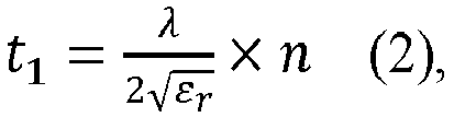
radar 5, εr is relative permittivity of the concealingpart 6a, and n is a positive integer. - If the thickness t 1 of the concealing
part 6 follows the above equation (2), the reflected electromagnetic wave R2 reflected by onesurface 62a of the concealingpart 6a facing theradar 5 and the reflected electromagnetic wave R1 reflected by theother surface 63a of the concealingpart 6a on a side opposite to the onesurface 62a weaken each other. Specifically, since a phase difference Δθ between the reflected electromagnetic waves R2 and R1 is (2m + 1) π (where m is a non-negative integer), the reflected electromagnetic waves R1 and R2 weaken each other. As a result, it is possible to reduce a reflectance of the concealingpart 6a to an electromagnetic wave emitted from theradar 5. Therefore, since intensity of a reflected electromagnetic wave reflected by the concealingpart 6a becomes weak, it is possible to prevent a reflected electromagnetic wave received by theradar 5 from affecting radar data as noise. For example, when the wavelength λ of the electromagnetic wave of theradar 5 is 3.922 mm, the relative permittivity εr of the concealingpart 6a is 2, and n = 1, the thickness t 1 of the concealingpart 6a is 1.386 mm. - Next, the
right radar module 17R will be specifically described with reference mainly toFIG. 22. FIG. 22 is a cross sectional view showing theright radar module 17R in the horizontal direction. As shown inFIG. 22 , thesupport member 8a is fixed to thelamp housing 14a with thescrews 22 as fixing units. That is, thesupport member 8a is fixed to theright vehicle lamp 302R with thescrews 22. Theradar 5 is supported and fixed by thelance 23 provided in thesupport member 8a. Theradar 5 includes: thefront surface 51; therear surface 52 on the side opposite to thefront surface 51; and the side surfaces 55 between thefront surface 51 and therear surface 52. An electromagnetic wave emitted from the antenna part 53 (transmission antenna) of theradar 5 are sent out into air via thefront surface 51. A reflected electromagnetic wave reflected by an object outside thevehicle 1C enters the antenna part 53 (receiving antenna) via thefront surface 51. - The
spacers rear surface 52 of theradar 5 and thesupport member 8. Thermal conductivity of thespacers support member 8a. Thespacer 20a touches therear surface 52 and theside surface 55 of theradar 5 and extends in the up-down direction along the side surfaces 55 of theradar 5. Similarly, thespacer 20b touches therear surface 52 and theside surface 55 of theradar 5 and extends in the up-down direction along the side surfaces 55 of theradar 5. Thespacer 20a faces thespacer 20b in the left-right direction across anair layer 30 - In this way, since the two
spacers radar 5 and thesupport member 8a, the air layer 30 (an example of a thermal insulation layer) can be relatively easily provided between therear surface 52 of theradar 5 and thesupport member 8a. - According to the present embodiment, since the
air layer 30 functioning as a thermal insulation layer is provided between thesupport member 8a and therear surface 52 of theradar 5, heat radiated from the engine (external heat source) behind theradar 5 is less transferred to therear surface 52 of theradar 5 via thesupport member 8a. In this way, it is possible to suitably prevent operation performance of the radar 5 (particularly, communication circuit part 54) from declining due to the heat radiated from the engine. Therefore, it is possible to conceal theradar 5 from the outside of thevehicle 1C with reliability of theradar 5 to heat radiated from the outside ensured. - If the
spacers radar 5 and thesupport member 8a, therear surface 52 of theradar 5 directly touches thesupport member 8a. In this case, heat radiated from the engine is easily transferred from thesupport member 8a having a high thermal conductivity to therear surface 52 of theradar 5, thereby the operation performance of theradar 5 significantly declining due to the heat radiated from the engine. - If the thermal conductivity of the
spacers support member 8a, heat radiated from the engine is less transferred to theradar 5 via thesupport member 8a. Therefore, thespacers support member 8a, which is made of a metal member. - Next,
positioning parts 39a to 39d (an example of a third positioning part) will be described below with reference toFIGS. 22 and23. FIG. 23 is a front view showing thepositioning parts 39a to 39d, theradar 5, and the concealingpart 6a. As shown inFIGS. 22 and23 , each of thepositioning parts 39a to 39d is integrally formed with the concealingpart 6a and is fixed to thesupport member 8a with thescrew 125 to position thesupport member 8a to the concealingpart 6a. In other words, the relative position between theradar 5 and the concealingpart 6a is determined by thepositioning parts 39a to 39d. - Each of the
positioning parts 39a to 39d is between the concealingpart 6a and thesupport member 8a in the front-rear direction. Thepositioning parts 39a to 39d may be formed of the same material (for example, an opaque resin material) as the concealingpart 6a. For example, the concealingpart 6a and thepositioning parts 39a to 39d may be integrally formed by injection molding using a mold - As shown in
FIG. 23 , thepositioning part 39a faces thepositioning part 39b in the left-right direction. Theradar 5 is between thepositioning part 39a and thepositioning part 39b in the left-right direction. Thepositioning part 39c faces thepositioning part 39a in the up-down direction. Thepositioning part 39d faces thepositioning part 39b in the up-down direction and faces thepositioning part 39c in the left-right direction. - Although the
support member 8a is positioned to the concealingpart 6a by the fourpositioning parts 39a to 39d in the present embodiment, the number of positioning parts is not limited to four. For example, the number of positioning parts may be two. In this case, it is preferable that one of the two positioning parts face the other positioning part across theradar 5 in the left-right direction. Further, the two positioning parts may extend in the up-down direction. By providing two or more positioning parts, thesupport member 8 can be positioned to the concealingpart 6a reliably. - According to the present embodiment, the
support member 8a is positioned to the concealingpart 6a by thepositioning parts 39a to 39d. Theradar 5 is supported and fixed by thesupport member 8a. In this way, since theradar 5 is positioned by thesupport member 8a, the relative position between thesupport member 8a and the concealingpart 6a is determined in accordance with the relative position between theradar 5 and the concealingpart 6a. - In the present embodiment, as shown in
FIG. 19 , theright radar module 17R is reliably positioned to theright vehicle lamp 302R by both the positioning part 65 in the concealingpart 6a and thepositioning part 80a in thesupport member 8a. In this way, theright radar module 17R can be positioned to theright vehicle lamp 302R by the twopositioning parts 65 and 80a. If theright vehicle lamp 302R has been positioned to thevehicle 1C, theradar 5 is positioned to thevehicle 1C when theright radar module 17R is positioned to theright vehicle lamp 302R. That is, theradar 5 is mounted on thevehicle 1C according to the following processes: - 1) a process for assembling the
right radar module 17R (theradar 5 is positioned to theright radar module 17R); - 2) a process for attaching the
right radar module 17R to theright vehicle lamp 302R (theradar 5 is positioned to theright vehicle lamp 302R); and - 3) a process for attaching the
right vehicle lamp 302R to thevehicle 1C (theradar 5 is positioned to thevehicle 1C). - Therefore, it is possible to provide the
right radar module 17R capable of concealing theradar 5 from the outside of thevehicle 1C and relatively easy and reliable positioning of theradar 5 to thevehicle 1C. - The
support member 8a is fixed to thelamp housing 14a with theright radar module 17R positioned to theright vehicle lamp 302R by thepositioning parts 65 and 80a. Therefore, theright radar module 17R is fixed to theright vehicle lamp 302R with theright radar module 17R reliably positioned to theright vehicle lamp 302R. - Although the
right radar module 17R is positioned to theright vehicle lamp 302R by the twopositioning parts 65 and 80a, the present embodiment is not limited thereto. For example, the positioning part may be provided only in one of the concealingpart 6a and thesupport member 8a. In this case, theright radar module 17R can be positioned to theright vehicle lamp 302R by only one of the twopositioning parts 65 and 80a. For example, thepositioning part 80a and thegroove 142 may be formed in a shape of a cross in a top view. In this case, by engaging thepositioning part 80a with thegroove 142, it is possible to position theright radar module 17R to theright vehicle lamp 302R reliably. - Although embodiments of the present invention have been described above, it goes without saying that the technical scope of the present invention should not be interpreted limitedly to the description of the embodiments. It is to be understood by those skilled in the art that the embodiments are mere examples and various modifications may be made within the scope of the invention described in the claims. The technical scope of the present invention should be determined based on the scope of the invention described in the claims and equivalents thereof.
- The present application incorporates the contents disclosed in Japanese Patent Applications (
Japanese Patent Application No. 2019-132826) filed on July 18, 2019 - Patent Application No.
2019-135290) filed on July 23, 2019 Japanese Patent Application No. 2019-138204) filed on July 26, 2019 Japanese Patent Application No. 2019-138205) filed on July 26, 2019 Japanese Patent Application No. 2019-138206) filed on July 26, 2019
Claims (37)
- A vehicle lamp comprising:a lamp housing;a lamp cover covering an opening of the lamp housing;an illumination unit disposed in a lamp chamber formed by the lamp housing and the lamp cover;a radar configured to acquire radar data indicating surroundings of a vehicle by emitting an electromagnetic wave outside the vehicle; anda concealing part that faces the radar to conceal the radar from the outside of the vehicle and is configured to let the electromagnetic wave emitted from the radar through, whereinthe concealing part is formed integrally with the lamp cover, anda boundary between the concealing part and the lamp cover is out of a field of view of the radar.
- The vehicle lamp according to claim 1, wherein
the radar is outside the lamp chamber. - The vehicle lamp according to claim 1, wherein
the radar is inside the lamp chamber. - The vehicle lamp according to any one of claims 1 to 3, wherein
a thickness t of the concealing part follows the following equation:
- The vehicle lamp according to any one of claims 1 to 4, wherein
a distance between the concealing part and the radar is not smaller than 20 mm and not greater than 100 mm. - The vehicle lamp according to any one of claims 1 to 5, wherein
the boundary is within a margin angular region adjacent to the field of view of the radar. - A vehicle lamp comprising:a lamp housing;a lamp cover covering an opening of the lamp housing;an illumination unit disposed in a lamp chamber formed by the lamp housing and the lamp cover;a radar configured to acquire radar data indicating surroundings of a vehicle by emitting an electromagnetic wave outside the vehicle;a concealing part that faces the radar to conceal the radar from the outside of the vehicle and is configured to let the electromagnetic wave emitted from the radar through; anda support member configured to support the radar, whereinthe radar includes: a front surface; and a rear surface on a side opposite to the front surface, anda thermal insulation layer having a thermal conductivity lower than the support member is provided between the support member and the rear surface of the radar.
- The vehicle lamp according to claim 7, wherein
the thermal insulation layer is an air layer. - The vehicle lamp according to claim 7 or 8, whereinthe concealing part is formed integrally with the lamp cover, andthe radar is outside the lamp chamber.
- The vehicle lamp according to any one of claims 7 to 9, further comprising:
a spacer provided between the rear surface of the radar and the support member. - The vehicle lamp according to claim 10, wherein
the spacer includes:a first spacer; anda second spacer that faces the first spacer in a first direction across the thermal insulation layer. - The vehicle lamp according to claim 11, wherein
the spacer further includes:a third spacer that faces the first spacer in a second direction perpendicular to the first direction across the thermal insulation layer; anda fourth spacer that faces the third spacer in the first direction across the thermal insulation layer and faces the second spacer in the second direction across the thermal insulation layer. - The vehicle lamp according to any one of claims 7 to 9, whereinthe support member includes:a front surface directly touches the rear surface of the radar;a rear surface on a side opposite to the front surface of the support member; anda convex that protrudes from the rear surface of the support member and faces the rear surface of the radar, andthe thermal insulation layer is between the convex and the rear surface of the radar.
- The vehicle lamp according to any one of claims 7 to 13, wherein
a thickness t of the concealing part follows the following equation:
- The vehicle lamp according to any one of claims 7 to 14, wherein
a distance between the concealing part and the radar is not smaller than 20 mm and not greater than 100 mm. - A vehicle lamp comprising:a lamp housing;a lamp cover covering an opening of the lamp housing;an illumination unit disposed in a lamp chamber formed by the lamp housing and the lamp cover;a radar configured to acquire radar data indicating surroundings of a vehicle by emitting an electromagnetic wave outside the vehicle;a concealing part that faces the radar to conceal the radar from the outside of the vehicle and is configured to let the electromagnetic wave emitted from the radar through; andan electromagnetic-wave absorption cover surrounding an antenna part of the radar to absorb the electromagnetic wave emitted from the radar.
- The vehicle lamp according to claim 16, wherein
the electromagnetic-wave absorption cover is out of a field of view of the radar. - The vehicle lamp according to claim 16 or 17, wherein
the electromagnetic-wave absorption cover is between the concealing part and the radar to be concealed from the outside of the vehicle by the concealing part. - The vehicle lamp according to any one of claims 16 to 18, further comprising:a support member that is fixed to the lamp housing and is configured to support the radar, wherein
the electromagnetic-wave absorption cover is fixed to the support member. - The vehicle lamp according to any one of claims 16 to 19, wherein
the concealing part is formed integrally with the lamp cover. - The vehicle lamp according to any one of claims 16 to 20, wherein
a thickness t of the concealing part follows the following equation:
- The vehicle lamp according to any one of claims 16 to 21, wherein
a distance between the concealing part and the radar is not smaller than 20 mm and not greater than 100 mm. - A vehicle lamp comprising:a lamp housing;a lamp cover covering an opening of the lamp housing;an illumination unit disposed in a lamp chamber formed by the lamp housing and the lamp cover;a radar configured to acquire radar data indicating surroundings of a vehicle by emitting an electromagnetic wave outside the vehicle;a concealing part that faces the radar to conceal the radar from the outside of the vehicle and is configured to let the electromagnetic wave emitted from the radar through; anda positioning part configured to touch the radar to position the radar to the concealing part, whereinthe concealing part is formed integrally with the lamp cover, andthe positioning part is formed integrally with the concealing part and is between the concealing part and the radar.
- The vehicle lamp according to claim 23, whereinthe radar includes:a front surface;a rear surface on a side opposite to the front surface; anda side surface between the front surface and the rear surface, andthe positioning part includes a concave configured to touch the front surface and the side surface of the radar.
- The vehicle lamp according to claim 23 or 24, whereinthe positioning part includes:a first positioning part; anda second positioning part that faces the first positioning part, andthe radar is between the first positioning part and the second positioning part.
- A vehicle lamp comprising:a lamp housing;a lamp cover covering an opening of the lamp housing;an illumination unit disposed in a lamp chamber formed by the lamp housing and the lamp cover;a radar configured to acquire radar data indicating surroundings of a vehicle by emitting an electromagnetic wave outside the vehicle;a concealing part that faces the radar to conceal the radar from the outside of the vehicle and is configured to let the electromagnetic wave emitted from the radar through;a support member configured to support and fix the radar; anda positioning part configured to touch the support member to position the support member to the concealing part, whereinthe concealing part is formed integrally with the lamp cover, andthe positioning part is formed integrally with the concealing part and is between the concealing part and the support member.
- The vehicle lamp according to any one of claims 23 to 26, wherein
the radar is outside the lamp chamber. - The vehicle lamp according to any one of claims 23 to 27, wherein
a thickness t of the concealing part follows the following equation:
- The vehicle lamp according to any one of claims 23 to 28, wherein
a distance between the concealing part and the radar is not smaller than 20 mm and not greater than 100 mm. - A vehicle comprising:
the vehicle lamp according to any one of claims 1 to 29. - A radar module attachable to a vehicle lamp comprising:a radar configured to acquire radar data indicating surroundings of a vehicle by emitting an electromagnetic wave outside the vehicle;a concealing part that faces the radar to conceal the radar from the outside of the vehicle and is configured to let the electromagnetic wave emitted from the radar through; anda support member configured to support and fix the radar, whereinat least one of the concealing part and the support member includes a positioning part configured to position the radar module to the vehicle lamp.
- The radar module according to claim 31, whereinthe concealing part includes a first positioning part configured to position the radar module to the vehicle lamp, andthe support member includes a second positioning part configured to position the radar module to the vehicle lamp.
- The radar module according to claim 31 or 32, wherein
the support member is fixed to the vehicle lamp. - The radar module according to any one of claims 31 to 33, further comprising:
a third positioning part configured to position the support member to the concealing part, wherein
the third positioning part is formed integrally with the concealing part and is fixed to the support member. - The radar module according to any one of claims 31 to 34, wherein
a thickness t of the concealing part follows the following equation:
- The radar module according to any one of claims 31 to 35, wherein
a distance between the concealing part and the radar is not smaller than 20 mm and greater than 100 mm. - A vehicle comprising:a vehicle lamp including:a lamp housing;a lamp cover covering an opening of the lamp housing; andan illumination unit disposed in a lamp chamber formed by the lamp housing and the lamp cover, andthe radar module attachable to the vehicle lamp according to any one of claims 31 to 36.
Applications Claiming Priority (6)
| Application Number | Priority Date | Filing Date | Title |
|---|---|---|---|
| JP2019132826 | 2019-07-18 | ||
| JP2019135290 | 2019-07-23 | ||
| JP2019138206 | 2019-07-26 | ||
| JP2019138204 | 2019-07-26 | ||
| JP2019138205 | 2019-07-26 | ||
| PCT/JP2020/027938 WO2021010483A1 (en) | 2019-07-18 | 2020-07-17 | Vehicle lamp, radar module, and vehicle |
Publications (2)
| Publication Number | Publication Date |
|---|---|
| EP4001016A1 true EP4001016A1 (en) | 2022-05-25 |
| EP4001016A4 EP4001016A4 (en) | 2022-09-14 |
Family
ID=74209917
Family Applications (1)
| Application Number | Title | Priority Date | Filing Date |
|---|---|---|---|
| EP20840000.2A Withdrawn EP4001016A4 (en) | 2019-07-18 | 2020-07-17 | VEHICLE LAMP, RADAR MODULE AND VEHICLE |
Country Status (4)
| Country | Link |
|---|---|
| US (2) | US11873964B2 (en) |
| EP (1) | EP4001016A4 (en) |
| JP (2) | JP7488262B2 (en) |
| WO (1) | WO2021010483A1 (en) |
Families Citing this family (13)
| Publication number | Priority date | Publication date | Assignee | Title |
|---|---|---|---|---|
| US12055626B2 (en) * | 2019-08-05 | 2024-08-06 | Koito Manufacturing Co., Ltd. | Vehicle lamp and vehicle |
| EP4043909A1 (en) * | 2019-09-10 | 2022-08-17 | Koito Manufacturing Co., Ltd. | Vehicle light fitting, radar module, radar, and vehicle |
| JP2022188944A (en) * | 2021-06-10 | 2022-12-22 | スタンレー電気株式会社 | lamp device |
| JPWO2023003033A1 (en) * | 2021-07-21 | 2023-01-26 | ||
| KR20240049606A (en) * | 2021-09-03 | 2024-04-16 | 닛토덴코 가부시키가이샤 | electromagnetic wave shield |
| JP2023061263A (en) * | 2021-10-19 | 2023-05-01 | スタンレー電気株式会社 | lamp device |
| JP7470724B2 (en) * | 2022-02-21 | 2024-04-18 | 本田技研工業株式会社 | Mounting structure for object detection device on vehicle body |
| JP2023148204A (en) * | 2022-03-30 | 2023-10-13 | 豊田合成株式会社 | Vehicle exterior parts and electromagnetic radar systems |
| JP2024013320A (en) * | 2022-07-20 | 2024-02-01 | スタンレー電気株式会社 | Vehicle lights |
| CN121100081A (en) * | 2023-03-31 | 2025-12-09 | 印度摩托车国际有限公司 | Vehicle front radar integration |
| JP7709493B2 (en) * | 2023-07-28 | 2025-07-16 | 本田技研工業株式会社 | Vehicle lighting with detection device |
| DE102023124172A1 (en) * | 2023-09-07 | 2025-03-13 | Brose Fahrzeugteile Se & Co. Kommanditgesellschaft, Bamberg | Radar arrangement for a motor vehicle |
| JP2025114411A (en) * | 2024-01-24 | 2025-08-05 | スタンレー電気株式会社 | A reflex reflector and a lamp device equipped with the reflex reflector. |
Family Cites Families (32)
| Publication number | Priority date | Publication date | Assignee | Title |
|---|---|---|---|---|
| JP2002071788A (en) * | 2000-08-30 | 2002-03-12 | Toyota Motor Corp | Radar device mounting method and radar device |
| JP3759447B2 (en) * | 2001-12-04 | 2006-03-22 | 本田技研工業株式会社 | Axle adjustment device for automotive radar system |
| JP2003240838A (en) * | 2002-02-19 | 2003-08-27 | Mitsubishi Electric Corp | Perimeter monitoring device for vehicles |
| JP2004312696A (en) | 2003-03-24 | 2004-11-04 | Hitachi Ltd | Millimeter wave radar and manufacturing method thereof |
| GB2411521A (en) | 2004-02-27 | 2005-08-31 | Qinetiq Ltd | Fabrication method for micro-sensor device |
| JP4065268B2 (en) * | 2004-11-15 | 2008-03-19 | アンリツ株式会社 | Automotive antenna |
| JP4842161B2 (en) | 2007-01-31 | 2011-12-21 | 株式会社小糸製作所 | Vehicle lighting |
| JP4497190B2 (en) * | 2007-10-19 | 2010-07-07 | 株式会社デンソー | Radar device and holding member |
| JP2010010100A (en) | 2008-06-30 | 2010-01-14 | Koito Mfg Co Ltd | Vehicular lighting fixture |
| JP4865775B2 (en) | 2008-09-17 | 2012-02-01 | 本田技研工業株式会社 | Camera mounting structure |
| JP2010091301A (en) * | 2008-10-03 | 2010-04-22 | Toyota Motor Corp | Radar equipment |
| JP5285405B2 (en) | 2008-12-02 | 2013-09-11 | 株式会社小糸製作所 | Vehicle lighting |
| JP2010154182A (en) * | 2008-12-25 | 2010-07-08 | Koito Mfg Co Ltd | On-vehicle radar apparatus |
| DE102011115952A1 (en) * | 2011-10-13 | 2013-04-18 | Conti Temic Microelectronic Gmbh | Radar device for use in e.g. bumper of vehicle for acquisition of traffic space in front of vehicle, has transmitting- or receiving unit receiving signal, where radar device is arranged behind reflector cover of vehicle |
| DE102011115829A1 (en) | 2011-10-13 | 2013-04-18 | Conti Temic Microelectronic Gmbh | Radar apparatus for vehicle e.g. motor car, has transmitting-receiving units for emitting radar beam as transmission signal, and receiving signal of target object within radiation area such that the radar beam is reflected |
| JP6131520B2 (en) | 2012-02-06 | 2017-05-24 | 三菱マテリアル株式会社 | Infrared sensor device |
| DE102012017669A1 (en) * | 2012-09-07 | 2014-03-13 | Valeo Schalter Und Sensoren Gmbh | Arrangement with a trim part and a radar sensor, motor vehicle and method for producing an arrangement |
| JP2015076352A (en) | 2013-10-11 | 2015-04-20 | パナソニックIpマネジメント株式会社 | Headlight unit |
| DE102013021819A1 (en) | 2013-12-21 | 2015-06-25 | Valeo Schalter Und Sensoren Gmbh | Radar device with a vehicle lamp and a radar sensor and motor vehicle with a radar device |
| GB201419861D0 (en) * | 2014-11-07 | 2014-12-24 | Trw Ltd | Mount |
| JP6510439B2 (en) * | 2016-02-23 | 2019-05-08 | 株式会社Soken | Antenna device |
| JP6786302B2 (en) | 2016-08-12 | 2020-11-18 | 株式会社小糸製作所 | Lighting device |
| JP2018112528A (en) * | 2017-01-13 | 2018-07-19 | 本田技研工業株式会社 | Cover member and sensor assembly |
| KR102384532B1 (en) | 2017-03-15 | 2022-04-08 | 삼성전자주식회사 | Electronic device having heat dissipation structure of camera |
| JP7139124B2 (en) | 2017-03-31 | 2022-09-20 | 三菱エンジニアリングプラスチックス株式会社 | Polycarbonate resin composition and molded article |
| US11333743B2 (en) | 2017-07-24 | 2022-05-17 | Koito Manufacturing Co., Ltd. | Lamp device, sensor system, and sensor device |
| JP6986718B2 (en) * | 2017-11-27 | 2021-12-22 | パナソニックIpマネジメント株式会社 | Antenna device |
| JP7046784B2 (en) | 2018-01-26 | 2022-04-04 | ヤンマーパワーテクノロジー株式会社 | Weight measurement system, weight sorting system |
| JP7010040B2 (en) | 2018-02-09 | 2022-01-26 | トヨタ自動車株式会社 | Engine control unit |
| JP6962225B2 (en) | 2018-02-09 | 2021-11-05 | マツダ株式会社 | Supercharged diesel engine |
| JP7119403B2 (en) | 2018-02-09 | 2022-08-17 | トヨタ自動車株式会社 | engine controller |
| DE102018008559A1 (en) | 2018-10-30 | 2019-03-28 | Daimler Ag | Radome for a radar sensor of a vehicle |
-
2020
- 2020-07-17 WO PCT/JP2020/027938 patent/WO2021010483A1/en not_active Ceased
- 2020-07-17 US US17/628,069 patent/US11873964B2/en active Active
- 2020-07-17 EP EP20840000.2A patent/EP4001016A4/en not_active Withdrawn
- 2020-07-17 JP JP2021533119A patent/JP7488262B2/en active Active
-
2023
- 2023-12-06 US US18/530,762 patent/US12222082B2/en active Active
-
2024
- 2024-05-09 JP JP2024076583A patent/JP7683082B2/en active Active
Also Published As
| Publication number | Publication date |
|---|---|
| JP2024109656A (en) | 2024-08-14 |
| WO2021010483A1 (en) | 2021-01-21 |
| JP7488262B2 (en) | 2024-05-21 |
| EP4001016A4 (en) | 2022-09-14 |
| JPWO2021010483A1 (en) | 2021-01-21 |
| US12222082B2 (en) | 2025-02-11 |
| US11873964B2 (en) | 2024-01-16 |
| JP7683082B2 (en) | 2025-05-26 |
| US20240110686A1 (en) | 2024-04-04 |
| US20220316678A1 (en) | 2022-10-06 |
Similar Documents
| Publication | Publication Date | Title |
|---|---|---|
| EP4001016A1 (en) | Vehicle lamp, radar module, and vehicle | |
| US12429582B2 (en) | Vehicle lamp and vehicle | |
| US6366245B1 (en) | Device for directionally emitting and/or receiving electromagnetic radiation | |
| US12269391B2 (en) | Vehicle light fitting, radar module, radar, and vehicle | |
| JP2020038181A (en) | Mounting structure of radar device | |
| CN212685403U (en) | Vehicle lamp and vehicle | |
| CN213542372U (en) | Vehicle lamp and vehicle | |
| CN212737941U (en) | Vehicle lamp and vehicle | |
| CN212980044U (en) | Radar module and vehicle | |
| JP2020051975A (en) | In-vehicle light device | |
| CN212737905U (en) | Vehicle lamp and vehicle | |
| WO2018043011A1 (en) | Vehicle-mounted antenna device | |
| CN212746304U (en) | Vehicle lamp and vehicle | |
| CN213649441U (en) | Vehicle lamp and vehicle | |
| CN212737906U (en) | Vehicle lamp and vehicle | |
| CN121004941A (en) | Vehicle-mounted radar device installation structure | |
| WO2023110558A1 (en) | Radar device arrangement for a vehicle and method to produce a radar device arrangement for a vehicle | |
| KR20250008313A (en) | Antenna apparatus and vehicl including the same | |
| CN118382966A (en) | Radar device for vehicle and method of manufacturing radar device for vehicle |
Legal Events
| Date | Code | Title | Description |
|---|---|---|---|
| STAA | Information on the status of an ep patent application or granted ep patent |
Free format text: STATUS: THE INTERNATIONAL PUBLICATION HAS BEEN MADE |
|
| PUAI | Public reference made under article 153(3) epc to a published international application that has entered the european phase |
Free format text: ORIGINAL CODE: 0009012 |
|
| STAA | Information on the status of an ep patent application or granted ep patent |
Free format text: STATUS: REQUEST FOR EXAMINATION WAS MADE |
|
| 17P | Request for examination filed |
Effective date: 20220117 |
|
| AK | Designated contracting states |
Kind code of ref document: A1 Designated state(s): AL AT BE BG CH CY CZ DE DK EE ES FI FR GB GR HR HU IE IS IT LI LT LU LV MC MK MT NL NO PL PT RO RS SE SI SK SM TR |
|
| A4 | Supplementary search report drawn up and despatched |
Effective date: 20220818 |
|
| RIC1 | Information provided on ipc code assigned before grant |
Ipc: G01S 13/931 20200101ALI20220811BHEP Ipc: F21W 102/14 20180101ALI20220811BHEP Ipc: F21W 102/13 20180101ALI20220811BHEP Ipc: F21W 102/00 20180101ALI20220811BHEP Ipc: F21S 45/00 20180101ALI20220811BHEP Ipc: F21S 43/20 20180101ALI20220811BHEP Ipc: F21S 41/20 20180101ALI20220811BHEP Ipc: F21S 41/00 20180101ALI20220811BHEP Ipc: B60R 11/02 20060101AFI20220811BHEP |
|
| DAV | Request for validation of the european patent (deleted) | ||
| DAX | Request for extension of the european patent (deleted) | ||
| STAA | Information on the status of an ep patent application or granted ep patent |
Free format text: STATUS: EXAMINATION IS IN PROGRESS |
|
| STAA | Information on the status of an ep patent application or granted ep patent |
Free format text: STATUS: THE APPLICATION HAS BEEN WITHDRAWN |
|
| 17Q | First examination report despatched |
Effective date: 20250320 |
|
| 18W | Application withdrawn |
Effective date: 20250415 |