EP4000998A2 - Bridge - Google Patents
Bridge Download PDFInfo
- Publication number
- EP4000998A2 EP4000998A2 EP21207693.9A EP21207693A EP4000998A2 EP 4000998 A2 EP4000998 A2 EP 4000998A2 EP 21207693 A EP21207693 A EP 21207693A EP 4000998 A2 EP4000998 A2 EP 4000998A2
- Authority
- EP
- European Patent Office
- Prior art keywords
- bridge
- connecting platform
- electrical connector
- abutting surface
- communication module
- Prior art date
- Legal status (The legal status is an assumption and is not a legal conclusion. Google has not performed a legal analysis and makes no representation as to the accuracy of the status listed.)
- Granted
Links
Images


Classifications
-
- H—ELECTRICITY
- H02—GENERATION; CONVERSION OR DISTRIBUTION OF ELECTRIC POWER
- H02J—ELECTRIC POWER NETWORKS; CIRCUIT ARRANGEMENTS OR SYSTEMS FOR SUPPLYING OR DISTRIBUTING ELECTRIC POWER; SYSTEMS FOR STORING ELECTRIC ENERGY
- H02J7/00—Circuit arrangements for charging or discharging batteries or for supplying loads from batteries
- H02J7/70—Circuit arrangements for charging or discharging batteries or for supplying loads from batteries characterised by the mechanical construction
-
- H—ELECTRICITY
- H01—ELECTRIC ELEMENTS
- H01R—ELECTRICALLY-CONDUCTIVE CONNECTIONS; STRUCTURAL ASSOCIATIONS OF A PLURALITY OF MUTUALLY-INSULATED ELECTRICAL CONNECTING ELEMENTS; COUPLING DEVICES; CURRENT COLLECTORS
- H01R13/00—Details of coupling devices of the kinds covered by groups H01R12/70 or H01R24/00 - H01R33/00
- H01R13/66—Structural association with built-in electrical component
- H01R13/665—Structural association with built-in electrical component with built-in electronic circuit
-
- B—PERFORMING OPERATIONS; TRANSPORTING
- B60—VEHICLES IN GENERAL
- B60L—PROPULSION OF ELECTRICALLY-PROPELLED VEHICLES; SUPPLYING ELECTRIC POWER FOR AUXILIARY EQUIPMENT OF ELECTRICALLY-PROPELLED VEHICLES; ELECTRODYNAMIC BRAKE SYSTEMS FOR VEHICLES IN GENERAL; MAGNETIC SUSPENSION OR LEVITATION FOR VEHICLES; MONITORING OPERATING VARIABLES OF ELECTRICALLY-PROPELLED VEHICLES; ELECTRIC SAFETY DEVICES FOR ELECTRICALLY-PROPELLED VEHICLES
- B60L53/00—Methods of charging batteries, specially adapted for electric vehicles; Charging stations or on-board charging equipment therefor; Exchange of energy storage elements in electric vehicles
- B60L53/60—Monitoring or controlling charging stations
- B60L53/65—Monitoring or controlling charging stations involving identification of vehicles or their battery types
-
- H—ELECTRICITY
- H01—ELECTRIC ELEMENTS
- H01M—PROCESSES OR MEANS, e.g. BATTERIES, FOR THE DIRECT CONVERSION OF CHEMICAL ENERGY INTO ELECTRICAL ENERGY
- H01M10/00—Secondary cells; Manufacture thereof
- H01M10/42—Methods or arrangements for servicing or maintenance of secondary cells or secondary half-cells
- H01M10/425—Structural combination with electronic components, e.g. electronic circuits integrated to the outside of the casing
-
- H—ELECTRICITY
- H01—ELECTRIC ELEMENTS
- H01M—PROCESSES OR MEANS, e.g. BATTERIES, FOR THE DIRECT CONVERSION OF CHEMICAL ENERGY INTO ELECTRICAL ENERGY
- H01M50/00—Constructional details or processes of manufacture of the non-active parts of electrochemical cells other than fuel cells, e.g. hybrid cells
- H01M50/50—Current conducting connections for cells or batteries
-
- H—ELECTRICITY
- H01—ELECTRIC ELEMENTS
- H01R—ELECTRICALLY-CONDUCTIVE CONNECTIONS; STRUCTURAL ASSOCIATIONS OF A PLURALITY OF MUTUALLY-INSULATED ELECTRICAL CONNECTING ELEMENTS; COUPLING DEVICES; CURRENT COLLECTORS
- H01R13/00—Details of coupling devices of the kinds covered by groups H01R12/70 or H01R24/00 - H01R33/00
- H01R13/46—Bases; Cases
-
- H—ELECTRICITY
- H01—ELECTRIC ELEMENTS
- H01R—ELECTRICALLY-CONDUCTIVE CONNECTIONS; STRUCTURAL ASSOCIATIONS OF A PLURALITY OF MUTUALLY-INSULATED ELECTRICAL CONNECTING ELEMENTS; COUPLING DEVICES; CURRENT COLLECTORS
- H01R13/00—Details of coupling devices of the kinds covered by groups H01R12/70 or H01R24/00 - H01R33/00
- H01R13/66—Structural association with built-in electrical component
- H01R13/70—Structural association with built-in electrical component with built-in switch
- H01R13/703—Structural association with built-in electrical component with built-in switch operated by engagement or disengagement of coupling parts, e.g. dual-continuity coupling part
-
- H—ELECTRICITY
- H01—ELECTRIC ELEMENTS
- H01M—PROCESSES OR MEANS, e.g. BATTERIES, FOR THE DIRECT CONVERSION OF CHEMICAL ENERGY INTO ELECTRICAL ENERGY
- H01M10/00—Secondary cells; Manufacture thereof
- H01M10/42—Methods or arrangements for servicing or maintenance of secondary cells or secondary half-cells
- H01M10/425—Structural combination with electronic components, e.g. electronic circuits integrated to the outside of the casing
- H01M2010/4278—Systems for data transfer from batteries, e.g. transfer of battery parameters to a controller, data transferred between battery controller and main controller
-
- H—ELECTRICITY
- H01—ELECTRIC ELEMENTS
- H01R—ELECTRICALLY-CONDUCTIVE CONNECTIONS; STRUCTURAL ASSOCIATIONS OF A PLURALITY OF MUTUALLY-INSULATED ELECTRICAL CONNECTING ELEMENTS; COUPLING DEVICES; CURRENT COLLECTORS
- H01R2201/00—Connectors or connections adapted for particular applications
- H01R2201/26—Connectors or connections adapted for particular applications for vehicles
-
- H—ELECTRICITY
- H04—ELECTRIC COMMUNICATION TECHNIQUE
- H04B—TRANSMISSION
- H04B5/00—Near-field transmission systems, e.g. inductive or capacitive transmission systems
- H04B5/20—Near-field transmission systems, e.g. inductive or capacitive transmission systems characterised by the transmission technique; characterised by the transmission medium
-
- Y—GENERAL TAGGING OF NEW TECHNOLOGICAL DEVELOPMENTS; GENERAL TAGGING OF CROSS-SECTIONAL TECHNOLOGIES SPANNING OVER SEVERAL SECTIONS OF THE IPC; TECHNICAL SUBJECTS COVERED BY FORMER USPC CROSS-REFERENCE ART COLLECTIONS [XRACs] AND DIGESTS
- Y02—TECHNOLOGIES OR APPLICATIONS FOR MITIGATION OR ADAPTATION AGAINST CLIMATE CHANGE
- Y02T—CLIMATE CHANGE MITIGATION TECHNOLOGIES RELATED TO TRANSPORTATION
- Y02T10/00—Road transport of goods or passengers
- Y02T10/60—Other road transportation technologies with climate change mitigation effect
- Y02T10/70—Energy storage systems for electromobility, e.g. batteries
-
- Y—GENERAL TAGGING OF NEW TECHNOLOGICAL DEVELOPMENTS; GENERAL TAGGING OF CROSS-SECTIONAL TECHNOLOGIES SPANNING OVER SEVERAL SECTIONS OF THE IPC; TECHNICAL SUBJECTS COVERED BY FORMER USPC CROSS-REFERENCE ART COLLECTIONS [XRACs] AND DIGESTS
- Y02—TECHNOLOGIES OR APPLICATIONS FOR MITIGATION OR ADAPTATION AGAINST CLIMATE CHANGE
- Y02T—CLIMATE CHANGE MITIGATION TECHNOLOGIES RELATED TO TRANSPORTATION
- Y02T10/00—Road transport of goods or passengers
- Y02T10/60—Other road transportation technologies with climate change mitigation effect
- Y02T10/7072—Electromobility specific charging systems or methods for batteries, ultracapacitors, supercapacitors or double-layer capacitors
-
- Y—GENERAL TAGGING OF NEW TECHNOLOGICAL DEVELOPMENTS; GENERAL TAGGING OF CROSS-SECTIONAL TECHNOLOGIES SPANNING OVER SEVERAL SECTIONS OF THE IPC; TECHNICAL SUBJECTS COVERED BY FORMER USPC CROSS-REFERENCE ART COLLECTIONS [XRACs] AND DIGESTS
- Y02—TECHNOLOGIES OR APPLICATIONS FOR MITIGATION OR ADAPTATION AGAINST CLIMATE CHANGE
- Y02T—CLIMATE CHANGE MITIGATION TECHNOLOGIES RELATED TO TRANSPORTATION
- Y02T90/00—Enabling technologies or technologies with a potential or indirect contribution to GHG emissions mitigation
- Y02T90/10—Technologies relating to charging of electric vehicles
- Y02T90/12—Electric charging stations
-
- Y—GENERAL TAGGING OF NEW TECHNOLOGICAL DEVELOPMENTS; GENERAL TAGGING OF CROSS-SECTIONAL TECHNOLOGIES SPANNING OVER SEVERAL SECTIONS OF THE IPC; TECHNICAL SUBJECTS COVERED BY FORMER USPC CROSS-REFERENCE ART COLLECTIONS [XRACs] AND DIGESTS
- Y02—TECHNOLOGIES OR APPLICATIONS FOR MITIGATION OR ADAPTATION AGAINST CLIMATE CHANGE
- Y02T—CLIMATE CHANGE MITIGATION TECHNOLOGIES RELATED TO TRANSPORTATION
- Y02T90/00—Enabling technologies or technologies with a potential or indirect contribution to GHG emissions mitigation
- Y02T90/10—Technologies relating to charging of electric vehicles
- Y02T90/16—Information or communication technologies improving the operation of electric vehicles
- Y02T90/167—Systems integrating technologies related to power network operation and communication or information technologies for supporting the interoperability of electric or hybrid vehicles, i.e. smartgrids as interface for battery charging of electric vehicles [EV] or hybrid vehicles [HEV]
-
- Y—GENERAL TAGGING OF NEW TECHNOLOGICAL DEVELOPMENTS; GENERAL TAGGING OF CROSS-SECTIONAL TECHNOLOGIES SPANNING OVER SEVERAL SECTIONS OF THE IPC; TECHNICAL SUBJECTS COVERED BY FORMER USPC CROSS-REFERENCE ART COLLECTIONS [XRACs] AND DIGESTS
- Y04—INFORMATION OR COMMUNICATION TECHNOLOGIES HAVING AN IMPACT ON OTHER TECHNOLOGY AREAS
- Y04S—SYSTEMS INTEGRATING TECHNOLOGIES RELATED TO POWER NETWORK OPERATION, COMMUNICATION OR INFORMATION TECHNOLOGIES FOR IMPROVING THE ELECTRICAL POWER GENERATION, TRANSMISSION, DISTRIBUTION, MANAGEMENT OR USAGE, i.e. SMART GRIDS
- Y04S30/00—Systems supporting specific end-user applications in the sector of transportation
- Y04S30/10—Systems supporting the interoperability of electric or hybrid vehicles
- Y04S30/14—Details associated with the interoperability, e.g. vehicle recognition, authentication, identification or billing
Definitions
- the present disclosure relates to a bridge, and more particularly, to a bridge for connecting a battery.
- the conventional battery connection module usually includes a battery holder and a battery connector.
- the shape of the battery holder is usually designed to match a part of the battery to accommodate the part of the battery.
- the battery holder has a larger size, and the structural design of a vehicle, charger or charging station equipped with such a battery connection module is also limited by the appearance of the battery holder.
- An aspect of the disclosure is to provide a bridge that can efficiently solve the aforementioned problems.
- a bridge includes a connecting platform, an electrical connector, a wireless communication module, and a processing unit.
- the electrical connector is disposed on the connecting platform.
- the wireless communication module is disposed on the connecting platform and configured to receive a wireless signal.
- the processing unit is configured to: carry out a verification process on information included in the wireless signal; and allow the electrical connector to transmit power when the verification process on the information turned out to be true.
- the connecting platform has an abutting surface and a groove recessed from the abutting surface.
- the electrical connector protrudes from the abutting surface.
- the wireless communication module includes an antenna. The antenna is accommodated in the groove.
- the bridge further includes a protective cover.
- the protective cover covers the wireless communication module.
- the protective cover is flush with the abutting surface of the connecting platform.
- the antenna surrounds the electrical connector.
- the wireless communication module further includes a matching board.
- the matching board is connected to the antenna and configured to adjust a communication frequency of the antenna.
- the bridge further includes a connection detector.
- the connection detector is disposed on the connecting platform, and is configured to be triggered to generate a trigger signal and transmit the trigger signal to the processing unit.
- the processing unit is further configured to carry out the verification process on the information upon receiving the trigger signal.
- the connection detector includes a detecting switch and an elastic member.
- the detecting switch is disposed on the connecting platform.
- the elastic member covers the detecting switch.
- the detecting switch is configured to be triggered by a deformation of the elastic member caused by an outside force to generate the trigger signal.
- the connecting platform has an abutting surface.
- the electrical connector and the connection detector protrude from the abutting surface.
- the verification process includes at least one of following steps: determining whether a battery manufacturer data included in the information meets a predetermined list; determining whether a battery status/health data included in the information meets a battery status/health standard; determining whether a charging history data included in the information meets a standard for number of charging times; and determining whether a battery type data included in the information meets a subscription plan.
- the processing unit can carry out a verification process on the wireless signal received from an external battery by the wireless communication module, and only allow the electrical connector and the external battery to transmit power when the verification process on the information turned out to be true.
- the charging and discharging of the external battery can be managed and controlled, and the device (such as a vehicle, a charger, or a charging station) equipped with the bridge can be prevented from being damaged due to the poor and uncontrolled quality of unverified external batteries.
- the connecting platform is chosen for accommodating a part of the external battery in the bridge of the present disclosure. Therefore, the bridge has a smaller overall size, which can effectively reduce the restriction on the structural design of the device equipped with the bridge.
- Fig. 1 is a side view of a vehicle 100 according to an embodiment of the present disclosure.
- the vehicle 100 for example, a straddle-type vehicle
- the vehicle 100 includes a housing 110 and a bridge 200.
- the housing 110 has an accommodating space 111, and the bridge 200 is disposed in the accommodating space 111 of the housing 110.
- the accommodating space 111 serves as a battery compartment for accommodating external batteries, and the bridge 200 is configured to establish an electrical connection between the power system of the vehicle 100 and the battery pack.
- Fig. 2 is a perspective view of the bridge 200 according to an embodiment of the present disclosure.
- Fig. 3 is another perspective view of the bridge 200 in Fig. 2 , in which a protective cover 250 is separately displayed.
- the bridge 200 includes a connecting platform 210 and an electrical connector 220.
- the connecting platform 210 has an abutting surface 211.
- the abutting surface 211 is configured to abut against an external battery (not shown). In other words, the abutting surface 211 can be used as a support surface for the external battery.
- the electrical connector 220 is disposed on the connecting platform 210 and protrudes from the abutting surface 211 of the connecting platform 210. Therefore, when the external battery abuts against the abutting surface 211 of the connecting platform 210, the electrical connector 220 can be plugged into the external battery to be electrically connected.
- the bridge 200 of the present embodiment that replaces the conventional battery holder with the connecting platform 210 can have a smaller overall size, thereby effectively reducing the restriction on the structural design of the device equipped with the bridge 200.
- the bridge 200 further includes a wireless communication module 230.
- the wireless communication module 230 is disposed on the connecting platform 210.
- the connecting platform 210 further has a groove 212 recessed from the abutting surface 211.
- the wireless communication module 230 includes an antenna 231.
- the antenna 231 is accommodated in the groove 212.
- the wireless communication module 230 can receive the wireless signal (e.g., the wireless signal sent by a communication module installed on the external battery) through the antenna 231.
- the wireless communication module 230 may be an NFC (Near-field communication) card reader, which can read information of an NFC module installed on the external battery.
- NFC Near-field communication
- the antenna 231 is ring-shaped and surrounds the electrical connector 220.
- the groove 212 of the connecting platform 210 is also ring-shaped. In this way, no matter in which orientation the external battery is connected to the electrical connector 220, the communication module disposed on the external battery can be aligned with a part of the antenna 231 up and down, so that the signal strength of the wireless signal received from the communication module of the external battery by the antenna 231 can be ensured.
- the bridge 200 further includes a protective cover 250.
- the protective cover 250 covers the wireless communication module 230.
- the protective cover 250 covers the antenna 231 of the wireless communication module 230 and is ring-shaped, so as to fitly cover the opening of the groove 212 of the connecting platform 210. In this way, the antenna 231 of the wireless communication module 230 can be protected by the protective cover 250, thereby effectively preventing the antenna 231 from being worn by the external battery.
- a material of the protective cover 250 includes plastic, but the present disclosure is not limited in this regard.
- the protective cover 250 may be a piece of Mylar, but the disclosure is not limited in this regard.
- the protective cover 250 is flush with the abutting surface 211 of the connecting platform 210. With this configuration, the bridge 200 can abut against the external battery with the abutting surface 211 and the protective cover 250 at the same time, so as to improve stability when the external battery abuts against the bridge 200.
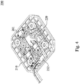
- Fig. 4 is another perspective view of the bridge 200 in Fig. 2 .
- the wireless communication module 230 further includes a matching board 232.
- the matching board 232 is connected to the antenna 231 and configured to adjust a communication frequency of the antenna through the operation of internal circuit, so as to make the wireless communication module 230 meet the predetermined factory standard.
- Fig. 5 is a functional block diagram of the bridge 200 according to an embodiment of the present disclosure.
- the bridge 200 further includes a processing unit 240.
- the processing unit 240 may be disposed at any position on the housing 110 and connected to the electrical connector 220 and the matching board 232 of the wireless communication module 230.
- the processing unit 240 is configured to carry out a verification process on information included in the wireless signal.
- the processing unit 240 is further configured to allow the electrical connector 220 to transmit power when the verification process on the information turned out to be true.
- the processing unit 240 is further configured to not allow the electrical connector 220 to transmit power when the verification process on the information turned out to be false.
- the processing unit 240 can carry out the verification process on the wireless signal received from the external battery by the wireless communication module 230, and only allow the electrical connector 220 to transmit power with the external battery when the verification process on the information turned out to be true. In this way, it is possible to prevent the device (such as the vehicle 100, a charger or a charging station) equipped with the bridge 200 from being damaged due to the poor quality of the unverified external battery.
- the verification process includes determining whether a battery manufacturer data included in the information meets a predetermined list.
- the predetermined list may include the provider of the vehicle 100. If the battery manufacturer data included in the information is consistent with the provider of the vehicle 100, the verification process turned out to be true.
- the verification process includes determining whether a battery status/health data included in the information meets a battery status/health standard. In some embodiments, the verification process includes determining whether a charging history data included in the information meets a standard for number of charging times. In some embodiments, the verification process includes determining whether a battery type data included in the information meets a subscription plan. It should be noted that the verification process is not limited to the above-mentioned embodiments.
- the bridge 200 further includes a connection detector 260.
- the connection detector 260 is disposed on the connecting platform 210, and is configured to be triggered to generate a trigger signal.
- the connection detector 260 protrudes from the abutting surface 211 to make the connection detector 260 generate the trigger signal when the external battery abuts against the abutting surface 211 of the connecting platform 210, the generation of the trigger signal can be used as an indication signal indicating that the bridge 200 is connected to the external battery.
- the connection detector 260 After the connection detector 260 generates the trigger signal, it will be sent to the processing unit 240.
- the processing unit 240 is further configured to carry out the verification process on the information of the wireless signal when receiving the trigger signal. In this way, the processing unit 240 can carry out the verification process only when the bridge 200 is connected to the external battery, thereby reducing the operating burden of the processing unit 240.
- the connection detector 260 includes a detecting switch 261 and an elastic member 262.
- the detecting switch 261 is disposed on the connecting platform 210.
- the elastic member 262 covers the detecting switch 261.
- the detecting switch 261 is configured to be triggered by the deformed elastic member 262 (e.g., pressed by the external battery) to generate the trigger signal.
- the detecting switch 261 is a contact switch and can generate the trigger signal when it receives a physical contact.
- the detecting switch 261 of the connection detector 260 may be a non-contact switch.
- the detecting switch 261 may be a reed switch, a photo-interrupter switch, etc., but the present disclosure is not limited in this regard.
- a material of the elastic member 262 includes rubber, but the present disclosure is not limited in this regard.
- any number of the bridges 200 can be connected in series, and these bridges 200 can share the same processing unit 240. Therefore, the bridge 200 of the present disclosure also has the feature of high scalability. In addition to being installed on electric vehicles, the bridge 200 can also be installed in any system that uses rechargeable batteries, such as charging stations, street lights, generators, uninterruptible power systems, power tools, and so on.
- the processing unit can carry out a verification process on the wireless signal received from an external battery by the wireless communication module, and only allow the electrical connector and the external battery to transmit power when the verification process on the information turned out to be true.
- the charging and discharging of the external battery can be managed and controlled, and the device (such as a vehicle, a charger, or a charging station) equipped with the bridge can be prevented from being damaged due to the poor and uncontrolled quality of unverified external batteries.
- the connecting platform is chosen for accommodating a part of the external battery in the bridge of the present disclosure. Therefore, the bridge has a smaller overall size, which can effectively reduce the restriction on the structural design of the device equipped with the bridge.
Landscapes
- Engineering & Computer Science (AREA)
- Microelectronics & Electronic Packaging (AREA)
- Chemical & Material Sciences (AREA)
- Chemical Kinetics & Catalysis (AREA)
- Electrochemistry (AREA)
- General Chemical & Material Sciences (AREA)
- Power Engineering (AREA)
- Manufacturing & Machinery (AREA)
- Transportation (AREA)
- Mechanical Engineering (AREA)
- Charge And Discharge Circuits For Batteries Or The Like (AREA)
- Arrangements For Transmission Of Measured Signals (AREA)
- Secondary Cells (AREA)
- Valve-Gear Or Valve Arrangements (AREA)
- Control Of Motors That Do Not Use Commutators (AREA)
- Stringed Musical Instruments (AREA)
Abstract
Description
- The present disclosure relates to a bridge, and more particularly, to a bridge for connecting a battery.
- With the proliferation of electric devices (such as power tools, appliances, personal portable communication devices, laptops and tablets, personal media devices, vehicles, etc.), people's interest in designing battery connection modules has also increased. The conventional battery connection module usually includes a battery holder and a battery connector. The shape of the battery holder is usually designed to match a part of the battery to accommodate the part of the battery. However, the battery holder has a larger size, and the structural design of a vehicle, charger or charging station equipped with such a battery connection module is also limited by the appearance of the battery holder.
- In addition, in general, power transmission between a vehicle, a charger or a charging station and a certified battery is a better operating scenario. If the vehicle, charger, or charging station is connected to a non-factory battery, it may be damaged due to the poor quality of the non-factory battery. As a result, the vehicle, charger or charging station may fail to operate normally.
- Accordingly, how to provide a bridge to solve the aforementioned problems becomes an important issue to be solved by those in the industry.
- An aspect of the disclosure is to provide a bridge that can efficiently solve the aforementioned problems.
- According to an embodiment of the disclosure, a bridge includes a connecting platform, an electrical connector, a wireless communication module, and a processing unit. The electrical connector is disposed on the connecting platform. The wireless communication module is disposed on the connecting platform and configured to receive a wireless signal. The processing unit is configured to: carry out a verification process on information included in the wireless signal; and allow the electrical connector to transmit power when the verification process on the information turned out to be true.
- In an embodiment of the disclosure, the connecting platform has an abutting surface and a groove recessed from the abutting surface. The electrical connector protrudes from the abutting surface. The wireless communication module includes an antenna. The antenna is accommodated in the groove.
- In an embodiment of the disclosure, the bridge further includes a protective cover. The protective cover covers the wireless communication module.
- In an embodiment of the disclosure, the protective cover is flush with the abutting surface of the connecting platform.
- In an embodiment of the disclosure, the antenna surrounds the electrical connector.
- In an embodiment of the disclosure, the wireless communication module further includes a matching board. The matching board is connected to the antenna and configured to adjust a communication frequency of the antenna.
- In an embodiment of the disclosure, the bridge further includes a connection detector. The connection detector is disposed on the connecting platform, and is configured to be triggered to generate a trigger signal and transmit the trigger signal to the processing unit. The processing unit is further configured to carry out the verification process on the information upon receiving the trigger signal.
- In an embodiment of the disclosure, the connection detector includes a detecting switch and an elastic member. The detecting switch is disposed on the connecting platform. The elastic member covers the detecting switch. The detecting switch is configured to be triggered by a deformation of the elastic member caused by an outside force to generate the trigger signal.
- In an embodiment of the disclosure, the connecting platform has an abutting surface. The electrical connector and the connection detector protrude from the abutting surface.
- In an embodiment of the disclosure, the verification process includes at least one of following steps: determining whether a battery manufacturer data included in the information meets a predetermined list; determining whether a battery status/health data included in the information meets a battery status/health standard; determining whether a charging history data included in the information meets a standard for number of charging times; and determining whether a battery type data included in the information meets a subscription plan.
- Accordingly, in the bridge of the present disclosure, the processing unit can carry out a verification process on the wireless signal received from an external battery by the wireless communication module, and only allow the electrical connector and the external battery to transmit power when the verification process on the information turned out to be true. In this way, the charging and discharging of the external battery can be managed and controlled, and the device (such as a vehicle, a charger, or a charging station) equipped with the bridge can be prevented from being damaged due to the poor and uncontrolled quality of unverified external batteries. In addition, instead of the conventional battery holder, the connecting platform is chosen for accommodating a part of the external battery in the bridge of the present disclosure. Therefore, the bridge has a smaller overall size, which can effectively reduce the restriction on the structural design of the device equipped with the bridge.
- It is to be understood that both the foregoing general description and the following detailed description are by examples, and are intended to provide further explanation of the disclosure as claimed.
- The disclosure can be more fully understood by reading the following detailed description of the embodiment, with reference made to the accompanying drawings as follows:
-
Fig. 1 is a side view of a vehicle according to an embodiment of the present disclosure; -
Fig. 2 is a perspective view of a bridge according to an embodiment of the present disclosure; -
Fig. 3 is another perspective view of the bridge inFig. 2 , in which a protective cover is separately displayed; -
Fig. 4 is another perspective view of the bridge inFig. 2 ; and -
Fig. 5 is a functional block diagram of the bridge according to an embodiment of the present disclosure. - Reference will now be made in detail to the present embodiments of the disclosure, examples of which are illustrated in the accompanying drawings. Wherever possible, the same reference numbers are used in the drawings and the description to refer to the same or like parts. However, specific structural and functional details disclosed herein are merely representative for purposes of describing example embodiments, and thus may be embodied in many alternate forms and should not be construed as limited to only example embodiments set forth herein. Therefore, it should be understood that there is no intent to limit example embodiments to the particular forms disclosed, but on the contrary, example embodiments are to cover all modifications, equivalents, and alternatives falling within the scope of the disclosure.
- Reference is made to
Fig. 1. Fig. 1 is a side view of avehicle 100 according to an embodiment of the present disclosure. As shown inFig. 1 , the vehicle 100 (for example, a straddle-type vehicle) includes ahousing 110 and abridge 200. Thehousing 110 has anaccommodating space 111, and thebridge 200 is disposed in theaccommodating space 111 of thehousing 110. In some embodiments, theaccommodating space 111 serves as a battery compartment for accommodating external batteries, and thebridge 200 is configured to establish an electrical connection between the power system of thevehicle 100 and the battery pack. - Reference is made to
Figs. 2 and3 .Fig. 2 is a perspective view of thebridge 200 according to an embodiment of the present disclosure.Fig. 3 is another perspective view of thebridge 200 inFig. 2 , in which aprotective cover 250 is separately displayed. As shown inFigs. 2 and3 , in the present disclosure, thebridge 200 includes a connectingplatform 210 and anelectrical connector 220. The connectingplatform 210 has anabutting surface 211. Theabutting surface 211 is configured to abut against an external battery (not shown). In other words, the abuttingsurface 211 can be used as a support surface for the external battery. Theelectrical connector 220 is disposed on the connectingplatform 210 and protrudes from the abuttingsurface 211 of the connectingplatform 210. Therefore, when the external battery abuts against the abuttingsurface 211 of the connectingplatform 210, theelectrical connector 220 can be plugged into the external battery to be electrically connected. - Compared with the conventional battery holder for accommodating a part of the external battery, the
bridge 200 of the present embodiment that replaces the conventional battery holder with the connectingplatform 210 can have a smaller overall size, thereby effectively reducing the restriction on the structural design of the device equipped with thebridge 200. - As shown in
Fig. 3 , in the present disclosure, thebridge 200 further includes awireless communication module 230. Thewireless communication module 230 is disposed on the connectingplatform 210. Specifically, the connectingplatform 210 further has agroove 212 recessed from the abuttingsurface 211. Thewireless communication module 230 includes anantenna 231. Theantenna 231 is accommodated in thegroove 212. In this way, thewireless communication module 230 can receive the wireless signal (e.g., the wireless signal sent by a communication module installed on the external battery) through theantenna 231. For example, thewireless communication module 230 may be an NFC (Near-field communication) card reader, which can read information of an NFC module installed on the external battery. - In some embodiments, the
antenna 231 is ring-shaped and surrounds theelectrical connector 220. Correspondingly, thegroove 212 of the connectingplatform 210 is also ring-shaped. In this way, no matter in which orientation the external battery is connected to theelectrical connector 220, the communication module disposed on the external battery can be aligned with a part of theantenna 231 up and down, so that the signal strength of the wireless signal received from the communication module of the external battery by theantenna 231 can be ensured. - As shown in
Fig. 3 , in the present disclosure, thebridge 200 further includes aprotective cover 250. Theprotective cover 250 covers thewireless communication module 230. Specifically, theprotective cover 250 covers theantenna 231 of thewireless communication module 230 and is ring-shaped, so as to fitly cover the opening of thegroove 212 of the connectingplatform 210. In this way, theantenna 231 of thewireless communication module 230 can be protected by theprotective cover 250, thereby effectively preventing theantenna 231 from being worn by the external battery. - In some embodiments, a material of the
protective cover 250 includes plastic, but the present disclosure is not limited in this regard. For example, theprotective cover 250 may be a piece of Mylar, but the disclosure is not limited in this regard. - In some embodiments, the
protective cover 250 is flush with theabutting surface 211 of the connectingplatform 210. With this configuration, thebridge 200 can abut against the external battery with theabutting surface 211 and theprotective cover 250 at the same time, so as to improve stability when the external battery abuts against thebridge 200. - Reference is made to
Fig. 4. Fig. 4 is another perspective view of thebridge 200 inFig. 2 . As shown inFigs. 3 and4 , in the present embodiment, thewireless communication module 230 further includes a matchingboard 232. The matchingboard 232 is connected to theantenna 231 and configured to adjust a communication frequency of the antenna through the operation of internal circuit, so as to make thewireless communication module 230 meet the predetermined factory standard. - Reference is made to
Fig. 5. Fig. 5 is a functional block diagram of thebridge 200 according to an embodiment of the present disclosure. As shown inFig. 5 , in the present embodiment, thebridge 200 further includes aprocessing unit 240. Theprocessing unit 240 may be disposed at any position on thehousing 110 and connected to theelectrical connector 220 and the matchingboard 232 of thewireless communication module 230. Theprocessing unit 240 is configured to carry out a verification process on information included in the wireless signal. Theprocessing unit 240 is further configured to allow theelectrical connector 220 to transmit power when the verification process on the information turned out to be true. On the contrary, theprocessing unit 240 is further configured to not allow theelectrical connector 220 to transmit power when the verification process on the information turned out to be false. - It can be seen that the
processing unit 240 can carry out the verification process on the wireless signal received from the external battery by thewireless communication module 230, and only allow theelectrical connector 220 to transmit power with the external battery when the verification process on the information turned out to be true. In this way, it is possible to prevent the device (such as thevehicle 100, a charger or a charging station) equipped with thebridge 200 from being damaged due to the poor quality of the unverified external battery. - In some embodiments, the verification process includes determining whether a battery manufacturer data included in the information meets a predetermined list. For example, the predetermined list may include the provider of the
vehicle 100. If the battery manufacturer data included in the information is consistent with the provider of thevehicle 100, the verification process turned out to be true. - In some embodiments, the verification process includes determining whether a battery status/health data included in the information meets a battery status/health standard. In some embodiments, the verification process includes determining whether a charging history data included in the information meets a standard for number of charging times. In some embodiments, the verification process includes determining whether a battery type data included in the information meets a subscription plan. It should be noted that the verification process is not limited to the above-mentioned embodiments.
- As shown in
Figs. 2 ,4 , and5 , in the present embodiment, thebridge 200 further includes aconnection detector 260. Theconnection detector 260 is disposed on the connectingplatform 210, and is configured to be triggered to generate a trigger signal. By designing the position of theconnection detector 260 on the connecting platform 210 (for example, theconnection detector 260 protrudes from the abutting surface 211) to make theconnection detector 260 generate the trigger signal when the external battery abuts against the abuttingsurface 211 of the connectingplatform 210, the generation of the trigger signal can be used as an indication signal indicating that thebridge 200 is connected to the external battery. After theconnection detector 260 generates the trigger signal, it will be sent to theprocessing unit 240. Theprocessing unit 240 is further configured to carry out the verification process on the information of the wireless signal when receiving the trigger signal. In this way, theprocessing unit 240 can carry out the verification process only when thebridge 200 is connected to the external battery, thereby reducing the operating burden of theprocessing unit 240. - As shown in
Figs. 2 and4 , in the present embodiment, theconnection detector 260 includes a detectingswitch 261 and anelastic member 262. The detectingswitch 261 is disposed on the connectingplatform 210. Theelastic member 262 covers the detectingswitch 261. The detectingswitch 261 is configured to be triggered by the deformed elastic member 262 (e.g., pressed by the external battery) to generate the trigger signal. In other words, the detectingswitch 261 is a contact switch and can generate the trigger signal when it receives a physical contact. - In some other embodiments, the detecting
switch 261 of theconnection detector 260 may be a non-contact switch. For example, the detectingswitch 261 may be a reed switch, a photo-interrupter switch, etc., but the present disclosure is not limited in this regard. - In some embodiments, a material of the
elastic member 262 includes rubber, but the present disclosure is not limited in this regard. - In some embodiments, any number of the
bridges 200 can be connected in series, and thesebridges 200 can share thesame processing unit 240. Therefore, thebridge 200 of the present disclosure also has the feature of high scalability. In addition to being installed on electric vehicles, thebridge 200 can also be installed in any system that uses rechargeable batteries, such as charging stations, street lights, generators, uninterruptible power systems, power tools, and so on. - According to the foregoing recitations of the embodiments of the disclosure, it can be seen that in the bridge of the present disclosure, the processing unit can carry out a verification process on the wireless signal received from an external battery by the wireless communication module, and only allow the electrical connector and the external battery to transmit power when the verification process on the information turned out to be true. In this way, the charging and discharging of the external battery can be managed and controlled, and the device (such as a vehicle, a charger, or a charging station) equipped with the bridge can be prevented from being damaged due to the poor and uncontrolled quality of unverified external batteries. In addition, instead of the conventional battery holder, the connecting platform is chosen for accommodating a part of the external battery in the bridge of the present disclosure. Therefore, the bridge has a smaller overall size, which can effectively reduce the restriction on the structural design of the device equipped with the bridge.
Claims (10)
- A bridge, comprising:a connecting platform;an electrical connector disposed on the connecting platform;a wireless communication module disposed on the connecting platform and configured to receive a wireless signal; anda processing unit configured to:carry out a verification process on information included in the wireless signal; andallow the electrical connector to transmit power when the verification process on the information turned out to be true.
- The bridge of claim 1, wherein the connecting platform has an abutting surface and a groove recessed from the abutting surface, the electrical connector protrudes from the abutting surface, the wireless communication module comprises an antenna, and the antenna is accommodated in the groove.
- The bridge of claim 1 or 2, further comprising a protective cover covering the wireless communication module.
- The bridge of claim 3, wherein the protective cover is flush with the abutting surface of the connecting platform.
- The bridge of claim 1 or 2, wherein the antenna surrounds the electrical connector.
- The bridge of claim 1 or 2, wherein the wireless communication module further comprises a matching board, and the matching board is connected to the antenna and configured to adjust a communication frequency of the antenna.
- The bridge of any preceding claim, further comprising a connection detector, the connection detector being disposed on the connecting platform, and being configured to be triggered to generate a trigger signal and transmit the trigger signal to the processing unit, wherein the processing unit is further configured to carry out the verification process on the information upon receiving the trigger signal.
- The bridge of claim 7, wherein the connection detector comprises:a detecting switch disposed on the connecting platform; andan elastic member covering the detecting switch,wherein the detecting switch is configured to be triggered by a deformation of the elastic member caused by an outside force to generate the trigger signal.
- The bridge of claim 7 or 8, wherein the connecting platform has an abutting surface, and the electrical connector and the connection detector protrude from the abutting surface.
- The bridge of any preceding claim, wherein the verification process comprises at least one of following steps:determining whether a battery manufacturer data included in the information meets a predetermined list;determining whether a battery status/health data included in the information meets a battery status/health standard;determining whether a charging history data included in the information meets a standard for number of charging times; anddetermining whether a battery type data included in the information meets a subscription plan.
Applications Claiming Priority (1)
| Application Number | Priority Date | Filing Date | Title |
|---|---|---|---|
| US202063112259P | 2020-11-11 | 2020-11-11 |
Publications (4)
| Publication Number | Publication Date |
|---|---|
| EP4000998A2 true EP4000998A2 (en) | 2022-05-25 |
| EP4000998A3 EP4000998A3 (en) | 2022-09-07 |
| EP4000998B1 EP4000998B1 (en) | 2024-10-23 |
| EP4000998C0 EP4000998C0 (en) | 2024-10-23 |
Family
ID=78621691
Family Applications (1)
| Application Number | Title | Priority Date | Filing Date |
|---|---|---|---|
| EP21207693.9A Active EP4000998B1 (en) | 2020-11-11 | 2021-11-11 | Bridge |
Country Status (7)
| Country | Link |
|---|---|
| US (1) | US12466284B2 (en) |
| EP (1) | EP4000998B1 (en) |
| JP (1) | JP7297033B2 (en) |
| CN (1) | CN114552302B (en) |
| ES (1) | ES2993500T3 (en) |
| PH (1) | PH12021050569A1 (en) |
| TW (1) | TWI789110B (en) |
Family Cites Families (32)
| Publication number | Priority date | Publication date | Assignee | Title |
|---|---|---|---|---|
| JP3625799B2 (en) * | 2001-11-30 | 2005-03-02 | 三洋電機株式会社 | Battery pack with authenticity detection circuit |
| JP2005285567A (en) | 2004-03-30 | 2005-10-13 | Casio Comput Co Ltd | Electronic device and battery unit used in the electronic device |
| JP5074490B2 (en) | 2007-06-13 | 2012-11-14 | 京セラ株式会社 | Charging system, portable electronic device, battery terminal used therefor, and secondary battery |
| JP4810564B2 (en) * | 2008-11-17 | 2011-11-09 | トヨタ自動車株式会社 | Charging cable for electric vehicle and management method thereof |
| JP2010187467A (en) * | 2009-02-12 | 2010-08-26 | Omron Corp | Battery charger for vehicle and method for controlling power supply port |
| US20100274570A1 (en) * | 2009-04-24 | 2010-10-28 | Gm Global Technology Operations, Inc. | Vehicle charging authorization |
| JP5644322B2 (en) * | 2010-09-28 | 2014-12-24 | 日産自動車株式会社 | Countermeasure device for inappropriate battery replacement of electric vehicle |
| US9058578B2 (en) * | 2010-12-24 | 2015-06-16 | Martin Kelly Jones | Systems and methods for battery remediation in connection with an electric powered mobiel thing (EPMT) |
| KR101768723B1 (en) * | 2011-03-30 | 2017-08-17 | 삼성전자주식회사 | Method and system for wireless charging in a portable terminal |
| CN103748765B (en) | 2011-06-14 | 2016-11-09 | 松下电器产业株式会社 | communication device |
| ES2692524T3 (en) * | 2011-07-26 | 2018-12-04 | Gogoro Inc. | Apparatus, method and article to provide vehicle diagnostic data |
| TWI517078B (en) * | 2011-07-26 | 2016-01-11 | 睿能創意公司 | Apparatus, method and article for a power storage device compartment |
| JP5498475B2 (en) * | 2011-12-27 | 2014-05-21 | 株式会社デンソー | Vehicle power line communication system |
| JP6074708B2 (en) * | 2013-03-12 | 2017-02-08 | パナソニックIpマネジメント株式会社 | Electric tool |
| JP6173057B2 (en) | 2013-06-11 | 2017-08-02 | キヤノン株式会社 | Power supply apparatus, power supply method, program, and recording medium |
| US9446674B2 (en) * | 2013-07-15 | 2016-09-20 | Qualcomm Incorporated | Systems, methods, and apparatus related to mutual detection and identification of electric vehicle and charging station |
| JP5958432B2 (en) * | 2013-07-23 | 2016-08-02 | トヨタ自動車株式会社 | vehicle |
| FR3027280B1 (en) * | 2014-10-20 | 2016-12-09 | Jcdecaux Sa | ELECTRIC MOTORIZATION CYCLE AND AUTOMATIC STORAGE SYSTEM OF SUCH CYCLES. |
| US9493083B1 (en) * | 2015-06-22 | 2016-11-15 | Delphi Technologies, Inc. | Electrical plug adapter |
| KR102390652B1 (en) * | 2017-05-18 | 2022-04-26 | 현대자동차주식회사 | Charging apparatus for vehicle |
| KR20190001077A (en) * | 2017-06-26 | 2019-01-04 | 엘지이노텍 주식회사 | Wireless Charging Apparatus and Method of Manufacturing the Same |
| CA3087315C (en) * | 2017-12-29 | 2024-04-16 | Shanghai Dianba New Energy Technology Co., Ltd. | Battery holder, power transfer device, electric vehicle and installation method for electric vehicle |
| TWI652877B (en) * | 2018-02-08 | 2019-03-01 | 大陸商雅迪科技集團有限公司 | Switching power supply identification system and charging method thereof |
| JP6903372B2 (en) * | 2018-03-20 | 2021-07-14 | 本田技研工業株式会社 | Management device |
| EP3859900B1 (en) * | 2018-09-27 | 2023-12-20 | Honda Motor Co., Ltd. | Male connector, and accommodating device comprising same |
| TWI745634B (en) * | 2018-11-09 | 2021-11-11 | 黃永昇 | Method and apparatus for controlling the electrical connection and disconnection between a battery unit and a supercapacitor on an automobile |
| US11001161B2 (en) * | 2019-02-15 | 2021-05-11 | Ford Global Technologies, Llc | Electric vehicle charging scheduler |
| EP4712306A3 (en) | 2019-03-27 | 2026-04-15 | Stryker Corporation | Autoclavable container for sterilizing a wirelessly chargeable battery |
| US10601176B1 (en) * | 2019-04-19 | 2020-03-24 | Gogoro Inc. | Connecting device and vehicle and charger using the same |
| WO2021021874A1 (en) * | 2019-07-30 | 2021-02-04 | Briggs & Stratton Corporation | Battery system and related management system |
| CN110492320A (en) * | 2019-08-15 | 2019-11-22 | 中航光电科技股份有限公司 | A kind of intelligence changes electrical interface connector |
| CN111427420B (en) * | 2020-03-24 | 2022-03-04 | 维沃移动通信有限公司 | A kind of electronic equipment control method and electronic equipment |
-
2021
- 2021-11-10 TW TW110141927A patent/TWI789110B/en active
- 2021-11-10 PH PH1/2021/050569A patent/PH12021050569A1/en unknown
- 2021-11-11 ES ES21207693T patent/ES2993500T3/en active Active
- 2021-11-11 JP JP2021184003A patent/JP7297033B2/en active Active
- 2021-11-11 CN CN202111333773.8A patent/CN114552302B/en active Active
- 2021-11-11 EP EP21207693.9A patent/EP4000998B1/en active Active
- 2021-11-11 US US17/523,992 patent/US12466284B2/en active Active
Also Published As
| Publication number | Publication date |
|---|---|
| EP4000998A3 (en) | 2022-09-07 |
| EP4000998B1 (en) | 2024-10-23 |
| CN114552302B (en) | 2025-03-18 |
| EP4000998C0 (en) | 2024-10-23 |
| TW202220310A (en) | 2022-05-16 |
| ES2993500T3 (en) | 2025-01-02 |
| US12466284B2 (en) | 2025-11-11 |
| JP7297033B2 (en) | 2023-06-23 |
| US20220149548A1 (en) | 2022-05-12 |
| JP2022077527A (en) | 2022-05-23 |
| PH12021050569A1 (en) | 2022-05-23 |
| CN114552302A (en) | 2022-05-27 |
| TWI789110B (en) | 2023-01-01 |
Similar Documents
| Publication | Publication Date | Title |
|---|---|---|
| US8116814B2 (en) | Mobile communications terminal using multi-functional socket and method thereof | |
| US8405363B2 (en) | Contact module for rechargeable battery, mobile electronic device having the same contact module and method of preventing rechargeable battery from exploding using the same contact module | |
| KR102795016B1 (en) | Electronic device comprising battery | |
| US9022267B2 (en) | Holder apparatus for a portable electronic device | |
| KR102934535B1 (en) | Battery and electronic device having the same | |
| US20130029192A1 (en) | Battery module and battery system | |
| US8016600B2 (en) | Electronic device and power adaptor and method for automatically disconnecting electronic device and power adaptor | |
| KR20200101225A (en) | Apparatus and method for providing user interface according to wireless power sharing | |
| TW201633041A (en) | Electronic component | |
| KR20160034578A (en) | Apparatus and method for wireless charging and vehicles with thereof | |
| US12466284B2 (en) | Bridge structure for vehicles and associated methods | |
| US20040183502A1 (en) | Rechargeable receiver | |
| EP2181470A1 (en) | Pass around electrical contacts | |
| US20160350579A1 (en) | Protection case for electronic device and fingerprint input method | |
| CN210516982U (en) | Antenna of electronic equipment and electronic equipment | |
| US20050178845A1 (en) | Contactless electronic communication device with optional auxiliary power source | |
| CN114614539B (en) | Power supply equipment and electronic equipment systems | |
| JP2021112001A (en) | Battery and portable terminal | |
| US9520912B1 (en) | Shock absorbing phone case with hidden compartment | |
| CN118646116B (en) | Battery protection circuit, battery protection board, electronic devices and control methods | |
| US20250046970A1 (en) | Electronic device including battery reset structure | |
| KR20250018905A (en) | Electronic device including battery reset structure | |
| WO2025029032A1 (en) | Electronic device including battery reset structure | |
| RU178828U1 (en) | Electronic tag | |
| JP2017213616A (en) | Information transmitter receiver |
Legal Events
| Date | Code | Title | Description |
|---|---|---|---|
| PUAI | Public reference made under article 153(3) epc to a published international application that has entered the european phase |
Free format text: ORIGINAL CODE: 0009012 |
|
| STAA | Information on the status of an ep patent application or granted ep patent |
Free format text: STATUS: REQUEST FOR EXAMINATION WAS MADE |
|
| 17P | Request for examination filed |
Effective date: 20211111 |
|
| AK | Designated contracting states |
Kind code of ref document: A2 Designated state(s): AL AT BE BG CH CY CZ DE DK EE ES FI FR GB GR HR HU IE IS IT LI LT LU LV MC MK MT NL NO PL PT RO RS SE SI SK SM TR |
|
| PUAL | Search report despatched |
Free format text: ORIGINAL CODE: 0009013 |
|
| STAA | Information on the status of an ep patent application or granted ep patent |
Free format text: STATUS: EXAMINATION IS IN PROGRESS |
|
| AK | Designated contracting states |
Kind code of ref document: A3 Designated state(s): AL AT BE BG CH CY CZ DE DK EE ES FI FR GB GR HR HU IE IS IT LI LT LU LV MC MK MT NL NO PL PT RO RS SE SI SK SM TR |
|
| RIC1 | Information provided on ipc code assigned before grant |
Ipc: H02J 7/00 20060101ALI20220801BHEP Ipc: H01M 50/20 20210101ALI20220801BHEP Ipc: B60L 53/65 20190101AFI20220801BHEP |
|
| 17Q | First examination report despatched |
Effective date: 20220818 |
|
| GRAP | Despatch of communication of intention to grant a patent |
Free format text: ORIGINAL CODE: EPIDOSNIGR1 |
|
| STAA | Information on the status of an ep patent application or granted ep patent |
Free format text: STATUS: GRANT OF PATENT IS INTENDED |
|
| INTG | Intention to grant announced |
Effective date: 20240717 |
|
| GRAS | Grant fee paid |
Free format text: ORIGINAL CODE: EPIDOSNIGR3 |
|
| GRAA | (expected) grant |
Free format text: ORIGINAL CODE: 0009210 |
|
| STAA | Information on the status of an ep patent application or granted ep patent |
Free format text: STATUS: THE PATENT HAS BEEN GRANTED |
|
| AK | Designated contracting states |
Kind code of ref document: B1 Designated state(s): AL AT BE BG CH CY CZ DE DK EE ES FI FR GB GR HR HU IE IS IT LI LT LU LV MC MK MT NL NO PL PT RO RS SE SI SK SM TR |
|
| REG | Reference to a national code |
Ref country code: GB Ref legal event code: FG4D |
|
| REG | Reference to a national code |
Ref country code: CH Ref legal event code: EP |
|
| REG | Reference to a national code |
Ref country code: DE Ref legal event code: R096 Ref document number: 602021020592 Country of ref document: DE |
|
| REG | Reference to a national code |
Ref country code: IE Ref legal event code: FG4D |
|
| U01 | Request for unitary effect filed |
Effective date: 20241023 |
|
| U07 | Unitary effect registered |
Designated state(s): AT BE BG DE DK EE FI FR IT LT LU LV MT NL PT RO SE SI Effective date: 20241106 |
|
| U20 | Renewal fee for the european patent with unitary effect paid |
Year of fee payment: 4 Effective date: 20241104 |
|
| REG | Reference to a national code |
Ref country code: ES Ref legal event code: FG2A Ref document number: 2993500 Country of ref document: ES Kind code of ref document: T3 Effective date: 20250102 |
|
| PG25 | Lapsed in a contracting state [announced via postgrant information from national office to epo] |
Ref country code: IS Free format text: LAPSE BECAUSE OF FAILURE TO SUBMIT A TRANSLATION OF THE DESCRIPTION OR TO PAY THE FEE WITHIN THE PRESCRIBED TIME-LIMIT Effective date: 20250223 Ref country code: HR Free format text: LAPSE BECAUSE OF FAILURE TO SUBMIT A TRANSLATION OF THE DESCRIPTION OR TO PAY THE FEE WITHIN THE PRESCRIBED TIME-LIMIT Effective date: 20241023 |
|
| PG25 | Lapsed in a contracting state [announced via postgrant information from national office to epo] |
Ref country code: NO Free format text: LAPSE BECAUSE OF FAILURE TO SUBMIT A TRANSLATION OF THE DESCRIPTION OR TO PAY THE FEE WITHIN THE PRESCRIBED TIME-LIMIT Effective date: 20250123 |
|
| PG25 | Lapsed in a contracting state [announced via postgrant information from national office to epo] |
Ref country code: GR Free format text: LAPSE BECAUSE OF FAILURE TO SUBMIT A TRANSLATION OF THE DESCRIPTION OR TO PAY THE FEE WITHIN THE PRESCRIBED TIME-LIMIT Effective date: 20250124 |
|
| PG25 | Lapsed in a contracting state [announced via postgrant information from national office to epo] |
Ref country code: PL Free format text: LAPSE BECAUSE OF FAILURE TO SUBMIT A TRANSLATION OF THE DESCRIPTION OR TO PAY THE FEE WITHIN THE PRESCRIBED TIME-LIMIT Effective date: 20241023 |
|
| PG25 | Lapsed in a contracting state [announced via postgrant information from national office to epo] |
Ref country code: RS Free format text: LAPSE BECAUSE OF FAILURE TO SUBMIT A TRANSLATION OF THE DESCRIPTION OR TO PAY THE FEE WITHIN THE PRESCRIBED TIME-LIMIT Effective date: 20250123 |
|
| REG | Reference to a national code |
Ref country code: CH Ref legal event code: PL |
|
| PG25 | Lapsed in a contracting state [announced via postgrant information from national office to epo] |
Ref country code: SM Free format text: LAPSE BECAUSE OF FAILURE TO SUBMIT A TRANSLATION OF THE DESCRIPTION OR TO PAY THE FEE WITHIN THE PRESCRIBED TIME-LIMIT Effective date: 20241023 |
|
| PG25 | Lapsed in a contracting state [announced via postgrant information from national office to epo] |
Ref country code: MC Free format text: LAPSE BECAUSE OF FAILURE TO SUBMIT A TRANSLATION OF THE DESCRIPTION OR TO PAY THE FEE WITHIN THE PRESCRIBED TIME-LIMIT Effective date: 20241023 |
|
| REG | Reference to a national code |
Ref country code: CH Ref legal event code: PL |
|
| PG25 | Lapsed in a contracting state [announced via postgrant information from national office to epo] |
Ref country code: CH Free format text: LAPSE BECAUSE OF NON-PAYMENT OF DUE FEES Effective date: 20241130 |
|
| PG25 | Lapsed in a contracting state [announced via postgrant information from national office to epo] |
Ref country code: SK Free format text: LAPSE BECAUSE OF FAILURE TO SUBMIT A TRANSLATION OF THE DESCRIPTION OR TO PAY THE FEE WITHIN THE PRESCRIBED TIME-LIMIT Effective date: 20241023 |
|
| PG25 | Lapsed in a contracting state [announced via postgrant information from national office to epo] |
Ref country code: CZ Free format text: LAPSE BECAUSE OF FAILURE TO SUBMIT A TRANSLATION OF THE DESCRIPTION OR TO PAY THE FEE WITHIN THE PRESCRIBED TIME-LIMIT Effective date: 20241023 |
|
| PLBE | No opposition filed within time limit |
Free format text: ORIGINAL CODE: 0009261 |
|
| STAA | Information on the status of an ep patent application or granted ep patent |
Free format text: STATUS: NO OPPOSITION FILED WITHIN TIME LIMIT |
|
| 26N | No opposition filed |
Effective date: 20250724 |
|
| PG25 | Lapsed in a contracting state [announced via postgrant information from national office to epo] |
Ref country code: IE Free format text: LAPSE BECAUSE OF NON-PAYMENT OF DUE FEES Effective date: 20241111 |
|
| U20 | Renewal fee for the european patent with unitary effect paid |
Year of fee payment: 5 Effective date: 20251126 |
|
| PGFP | Annual fee paid to national office [announced via postgrant information from national office to epo] |
Ref country code: ES Payment date: 20251201 Year of fee payment: 5 |
|
| PG25 | Lapsed in a contracting state [announced via postgrant information from national office to epo] |
Ref country code: HU Free format text: LAPSE BECAUSE OF FAILURE TO SUBMIT A TRANSLATION OF THE DESCRIPTION OR TO PAY THE FEE WITHIN THE PRESCRIBED TIME-LIMIT; INVALID AB INITIO Effective date: 20211111 |
|
| PG25 | Lapsed in a contracting state [announced via postgrant information from national office to epo] |
Ref country code: CY Free format text: LAPSE BECAUSE OF FAILURE TO SUBMIT A TRANSLATION OF THE DESCRIPTION OR TO PAY THE FEE WITHIN THE PRESCRIBED TIME-LIMIT; INVALID AB INITIO Effective date: 20211111 |