EP4000988A1 - Charging station comprising an inclination sensor having a conductive liquid - Google Patents
Charging station comprising an inclination sensor having a conductive liquid Download PDFInfo
- Publication number
- EP4000988A1 EP4000988A1 EP20208120.4A EP20208120A EP4000988A1 EP 4000988 A1 EP4000988 A1 EP 4000988A1 EP 20208120 A EP20208120 A EP 20208120A EP 4000988 A1 EP4000988 A1 EP 4000988A1
- Authority
- EP
- European Patent Office
- Prior art keywords
- sensor
- charging station
- conductive
- ring shaped
- contact
- Prior art date
- Legal status (The legal status is an assumption and is not a legal conclusion. Google has not performed a legal analysis and makes no representation as to the accuracy of the status listed.)
- Granted
Links
Images


Classifications
-
- B—PERFORMING OPERATIONS; TRANSPORTING
- B60—VEHICLES IN GENERAL
- B60L—PROPULSION OF ELECTRICALLY-PROPELLED VEHICLES; SUPPLYING ELECTRIC POWER FOR AUXILIARY EQUIPMENT OF ELECTRICALLY-PROPELLED VEHICLES; ELECTRODYNAMIC BRAKE SYSTEMS FOR VEHICLES IN GENERAL; MAGNETIC SUSPENSION OR LEVITATION FOR VEHICLES; MONITORING OPERATING VARIABLES OF ELECTRICALLY-PROPELLED VEHICLES; ELECTRIC SAFETY DEVICES FOR ELECTRICALLY-PROPELLED VEHICLES
- B60L53/00—Methods of charging batteries, specially adapted for electric vehicles; Charging stations or on-board charging equipment therefor; Exchange of energy storage elements in electric vehicles
- B60L53/10—Methods of charging batteries, specially adapted for electric vehicles; Charging stations or on-board charging equipment therefor; Exchange of energy storage elements in electric vehicles characterised by the energy transfer between the charging station and the vehicle
- B60L53/14—Conductive energy transfer
- B60L53/16—Connectors, e.g. plugs or sockets, specially adapted for charging electric vehicles
-
- B—PERFORMING OPERATIONS; TRANSPORTING
- B60—VEHICLES IN GENERAL
- B60L—PROPULSION OF ELECTRICALLY-PROPELLED VEHICLES; SUPPLYING ELECTRIC POWER FOR AUXILIARY EQUIPMENT OF ELECTRICALLY-PROPELLED VEHICLES; ELECTRODYNAMIC BRAKE SYSTEMS FOR VEHICLES IN GENERAL; MAGNETIC SUSPENSION OR LEVITATION FOR VEHICLES; MONITORING OPERATING VARIABLES OF ELECTRICALLY-PROPELLED VEHICLES; ELECTRIC SAFETY DEVICES FOR ELECTRICALLY-PROPELLED VEHICLES
- B60L53/00—Methods of charging batteries, specially adapted for electric vehicles; Charging stations or on-board charging equipment therefor; Exchange of energy storage elements in electric vehicles
- B60L53/30—Constructional details of charging stations
- B60L53/31—Charging columns specially adapted for electric vehicles
-
- B—PERFORMING OPERATIONS; TRANSPORTING
- B60—VEHICLES IN GENERAL
- B60L—PROPULSION OF ELECTRICALLY-PROPELLED VEHICLES; SUPPLYING ELECTRIC POWER FOR AUXILIARY EQUIPMENT OF ELECTRICALLY-PROPELLED VEHICLES; ELECTRODYNAMIC BRAKE SYSTEMS FOR VEHICLES IN GENERAL; MAGNETIC SUSPENSION OR LEVITATION FOR VEHICLES; MONITORING OPERATING VARIABLES OF ELECTRICALLY-PROPELLED VEHICLES; ELECTRIC SAFETY DEVICES FOR ELECTRICALLY-PROPELLED VEHICLES
- B60L53/00—Methods of charging batteries, specially adapted for electric vehicles; Charging stations or on-board charging equipment therefor; Exchange of energy storage elements in electric vehicles
- B60L53/60—Monitoring or controlling charging stations
-
- Y—GENERAL TAGGING OF NEW TECHNOLOGICAL DEVELOPMENTS; GENERAL TAGGING OF CROSS-SECTIONAL TECHNOLOGIES SPANNING OVER SEVERAL SECTIONS OF THE IPC; TECHNICAL SUBJECTS COVERED BY FORMER USPC CROSS-REFERENCE ART COLLECTIONS [XRACs] AND DIGESTS
- Y02—TECHNOLOGIES OR APPLICATIONS FOR MITIGATION OR ADAPTATION AGAINST CLIMATE CHANGE
- Y02T—CLIMATE CHANGE MITIGATION TECHNOLOGIES RELATED TO TRANSPORTATION
- Y02T10/00—Road transport of goods or passengers
- Y02T10/60—Other road transportation technologies with climate change mitigation effect
- Y02T10/70—Energy storage systems for electromobility, e.g. batteries
-
- Y—GENERAL TAGGING OF NEW TECHNOLOGICAL DEVELOPMENTS; GENERAL TAGGING OF CROSS-SECTIONAL TECHNOLOGIES SPANNING OVER SEVERAL SECTIONS OF THE IPC; TECHNICAL SUBJECTS COVERED BY FORMER USPC CROSS-REFERENCE ART COLLECTIONS [XRACs] AND DIGESTS
- Y02—TECHNOLOGIES OR APPLICATIONS FOR MITIGATION OR ADAPTATION AGAINST CLIMATE CHANGE
- Y02T—CLIMATE CHANGE MITIGATION TECHNOLOGIES RELATED TO TRANSPORTATION
- Y02T10/00—Road transport of goods or passengers
- Y02T10/60—Other road transportation technologies with climate change mitigation effect
- Y02T10/7072—Electromobility specific charging systems or methods for batteries, ultracapacitors, supercapacitors or double-layer capacitors
-
- Y—GENERAL TAGGING OF NEW TECHNOLOGICAL DEVELOPMENTS; GENERAL TAGGING OF CROSS-SECTIONAL TECHNOLOGIES SPANNING OVER SEVERAL SECTIONS OF THE IPC; TECHNICAL SUBJECTS COVERED BY FORMER USPC CROSS-REFERENCE ART COLLECTIONS [XRACs] AND DIGESTS
- Y02—TECHNOLOGIES OR APPLICATIONS FOR MITIGATION OR ADAPTATION AGAINST CLIMATE CHANGE
- Y02T—CLIMATE CHANGE MITIGATION TECHNOLOGIES RELATED TO TRANSPORTATION
- Y02T90/00—Enabling technologies or technologies with a potential or indirect contribution to GHG emissions mitigation
- Y02T90/10—Technologies relating to charging of electric vehicles
- Y02T90/12—Electric charging stations
-
- Y—GENERAL TAGGING OF NEW TECHNOLOGICAL DEVELOPMENTS; GENERAL TAGGING OF CROSS-SECTIONAL TECHNOLOGIES SPANNING OVER SEVERAL SECTIONS OF THE IPC; TECHNICAL SUBJECTS COVERED BY FORMER USPC CROSS-REFERENCE ART COLLECTIONS [XRACs] AND DIGESTS
- Y02—TECHNOLOGIES OR APPLICATIONS FOR MITIGATION OR ADAPTATION AGAINST CLIMATE CHANGE
- Y02T—CLIMATE CHANGE MITIGATION TECHNOLOGIES RELATED TO TRANSPORTATION
- Y02T90/00—Enabling technologies or technologies with a potential or indirect contribution to GHG emissions mitigation
- Y02T90/10—Technologies relating to charging of electric vehicles
- Y02T90/14—Plug-in electric vehicles
Definitions
- the present invention refers according to claim 1 to a charging station for charging electric vehicles and according to claim 15 to a method for charging electric vehicles.
- Document KR20120097107A discloses a tilt sensor that measures the inclination of a charging device due to external impact and outputs the measured result as a specific signal.
- a controller receives a sensor signal from the tilt sensor and controls the on and off of a switch according to the sensor signal.
- a switch switches on and off the connection of an electric vehicle according to a control signal of the controller.
- the charging pole comprises a main switch, a main contactor, a second contactor, a charging coupler, at least one sensor and a control unit.
- the sensor is used to detect acceleration and/or a tilt angle of the charging pole due to a transient outside force, for example a collision force caused by the EV driver's mis-operation.
- the control unit will instruct the main contactor to break the power contact of the charging coupler, so that the charging pole will be power-off.
- Document RU188167U1 discloses a tilt angle sensor inside the body of a charging station, which allows to control the position of the charging station and, in the event of a change in position caused by natural disasters or the onset of actions of third parties, the charging station goes into emergency mode, in which the controller turns off the power supply to avoid electric shock to a person, as well as sends an urgent emergency message to a remote central server to the operator-engineer.
- Document JP2010263666A discloses an electric vehicle charging station having a charging connection means for connecting a power supply source to an electric vehicle includes a circuit breaker for interrupting power supply from the power supply source to the charging connection means, and a control means for output of a circuit interruption signal to the circuit breaker, wherein the control means outputs the circuit interruption signal on the basis of the impact detection data of an impact sensor for sensing an impact to the charging station as an impact acceleration.
- Document CN109795349A discloses a charging pile system, that comprises a server, a plurality of charging piles connected with server signal and a plurality of maintenance interactive terminals connected with the server.
- Each charging pile comprises a main flow module, a fault self-detection module connected with the main flow module, a communication module connected with the fault detection module and a positioning module connected with the communication module;
- the main communication module is provided with an input end and an output end and includes an input protection module, and the input protection module is connected between the input end and the output end of the main flow module;
- the fault self-detection module detects the internal environment of the charging piles and generates fault detection signals;
- the input protection module generates protection action according to the fault detection signals;
- the communication module locates the pile positioning information of the modules according to the fault detection signals and generates maintenance request signals;
- the server sends maintenance assignment messages to the maintenance interactive terminals according to the maintenance request signals, maintenance efficiency of the charging piles is improved.
- a car charger has inputs and outputs which has high power.
- Some careless drivers may hit the charging station after the charge has run out or when approaching the charging station for charging. This can be very dangerous for the car and driver.
- the high current and voltage inputs and outputs in the charging station are located on the station.
- a problem with the system isolation as a result of impact may cause damage to the user or the car. In this case, it is a requirement for both the health of the driver and the safety of the car that the system detects the impact and activates the subsequent safety protocols.
- Said charging station is preferably a charging station for charging at least one electric vehicles, in particularly at least one electric car.
- Said charging station preferably comprises at least a housing, wherein the housing has a column like shape, in particularly a straight column.
- a power outlet is preferably arranged or attached at the outside of the housing, wherein the power outlet is at least indirectly, and preferably directly, connectable to an electric vehicle for charging the electric vehicle.
- At least an electric control unit, a sensor unit for sensing movements or the charging station and/or a power supply unit are preferably at least partially or completely arranged inside said housing.
- the electric control unit preferably controls power flow from the power supply unit to the power outlet.
- the sensor unit preferably provides sensor signal or sensor data representing an inclination and/or a direction of inclination, wherein the sensor unit preferably comprises a receiving space and a first - preferably ring shaped - sensor part, wherein the receiving space is at least partially filled with a conductive liquid, wherein the conductive liquid is preferably electrically coupled with a first contact.
- the first ring shaped sensor part preferably forms one conductive surface or a plurality of conductive surfaces or surface sections facing a center of the first ring shaped sensor part.
- Each conductive surface or surface section is preferably coupled with at least one second contact.
- the plurality of surfaces or surface sections is preferably spaced apart from the conductive liquid and wherein in the default configuration a longitudinal axis of the charging station matches with a vertical axis.
- the longitudinal axis of the charging station is preferably inclined in an angle above a predefined threshold with respect to the vertical axis.
- the conductive liquid preferably connects in the first inclined configuration the first contact and via at least one of the conductive surfaces or via at least one of the conductive surface sections at least the second contact or at least one second contact.
- the sensor unit preferably provides sensor signals or sensor data in dependency of the respective conductive surface or surface section which is/are in contact with the conductive liquid in the first inclined configuration, wherein the sensor signals or sensor data represent the inclination and/or the direction of inclination.
- the control unit preferably processes the sensor signals or sensor data and interrupts power supply in case the inclination represented by the sensor signal or sensor data is above a predefined inclination threshold and/or in case the direction of inclination represented by the sensor signal or sensor data represents a predefined direction of inclination.
- This solution is beneficial since an impact on a charging station, in particularly by a vehicle, can be detected in a reliable manner. Furthermore, inclination and/or orientation of the inclination can be detected.
- the conductive surfaces or surface sections are according to a further preferred embodiment of the present invention part of one or multiple elements, in particularly wall member/s or wall section/s, which differ in electric resistance from each other.
- This embodiment is beneficial since the individual elements can be designed with different shapes (E.g. thick, thin) or different materials (cupper, steal, iron, aluminum, ceramic) to set up differing conductivity properties.
- Each of the conductive surfaces or surface sections comprises according to a further preferred embodiment of the present invention a second contact, wherein the respective level of current and/or level of voltage per conductive surface or surface section differs from the level of current and/or level of voltage of the other conductive surfaces or surface sections.
- This embodiment is beneficial since each possible circuit comprises different current and/or voltage properties. Thus, in dependency of the measured or evaluated properties it can be determined in which direction the conductive liquid flowed.
- the center axis of the first ring shaped sensor part extends according to a further preferred embodiment of the present invention in the default configuration in parallel or coaxial to the vertical axis.
- This embodiment is beneficial since a distance between the receiving space and the first ring shaped part is preferably constant.
- the flow path of the conductive liquid for closing a circuit has preferably the same length (starting from a default position) for each of the circuits which might be set up between the first contact and any of the second contacts.
- the first ring shaped sensor part comprises according to a further preferred embodiment of the present invention at least four and preferably eight or sixteen conductive surfaces or surface sections, wherein said conductive surfaces or surface sections are electrically isolated from each other.
- This embodiment is beneficial since due to the isolation members cross-talking between two neighboring surfaces or surface sections can be avoided, thus the quality of the detected signals is enhanced.
- a second- preferably ring shaped - sensor part is arranged according to a further preferred embodiment of the present invention in coaxial manner above the first ring shaped sensor part, wherein the first ring shaped sensor part is arranged between the second ring shaped sensor part and the receiving space, wherein the second ring shaped sensor part comprises one conductive surface facing the center axis, wherein the conductive surface at least mainly and preferably completely extends along long a circumferential direction, wherein the conductive surface of the second ring shaped part is coupled with a third contact.
- This embodiment is beneficial since due to the plurality of sensor parts the inclination respectively a degree of inclination can be determined in a reliable manner.
- the conductive liquid contacts the second ring shaped sensor part it is clear that the inclination of the charging station must be larger compared to a situation in which the liquid only contacts the first ring shaped sensor part.
- the conductive liquid contacts one or at least one conductive surface or one or at least one conductive surface section of the first ring shaped sensor part and the conductive surface of the second ring shaped sensor part, wherein the sensor unit provides second sensor signals or second sensor data in case the conductive liquid also contacts the conductive surface of the second ring shaped sensor part, wherein the second sensor signals or second sensor data represents the inclination and/or the direction of inclination.
- a second ring shaped sensor part is arranged according to a further preferred embodiment of the present invention in coaxial manner above the first ring shaped sensor part, wherein the second ring shaped sensor part forms a plurality of conductive surfaces or surface sections facing a center of the second ring shaped sensor part, wherein each conductive surface or surface section is coupled with at least one third contact, wherein in a default configuration the plurality of surfaces or surface sections is spaced apart from the conductive liquid.
- the conductive liquid preferably contacts one or at least one conductive surface or one or at least one conductive surface section of the first ring shaped sensor part and preferably one or at least one conductive surface, in particularly of a plurality of conductive surfaces, or one or at least one conductive surface section, in particularly of a plurality of conductive surface sections, of the second ring shaped sensor part.
- the conductive liquid preferably connects in the second inclined configuration the first contact and via the conductive surface or surface section the at least second contact or at least one second contact of the first ring shaped part.
- the conductive liquid preferably connects in the second inclined configuration via the conductive surface or surface section of the second ring shaped part the one third contact or at least one third contact of the second ring shaped part.
- the sensor unit preferably provides sensor signals or sensor data in dependency of the respective conductive surface or surface section of the second ring shaped part which is/are in contact with the conductive liquid in the second inclined configuration, wherein the sensor signals or sensor data represent the inclination and/or the direction of inclination.
- the control unit preferably processes the sensor signals or sensor data and interrupts power supply in case the inclination represented by the sensor signal or sensor data is above a predefined inclination threshold and/or in case the direction of inclination represented by the sensor signal or sensor data represents a predefined direction of inclination.
- multiple sensor parts in particularly ring-shaped sensor parts, can comprise multiple conductive surfaces or surface sections.
- the inclination and/or orientation of inclination can be detected or evaluated in a more detailed manner in case multiple or each sensor part has several surfaces or surface section for closing circuits with different properties.
- a third - preferably ring shaped - sensor part is arranged according to a further preferred embodiment of the present invention in coaxial manner above the second ring shaped sensor part, wherein the second ring shaped sensor part is arranged between the first ring shaped sensor part and the third ring shaped sensor part, wherein the third ring shaped sensor part comprises one conductive surface facing the center axis, wherein the conductive surface at least mainly and preferably completely extends along long a circumferential direction, wherein the conductive surface of the third ring shaped part is preferably coupled with a fourth contact.
- This embodiment is beneficial since a larger range of inclination can be detected in case a third sensor part is part of the sensor unit.
- the conductive liquid contacts preferably one or at least one conductive surface or one or at least one conductive surface section of the first ring shaped sensor part and the conductive surface of the second ring shaped sensor part and the conductive surface of the third ring shaped sensor part.
- the sensor unit preferably provides third sensor signals or third sensor data in case the conductive liquid also contacts the conductive surface of the third ring shaped sensor part, wherein the third sensor signals or third sensor data represents the inclination and/or the direction of inclination.
- a third ring shaped sensor part is arranged according to a further preferred embodiment of the present invention in coaxial manner above the second ring shaped sensor part, wherein the third ring shaped sensor part preferably forms a plurality of conductive surfaces or surface sections facing a center of the third ring shaped sensor part, wherein each conductive surface or surface section is preferably coupled with at least one fourth contact, wherein in a default configuration the plurality of surfaces or surface sections is preferably spaced apart from the conductive liquid.
- the conductive liquid preferably contacts one or at least one conductive surface or one or at least one conductive surface section of the third ring shaped sensor part and one or at least one conductive surface or one or at least one conductive surface section of the second ring shaped sensor part and one or at least one conductive surface or one or at least one conductive surface section of the first ring shaped sensor part.
- the conductive liquid preferably connects in the third inclined configuration the first contact and via the conductive surface or surface section the at least second contact or at least one second contact of the first ring shaped part and wherein the conductive liquid preferably connects in the third inclined configuration via the conductive surface or surface section of the second ring shaped part the one third contact or at least one third contact of the second ring shaped part and wherein the conductive liquid connects in the third inclined configuration via the conductive surface or surface section of the third ring shaped part the one fourth contact or at least one fourth contact of the third ring shaped part.
- the sensor unit preferably provides sensor signals or sensor data in dependency of the respective conductive surface or surface section of the third ring shaped part which is/are in contact with the conductive liquid in the second inclined configuration, wherein the sensor signals or sensor data represent the inclination and/or the direction of inclination.
- the control unit preferably processes the sensor signals or sensor data and interrupts power supply in case the inclination represented by the sensor signal or sensor data is above a predefined inclination threshold and/or in case the direction of inclination represented by the sensor signal or sensor data represents a predefined direction of inclination.
- multiple sensor parts in particularly ring-shaped sensor parts, can comprise multiple conductive surfaces or surface sections.
- the inclination and/or orientation of inclination can be detected or evaluated in a more detailed manner in case multiple or each sensor part has several surfaces or surface section for closing circuits with different properties.
- the first contact is according to a further preferred embodiment of the present invention permanently biased with current and/or voltage.
- This embodiment is beneficial since power flow is established in case the conductive liquid contacts any of the conductive surfaces or surface sections.
- the properties of the power flow hereby preferably depend on the conductive surface or surface section the conductive liquid is flowing to in response to a tilting movement of the charging station.
- the second contact or each second contact is according to a further preferred embodiment of the present invention permanently biased with current and/or voltage and/or the third contact or each third contact is permanently biased with current and/or voltage, and/or the fourth contact or each fourth contact is permanently biased with current and/or voltage.
- each conductive surface or surface section is biased with a different current and/or voltage.
- each conductive surface or surface section of a sensor part is biased with a different current and/or voltage. It is possible that the two or multiple or the majority or all sensor parts are designed in an identical manner.
- This embodiment is beneficial since closing of a circuit is established in case the conductive liquid contacts any of the conductive surfaces or surface sections. Since the properties of the power flowing within said closed circuit are known it is known which conductive surface or surface section the conductive liquid contacts, thus it is known in which direction the inclination is oriented.
- An angle between the longitudinal axis of the charging station and a horizontal axis is according to a further preferred embodiment of the present invention smaller in the second inclined configuration compared to the first inclined configuration and an angle between the longitudinal axis of the charging station and the horizontal axis is smaller in the third inclined configuration compared to the second inclined configuration.
- This embodiment is beneficial since the inclination can be determined in a very precise manner.
- the conductivity of the conductive liquid is according to a further preferred embodiment of the present invention above 5x10 -6 S/m, in particularly above 5x10 -3 S/m or above 5x10 0 S/m or above 1x10 2 S/m or above 1x10 3 S/m or above 1x10 4 S/m or above 1x10 6 S/m or above 1x10 6 S/m or above 1x10 2 S/m.
- This embodiment is beneficial since the conductive liquid can be selected in such a manner to fit best into the overall sensor setting.
- the conductive liquid is according to a further preferred embodiment of the present invention a metal, in particularly mercury, or an alloy, in particularly an alloy comprising alkali metals or consisting of alkali metals or an alloy comprising gallium, in particularly Galinstan, or an alloy comprising mercury, or an electrolyte solution, in particularly ethanoic acid or sulfuric acid.
- a metal in particularly mercury, or an alloy, in particularly an alloy comprising alkali metals or consisting of alkali metals or an alloy comprising gallium, in particularly Galinstan, or an alloy comprising mercury, or an electrolyte solution, in particularly ethanoic acid or sulfuric acid.
- a method for interrupting power supply from a charging station to at least one electric vehicle, in particularly electric car Said method preferably at least comprises the steps: Providing a charging station, wherein the charging station comprises a housing, wherein the housing preferably has a column like shape, wherein the charging station comprises a power outlet, wherein the power outlet is arranged or attached at the outside of the housing, wherein the power outlet is connected to the electric vehicle for charging the electric vehicle, wherein at least a power supply unit for providing power flow to the power outlet, an electric control unit for controlling power flow from the power supply unit to the electric vehicle and/or a sensor unit for sensing movements of the charging station is/are part of the charging station, wherein the sensor unit preferably comprises a receiving space and a first - preferably ring shaped - sensor part, wherein the receiving space is at least partially filled with a conductive liquid, wherein the conductive liquid is electrically coupled with a first contact, wherein the first sensor part
- the plurality of surfaces or surface sections is preferably spaced apart from the conductive liquid and wherein in the default configuration a longitudinal axis of the charging station preferably matches with a vertical axis. Tilting the charging station into a first inclined configuration, wherein in the first inclined configuration the longitudinal axis of the charging station is inclined in an angle above a predefined threshold with respect to the vertical axis, wherein the conductive liquid connects in the first inclined configuration the first contact via the conductive surface or surface section to at least the second contact or at least one second contact.
- Providing sensor signal or sensor data by the sensor unit wherein the sensor unit provides sensor signals or sensor data in dependency of the respective conductive surface or surface section which is/are in contact with the conductive liquid in the first inclined configuration, wherein the sensor signal or sensor data represent the inclination and/or the direction of inclination.
- Processing the sensor signals or sensor data by the control unit Interrupting power supply in case the processed sensor signal or sensor data represents a predefined inclination threshold and/or in case the direction of inclination represented by the sensor signal or sensor data represents a predefined direction of inclination.
- Interrupting power supply is preferably carried out by shifting a physical switch, which is controlled by the control unit respectively commands for switching the physical switch are provided by the control unit.
- the present invention might refer to a sensor unit.
- Said sensor unit is described before and in the following.
- said sensor unit preferably at least comprises the following features: a receiving space and a first sensor part, in particularly ring shaped, wherein the receiving space is at least partially filled with a conductive liquid, wherein the conductive liquid is electrically coupled with a first contact, wherein the first sensor part forms a plurality of conductive surfaces or surface sections facing a center of the first sensor part, wherein each conductive surface or surface section is coupled with at least one second contact, wherein in a default configuration the plurality of surfaces or surface sections is spaced apart from the conductive liquid and wherein in the default configuration a longitudinal axis of the charging station matches with a vertical axis.
- the conductive liquid connects in a first inclined configuration the first contact and via at least one of the conductive surfaces or via at least one of the conductive surface sections at least the second contact or at least one second contact.
- the sensor unit preferably provides sensor signals or sensor data in dependency of the respective conductive surface or surface section which is/are in contact with the conductive liquid in the first inclined configuration, wherein the sensor signals or sensor data represent the inclination and/or the direction of inclination.
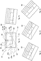
- Fig. 1a shows an example of a sensor part 16.
- That sensor part 16 is preferably a first sensor part and preferably ring shaped.
- Ring shaped preferably means circular shaped or rectangular, in particular quadratic, shaped.
- the first ring shaped sensor part 16 comprises multiple conductive wall members 23a-h forming multiple inner surfaces 22a-h.
- the surfaces 22a-h and/or the wall members 23a-h are preferably electrically isolated from each other. Electrically isolated means that an isolating material or substance is arranged between two neighboring wall members or surfaces. Said isolating material or substance preferably has an electric resistance of more than 10 8 ⁇ cm, in particularly of more than 10 9 ⁇ or of more than 10 10 ⁇ cm.
- Each wall member 22a-h preferably comprises a contact 26 for closing a circuit with contact 20 (cf. Fig. 2a ). Contact 26 can be considered as second contact since contact 20 can be considered as first contact.
- Reference number 24 indicates a virtual center of the entirety of surfaces 22a-h.
- Reference number C indicates a circumferential direction, wherein the wall members 23a-h and/or the surfaces 22a-h are arranged side by side in said direction.
- Fig. 1b shows a further example of a sensor part 32.
- That sensor part 32 is preferably a second senor part and preferably ring shaped.
- the second ring shaped sensor part 32 comprises an inner surface 34 facing the virtual center 24.
- the inner surface 34 is conductive, wherein the inner surface 34 is part of conductive wall member 35.
- Wall member 35 comprises at least one contact 36 or exactly one contact 36 for closing a circuit with contact 20 (cf. Fig. 2a ).
- Contact 36 can be considered as third contact.
- Reference number C2 indicates a circumferential direction, wherein the wall member 35 and/or the surface 34 preferably completely extends into said circumferential direction.
- Fig. 1c shows an example of a sensor unit 10.
- That sensor unit 10 comprises a receiving space 14.
- a conductive liquid 18 is arranged in said receiving space 14.
- Reference number 60 indicates an upper surface level of the conductive liquid 18.
- the upper surface level 60 of the conductive liquid 18 is spaced apart form surfaces 22a-h of a first sensor part 16 in a default configuration.
- Preferably conductive surface 34 of the second sensor part 32 is arranged in a coaxial manner above the first sensor part 16.
- conductive surface 40 of a third sensor part 38 (cf. Fig. 2a ) is arranged in a coaxial manner above the second sensor part 32.
- conductive surface 50 of a fourth sensor part 41 (cf. Fig. 2a ) is arranged in a coaxial manner above the third sensor part 38.
- the individual sensor parts 16, 32, 38, 41 are preferably electrically isolated from each other. Electrically isolated means that an isolating material or substance is arranged between two neighboring sensor parts, thus electrically conductive sections of said neighboring sensor parts preferably do not directly contact each other. Said isolating material or substance preferably has an electric resistance of more than 10 8 ⁇ cm, in particularly of more than 10 9 ⁇ or of more than 10 10 ⁇ cm.
- Reference number 25 indicates a virtual center axis, wherein the center of each sensor part 16, 32, 38, 41 or of at least two sensor parts is positioned on said center axis.
- Fig. 2a schematically shows a side view of the sensor unit shown in Fig. 1c .
- This side view shows a default configuration.
- the level 60 of the conductive liquid 18 inside the receiving space 14 is spaced apart form the first sensor part 16.
- the receiving space 14 comprises a first contact 20, in particularly for closing a circuit with another contact 26, 36, 42.
- Said contact 20 is preferably arranged at the bottom 19 or a side wall of the receiving space 20, wherein the bottom 19 is preferably electrically conductive.
- Reference number 26 indicates contacts preferably arranged on the outside of wall members 23a-h.
- the second sensor part 32 preferably comprises only one contact 36, which is preferably arranged on the outside of wall member 35 (cf. Fig. 1b ).
- the third sensor part 38 preferably comprises only one contact 42, which is preferably arranged on the outside of wall member 62. Additionally, or alternatively the fourth sensor part 41 preferably comprises only one contact 44, which is preferably arranged on the outside of wall member 64.
- Fig. 2b schematically shows a first inclined configuration.
- this first inclined configuration only one surface (of 23a-h) is contacted by the conductive liquid 18.
- a circuit is closed and power can flow from one of the contacts 20 to the other contact 26 (or vice versa). Since the position of the respective surface (the one of 23a-h) is known, it is known in which direction the conductive liquid 18 is flowed and therefore the direction of inclination can be derived from the properties of the closed circuit.
- Fig. 2c schematically shows a second inclined configuration.
- the sensor unit 10 is more inclined compared to the first inclined configuration.
- the conductive liquid contacts the second sensor part 32 but not the third sensor part 38.
- the circuit between contact 20 and contact 36 is closed by means of the conductive liquid 18. Since the height of the respective surface 34 (cf. Fig. 1c ) is known, it is known in which inclination range the sensor unit 10 is inclined with respect to the horizontal axis.
- Fig. 2d schematically shows a third inclined configuration.
- the sensor unit 10 is more inclined compared to the second inclined configuration.
- the conductive liquid contacts the third sensor part 38 but not the fourth sensor part 41.
- the circuit between contact 20 and contact 42 is closed by means of the conductive liquid 18. Since the height of the respective surface 42 (cf. Fig. 1c ) is known, it is known in which inclination range the sensor unit 10 is inclined with respect to the horizontal axis.
- Fig. 2e schematically shows a fourth inclined configuration.
- the sensor unit 10 is more inclined compared to the third inclined configuration.
- the conductive liquid contacts the fourth sensor part 41.
- the circuit between contact 20 and contact 44 is closed by means of the conductive liquid 18. Since the position of the respective surface 42 (cf. Fig. 1c ) is known, it is known in which inclination or above which inclination the sensor unit 10 is inclined with respect to the horizontal axis.
- Fig. 3a schematically shows an example of a charging station 1 according to the present invention.
- That charging station 1 preferably comprises a housing 4 and a power outlet 6.
- Preferably comprises the charging station a cable 7 which is connected to the power outlet 6 and which comprises a connection plug 9 for connecting to an electric vehicle 2.
- the charging station 1 does not comprise such a cable 7 and users always have to attach an own cable to the power outlet 6.
- the charging station 1 also comprises a power supply unit 12 which interrupts or allows power flow from a source 5 via power line 13 to the power outlet 6.
- the power supply 12 is preferably controlled by control unit 8.
- Control unit 8 and the power supply unit 12 are preferably connected via a data or signal connection 15.
- the control unit 8 is preferably connected via a data and/or signal and/or power connection 17 with sensor unit 10.
- Electric energy for establishing power supply via a closed circuit in the senor unit 10 is preferably also provided via connection 17. However, it is also conceivable that electric energy is provided via an additional or alternative connection.
- the control unit 8 receives data or signals from the sensor unit 10 that represent an inclination above a predefined threshold and/or in a predefined direction the control unit 8 causes the power supply unit 12 to interrupt power supply, in particularly immediately.
- Reference number 11 indicates an optional display for inputting commands and/or for displaying the status of the charging station 1 and/or for displaying a charging status.
- Fig. 3b schematically shows charging of an elective vehicle 2 by means of the charging station 1 according to the present invention.
- Reference number 28 indicates the longitudinal direction of the charging station 1 and/or of the housing 4.
- the present invention refers to a charging station 1 for charging at least one electric vehicle 2, in particularly at least one electric car.
- Said charging station comprises: A housing 4, wherein the housing 4 has a column like shape, wherein a power outlet 6 is arranged or attached at the outside of the housing 4, wherein the power outlet 6 is at least indirectly, and preferably directly, connectable to the electric vehicle 2 for charging the electric vehicle 2, wherein at least an electric control unit 8, a sensor unit 10 for sensing movements or the charging station 1 and a power supply unit 12 are arranged inside said housing 4, wherein the electric control unit 8 controls power flow from the power supply unit 12 to the power outlet 6, wherein the sensor unit 10 provides sensor signal or sensor data representing an inclination and/or a direction of inclination, wherein the sensor unit 10 comprises a receiving space 14 and a first ring shaped sensor part 16, wherein the receiving space 14 is preferably at least partially filled with a conductive liquid 18, wherein the conductive liquid 18 is electrically coupled with a first contact 20, wherein the first ring shaped sensor part
- conductive surfaces are preferably designed in such a way that the shape shall be determined according to the sensitivity requirement in the enclosed container.
- a conductive liquid will be added to the container and the container will be placed preferably in the appropriate upper part of the vehicle charging station, wherein an upper part is preferably above 50% of the height of the charging station, in particularly above 70% of the height of the charging station, in particularly above 80% of the height of the charging station, in particularly above 90% of the height of the charging station, in particularly above 95% of the height of the charging station.
- the circuit will be completed by the conductive liquid that touches the sensor pins respectively contacts respectively conductive surface or conductive surface section on the test surface according to the impact direction occurring in the product and the user will be able to easily detect an impact direction. With the help of a simple microcontroller, both the mechanically crashed direction and the angle of inclination will be learned and if there is a dangerous situation, the system power can be cut off automatically.
Landscapes
- Engineering & Computer Science (AREA)
- Power Engineering (AREA)
- Transportation (AREA)
- Mechanical Engineering (AREA)
- Charge And Discharge Circuits For Batteries Or The Like (AREA)
Abstract
Description
- The present invention refers according to
claim 1 to a charging station for charging electric vehicles and according toclaim 15 to a method for charging electric vehicles. - Document
KR20120097107A - Document
WO2013020284 discloses a charging pole. The charging pole comprises a main switch, a main contactor, a second contactor, a charging coupler, at least one sensor and a control unit. The sensor is used to detect acceleration and/or a tilt angle of the charging pole due to a transient outside force, for example a collision force caused by the EV driver's mis-operation. When the acceleration and/or the tilt angle is beyond a preset threshold, the control unit will instruct the main contactor to break the power contact of the charging coupler, so that the charging pole will be power-off. - Document
RU188167U1 - Document
JP2010263666A - Document
CN109795349A discloses a charging pile system, that comprises a server, a plurality of charging piles connected with server signal and a plurality of maintenance interactive terminals connected with the server. Each charging pile comprises a main flow module, a fault self-detection module connected with the main flow module, a communication module connected with the fault detection module and a positioning module connected with the communication module; the main communication module is provided with an input end and an output end and includes an input protection module, and the input protection module is connected between the input end and the output end of the main flow module; the fault self-detection module detects the internal environment of the charging piles and generates fault detection signals; the input protection module generates protection action according to the fault detection signals; the communication module locates the pile positioning information of the modules according to the fault detection signals and generates maintenance request signals; the server sends maintenance assignment messages to the maintenance interactive terminals according to the maintenance request signals, maintenance efficiency of the charging piles is improved. - Thus, a car charger has inputs and outputs which has high power. Some careless drivers may hit the charging station after the charge has run out or when approaching the charging station for charging. This can be very dangerous for the car and driver. Because the high current and voltage inputs and outputs in the charging station are located on the station. A problem with the system isolation as a result of impact may cause damage to the user or the car. In this case, it is a requirement for both the health of the driver and the safety of the car that the system detects the impact and activates the subsequent safety protocols.
- Thus, it is the object of the present invention to enhance safeness of charging stations for charging electric vehicles.
- The before mentioned object is solved by a charging station, in particularly a pole-like charging station, according to
claim 1. Said charging station is preferably a charging station for charging at least one electric vehicles, in particularly at least one electric car. Said charging station preferably comprises at least a housing, wherein the housing has a column like shape, in particularly a straight column. A power outlet is preferably arranged or attached at the outside of the housing, wherein the power outlet is at least indirectly, and preferably directly, connectable to an electric vehicle for charging the electric vehicle. - At least an electric control unit, a sensor unit for sensing movements or the charging station and/or a power supply unit are preferably at least partially or completely arranged inside said housing. The electric control unit preferably controls power flow from the power supply unit to the power outlet. The sensor unit preferably provides sensor signal or sensor data representing an inclination and/or a direction of inclination, wherein the sensor unit preferably comprises a receiving space and a first - preferably ring shaped - sensor part, wherein the receiving space is at least partially filled with a conductive liquid, wherein the conductive liquid is preferably electrically coupled with a first contact.
- The first ring shaped sensor part preferably forms one conductive surface or a plurality of conductive surfaces or surface sections facing a center of the first ring shaped sensor part. Each conductive surface or surface section is preferably coupled with at least one second contact. In a default configuration the plurality of surfaces or surface sections is preferably spaced apart from the conductive liquid and wherein in the default configuration a longitudinal axis of the charging station matches with a vertical axis.
- In a first inclined configuration the longitudinal axis of the charging station is preferably inclined in an angle above a predefined threshold with respect to the vertical axis. The conductive liquid preferably connects in the first inclined configuration the first contact and via at least one of the conductive surfaces or via at least one of the conductive surface sections at least the second contact or at least one second contact. The sensor unit preferably provides sensor signals or sensor data in dependency of the respective conductive surface or surface section which is/are in contact with the conductive liquid in the first inclined configuration, wherein the sensor signals or sensor data represent the inclination and/or the direction of inclination. The control unit preferably processes the sensor signals or sensor data and interrupts power supply in case the inclination represented by the sensor signal or sensor data is above a predefined inclination threshold and/or in case the direction of inclination represented by the sensor signal or sensor data represents a predefined direction of inclination.
- This solution is beneficial since an impact on a charging station, in particularly by a vehicle, can be detected in a reliable manner. Furthermore, inclination and/or orientation of the inclination can be detected.
- Further embodiments are described by the dependent claims and/or the following specification parts.
- The conductive surfaces or surface sections are according to a further preferred embodiment of the present invention part of one or multiple elements, in particularly wall member/s or wall section/s, which differ in electric resistance from each other. This embodiment is beneficial since the individual elements can be designed with different shapes (E.g. thick, thin) or different materials (cupper, steal, iron, aluminum, ceramic) to set up differing conductivity properties.
- Each of the conductive surfaces or surface sections comprises according to a further preferred embodiment of the present invention a second contact, wherein the respective level of current and/or level of voltage per conductive surface or surface section differs from the level of current and/or level of voltage of the other conductive surfaces or surface sections. This embodiment is beneficial since each possible circuit comprises different current and/or voltage properties. Thus, in dependency of the measured or evaluated properties it can be determined in which direction the conductive liquid flowed.
- The center axis of the first ring shaped sensor part extends according to a further preferred embodiment of the present invention in the default configuration in parallel or coaxial to the vertical axis. This embodiment is beneficial since a distance between the receiving space and the first ring shaped part is preferably constant. Thus, the flow path of the conductive liquid for closing a circuit has preferably the same length (starting from a default position) for each of the circuits which might be set up between the first contact and any of the second contacts.
- The first ring shaped sensor part, comprises according to a further preferred embodiment of the present invention at least four and preferably eight or sixteen conductive surfaces or surface sections, wherein said conductive surfaces or surface sections are electrically isolated from each other. This embodiment is beneficial since due to the isolation members cross-talking between two neighboring surfaces or surface sections can be avoided, thus the quality of the detected signals is enhanced.
- A second- preferably ring shaped - sensor part is arranged according to a further preferred embodiment of the present invention in coaxial manner above the first ring shaped sensor part, wherein the first ring shaped sensor part is arranged between the second ring shaped sensor part and the receiving space, wherein the second ring shaped sensor part comprises one conductive surface facing the center axis, wherein the conductive surface at least mainly and preferably completely extends along long a circumferential direction, wherein the conductive surface of the second ring shaped part is coupled with a third contact. This embodiment is beneficial since due to the plurality of sensor parts the inclination respectively a degree of inclination can be determined in a reliable manner. Thus, in case the conductive liquid contacts the second ring shaped sensor part it is clear that the inclination of the charging station must be larger compared to a situation in which the liquid only contacts the first ring shaped sensor part.
- Thus, in a second inclined configuration the conductive liquid contacts one or at least one conductive surface or one or at least one conductive surface section of the first ring shaped sensor part and the conductive surface of the second ring shaped sensor part, wherein the sensor unit provides second sensor signals or second sensor data in case the conductive liquid also contacts the conductive surface of the second ring shaped sensor part, wherein the second sensor signals or second sensor data represents the inclination and/or the direction of inclination.
- A second ring shaped sensor part is arranged according to a further preferred embodiment of the present invention in coaxial manner above the first ring shaped sensor part, wherein the second ring shaped sensor part forms a plurality of conductive surfaces or surface sections facing a center of the second ring shaped sensor part, wherein each conductive surface or surface section is coupled with at least one third contact, wherein in a default configuration the plurality of surfaces or surface sections is spaced apart from the conductive liquid. In a second inclined configuration the conductive liquid preferably contacts one or at least one conductive surface or one or at least one conductive surface section of the first ring shaped sensor part and preferably one or at least one conductive surface, in particularly of a plurality of conductive surfaces, or one or at least one conductive surface section, in particularly of a plurality of conductive surface sections, of the second ring shaped sensor part. The conductive liquid preferably connects in the second inclined configuration the first contact and via the conductive surface or surface section the at least second contact or at least one second contact of the first ring shaped part. The conductive liquid preferably connects in the second inclined configuration via the conductive surface or surface section of the second ring shaped part the one third contact or at least one third contact of the second ring shaped part. The sensor unit preferably provides sensor signals or sensor data in dependency of the respective conductive surface or surface section of the second ring shaped part which is/are in contact with the conductive liquid in the second inclined configuration, wherein the sensor signals or sensor data represent the inclination and/or the direction of inclination. The control unit preferably processes the sensor signals or sensor data and interrupts power supply in case the inclination represented by the sensor signal or sensor data is above a predefined inclination threshold and/or in case the direction of inclination represented by the sensor signal or sensor data represents a predefined direction of inclination.
- This embodiment is beneficial since multiple sensor parts, in particularly ring-shaped sensor parts, can comprise multiple conductive surfaces or surface sections. Thus, the inclination and/or orientation of inclination can be detected or evaluated in a more detailed manner in case multiple or each sensor part has several surfaces or surface section for closing circuits with different properties.
- A third - preferably ring shaped - sensor part is arranged according to a further preferred embodiment of the present invention in coaxial manner above the second ring shaped sensor part, wherein the second ring shaped sensor part is arranged between the first ring shaped sensor part and the third ring shaped sensor part, wherein the third ring shaped sensor part comprises one conductive surface facing the center axis, wherein the conductive surface at least mainly and preferably completely extends along long a circumferential direction, wherein the conductive surface of the third ring shaped part is preferably coupled with a fourth contact. This embodiment is beneficial since a larger range of inclination can be detected in case a third sensor part is part of the sensor unit. However, it is conceivable that further sensor parts, in particularly ring-shaped sensor parts, like a fourth, fifth or sixth or up to ten or up to twenty preferably coaxial arranged sensor parts are provided. Thus, in a third inclined configuration the conductive liquid contacts preferably one or at least one conductive surface or one or at least one conductive surface section of the first ring shaped sensor part and the conductive surface of the second ring shaped sensor part and the conductive surface of the third ring shaped sensor part. The sensor unit preferably provides third sensor signals or third sensor data in case the conductive liquid also contacts the conductive surface of the third ring shaped sensor part, wherein the third sensor signals or third sensor data represents the inclination and/or the direction of inclination.
- A third ring shaped sensor part is arranged according to a further preferred embodiment of the present invention in coaxial manner above the second ring shaped sensor part, wherein the third ring shaped sensor part preferably forms a plurality of conductive surfaces or surface sections facing a center of the third ring shaped sensor part, wherein each conductive surface or surface section is preferably coupled with at least one fourth contact, wherein in a default configuration the plurality of surfaces or surface sections is preferably spaced apart from the conductive liquid. In a third inclined configuration the conductive liquid preferably contacts one or at least one conductive surface or one or at least one conductive surface section of the third ring shaped sensor part and one or at least one conductive surface or one or at least one conductive surface section of the second ring shaped sensor part and one or at least one conductive surface or one or at least one conductive surface section of the first ring shaped sensor part.
- The conductive liquid preferably connects in the third inclined configuration the first contact and via the conductive surface or surface section the at least second contact or at least one second contact of the first ring shaped part and wherein the conductive liquid preferably connects in the third inclined configuration via the conductive surface or surface section of the second ring shaped part the one third contact or at least one third contact of the second ring shaped part and wherein the conductive liquid connects in the third inclined configuration via the conductive surface or surface section of the third ring shaped part the one fourth contact or at least one fourth contact of the third ring shaped part. The sensor unit preferably provides sensor signals or sensor data in dependency of the respective conductive surface or surface section of the third ring shaped part which is/are in contact with the conductive liquid in the second inclined configuration, wherein the sensor signals or sensor data represent the inclination and/or the direction of inclination. The control unit preferably processes the sensor signals or sensor data and interrupts power supply in case the inclination represented by the sensor signal or sensor data is above a predefined inclination threshold and/or in case the direction of inclination represented by the sensor signal or sensor data represents a predefined direction of inclination.
- This embodiment is beneficial since multiple sensor parts, in particularly ring-shaped sensor parts, can comprise multiple conductive surfaces or surface sections. Thus, the inclination and/or orientation of inclination can be detected or evaluated in a more detailed manner in case multiple or each sensor part has several surfaces or surface section for closing circuits with different properties.
- The first contact is according to a further preferred embodiment of the present invention permanently biased with current and/or voltage. This embodiment is beneficial since power flow is established in case the conductive liquid contacts any of the conductive surfaces or surface sections. The properties of the power flow hereby preferably depend on the conductive surface or surface section the conductive liquid is flowing to in response to a tilting movement of the charging station.
- The second contact or each second contact is according to a further preferred embodiment of the present invention permanently biased with current and/or voltage and/or the third contact or each third contact is permanently biased with current and/or voltage, and/or the fourth contact or each fourth contact is permanently biased with current and/or voltage. Preferably differs the current and/or voltage from conductive surface or surface section to conductive surface or surface section. Preferably each conductive surface or surface section is biased with a different current and/or voltage. Preferably each conductive surface or surface section of a sensor part is biased with a different current and/or voltage. It is possible that the two or multiple or the majority or all sensor parts are designed in an identical manner. This embodiment is beneficial since closing of a circuit is established in case the conductive liquid contacts any of the conductive surfaces or surface sections. Since the properties of the power flowing within said closed circuit are known it is known which conductive surface or surface section the conductive liquid contacts, thus it is known in which direction the inclination is oriented.
- An angle between the longitudinal axis of the charging station and a horizontal axis is according to a further preferred embodiment of the present invention smaller in the second inclined configuration compared to the first inclined configuration and an angle between the longitudinal axis of the charging station and the horizontal axis is smaller in the third inclined configuration compared to the second inclined configuration. This embodiment is beneficial since the inclination can be determined in a very precise manner.
- The conductivity of the conductive liquid is according to a further preferred embodiment of the present invention above 5x10⁻⁶ S/m, in particularly above 5x10⁻³ S/m or above 5x100 S/m or above 1x10² S/m or above 1x10³ S/m or above 1x10⁴ S/m or above 1x10⁶ S/m or above 1x10⁶ S/m or above 1x10² S/m. This embodiment is beneficial since the conductive liquid can be selected in such a manner to fit best into the overall sensor setting.
- The conductive liquid is according to a further preferred embodiment of the present invention a metal, in particularly mercury, or an alloy, in particularly an alloy comprising alkali metals or consisting of alkali metals or an alloy comprising gallium, in particularly Galinstan, or an alloy comprising mercury, or an electrolyte solution, in particularly ethanoic acid or sulfuric acid. This embodiment is beneficial since the conductive liquid can be selected in such a manner to fit best into the overall sensor setting.
- The above-mentioned object is also solved by a method according to claim 15 for interrupting power supply from a charging station to at least one electric vehicle, in particularly electric car. Said method preferably at least comprises the steps: Providing a charging station, wherein the charging station comprises a housing, wherein the housing preferably has a column like shape, wherein the charging station comprises a power outlet, wherein the power outlet is arranged or attached at the outside of the housing, wherein the power outlet is connected to the electric vehicle for charging the electric vehicle, wherein at least a power supply unit for providing power flow to the power outlet, an electric control unit for controlling power flow from the power supply unit to the electric vehicle and/or a sensor unit for sensing movements of the charging station is/are part of the charging station, wherein the sensor unit preferably comprises a receiving space and a first - preferably ring shaped - sensor part, wherein the receiving space is at least partially filled with a conductive liquid, wherein the conductive liquid is electrically coupled with a first contact, wherein the first sensor part preferably forms at least one or a plurality of conductive surfaces or surface sections facing a center of the first ring shaped sensor part, wherein each conductive surface or surface section is preferably coupled with at least one second contact, in particularly the same second contact. In a default configuration the plurality of surfaces or surface sections is preferably spaced apart from the conductive liquid and wherein in the default configuration a longitudinal axis of the charging station preferably matches with a vertical axis. Tilting the charging station into a first inclined configuration, wherein in the first inclined configuration the longitudinal axis of the charging station is inclined in an angle above a predefined threshold with respect to the vertical axis, wherein the conductive liquid connects in the first inclined configuration the first contact via the conductive surface or surface section to at least the second contact or at least one second contact. Providing sensor signal or sensor data by the sensor unit, wherein the sensor unit provides sensor signals or sensor data in dependency of the respective conductive surface or surface section which is/are in contact with the conductive liquid in the first inclined configuration, wherein the sensor signal or sensor data represent the inclination and/or the direction of inclination. Processing the sensor signals or sensor data by the control unit. Interrupting power supply in case the processed sensor signal or sensor data represents a predefined inclination threshold and/or in case the direction of inclination represented by the sensor signal or sensor data represents a predefined direction of inclination. Interrupting power supply is preferably carried out by shifting a physical switch, which is controlled by the control unit respectively commands for switching the physical switch are provided by the control unit.
- The present invention might refer to a sensor unit. Said sensor unit is described before and in the following. However, said sensor unit preferably at least comprises the following features: a receiving space and a first sensor part, in particularly ring shaped, wherein the receiving space is at least partially filled with a conductive liquid, wherein the conductive liquid is electrically coupled with a first contact, wherein the first sensor part forms a plurality of conductive surfaces or surface sections facing a center of the first sensor part, wherein each conductive surface or surface section is coupled with at least one second contact, wherein in a default configuration the plurality of surfaces or surface sections is spaced apart from the conductive liquid and wherein in the default configuration a longitudinal axis of the charging station matches with a vertical axis. The conductive liquid connects in a first inclined configuration the first contact and via at least one of the conductive surfaces or via at least one of the conductive surface sections at least the second contact or at least one second contact. The sensor unit preferably provides sensor signals or sensor data in dependency of the respective conductive surface or surface section which is/are in contact with the conductive liquid in the first inclined configuration, wherein the sensor signals or sensor data represent the inclination and/or the direction of inclination.
- If not otherwise indicated the word "conductive" is used in view of the present invention in the sense of "electrically conductive".
- Further features, goals and advantages of the present invention will now be described in association with the accompanying drawings, in which exemplary components of the invention are illustrated. Components of the devices and methods according to the invention, which are at least essentially equivalent to each other with respect to their function can be marked by the same reference numerals, wherein such components do not have to be marked or described in all of the drawings.
- In the following description, the invention is described by way of example only with respect to the accompanying drawings.
-
- Fig. 1a
- schematically shows an example or a first sensor part;
- Fig. 1b
- schematically shows an example of a second sensor part;
- Fig. 1c
- schematically shows an example of a sensor unit comprising at least the first sensor part and the second sensor part;
- Fig. 2a
- schematically shows a side view of an example of the sensor unit;
- Fig. 2b-e
- schematically show the sensor unit inclined in different angles with respect to the horizontal axis;
- Fig. 3a
- schematically shows an example of a charging station according to the present invention for charging electric vehicles; and
- Fig. 3b
- schematically shows a situation in which an electric vehicle becomes charged by the charging station.
-
Fig. 1a shows an example of asensor part 16. Thatsensor part 16 is preferably a first sensor part and preferably ring shaped. Ring shaped preferably means circular shaped or rectangular, in particular quadratic, shaped. - The first ring shaped
sensor part 16 comprises multipleconductive wall members 23a-h forming multipleinner surfaces 22a-h. Thesurfaces 22a-h and/or thewall members 23a-h are preferably electrically isolated from each other. Electrically isolated means that an isolating material or substance is arranged between two neighboring wall members or surfaces. Said isolating material or substance preferably has an electric resistance of more than 108 Ω·cm, in particularly of more than 109 Ω·or of more than 1010 Ω·cm. Eachwall member 22a-h preferably comprises acontact 26 for closing a circuit with contact 20 (cf.Fig. 2a ).Contact 26 can be considered as second contact sincecontact 20 can be considered as first contact.Reference number 24 indicates a virtual center of the entirety ofsurfaces 22a-h. Reference number C indicates a circumferential direction, wherein thewall members 23a-h and/or thesurfaces 22a-h are arranged side by side in said direction. -
Fig. 1b shows a further example of asensor part 32. Thatsensor part 32 is preferably a second senor part and preferably ring shaped. The second ring shapedsensor part 32 comprises aninner surface 34 facing thevirtual center 24. Theinner surface 34 is conductive, wherein theinner surface 34 is part ofconductive wall member 35.Wall member 35 comprises at least onecontact 36 or exactly onecontact 36 for closing a circuit with contact 20 (cf.Fig. 2a ).Contact 36 can be considered as third contact. Reference number C2 indicates a circumferential direction, wherein thewall member 35 and/or thesurface 34 preferably completely extends into said circumferential direction. -
Fig. 1c shows an example of asensor unit 10. Thatsensor unit 10 comprises a receivingspace 14. Aconductive liquid 18 is arranged in said receivingspace 14.Reference number 60 indicates an upper surface level of theconductive liquid 18. Theupper surface level 60 of theconductive liquid 18 is spaced apart form surfaces 22a-h of afirst sensor part 16 in a default configuration. Thus, power flow though a circuit is avoided since no circuit is closed in the default configuration. Preferablyconductive surface 34 of thesecond sensor part 32 is arranged in a coaxial manner above thefirst sensor part 16. Additionally, or alternativelyconductive surface 40 of a third sensor part 38 (cf.Fig. 2a ) is arranged in a coaxial manner above thesecond sensor part 32. Additionally, or alternativelyconductive surface 50 of a fourth sensor part 41 (cf.Fig. 2a ) is arranged in a coaxial manner above the third sensor part 38. - The
individual sensor parts Fig. 2a ) are preferably electrically isolated from each other. Electrically isolated means that an isolating material or substance is arranged between two neighboring sensor parts, thus electrically conductive sections of said neighboring sensor parts preferably do not directly contact each other. Said isolating material or substance preferably has an electric resistance of more than 108 Ω·cm, in particularly of more than 109 Ω·or of more than 1010 Ω·cm. -
Reference number 25 indicates a virtual center axis, wherein the center of eachsensor part -
Fig. 2a schematically shows a side view of the sensor unit shown inFig. 1c . This side view shows a default configuration. Thelevel 60 of theconductive liquid 18 inside the receivingspace 14 is spaced apart form thefirst sensor part 16. The receivingspace 14 comprises afirst contact 20, in particularly for closing a circuit with anothercontact contact 20 is preferably arranged at the bottom 19 or a side wall of the receivingspace 20, wherein the bottom 19 is preferably electrically conductive.Reference number 26 indicates contacts preferably arranged on the outside ofwall members 23a-h. Thesecond sensor part 32 preferably comprises only onecontact 36, which is preferably arranged on the outside of wall member 35 (cf.Fig. 1b ). Additionally, or alternatively the third sensor part 38 preferably comprises only onecontact 42, which is preferably arranged on the outside of wall member 62. Additionally, or alternatively the fourth sensor part 41 preferably comprises only onecontact 44, which is preferably arranged on the outside of wall member 64. -
Fig. 2b schematically shows a first inclined configuration. In this first inclined configuration only one surface (of 23a-h) is contacted by theconductive liquid 18. Thus, a circuit is closed and power can flow from one of thecontacts 20 to the other contact 26 (or vice versa). Since the position of the respective surface (the one of 23a-h) is known, it is known in which direction theconductive liquid 18 is flowed and therefore the direction of inclination can be derived from the properties of the closed circuit. -
Fig. 2c schematically shows a second inclined configuration. In this second inclined configuration thesensor unit 10 is more inclined compared to the first inclined configuration. It can be seen fromFig. 2c that the conductive liquid contacts thesecond sensor part 32 but not the third sensor part 38. Thus, the circuit betweencontact 20 andcontact 36 is closed by means of theconductive liquid 18. Since the height of the respective surface 34 (cf.Fig. 1c ) is known, it is known in which inclination range thesensor unit 10 is inclined with respect to the horizontal axis. -
Fig. 2d schematically shows a third inclined configuration. In this third inclined configuration thesensor unit 10 is more inclined compared to the second inclined configuration. It can be seen fromFig. 2d that the conductive liquid contacts the third sensor part 38 but not the fourth sensor part 41. Thus, the circuit betweencontact 20 andcontact 42 is closed by means of theconductive liquid 18. Since the height of the respective surface 42 (cf.Fig. 1c ) is known, it is known in which inclination range thesensor unit 10 is inclined with respect to the horizontal axis. -
Fig. 2e schematically shows a fourth inclined configuration. In this fourth inclined configuration thesensor unit 10 is more inclined compared to the third inclined configuration. It can be seen fromFig. 2e that the conductive liquid contacts the fourth sensor part 41. Thus, the circuit betweencontact 20 andcontact 44 is closed by means of theconductive liquid 18. Since the position of the respective surface 42 (cf.Fig. 1c ) is known, it is known in which inclination or above which inclination thesensor unit 10 is inclined with respect to the horizontal axis. -
Fig. 3a schematically shows an example of a chargingstation 1 according to the present invention. That chargingstation 1 preferably comprises ahousing 4 and apower outlet 6. Preferably comprises the charging station a cable 7 which is connected to thepower outlet 6 and which comprises aconnection plug 9 for connecting to anelectric vehicle 2. However, it is also conceivable that the chargingstation 1 does not comprise such a cable 7 and users always have to attach an own cable to thepower outlet 6. - The charging
station 1 also comprises apower supply unit 12 which interrupts or allows power flow from asource 5 viapower line 13 to thepower outlet 6. Thepower supply 12 is preferably controlled bycontrol unit 8.Control unit 8 and thepower supply unit 12 are preferably connected via a data orsignal connection 15. Thecontrol unit 8 is preferably connected via a data and/or signal and/orpower connection 17 withsensor unit 10. Electric energy for establishing power supply via a closed circuit in thesenor unit 10 is preferably also provided viaconnection 17. However, it is also conceivable that electric energy is provided via an additional or alternative connection. In case thecontrol unit 8 receives data or signals from thesensor unit 10 that represent an inclination above a predefined threshold and/or in a predefined direction thecontrol unit 8 causes thepower supply unit 12 to interrupt power supply, in particularly immediately. -
Reference number 11 indicates an optional display for inputting commands and/or for displaying the status of the chargingstation 1 and/or for displaying a charging status. -
Fig. 3b schematically shows charging of anelective vehicle 2 by means of the chargingstation 1 according to the present invention.Reference number 28 indicates the longitudinal direction of the chargingstation 1 and/or of thehousing 4. - Thus, the present invention refers to a charging
station 1 for charging at least oneelectric vehicle 2, in particularly at least one electric car. Said charging station comprises: A housing 4, wherein the housing 4 has a column like shape, wherein a power outlet 6 is arranged or attached at the outside of the housing 4, wherein the power outlet 6 is at least indirectly, and preferably directly, connectable to the electric vehicle 2 for charging the electric vehicle 2, wherein at least an electric control unit 8, a sensor unit 10 for sensing movements or the charging station 1 and a power supply unit 12 are arranged inside said housing 4, wherein the electric control unit 8 controls power flow from the power supply unit 12 to the power outlet 6, wherein the sensor unit 10 provides sensor signal or sensor data representing an inclination and/or a direction of inclination, wherein the sensor unit 10 comprises a receiving space 14 and a first ring shaped sensor part 16, wherein the receiving space 14 is preferably at least partially filled with a conductive liquid 18, wherein the conductive liquid 18 is electrically coupled with a first contact 20, wherein the first ring shaped sensor part 16 forms a plurality of conductive surfaces 22a-d or surface sections 22a-d facing a center 24 of the first ring shaped sensor part 16, wherein each conductive surface 22a-d or surface section 22a-d is coupled with at least one second contact 26, wherein in a default configuration the plurality of surfaces 22a-d or surface sections 22a-d is spaced apart from the conductive liquid 18 and wherein in the default configuration a longitudinal axis 28 of the charging station 1 matches with a vertical axis X. - Additionally, or alternatively conductive surfaces are preferably designed in such a way that the shape shall be determined according to the sensitivity requirement in the enclosed container. A conductive liquid will be added to the container and the container will be placed preferably in the appropriate upper part of the vehicle charging station, wherein an upper part is preferably above 50% of the height of the charging station, in particularly above 70% of the height of the charging station, in particularly above 80% of the height of the charging station, in particularly above 90% of the height of the charging station, in particularly above 95% of the height of the charging station. The circuit will be completed by the conductive liquid that touches the sensor pins respectively contacts respectively conductive surface or conductive surface section on the test surface according to the impact direction occurring in the product and the user will be able to easily detect an impact direction. With the help of a simple microcontroller, both the mechanically crashed direction and the angle of inclination will be learned and if there is a dangerous situation, the system power can be cut off automatically.
-
1 charging station 24 center (virtually) 2 electric vehicle 25 center axis (virtually) 4 housing 26 second contact 5 source 28 longitudinal axis 6 power outlet 32 second ring shaped part 7 cable 34 conductive surface of the second ring shaped part 8 control unit 9 connection plug 35 wall member 10 sensor unit 36 third contact 11 display 38 third ring shaped sensor part 12 power supply unit 40 conductive surface of third ring shaped part 13 power line 41 fourth ring shaped sensor part 14 receiving space 42 fourth contact 15 data or signal connection between control unit and power supply unit 44 fifth contact 16 first ring shaped sensor part 50 conductive surface of a fourth ring shaped part 17 data and/or signal and/or power connection between control unit and sensor unit 60 liquid level 62 wall member of third sensor part 18 conductive liquid 64 wall member of fourth sensor part 19 conductive bottom of receiving space C circumferential direction 20 first contact C2 second circumferential direction 22a-h conductive surfaces / conductive surface sections X vertical axis 23a-h wall member Y horizontal axis Z width axis
Claims (15)
- Charging station (1) for charging at least one electric vehicles (2), in particularly at least one electric car,
at least comprising
a housing (4),
wherein the housing (4) has a column like shape,
wherein a power outlet (6) is arranged or attached at the outside of the housing (4),
wherein the power outlet (6) is at least indirectly, and preferably directly, connectable to the electric vehicle (2) for charging the electric vehicle (2).
wherein at least an electric control unit (8), a sensor unit (10) for sensing movements or the charging station (1) and a power supply unit (12) are arranged inside said housing (4),
wherein the electric control unit (8) controls power flow from the power supply unit (12) to the power outlet (6)
wherein the sensor unit (10) provides sensor signal or sensor data representing an inclination and/or a direction of inclination,
wherein the sensor unit (10) comprises a receiving space (14) and a first ring shaped sensor part (16), wherein the receiving space (14) is at least partially filled with a conductive liquid (18), wherein the conductive liquid (18) is electrically coupled with a first contact (20)
wherein the first ring shaped sensor part (16) forms a plurality of conductive surfaces (22a-d) or surface sections (22a-d) facing a center (24) of the first ring shaped sensor part (16),
wherein each conductive surface (22a-d) or surface section (22a-d) is coupled with at least one second contact (26), wherein in a default configuration the plurality of surfaces (22a-d) or surface sections (22a-d) is spaced apart from the conductive liquid (18) and wherein in the default configuration a longitudinal axis (28) of the charging station (1) matches with a vertical axis (X),
wherein in a first inclined configuration the longitudinal axis (28) of the charging station (1) is inclined in an angle above a predefined threshold with respect to the vertical axis (X),
wherein the conductive liquid (18) connects in the first inclined configuration the first contact (20) and via at least one of the conductive surfaces (22a-d) or via at least one of the conductive surface sections (22a-d) at least the second contact (26) or at least one second contact (26),
wherein the sensor unit (10) provides sensor signals or sensor data in dependency of the respective conductive surface (22a-d) or surface section (22a-d) which is/are in contact with the conductive liquid in the first inclined configuration, wherein the sensor signals or sensor data represent the inclination and/or the direction of inclination,
wherein the control unit (8) processes the sensor signals or sensor data and interrupts power supply in case the inclination represented by the sensor signal or sensor data is above a predefined inclination threshold and/or in case the direction of inclination represented by the sensor signal or sensor data represents a predefined direction of inclination. - Charging station according to claim 1,
characterized in that
the conductive surfaces (22a-d) or surface sections (22a-d) are part of one or multiple elements, in particularly wall member/s or wall section/s, which differ in electric resistance from each other. - Charging station according to claim 1 or2,
characterized in that
each of the conductive surfaces (22a-d) or surface sections (22a-d) comprises a second contact (26), wherein the respective level of current and/or level of voltage per conductive surface or surface section differs from the level of current and/or level of voltage of the other conductive surfaces (22a-d) or surface sections (22a-d). - Charging station according to claim 1 to 3,
characterized in that
the center axis (25) of the first ring shaped sensor part (16) extends in the default configuration in parallel or coaxial to the vertical axis (X). - Charging station according to claim 1 to 4,
characterized in that
the first ring shaped sensor part (16) comprises at least four and preferably eight or sixteen conductive surfaces (22a-d) or surface sections (22a-d), wherein said conductive surfaces (22a-d) or surface sections (22a-d) are electrically isolated from each other. - Charging station according to claim 1 to 5,
characterized in that
a second ring shaped sensor part (32) is arranged in coaxial manner above the first ring shaped sensor part (16), wherein the first ring shaped sensor part (16) is arranged between the second ring shaped sensor part (32) and the receiving space (14), wherein the second ring shaped sensor part (32) comprises one conductive surface (34) facing the center axis (25), wherein the conductive surface (34) at least mainly and preferably completely extends along long a second circumferential direction (C2), wherein the conductive surface (34) of the second ring shaped part (32) is coupled with a third contact (36). - Charging station according to claim 6,
characterized in that
in a second inclined configuration the conductive liquid (18) contacts one or at least one conductive surface (22a-d) or one or at least one conductive surface section (22a-d) of the first ring shaped sensor part (16) and the conductive surface (34) of the second ring shaped sensor part (32), wherein the sensor unit (10) provides second sensor signals or second sensor data in case the conductive liquid (18) also contacts the conductive surface (34) of the second ring shaped sensor part (32), wherein the second sensor signals or second sensor data represents the inclination and/or the direction of inclination. - Charging station according to claim 6 or 7,
characterized in that
a third ring shaped sensor part (38) is arranged in coaxial manner above the second ring shaped sensor part (32), wherein the second ring shaped sensor part (32) is arranged between the first ring shaped sensor part (16) and the third ring shaped sensor part (38), wherein the third ring shaped sensor part (38) comprises one conductive surface (40) facing the center axis (25), wherein the conductive surface (40) at least mainly and preferably completely extends along long a third circumferential direction (C3), wherein the conductive surface (40) of the third ring shaped part (38) is coupled with a fourth contact (42). - Charging station according to claim 8,
characterized in that
in a third inclined configuration the conductive liquid (18) contacts one or at least one conductive surface (22a-d) or one or at least one conductive surface section (22a-d) of the first ring shaped sensor part (16) and the conductive surface (34) of the second ring shaped sensor part (32) and the conductive surface (40) of the third ring shaped sensor part (38), wherein the sensor unit (10) provides third sensor signals or third sensor data in case the conductive liquid (18) also contacts the conductive surface (40) of the third ring shaped sensor part (38), wherein the third sensor signals or third sensor data represents the inclination and/or the direction of inclination. - Charging station according to claims 1 to 9,
characterized in that
the first contact (20) is permanently biased with current and/or voltage, - Charging station according to claims 6 to 9,
characterized in that
the second contact (26) or each second contact (26) is permanently biased with current and/or voltage
and/or
the third contact (36) or each third contact (36) is permanently biased with current and/or voltage,
and/or
the fourth contact or each fourth contact is permanently biased with current and/or voltage, - Charging station according to claims 6 to 11,
characterized in that
an angle between the longitudinal axis (28) of the charging station (1) and a horizontal axis (Z) is smaller in the second inclined configuration compared to the first inclined configuration.
and
an angle between the longitudinal axis (28) of the charging station (1) and the horizontal axis (Y) is smaller in the third inclined configuration compared to the second inclined configuration. - Charging station according to claims 1 to 12,
characterized in that
the conductivity of the conductive liquid (18) is above 5x10⁻⁶ S/m, in particularly above 5x10⁻³ S/m or above 5x100 S/m or above 1x10² S/m or above 1x10³ S/m or above 1x10⁴ S/m or above 1x10⁶ S/m or above 1x10⁶ S/m or above 1x10² S/m. - Charging station according to claims 1 to 13,
characterized in that
the conductive liquid (18) is a metal, in particularly mercury, or an alloy, in particularly an alloy comprising alkali metals or consisting of alkali metals or an alloy comprising gallium, in particularly Galinstan, or an alloy comprising mercury, or an electrolyte solution, in particularly ethanoic acid or sulfuric acid. - Method for interrupting power supply from a charging station (1) to at least one electric vehicle (2), in particularly electric car,
at least comprising the steps
providing a charging station (1),wherein the charging station (1) comprises a housing (4),
wherein the housing (4) has a column like shape,wherein the charging station (1) comprises a power outlet (6),wherein the power outlet is arranged or attached at the outside of the housing (4),wherein the power outlet (6) is connected to the electric vehicle (2) for charging the electric vehicle (2),wherein the charging station (1) comprises at least one power supply unit (12) for providing power flow to the power outlet (6), an electric control unit (8) for controlling power flow from the power supply unit (12) to the electric vehicle (2) and a sensor unit (10) for sensing movements of the charging station (1),wherein the sensor unit (10) comprises a receiving space (14) and a first ring shaped sensor part (16), wherein the receiving space (14) is at least partially filled with a conductive liquid (18), wherein the conductive liquid (18) is electrically coupled with a first contact (20),wherein the first ring shaped sensor part (16) forms a plurality of conductive surfaces (22a-d) or surface sections (22a-d) facing a center (24) of the first ring shaped sensor part (16), wherein each conductive surface (22a-d) or surface section (22a-d) is coupled with at least one second contact (26), wherein in a default configuration the plurality of surfaces (22a-d) or surface sections (22a-d) is spaced apart from the conductive liquid (18) and wherein in the default configuration a longitudinal axis (28) of the charging station (1) matches with a vertical axis (X),tilting the charging station (1) into a first inclined configuration,wherein in the first inclined configuration the longitudinal axis (28) of the charging station (1) is inclined in an angle above a predefined threshold with respect to the vertical axis (X),wherein the conductive liquid (18) connects in the first inclined configuration the first contact (20) via the conductive surface (22a-d) or surface section (22a-d) to at least the second contact (26) or at least one second contact (26),providing sensor signal or sensor data by the sensor unit (10),
wherein the sensor unit (10) provides sensor signals or sensor data in dependency of the respective conductive surface (22a-d) or surface section (22a-d) which is/are in contact with the conductive liquid (18) in the first inclined configuration, wherein the sensor signal or sensor data represent the inclination and/or the direction of inclination,processing the sensor signals or sensor data by the control unit (8),
interrupting power supply in case the processed sensor signal or sensor data represents a predefined inclination threshold and/or in case the direction of inclination represented by the sensor signal or sensor data represents a predefined direction of inclination.
Priority Applications (1)
| Application Number | Priority Date | Filing Date | Title |
|---|---|---|---|
| EP20208120.4A EP4000988B1 (en) | 2020-11-17 | 2020-11-17 | Charging station comprising an inclination sensor having a conductive liquid |
Applications Claiming Priority (1)
| Application Number | Priority Date | Filing Date | Title |
|---|---|---|---|
| EP20208120.4A EP4000988B1 (en) | 2020-11-17 | 2020-11-17 | Charging station comprising an inclination sensor having a conductive liquid |
Publications (2)
| Publication Number | Publication Date |
|---|---|
| EP4000988A1 true EP4000988A1 (en) | 2022-05-25 |
| EP4000988B1 EP4000988B1 (en) | 2023-07-05 |
Family
ID=73455639
Family Applications (1)
| Application Number | Title | Priority Date | Filing Date |
|---|---|---|---|
| EP20208120.4A Active EP4000988B1 (en) | 2020-11-17 | 2020-11-17 | Charging station comprising an inclination sensor having a conductive liquid |
Country Status (1)
| Country | Link |
|---|---|
| EP (1) | EP4000988B1 (en) |
Cited By (1)
| Publication number | Priority date | Publication date | Assignee | Title |
|---|---|---|---|---|
| US12574071B2 (en) * | 2023-07-21 | 2026-03-10 | Volkswagen Aktiengesellschaft | Device for the communication of an electric or hybrid vehicle with an electric charging station, and communication method |
Citations (8)
| Publication number | Priority date | Publication date | Assignee | Title |
|---|---|---|---|---|
| JP2010263666A (en) | 2009-04-30 | 2010-11-18 | Nitto Electric Works Ltd | Electric vehicle charging station |
| KR20120097107A (en) | 2011-02-24 | 2012-09-03 | 엘에스산전 주식회사 | Apparatus for charging a battery of electric vehicle with a tilt sensor |
| WO2013020284A1 (en) | 2011-08-10 | 2013-02-14 | Abb Lv Installation Materials Co. Ltd., Beijing | A charging pole for ev and a detecting method thereof |
| CN108045245A (en) * | 2017-12-08 | 2018-05-18 | 重庆市鑫奕星机电制造有限公司 | A kind of automobile charging pile |
| RU188167U1 (en) | 2018-06-14 | 2019-04-02 | Общество с ограниченной ответственностью "Ева" | ELECTRIC CHARGING STATION |
| CN109795349A (en) | 2019-01-02 | 2019-05-24 | 易事特集团股份有限公司 | Charging pile system |
| WO2019215423A1 (en) * | 2018-05-08 | 2019-11-14 | Urban Electric Networks Ltd | Electric vehicle charging station |
| US20200009967A1 (en) * | 2018-07-03 | 2020-01-09 | Carlile R Stevens | Safety disconnect system |
-
2020
- 2020-11-17 EP EP20208120.4A patent/EP4000988B1/en active Active
Patent Citations (8)
| Publication number | Priority date | Publication date | Assignee | Title |
|---|---|---|---|---|
| JP2010263666A (en) | 2009-04-30 | 2010-11-18 | Nitto Electric Works Ltd | Electric vehicle charging station |
| KR20120097107A (en) | 2011-02-24 | 2012-09-03 | 엘에스산전 주식회사 | Apparatus for charging a battery of electric vehicle with a tilt sensor |
| WO2013020284A1 (en) | 2011-08-10 | 2013-02-14 | Abb Lv Installation Materials Co. Ltd., Beijing | A charging pole for ev and a detecting method thereof |
| CN108045245A (en) * | 2017-12-08 | 2018-05-18 | 重庆市鑫奕星机电制造有限公司 | A kind of automobile charging pile |
| WO2019215423A1 (en) * | 2018-05-08 | 2019-11-14 | Urban Electric Networks Ltd | Electric vehicle charging station |
| RU188167U1 (en) | 2018-06-14 | 2019-04-02 | Общество с ограниченной ответственностью "Ева" | ELECTRIC CHARGING STATION |
| US20200009967A1 (en) * | 2018-07-03 | 2020-01-09 | Carlile R Stevens | Safety disconnect system |
| CN109795349A (en) | 2019-01-02 | 2019-05-24 | 易事特集团股份有限公司 | Charging pile system |
Cited By (1)
| Publication number | Priority date | Publication date | Assignee | Title |
|---|---|---|---|---|
| US12574071B2 (en) * | 2023-07-21 | 2026-03-10 | Volkswagen Aktiengesellschaft | Device for the communication of an electric or hybrid vehicle with an electric charging station, and communication method |
Also Published As
| Publication number | Publication date |
|---|---|
| EP4000988B1 (en) | 2023-07-05 |
Similar Documents
| Publication | Publication Date | Title |
|---|---|---|
| CN103568847B (en) | For the Vehicle security system of the danger brought that reduces to be got an electric shock by battery | |
| US10566160B2 (en) | Passive triggering mechanisms for use with switching devices incorporating pyrotechnic features | |
| EP3272573A2 (en) | Multipoint emergency responder safety isolation system | |
| WO2015173617A1 (en) | Electrical storage system | |
| US9472800B2 (en) | Contact arrangement for safe disconnection of a power supply in a vehicle | |
| US11511428B2 (en) | Switchgear or controlgear with unmanned operation and maintenance, and method of operating the same | |
| CN103797677B (en) | For charging pile and the detection method thereof of electric automobile | |
| CN104733791B (en) | Safety device for preventing battery from overcharging | |
| JP6734988B2 (en) | Contact system for establishing an electrical connection between a primary device and a secondary device | |
| CN104836210A (en) | Parting unit for electroparting and battery pack system having the parting unit | |
| EP4000988B1 (en) | Charging station comprising an inclination sensor having a conductive liquid | |
| CN104025369A (en) | Battery system and motor vehicle | |
| KR101976873B1 (en) | Relay fusion detecting apparatus and method for high voltage battery system of vehicle | |
| KR20200074914A (en) | Electric control system | |
| US3836739A (en) | Liquid contact tilt inertial switch with movable metallic conductive means responsive to acceleration and deceleration forces | |
| US12097785B2 (en) | Mounted object detection device and vehicle control system | |
| US3675227A (en) | Liquid-level drop alarming system | |
| CN206115648U (en) | Independent alarm device of car accident | |
| KR102684494B1 (en) | Automatic Power-off System Based On Risk Detection | |
| KR102401970B1 (en) | Method And Apparatus for Preventing Battery Overcharge | |
| CN211376545U (en) | A safety on-off control component and PDU controller | |
| KR20240087282A (en) | Electric two-wheeled vehicle and system and charging method thereof | |
| CN108352583A (en) | battery pack system for vehicle | |
| CN211308290U (en) | Charging pile | |
| CN209150746U (en) | Electrode safety device |
Legal Events
| Date | Code | Title | Description |
|---|---|---|---|
| PUAI | Public reference made under article 153(3) epc to a published international application that has entered the european phase |
Free format text: ORIGINAL CODE: 0009012 |
|
| STAA | Information on the status of an ep patent application or granted ep patent |
Free format text: STATUS: THE APPLICATION HAS BEEN PUBLISHED |
|
| AK | Designated contracting states |
Kind code of ref document: A1 Designated state(s): AL AT BE BG CH CY CZ DE DK EE ES FI FR GB GR HR HU IE IS IT LI LT LU LV MC MK MT NL NO PL PT RO RS SE SI SK SM TR |
|
| STAA | Information on the status of an ep patent application or granted ep patent |
Free format text: STATUS: REQUEST FOR EXAMINATION WAS MADE |
|
| 17P | Request for examination filed |
Effective date: 20221122 |
|
| RBV | Designated contracting states (corrected) |
Designated state(s): AL AT BE BG CH CY CZ DE DK EE ES FI FR GB GR HR HU IE IS IT LI LT LU LV MC MK MT NL NO PL PT RO RS SE SI SK SM TR |
|
| GRAJ | Information related to disapproval of communication of intention to grant by the applicant or resumption of examination proceedings by the epo deleted |
Free format text: ORIGINAL CODE: EPIDOSDIGR1 |
|
| GRAP | Despatch of communication of intention to grant a patent |
Free format text: ORIGINAL CODE: EPIDOSNIGR1 |
|
| GRAJ | Information related to disapproval of communication of intention to grant by the applicant or resumption of examination proceedings by the epo deleted |
Free format text: ORIGINAL CODE: EPIDOSDIGR1 |
|
| GRAP | Despatch of communication of intention to grant a patent |
Free format text: ORIGINAL CODE: EPIDOSNIGR1 |
|
| GRAP | Despatch of communication of intention to grant a patent |
Free format text: ORIGINAL CODE: EPIDOSNIGR1 |
|
| STAA | Information on the status of an ep patent application or granted ep patent |
Free format text: STATUS: GRANT OF PATENT IS INTENDED |
|
| RIC1 | Information provided on ipc code assigned before grant |
Ipc: B60L 53/31 20190101ALI20230110BHEP Ipc: H01R 13/633 19800101ALI20230110BHEP Ipc: G01M 17/007 19950101ALI20230110BHEP Ipc: B60L 53/16 20190101AFI20230110BHEP |
|
| INTG | Intention to grant announced |
Effective date: 20230213 |
|
| GRAS | Grant fee paid |
Free format text: ORIGINAL CODE: EPIDOSNIGR3 |
|
| GRAA | (expected) grant |
Free format text: ORIGINAL CODE: 0009210 |
|
| STAA | Information on the status of an ep patent application or granted ep patent |
Free format text: STATUS: THE PATENT HAS BEEN GRANTED |
|
| AK | Designated contracting states |
Kind code of ref document: B1 Designated state(s): AL AT BE BG CH CY CZ DE DK EE ES FI FR GB GR HR HU IE IS IT LI LT LU LV MC MK MT NL NO PL PT RO RS SE SI SK SM TR |
|
| REG | Reference to a national code |
Ref country code: CH Ref legal event code: EP |
|
| REG | Reference to a national code |
Ref country code: AT Ref legal event code: REF Ref document number: 1584558 Country of ref document: AT Kind code of ref document: T Effective date: 20230715 |
|
| REG | Reference to a national code |
Ref country code: DE Ref legal event code: R096 Ref document number: 602020013260 Country of ref document: DE |
|
| REG | Reference to a national code |
Ref country code: IE Ref legal event code: FG4D |
|
| REG | Reference to a national code |
Ref country code: LT Ref legal event code: MG9D |
|
| REG | Reference to a national code |
Ref country code: NL Ref legal event code: MP Effective date: 20230705 |
|
| REG | Reference to a national code |
Ref country code: AT Ref legal event code: MK05 Ref document number: 1584558 Country of ref document: AT Kind code of ref document: T Effective date: 20230705 |
|
| PG25 | Lapsed in a contracting state [announced via postgrant information from national office to epo] |
Ref country code: NL Free format text: LAPSE BECAUSE OF FAILURE TO SUBMIT A TRANSLATION OF THE DESCRIPTION OR TO PAY THE FEE WITHIN THE PRESCRIBED TIME-LIMIT Effective date: 20230705 |
|
| PG25 | Lapsed in a contracting state [announced via postgrant information from national office to epo] |
Ref country code: GR Free format text: LAPSE BECAUSE OF FAILURE TO SUBMIT A TRANSLATION OF THE DESCRIPTION OR TO PAY THE FEE WITHIN THE PRESCRIBED TIME-LIMIT Effective date: 20231006 |
|
| PG25 | Lapsed in a contracting state [announced via postgrant information from national office to epo] |
Ref country code: ES Free format text: LAPSE BECAUSE OF FAILURE TO SUBMIT A TRANSLATION OF THE DESCRIPTION OR TO PAY THE FEE WITHIN THE PRESCRIBED TIME-LIMIT Effective date: 20230705 |
|
| PG25 | Lapsed in a contracting state [announced via postgrant information from national office to epo] |
Ref country code: IS Free format text: LAPSE BECAUSE OF FAILURE TO SUBMIT A TRANSLATION OF THE DESCRIPTION OR TO PAY THE FEE WITHIN THE PRESCRIBED TIME-LIMIT Effective date: 20231105 |
|
| PG25 | Lapsed in a contracting state [announced via postgrant information from national office to epo] |
Ref country code: SE Free format text: LAPSE BECAUSE OF FAILURE TO SUBMIT A TRANSLATION OF THE DESCRIPTION OR TO PAY THE FEE WITHIN THE PRESCRIBED TIME-LIMIT Effective date: 20230705 Ref country code: RS Free format text: LAPSE BECAUSE OF FAILURE TO SUBMIT A TRANSLATION OF THE DESCRIPTION OR TO PAY THE FEE WITHIN THE PRESCRIBED TIME-LIMIT Effective date: 20230705 Ref country code: PT Free format text: LAPSE BECAUSE OF FAILURE TO SUBMIT A TRANSLATION OF THE DESCRIPTION OR TO PAY THE FEE WITHIN THE PRESCRIBED TIME-LIMIT Effective date: 20231106 Ref country code: NO Free format text: LAPSE BECAUSE OF FAILURE TO SUBMIT A TRANSLATION OF THE DESCRIPTION OR TO PAY THE FEE WITHIN THE PRESCRIBED TIME-LIMIT Effective date: 20231005 Ref country code: LV Free format text: LAPSE BECAUSE OF FAILURE TO SUBMIT A TRANSLATION OF THE DESCRIPTION OR TO PAY THE FEE WITHIN THE PRESCRIBED TIME-LIMIT Effective date: 20230705 Ref country code: LT Free format text: LAPSE BECAUSE OF FAILURE TO SUBMIT A TRANSLATION OF THE DESCRIPTION OR TO PAY THE FEE WITHIN THE PRESCRIBED TIME-LIMIT Effective date: 20230705 Ref country code: IS Free format text: LAPSE BECAUSE OF FAILURE TO SUBMIT A TRANSLATION OF THE DESCRIPTION OR TO PAY THE FEE WITHIN THE PRESCRIBED TIME-LIMIT Effective date: 20231105 Ref country code: HR Free format text: LAPSE BECAUSE OF FAILURE TO SUBMIT A TRANSLATION OF THE DESCRIPTION OR TO PAY THE FEE WITHIN THE PRESCRIBED TIME-LIMIT Effective date: 20230705 Ref country code: GR Free format text: LAPSE BECAUSE OF FAILURE TO SUBMIT A TRANSLATION OF THE DESCRIPTION OR TO PAY THE FEE WITHIN THE PRESCRIBED TIME-LIMIT Effective date: 20231006 Ref country code: FI Free format text: LAPSE BECAUSE OF FAILURE TO SUBMIT A TRANSLATION OF THE DESCRIPTION OR TO PAY THE FEE WITHIN THE PRESCRIBED TIME-LIMIT Effective date: 20230705 Ref country code: ES Free format text: LAPSE BECAUSE OF FAILURE TO SUBMIT A TRANSLATION OF THE DESCRIPTION OR TO PAY THE FEE WITHIN THE PRESCRIBED TIME-LIMIT Effective date: 20230705 Ref country code: AT Free format text: LAPSE BECAUSE OF FAILURE TO SUBMIT A TRANSLATION OF THE DESCRIPTION OR TO PAY THE FEE WITHIN THE PRESCRIBED TIME-LIMIT Effective date: 20230705 |
|
| PG25 | Lapsed in a contracting state [announced via postgrant information from national office to epo] |
Ref country code: PL Free format text: LAPSE BECAUSE OF FAILURE TO SUBMIT A TRANSLATION OF THE DESCRIPTION OR TO PAY THE FEE WITHIN THE PRESCRIBED TIME-LIMIT Effective date: 20230705 |
|
| REG | Reference to a national code |
Ref country code: DE Ref legal event code: R097 Ref document number: 602020013260 Country of ref document: DE |
|
| PG25 | Lapsed in a contracting state [announced via postgrant information from national office to epo] |
Ref country code: SM Free format text: LAPSE BECAUSE OF FAILURE TO SUBMIT A TRANSLATION OF THE DESCRIPTION OR TO PAY THE FEE WITHIN THE PRESCRIBED TIME-LIMIT Effective date: 20230705 Ref country code: RO Free format text: LAPSE BECAUSE OF FAILURE TO SUBMIT A TRANSLATION OF THE DESCRIPTION OR TO PAY THE FEE WITHIN THE PRESCRIBED TIME-LIMIT Effective date: 20230705 Ref country code: EE Free format text: LAPSE BECAUSE OF FAILURE TO SUBMIT A TRANSLATION OF THE DESCRIPTION OR TO PAY THE FEE WITHIN THE PRESCRIBED TIME-LIMIT Effective date: 20230705 Ref country code: DK Free format text: LAPSE BECAUSE OF FAILURE TO SUBMIT A TRANSLATION OF THE DESCRIPTION OR TO PAY THE FEE WITHIN THE PRESCRIBED TIME-LIMIT Effective date: 20230705 Ref country code: CZ Free format text: LAPSE BECAUSE OF FAILURE TO SUBMIT A TRANSLATION OF THE DESCRIPTION OR TO PAY THE FEE WITHIN THE PRESCRIBED TIME-LIMIT Effective date: 20230705 Ref country code: SK Free format text: LAPSE BECAUSE OF FAILURE TO SUBMIT A TRANSLATION OF THE DESCRIPTION OR TO PAY THE FEE WITHIN THE PRESCRIBED TIME-LIMIT Effective date: 20230705 |
|
| PGFP | Annual fee paid to national office [announced via postgrant information from national office to epo] |
Ref country code: DE Payment date: 20240320 Year of fee payment: 4 |
|
| PLBE | No opposition filed within time limit |
Free format text: ORIGINAL CODE: 0009261 |
|
| STAA | Information on the status of an ep patent application or granted ep patent |
Free format text: STATUS: NO OPPOSITION FILED WITHIN TIME LIMIT |
|
| PG25 | Lapsed in a contracting state [announced via postgrant information from national office to epo] |
Ref country code: IT Free format text: LAPSE BECAUSE OF FAILURE TO SUBMIT A TRANSLATION OF THE DESCRIPTION OR TO PAY THE FEE WITHIN THE PRESCRIBED TIME-LIMIT Effective date: 20230705 |
|
| 26N | No opposition filed |
Effective date: 20240408 |
|
| REG | Reference to a national code |
Ref country code: CH Ref legal event code: PL |
|
| PG25 | Lapsed in a contracting state [announced via postgrant information from national office to epo] |
Ref country code: MC Free format text: LAPSE BECAUSE OF FAILURE TO SUBMIT A TRANSLATION OF THE DESCRIPTION OR TO PAY THE FEE WITHIN THE PRESCRIBED TIME-LIMIT Effective date: 20230705 |
|
| PG25 | Lapsed in a contracting state [announced via postgrant information from national office to epo] |
Ref country code: LU Free format text: LAPSE BECAUSE OF NON-PAYMENT OF DUE FEES Effective date: 20231117 |
|
| PG25 | Lapsed in a contracting state [announced via postgrant information from national office to epo] |
Ref country code: CH Free format text: LAPSE BECAUSE OF NON-PAYMENT OF DUE FEES Effective date: 20231130 |
|
| PG25 | Lapsed in a contracting state [announced via postgrant information from national office to epo] |
Ref country code: MC Free format text: LAPSE BECAUSE OF FAILURE TO SUBMIT A TRANSLATION OF THE DESCRIPTION OR TO PAY THE FEE WITHIN THE PRESCRIBED TIME-LIMIT Effective date: 20230705 Ref country code: LU Free format text: LAPSE BECAUSE OF NON-PAYMENT OF DUE FEES Effective date: 20231117 Ref country code: CH Free format text: LAPSE BECAUSE OF NON-PAYMENT OF DUE FEES Effective date: 20231130 Ref country code: SI Free format text: LAPSE BECAUSE OF FAILURE TO SUBMIT A TRANSLATION OF THE DESCRIPTION OR TO PAY THE FEE WITHIN THE PRESCRIBED TIME-LIMIT Effective date: 20230705 |
|
| REG | Reference to a national code |
Ref country code: BE Ref legal event code: MM Effective date: 20231130 |
|
| REG | Reference to a national code |
Ref country code: IE Ref legal event code: MM4A |
|
| PG25 | Lapsed in a contracting state [announced via postgrant information from national office to epo] |
Ref country code: IE Free format text: LAPSE BECAUSE OF NON-PAYMENT OF DUE FEES Effective date: 20231117 |
|
| PG25 | Lapsed in a contracting state [announced via postgrant information from national office to epo] |
Ref country code: BE Free format text: LAPSE BECAUSE OF NON-PAYMENT OF DUE FEES Effective date: 20231130 |
|
| PG25 | Lapsed in a contracting state [announced via postgrant information from national office to epo] |
Ref country code: FR Free format text: LAPSE BECAUSE OF NON-PAYMENT OF DUE FEES Effective date: 20231130 |
|
| PG25 | Lapsed in a contracting state [announced via postgrant information from national office to epo] |
Ref country code: IE Free format text: LAPSE BECAUSE OF NON-PAYMENT OF DUE FEES Effective date: 20231117 Ref country code: FR Free format text: LAPSE BECAUSE OF NON-PAYMENT OF DUE FEES Effective date: 20231130 Ref country code: BE Free format text: LAPSE BECAUSE OF NON-PAYMENT OF DUE FEES Effective date: 20231130 |
|
| PG25 | Lapsed in a contracting state [announced via postgrant information from national office to epo] |
Ref country code: BG Free format text: LAPSE BECAUSE OF FAILURE TO SUBMIT A TRANSLATION OF THE DESCRIPTION OR TO PAY THE FEE WITHIN THE PRESCRIBED TIME-LIMIT Effective date: 20230705 |
|
| PG25 | Lapsed in a contracting state [announced via postgrant information from national office to epo] |
Ref country code: BG Free format text: LAPSE BECAUSE OF FAILURE TO SUBMIT A TRANSLATION OF THE DESCRIPTION OR TO PAY THE FEE WITHIN THE PRESCRIBED TIME-LIMIT Effective date: 20230705 |
|
| REG | Reference to a national code |
Ref country code: DE Ref legal event code: R119 Ref document number: 602020013260 Country of ref document: DE |
|
| GBPC | Gb: european patent ceased through non-payment of renewal fee |
Effective date: 20241117 |
|
| PG25 | Lapsed in a contracting state [announced via postgrant information from national office to epo] |
Ref country code: CY Free format text: LAPSE BECAUSE OF FAILURE TO SUBMIT A TRANSLATION OF THE DESCRIPTION OR TO PAY THE FEE WITHIN THE PRESCRIBED TIME-LIMIT; INVALID AB INITIO Effective date: 20201117 |
|
| PG25 | Lapsed in a contracting state [announced via postgrant information from national office to epo] |
Ref country code: HU Free format text: LAPSE BECAUSE OF FAILURE TO SUBMIT A TRANSLATION OF THE DESCRIPTION OR TO PAY THE FEE WITHIN THE PRESCRIBED TIME-LIMIT; INVALID AB INITIO Effective date: 20201117 |
|
| PG25 | Lapsed in a contracting state [announced via postgrant information from national office to epo] |
Ref country code: DE Free format text: LAPSE BECAUSE OF NON-PAYMENT OF DUE FEES Effective date: 20250603 |
|
| PG25 | Lapsed in a contracting state [announced via postgrant information from national office to epo] |
Ref country code: GB Free format text: LAPSE BECAUSE OF NON-PAYMENT OF DUE FEES Effective date: 20241117 |
|
| PGFP | Annual fee paid to national office [announced via postgrant information from national office to epo] |
Ref country code: TR Payment date: 20251114 Year of fee payment: 6 |