EP4000970A1 - Independently driving wheel module and mounting method thereof - Google Patents
Independently driving wheel module and mounting method thereof Download PDFInfo
- Publication number
- EP4000970A1 EP4000970A1 EP21207238.3A EP21207238A EP4000970A1 EP 4000970 A1 EP4000970 A1 EP 4000970A1 EP 21207238 A EP21207238 A EP 21207238A EP 4000970 A1 EP4000970 A1 EP 4000970A1
- Authority
- EP
- European Patent Office
- Prior art keywords
- base frame
- driving wheel
- vehicle body
- rotation plate
- coupled
- Prior art date
- Legal status (The legal status is an assumption and is not a legal conclusion. Google has not performed a legal analysis and makes no representation as to the accuracy of the status listed.)
- Granted
Links
- 238000000034 method Methods 0.000 title claims description 14
- 230000008878 coupling Effects 0.000 claims abstract description 60
- 238000010168 coupling process Methods 0.000 claims abstract description 60
- 238000005859 coupling reaction Methods 0.000 claims abstract description 60
- 239000000725 suspension Substances 0.000 claims description 11
- 230000000994 depressogenic effect Effects 0.000 claims description 6
- 230000033001 locomotion Effects 0.000 claims description 5
- 238000007792 addition Methods 0.000 description 2
- 238000012986 modification Methods 0.000 description 2
- 230000004048 modification Effects 0.000 description 2
- 238000006467 substitution reaction Methods 0.000 description 2
- 239000006096 absorbing agent Substances 0.000 description 1
- 229910052782 aluminium Inorganic materials 0.000 description 1
- XAGFODPZIPBFFR-UHFFFAOYSA-N aluminium Chemical compound [Al] XAGFODPZIPBFFR-UHFFFAOYSA-N 0.000 description 1
- 238000004519 manufacturing process Methods 0.000 description 1
- 239000007769 metal material Substances 0.000 description 1
- 230000035939 shock Effects 0.000 description 1
Images


Classifications
-
- B—PERFORMING OPERATIONS; TRANSPORTING
- B62—LAND VEHICLES FOR TRAVELLING OTHERWISE THAN ON RAILS
- B62D—MOTOR VEHICLES; TRAILERS
- B62D17/00—Means on vehicles for adjusting camber, castor, or toe-in
-
- B—PERFORMING OPERATIONS; TRANSPORTING
- B60—VEHICLES IN GENERAL
- B60G—VEHICLE SUSPENSION ARRANGEMENTS
- B60G15/00—Resilient suspensions characterised by arrangement, location or type of combined spring and vibration damper, e.g. telescopic type
- B60G15/02—Resilient suspensions characterised by arrangement, location or type of combined spring and vibration damper, e.g. telescopic type having mechanical spring
- B60G15/06—Resilient suspensions characterised by arrangement, location or type of combined spring and vibration damper, e.g. telescopic type having mechanical spring and fluid damper
- B60G15/067—Resilient suspensions characterised by arrangement, location or type of combined spring and vibration damper, e.g. telescopic type having mechanical spring and fluid damper characterised by the mounting on the vehicle body or chassis of the spring and damper unit
-
- B—PERFORMING OPERATIONS; TRANSPORTING
- B60—VEHICLES IN GENERAL
- B60G—VEHICLE SUSPENSION ARRANGEMENTS
- B60G3/00—Resilient suspensions for a single wheel
- B60G3/18—Resilient suspensions for a single wheel with two or more pivoted arms, e.g. parallelogram
- B60G3/20—Resilient suspensions for a single wheel with two or more pivoted arms, e.g. parallelogram all arms being rigid
- B60G3/207—Resilient suspensions for a single wheel with two or more pivoted arms, e.g. parallelogram all arms being rigid the arms being essentially parallel to the longitudinal axis of the vehicle
-
- B—PERFORMING OPERATIONS; TRANSPORTING
- B60—VEHICLES IN GENERAL
- B60B—VEHICLE WHEELS; CASTORS; AXLES FOR WHEELS OR CASTORS; INCREASING WHEEL ADHESION
- B60B33/00—Castors in general; Anti-clogging castors
- B60B33/006—Castors in general; Anti-clogging castors characterised by details of the swivel mechanism
- B60B33/0065—Castors in general; Anti-clogging castors characterised by details of the swivel mechanism characterised by details of the swivel axis
- B60B33/0068—Castors in general; Anti-clogging castors characterised by details of the swivel mechanism characterised by details of the swivel axis the swivel axis being vertical
-
- B—PERFORMING OPERATIONS; TRANSPORTING
- B60—VEHICLES IN GENERAL
- B60G—VEHICLE SUSPENSION ARRANGEMENTS
- B60G13/00—Resilient suspensions characterised by arrangement, location or type of vibration dampers
- B60G13/001—Arrangements for attachment of dampers
- B60G13/005—Arrangements for attachment of dampers characterised by the mounting on the axle or suspension arm of the damper unit
-
- B—PERFORMING OPERATIONS; TRANSPORTING
- B60—VEHICLES IN GENERAL
- B60G—VEHICLE SUSPENSION ARRANGEMENTS
- B60G3/00—Resilient suspensions for a single wheel
-
- B—PERFORMING OPERATIONS; TRANSPORTING
- B60—VEHICLES IN GENERAL
- B60G—VEHICLE SUSPENSION ARRANGEMENTS
- B60G3/00—Resilient suspensions for a single wheel
- B60G3/01—Resilient suspensions for a single wheel the wheel being mounted for sliding movement, e.g. in or on a vertical guide
-
- B—PERFORMING OPERATIONS; TRANSPORTING
- B60—VEHICLES IN GENERAL
- B60G—VEHICLE SUSPENSION ARRANGEMENTS
- B60G7/00—Pivoted suspension arms; Accessories thereof
- B60G7/008—Attaching arms to unsprung part of vehicle
-
- B—PERFORMING OPERATIONS; TRANSPORTING
- B60—VEHICLES IN GENERAL
- B60G—VEHICLE SUSPENSION ARRANGEMENTS
- B60G7/00—Pivoted suspension arms; Accessories thereof
- B60G7/02—Attaching arms to sprung part of vehicle
-
- B—PERFORMING OPERATIONS; TRANSPORTING
- B60—VEHICLES IN GENERAL
- B60K—ARRANGEMENT OR MOUNTING OF PROPULSION UNITS OR OF TRANSMISSIONS IN VEHICLES; ARRANGEMENT OR MOUNTING OF PLURAL DIVERSE PRIME-MOVERS IN VEHICLES; AUXILIARY DRIVES FOR VEHICLES; INSTRUMENTATION OR DASHBOARDS FOR VEHICLES; ARRANGEMENTS IN CONNECTION WITH COOLING, AIR INTAKE, GAS EXHAUST OR FUEL SUPPLY OF PROPULSION UNITS IN VEHICLES
- B60K7/00—Disposition of motor in, or adjacent to, traction wheel
- B60K7/0007—Disposition of motor in, or adjacent to, traction wheel the motor being electric
-
- B—PERFORMING OPERATIONS; TRANSPORTING
- B62—LAND VEHICLES FOR TRAVELLING OTHERWISE THAN ON RAILS
- B62D—MOTOR VEHICLES; TRAILERS
- B62D5/00—Power-assisted or power-driven steering
- B62D5/04—Power-assisted or power-driven steering electrical, e.g. using an electric servo-motor connected to, or forming part of, the steering gear
- B62D5/0418—Electric motor acting on road wheel carriers
-
- B—PERFORMING OPERATIONS; TRANSPORTING
- B62—LAND VEHICLES FOR TRAVELLING OTHERWISE THAN ON RAILS
- B62D—MOTOR VEHICLES; TRAILERS
- B62D7/00—Steering linkage; Stub axles or their mountings
- B62D7/06—Steering linkage; Stub axles or their mountings for individually-pivoted wheels, e.g. on king-pins
-
- B—PERFORMING OPERATIONS; TRANSPORTING
- B62—LAND VEHICLES FOR TRAVELLING OTHERWISE THAN ON RAILS
- B62D—MOTOR VEHICLES; TRAILERS
- B62D7/00—Steering linkage; Stub axles or their mountings
- B62D7/16—Arrangement of linkage connections
-
- B—PERFORMING OPERATIONS; TRANSPORTING
- B62—LAND VEHICLES FOR TRAVELLING OTHERWISE THAN ON RAILS
- B62D—MOTOR VEHICLES; TRAILERS
- B62D7/00—Steering linkage; Stub axles or their mountings
- B62D7/18—Steering knuckles; King pins
-
- B—PERFORMING OPERATIONS; TRANSPORTING
- B60—VEHICLES IN GENERAL
- B60G—VEHICLE SUSPENSION ARRANGEMENTS
- B60G2200/00—Indexing codes relating to suspension types
- B60G2200/10—Independent suspensions
-
- B—PERFORMING OPERATIONS; TRANSPORTING
- B60—VEHICLES IN GENERAL
- B60G—VEHICLE SUSPENSION ARRANGEMENTS
- B60G2200/00—Indexing codes relating to suspension types
- B60G2200/40—Indexing codes relating to the wheels in the suspensions
- B60G2200/44—Indexing codes relating to the wheels in the suspensions steerable
-
- B—PERFORMING OPERATIONS; TRANSPORTING
- B60—VEHICLES IN GENERAL
- B60G—VEHICLE SUSPENSION ARRANGEMENTS
- B60G2200/00—Indexing codes relating to suspension types
- B60G2200/40—Indexing codes relating to the wheels in the suspensions
- B60G2200/46—Indexing codes relating to the wheels in the suspensions camber angle
-
- B—PERFORMING OPERATIONS; TRANSPORTING
- B60—VEHICLES IN GENERAL
- B60G—VEHICLE SUSPENSION ARRANGEMENTS
- B60G2200/00—Indexing codes relating to suspension types
- B60G2200/40—Indexing codes relating to the wheels in the suspensions
- B60G2200/464—Caster angle
-
- B—PERFORMING OPERATIONS; TRANSPORTING
- B60—VEHICLES IN GENERAL
- B60G—VEHICLE SUSPENSION ARRANGEMENTS
- B60G2204/00—Indexing codes related to suspensions per se or to auxiliary parts
- B60G2204/10—Mounting of suspension elements
- B60G2204/14—Mounting of suspension arms
- B60G2204/143—Mounting of suspension arms on the vehicle body or chassis
-
- B—PERFORMING OPERATIONS; TRANSPORTING
- B60—VEHICLES IN GENERAL
- B60G—VEHICLE SUSPENSION ARRANGEMENTS
- B60G2204/00—Indexing codes related to suspensions per se or to auxiliary parts
- B60G2204/10—Mounting of suspension elements
- B60G2204/14—Mounting of suspension arms
- B60G2204/148—Mounting of suspension arms on the unsprung part of the vehicle, e.g. wheel knuckle or rigid axle
-
- B—PERFORMING OPERATIONS; TRANSPORTING
- B60—VEHICLES IN GENERAL
- B60G—VEHICLE SUSPENSION ARRANGEMENTS
- B60G2204/00—Indexing codes related to suspensions per se or to auxiliary parts
- B60G2204/10—Mounting of suspension elements
- B60G2204/30—In-wheel mountings
-
- B—PERFORMING OPERATIONS; TRANSPORTING
- B60—VEHICLES IN GENERAL
- B60G—VEHICLE SUSPENSION ARRANGEMENTS
- B60G2204/00—Indexing codes related to suspensions per se or to auxiliary parts
- B60G2204/40—Auxiliary suspension parts; Adjustment of suspensions
- B60G2204/43—Fittings, brackets or knuckles
- B60G2204/4302—Fittings, brackets or knuckles for fixing suspension arm on the vehicle body or chassis
-
- B—PERFORMING OPERATIONS; TRANSPORTING
- B60—VEHICLES IN GENERAL
- B60G—VEHICLE SUSPENSION ARRANGEMENTS
- B60G2204/00—Indexing codes related to suspensions per se or to auxiliary parts
- B60G2204/61—Adjustable during maintenance
-
- B—PERFORMING OPERATIONS; TRANSPORTING
- B60—VEHICLES IN GENERAL
- B60G—VEHICLE SUSPENSION ARRANGEMENTS
- B60G2300/00—Indexing codes relating to the type of vehicle
- B60G2300/37—Vehicles having steerable wheels mounted on a vertically moving column
-
- B—PERFORMING OPERATIONS; TRANSPORTING
- B60—VEHICLES IN GENERAL
- B60G—VEHICLE SUSPENSION ARRANGEMENTS
- B60G2300/00—Indexing codes relating to the type of vehicle
- B60G2300/50—Electric vehicles; Hybrid vehicles
-
- B—PERFORMING OPERATIONS; TRANSPORTING
- B60—VEHICLES IN GENERAL
- B60Y—INDEXING SCHEME RELATING TO ASPECTS CROSS-CUTTING VEHICLE TECHNOLOGY
- B60Y2200/00—Type of vehicle
- B60Y2200/90—Vehicles comprising electric prime movers
- B60Y2200/91—Electric vehicles
-
- B—PERFORMING OPERATIONS; TRANSPORTING
- B62—LAND VEHICLES FOR TRAVELLING OTHERWISE THAN ON RAILS
- B62D—MOTOR VEHICLES; TRAILERS
- B62D7/00—Steering linkage; Stub axles or their mountings
- B62D7/06—Steering linkage; Stub axles or their mountings for individually-pivoted wheels, e.g. on king-pins
- B62D7/14—Steering linkage; Stub axles or their mountings for individually-pivoted wheels, e.g. on king-pins the pivotal axes being situated in more than one plane transverse to the longitudinal centre line of the vehicle, e.g. all-wheel steering
- B62D7/15—Steering linkage; Stub axles or their mountings for individually-pivoted wheels, e.g. on king-pins the pivotal axes being situated in more than one plane transverse to the longitudinal centre line of the vehicle, e.g. all-wheel steering characterised by means varying the ratio between the steering angles of the steered wheels
- B62D7/1509—Steering linkage; Stub axles or their mountings for individually-pivoted wheels, e.g. on king-pins the pivotal axes being situated in more than one plane transverse to the longitudinal centre line of the vehicle, e.g. all-wheel steering characterised by means varying the ratio between the steering angles of the steered wheels with different steering modes, e.g. crab-steering, or steering specially adapted for reversing of the vehicle
Definitions
- the present invention relates to an independently driving wheel module and a mounting method thereof and, more particularly, to a driving wheel module configured such that each driving wheel is provided with driving, brake, steering, and suspension devices.
- a new concept in which a driving wheel of a vehicle is modularized and separately mounted is being developed for purpose of improving the freedom of motion of the vehicle and securing battery space in an electric vehicle (EV), or achieving common use of a vehicle platform.
- EV electric vehicle
- the new concept independently driving wheel module is assembled to the vehicle body while being provided with driving, brake, steering, and suspension devices and being modularized.
- the independently driving wheel module according to the related art has a problem in that it is difficult to adjust deviation for dynamic geometry during assembly of the driving wheel module to a vehicle body.
- an independently driving wheel module includes: a base frame including an upper end fixed to a coupling surface of a vehicle body, and a rotation part coupled to the upper end of the base frame such that the rotation part is rotatable with respect to the upper end of the base frame; a connection link including a first end integrally coupled to the rotation part, and a second end having a shape extending downward from the first end of the connection link; a driving wheel disposed at a side of the second end of the connection link and coupled to the second end of the connection link; and a rotation plate including an upper surface and a lower surface extending obliquely in misaligned directions, the rotation plate being interposed between the base frame and the vehicle body so as to be rotatable with respect to the base frame or the vehicle body.
- the rotation plate may be securely coupled to the base frame or the vehicle body such that the rotation plate is rotatable with respect to the base frame or the vehicle body.
- the rotation plate may further include an elongated hole extending along a path in which the rotation plate is rotatable with respect to the base frame.
- the rotation plate may be coupled to the base frame or the vehicle body via the elongated hole.
- the base frame may further include a coupling groove that is depressed downward or inward in the base frame.
- the rotation plate may be fixed by being locked and coupled to the coupling groove while being rotatably coupled to the base frame.
- the upper surface of the rotation plate may extend parallel to the coupling surface of the vehicle body and the lower surface of the rotation plate may extend parallel to an upper surface of the base frame.
- the coupling surface of the vehicle body and the upper surface of the base frame may be inclined obliquely to each other.
- a camber angle or a caster angle of the driving wheel may vary when the rotation plate is rotated with respect to the base frame or the vehicle body.
- the driving wheel may include a knuckle coupled to the second end of the connection link and a hub rotatably coupled to the knuckle.
- the independently driving wheel module may further include a driving device fixed to the knuckle and operable to rotate the hub on the knuckle.
- the driving wheel may include a knuckle coupled to the second end of the connection link and a hub rotatably coupled to the knuckle.
- the knuckle may be coupled to the second end of the connection link so as to allow relative movement of the knuckle in a vertical direction with respect to the connection link.
- the independently driving wheel module may further include coupling links disposed to be vertically spaced apart from each other, the coupling links including respective first ends rotatably coupled to the second end of the connection link, and respective second ends rotatably coupled to the knuckle.
- the independently driving wheel module may further include a suspension device including a first end coupled to the connection link and a second end connected to the driving wheel, the suspension device being configured to absorb vertical vibration of the driving wheel.
- the independently driving wheel module may further include: a steering device including a first end securely coupled to the upper end of the base frame, the steering device being configured to rotate the rotation part or the connection link on the first end of the steering device as a center of rotation.
- a method of mounting an independently driving wheel module includes: interposing a rotation plate between a base frame and a vehicle body and fixing an upper end of the base frame to a coupling surface of the vehicle body, such that the rotation plate is rotatable with respect to the base frame or the vehicle body; rotating the rotation plate with respect to the base frame or the vehicle body; and securely coupling the rotation plate to the base frame or the vehicle body.
- the base frame includes a rotation part coupled to the upper end of the base frame such that the rotation part is rotatable with respect to the upper end of the base frame.
- the rotation plate includes an upper surface and a lower surface extending obliquely in misaligned directions.
- the independently driving wheel module comprises: the rotation plate; the base frame; a connection link including a first end integrally coupled to the rotation part, and a second end having a shape extending downward from the first end of the connection link; and a driving wheel disposed at a side of the second end of the connection link and coupled to the second end of the connection link.
- the method may further include: after the interposing the rotation plate, primarily coupling the base frame to the vehicle body so as to prevent rotation of the base frame with respect to the vehicle body.
- the rotation plate In the rotating of the rotation plate, the rotation plate may be rotated with respect to the base frame or the vehicle body so as to change a camber angle or a caster angle of the driving wheel.
- the securely coupling of the rotation plate may include securely coupling the rotation plate to the base frame or the vehicle body by plastically deforming the rotation plate.
- first and/or second, etc. may be used herein to describe various elements, these elements should not be limited by these terms. These terms are only used to distinguish one element, from another element. For instance, a first element discussed below could be termed a second element without departing from the teachings of the present invention. Similarly, the second element could also be termed the first element.
- FIG. 1 is a perspective view showing an independently driving wheel module according to an embodiment of the present invention.
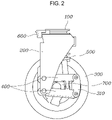
- FIG. 2 is a front view showing the independently driving wheel module according to the embodiment of the present invention.
- FIG. 3 is an enlarged view showing the independently driving wheel module according to the embodiment of the present invention.
- the independently driving wheel module includes: a base frame 100 having an upper end fixed to a coupling surface of a vehicle body F, and having a rotation part 110 coupled to the upper end to be relatively rotatable with respect to the upper end; a connection link 200 of which a first end is integrally coupled to the rotation part 110 of the base frame 100, and a second end has a shape extending downward from the first end thereof; a driving wheel 300 located at a side of the second end of the connection link 200 and coupled to the second end of the connection link 200; and a rotation plate 800 of which an upper surface and a lower surface extend obliquely in misaligned directions, the rotation plate 800 being interposed between the base frame 100 and the vehicle body F so as to be relatively rotatable with respect to the base frame 100 or the vehicle body F.
- the vehicle body F may be a main body frame of a vehicle.
- the vehicle body F may include all equipment that may be equipped with the driving wheel 300, such as robots, transport devices, etc.
- the coupling surface of the vehicle body F may be located at a plurality of locations provided on the vehicle body F.
- the coupling surfaces may be four coupling surfaces located on the front left and right of the vehicle body F and on the rear left and right of the vehicle body F.
- the independently driving wheel module may be separately mounted each corner of the vehicle.
- the base frame 100 is located below the coupling surface of the vehicle body F.
- the upper end of the base frame 100 may be securely fixed to the coupling surface of the vehicle body F.
- the upper end of the base frame 100 may be bolted to the coupling surface of the vehicle body F.
- the base frame 100 may include the rotation part 110 that is coupled to the upper end in a relatively rotatable manner.
- the rotation part 110 may be rotatable on a shaft that extends in a vertical direction or a direction perpendicular to the coupling surface of the vehicle body F.
- the rotation part 110 of the base frame 100 is relatively rotated on the upper end of the base frame 100 coupled to the coupling surface of the vehicle body F. Accordingly, the driving wheel 300 may be steered while being rotated on the vehicle body F.
- connection link 200 may connect the driving wheel 300 to the base frame 100.
- the first end of the connection link 200 is integrally coupled to the rotation part 110 of the base frame 100. As the rotation part 110 is rotated, the first end of the connection link 200 may also be rotated with the rotation part 110.
- the second end of the connection link 200 may extend downward so as to be located at a side of the driving wheel 300.
- the driving wheel 300 is located at the side of the second end of the connection link 200 and may be coupled to the second end of the connection link 200. As described below, the driving wheel 300 includes a separate driving device 700. The driving device 700 may rotate the driving wheel 300 on the second end of the connection link 200.
- the rotation plate 800 may include the upper and lower surfaces that extend obliquely in the misaligned directions.
- the upper surface of the rotation plate 800 may be in planar-contact with the coupling surface of the vehicle body F and the lower surface thereof may be in planar-contact with the upper surface of the base frame 100.
- the rotation plate 800 may be interposed between the base frame 100 and the vehicle body F and may be coupled to the base frame 100 or the vehicle body F in the relatively rotatable manner. Therefore, as the rotation plate 800 having the upper and lower surfaces that are obliquely biased from each other is relatively rotated on the base frame 100 or the vehicle body F, an angle at which the base frame 100 is coupled to the vehicle body F may vary.
- an angle at which the base frame 100 is coupled to the vehicle body F may be adjusted by rotating the rotation plate 800 that has the upper and lower surfaces extending obliquely between the base frame 100 and the vehicle body F.
- the rotation plate 800 is located between the base frame 100 and the vehicle body F and is coupled to the base frame 100 or the vehicle body F in the relatively rotatable manner. While the rotation plate 800 is coupled to the base frame 100 or the vehicle body F in the relatively rotatable manner, the rotation plate 800 may be securely coupled to the base frame 100 to the vehicle body F.
- the rotation plate 800 is interposed between the base frame 100 and the vehicle body F, and is primarily coupled to the base frame 100 or the vehicle body F in the relatively rotatable manner. After angle adjustment is completed by rotation of the rotation plate 800, the rotation plate 800 may be securely coupled to the base frame 100 or the vehicle body F while being in coupled state in the relatively rotatable manner.
- FIG. 4 is an enlarged view showing the rotation plate 800 according to the embodiment of the present invention.
- FIG. 5 is an enlarged view showing the rotation plate 800 and the base frame 100 in a coupled state according to the embodiment of the present invention.
- the rotation plate 800 has a long hole 810 extending along a path that is relatively rotated with respect to the base frame 100.
- the rotation plate 800 may be coupled to the base frame 100 or the vehicle body F in the relatively rotatable manner via the long hole 810.
- the base frame 100 is bolted to the vehicle body F by a bolt extending in a longitudinal direction thereof, and the bolt may extend to penetrate the rotation plate 800 interposed between the base frame 100 and the vehicle body F.
- the bolt may be coupled to the base frame 100 and the vehicle body F while passing through the long hole 810 of the rotation plate 800.
- the rotation plate 800 may be relatively rotatable with respect to the base frame 100 or the vehicle body F along the long hole 810.
- the base frame 100 has a coupling groove 120 that is depressed downward or inward.
- the rotation plate 800 may be fixed by being locked and coupled to the coupling groove 120 while being rotatably coupled to the base frame 100.
- the base frame 100 has the coupling groove 120 that penetrates the based frame or is depressed thereon.
- the rotation plate 800 may be fixed while being locked and coupled to the coupling groove 120.
- the base frame 100 has the coupling groove 120 that is depressed inward of the base frame or depressed downward from the upper surface thereof in contact with the rotation plate 800. As the rotation plate 800 is projected inward of the coupling groove 120 by plastic deformation (caulking, etc.), the rotation plate 800 may be locked and coupled to the coupling groove 120.
- rotation plate 800 is primarily coupled to the base frame 100 or the vehicle body F to be rotatable, the rotation plate 800 may be finally coupled to the base frame 100 or the vehicle body F so as to prevent relative rotation as the rotation plate 800 is plastically deformed to be projected toward the coupling groove 120 of the base frame 100.
- the rotation plate 800 may be formed of a metal material such as aluminum, and the upper and lower surfaces of the rotation plate 800 may be processed in a knurling manner. Accordingly, when the rotation plate 800 is finally coupled to the base frame 100 and the vehicle body F, relative rotation therebetween can be prevented.
- the upper surface of the rotation plate 800 extends parallel to the coupling surface of the vehicle body F and the lower surface thereof extends parallel to the upper surface of the base frame 100.
- the coupling surface of the vehicle body F and the upper surface of the base frame 100 may be inclined obliquely.
- the upper surface and the lower surface of the rotation plate 800 may extend in diagonal directions from each other instead of being parallel to each other.
- the upper surface of the rotation plate 800 may extend parallel to the coupling surface of the vehicle body F to be in planar-contact therewith.
- the lower surface of the rotation plate 800 may extend parallel to the upper surface of the base frame 100 to be in planar contact therewith.
- the upper surface of the base frame 100 diagonally extends in a non-parallel direction to the coupling surface of the vehicle body F, whereby the camber angle or the caster angle of the driving wheel 300 may be generated.
- FIGS. 6 to 7 are views respectively showing the camber angle and the caster angle of the driving wheel 300 according to the embodiment of the present invention.
- the rotation plate 800 may change the camber angle or the caster angle of the driving wheel 300 by being relatively rotated with respect to the base frame 100 or the vehicle body F.
- the rotation plate 800 with the upper and lower surfaces that extend in the diagonal directions from each other is relatively rotated with respect to the base frame 100 or the vehicle body F, the angle at which the base frame 100 is coupled to the coupling surface of the vehicle body F may be adjusted. Therefore, the camber angle and the caster angle of the driving wheel 300 coupled to the base frame 100 may vary at the same time.
- the driving wheel 300 may include a knuckle 310 coupled to the second end of the connection link 200 and a hub rotatably coupled to the knuckle 310.
- the independently driving wheel module may include: the driving device 700 fixed to the knuckle 310 and rotating the hub on the knuckle 310 when the driving device is operated.
- the knuckle 310 is coupled to the second end of the connection link 200, and as described below, the knuckle 310 may be rotatably coupled to the second end of the connection link 200.
- the hub may be rotatably coupled to the knuckle 310, and the hub may be rotated in a grounded state with the ground through a tire or the like.
- the driving device 700 may be an in-wheel motor, and may be securely coupled to the knuckle 310 to apply a rotation force to the hub when the driving device is operated.
- the driving wheel 300 includes the knuckle 310 coupled to the second end of the connection link 200 and the hub rotatably coupled to the knuckle 310.
- the knuckle 310 may be coupled to the second end of the connection link 200 so as to allow relative movement in a vertical direction with respect to the second end of the connection link 200.
- the knuckle 310 may be rotatably coupled to the second end of the connection link 200. As the knuckle 310 is rotatably coupled to the second end of the connection link 200, the knuckle 310 may be relatively moved upward and downward with respect to the second end of the connection link 200.
- the independently driving wheel module may include: a plurality of coupling links 400 that are disposed to be vertically spaced apart from each other, of which each first end is rotatably coupled to the second end of the connection link 200, and of which each second end is rotatably coupled to the knuckle 310.
- the plurality of coupling links 400 extends in a longitudinal direction according to a forward direction in which the driving wheel 300 travels by rotation thereof, and may be disposed to be spaced apart from each other in a vertical direction. Furthermore, the plurality of coupling links 400 is rotatably coupled to, at a first end thereof, to the second end of the connection link 200 while being spaced apart from each other, and the second end of the plurality of the coupling links may be rotatably coupled to the knuckle 310.
- connection link 200 and the knuckle 310 may provide a 4-bar linkage structure due to the plurality of coupling links 400, whereby the knuckle 310 may be moved upward and downward with respect to the second end of the connection link 200.
- the independently driving wheel module may include: a suspension device 500 of which a first end is coupled to the connection link 200 and a second end is connected to the driving wheel 300, the suspension device 500 absorbing vertical vibration of the driving wheel 300.
- the suspension device 500 may be a shock absorber.
- the first end of the suspension device 500 may be securely coupled to the connection link 200 and the second end thereof may be rotatably coupled to the knuckle 310 or the plurality of coupling links 400.
- the second end of the suspension device 500 may penetrate an upper coupling link 400 of the plurality of coupling links 400 and be rotatably coupled to a lower coupling link 400 thereof.
- the independently driving wheel module may include: a steering device 600 of which a first end is securely coupled to the upper end of the base frame 100, the steering device 600 configured to rotate the rotation part 110 or the connection link 200 with respect to the first end thereof.
- the steering device 600 may be a separate motor as the driving device 700.
- the steering device 600 may rotate the rotation part 110 or the connection link 200 with respect to the upper end of the base frame 100 securely coupled to the vehicle body F.
- the steering device 600 is integrally coupled to the rotation part 110 or the connection link 200.
- the steering device 600 may be rotated on the first end thereof fixed to the vehicle body F.
- the first end of the steering device 600 is connected to the upper end of the base frame 100 with a gear, thereby increasing steering torque.
- FIG. 8 is a flowchart showing a mounting method of the independently driving wheel module according to an embodiment of the present invention.
- the mounting method of the independently driving wheel module includes: interposing the rotation plate 800 between the base frame 100 and the vehicle body F in the relative rotatable manner with respect to the base frame 100 or the vehicle body F at S100; relatively rotating the rotation plate 800 with respect to the base frame 100 or the vehicle body F at S300; and securely coupling the rotation plate 800 to the base frame 100 or the vehicle body F at S400.
- the mounting method may include: primarily coupling the base frame 100 to the vehicle body F at S200 so as to prevent relative rotation.
- the rotation plate 800 obliquely inclined may be relatively rotated with respect to the base frame 100 or the vehicle body F so as to change the camber angle or the caster angle of the driving wheel 300.
- the rotation plate 800 may be securely coupled to the base frame 100 or the vehicle body F by being plastically deformed.
Landscapes
- Engineering & Computer Science (AREA)
- Mechanical Engineering (AREA)
- Chemical & Material Sciences (AREA)
- Combustion & Propulsion (AREA)
- Transportation (AREA)
- Vehicle Body Suspensions (AREA)
Abstract
Description
- The present invention relates to an independently driving wheel module and a mounting method thereof and, more particularly, to a driving wheel module configured such that each driving wheel is provided with driving, brake, steering, and suspension devices.
- A new concept in which a driving wheel of a vehicle is modularized and separately mounted is being developed for purpose of improving the freedom of motion of the vehicle and securing battery space in an electric vehicle (EV), or achieving common use of a vehicle platform.
- The new concept independently driving wheel module is assembled to the vehicle body while being provided with driving, brake, steering, and suspension devices and being modularized.
- According to the independently driving wheel module separately assembled, various vehicle motions (for example, zero turning, crab steering, vertical-horizontal traveling, etc.) are possible during driving of a vehicle. A platform can be used in common use and simplified during vehicle development and production.
- However, the independently driving wheel module according to the related art has a problem in that it is difficult to adjust deviation for dynamic geometry during assembly of the driving wheel module to a vehicle body.
- The foregoing is intended merely to aid in the understanding of the background of the present invention, and is not intended to mean that the present invention falls within the purview of the related art that is already known to those skilled in the art.
- This Summary is provided to introduce a selection of concepts in a simplified form that are further described below in the Detailed Description. This Summary is not intended to identify key features or essential features of the claimed subject matter, nor is it intended to be used as an aid in determining the scope of the claimed subject matter.
- In one general aspect, an independently driving wheel module includes: a base frame including an upper end fixed to a coupling surface of a vehicle body, and a rotation part coupled to the upper end of the base frame such that the rotation part is rotatable with respect to the upper end of the base frame; a connection link including a first end integrally coupled to the rotation part, and a second end having a shape extending downward from the first end of the connection link; a driving wheel disposed at a side of the second end of the connection link and coupled to the second end of the connection link; and a rotation plate including an upper surface and a lower surface extending obliquely in misaligned directions, the rotation plate being interposed between the base frame and the vehicle body so as to be rotatable with respect to the base frame or the vehicle body.
- The rotation plate may be securely coupled to the base frame or the vehicle body such that the rotation plate is rotatable with respect to the base frame or the vehicle body.
- The rotation plate may further include an elongated hole extending along a path in which the rotation plate is rotatable with respect to the base frame. The rotation plate may be coupled to the base frame or the vehicle body via the elongated hole.
- The base frame may further include a coupling groove that is depressed downward or inward in the base frame. The rotation plate may be fixed by being locked and coupled to the coupling groove while being rotatably coupled to the base frame.
- The upper surface of the rotation plate may extend parallel to the coupling surface of the vehicle body and the lower surface of the rotation plate may extend parallel to an upper surface of the base frame. The coupling surface of the vehicle body and the upper surface of the base frame may be inclined obliquely to each other.
- A camber angle or a caster angle of the driving wheel may vary when the rotation plate is rotated with respect to the base frame or the vehicle body.
- The driving wheel may include a knuckle coupled to the second end of the connection link and a hub rotatably coupled to the knuckle. The independently driving wheel module may further include a driving device fixed to the knuckle and operable to rotate the hub on the knuckle.
- The driving wheel may include a knuckle coupled to the second end of the connection link and a hub rotatably coupled to the knuckle. The knuckle may be coupled to the second end of the connection link so as to allow relative movement of the knuckle in a vertical direction with respect to the connection link.
- The independently driving wheel module may further include coupling links disposed to be vertically spaced apart from each other, the coupling links including respective first ends rotatably coupled to the second end of the connection link, and respective second ends rotatably coupled to the knuckle.
- The independently driving wheel module may further include a suspension device including a first end coupled to the connection link and a second end connected to the driving wheel, the suspension device being configured to absorb vertical vibration of the driving wheel.
- The independently driving wheel module may further include: a steering device including a first end securely coupled to the upper end of the base frame, the steering device being configured to rotate the rotation part or the connection link on the first end of the steering device as a center of rotation.
- In another general aspect, a method of mounting an independently driving wheel module includes: interposing a rotation plate between a base frame and a vehicle body and fixing an upper end of the base frame to a coupling surface of the vehicle body, such that the rotation plate is rotatable with respect to the base frame or the vehicle body; rotating the rotation plate with respect to the base frame or the vehicle body; and securely coupling the rotation plate to the base frame or the vehicle body. The base frame includes a rotation part coupled to the upper end of the base frame such that the rotation part is rotatable with respect to the upper end of the base frame. The rotation plate includes an upper surface and a lower surface extending obliquely in misaligned directions. The independently driving wheel module comprises: the rotation plate; the base frame; a connection link including a first end integrally coupled to the rotation part, and a second end having a shape extending downward from the first end of the connection link; and a driving wheel disposed at a side of the second end of the connection link and coupled to the second end of the connection link.
- The method may further include: after the interposing the rotation plate, primarily coupling the base frame to the vehicle body so as to prevent rotation of the base frame with respect to the vehicle body.
- In the rotating of the rotation plate, the rotation plate may be rotated with respect to the base frame or the vehicle body so as to change a camber angle or a caster angle of the driving wheel.
- The securely coupling of the rotation plate may include securely coupling the rotation plate to the base frame or the vehicle body by plastically deforming the rotation plate.
- Other features and aspects will be apparent from the following detailed description, the drawings, and the claims.
- The above and other objectives, features, and other advantages of the present invention will be more clearly understood from the following detailed description when taken in conjunction with the accompanying drawings, in which:
-
FIG. 1 is a perspective view showing an independently driving wheel module according to an embodiment of the present invention. -
FIG. 2 is a front view showing the independently driving wheel module according to the embodiment of the present invention. -
FIG. 3 is an enlarged view showing the independently driving wheel module according to the embodiment of the present invention. -
FIG. 4 is an enlarged view showing a rotation plate according to the embodiment of the present invention. -
FIG. 5 is an enlarged view showing the rotation plate and a base frame in a coupled state according to the embodiment of the present invention. -
FIGS. 6 to 7 are views respectively showing a camber angle and a caster angle of the driving wheel according to the embodiment of the present invention. -
FIG. 8 is a flowchart showing a mounting method of the independently driving wheel module according to an embodiment of the present invention. - In the following description, the structural or functional description specified to exemplary embodiments according to the concept of the present invention is intended to describe the exemplary embodiments, so it should be understood that the present invention may be variously embodied, without being limited to the exemplary embodiments.
- Embodiments described herein may be changed in various ways and various shapes, so specific embodiments are shown in the drawings and will be described in detail in this specification. However, it should be understood that the exemplary embodiments according to the concept of the present invention are not limited to the embodiments which will be described hereinbelow with reference to the accompanying drawings, but all of modifications, equivalents, and substitutions are included in the scope and spirit of the invention.
- It will be understood that, although the terms first and/or second, etc. may be used herein to describe various elements, these elements should not be limited by these terms. These terms are only used to distinguish one element, from another element. For instance, a first element discussed below could be termed a second element without departing from the teachings of the present invention. Similarly, the second element could also be termed the first element.
- It is to be understood that when one element is referred to as being "connected to" or "coupled to" another element, it may be connected directly to or coupled directly to another element or be connected to or coupled to another element, having the other element intervening therebetween. On the other hand, it is to be understood that when one element is referred to as being "connected directly to" or "coupled directly to" another element, it may be connected to or coupled to another element without the other element intervening therebetween. Further, the terms used herein to describe a relationship between elements, that is, "between", "directly between", "adjacent" or "directly adjacent" should be construed in the same manner.
- The terminology used herein is for the purpose of describing particular embodiments only and is not intended to limit the present invention. Singular forms are intended to include plural forms unless the context clearly indicates otherwise. It will be further understood that the terms "comprises" or "have" used in this specification, specify the presence of stated features, steps, operations, components, parts, or a combination thereof, but do not preclude the presence or addition of one or more other features, numerals, steps, operations, components, parts, or a combination thereof.
- Unless otherwise defined, all terms including technical and scientific terms used herein have the same meaning as commonly understood by those skilled in the art to which the present invention belongs. It must be understood that the terms defined by the dictionary are identical with the meanings within the context of the related art, and they should not be ideally or excessively formally defined unless the context clearly dictates otherwise.
- Hereinbelow, preferred embodiments of the present invention will be described in detail with reference to accompanying drawings. Like reference numerals given in the drawings indicate like components.
-
FIG. 1 is a perspective view showing an independently driving wheel module according to an embodiment of the present invention.FIG. 2 is a front view showing the independently driving wheel module according to the embodiment of the present invention.FIG. 3 is an enlarged view showing the independently driving wheel module according to the embodiment of the present invention. - Referring to
FIGS. 1 to 3 , the independently driving wheel module according to the embodiment of the present invention includes: abase frame 100 having an upper end fixed to a coupling surface of a vehicle body F, and having arotation part 110 coupled to the upper end to be relatively rotatable with respect to the upper end; aconnection link 200 of which a first end is integrally coupled to therotation part 110 of thebase frame 100, and a second end has a shape extending downward from the first end thereof; adriving wheel 300 located at a side of the second end of theconnection link 200 and coupled to the second end of theconnection link 200; and arotation plate 800 of which an upper surface and a lower surface extend obliquely in misaligned directions, therotation plate 800 being interposed between thebase frame 100 and the vehicle body F so as to be relatively rotatable with respect to thebase frame 100 or the vehicle body F. - The vehicle body F may be a main body frame of a vehicle. As another embodiment, the vehicle body F may include all equipment that may be equipped with the
driving wheel 300, such as robots, transport devices, etc. - The coupling surface of the vehicle body F may be located at a plurality of locations provided on the vehicle body F. Specifically, the coupling surfaces may be four coupling surfaces located on the front left and right of the vehicle body F and on the rear left and right of the vehicle body F. According to the embodiment of the present invention, the independently driving wheel module may be separately mounted each corner of the vehicle.
- The
base frame 100 is located below the coupling surface of the vehicle body F. The upper end of thebase frame 100 may be securely fixed to the coupling surface of the vehicle body F. As an embodiment, the upper end of thebase frame 100 may be bolted to the coupling surface of the vehicle body F. - The
base frame 100 may include therotation part 110 that is coupled to the upper end in a relatively rotatable manner. As the embodiment, therotation part 110 may be rotatable on a shaft that extends in a vertical direction or a direction perpendicular to the coupling surface of the vehicle body F. - The
rotation part 110 of thebase frame 100 is relatively rotated on the upper end of thebase frame 100 coupled to the coupling surface of the vehicle body F. Accordingly, thedriving wheel 300 may be steered while being rotated on the vehicle body F. - The
connection link 200 may connect thedriving wheel 300 to thebase frame 100. The first end of theconnection link 200 is integrally coupled to therotation part 110 of thebase frame 100. As therotation part 110 is rotated, the first end of theconnection link 200 may also be rotated with therotation part 110. The second end of theconnection link 200 may extend downward so as to be located at a side of thedriving wheel 300. - The
driving wheel 300 is located at the side of the second end of theconnection link 200 and may be coupled to the second end of theconnection link 200. As described below, thedriving wheel 300 includes aseparate driving device 700. Thedriving device 700 may rotate thedriving wheel 300 on the second end of theconnection link 200. - The
rotation plate 800 may include the upper and lower surfaces that extend obliquely in the misaligned directions. The upper surface of therotation plate 800 may be in planar-contact with the coupling surface of the vehicle body F and the lower surface thereof may be in planar-contact with the upper surface of thebase frame 100. - The
rotation plate 800 may be interposed between thebase frame 100 and the vehicle body F and may be coupled to thebase frame 100 or the vehicle body F in the relatively rotatable manner. Therefore, as therotation plate 800 having the upper and lower surfaces that are obliquely biased from each other is relatively rotated on thebase frame 100 or the vehicle body F, an angle at which thebase frame 100 is coupled to the vehicle body F may vary. - With the structure of the
rotation plate 800, while the independently driving wheel module is primarily assembled to the vehicle body F, a camber angle and a caster angle may be adjusted. - Therefore, an angle at which the
base frame 100 is coupled to the vehicle body F may be adjusted by rotating therotation plate 800 that has the upper and lower surfaces extending obliquely between thebase frame 100 and the vehicle body F. - The
rotation plate 800 is located between thebase frame 100 and the vehicle body F and is coupled to thebase frame 100 or the vehicle body F in the relatively rotatable manner. While therotation plate 800 is coupled to thebase frame 100 or the vehicle body F in the relatively rotatable manner, therotation plate 800 may be securely coupled to thebase frame 100 to the vehicle body F. - In detail, the
rotation plate 800 is interposed between thebase frame 100 and the vehicle body F, and is primarily coupled to thebase frame 100 or the vehicle body F in the relatively rotatable manner. After angle adjustment is completed by rotation of therotation plate 800, therotation plate 800 may be securely coupled to thebase frame 100 or the vehicle body F while being in coupled state in the relatively rotatable manner. -
FIG. 4 is an enlarged view showing therotation plate 800 according to the embodiment of the present invention.FIG. 5 is an enlarged view showing therotation plate 800 and thebase frame 100 in a coupled state according to the embodiment of the present invention. - Referring to
FIGS. 4 and5 , therotation plate 800 has along hole 810 extending along a path that is relatively rotated with respect to thebase frame 100. Therotation plate 800 may be coupled to thebase frame 100 or the vehicle body F in the relatively rotatable manner via thelong hole 810. - As the embodiment, the
base frame 100 is bolted to the vehicle body F by a bolt extending in a longitudinal direction thereof, and the bolt may extend to penetrate therotation plate 800 interposed between thebase frame 100 and the vehicle body F. Specifically, the bolt may be coupled to thebase frame 100 and the vehicle body F while passing through thelong hole 810 of therotation plate 800. Therotation plate 800 may be relatively rotatable with respect to thebase frame 100 or the vehicle body F along thelong hole 810. - In addition, the
base frame 100 has acoupling groove 120 that is depressed downward or inward. Therotation plate 800 may be fixed by being locked and coupled to thecoupling groove 120 while being rotatably coupled to thebase frame 100. - The
base frame 100 has thecoupling groove 120 that penetrates the based frame or is depressed thereon. Therotation plate 800 may be fixed while being locked and coupled to thecoupling groove 120. - As an embodiment, the
base frame 100 has thecoupling groove 120 that is depressed inward of the base frame or depressed downward from the upper surface thereof in contact with therotation plate 800. As therotation plate 800 is projected inward of thecoupling groove 120 by plastic deformation (caulking, etc.), therotation plate 800 may be locked and coupled to thecoupling groove 120. - While the
rotation plate 800 is primarily coupled to thebase frame 100 or the vehicle body F to be rotatable, therotation plate 800 may be finally coupled to thebase frame 100 or the vehicle body F so as to prevent relative rotation as therotation plate 800 is plastically deformed to be projected toward thecoupling groove 120 of thebase frame 100. - As an embodiment, the
rotation plate 800 may be formed of a metal material such as aluminum, and the upper and lower surfaces of therotation plate 800 may be processed in a knurling manner. Accordingly, when therotation plate 800 is finally coupled to thebase frame 100 and the vehicle body F, relative rotation therebetween can be prevented. - The upper surface of the
rotation plate 800 extends parallel to the coupling surface of the vehicle body F and the lower surface thereof extends parallel to the upper surface of thebase frame 100. The coupling surface of the vehicle body F and the upper surface of thebase frame 100 may be inclined obliquely. - Specifically, the upper surface and the lower surface of the
rotation plate 800 may extend in diagonal directions from each other instead of being parallel to each other. The upper surface of therotation plate 800 may extend parallel to the coupling surface of the vehicle body F to be in planar-contact therewith. The lower surface of therotation plate 800 may extend parallel to the upper surface of thebase frame 100 to be in planar contact therewith. - Accordingly, the upper surface of the
base frame 100 diagonally extends in a non-parallel direction to the coupling surface of the vehicle body F, whereby the camber angle or the caster angle of thedriving wheel 300 may be generated. -
FIGS. 6 to 7 are views respectively showing the camber angle and the caster angle of thedriving wheel 300 according to the embodiment of the present invention. - Referring to
FIGS. 6 and7 , therotation plate 800 may change the camber angle or the caster angle of thedriving wheel 300 by being relatively rotated with respect to thebase frame 100 or the vehicle body F. - As an embodiment, as the
rotation plate 800 with the upper and lower surfaces that extend in the diagonal directions from each other is relatively rotated with respect to thebase frame 100 or the vehicle body F, the angle at which thebase frame 100 is coupled to the coupling surface of the vehicle body F may be adjusted. Therefore, the camber angle and the caster angle of thedriving wheel 300 coupled to thebase frame 100 may vary at the same time. - The
driving wheel 300 may include aknuckle 310 coupled to the second end of theconnection link 200 and a hub rotatably coupled to theknuckle 310. The independently driving wheel module may include: the drivingdevice 700 fixed to theknuckle 310 and rotating the hub on theknuckle 310 when the driving device is operated. - The
knuckle 310 is coupled to the second end of theconnection link 200, and as described below, theknuckle 310 may be rotatably coupled to the second end of theconnection link 200. The hub may be rotatably coupled to theknuckle 310, and the hub may be rotated in a grounded state with the ground through a tire or the like. - The
driving device 700 may be an in-wheel motor, and may be securely coupled to theknuckle 310 to apply a rotation force to the hub when the driving device is operated. - The
driving wheel 300 includes theknuckle 310 coupled to the second end of theconnection link 200 and the hub rotatably coupled to theknuckle 310. Theknuckle 310 may be coupled to the second end of theconnection link 200 so as to allow relative movement in a vertical direction with respect to the second end of theconnection link 200. - The
knuckle 310 may be rotatably coupled to the second end of theconnection link 200. As theknuckle 310 is rotatably coupled to the second end of theconnection link 200, theknuckle 310 may be relatively moved upward and downward with respect to the second end of theconnection link 200. - More specifically, the independently driving wheel module may include: a plurality of
coupling links 400 that are disposed to be vertically spaced apart from each other, of which each first end is rotatably coupled to the second end of theconnection link 200, and of which each second end is rotatably coupled to theknuckle 310. - The plurality of
coupling links 400 extends in a longitudinal direction according to a forward direction in which thedriving wheel 300 travels by rotation thereof, and may be disposed to be spaced apart from each other in a vertical direction. Furthermore, the plurality ofcoupling links 400 is rotatably coupled to, at a first end thereof, to the second end of theconnection link 200 while being spaced apart from each other, and the second end of the plurality of the coupling links may be rotatably coupled to theknuckle 310. - The
connection link 200 and theknuckle 310 may provide a 4-bar linkage structure due to the plurality ofcoupling links 400, whereby theknuckle 310 may be moved upward and downward with respect to the second end of theconnection link 200. - The independently driving wheel module may include: a
suspension device 500 of which a first end is coupled to theconnection link 200 and a second end is connected to thedriving wheel 300, thesuspension device 500 absorbing vertical vibration of thedriving wheel 300. - The
suspension device 500 may be a shock absorber. The first end of thesuspension device 500 may be securely coupled to theconnection link 200 and the second end thereof may be rotatably coupled to theknuckle 310 or the plurality ofcoupling links 400. - As an embodiment, the second end of the
suspension device 500 may penetrate anupper coupling link 400 of the plurality ofcoupling links 400 and be rotatably coupled to alower coupling link 400 thereof. - The independently driving wheel module may include: a
steering device 600 of which a first end is securely coupled to the upper end of thebase frame 100, thesteering device 600 configured to rotate therotation part 110 or theconnection link 200 with respect to the first end thereof. - The
steering device 600 may be a separate motor as thedriving device 700. Thesteering device 600 may rotate therotation part 110 or theconnection link 200 with respect to the upper end of thebase frame 100 securely coupled to the vehicle body F. Thesteering device 600 is integrally coupled to therotation part 110 or theconnection link 200. Thesteering device 600 may be rotated on the first end thereof fixed to the vehicle body F. - Specifically, the first end of the
steering device 600 is connected to the upper end of thebase frame 100 with a gear, thereby increasing steering torque. -
FIG. 8 is a flowchart showing a mounting method of the independently driving wheel module according to an embodiment of the present invention. - Referring to
FIG. 8 , as a method of mounting the independently driving wheel module, the mounting method of the independently driving wheel module according to an embodiment of the present invention includes: interposing therotation plate 800 between thebase frame 100 and the vehicle body F in the relative rotatable manner with respect to thebase frame 100 or the vehicle body F at S100; relatively rotating therotation plate 800 with respect to thebase frame 100 or the vehicle body F at S300; and securely coupling therotation plate 800 to thebase frame 100 or the vehicle body F at S400. - After the interposing the
rotation plate 800 at S100, the mounting method may include: primarily coupling thebase frame 100 to the vehicle body F at S200 so as to prevent relative rotation. - In the relatively rotating the
rotation plate 800 at S300, therotation plate 800 obliquely inclined may be relatively rotated with respect to thebase frame 100 or the vehicle body F so as to change the camber angle or the caster angle of thedriving wheel 300. - In the securely coupling the
rotation plate 800 at S400, therotation plate 800 may be securely coupled to thebase frame 100 or the vehicle body F by being plastically deformed. - Although the preferred embodiments of the present invention have been disclosed for illustrative purposes, those skilled in the art will appreciate that various modifications, additions and substitutions are possible, without departing from the spirit and scope of the present invention.
Claims (15)
- An independently driving wheel module, comprising:a base frame including an upper end fixed to a coupling surface of a vehicle body, and a rotation part coupled to the upper end of the base frame such that the rotation part is rotatable with respect to the upper end of the base frame;a connection link including a first end integrally coupled to the rotation part, and a second end having a shape extending downward from the first end of the connection link;a driving wheel disposed at a side of the second end of the connection link and coupled to the second end of the connection link; anda rotation plate including an upper surface and a lower surface extending obliquely in misaligned directions, the rotation plate being interposed between the base frame and the vehicle body so as to be rotatable with respect to the base frame or the vehicle body.
- The independently driving wheel module of claim 1, wherein the rotation plate is securely coupled to the base frame or the vehicle body such that the rotation plate is rotatable with respect to the base frame or the vehicle body.
- The independently driving wheel module of claim 2, wherein the rotation plate further includes an elongated hole extending along a path in which the rotation plate is rotatable with respect to the base frame, and
wherein the rotation plate is coupled to the base frame or the vehicle body via the elongated hole. - The independently driving wheel module of claim 2, wherein the base frame further includes a coupling groove that is depressed downward or inward in the base frame, and
wherein the rotation plate is fixed by being locked and coupled to the coupling groove while being rotatably coupled to the base frame. - The independently driving wheel module of claim 1, wherein the upper surface of the rotation plate extends parallel to the coupling surface of the vehicle body and the lower surface of the rotation plate extends parallel to an upper surface of the base frame, and
wherein the coupling surface of the vehicle body and the upper surface of the base frame are inclined obliquely to each other. - The independently driving wheel module of claim 1, wherein a camber angle or a caster angle of the driving wheel varies when the rotation plate is rotated with respect to the base frame or the vehicle body.
- The independently driving wheel module of claim 1, wherein the driving wheel comprises a knuckle coupled to the second end of the connection link and a hub rotatably coupled to the knuckle, and
wherein the independently driving wheel module further comprises a driving device fixed to the knuckle and operable to rotate the hub on the knuckle. - The independently driving wheel module of claim 1, wherein the driving wheel comprises a knuckle coupled to the second end of the connection link and a hub rotatably coupled to the knuckle, and
wherein the knuckle is coupled to the second end of the connection link so as to allow relative movement of the knuckle in a vertical direction with respect to the connection link. - The independently driving wheel module of claim 8, further comprising:
coupling links disposed to be vertically spaced apart from each other, the coupling links including respective first ends rotatably coupled to the second end of the connection link, and respective second ends rotatably coupled to the knuckle. - The independently driving wheel module of claim 1, further comprising:
a suspension device including a first end coupled to the connection link and a second end connected to the driving wheel, the suspension device being configured to absorb vertical vibration of the driving wheel. - The independently driving wheel module of claim 1, further comprising:
a steering device including a first end securely coupled to the upper end of the base frame, the steering device being configured to rotate the rotation part or the connection link on the first end of the steering device as a center of rotation. - A method of mounting an independently driving wheel module, the method comprising:interposing a rotation plate between a base frame and a vehicle body and fixing an upper end of the base frame to a coupling surface of the vehicle body, such that the rotation plate is rotatable with respect to the base frame or the vehicle body;rotating the rotation plate with respect to the base frame or the vehicle body; andsecurely coupling the rotation plate to the base frame or the vehicle body,wherein the base frame includes a rotation part coupled to the upper end of the base frame such that the rotation part is rotatable with respect to the upper end of the base frame,wherein the rotation plate includes an upper surface and a lower surface extending obliquely in misaligned directions, andwherein the independently driving wheel module comprises:the rotation plate;the base frame;a connection link including a first end integrally coupled to the rotation part, and a second end having a shape extending downward from the first end of the connection link; anda driving wheel disposed at a side of the second end of the connection link and coupled to the second end of the connection link.
- The method of claim 12, further comprising:
after the interposing the rotation plate, primarily coupling the base frame to the vehicle body so as to prevent rotation of the base frame with respect to the vehicle body. - The method of claim 12, wherein, in the rotating of the rotation plate, the rotation plate is rotated with respect to the base frame or the vehicle body so as to change a camber angle or a caster angle of the driving wheel.
- The method of claim 12, wherein the securely coupling of the rotation plate comprises securely coupling the rotation plate to the base frame or the vehicle body by plastically deforming the rotation plate.
Applications Claiming Priority (1)
| Application Number | Priority Date | Filing Date | Title |
|---|---|---|---|
| KR1020200153702A KR20220067219A (en) | 2020-11-17 | 2020-11-17 | Independently driving wheel module and mounting method thereof |
Publications (2)
| Publication Number | Publication Date |
|---|---|
| EP4000970A1 true EP4000970A1 (en) | 2022-05-25 |
| EP4000970B1 EP4000970B1 (en) | 2023-08-16 |
Family
ID=78695487
Family Applications (1)
| Application Number | Title | Priority Date | Filing Date |
|---|---|---|---|
| EP21207238.3A Active EP4000970B1 (en) | 2020-11-17 | 2021-11-09 | Vehicle and independently driving wheel module and mounting method thereof |
Country Status (4)
| Country | Link |
|---|---|
| US (2) | US11577783B2 (en) |
| EP (1) | EP4000970B1 (en) |
| KR (1) | KR20220067219A (en) |
| CN (1) | CN114506183B (en) |
Cited By (2)
| Publication number | Priority date | Publication date | Assignee | Title |
|---|---|---|---|---|
| EP4183665A1 (en) * | 2021-11-23 | 2023-05-24 | Hyundai Mobis Co., Ltd. | Corner module apparatus for vehicle |
| EP4286182A1 (en) * | 2022-06-03 | 2023-12-06 | Hyundai Mobis Co., Ltd. | Corner module apparatus for vehicle |
Families Citing this family (2)
| Publication number | Priority date | Publication date | Assignee | Title |
|---|---|---|---|---|
| KR20220067219A (en) * | 2020-11-17 | 2022-05-24 | 현대모비스 주식회사 | Independently driving wheel module and mounting method thereof |
| US20240075780A1 (en) * | 2022-09-01 | 2024-03-07 | Aptera Motors Corp. | Rear suspension for vehicle having improved swing arm |
Citations (4)
| Publication number | Priority date | Publication date | Assignee | Title |
|---|---|---|---|---|
| JP2002211201A (en) * | 2001-01-12 | 2002-07-31 | Kaneda Kikai Seisakusho Ltd | Automated guided vehicle |
| WO2011147648A1 (en) * | 2010-05-28 | 2011-12-01 | John Victor Gano | Omni-directional wheel assembly and omni-directional vehicle |
| WO2013127471A1 (en) * | 2012-02-27 | 2013-09-06 | John Victor Gano | Integrated system of independently-variable multi -wheel steering and road contact geometry |
| WO2020145166A1 (en) * | 2019-01-08 | 2020-07-16 | 株式会社Fomm | Suspension unit and vehicle |
Family Cites Families (25)
| Publication number | Priority date | Publication date | Assignee | Title |
|---|---|---|---|---|
| US4418938A (en) * | 1981-09-21 | 1983-12-06 | General Motors Corporation | Vehicle strut suspension with camber adjustment |
| JP3072479B2 (en) * | 1997-06-10 | 2000-07-31 | 丸石自転車株式会社 | wheelchair |
| US5826894A (en) * | 1997-11-20 | 1998-10-27 | Chrysler Corporation | Alignment cam position limiter |
| US6557872B1 (en) * | 2000-10-31 | 2003-05-06 | Ingalls Engineering Company, Inc. | Replacement apparatus providing selectable camber/caster correction |
| US7607668B2 (en) * | 2007-06-08 | 2009-10-27 | Maximum Motorsports | Caster-camber plate assemblies |
| US8075005B1 (en) * | 2008-10-06 | 2011-12-13 | Stempf Automotive Industries, Inc. | Wheel alignment apparatus |
| KR101448761B1 (en) * | 2013-08-20 | 2014-10-08 | 현대자동차 주식회사 | Caster active geometry control system |
| US8820759B1 (en) * | 2013-10-01 | 2014-09-02 | Brian Croutcher | Plates allowing adjustment of caster and camber |
| JP6640240B2 (en) * | 2015-03-13 | 2020-02-05 | サーメ・ドイツ−ファール・イタリア・エス.ピー.エー.SAME DEUTZ−FAHR ITALIA S.p.A | Single suspension wheel steering system with rotation sensor device |
| FR3042463B1 (en) * | 2015-10-19 | 2018-07-13 | Poclain Hydraulics Industrie | DEVICE FOR ROTATING A WHEEL OF A ROLLING MACHINE |
| DE102016203984A1 (en) * | 2016-03-10 | 2017-09-14 | Thyssenkrupp Ag | Wheel steering assembly for motor vehicles with single-wheel steering |
| DE102016209590A1 (en) * | 2016-06-01 | 2017-12-07 | Thyssenkrupp Ag | Strut bearing for supporting a shock absorber on a motor vehicle body and a method for adjusting suspension of motor vehicles |
| CN107160963B (en) * | 2017-05-04 | 2020-08-21 | 大陆智源科技(北京)有限公司 | Wheeled motion chassis |
| CN207141175U (en) * | 2017-06-09 | 2018-03-27 | 哈尔滨理工大学 | A kind of wheeled sufficient end device of hospital's crusing robot |
| DE102018107358A1 (en) | 2018-03-28 | 2019-10-02 | Schaeffler Technologies AG & Co. KG | Wheel module for a motor vehicle |
| DE102018128060A1 (en) * | 2018-11-09 | 2020-05-14 | Schaeffler Technologies AG & Co. KG | Steering device for motor vehicle steering |
| JP2020111270A (en) * | 2019-01-16 | 2020-07-27 | トヨタ自動車株式会社 | Steering device, and vehicular wheel arrangement module provided with the same |
| DE102019106839A1 (en) * | 2019-03-18 | 2020-09-24 | Schaeffler Technologies AG & Co. KG | Wheel module |
| US10988176B2 (en) * | 2019-05-17 | 2021-04-27 | GM Global Technology Operations LLC | Component alignment system |
| JP7339930B2 (en) * | 2020-08-19 | 2023-09-06 | 本田技研工業株式会社 | steering gear |
| US11718139B2 (en) * | 2020-10-07 | 2023-08-08 | Hyundai Mobis Co., Ltd. | System and method for controlling vehicle |
| KR20220067219A (en) * | 2020-11-17 | 2022-05-24 | 현대모비스 주식회사 | Independently driving wheel module and mounting method thereof |
| EP4019310B1 (en) * | 2020-12-28 | 2023-09-27 | Hyundai Mobis Co., Ltd. | Independent drive module |
| KR20220129934A (en) * | 2021-03-17 | 2022-09-26 | 현대모비스 주식회사 | In-wheel drive module of mobility |
| KR20230036598A (en) * | 2021-09-06 | 2023-03-15 | 현대자동차주식회사 | Suspension structure of vehicle for skateboard flatform |
-
2020
- 2020-11-17 KR KR1020200153702A patent/KR20220067219A/en active Search and Examination
-
2021
- 2021-11-05 US US17/519,856 patent/US11577783B2/en active Active
- 2021-11-09 EP EP21207238.3A patent/EP4000970B1/en active Active
- 2021-11-17 CN CN202111361536.2A patent/CN114506183B/en active Active
-
2023
- 2023-01-04 US US18/093,040 patent/US11851103B2/en active Active
Patent Citations (5)
| Publication number | Priority date | Publication date | Assignee | Title |
|---|---|---|---|---|
| JP2002211201A (en) * | 2001-01-12 | 2002-07-31 | Kaneda Kikai Seisakusho Ltd | Automated guided vehicle |
| WO2011147648A1 (en) * | 2010-05-28 | 2011-12-01 | John Victor Gano | Omni-directional wheel assembly and omni-directional vehicle |
| WO2013127471A1 (en) * | 2012-02-27 | 2013-09-06 | John Victor Gano | Integrated system of independently-variable multi -wheel steering and road contact geometry |
| WO2020145166A1 (en) * | 2019-01-08 | 2020-07-16 | 株式会社Fomm | Suspension unit and vehicle |
| EP3909831A1 (en) * | 2019-01-08 | 2021-11-17 | Fomm Corporation | Suspension unit and vehicle |
Cited By (2)
| Publication number | Priority date | Publication date | Assignee | Title |
|---|---|---|---|---|
| EP4183665A1 (en) * | 2021-11-23 | 2023-05-24 | Hyundai Mobis Co., Ltd. | Corner module apparatus for vehicle |
| EP4286182A1 (en) * | 2022-06-03 | 2023-12-06 | Hyundai Mobis Co., Ltd. | Corner module apparatus for vehicle |
Also Published As
| Publication number | Publication date |
|---|---|
| EP4000970B1 (en) | 2023-08-16 |
| US20230143749A1 (en) | 2023-05-11 |
| KR20220067219A (en) | 2022-05-24 |
| CN114506183A (en) | 2022-05-17 |
| CN114506183B (en) | 2023-07-18 |
| US11577783B2 (en) | 2023-02-14 |
| US11851103B2 (en) | 2023-12-26 |
| US20220153348A1 (en) | 2022-05-19 |
Similar Documents
| Publication | Publication Date | Title |
|---|---|---|
| EP4000970A1 (en) | Independently driving wheel module and mounting method thereof | |
| JP6760198B2 (en) | Non-steering drive wheel suspension device with built-in in-wheel motor | |
| US9174505B2 (en) | Vehicle independent suspension | |
| EP3398797B1 (en) | Automatic tilting vehicle | |
| US20160068195A1 (en) | Battery arrangement in a two-track vehicle | |
| CN112124427B (en) | Vehicle structure of frame type vehicle | |
| WO2022134087A1 (en) | Suspension structure, angle module system and motor vehicle | |
| US20230051754A1 (en) | Independent corner module | |
| CN111448085A (en) | Upper arm structure of suspension device | |
| US5887896A (en) | Reinforced front suspension structure of motor vehicle | |
| JPH11222153A (en) | Front wheel suspension device of automobile | |
| US7052024B2 (en) | Suspension assembly applicable to both manual and power steering systems | |
| CN114312183B (en) | Macpherson suspension of front steering gear and automobile | |
| KR20210070415A (en) | Torsion beam axle rear suspension with in-wheel motor | |
| US10086666B2 (en) | Coupling structure for vehicle chassis members | |
| GB2339175A (en) | A rear axle for industrial vehicles | |
| CN118024801A (en) | Steering angle module and vehicle chassis | |
| CN218021085U (en) | Double-fork arm suspension structure and vehicle | |
| JPS6332048Y2 (en) | ||
| JP2005225258A (en) | Plate spring type axle device | |
| JP2813888B2 (en) | Automotive wheel suspension | |
| WO2021099516A1 (en) | A wheel arch and wheel arch assembly | |
| CN118024797A (en) | Steering angle module | |
| KR100498697B1 (en) | Torsion beam type suspension | |
| GB2577400A (en) | Crash Structure |
Legal Events
| Date | Code | Title | Description |
|---|---|---|---|
| PUAI | Public reference made under article 153(3) epc to a published international application that has entered the european phase |
Free format text: ORIGINAL CODE: 0009012 |
|
| STAA | Information on the status of an ep patent application or granted ep patent |
Free format text: STATUS: REQUEST FOR EXAMINATION WAS MADE |
|
| 17P | Request for examination filed |
Effective date: 20211109 |
|
| AK | Designated contracting states |
Kind code of ref document: A1 Designated state(s): AL AT BE BG CH CY CZ DE DK EE ES FI FR GB GR HR HU IE IS IT LI LT LU LV MC MK MT NL NO PL PT RO RS SE SI SK SM TR |
|
| RBV | Designated contracting states (corrected) |
Designated state(s): AL AT BE BG CH CY CZ DE DK EE ES FI FR GB GR HR HU IE IS IT LI LT LU LV MC MK MT NL NO PL PT RO RS SE SI SK SM TR |
|
| RIC1 | Information provided on ipc code assigned before grant |
Ipc: B62D 7/15 20060101ALI20230130BHEP Ipc: B62D 7/06 20060101ALI20230130BHEP Ipc: B62D 5/04 20060101ALI20230130BHEP Ipc: B60G 3/01 20060101ALI20230130BHEP Ipc: B62D 17/00 20060101ALI20230130BHEP Ipc: B60G 7/00 20060101ALI20230130BHEP Ipc: B60G 7/02 20060101ALI20230130BHEP Ipc: B60G 3/20 20060101AFI20230130BHEP |
|
| GRAP | Despatch of communication of intention to grant a patent |
Free format text: ORIGINAL CODE: EPIDOSNIGR1 |
|
| STAA | Information on the status of an ep patent application or granted ep patent |
Free format text: STATUS: GRANT OF PATENT IS INTENDED |
|
| INTG | Intention to grant announced |
Effective date: 20230313 |
|
| GRAS | Grant fee paid |
Free format text: ORIGINAL CODE: EPIDOSNIGR3 |
|
| GRAA | (expected) grant |
Free format text: ORIGINAL CODE: 0009210 |
|
| STAA | Information on the status of an ep patent application or granted ep patent |
Free format text: STATUS: THE PATENT HAS BEEN GRANTED |
|
| AK | Designated contracting states |
Kind code of ref document: B1 Designated state(s): AL AT BE BG CH CY CZ DE DK EE ES FI FR GB GR HR HU IE IS IT LI LT LU LV MC MK MT NL NO PL PT RO RS SE SI SK SM TR |
|
| REG | Reference to a national code |
Ref country code: CH Ref legal event code: EP |
|
| REG | Reference to a national code |
Ref country code: DE Ref legal event code: R096 Ref document number: 602021004319 Country of ref document: DE |
|
| REG | Reference to a national code |
Ref country code: IE Ref legal event code: FG4D |
|
| P01 | Opt-out of the competence of the unified patent court (upc) registered |
Effective date: 20230922 |
|
| PGFP | Annual fee paid to national office [announced via postgrant information from national office to epo] |
Ref country code: FR Payment date: 20230922 Year of fee payment: 3 |
|
| REG | Reference to a national code |
Ref country code: LT Ref legal event code: MG9D |
|
| REG | Reference to a national code |
Ref country code: NL Ref legal event code: MP Effective date: 20230816 |
|
| REG | Reference to a national code |
Ref country code: AT Ref legal event code: MK05 Ref document number: 1599706 Country of ref document: AT Kind code of ref document: T Effective date: 20230816 |
|
| PG25 | Lapsed in a contracting state [announced via postgrant information from national office to epo] |
Ref country code: GR Free format text: LAPSE BECAUSE OF FAILURE TO SUBMIT A TRANSLATION OF THE DESCRIPTION OR TO PAY THE FEE WITHIN THE PRESCRIBED TIME-LIMIT Effective date: 20231117 |
|
| PG25 | Lapsed in a contracting state [announced via postgrant information from national office to epo] |
Ref country code: IS Free format text: LAPSE BECAUSE OF FAILURE TO SUBMIT A TRANSLATION OF THE DESCRIPTION OR TO PAY THE FEE WITHIN THE PRESCRIBED TIME-LIMIT Effective date: 20231216 |
|
| PG25 | Lapsed in a contracting state [announced via postgrant information from national office to epo] |
Ref country code: SE Free format text: LAPSE BECAUSE OF FAILURE TO SUBMIT A TRANSLATION OF THE DESCRIPTION OR TO PAY THE FEE WITHIN THE PRESCRIBED TIME-LIMIT Effective date: 20230816 Ref country code: RS Free format text: LAPSE BECAUSE OF FAILURE TO SUBMIT A TRANSLATION OF THE DESCRIPTION OR TO PAY THE FEE WITHIN THE PRESCRIBED TIME-LIMIT Effective date: 20230816 Ref country code: PT Free format text: LAPSE BECAUSE OF FAILURE TO SUBMIT A TRANSLATION OF THE DESCRIPTION OR TO PAY THE FEE WITHIN THE PRESCRIBED TIME-LIMIT Effective date: 20231218 Ref country code: NO Free format text: LAPSE BECAUSE OF FAILURE TO SUBMIT A TRANSLATION OF THE DESCRIPTION OR TO PAY THE FEE WITHIN THE PRESCRIBED TIME-LIMIT Effective date: 20231116 Ref country code: NL Free format text: LAPSE BECAUSE OF FAILURE TO SUBMIT A TRANSLATION OF THE DESCRIPTION OR TO PAY THE FEE WITHIN THE PRESCRIBED TIME-LIMIT Effective date: 20230816 Ref country code: LV Free format text: LAPSE BECAUSE OF FAILURE TO SUBMIT A TRANSLATION OF THE DESCRIPTION OR TO PAY THE FEE WITHIN THE PRESCRIBED TIME-LIMIT Effective date: 20230816 Ref country code: LT Free format text: LAPSE BECAUSE OF FAILURE TO SUBMIT A TRANSLATION OF THE DESCRIPTION OR TO PAY THE FEE WITHIN THE PRESCRIBED TIME-LIMIT Effective date: 20230816 Ref country code: IS Free format text: LAPSE BECAUSE OF FAILURE TO SUBMIT A TRANSLATION OF THE DESCRIPTION OR TO PAY THE FEE WITHIN THE PRESCRIBED TIME-LIMIT Effective date: 20231216 Ref country code: HR Free format text: LAPSE BECAUSE OF FAILURE TO SUBMIT A TRANSLATION OF THE DESCRIPTION OR TO PAY THE FEE WITHIN THE PRESCRIBED TIME-LIMIT Effective date: 20230816 Ref country code: GR Free format text: LAPSE BECAUSE OF FAILURE TO SUBMIT A TRANSLATION OF THE DESCRIPTION OR TO PAY THE FEE WITHIN THE PRESCRIBED TIME-LIMIT Effective date: 20231117 Ref country code: FI Free format text: LAPSE BECAUSE OF FAILURE TO SUBMIT A TRANSLATION OF THE DESCRIPTION OR TO PAY THE FEE WITHIN THE PRESCRIBED TIME-LIMIT Effective date: 20230816 Ref country code: AT Free format text: LAPSE BECAUSE OF FAILURE TO SUBMIT A TRANSLATION OF THE DESCRIPTION OR TO PAY THE FEE WITHIN THE PRESCRIBED TIME-LIMIT Effective date: 20230816 |
|
| PGFP | Annual fee paid to national office [announced via postgrant information from national office to epo] |
Ref country code: DE Payment date: 20230920 Year of fee payment: 3 |
|
| PG25 | Lapsed in a contracting state [announced via postgrant information from national office to epo] |
Ref country code: PL Free format text: LAPSE BECAUSE OF FAILURE TO SUBMIT A TRANSLATION OF THE DESCRIPTION OR TO PAY THE FEE WITHIN THE PRESCRIBED TIME-LIMIT Effective date: 20230816 |
|
| PG25 | Lapsed in a contracting state [announced via postgrant information from national office to epo] |
Ref country code: ES Free format text: LAPSE BECAUSE OF FAILURE TO SUBMIT A TRANSLATION OF THE DESCRIPTION OR TO PAY THE FEE WITHIN THE PRESCRIBED TIME-LIMIT Effective date: 20230816 |
|
| PG25 | Lapsed in a contracting state [announced via postgrant information from national office to epo] |
Ref country code: SM Free format text: LAPSE BECAUSE OF FAILURE TO SUBMIT A TRANSLATION OF THE DESCRIPTION OR TO PAY THE FEE WITHIN THE PRESCRIBED TIME-LIMIT Effective date: 20230816 Ref country code: RO Free format text: LAPSE BECAUSE OF FAILURE TO SUBMIT A TRANSLATION OF THE DESCRIPTION OR TO PAY THE FEE WITHIN THE PRESCRIBED TIME-LIMIT Effective date: 20230816 Ref country code: ES Free format text: LAPSE BECAUSE OF FAILURE TO SUBMIT A TRANSLATION OF THE DESCRIPTION OR TO PAY THE FEE WITHIN THE PRESCRIBED TIME-LIMIT Effective date: 20230816 Ref country code: EE Free format text: LAPSE BECAUSE OF FAILURE TO SUBMIT A TRANSLATION OF THE DESCRIPTION OR TO PAY THE FEE WITHIN THE PRESCRIBED TIME-LIMIT Effective date: 20230816 Ref country code: DK Free format text: LAPSE BECAUSE OF FAILURE TO SUBMIT A TRANSLATION OF THE DESCRIPTION OR TO PAY THE FEE WITHIN THE PRESCRIBED TIME-LIMIT Effective date: 20230816 Ref country code: CZ Free format text: LAPSE BECAUSE OF FAILURE TO SUBMIT A TRANSLATION OF THE DESCRIPTION OR TO PAY THE FEE WITHIN THE PRESCRIBED TIME-LIMIT Effective date: 20230816 Ref country code: SK Free format text: LAPSE BECAUSE OF FAILURE TO SUBMIT A TRANSLATION OF THE DESCRIPTION OR TO PAY THE FEE WITHIN THE PRESCRIBED TIME-LIMIT Effective date: 20230816 |