EP4000486B1 - Button integrated seat hinge and its application - Google Patents
Button integrated seat hinge and its application Download PDFInfo
- Publication number
- EP4000486B1 EP4000486B1 EP20217364.7A EP20217364A EP4000486B1 EP 4000486 B1 EP4000486 B1 EP 4000486B1 EP 20217364 A EP20217364 A EP 20217364A EP 4000486 B1 EP4000486 B1 EP 4000486B1
- Authority
- EP
- European Patent Office
- Prior art keywords
- button
- locking
- hinge
- cavity
- reset
- Prior art date
- Legal status (The legal status is an assumption and is not a legal conclusion. Google has not performed a legal analysis and makes no representation as to the accuracy of the status listed.)
- Active
Links
Images





Classifications
-
- A—HUMAN NECESSITIES
- A47—FURNITURE; DOMESTIC ARTICLES OR APPLIANCES; COFFEE MILLS; SPICE MILLS; SUCTION CLEANERS IN GENERAL
- A47K—SANITARY EQUIPMENT; ACCESSORIES THEREFOR, e.g. TOILET ACCESSORIES
- A47K13/00—Seats or covers for all kinds of closets
- A47K13/12—Hinges
-
- A—HUMAN NECESSITIES
- A47—FURNITURE; DOMESTIC ARTICLES OR APPLIANCES; COFFEE MILLS; SPICE MILLS; SUCTION CLEANERS IN GENERAL
- A47K—SANITARY EQUIPMENT; ACCESSORIES THEREFOR, e.g. TOILET ACCESSORIES
- A47K13/00—Seats or covers for all kinds of closets
- A47K13/24—Parts or details not covered in, or of interest apart from, groups A47K13/02 - A47K13/22
- A47K13/26—Mounting devices for seats or covers
Definitions
- the present disclosure relates to the technical field of toilet seat cover plate assembly, in particular to a button integrated seat hinge and its application.
- the removal of the conventional cover plate needs to press and hold the button all the time, which is not convenient to remove the cover plate.
- the Chinese patent No. 201911204999.0 discloses an one-key control quick-install hinge seat of cover plate.
- the technical solution adopted is as follows: a hinged pipe and two supports are included, wherein the hinged pipe includes a clamp fastener, which includes a fixed body arranged in the middle of the clamp fastener, a lock key arranged on the fixed body, two locking members arranged on both sides of the fixed body, and a spring is provided between the fixed body and the locking member to provide elastic force for the resetting of the locking member.
- a rotary buffer includes a positioning hole for connecting with the clamp fastener and a radial hole cross communicated with the positioning hole, and the support is fixedly connected to the clamp fastener through the radial hole.
- the holding clamp holds the cylinder to lock the pressing stroke of the locking member, when pressing the one-key locking button,
- the side sliding inclined planes on both sides push the actuating inclined plane at the same time, the lock hole on the locking member is aligned to the empty space of the bolt to unlock, and the holding clamp has no jamming on the cylinder in the pulling out direction, so that the bolt can be pulled out from the clamp fastener at the same time, which is more convenient and fast, such that the cover plate can be removed from the toilet seat more conveniently.
- the technical solution needs to press and hold the button all the time when unlocking, so the operation is troublesome.
- the seat hinge assembly includes a seat hinge housing hinged with the toilet cover plate. Two sides of the seat hinge housing are respectively provided with hinge bodies, and the hinge bodies slide horizontally on the seat hinge housing, and the lock block is arranged thereon.
- the lock block is also provided with a lock hole and a boss for releasing.
- the lock block is also provided with a clamp fastener.
- the hinge body is also provided with a clamping table, and the seat hinge housing is also provided with a button.
- the button moves longitudinally on the seat hinge housing and pushes the lock block to slide transversely on the hinge body when it moves longitudinally.
- the lock block is mutually fixed with a buckle when it slides transversely.
- the fixed seat is provided with a fixed column which is inserted into the lock hole, and it is performed transverse movement relative to the lock hole when the lock block slides.
- FIG. 109 602 317 A discloses a toilet cover plate mounting structure comprising a sleeve, a press button, sliding connecting components, locking components, connecting components and supporting components, wherein the press button, the sliding connecting components, the locking components and the connecting components are sequentially matched inside the sleeve.
- the sliding connecting components are connected with the press button in a sliding manner so as to achieve axial movement inside the sleeve and movable pressing against the locking components; the connecting components are fixed to the end parts of the sleeve; the locking components form clamping and locking parts and clamping and fixing parts which are inserted into the connecting components; each supporting component comprises a fixing rod; the fixing rods are inserted into the sleeve and the connecting components and are matched with the clamping and locking parts; the clamping and fixing parts form fixing rod passages; the middle parts of the passages are oppositely protruded to form clamping and fixing convex parts so as to movably clamp and fix the fixing rods.
- the patent document CN210300827U provides a detachable closestool cover plate with a top button structure.
- the device comprises a panel, a bottom plate, a hinge seat and two fixed columns, the panel is hinged to the bottom plate through the hinge base, mounting holes are formed in the bottoms of the two ends of the hinge base and used for being connected with the fixing columns for mounting, a button is arranged in the middle of the hinge base, and two symmetrical lock catch assemblies are arranged in the two ends of the hinge base and used for being matched and locked with the fixing columns.
- the lock catch assembly comprises a lock block, a lock block spring and a hinge body; and the lock body is provided with a lock hole which is tightly matched with the fixed column for locking or is loosened for unlocking, and a clamping hook which is matched and buckled with the hinge body.
- the present disclosure is to provide a button integrated seat hinge and its application, which can be disassembled or assembled without holding the button all the time, and the operation is simple and convenient.
- a button integrated seat hinge including a hinge tube and a fixed seat, the fixed seat is provided with a seat hinge shaft, the hinge tube is provided with a button assembly, and buffer assemblies are provided at both ends of the button assembly, wherein the button assembly is provided with a driving inclined plane;
- the buffer assembly includes a hinge body, a transverse locking member and a locking reset spring driving the transverse locking member to reset, the transverse locking member is provided with a base body, a locking piece and an elastic clamp piece arranged on one side of the base body which are able to transversely insert into the hinge body, and a pushing rod provided at the other side of the base body; an end of the pushing rod is provided with a conical pushing surface matched with the driving inclined plane; an end of the elastic clamp piece is provided with a locking protrusion, and the hinge body is provided with a locking slot matching with the locking protrusion; the transverse locking member and the hinge body are positioned circumferentially by a circumferential positioning mechanism
- the hinge body is provided with a base body containing cavity matching with the base body;
- the circumferential positioning mechanism includes a first positioning surface arranged in the hinge body and a second positioning surface arranged on the base body; a first transverse guide sliding arc surface connected with the first positioning surface is arranged in the hinge body, a second guide sliding arc surface matching with the first transverse guide sliding arc surface is arranged on the base body, and the first positioning surface and the first transverse guide sliding arc surface form an inner wall of the base body containing cavity.
- the seat hinge shaft is arranged with a first boss and a second boss successively from top to bottom, and a seat hinge shaft clamping groove with a diameter smaller than the first boss is formed between the first boss and the second boss, and a through hole is provided on the locking piece for the seat hinge shaft to pass through; an outside of the through hole is provided with a seat hinge shaft clamping opening communicated with the through hole and used for clamping with the seat hinge shaft clamping groove; an upper end of the first boss is provided with an insertion pushing inclined plane.
- the button assembly includes a button cover, a button block assembled on left and right sides of the button cover and a button reset spring for driving the button cover to reset; the driving inclined plane is arranged on the button block, and two ends of the button cover are respectively provided with a button block cavity for holding the button block; and the button block is connected with the button cover in snap-fit.
- the lower end of the second boss is provided with a first pull-out reset inclined plane;
- the elastic clamp piece is provided with a reset protrusion located at a rear end of the locking protrusion and matched with the second boss, and an upper end of the reset protrusion is provided with a second pull-out reset inclined plane matched with the first pull-out reset inclined plane;
- the locking piece is provided with a limit protrusion for connecting with the hinge body, and the hinge body is provided with a limit slot connected with the limit protrusion; a length of the limit slot is greater than or equal to a moving stroke of the transverse locking member.
- front and rear side walls of the button cover are respectively provided with snap slots communicated with the button block cavity, and the button block is provided with a first elastic snapping portion connected with the snap slots.
- two longitudinal reinforcing ribs are arranged longitudinally in the button cover, so that a spring cavity between the two longitudinal reinforcing ribs and the button block cavity provided respectively on both sides of the spring cavity are formed in the button cover; and the spring cavity is provided with a spring fixing portion, and one end of the button reset spring is sleeved on the spring fixing portion.
- the front and rear side walls of the button cover are respectively provided with a second elastic snapping portion and a gap on both sides of the second elastic snapping portion and communicated with the spring cavity; the second elastic snapping portion is connected with the hinge tube in snap-fit.
- a raised first limit block is arranged in the button block cavity
- the button block is provided with a second clamping opening matched with the first limit block
- a transverse reinforcing rib is arranged in the button block, and one side of the longitudinal reinforcing rib facing the button block cavity is provided with a second limit block and a third limit block extending into the button block cavity; after assembly, one end of the transverse reinforcing rib butts against the first limit block, and the other end of the transverse reinforcing rib is located between the second limit block and the third limit block.
- a ratio between a distance between the locking protrusion and the reset protrusion and a distance between the reset protrusion and the base body is 0.20-0.35.
- the hinge body is provided with a locking piece insertion cavity communicated with the base body containing cavity and used for the transverse insertion of the locking piece;
- the hinge body is provided with an elastic clamp piece insertion cavity communicated with the base body containing cavity and used for the transverse insertion of the elastic clamp piece, the limit slot is communicated with the locking piece insertion cavity, the seat hinge shaft hole is communicated with the locking piece insertion cavity, the seat hinge shaft hole is communicated with the elastic clamp piece insertion cavity;
- the hinge body is provided with a spring limit column;
- the number of the elastic clamp pieces is two and the two elastic clamp pieces are symmetrically arranged at a front side and a rear side of a lower end of the locking piece, respectively;
- the locking reset spring is located between the locking piece and the elastic clamp piece, one end of the locking reset spring is against the base body, and the other end of the locking reset spring extends into the base body containing cavity and is sleeved on the spring limit column.
- the buffer assembly includes a buffer, and an outer side of the hinge body is matched with an inner keyway of the buffer; the hinge tube and the hinge body are fixedly connected through the clamp fastener.
- a combined cover plate with the button integrated seat hinge as described above including a panel and a bottom plate, a rear end of the bottom plate is threaded with the hinge tube, and the panel and the bottom plate are movably connected through the buffer assembly.
- a toilet with the button integrated seat hinge as described above including a panel, a bottom plate and a toilet body; a rear end of the bottom plate is threaded with the hinge tube, and the panel and the bottom plate are movably connected through the buffer assembly; the toilet body is provided with two of the fixed seat, wherein the fixed seat is movably connected with the buffer assembly.
- a button integrated seat hinge including a hinge tube 1 and a fixed seat 2.
- the number of the fixed seat 2 is two, and the fixed seat 2 is provided with a seat hinge shaft 21.
- the hinge tube 1 is provided with a button assembly 3 and buffer assemblies 4 provided at both ends of the button assembly 3.
- the number of the buffer assemblies 4 is two, which corresponds to the seat hinges 2, and the buffer assemblies 4 is symmetrical arranged.
- the button assembly 3 is provided with a driving inclined plane 320, and the buffer assembly 4 includes a hinge body 41, a transverse locking member 42 and a locking reset spring 43 for driving the transverse locking member 42 to reset.
- the transverse locking member 42 is provided with a base body 420, a locking piece 421 and an elastic clamp piece 422 arranged on one side of the base body 420 which are able to transversely insert into the hinge body 41, and a pushing rod 423 provided at the other side of the base body 420.
- the end of the pushing rod 423 is provided with a conical pushing surface 4230 matched with the driving inclined plane 320, and the conical pushing surface 4230 can be matched with the driving inclined plane 320 at any angle, which can greatly reduce the requirements of machining accuracy and assembly accuracy, and improve the smoothness of mechanical matching.
- the end of the elastic clamp piece 422 is provided with a locking protrusion 4221, and the hinge body 41 is provided with a locking slot 412 matching with the locking protrusion 4221.
- the transverse locking member 42 and the hinge body 41 are positioned circumferentially by a circumferential positioning mechanism, which can effectively avoid the dislocation between the transverse locking member 42 and the hinge body 41, such that the mechanical structure stability is enhanced.
- the lower end of the hinge body 41 is provided with a seat hinge shaft hole 411 for inserting the seat hinge shaft 21.
- the transverse locking member 42 is driven by the button assembly 3 to move outwards to make the locking protrusion 4221 connect with the locking slot 412 in a snap-fit when the button assembly 3 is pressed; and the elastic clamp piece 422 is driven by the seat hinge shaft 21 to perform elastic deformation when the seat hinge shaft 21 is pulled out from the seat hinge shaft hole 411, so that the locking protrusion 4221 is moved out from the locking slot 412, and the transverse locking member 42 is moved inward to reset under the action of the locking reset spring 43, such that it can be disassembled without pressing the button assembly 3 all the time, the operation is simple and convenient, and the design is ingenious.
- the hinge body 41 is provided with a base body containing cavity 410 matching with the base body 420, wherein the base body 420 is generally cylindrical.
- the circumferential positioning mechanism includes a first positioning surface 4101 arranged in the hinge body 41 and a second positioning surface 4201 arranged on the base body 420.
- a first transverse guide sliding arc surface 4102 connected with the first positioning surface 4101 is arranged in the hinge body 41, a second guide sliding arc surface 4202 matching with the first transverse guide sliding arc surface 4102 is arranged on the base body 420, and the first positioning surface 4101 and the first transverse guide sliding arc surface 4102 form the inner wall of the base body containing cavity 410.
- the hinge body 41 and the transverse locking member 42 can be fixed in the circumferential direction, and the force can be better carried out through the base body 420, so as to prevent the locking piece 421 and elastic clamp piece 422 from breaking under the force.
- the seat hinge shaft 21 is arranged with a first boss 211 and a second boss 212 successively from top to bottom, and a seat hinge shaft clamping groove 213 with a diameter smaller than the first boss 211 is formed between the first boss 211 and the second boss 212.
- a through hole 4210 is provided on the locking piece 421 for the seat hinge shaft 21 to pass through, and the outside of the through hole 4210 is provided with a seat hinge shaft clamping opening 4211 communicated with the through hole and used for clamping with the seat hinge shaft clamping groove 213.
- the upper end of the first boss 211 is provided with an insertion pushing inclined plane 216.
- the transverse locking member 42 When assembling, when the seat hinge shaft 21 is inserted into the hinge shaft hole 411 without pressing the button assembly 3, the transverse locking member 42 can be pushed to move outward by the insertion pushing inclined plane 216, but the moving distance of the transverse locking member 42 is not enough to make the locking protrusion 4221 and the locking slot 412 snap with each other. Therefore, when the first boss 211 passes through the through hole 4210, the locking reset spring 43 will drive the transverse locking member 42 to reset, which is a clever design.
- the button assembly 3 includes a button cover 31, a button block 32 assembled on the left and right sides of the button cover 31 and a button reset spring 33 for driving the button cover 31 to reset, and the driving inclined plane 320 is arranged on the button block 32.
- the button assembly uses the combined design, the corresponding parts can be replaced if it is damaged, which can effectively reduce the maintenance cost of the user.
- the two ends of the button cover 31 are respectively provided with a button block cavity 310 for holding the button block 32, and the button block 32 is connected with the button cover 31 in snap-fit.
- the front and rear side walls of the button cover 31 are respectively provided with snap slots 311 communicated with the button block cavity 310, and the button block 32 is provided with a first elastic snapping portion 321 connected with the snap slots 311 in snap-fit, the assembly is simple and convenient, and damaged parts can be replaced easily, reducing maintenance costs.
- a plurality of the snap slots 311 can be provided in longitudinal direction, and the assembly height of the first elastic snapping portion 321 can be adjusted according to the requirements of different sizes by properly extending the first elastic snapping portion 321, so as to meet the matching requirements with the pushing transverse locking member 42 or the pushing rod 423 with different sizes.
- two longitudinal reinforcing ribs 312 are arranged longitudinally in the button cover 31, so that a spring cavity 313 between the two longitudinal reinforcing ribs 312 and the button block cavity 310 provided respectively on both sides of the spring cavity 313 are formed in the button cover 31.
- the spring cavity 313 is provided with a spring fixing portion 314, and one end of the button reset spring 33 is sleeved on the spring fixing portion 314.
- the spring fixing portion 314 is cruciform structure or cross shaped, so as to make the assembly of the button reset spring 33 firmly, which can effectively prevent the dislocation of the button reset spring and improve the assembly accuracy.
- the front and rear side walls of the button cover 31 are respectively provided with a second elastic snapping portion 315 and a gap 316 on both sides of the second elastic snapping portion 315 and communicated with the spring cavity 313.
- the second elastic snapping portion 315 is connected with the hinge tube 1 in snap-fit, which can increase the assemble efficiency and the assembly qualification rate.
- a raised first limit block 317 is arranged in the button block cavity 310
- the button block 32 is provided with a second clamping opening 322 matched with the first limit block 317
- a transverse reinforcing rib 323 is also arranged in the button block 32
- one side of the longitudinal reinforcing rib 312 facing the block cavity 310 is provided with a second limit block 318 and a third limit block 319 extending into the button block cavity 310.
- the upper end of the second boss 212 is provided with a inclined plane 214.
- the inclined plane 214 can provide a certain buffer effect to prevent the transverse locking member 42 from being crushed.
- the lower end of the second boss 212 is provided with a first pull-out reset inclined plane 215, the elastic clamp piece 422 is provided with a reset protrusion 4222 located at the rear end of the locking protrusion 4221 and matched with the second boss 212, and the upper end of the reset protrusion 4222 is provided with a second pull-out reset inclined plane 4223 matched with the first pull-out reset inclined plane 215.
- the ratio between the distance between the locking protrusion 4221 and the reset protrusion 4222 and the distance between the reset protrusion 4222 and the base body 420 is 0.20-0.35, and the optimum ratio is 0.25.
- the locking piece 421 is provided with a limit protrusion 4212 for connecting with the hinge body 41 in snap-fit, and the hinge body 41 is further provided with a limit slot 413 connected with the limit protrusion 4212 in snap-fit.
- the length of the limit slot 413 is greater than or equal to the moving stroke of the transverse locking member 42.
- the limit protrusion 4212 and the limit slot 413 can limit the moving stroke of the transverse locking member 42.
- the limit protrusion 4212 can be snapped into the limit slot 413, which can effectively prevent the transverse locking member 42 from falling off or pulling out.
- the hinge body 41 is provided with a locking piece insertion cavity 414 communicated with the base body containing cavity 410 and used for the transverse insertion of the locking piece 421, and the hinge body 41 is provided with an elastic clamp piece insertion cavity 415 communicated with the base body containing cavity 410 and used for the transverse insertion of the elastic clamp piece 422, the limit slot 413 is communicated with the locking piece insertion cavity 414, the seat hinge shaft hole 411 is communicated with the locking piece insertion cavity 414, the seat hinge shaft hole 411 is communicated with the elastic clamp piece insertion cavity 415.
- the matching degree can be enhanced to a certain extent by matching different cavities and components, so that the locking piece 421 and elastic clamp piece 422 can be protected to prevent breakage.
- the hinge body 41 is provided with a spring limit column 416.
- the number of the elastic clamp pieces 422 is two and the two elastic clamp pieces are symmetrically arranged at the front side and the rear side of a lower end of the locking piece 421, respectively.
- the locking reset spring 43 is located between the locking piece 421 and the elastic clamp piece 422, which can effectively save the space occupied by parts and reduce the product size, and reasonable use of the space between the locking piece 421 and the elastic clamp piece 422 will make the design more ingenious.
- One end of the locking reset spring 43 is against the base body 420, and the other end of the locking reset spring 43 extends into the base body containing cavity 410 and is sleeved on the spring limit column 416, the structure is simple.
- the buffer assembly 4 includes a buffer 44 and an anti-loose piece 45, and the outer side of the hinge body 41 is matched with the inner keyway of the buffer 44, the structure is simple.
- the anti-loose piece 45 is covered on the outer side of hinge body 41 and the buffer 44 to effectively prevent loose assembly between the hinge body 41 and the buffer 44, so as to make assembly more firm.
- the buffer 44 is a common technical means in the art, which plays the role of shock absorption and damping, prevents the panel 5 from falling suddenly and enables the panel 5 to slowly drop down.
- the hinge tube 1 and the hinge body 41 are fixedly connected through the clamp fastener 7.
- the clamp fastener 7 is a common technical means in the art, and will not be described in detail for brevity.
- a combined cover plate with the button integrated seat hinge as described above which includes a panel 5 and a bottom plate 6. As shown in Fig. 10 , the rear end of the bottom plate 6 is threaded with the hinge tube 1, and the panel 5 and the bottom plate 6 are movably connected through the buffer assembly 4.
- a person skilled in the art can sell the button integrated seat hinge of the present disclosure by selling the cover plate assembly in a combined way, so as to facilitate the consumer to replace the cover plate assembly.
- a toilet with the button integrated seat hinge as described above which includes a panel 5, a bottom plate 6 and a toilet body. As shown in Fig. 1 and Fig.2 , the rear end of the bottom plate 6 is threaded with the hinge tube 1, and the panel 5 and the bottom plate 6 are movably connected through the buffer assembly 4.
- the toilet body is provided with two fixed seat 2, wherein the fixed seat 2 is movably connected with the buffer assembly 4.
Landscapes
- Health & Medical Sciences (AREA)
- Public Health (AREA)
- Pivots And Pivotal Connections (AREA)
- Vehicle Step Arrangements And Article Storage (AREA)
- Toilet Supplies (AREA)
Description
- The present disclosure relates to the technical field of toilet seat cover plate assembly, in particular to a button integrated seat hinge and its application.
- Generally, the removal of the conventional cover plate needs to press and hold the button all the time, which is not convenient to remove the cover plate. For example, the
Chinese patent No. 201911204999.0 - Another example is the
Chinese utility model patent with application No. 201820636193.3 - 1. The button is of integrated design, which has to be replaced as a whole if it is damaged, and the cost is high;
- 2. The front and rear sides of the button are respectively provided with two resilient latches (four resilient latches in total) symmetrically distributed on the left and right sides. If the assembly gap is small, it requires to be placed smoothly to accurately assemble, otherwise it will be hard to install; if the assembly clearance is large, the button is easy to shake;
- 3. A spring cavity is arranged in the button, and one end of the reset spring is inserted into the spring cavity and is not fixed, which easily leads to the spring dislocation or falling off, and the mechanical structure stability is poor;
- 4. The button and the lock block are planar fit, so the machining accuracy and assembly accuracy of the button and lock block are required to be high. If the two fitting surfaces are not in a horizontal plane, the button and lock block cannot be matched.
- Another patent document
CN 109 602 317 A discloses a toilet cover plate mounting structure comprising a sleeve, a press button, sliding connecting components, locking components, connecting components and supporting components, wherein the press button, the sliding connecting components, the locking components and the connecting components are sequentially matched inside the sleeve. The sliding connecting components are connected with the press button in a sliding manner so as to achieve axial movement inside the sleeve and movable pressing against the locking components; the connecting components are fixed to the end parts of the sleeve; the locking components form clamping and locking parts and clamping and fixing parts which are inserted into the connecting components; each supporting component comprises a fixing rod; the fixing rods are inserted into the sleeve and the connecting components and are matched with the clamping and locking parts; the clamping and fixing parts form fixing rod passages; the middle parts of the passages are oppositely protruded to form clamping and fixing convex parts so as to movably clamp and fix the fixing rods. Through arrangement of the clamping and fixing convex parts on the locking components for movably clamping and fixing the fixing rods, the self-locking functions of the locking components during detachment of a toilet cover plate are achieved, the unlocking states of the clamping and locking parts are maintained, and the toile cover plate can be detached by both hands only by pressing the press button once. - In addition, the patent document
CN210300827U provides a detachable closestool cover plate with a top button structure. The device comprises a panel, a bottom plate, a hinge seat and two fixed columns, the panel is hinged to the bottom plate through the hinge base, mounting holes are formed in the bottoms of the two ends of the hinge base and used for being connected with the fixing columns for mounting, a button is arranged in the middle of the hinge base, and two symmetrical lock catch assemblies are arranged in the two ends of the hinge base and used for being matched and locked with the fixing columns. The lock catch assembly comprises a lock block, a lock block spring and a hinge body; and the lock body is provided with a lock hole which is tightly matched with the fixed column for locking or is loosened for unlocking, and a clamping hook which is matched and buckled with the hinge body. When in use, the lock is unlocked after the button is pressed, the disassembly operation can be carried out without continuous pressing, and the operation is convenient and fast. - In order to solve the above problems, the present disclosure is to provide a button integrated seat hinge and its application, which can be disassembled or assembled without holding the button all the time, and the operation is simple and convenient.
- To achieve the above objective, the present disclosure provides the following technical solutions:
A button integrated seat hinge, including a hinge tube and a fixed seat, the fixed seat is provided with a seat hinge shaft, the hinge tube is provided with a button assembly, and buffer assemblies are provided at both ends of the button assembly, wherein the button assembly is provided with a driving inclined plane; the buffer assembly includes a hinge body, a transverse locking member and a locking reset spring driving the transverse locking member to reset, the transverse locking member is provided with a base body, a locking piece and an elastic clamp piece arranged on one side of the base body which are able to transversely insert into the hinge body, and a pushing rod provided at the other side of the base body; an end of the pushing rod is provided with a conical pushing surface matched with the driving inclined plane; an end of the elastic clamp piece is provided with a locking protrusion, and the hinge body is provided with a locking slot matching with the locking protrusion; the transverse locking member and the hinge body are positioned circumferentially by a circumferential positioning mechanism; a lower end of the hinge body is provided with a seat hinge shaft hole for inserting the seat hinge shaft; the transverse locking member is driven by the button assembly to move outwards to make the locking protrusion connect with the locking slot in a snap-fit when the button assembly is pressed, the elastic clamp piece is driven by the seat hinge shaft to elastically deform when the seat hinge shaft is pulled out from the seat hinge shaft hole, so that the locking protrusion is moved out from the locking slot, and the transverse locking member is moved inward to reset under an action of the locking reset spring. - The hinge body is provided with a base body containing cavity matching with the base body; the circumferential positioning mechanism includes a first positioning surface arranged in the hinge body and a second positioning surface arranged on the base body; a first transverse guide sliding arc surface connected with the first positioning surface is arranged in the hinge body, a second guide sliding arc surface matching with the first transverse guide sliding arc surface is arranged on the base body, and the first positioning surface and the first transverse guide sliding arc surface form an inner wall of the base body containing cavity.
- The seat hinge shaft is arranged with a first boss and a second boss successively from top to bottom, and a seat hinge shaft clamping groove with a diameter smaller than the first boss is formed between the first boss and the second boss, and a through hole is provided on the locking piece for the seat hinge shaft to pass through; an outside of the through hole is provided with a seat hinge shaft clamping opening communicated with the through hole and used for clamping with the seat hinge shaft clamping groove; an upper end of the first boss is provided with an insertion pushing inclined plane.
- The button assembly includes a button cover, a button block assembled on left and right sides of the button cover and a button reset spring for driving the button cover to reset; the driving inclined plane is arranged on the button block, and two ends of the button cover are respectively provided with a button block cavity for holding the button block; and the button block is connected with the button cover in snap-fit.
- The lower end of the second boss is provided with a first pull-out reset inclined plane; the elastic clamp piece is provided with a reset protrusion located at a rear end of the locking protrusion and matched with the second boss, and an upper end of the reset protrusion is provided with a second pull-out reset inclined plane matched with the first pull-out reset inclined plane; when the locking protrusion and the locking slot are in the snap-fit connection state and the seat hinge shaft is pulled out of the hinge shaft hole, the second boss drives the elastic clamp piece to elastic deformation by pushing the reset protrusion, thereby the locking protrusion is withdrawn from the locking slot.
- The locking piece is provided with a limit protrusion for connecting with the hinge body, and the hinge body is provided with a limit slot connected with the limit protrusion; a length of the limit slot is greater than or equal to a moving stroke of the transverse locking member.
- As a preferred embodiment, it is further limited as: front and rear side walls of the button cover are respectively provided with snap slots communicated with the button block cavity, and the button block is provided with a first elastic snapping portion connected with the snap slots.
- As a preferred embodiment, it is further limited as: two longitudinal reinforcing ribs are arranged longitudinally in the button cover, so that a spring cavity between the two longitudinal reinforcing ribs and the button block cavity provided respectively on both sides of the spring cavity are formed in the button cover; and the spring cavity is provided with a spring fixing portion, and one end of the button reset spring is sleeved on the spring fixing portion.
- As a preferred embodiment, it is further limited as: the front and rear side walls of the button cover are respectively provided with a second elastic snapping portion and a gap on both sides of the second elastic snapping portion and communicated with the spring cavity; the second elastic snapping portion is connected with the hinge tube in snap-fit.
- As a preferred embodiment, it is further limited as: a raised first limit block is arranged in the button block cavity, the button block is provided with a second clamping opening matched with the first limit block, and a transverse reinforcing rib is arranged in the button block, and one side of the longitudinal reinforcing rib facing the button block cavity is provided with a second limit block and a third limit block extending into the button block cavity; after assembly, one end of the transverse reinforcing rib butts against the first limit block, and the other end of the transverse reinforcing rib is located between the second limit block and the third limit block.
- As a preferred embodiment, it is further limited as: a ratio between a distance between the locking protrusion and the reset protrusion and a distance between the reset protrusion and the base body is 0.20-0.35.
- As a preferred embodiment, it is further limited as: the hinge body is provided with a locking piece insertion cavity communicated with the base body containing cavity and used for the transverse insertion of the locking piece; the hinge body is provided with an elastic clamp piece insertion cavity communicated with the base body containing cavity and used for the transverse insertion of the elastic clamp piece, the limit slot is communicated with the locking piece insertion cavity, the seat hinge shaft hole is communicated with the locking piece insertion cavity, the seat hinge shaft hole is communicated with the elastic clamp piece insertion cavity; the hinge body is provided with a spring limit column; the number of the elastic clamp pieces is two and the two elastic clamp pieces are symmetrically arranged at a front side and a rear side of a lower end of the locking piece, respectively; the locking reset spring is located between the locking piece and the elastic clamp piece, one end of the locking reset spring is against the base body, and the other end of the locking reset spring extends into the base body containing cavity and is sleeved on the spring limit column.
- As a preferred embodiment, it is further limited as: the buffer assembly includes a buffer, and an outer side of the hinge body is matched with an inner keyway of the buffer; the hinge tube and the hinge body are fixedly connected through the clamp fastener.
- A combined cover plate with the button integrated seat hinge as described above, including a panel and a bottom plate, a rear end of the bottom plate is threaded with the hinge tube, and the panel and the bottom plate are movably connected through the buffer assembly.
- A toilet with the button integrated seat hinge as described above, including a panel, a bottom plate and a toilet body; a rear end of the bottom plate is threaded with the hinge tube, and the panel and the bottom plate are movably connected through the buffer assembly; the toilet body is provided with two of the fixed seat, wherein the fixed seat is movably connected with the buffer assembly.
-
-
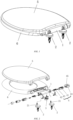
Fig. 1 is a perspective view of the present disclosure; -
Fig. 2 is an exploded view of the present disclosure; -
Fig. 3 is an partial exploded view of the present disclosure; -
Fig. 4 is a structural schematic diagram of the seat hinge; -
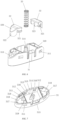
Fig. 5 is a structural schematic diagram of a button assembly; -
Fig. 6 is an exploded view of the button assembly; -
Fig. 7 is a structural schematic diagram of a button cover; -
Fig. 8 is a structural diagram of a button block; -
Fig. 9 is the first structural diagrams of the hinge body; -
Fig. 10 is the second schematic diagram of the hinge body; -
Fig. 11 is a structural schematic diagram of a transverse locking member; -
Fig. 12 is an assembly structure diagram of the hinged tube and the bottom plate; -
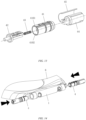
Fig. 13 is an exploded view of the buffer assembly; -
Fig. 14 is an assembly structure diagram of the buffer assembly and the hinged tube; -
FIG. 15 is a sectional view of the present disclosure; -
FIG. 16 is a partial sectional view of the present disclosure; -
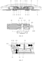
Fig. 17 is a structural sectional view showing the button assembly drives the transverse locking member to move; -
Fig. 18 is a structural schematic diagram of the latch connection between the transverse locking member and the hinge body; -
Fig. 19 is an assembly structure diagram of the transverse locking member and the seat hinge; -
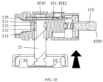
Fig. 20 is a structural diagram showing the seat hinge before it is inserted into the transverse locking member. - The present disclosure is further described in detail in combination with the attached drawings and specific embodiments.
- As shown in
Fig.1 to Fig.20 , a button integrated seat hinge, including ahinge tube 1 and afixed seat 2. The number of the fixedseat 2 is two, and the fixedseat 2 is provided with aseat hinge shaft 21. Thehinge tube 1 is provided with abutton assembly 3 andbuffer assemblies 4 provided at both ends of thebutton assembly 3. The number of thebuffer assemblies 4 is two, which corresponds to the seat hinges 2, and thebuffer assemblies 4 is symmetrical arranged. Thebutton assembly 3 is provided with a drivinginclined plane 320, and thebuffer assembly 4 includes ahinge body 41, atransverse locking member 42 and alocking reset spring 43 for driving the transverse lockingmember 42 to reset. Thetransverse locking member 42 is provided with abase body 420, alocking piece 421 and anelastic clamp piece 422 arranged on one side of thebase body 420 which are able to transversely insert into thehinge body 41, and a pushingrod 423 provided at the other side of thebase body 420. The end of the pushingrod 423 is provided with a conical pushingsurface 4230 matched with the drivinginclined plane 320, and the conical pushingsurface 4230 can be matched with the drivinginclined plane 320 at any angle, which can greatly reduce the requirements of machining accuracy and assembly accuracy, and improve the smoothness of mechanical matching. The end of theelastic clamp piece 422 is provided with alocking protrusion 4221, and thehinge body 41 is provided with alocking slot 412 matching with the lockingprotrusion 4221. Thetransverse locking member 42 and thehinge body 41 are positioned circumferentially by a circumferential positioning mechanism, which can effectively avoid the dislocation between the transverse lockingmember 42 and thehinge body 41, such that the mechanical structure stability is enhanced. The lower end of thehinge body 41 is provided with a seathinge shaft hole 411 for inserting theseat hinge shaft 21. Thetransverse locking member 42 is driven by thebutton assembly 3 to move outwards to make thelocking protrusion 4221 connect with thelocking slot 412 in a snap-fit when thebutton assembly 3 is pressed; and theelastic clamp piece 422 is driven by theseat hinge shaft 21 to perform elastic deformation when theseat hinge shaft 21 is pulled out from the seathinge shaft hole 411, so that the lockingprotrusion 4221 is moved out from thelocking slot 412, and the transverse lockingmember 42 is moved inward to reset under the action of the locking resetspring 43, such that it can be disassembled without pressing thebutton assembly 3 all the time, the operation is simple and convenient, and the design is ingenious. - As shown in
Fig.9 to Fig. 11 , thehinge body 41 is provided with a basebody containing cavity 410 matching with thebase body 420, wherein thebase body 420 is generally cylindrical. The circumferential positioning mechanism includes afirst positioning surface 4101 arranged in thehinge body 41 and asecond positioning surface 4201 arranged on thebase body 420. A first transverse guide slidingarc surface 4102 connected with thefirst positioning surface 4101 is arranged in thehinge body 41, a second guide slidingarc surface 4202 matching with the first transverse guide slidingarc surface 4102 is arranged on thebase body 420, and thefirst positioning surface 4101 and the first transverse guide slidingarc surface 4102 form the inner wall of the basebody containing cavity 410. Through the cooperation of thesecond positioning surface 4201 and thefirst positioning surface 4101, thehinge body 41 and the transverse lockingmember 42 can be fixed in the circumferential direction, and the force can be better carried out through thebase body 420, so as to prevent thelocking piece 421 andelastic clamp piece 422 from breaking under the force. - The
seat hinge shaft 21 is arranged with afirst boss 211 and asecond boss 212 successively from top to bottom, and a seat hingeshaft clamping groove 213 with a diameter smaller than thefirst boss 211 is formed between thefirst boss 211 and thesecond boss 212. A throughhole 4210 is provided on thelocking piece 421 for theseat hinge shaft 21 to pass through, and the outside of the throughhole 4210 is provided with a seat hingeshaft clamping opening 4211 communicated with the through hole and used for clamping with the seat hingeshaft clamping groove 213. And the upper end of thefirst boss 211 is provided with an insertion pushinginclined plane 216. When assembling, when theseat hinge shaft 21 is inserted into thehinge shaft hole 411 without pressing thebutton assembly 3, the transverse lockingmember 42 can be pushed to move outward by the insertion pushinginclined plane 216, but the moving distance of the transverse lockingmember 42 is not enough to make thelocking protrusion 4221 and thelocking slot 412 snap with each other. Therefore, when thefirst boss 211 passes through the throughhole 4210, the lockingreset spring 43 will drive the transverse lockingmember 42 to reset, which is a clever design. - As shown in
Fig.5 to Fig.8 , thebutton assembly 3 includes abutton cover 31, abutton block 32 assembled on the left and right sides of thebutton cover 31 and abutton reset spring 33 for driving thebutton cover 31 to reset, and the drivinginclined plane 320 is arranged on thebutton block 32. The button assembly uses the combined design, the corresponding parts can be replaced if it is damaged, which can effectively reduce the maintenance cost of the user. The two ends of thebutton cover 31 are respectively provided with abutton block cavity 310 for holding thebutton block 32, and thebutton block 32 is connected with thebutton cover 31 in snap-fit. Further, the front and rear side walls of thebutton cover 31 are respectively provided withsnap slots 311 communicated with thebutton block cavity 310, and thebutton block 32 is provided with a firstelastic snapping portion 321 connected with thesnap slots 311 in snap-fit, the assembly is simple and convenient, and damaged parts can be replaced easily, reducing maintenance costs. In order to meet the requirements for matching with the pushing transverse lockingmember 42 or the pushingrod 423 with different sizes, a plurality of thesnap slots 311 can be provided in longitudinal direction, and the assembly height of the firstelastic snapping portion 321 can be adjusted according to the requirements of different sizes by properly extending the firstelastic snapping portion 321, so as to meet the matching requirements with the pushing transverse lockingmember 42 or the pushingrod 423 with different sizes. - In order to enhance the strength of the structure, two longitudinal reinforcing
ribs 312 are arranged longitudinally in thebutton cover 31, so that aspring cavity 313 between the two longitudinal reinforcingribs 312 and thebutton block cavity 310 provided respectively on both sides of thespring cavity 313 are formed in thebutton cover 31. And thespring cavity 313 is provided with aspring fixing portion 314, and one end of the button resetspring 33 is sleeved on thespring fixing portion 314. Thespring fixing portion 314 is cruciform structure or cross shaped, so as to make the assembly of the button resetspring 33 firmly, which can effectively prevent the dislocation of the button reset spring and improve the assembly accuracy. - In the present embodiment, the front and rear side walls of the
button cover 31 are respectively provided with a second elastic snappingportion 315 and agap 316 on both sides of the second elastic snappingportion 315 and communicated with thespring cavity 313. The second elastic snappingportion 315 is connected with thehinge tube 1 in snap-fit, which can increase the assemble efficiency and the assembly qualification rate. - In the present embodiment, a raised
first limit block 317 is arranged in thebutton block cavity 310, thebutton block 32 is provided with a second clamping opening 322 matched with thefirst limit block 317, and a transverse reinforcingrib 323 is also arranged in thebutton block 32, and one side of the longitudinal reinforcingrib 312 facing theblock cavity 310 is provided with asecond limit block 318 and athird limit block 319 extending into thebutton block cavity 310. After assembly, one end of the transverse reinforcingrib 323 butts against thefirst limit block 317, and the other end of the transverse reinforcingrib 323 is located between thesecond limit block 318 and thethird limit block 319, which can effectively enhance the structure strength. - In the present embodiment, the upper end of the
second boss 212 is provided with ainclined plane 214. During assembly, if theseat hinge shaft 21 is inserted too deep or too hard for assembly, theinclined plane 214 can provide a certain buffer effect to prevent the transverse lockingmember 42 from being crushed. The lower end of thesecond boss 212 is provided with a first pull-out reset inclinedplane 215, theelastic clamp piece 422 is provided with areset protrusion 4222 located at the rear end of thelocking protrusion 4221 and matched with thesecond boss 212, and the upper end of thereset protrusion 4222 is provided with a second pull-out reset inclinedplane 4223 matched with the first pull-out reset inclinedplane 215. When thelocking protrusion 4221 and thelocking slot 412 are in the snap-fit connection state and theseat hinge shaft 21 is pulled out of thehinge shaft hole 411, the first pull-out reset inclinedplane 215 contacts with the second pull-out reset inclinedplane 4223, thesecond boss 212 pushes thereset protrusion 4222 to drive theelastic clamp piece 422 to perform elastic deformation, thereby thelocking protrusion 4221 is withdrawn from thelocking slot 412. Through the coordination of the inclined plane and the inclined plane, it is more conducive to the matching of thesecond boss 212 and the pushingreset protrusion 4222. In order to achieve better elastic deformation effect ofelastic clamp piece 422, the ratio between the distance between the lockingprotrusion 4221 and thereset protrusion 4222 and the distance between thereset protrusion 4222 and thebase body 420 is 0.20-0.35, and the optimum ratio is 0.25. - The
locking piece 421 is provided with alimit protrusion 4212 for connecting with thehinge body 41 in snap-fit, and thehinge body 41 is further provided with alimit slot 413 connected with thelimit protrusion 4212 in snap-fit. The length of thelimit slot 413 is greater than or equal to the moving stroke of the transverse lockingmember 42. Thelimit protrusion 4212 and thelimit slot 413 can limit the moving stroke of the transverse lockingmember 42. During assembly, thelimit protrusion 4212 can be snapped into thelimit slot 413, which can effectively prevent the transverse lockingmember 42 from falling off or pulling out. - In the present embodiment, the
hinge body 41 is provided with a lockingpiece insertion cavity 414 communicated with the basebody containing cavity 410 and used for the transverse insertion of thelocking piece 421, and thehinge body 41 is provided with an elastic clamppiece insertion cavity 415 communicated with the basebody containing cavity 410 and used for the transverse insertion of theelastic clamp piece 422, thelimit slot 413 is communicated with the lockingpiece insertion cavity 414, the seathinge shaft hole 411 is communicated with the lockingpiece insertion cavity 414, the seathinge shaft hole 411 is communicated with the elastic clamppiece insertion cavity 415. The matching degree can be enhanced to a certain extent by matching different cavities and components, so that thelocking piece 421 andelastic clamp piece 422 can be protected to prevent breakage. Thehinge body 41 is provided with aspring limit column 416. In order to make the transverse lockingmember 42 and thehinge body 41 more firmly assembled, and the transverse lockingmember 42 has uniform force and stable movement, the number of theelastic clamp pieces 422 is two and the two elastic clamp pieces are symmetrically arranged at the front side and the rear side of a lower end of thelocking piece 421, respectively. The locking resetspring 43 is located between the lockingpiece 421 and theelastic clamp piece 422, which can effectively save the space occupied by parts and reduce the product size, and reasonable use of the space between the lockingpiece 421 and theelastic clamp piece 422 will make the design more ingenious. One end of the locking resetspring 43 is against thebase body 420, and the other end of the locking resetspring 43 extends into the basebody containing cavity 410 and is sleeved on thespring limit column 416, the structure is simple. - In the present embodiment, the
buffer assembly 4 includes abuffer 44 and ananti-loose piece 45, and the outer side of thehinge body 41 is matched with the inner keyway of thebuffer 44, the structure is simple. Theanti-loose piece 45 is covered on the outer side ofhinge body 41 and thebuffer 44 to effectively prevent loose assembly between thehinge body 41 and thebuffer 44, so as to make assembly more firm. Thebuffer 44 is a common technical means in the art, which plays the role of shock absorption and damping, prevents thepanel 5 from falling suddenly and enables thepanel 5 to slowly drop down. In addition, thehinge tube 1 and thehinge body 41 are fixedly connected through theclamp fastener 7. Theclamp fastener 7 is a common technical means in the art, and will not be described in detail for brevity. - A combined cover plate with the button integrated seat hinge as described above, which includes a
panel 5 and abottom plate 6. As shown inFig. 10 , the rear end of thebottom plate 6 is threaded with thehinge tube 1, and thepanel 5 and thebottom plate 6 are movably connected through thebuffer assembly 4. A person skilled in the art can sell the button integrated seat hinge of the present disclosure by selling the cover plate assembly in a combined way, so as to facilitate the consumer to replace the cover plate assembly. - A toilet with the button integrated seat hinge as described above, which includes a
panel 5, abottom plate 6 and a toilet body. As shown inFig. 1 and Fig.2 , the rear end of thebottom plate 6 is threaded with thehinge tube 1, and thepanel 5 and thebottom plate 6 are movably connected through thebuffer assembly 4. The toilet body is provided with two fixedseat 2, wherein the fixedseat 2 is movably connected with thebuffer assembly 4. A person skilled in the art can sell the button integrated seat hinge and cover plate assembly of the present disclosure into a complete set of products in a combination way by selling the toilet. - The assembly process of the combined cover plate is as follows:
- 1. As shown in
Fig. 12 , thehinge tube 1 and thebottom plate 6 are connected by screws; - 2. Then, the
hinge body 41, the transverse lockingmember 42, the lockingreset spring 43, thebuffer 44 and theanti-loose piece 45 are assembled together to form abuffer assembly 4, and thebuffer assembly 4 is assembled in thehinge tube 1 as shown inFig. 14 ; - 3. The
seat hinge 2 is assembled on the toilet body; - 4. The
seat hinge shaft 21 is inserted into thebuffer assembly 4 to complete the installation. - The replacement process of the combined cover plate provided by the present disclosure is as follows:
- 1. As shown in
Fig. 17 , pressing thebutton assembly 3, so that thebutton assembly 3 pushes the twotransverse locking members 42 to move to both sides. As shown inFig. 18 , the lockingprotrusion 4221 is snapped into thelocking slot 412 to complete the snap connection between thehinge body 41 and the transverse lockingmember 42; - 2. Lifting up the combined cover plate and pulling it out to complete the disassembly;
- 3. As shown in
Fig. 20 , the installation can be completed by inserting the new combined cover plate into thehinge shaft 21 and thebuffer assembly 4. The operation is simple and convenient.
Claims (10)
- A button integrated seat hinge for toilets,comprising a hinge tube (1) and a fixed seat (2), the fixed seat (2) is provided with a seat hinge shaft (21), the hinge tube (1) is provided with a button assembly (3), and buffer assemblies (4) are provided at both ends of the button assembly (3), the button assembly (3) is provided with a driving inclined plane (320); the buffer assembly (4) comprises a hinge body (41), a transverse locking member (42) and a locking reset spring driving the transverse locking member (42) to reset, the transverse locking member (42) is provided with a base body (420), a locking piece (421) and an elastic clamp piece (422) arranged on one side of the base body (420) which are able to transversely insert into the hinge body (41), and a pushing rod (423) provided at the other side of the base body (420); an end of the pushing rod (423) is provided with a conical pushing surface (4230) matched with the driving inclined plane (320); an end of the elastic clamp piece (422) is provided with a locking protrusion (4221), and the hinge body (41) is provided with a locking slot (412) matching with the locking protrusion (4221); the transverse locking member (42) and the hinge body (41) are positioned circumferentially by a circumferential positioning mechanism; a lower end of the hinge body (41) is provided with a seat hinge shaft hole (411) for inserting the seat hinge shaft (21); the transverse locking member (42) is driven by the button assembly (3) to move outwards to make the locking protrusion (4221) connect with the locking slot (412) in a snap-fit when the button assembly (3) is pressed, the elastic clamp piece (422) is driven by the seat hinge shaft (21) to elastically deform when the seat hinge shaft (21) is pulled out from the seat hinge shaft hole (411), so that the locking protrusion (4221) is moved out from the locking slot (412), and the transverse locking member (42) is moved inward to reset under an action of the locking reset spring (43);the hinge body (41) is provided with a base body containing cavity (410) matching with the base body (420); the circumferential positioning mechanism comprises a first positioning surface (4101) arranged in the hinge body (41) and a second positioning surface (4201) arranged on the base body (420); a first transverse guide sliding arc surface (4102) connected with the first positioning surface (4101) is arranged in the hinge body (41), a second guide sliding arc surface (4202) matching with the first transverse guide sliding arc surface (4102) is arranged on the base body (420), and the first positioning surface (4101) and the first transverse guide sliding arc surface (4102) form an inner wall of the base body containing cavity (410);the seat hinge shaft (21) is arranged with a first boss (211) and a second boss (212) successively from top to bottom, and a seat hinge shaft clamping groove (213) with a diameter smaller than the first boss (211) is formed between the first boss (211) and the second boss (212), and a through hole (4210) is provided on the locking piece (421) for the seat hinge shaft (21) to pass through; an outside of the through hole (4210) is provided with a seat hinge shaft clamping opening (4211) communicated with the through hole (4210) and used for clamping with the seat hinge shaft clamping groove (213); an upper end of the first boss (211) is provided with an insertion pushing inclined plane (216);the lower end of the second boss (212) is provided with a first pull-out reset inclined plane (215); the elastic clamp piece (422) is provided with a reset protrusion (4222) located at a rear end of the locking protrusion (4221) and matched with the second boss (212), and an upper end of the reset protrusion (4222) is provided with a second pull-out reset inclined plane (4223)matched with the first pull-out reset inclined plane (215); when the locking protrusion (4221) and the locking slot (412) are in the snap-fit connection state and the seat hinge shaft (21) is pulled out of the hinge shaft hole (411), the second boss (212) drives the elastic clamp piece (422) to elastic deformation by pushing the reset protrusion (4222), thereby the locking protrusion (4221) is withdrawn from the locking slot (412); and characterized in thatthe button assembly (3) comprises a button cover (31), a button block (32) assembled on left and right sides of the button cover (31) and a button reset spring (33) for driving the button cover (31) to reset; the driving inclined plane (320) is arranged on the button block (32), and two ends of the button cover (31) are respectively provided with a button block cavity (310) for holding the button block (32); and the button block (32) is connected with the button cover (31) in snap-fit;the locking piece (421) is provided with a limit protrusion (4212) for connecting with the hinge body (41), and the hinge body (41) is provided with a limit slot (413) connected with the limit protrusion (4212); a length of the limit slot (413) is greater than or equal to a moving stroke of the transverse locking member (42).
- The button integrated seat hinge according to claim 1, characterized in that front and rear side walls of the button cover (31) are respectively provided with snap slots (311) communicated with the button block cavity (310), and the button block (32) is provided with a first elastic snapping portion (321) connected with the snap slots (311).
- The button integrated seat hinge according to claim 2, characterized in that two longitudinal reinforcing ribs (312) are arranged longitudinally in the button cover (31), so that a spring cavity (313) between the two longitudinal reinforcing ribs (312) and the button block cavity (310) provided respectively on both sides of the spring cavity (313) are formed in the button cover (31) ; and the spring cavity (313) is provided with a spring fixing portion (314), and one end of the button reset spring (33) is sleeved on the spring fixing portion (314).
- The button integrated seat hinge according to claim 3, characterized in that the front and rear side walls of the button cover (31) are respectively provided with a second elastic snapping portion (315) and a gap (316) on both sides of the second elastic snapping portion (315) and communicated with the spring cavity (313); the second elastic snapping portion (315) is connected with the hinge tube (1) in snap-fit.
- The button integrated seat hinge according to claim 3, characterized in that a raised first limit block (317) is arranged in the button block cavity (310), the button block (32) is provided with a second clamping opening (322) matched with the first limit block (317), and a transverse reinforcing rib (323) is arranged in the button block (32), and one side of the longitudinal reinforcing rib (312) facing the button block cavity (310) is provided with a second limit block (318) and a third limit block (319) extending into the button block cavity (310); after assembly, one end of the transverse reinforcing rib (323) butts against the first limit block (317), and the other end of the transverse reinforcing rib (323) is located between the second limit block (318) and the third limit block (319).
- The button integrated seat hinge according to claim 1, characterized in that a ratio between a distance between the locking protrusion (4221) and the reset protrusion (4222) and a distance between the reset protrusion (4222) and the base body (420) is 0.20-0.35.
- The button integrated seat hinge according to claim 1, characterized in that the hinge body (41) is provided with a locking piece insertion cavity (414) communicated with the base body containing cavity (410) and used for the transverse insertion of the locking piece (421); the hinge body (41) is provided with an elastic clamp piece insertion cavity (415) communicated with the base body containing cavity (410) and used for the transverse insertion of the elastic clamp piece (422), the limit slot (413) is communicated with the locking piece insertion cavity (414), the seat hinge shaft hole (411) is communicated with the locking piece insertion cavity (414), the seat hinge shaft hole (411) is communicated with the elastic clamp piece insertion cavity (415); the hinge body (41) is provided with a spring limit column (416); the number of the elastic clamp pieces (422) is two and the two elastic clamp pieces are symmetrically arranged at a front side and a rear side of a lower end of the locking piece (421), respectively; the locking reset spring (43) is located between the locking piece (421) and the elastic clamp piece (422), one end of the locking reset spring (43) is against the base body (420), and the other end of the locking reset spring (43) extends into the base body containing cavity (410) and is sleeved on the spring limit column (416).
- The button integrated seat hinge according to claim 1, characterized in that the buffer assembly (4) comprises a buffer (44), and an outer side of the hinge body (41) is matched with an inner keyway of the buffer (44); the hinge tube (1) and the hinge body (41) are fixedly connected through the clamp fastener (7).
- A combined cover plate with the button integrated seat hinge according to any one of claims 1-8, characterized in that, comprising a panel (5) and a bottom plate (6), a rear end of the bottom plate (6) is threaded with the hinge tube (1), and the panel (5) and the bottom plate (6) are movably connected through the buffer assembly (4).
- A toilet with the button integrated seat hinge according to any one of claims 1-8, characterized in that, comprising a panel (5), a bottom plate (6) and a toilet body; a rear end of the bottom plate (6) is threaded with the hinge tube (1), and the panel (5) and the bottom plate (6) are movably connected through the buffer assembly (4); the toilet body is provided with two of the fixed seat (2), wherein the fixed seat (2) is movably connected with the buffer assembly (4).
Applications Claiming Priority (1)
| Application Number | Priority Date | Filing Date | Title |
|---|---|---|---|
| CN202011290136.2A CN112401726B (en) | 2020-11-18 | 2020-11-18 | Button integrated seat hinge and application thereof |
Publications (3)
| Publication Number | Publication Date |
|---|---|
| EP4000486A1 EP4000486A1 (en) | 2022-05-25 |
| EP4000486B1 true EP4000486B1 (en) | 2024-12-25 |
| EP4000486C0 EP4000486C0 (en) | 2024-12-25 |
Family
ID=74105764
Family Applications (1)
| Application Number | Title | Priority Date | Filing Date |
|---|---|---|---|
| EP20217364.7A Active EP4000486B1 (en) | 2020-11-18 | 2020-12-28 | Button integrated seat hinge and its application |
Country Status (3)
| Country | Link |
|---|---|
| EP (1) | EP4000486B1 (en) |
| CN (1) | CN112401726B (en) |
| ES (1) | ES3005708T3 (en) |
Families Citing this family (5)
| Publication number | Priority date | Publication date | Assignee | Title |
|---|---|---|---|---|
| JP7531219B2 (en) | 2021-03-09 | 2024-08-09 | 株式会社Tok | Detachable device |
| CN116676761B (en) * | 2023-06-06 | 2023-10-27 | 盐城立德塑业有限公司 | Washing machine cover plate convenient to replace |
| CN116763173B (en) * | 2023-07-04 | 2025-11-18 | 箭牌家居集团股份有限公司 | Toilet seat opening assist and toilet seat assembly |
| CN117301452A (en) * | 2023-07-28 | 2023-12-29 | 惠州市富佳胜电子技术有限公司 | A mold for producing light guide plates |
| CN121041104A (en) * | 2024-05-31 | 2025-12-02 | 浙江英洛华康复器材有限公司 | Folding locking mechanism and wheelchair including the mechanism |
Citations (1)
| Publication number | Priority date | Publication date | Assignee | Title |
|---|---|---|---|---|
| CN210300827U (en) * | 2019-05-31 | 2020-04-14 | 中山市美图塑料工业有限公司 | Detachable toilet cover plate with top button structure |
Family Cites Families (9)
| Publication number | Priority date | Publication date | Assignee | Title |
|---|---|---|---|---|
| TW200635101A (en) * | 2005-03-18 | 2006-10-01 | Fih Co Ltd | Battery cover structure |
| CN201211152Y (en) * | 2008-07-09 | 2009-03-25 | 周裕佳 | Quick assembling and disassembling mechanism for toilet seat and cover plate |
| CN104219984B (en) * | 2011-12-23 | 2017-03-15 | 厦门倍恩卫浴有限公司 | The fast assembly and disassembly mechanism of one-touch lavatory lid group |
| DE202014101077U1 (en) * | 2014-02-14 | 2014-06-04 | Bestter (Xiamen) Technology Inc. | Swivel of a lid and a body of a toilet |
| DE102015112227A1 (en) * | 2015-07-27 | 2017-02-02 | Hamberger Industriewerke Gmbh | Joint arrangement and rotary damper |
| CN107137003A (en) * | 2017-07-17 | 2017-09-08 | 厦门德浦精密科技有限公司 | A kind of individual palpation fast-assembling cover plate assembly |
| CN208274529U (en) * | 2017-08-22 | 2018-12-25 | 中山市美图塑料工业有限公司 | A quick-detachable cover assembly |
| CN109602317A (en) * | 2019-01-07 | 2019-04-12 | 广东英乐斯陶瓷科技有限公司 | A kind of installation structure of toilet seat cover board |
| CN210961752U (en) * | 2019-05-23 | 2020-07-10 | 箭牌家居集团股份有限公司 | Closestool cover plate hinge assembly |
-
2020
- 2020-11-18 CN CN202011290136.2A patent/CN112401726B/en active Active
- 2020-12-28 EP EP20217364.7A patent/EP4000486B1/en active Active
- 2020-12-28 ES ES20217364T patent/ES3005708T3/en active Active
Patent Citations (1)
| Publication number | Priority date | Publication date | Assignee | Title |
|---|---|---|---|---|
| CN210300827U (en) * | 2019-05-31 | 2020-04-14 | 中山市美图塑料工业有限公司 | Detachable toilet cover plate with top button structure |
Also Published As
| Publication number | Publication date |
|---|---|
| EP4000486A1 (en) | 2022-05-25 |
| CN112401726A (en) | 2021-02-26 |
| EP4000486C0 (en) | 2024-12-25 |
| CN112401726B (en) | 2022-09-13 |
| ES3005708T3 (en) | 2025-03-17 |
Similar Documents
| Publication | Publication Date | Title |
|---|---|---|
| EP4000486A1 (en) | Push-button integrated seat hinge and its application | |
| CN217440321U (en) | Storable fan | |
| WO2001046542A9 (en) | Linkage member for an anti-tip/interlock device | |
| CN103099580B (en) | Quick release auxiliary mechanism of cover plate of closestool | |
| EP3769653B1 (en) | Toilet cover plate hinge seat easy to disassemble and assemble | |
| CN112178013B (en) | A knob type locking device and front maintenance LED splicing screen | |
| GB2490297A (en) | Conveniently removable toilet cover board connection device | |
| CN210343971U (en) | Connector, LED box and LED display screen based on ball | |
| CN210874274U (en) | Filter element mounting structure, water purifier and water purifying dispenser | |
| CN113749435B (en) | A simple disassembly and assembly structure of a drawer | |
| CN218481763U (en) | Watchcase and wrist-watch with detachable circle mouth | |
| US20230415843A1 (en) | Crank quick-connection structure, pedal assembly, and bicycle | |
| CN216020754U (en) | Quick dismounting device for side edge of toilet cover plate | |
| CN104633607A (en) | Flashlight and fixing structure thereof | |
| CN209996186U (en) | toilet cover plate assembling structure | |
| CN101113864B (en) | Support of refrigerator door and door lock device | |
| CN221411090U (en) | Bottle installation device and commodity shelf | |
| CN220735268U (en) | Quick assembly disassembly's closestool seat circle | |
| CN114348305B (en) | Spatial on-orbit turntable limiting mechanism and assembling method thereof | |
| CN223247816U (en) | Detachable type furniture storage cabinet | |
| CN220769134U (en) | Cylinder lock with conveniently replaced lock tongue | |
| CN220452382U (en) | Lightweight hydro-cylinder structure | |
| CN224251287U (en) | Cover plate mounting structure and closestool | |
| CN108784136B (en) | Infant supporting device | |
| CN224107510U (en) | Detachable automobile door plate buckle |
Legal Events
| Date | Code | Title | Description |
|---|---|---|---|
| PUAI | Public reference made under article 153(3) epc to a published international application that has entered the european phase |
Free format text: ORIGINAL CODE: 0009012 |
|
| STAA | Information on the status of an ep patent application or granted ep patent |
Free format text: STATUS: THE APPLICATION HAS BEEN PUBLISHED |
|
| AK | Designated contracting states |
Kind code of ref document: A1 Designated state(s): AL AT BE BG CH CY CZ DE DK EE ES FI FR GB GR HR HU IE IS IT LI LT LU LV MC MK MT NL NO PL PT RO RS SE SI SK SM TR |
|
| STAA | Information on the status of an ep patent application or granted ep patent |
Free format text: STATUS: REQUEST FOR EXAMINATION WAS MADE |
|
| 17P | Request for examination filed |
Effective date: 20221014 |
|
| RBV | Designated contracting states (corrected) |
Designated state(s): AL AT BE BG CH CY CZ DE DK EE ES FI FR GB GR HR HU IE IS IT LI LT LU LV MC MK MT NL NO PL PT RO RS SE SI SK SM TR |
|
| STAA | Information on the status of an ep patent application or granted ep patent |
Free format text: STATUS: EXAMINATION IS IN PROGRESS |
|
| 17Q | First examination report despatched |
Effective date: 20240423 |
|
| GRAP | Despatch of communication of intention to grant a patent |
Free format text: ORIGINAL CODE: EPIDOSNIGR1 |
|
| STAA | Information on the status of an ep patent application or granted ep patent |
Free format text: STATUS: GRANT OF PATENT IS INTENDED |
|
| RIC1 | Information provided on ipc code assigned before grant |
Ipc: A47K 13/26 20060101ALN20240913BHEP Ipc: A47K 13/12 20060101ALN20240913BHEP Ipc: A47K 13/00 20060101AFI20240913BHEP |
|
| INTG | Intention to grant announced |
Effective date: 20240927 |
|
| GRAS | Grant fee paid |
Free format text: ORIGINAL CODE: EPIDOSNIGR3 |
|
| GRAA | (expected) grant |
Free format text: ORIGINAL CODE: 0009210 |
|
| STAA | Information on the status of an ep patent application or granted ep patent |
Free format text: STATUS: THE PATENT HAS BEEN GRANTED |
|
| RIN1 | Information on inventor provided before grant (corrected) |
Inventor name: ZHANG, HAI Inventor name: HUANG, HAOJIA Inventor name: ZHOU, WENHUI |
|
| AK | Designated contracting states |
Kind code of ref document: B1 Designated state(s): AL AT BE BG CH CY CZ DE DK EE ES FI FR GB GR HR HU IE IS IT LI LT LU LV MC MK MT NL NO PL PT RO RS SE SI SK SM TR |
|
| REG | Reference to a national code |
Ref country code: GB Ref legal event code: FG4D |
|
| REG | Reference to a national code |
Ref country code: CH Ref legal event code: EP |
|
| REG | Reference to a national code |
Ref country code: DE Ref legal event code: R096 Ref document number: 602020043620 Country of ref document: DE |
|
| REG | Reference to a national code |
Ref country code: IE Ref legal event code: FG4D |
|
| U01 | Request for unitary effect filed |
Effective date: 20250110 |
|
| U07 | Unitary effect registered |
Designated state(s): AT BE BG DE DK EE FI FR IT LT LU LV MT NL PT RO SE SI Effective date: 20250117 |
|
| U20 | Renewal fee for the european patent with unitary effect paid |
Year of fee payment: 5 Effective date: 20250120 |
|
| REG | Reference to a national code |
Ref country code: ES Ref legal event code: FG2A Ref document number: 3005708 Country of ref document: ES Kind code of ref document: T3 Effective date: 20250317 |
|
| PG25 | Lapsed in a contracting state [announced via postgrant information from national office to epo] |
Ref country code: HR Free format text: LAPSE BECAUSE OF FAILURE TO SUBMIT A TRANSLATION OF THE DESCRIPTION OR TO PAY THE FEE WITHIN THE PRESCRIBED TIME-LIMIT Effective date: 20241225 |
|
| PG25 | Lapsed in a contracting state [announced via postgrant information from national office to epo] |
Ref country code: NO Free format text: LAPSE BECAUSE OF FAILURE TO SUBMIT A TRANSLATION OF THE DESCRIPTION OR TO PAY THE FEE WITHIN THE PRESCRIBED TIME-LIMIT Effective date: 20250325 |
|
| PG25 | Lapsed in a contracting state [announced via postgrant information from national office to epo] |
Ref country code: GR Free format text: LAPSE BECAUSE OF FAILURE TO SUBMIT A TRANSLATION OF THE DESCRIPTION OR TO PAY THE FEE WITHIN THE PRESCRIBED TIME-LIMIT Effective date: 20250326 |
|
| PG25 | Lapsed in a contracting state [announced via postgrant information from national office to epo] |
Ref country code: RS Free format text: LAPSE BECAUSE OF FAILURE TO SUBMIT A TRANSLATION OF THE DESCRIPTION OR TO PAY THE FEE WITHIN THE PRESCRIBED TIME-LIMIT Effective date: 20250325 |
|
| PG25 | Lapsed in a contracting state [announced via postgrant information from national office to epo] |
Ref country code: SM Free format text: LAPSE BECAUSE OF FAILURE TO SUBMIT A TRANSLATION OF THE DESCRIPTION OR TO PAY THE FEE WITHIN THE PRESCRIBED TIME-LIMIT Effective date: 20241225 |
|
| PG25 | Lapsed in a contracting state [announced via postgrant information from national office to epo] |
Ref country code: PL Free format text: LAPSE BECAUSE OF FAILURE TO SUBMIT A TRANSLATION OF THE DESCRIPTION OR TO PAY THE FEE WITHIN THE PRESCRIBED TIME-LIMIT Effective date: 20241225 |
|
| PG25 | Lapsed in a contracting state [announced via postgrant information from national office to epo] |
Ref country code: IS Free format text: LAPSE BECAUSE OF FAILURE TO SUBMIT A TRANSLATION OF THE DESCRIPTION OR TO PAY THE FEE WITHIN THE PRESCRIBED TIME-LIMIT Effective date: 20250425 |
|
| PG25 | Lapsed in a contracting state [announced via postgrant information from national office to epo] |
Ref country code: SK Free format text: LAPSE BECAUSE OF FAILURE TO SUBMIT A TRANSLATION OF THE DESCRIPTION OR TO PAY THE FEE WITHIN THE PRESCRIBED TIME-LIMIT Effective date: 20241225 |
|
| PG25 | Lapsed in a contracting state [announced via postgrant information from national office to epo] |
Ref country code: CZ Free format text: LAPSE BECAUSE OF FAILURE TO SUBMIT A TRANSLATION OF THE DESCRIPTION OR TO PAY THE FEE WITHIN THE PRESCRIBED TIME-LIMIT Effective date: 20241225 |
|
| REG | Reference to a national code |
Ref country code: CH Ref legal event code: PL |
|
| PG25 | Lapsed in a contracting state [announced via postgrant information from national office to epo] |
Ref country code: MC Free format text: LAPSE BECAUSE OF FAILURE TO SUBMIT A TRANSLATION OF THE DESCRIPTION OR TO PAY THE FEE WITHIN THE PRESCRIBED TIME-LIMIT Effective date: 20241225 |
|
| PG25 | Lapsed in a contracting state [announced via postgrant information from national office to epo] |
Ref country code: CH Free format text: LAPSE BECAUSE OF NON-PAYMENT OF DUE FEES Effective date: 20241231 |
|
| PG25 | Lapsed in a contracting state [announced via postgrant information from national office to epo] |
Ref country code: IE Free format text: LAPSE BECAUSE OF NON-PAYMENT OF DUE FEES Effective date: 20241228 |
|
| PLBE | No opposition filed within time limit |
Free format text: ORIGINAL CODE: 0009261 |
|
| STAA | Information on the status of an ep patent application or granted ep patent |
Free format text: STATUS: NO OPPOSITION FILED WITHIN TIME LIMIT |
|
| 26N | No opposition filed |
Effective date: 20250926 |
|
| U20 | Renewal fee for the european patent with unitary effect paid |
Year of fee payment: 6 Effective date: 20251111 |
|
| PGFP | Annual fee paid to national office [announced via postgrant information from national office to epo] |
Ref country code: GB Payment date: 20251112 Year of fee payment: 6 |
|
| PGFP | Annual fee paid to national office [announced via postgrant information from national office to epo] |
Ref country code: ES Payment date: 20260105 Year of fee payment: 6 |
|
| PG25 | Lapsed in a contracting state [announced via postgrant information from national office to epo] |
Ref country code: CY Free format text: LAPSE BECAUSE OF FAILURE TO SUBMIT A TRANSLATION OF THE DESCRIPTION OR TO PAY THE FEE WITHIN THE PRESCRIBED TIME-LIMIT Effective date: 20241225 |
|
| PG25 | Lapsed in a contracting state [announced via postgrant information from national office to epo] |
Ref country code: HU Free format text: LAPSE BECAUSE OF FAILURE TO SUBMIT A TRANSLATION OF THE DESCRIPTION OR TO PAY THE FEE WITHIN THE PRESCRIBED TIME-LIMIT; INVALID AB INITIO Effective date: 20201228 |