EP4000378A1 - Landwirtschaftliche arbeitsmaschine mit einer trommel - Google Patents
Landwirtschaftliche arbeitsmaschine mit einer trommel Download PDFInfo
- Publication number
- EP4000378A1 EP4000378A1 EP21195437.5A EP21195437A EP4000378A1 EP 4000378 A1 EP4000378 A1 EP 4000378A1 EP 21195437 A EP21195437 A EP 21195437A EP 4000378 A1 EP4000378 A1 EP 4000378A1
- Authority
- EP
- European Patent Office
- Prior art keywords
- drum
- crop
- working machine
- agricultural working
- machine according
- Prior art date
- Legal status (The legal status is an assumption and is not a legal conclusion. Google has not performed a legal analysis and makes no representation as to the accuracy of the status listed.)
- Granted
Links
Images


Classifications
-
- A—HUMAN NECESSITIES
- A01—AGRICULTURE; FORESTRY; ANIMAL HUSBANDRY; HUNTING; TRAPPING; FISHING
- A01F—PROCESSING OF HARVESTED PRODUCE; HAY OR STRAW PRESSES; DEVICES FOR STORING AGRICULTURAL OR HORTICULTURAL PRODUCE
- A01F12/00—Parts or details of threshing apparatus
- A01F12/10—Feeders
Definitions
- the invention relates to an agricultural working machine with a cylindrical drum according to the preamble of claim 1.
- Agricultural working machines include combine harvesters, forage harvesters or balers.
- the DE 10 2004 048 084 A1 discloses a drum designed as a feed drum of a combine harvester.
- Such devices include a drive shaft, a drum shell arranged concentrically around the drive shaft and drum plates located on the end faces for fastening the drum shell to the drive shaft.
- the drum plates extend perpendicularly to the drive shaft and have a bevel on their outer diameter, the bevel being welded to the drum shell.
- crop guiding elements arranged on the outside of the drum jacket convey the harvested crop to a separating device downstream of the feed drum in terms of process technology.
- the formation of dust and material residues which can essentially consist of waste (chaff), awns and other impurities, is particularly pronounced here, particularly on the feed drum.
- the impurities pass through a gap located between the front end of the drum casing and the body side wall of the combine harvester. Due to the small gap dimensions between the drum and the side wall, the contamination can only escape to a limited extent. However, the small gap dimensions are necessary to prevent long straw from being wrapped around the drive shaft. Furthermore, for assembly reasons, the drum plates are arranged at a distance from the respective lateral end of the drum shell, so that a surface extending in the axial direction of the drum is formed between the drum plate and the lateral end of the drum shell. The disadvantage is that the impurities collect on the inside of the drum shell on this surface and are deposited there due to the centrifugal forces. During harvesting, an ever-increasing layer of deposits builds up, which can eventually rub against the side wall of the body when the drum rotates and can lead to an imbalance in the drum.
- an agricultural working machine in particular a combine harvester, is proposed with a cylindrical drum, the drum comprising at least one drive shaft, a drum casing concentrically surrounding the drive shaft and opposite end faces.
- a crop deflection element that is at least partially funnel-shaped in the opening direction is assigned to the end faces.
- impurities that get through a gap between the end of the drum and a body side wall arranged parallel to the respective end face are carried back along the funnel-shaped goods deflection element in the direction of the gap and from there to the outside again due to the centrifugal force.
- the material deflection element prevents contaminants from settling on a surface extending in the axial direction on the inside of the drum casing.
- funnel-shaped means that the crop deflector element widens from the inside out of the drum in the direction of the front opening.
- the funnel-shaped goods deflection elements form an end face of the drum that expands from the inside out of the drum in a substantially truncated cone shape.
- the goods deflection elements which are funnel-shaped at least in sections, can comprise a plurality of goods routing channels, the goods routing channels segmenting the funnel-shaped goods deflection elements, in particular in the shape of a sector of a circle.
- a circular section-shaped segment of the goods deflection element can be arranged in each case between two goods guiding channels.
- the funnel-shaped material guide channels support the removal of impurities on the front sides.
- the material guide channels advantageously extend in the radial direction of the drum.
- recesses can be provided in the drum casing radially on the outside of the material guide channels, so that any impurities are carried out of the drum through the recesses.
- crop processing means in particular crop guide elements
- the recesses being located between two crop processing means, so that the impurities be conveyed unhindered along the Gutleitkanale and through the recesses out of the drum.
- the crop guide channels preferably end radially on the outside between two crop processing means arranged at a distance from one another.
- Inserts arranged separately on the drum can preferably form the funnel-shaped crop deflection elements in order to enable easy retrofitting and easy manufacturability of the drum and the crop deflection element.
- the inserts can be arranged on the drum in a detachable manner, preferably by means of a screw connection.
- the inserts can be attached to the drum in a particularly simple manner.
- the inserts can each be designed as a blank, with the respective blank comprising two opposite bases and a lateral surface located radially on the outside between the bases, with the first base of the respective blank forming a funnel-shaped end face.
- the drum can preferably comprise drum plates located on the front side, with the drum plates extending essentially perpendicularly to the drive shaft, with the drum plates being arranged stationarily on the drive shaft and stationarily on the inside of the drum shell.
- the second base side of the circular blank which is opposite the first base side, can be arranged on the drum plate, in particular detachably.
- This is particularly advantageous, since in this way production-related openings within the drum plate can be closed in a simple manner by means of the circular blank, and contamination is prevented from penetrating into the drum.
- the drum plate can have a chamfer resting on the inner side of the lateral surface, with the chamfer having a cutout radially on the outside of a material guide channel.
- the crop deflection elements can end with the end of the drum shell in the opening direction.
- the drum can preferably be designed as a feed drum of a combine harvester. Since a particularly large amount of dust forms in the area of the feed drum of a combine harvester, an assignment of crop deflection elements on the end faces of the feed drum is particularly advantageous.
- figure 1 shows a detail of a known agricultural machine designed as a combine harvester 1 with a threshing unit 2 and a separating device 3 in a schematic side view.
- the separating device 3 here comprises two axial rotors 4 arranged parallel next to one another, only the axial rotor 4 located on the left-hand side of the vehicle in the direction of travel FR being recognizable in the schematic representation shown.
- the combine harvester 1 has a front side 5 on which a driver's cab 6 for an operator (not shown) is arranged.
- a cutting unit (not shown) is also arranged on the front side 5 and picks up harvested crop (not shown).
- the cutting unit directs the harvested crop into a feederhouse 7 arranged below the driver's cab, via which the harvested crop is directed as a harvested crop stream 8 into the threshing mechanism 2 of the combine harvester 1 .
- the threshing unit 2 has three crop processing elements 9, 10, 11, namely an acceleration drum 9, which is arranged upstream of a threshing drum 10, the threshing drum 10 and a feed drum 11 arranged downstream of the threshing drum 10.
- the acceleration drum 9 is used to accelerate and pre-thresh the Crop and for feeding the crop to the threshing cylinder 10 is provided.
- the threshing drum 10 threshes the crop.
- the crop processing organs 9-11 of the threshing mechanism 2 are arranged transversely to the direction of travel FR.
- a concave 12 is arranged below the acceleration drum 9 and the threshing drum 10. Loosened grain (not shown) is separated from the crop flow 8 by the concave 12 .
- the feed drum 11 transfers the harvested crop to one of these downstream inlet head housings 13 of the separating device 3 , with the inlet head housing 13 forming an inlet area 14 for the crop conveyed from the feed drum 11 to the axial rotors 4 .
- the axial rotors 4 are mounted on the inlet head housing 13 at a front inlet end.
- the feed drum 11 is designed as a separating drum, which divides the crop flow 8 into two partial flows, which are each fed to one of the two axial rotors 4 .
- an inlet segment 16 can also be arranged below the feed drum 11 .
- the inlet segment 16 has a larger diameter than the feed drum 11 and at least partially surrounds the feed drum 11 . It forms an extension of the inlet area 14 into the separating device 4.
- the combine harvester includes a cleaning device that is known per se and is not explained in more detail here.
- FIG 2a shows a section of the feed drum 11 with a crop deflector element 15 and assigned to the feed drum 11
- Figure 2b shows the end face 17 of the feed drum 11 accordingly Figure 2a in a sectional view.
- the feed drum 11 consists essentially of a cylindrical drum 18 with crop guiding elements 19 arranged on the outside of the drum 18 .
- the drum 18 To fasten the drum shell 21 to the drive shaft 20, the drum 18 includes drum plates 22 on the front side.
- the drum plates 22 extend in the radial direction starting from the drive shaft 20 and are fixed in place on the drive shaft 20, for example welded.
- the drum plates 22 On the outside, the drum plates 22 each have a bevel 23 that extends in the opening direction OR of the drum 18 extends along the inside of the drum shell 21 and is stationarily connected to the drum shell 21 .
- the end faces 17 of the drum 18 are each assigned a crop deflection element 15 that is funnel-shaped at least in sections in the opening direction OR.
- the funnel-shaped goods deflection elements 15 form an end face 24 of the drum 18 that widens from the inside out of the drum 18 in the opening direction OR.
- the drum plate 22 itself can form the item deflection element 15 or be configured in one piece with the item deflection element 15 .
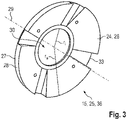
- the insert 36 is as in figure 3 shown, formed as a circular blank 25 with two opposite base sides 26, 27 and an outer lateral surface 28 located between the opposite base sides 26, 27.
- the blank 25 has a bore 30 along its axis of rotation 29 and is arranged concentrically around the drive shaft 20 .
- the distance between the opposing bases 26, 27 of the blank 25 is small compared to the radius r a of the lateral surface 28.
- the first base 26 of the circular blank 25 forms the end face 24 of the drum 18, the first base 26 expanding in the axial direction, starting from its inner radius r i towards its outer radius r a .
- the second base side 27 of the circular blank 25 opposite the first base side 26 is flat and rests against the drum plate 22 .
- the lateral surface 28 of the blank 25 rests radially on the outside against the bevel 23 of the drum plate 22 and on the inside 31 of the drum casing 21 .
- the lateral surface 28 terminates with the end 32 of the drum casing 21, so that an accumulation of impurities on the inside of the drum casing 21 is avoided.
- the blank 25 forms an essentially frustoconical opening on the respective end face 17 of the drum 18.
- a plurality of material guide channels 33 are arranged on the circular blank 25, which extend in the radial direction of the drum 18 and segment the funnel-shaped first base side 26 in the shape of a sector of a circle.
- the crop guide channels 33 have a rectangular profile, which has proven to be particularly advantageous for avoiding crop deposits.
- the material guide channels 33 can also have an arcuate profile, for example.
- Radially outside the Gutleitkanalen 33 are recesses 34 both within the fold 23 of the drum plate 22 and within the drum shell 21, so that impurities in the operating state along the Gutleitkanalen 33 are passed through the centrifugal forces to the outside.
- the recesses 34 are each located between two crop guiding elements 19 which are arranged spaced apart from one another on the outside of the drum shell 21 .
- the drum plates 22 of the drum shown in the exemplary embodiment include openings 35 through which paint or lacquer gets into the drum 18 during a dip.
- the circular blank 25 closes these openings 35, in particular by means of its second base side 27, so that no harvested crop enters the drum 18 and no additional means for closing the openings 35 are required.
- the circular blank 25 it is possible to manufacture the circular blank 25 as a milled part, for example made of plastic, or as a deep-drawn part, for example made of steel.
Landscapes
- Life Sciences & Earth Sciences (AREA)
- Environmental Sciences (AREA)
- Harvester Elements (AREA)
- Threshing Machine Elements (AREA)
Abstract
Description
- Die Erfindung betrifft eine landwirtschaftliche Arbeitsmaschine mit einer zylindrisch ausgebildeten Trommel gemäß dem Oberbegriff des Anspruchs 1. Landwirtschaftliche Arbeitsmaschinen umfassen unter anderem Mähdrescher, Feldhäcksler oder Ballenpressen.
- Die
DE 10 2004 048 084 A1 offenbart eine als Zuführtrommel ausgebildete Trommel eines Mähdreschers. Derartige umfassen eine Antriebswelle, einen konzentrisch um die Antriebswelle angeordneten Trommelmantel und an den Stirnseiten befindliche Trommelteller zur Befestigung des Trommelmantels auf der Antriebswelle. Die Trommelteller erstrecken sich senkrecht zur Antriebswelle und weisen an ihrem äußeren Durchmesser eine Abkantung auf, wobei die Abkantung mit dem Trommelmantel verschweißt ist. Im Erntebetrieb fördern außenseitig auf dem Trommelmantel angeordnete Gutführungselmente das Erntegut hin zu einer der Zuführtrommel prozesstechnisch nachgeordneten Abscheideeinrichtung. Insbesondere an der Zuführtrommel ist hierbei die Ausbildung von Staub und Materialresten, welche im Wesentlichen aus Kaff (Spreu), Grannen und anderen Verunreinigungen bestehen können, besonders ausgeprägt. Die Verunreinigungen gelangen durch einen zwischen dem stirnseitigen Ende des Trommelmantels und der Karossenseitenwand des Mähdreschers befindlichen Spalt. Durch die geringen Spaltmaße zwischen der Trommel und der Seitenwand ist ein entweichen der Verunreinigungen lediglich bedingt möglich. Die geringen Spaltmaße sind jedoch erforderlich, um ein Wickeln von Langstroh um die Antriebswelle zu vermeiden. Weiterhin sind aus montagetechnischen Gründen die Trommelteller beabstandet zu dem jeweiligen seitlichen Ende des Trommelmantels angeordnet, sodass sich zwischen dem Trommelteller und dem seitlichen Ende des Trommelmantels eine in axialer Richtung der Trommel erstreckende Fläche ausbildet. Nachteilig ist nun, dass sich innenseitig am Trommelmantel an dieser Fläche die Verunreinigungen sammeln und auf Grund der Fliehkräfte dort ablagern. Im Erntebetrieb baut sich eine immer größere Schicht an Ablagerung auf, die schließlich bei Rotation der Trommel an der Karossenseitenwand reiben und zu einer Unwucht der Trommel führen kann. - Es ist deshalb Aufgabe der Erfindung, die beschriebenen Nachteile des Standes der Technik zu vermeiden und insbesondere eine Trommel zu schaffen, an der das Ablagern von Verunreinigungen und Materialresten innenseitig am Trommelmantel verhindert wird.
- Diese Aufgabe wird erfindungsgemäß durch die kennzeichnenden Merkmale des Anspruchs 1 gelöst.
- Gemäß dem Anspruch 1 wird eine landwirtschaftliche Arbeitsmaschine, insbesondere Mähdrescher, mit einer zylindrisch ausgebildeten Trommel vorgeschlagen, wobei die Trommel zumindest eine Antriebswelle, einen die Antriebswelle konzentrisch umgebenden Trommelmantel und sich gegenüberliegende Stirnseiten umfasst. Erfindungsgemäß ist den Stirnseiten jeweils ein in Öffnungsrichtung zumindest abschnittsweise trichterförmig ausgebildetes Gutabweiselement zugeordnet. Mittels der trichterförmig ausgebildeten Gutabweiselemente werden Verunreinigungen, welche durch einen Spalt zwischen dem Ende der Trommel und einer parallel zu der jeweiligen Stirnseite angeordneten Karossenseitenwand gelangen, auf Grund der Fliehkraft entlang des trichterförmig ausgebildeten Gutabweiselements zurück in Richtung des Spalts und dort wieder nach außen getragen. Ein Absetzen von Verunreinigungen an einer sich in axiale Richtung erstreckende Fläche innenseitig am Trommelmantel wird durch das Gutabweiselement vermieden. Trichterförmig ist im Sinne der Erfindung so zu verstehen, dass das Gutabweiselement sich von innen aus der Trommel in Richtung der stirnseitigen Öffnung aufweitet. Die trichterförmigen Gutabweiselemente formen hierbei eine sich von innen aus der Trommel heraus im Wesentlichen kegelstumpfförmig aufweitende Stirnfläche der Trommel.
- In einer vorteilhaften Weiterbildung können die zumindest abschnittsweise trichterförmig ausgebildeten Gutabweiselemente eine Mehrzahl von Gutleitkanälen umfassen, wobei die Gutleitkanäle die trichterförmigen Gutabweiselemente, insbesondere kreisausschnittförmig, segmentieren. Hierbei kann jeweils zwischen zwei Gutleitkanälen ein kreisauschnittförmiges Segment des Gutabweiselements angeordnet sein. Die trichterförmigen Gutleitkanäle unterstützen das Abfördern von an den Stirnseiten befindlichen Verunreinigungen. Vorteilhafterweise erstrecken sich die Gutleitkanäle hierfür in radialer Richtung der Trommel.
- In einer vorteilhaften Ausgestaltung können radial außenseitig von den Gutleitkanälen Aussparungen im Trommelmantel vorgesehen sein, sodass etwaige Verunreinigungen durch die Aussparungen aus der Trommel herausgetragen werden.
- In einer vorteilhaften Ausgestaltung können außenseitig auf dem Trommelmantel Gutbearbeitungsmittel, insbesondere Gutführungselemente, angeordnet sein, wobei sich die Aussparungen zwischen zwei Gutbearbeitungsmitteln befinden, sodass die Verunreinigungen ungehindert entlang der Gutleitkanale und durch die Aussparungen aus der Trommel herausbefördert werden. Dementsprechend enden die Gutleitkanäle vorzugsweise radial außenseitig zwischen zwei beabstandet zueinander angeordneten Gutbearbeitungsmitteln.
- Bevorzugt können separat an der Trommel angeordnete Einsätze die trichterförmigen Gutabweiselemente bilden, um eine einfache Nachrüstbarkeit und eine einfache Herstellbarkeit der Trommel sowie des Gutabweiselements zu ermöglichen.
- In einer weiteren vorteilhaften Ausgestaltung können die Einsätze lösbar, vorzugsweise mittels einer Schraubverbindung, an der Trommel angeordnet sein. Hierdurch können die Einsätze auf besonders einfache Art und Weise an der Trommel befestigt werden.
- Eine weitere vorteilhafte Weiterbildung sieht vor, dass die Einsätze jeweils als Ronde ausgebildet sein können, wobei die jeweilige Ronde zwei sich gegenüberliegende Grundseiten und eine radial außenseitig zwischen den Grundseiten befindliche Mantelfläche umfasst, wobei die erste Grundseite der jeweiligen Ronde eine trichterförmige Stirnfläche bildet. Eine derartige vorteilhafte Weiterbildung des Einsatzes ermöglicht es, dass Gutabweiselement auf besonders einfache Art und Weise in die bestehende Struktur der Trommel einzufügen.
- Vorzugsweise kann die Trommel stirnseitg befindliche Trommelteller umfassen, wobei die Trommelteller sich im Wesentlichen senkrecht zur Antriebswelle erstrecken, wobei die Trommelteller ortsfest auf der Antriebswelle und ortsfest an der Innenseite des Trommelmantels angeordnet sind.
- Bevorzugt kann die der ersten Grundseite gegenüberliegende zweite Grundseite der Ronde, insbesondere lösbar, an dem Trommelteller angeordnet sein. Dies ist besonders vorteilhaft, da somit herstellungsbedingte Öffnungen innerhalb des Trommeltellers mittels der Ronde auf einfache Art und Weise verschlossen werden können und ein Eindringen von Verunreinigungen in die Trommel vermieden wird.
- In einer vorteilhaften Weiterbildung kann der Trommelteller eine innenseitig an der Mantelfläche anliegende Abkantung aufweisen, wobei radial außenseitig eines Gutleitkanals die Abkantung jeweils eine Aussparung aufweist. Eine derartige Ausgestaltung ermöglicht eine einfache Montage der Trommel, wobei durch die Aussparung innerhalb der Abkantung etwaige Verunreinigungen ungehindert mittels der Gutleitkanäle aus der Trommel, bzw. von den Stirnseiten der Trommel, abgefördert werden können.
- Um das Ausbilden von Verunreinigungen innenseitig am Trommelmantel zu vermeiden, können in einer vorteilhaften Ausgestaltung die Gutabweiselemente in Öffnungsrichtung mit dem Ende des Trommelmantels abschließen.
- Bevorzugt kann die Trommel als Zuführtrommel eines Mähdreschers ausgebildet sein. Da sich im Bereich der Zuführtrommel eines Mähdreschers besonders viel Staub ausbildet, gestaltet sich eine Zuordnung von Gutabweiselementen an den Stirnflächen der Zuführtrommel als besonders vorteilhaft.
- Weitere vorteilhafte Ausgestaltungen sind Gegenstand weiterer Unteransprüche und werden nachfolgend an Hand eines in mehreren Figuren dargestellten Ausführungsbeispiels beschrieben. Es zeigen:
- Figur 1
- einen Ausschnitt eines Mähdreschers mit einem Dreschwerk und einer Abscheidevorrichtung in einer schematischen Seitenansicht;
- Figur 2a
- eine Zuführtrommel mit einem der Stirnseite zugeordneten Gutabweiselement;
- Figur 2b
- eine Schnittansicht der Stirnseite der Zuführtrommel;
- Figur 3
- ein aus der Trommel herausgelöstes Gutabweiselement.
-
Figur 1 zeigt einen Ausschnitt einer an sich bekannten und als Mähdrescher 1 ausgebildeten landwirtschaftlichen Arbeitsmaschine mit einem Dreschwerk 2 und einer Abscheidevorrichtung 3 in einer schematischen Seitenansicht. Die Abscheidevorrichtung 3 umfasst hier zwei parallel nebeneinander angeordnete Axialrotoren 4, wobei in der gezeigten schematischen Darstellung lediglich der in Fahrtrichtung FR auf der linken Fahrzeugseite befindliche Axialrotor 4 erkenntlich ist. - Der Mähdrescher 1 weist eine Frontseite 5 auf, an der eine Fahrerkabine 6 für einen Bediener (nicht gezeigt) angeordnet ist. An der Frontseite 5 ist zudem ein Schneidwerk (nicht gezeigt) angeordnet, welches Erntegut (nicht gezeigt) aufnimmt. Das Schneidwerk leitet das Erntegut in einen unterhalb der Fahrerkabine angeordneten Schrägförderer 7, über den das Erntegut als Erntegutstrom 8 in das Dreschwerk 2 des Mähdreschers 1 geleitet wird.
- Das Dreschwerk 2 weist im dargestellten Ausführungsbeispiel drei Gutbearbeitungsorgane 9, 10, 11 auf, nämlich eine Beschleunigungstrommel 9, die einer Dreschtrommel 10 vorgeordnet ist, die Dreschtrommel 10 sowie eine der Dreschtrommel 10 nachgeordnete Zuführtrommel 11. Die Beschleunigungstrommel 9 ist zum Beschleunigen und zum Vordreschen des Ernteguts sowie zum Zuführen des Ernteguts zur Dreschtrommel 10 vorgesehen. Die Dreschtrommel 10 drischt das Erntegut. Die Gutbearbeitungsorgane 9-11 des Dreschwerks 2 sind quer zur Fahrtrichtung FR angeordnet. Unterhalb der Beschleunigungstrommel 9 und der Dreschtrommel 10 ist ein Dreschkorb 12 angeordnet. Durch den Dreschkorb 12 wird gelöstes Korn (nicht gezeigt) aus dem Erntegutstrom 8 abgeschieden.
- Die Zuführtrommel 11 übergibt das Erntegut einem dieser nachgeordneten Einlaufkopfgehäuse 13 der Abscheidevorrichtung 3, wobei das Einlaufkopfgehäuse 13 einen Einlaufbereich 14 für das von der Zuführtrommel 11 hin zu den Axialrotoren 4 geförderte Erntegut formt. Die Axialrotoren 4 sind an einem frontseitigen Einlaufende am Einlaufkopfgehäuse 13 gelagert. Die Zuführtrommel 11 ist im Ausführungsbeispiel als Trenntrommel ausgebildet, die den Erntegutstrom 8 in zwei Teilströme unterteilt, die jeweils einem der beiden Axialrotoren 4 zugeführt werden. Weiterhin kann unterhalb der Zuführtrommel 11 zusätzlich ein Einlaufsegment 16 angeordnet sein. Das Einlaufsegment 16 weist einen gegenüber der Zuführtrommel 11 größeren Durchmesser auf und umgibt die Zuführtrommel 11 zumindest teilweise. Es bildet eine Verlängerung des Einlaufbereichs 14 in die Abscheidevorrichtung 4. Darüber hinaus umfasst der Mähdrescher eine an sich bekannte und hier nicht näher erläuterte Reinigungseinrichtung.
-
Figur 2a zeigt einen Ausschnitt der Zuführtrommel 11 mit einem der Zuführtrommel 11 zugeordneten Gutabweiselement 15 undFigur 2b zeigt die Stirnseite 17 der Zuführtrommel 11 entsprechendFigur 2a in einer Schnittansicht. Die Zuführtrommel 11 besteht im Wesentlichen aus einer zylindrisch ausgebildeten Trommel 18 mit außenseitig auf der Trommel 18 angeordneten Gutführungselementen 19. Die Trommel 18 wird von einer Antriebswelle 20 mit einem konzentrisch um die Antriebswelle 20 angeordneten endlos umlaufenden Trommelmantel 21 gebildet. - Zur Befestigung des Trommelmantels 21 an der Antriebswelle 20 umfasst die Trommel 18 stirnseitig befindliche Trommelteller 22. Hier und vorzugsweise erstrecken sich die Trommelteller 22 ausgehend von der Antriebswelle 20 in radialer Richtung und sind ortsfest auf der Antriebswelle 20 befestigt, beispielsweise verschweißt. Außenseitig weisen die Trommelteller 22 jeweils eine Abkantung 23 auf, die sich in Öffnungsrichtung OR der Trommel 18 innenseitig entlang des Trommelmantels 21 erstreckt und ortsfest mit dem Trommelmantel 21 verbunden ist.
- Erfindungsgemäß sind den Stirnseiten 17 der Trommel 18 jeweils ein in Öffnungsrichtung OR zumindest abschnittsweise trichterförmig ausgebildetes Gutabweiselement 15 zugeordnet. Die trichterförmigen Gutabweiselemente 15 formen hierbei eine sich von innen aus der Trommel 18 heraus in Öffnungsrichtung OR aufweitende Stirnfläche 24 der Trommel 18. Das Gutabweiselement 15 ist im Ausführungsbeispiel als separater Einsatz 36 ausgebildet und lösbar mittels einer Schraubverbindung an dem Trommelteller 22 befestigt. In einer alternativen Ausgestaltung kann aber auch der Trommelteller 22 selbst das Gutabweiselement 15 formen bzw. einteilig mit dem Gutabweiselement 15 ausgebildet sein.
- Der Einsatz 36 ist, wie in
Figur 3 dargestellt, als Ronde 25 mit zwei sich gegenüberliegenden Grundseiten 26, 27 und einer äußeren, zwischen den sich gegenüberliegenden Grundseiten 26, 27 befindlichen Mantelfläche 28 geformt. Die Ronde 25 besitzt entlang ihrer Drehachse 29 eine Bohrung 30 und ist konzentrisch um die Antriebswelle 20 angeordnet. Der Abstand der sich gegenüberliegenden Grundseiten 26, 27 der Ronde 25 ist gegenüber dem Radius ra der Mantelfläche 28 gering. Die erste Grundseite 26 der Ronde 25 bildet die Stirnfläche 24 der Trommel 18, wobei sich die erste Grundseite 26 ausgehend von ihrem inneren Radius ri hin zu ihrem äußeren Radius ra in axialer Richtung aufweitet. Die der ersten Grundseite 26 gegenüberliegende zweite Grundseite 27 der Ronde 25 ist eben ausgebildet und liegt an dem Trommelteller 22 an. Die Mantelfläche 28 der Ronde 25 liegt radial außenseitig an der Abkantung 23 des Trommeltellers 22 und an der Innenseite 31 des Trommelmantels 21 an. In Öffnungsrichtung OR schließt die Mantelfläche 28 mit dem Ende 32 des Trommelmantels 21 ab, sodass ein Ansammeln von Verunreinigungen innenseitig am Trommelmantel 21 vermieden wird. Zusammen mit dem Trommelteller 22 formt die Ronde 25 eine im Wesentlichen kegelstumpfförmige Öffnung an der jeweiligen Stirnseite 17 der Trommel 18. - An der Ronde 25 sind eine Mehrzahl von Gutleitkanälen 33 angeordnet, die sich in radialer Richtung der Trommel 18 erstrecken und die trichterförmige erste Grundseite 26 kreisausschnittförmig segmentieren. Hierbei weisen die Gutleitkanäle 33 ein rechteckiges Profil auf, welches sich als besonders vorteilhaft zur Vermeidung von Erntegutablagerungen erwiesen hat. In einer alternativen Ausgestaltung können die Gutleitkanäle 33 beispielsweise auch ein bogenförmiges Profil aufweisen. Radial außenseitig der Gutleitkanäle 33 befinden sich Aussparungen 34 sowohl innerhalb der Abkantung 23 des Trommeltellers 22 als auch innerhalb des Trommelmantels 21, sodass Verunreinigungen im Betriebszustand entlang der Gutleitkanäle 33 durch die Fliehkräfte nach außen geleitet werden. Die Aussparungen 34 befinden sich jeweils zwischen zwei außenseitig auf dem Trommelmantel 21 beabstandet zueinander angeordneten Gutführungselementen 19, mithin kann das Erntegut ungehindert durch die Gutleitkanäle 33 aus der Trommel 18 herausgeführt werden.
- Fertigungsbedingt umfassen die Trommelteller 22 der im Ausführungsbeispiel dargestellte Trommel Öffnungen 35, durch die bei einem Tauchgang Farbe bzw. Lack in die Trommel 18 hineingelangt. Im montierten Zustand verschließt die Ronde 25, insbesondere mittels ihrer zweiten Grundseite 27, diese Öffnungen 35, sodass kein Erntegut in die Trommel 18 hineingelangt und weiterhin keine zusätzlichen Mittel zum Verschließen der Öffnungen 35 erforderlich sind.
- Es sei darauf hingewiesen, dass unter anderem eine Fertigung der Ronde 25 als Frästeil, beispielsweise aus Kunststoff, oder als Tiefziehteil, beispielsweise aus Stahl, möglich ist.
-
1 Mähdrescher 34 Aussparungen 2 Dreschwerk 35 Öffnungen 3 Abscheidevorrichtung 36 Einsatz 4 Axialrotor FR Fahrtrichtung 5 Frontseite OR Öffnungsrichtung 6 Fahrerkabine ra Äußere Radius 7 Schrägförderer ri Innere Radius 8 Erntegutstrom 9 Beschleunigungstrommel 10 Dreschtrommel 11 Zuführtrommel 12 Dreschkorb 13 Einlaufkopfgehäuse 14 Einlaufbereich 15 Gutabweiselement 16 Einlaufsegment 17 Stirnseite 18 Trommel 19 Gutführungselement 20 Antriebswelle 21 Trommelmantel 22 Trommelteller 23 Abkantung 24 Stirnfläche 25 Ronde 26 Erste Grundseite 27 Zweite Grundseite 28 Mantelfläche 29 Drehachse 30 Bohrung 31 Innenseite 32 Ende Trommelmantel 33 Gutleitkanal
Claims (12)
- Landwirtschaftliche Arbeitsmaschine, insbesondere Mähdrescher (1), mit einer zylindrisch ausgebildeten Trommel (18),wobei die Trommel (18) zumindest eine Antriebswelle (20), einen die Antriebswelle (20) konzentrisch umgebenden Trommelmantel (21) und sich gegenüberliegende Stirnseiten (17) umfasst,dadurch gekennzeichnet, dassden Stirnseiten (17) jeweils ein in Öffnungsrichtung (OR) zumindest abschnittsweise trichterförmig ausgebildetes Gutabweiselement (15) zugeordnet ist.
- Landwirtschaftliche Arbeitsmaschine nach Anspruch 1, dadurch gekennzeichnet, dass die zumindest abschnittsweise trichterförmig ausgebildeten Gutabweiselemente (15) eine Mehrzahl von Gutleitkanälen (33) umfassen, wobei die Gutleitkanäle (33) die trichterförmigen Gutabweiselemente (15), insbesondere kreisausschnittförmig, segmentieren.
- Landwirtschaftliche Arbeitsmaschine nach Anspruch 2, dadurch gekennzeichnet, dass radial außenseitig von den Gutleitkanälen (33) Aussparungen (34) im Trommelmantel (21) vorgesehen sind.
- Landwirtschaftliche Arbeitsmaschine nach einem der Ansprüche 1 bis 3, dadurch gekennzeichnet, dass außenseitig auf dem Trommelmantel (21) Gutbearbeitungsmittel, insbesondere Gutführungselemente (19), angeordnet sind, wobei sich die Aussparungen (34) zwischen zwei Gutbearbeitungsmitteln befinden.
- Landwirtschaftliche Arbeitsmaschine nach einem der Ansprüche 1 bis 4, dadurch gekennzeichnet, dass separat an der Trommel (18) angeordnete Einsätze (36) die trichterförmigen Gutabweiselemente (19) bilden.
- Landwirtschaftliche Arbeitsmaschine nach Anspruch 5, dadurch gekennzeichnet, dass die Einsätze (36) lösbar, vorzugsweise mittels einer Schraubverbindung, an der Trommel (18) angeordnet sind.
- Landwirtschaftliche Arbeitsmaschine nach einem der Ansprüche 5 bis 6, dadurch gekennzeichnet, dass die Einsätze jeweils als Ronde (25) ausgebildet sind, wobei die jeweilige Ronde (25) zwei sich gegenüberliegende Grundseiten (26, 27) und eine radial außenseitig zwischen den Grundseiten befindliche Mantelfläche (28) umfasst, wobei die erste Grundseite (26) der jeweiligen Ronde (25) eine trichterförmige Stirnfläche (24) bildet.
- Landwirtschaftliche Arbeitsmaschine nach einem der Ansprüche 1 bis 7, dadurch gekennzeichnet, dass die Trommel (18) stirnseitg befindliche Trommelteller (22) umfasst, wobei die Trommelteller (22) sich im Wesentlichen senkrecht zur Antriebswelle (20) erstrecken, wobei die Trommelteller (22) ortsfest auf der Antriebswelle (20) und ortsfest an der Innenseite (31) des Trommelmantels (21) angeordnet sind.
- Landwirtschaftliche Arbeitsmaschine nach Anspruch 8, dadurch gekennzeichnet, dass die der ersten Grundseite (26) gegenüberliegende zweite Grundseite (27) der Ronde (25), insbesondere lösbar, an dem Trommelteller (22) angeordnet ist.
- Landwirtschaftliche Arbeitsmaschine nach einem der Ansprüche 8 bis 9, dadurch gekennzeichnet, dass der Trommelteller (22) eine innenseitig an der Mantelfläche (28) anliegende Abkantung (23) aufweist, wobei radial außenseitig eines Gutleitkanals (33) die Abkantung (23) eine Aussparung (34) aufweist.
- Landwirtschaftliche Arbeitsmaschine nach einem der Ansprüche 1 bis 10, dadurch gekennzeichnet, dass die Gutabweiselemente (15) in Öffnungsrichtung (OR) mit dem Ende (32) des Trommelmantels (21) abschließen.
- Landwirtschaftliche Arbeitsmaschine nach einem der Ansprüche 1 bis 11, dadurch gekennzeichnet, dass die Trommel (18) als Zuführtrommel (11) eines Mähdreschers (1) ausgebildet ist.
Applications Claiming Priority (1)
| Application Number | Priority Date | Filing Date | Title |
|---|---|---|---|
| DE102020130846.9A DE102020130846A1 (de) | 2020-11-23 | 2020-11-23 | Landwirtschaftliche Arbeitsmaschine mit einer Trommel |
Publications (2)
| Publication Number | Publication Date |
|---|---|
| EP4000378A1 true EP4000378A1 (de) | 2022-05-25 |
| EP4000378B1 EP4000378B1 (de) | 2024-01-10 |
Family
ID=77666320
Family Applications (1)
| Application Number | Title | Priority Date | Filing Date |
|---|---|---|---|
| EP21195437.5A Active EP4000378B1 (de) | 2020-11-23 | 2021-09-08 | Landwirtschaftliche arbeitsmaschine mit einer trommel |
Country Status (2)
| Country | Link |
|---|---|
| EP (1) | EP4000378B1 (de) |
| DE (1) | DE102020130846A1 (de) |
Citations (4)
| Publication number | Priority date | Publication date | Assignee | Title |
|---|---|---|---|---|
| US5035675A (en) * | 1985-07-24 | 1991-07-30 | J. I. Case Company | Convertible combine rotor |
| US6036598A (en) * | 1998-05-21 | 2000-03-14 | Deere & Company | Crop processing element for a rotary combine |
| US6296566B1 (en) * | 1999-10-05 | 2001-10-02 | Case Corporation | Infeed impeller for a rotary combine |
| DE102004048084A1 (de) | 2004-09-30 | 2006-04-13 | Claas Selbstfahrende Erntemaschinen Gmbh | Mitnehmer auf einer Zuführtrommel eines selbstfahrenden Mähdreschers |
-
2020
- 2020-11-23 DE DE102020130846.9A patent/DE102020130846A1/de active Pending
-
2021
- 2021-09-08 EP EP21195437.5A patent/EP4000378B1/de active Active
Patent Citations (4)
| Publication number | Priority date | Publication date | Assignee | Title |
|---|---|---|---|---|
| US5035675A (en) * | 1985-07-24 | 1991-07-30 | J. I. Case Company | Convertible combine rotor |
| US6036598A (en) * | 1998-05-21 | 2000-03-14 | Deere & Company | Crop processing element for a rotary combine |
| US6296566B1 (en) * | 1999-10-05 | 2001-10-02 | Case Corporation | Infeed impeller for a rotary combine |
| DE102004048084A1 (de) | 2004-09-30 | 2006-04-13 | Claas Selbstfahrende Erntemaschinen Gmbh | Mitnehmer auf einer Zuführtrommel eines selbstfahrenden Mähdreschers |
Also Published As
| Publication number | Publication date |
|---|---|
| EP4000378B1 (de) | 2024-01-10 |
| DE102020130846A1 (de) | 2022-05-25 |
Similar Documents
| Publication | Publication Date | Title |
|---|---|---|
| EP3420803B1 (de) | Dresch- oder separierkorb für die getreideernte | |
| DE2943839A1 (de) | Maehdrescher mit axialer durchlaufrichtung | |
| EP2965614A1 (de) | Einlaufkopfgehäuse | |
| EP2676538A1 (de) | Tangentialdreschwerk mit einer Fördertrommel und einer Dresch- oder Abscheidetrommel | |
| EP1226747B1 (de) | Leittrommel mit austauschbaren Mitnehmern | |
| EP3335543A1 (de) | Austauschbares und/oder verstellbares einlaufsegment für einen mähdrescher mit axialrotor | |
| EP1147702B1 (de) | Selbstfahrender Mähdrescher | |
| EP3753393A1 (de) | Selbstfahrender mähdrescher | |
| EP2428109B1 (de) | Abscheideaggregat für einen Mähdrescher | |
| DE3125659C2 (de) | ||
| DE102021119744A1 (de) | Schrägförderer und selbstfahrende Erntemaschine mit einem Schrägförderer | |
| EP3208466B1 (de) | Reinigungsgebläse mit kunststoffgehäuse sowie verwendung eines rotationsformverfahrens zur herstellung eines einteiligen gehäuses | |
| EP1214873A1 (de) | Einlauf einer Axialdreschmaschine | |
| EP0503444B1 (de) | Dreschleisteneinheit für eine Dreschtrommel | |
| EP4230024A1 (de) | Selbstfahrender mähdrescher | |
| EP4151072A1 (de) | Abscheideeinrichtung für einen mähdrescher sowie mähdrescher mit einer solchen abscheideeinrichtung | |
| EP4000378B1 (de) | Landwirtschaftliche arbeitsmaschine mit einer trommel | |
| EP4011190B1 (de) | Strohhäcksler | |
| DE19720074B4 (de) | Mähdrescher | |
| EP3763198B1 (de) | Dreschtrommel einer dreschvorrichtung für einen mähdrescher | |
| EP4230025A1 (de) | Selbstfahrender mähdrescher | |
| EP4082323A1 (de) | Siebeinrichtung mit zumindest einer absaugdüse | |
| EP1961289A1 (de) | Landwirtschaftliche Arbeitsmaschine | |
| EP3150058A1 (de) | Mähdrescher | |
| EP3000308A1 (de) | Mähdrescher mit einer tangential angeordneten drescheinrichtung |
Legal Events
| Date | Code | Title | Description |
|---|---|---|---|
| PUAI | Public reference made under article 153(3) epc to a published international application that has entered the european phase |
Free format text: ORIGINAL CODE: 0009012 |
|
| STAA | Information on the status of an ep patent application or granted ep patent |
Free format text: STATUS: THE APPLICATION HAS BEEN PUBLISHED |
|
| AK | Designated contracting states |
Kind code of ref document: A1 Designated state(s): AL AT BE BG CH CY CZ DE DK EE ES FI FR GB GR HR HU IE IS IT LI LT LU LV MC MK MT NL NO PL PT RO RS SE SI SK SM TR |
|
| STAA | Information on the status of an ep patent application or granted ep patent |
Free format text: STATUS: REQUEST FOR EXAMINATION WAS MADE |
|
| 17P | Request for examination filed |
Effective date: 20221125 |
|
| RBV | Designated contracting states (corrected) |
Designated state(s): AL AT BE BG CH CY CZ DE DK EE ES FI FR GB GR HR HU IE IS IT LI LT LU LV MC MK MT NL NO PL PT RO RS SE SI SK SM TR |
|
| P01 | Opt-out of the competence of the unified patent court (upc) registered |
Effective date: 20230516 |
|
| GRAP | Despatch of communication of intention to grant a patent |
Free format text: ORIGINAL CODE: EPIDOSNIGR1 |
|
| STAA | Information on the status of an ep patent application or granted ep patent |
Free format text: STATUS: GRANT OF PATENT IS INTENDED |
|
| GRAS | Grant fee paid |
Free format text: ORIGINAL CODE: EPIDOSNIGR3 |
|
| INTG | Intention to grant announced |
Effective date: 20231107 |
|
| GRAA | (expected) grant |
Free format text: ORIGINAL CODE: 0009210 |
|
| STAA | Information on the status of an ep patent application or granted ep patent |
Free format text: STATUS: THE PATENT HAS BEEN GRANTED |
|
| AK | Designated contracting states |
Kind code of ref document: B1 Designated state(s): AL AT BE BG CH CY CZ DE DK EE ES FI FR GB GR HR HU IE IS IT LI LT LU LV MC MK MT NL NO PL PT RO RS SE SI SK SM TR |
|
| REG | Reference to a national code |
Ref country code: GB Ref legal event code: FG4D Free format text: NOT ENGLISH |
|
| REG | Reference to a national code |
Ref country code: CH Ref legal event code: EP |
|
| REG | Reference to a national code |
Ref country code: DE Ref legal event code: R096 Ref document number: 502021002412 Country of ref document: DE |
|
| REG | Reference to a national code |
Ref country code: IE Ref legal event code: FG4D Free format text: LANGUAGE OF EP DOCUMENT: GERMAN |
|
| REG | Reference to a national code |
Ref country code: LT Ref legal event code: MG9D |
|
| REG | Reference to a national code |
Ref country code: NL Ref legal event code: MP Effective date: 20240110 |
|
| PG25 | Lapsed in a contracting state [announced via postgrant information from national office to epo] |
Ref country code: NL Free format text: LAPSE BECAUSE OF FAILURE TO SUBMIT A TRANSLATION OF THE DESCRIPTION OR TO PAY THE FEE WITHIN THE PRESCRIBED TIME-LIMIT Effective date: 20240110 |
|
| PG25 | Lapsed in a contracting state [announced via postgrant information from national office to epo] |
Ref country code: NL Free format text: LAPSE BECAUSE OF FAILURE TO SUBMIT A TRANSLATION OF THE DESCRIPTION OR TO PAY THE FEE WITHIN THE PRESCRIBED TIME-LIMIT Effective date: 20240110 |
|
| PG25 | Lapsed in a contracting state [announced via postgrant information from national office to epo] |
Ref country code: IS Free format text: LAPSE BECAUSE OF FAILURE TO SUBMIT A TRANSLATION OF THE DESCRIPTION OR TO PAY THE FEE WITHIN THE PRESCRIBED TIME-LIMIT Effective date: 20240510 |
|
| PG25 | Lapsed in a contracting state [announced via postgrant information from national office to epo] |
Ref country code: LT Free format text: LAPSE BECAUSE OF FAILURE TO SUBMIT A TRANSLATION OF THE DESCRIPTION OR TO PAY THE FEE WITHIN THE PRESCRIBED TIME-LIMIT Effective date: 20240110 |
|
| PG25 | Lapsed in a contracting state [announced via postgrant information from national office to epo] |
Ref country code: GR Free format text: LAPSE BECAUSE OF FAILURE TO SUBMIT A TRANSLATION OF THE DESCRIPTION OR TO PAY THE FEE WITHIN THE PRESCRIBED TIME-LIMIT Effective date: 20240411 |
|
| PG25 | Lapsed in a contracting state [announced via postgrant information from national office to epo] |
Ref country code: RS Free format text: LAPSE BECAUSE OF FAILURE TO SUBMIT A TRANSLATION OF THE DESCRIPTION OR TO PAY THE FEE WITHIN THE PRESCRIBED TIME-LIMIT Effective date: 20240410 Ref country code: HR Free format text: LAPSE BECAUSE OF FAILURE TO SUBMIT A TRANSLATION OF THE DESCRIPTION OR TO PAY THE FEE WITHIN THE PRESCRIBED TIME-LIMIT Effective date: 20240110 |
|
| PG25 | Lapsed in a contracting state [announced via postgrant information from national office to epo] |
Ref country code: ES Free format text: LAPSE BECAUSE OF FAILURE TO SUBMIT A TRANSLATION OF THE DESCRIPTION OR TO PAY THE FEE WITHIN THE PRESCRIBED TIME-LIMIT Effective date: 20240110 |
|
| PG25 | Lapsed in a contracting state [announced via postgrant information from national office to epo] |
Ref country code: RS Free format text: LAPSE BECAUSE OF FAILURE TO SUBMIT A TRANSLATION OF THE DESCRIPTION OR TO PAY THE FEE WITHIN THE PRESCRIBED TIME-LIMIT Effective date: 20240410 Ref country code: NO Free format text: LAPSE BECAUSE OF FAILURE TO SUBMIT A TRANSLATION OF THE DESCRIPTION OR TO PAY THE FEE WITHIN THE PRESCRIBED TIME-LIMIT Effective date: 20240410 Ref country code: LT Free format text: LAPSE BECAUSE OF FAILURE TO SUBMIT A TRANSLATION OF THE DESCRIPTION OR TO PAY THE FEE WITHIN THE PRESCRIBED TIME-LIMIT Effective date: 20240110 Ref country code: IS Free format text: LAPSE BECAUSE OF FAILURE TO SUBMIT A TRANSLATION OF THE DESCRIPTION OR TO PAY THE FEE WITHIN THE PRESCRIBED TIME-LIMIT Effective date: 20240510 Ref country code: HR Free format text: LAPSE BECAUSE OF FAILURE TO SUBMIT A TRANSLATION OF THE DESCRIPTION OR TO PAY THE FEE WITHIN THE PRESCRIBED TIME-LIMIT Effective date: 20240110 Ref country code: GR Free format text: LAPSE BECAUSE OF FAILURE TO SUBMIT A TRANSLATION OF THE DESCRIPTION OR TO PAY THE FEE WITHIN THE PRESCRIBED TIME-LIMIT Effective date: 20240411 Ref country code: ES Free format text: LAPSE BECAUSE OF FAILURE TO SUBMIT A TRANSLATION OF THE DESCRIPTION OR TO PAY THE FEE WITHIN THE PRESCRIBED TIME-LIMIT Effective date: 20240110 Ref country code: BG Free format text: LAPSE BECAUSE OF FAILURE TO SUBMIT A TRANSLATION OF THE DESCRIPTION OR TO PAY THE FEE WITHIN THE PRESCRIBED TIME-LIMIT Effective date: 20240110 |
|
| PG25 | Lapsed in a contracting state [announced via postgrant information from national office to epo] |
Ref country code: PT Free format text: LAPSE BECAUSE OF FAILURE TO SUBMIT A TRANSLATION OF THE DESCRIPTION OR TO PAY THE FEE WITHIN THE PRESCRIBED TIME-LIMIT Effective date: 20240510 Ref country code: PL Free format text: LAPSE BECAUSE OF FAILURE TO SUBMIT A TRANSLATION OF THE DESCRIPTION OR TO PAY THE FEE WITHIN THE PRESCRIBED TIME-LIMIT Effective date: 20240110 |
|
| PG25 | Lapsed in a contracting state [announced via postgrant information from national office to epo] |
Ref country code: SE Free format text: LAPSE BECAUSE OF FAILURE TO SUBMIT A TRANSLATION OF THE DESCRIPTION OR TO PAY THE FEE WITHIN THE PRESCRIBED TIME-LIMIT Effective date: 20240110 Ref country code: PT Free format text: LAPSE BECAUSE OF FAILURE TO SUBMIT A TRANSLATION OF THE DESCRIPTION OR TO PAY THE FEE WITHIN THE PRESCRIBED TIME-LIMIT Effective date: 20240510 Ref country code: PL Free format text: LAPSE BECAUSE OF FAILURE TO SUBMIT A TRANSLATION OF THE DESCRIPTION OR TO PAY THE FEE WITHIN THE PRESCRIBED TIME-LIMIT Effective date: 20240110 Ref country code: LV Free format text: LAPSE BECAUSE OF FAILURE TO SUBMIT A TRANSLATION OF THE DESCRIPTION OR TO PAY THE FEE WITHIN THE PRESCRIBED TIME-LIMIT Effective date: 20240110 |
|
| PG25 | Lapsed in a contracting state [announced via postgrant information from national office to epo] |
Ref country code: DK Free format text: LAPSE BECAUSE OF FAILURE TO SUBMIT A TRANSLATION OF THE DESCRIPTION OR TO PAY THE FEE WITHIN THE PRESCRIBED TIME-LIMIT Effective date: 20240110 |
|
| REG | Reference to a national code |
Ref country code: DE Ref legal event code: R097 Ref document number: 502021002412 Country of ref document: DE |
|
| PG25 | Lapsed in a contracting state [announced via postgrant information from national office to epo] |
Ref country code: SM Free format text: LAPSE BECAUSE OF FAILURE TO SUBMIT A TRANSLATION OF THE DESCRIPTION OR TO PAY THE FEE WITHIN THE PRESCRIBED TIME-LIMIT Effective date: 20240110 |
|
| PG25 | Lapsed in a contracting state [announced via postgrant information from national office to epo] |
Ref country code: CZ Free format text: LAPSE BECAUSE OF FAILURE TO SUBMIT A TRANSLATION OF THE DESCRIPTION OR TO PAY THE FEE WITHIN THE PRESCRIBED TIME-LIMIT Effective date: 20240110 Ref country code: EE Free format text: LAPSE BECAUSE OF FAILURE TO SUBMIT A TRANSLATION OF THE DESCRIPTION OR TO PAY THE FEE WITHIN THE PRESCRIBED TIME-LIMIT Effective date: 20240110 |
|
| PG25 | Lapsed in a contracting state [announced via postgrant information from national office to epo] |
Ref country code: SK Free format text: LAPSE BECAUSE OF FAILURE TO SUBMIT A TRANSLATION OF THE DESCRIPTION OR TO PAY THE FEE WITHIN THE PRESCRIBED TIME-LIMIT Effective date: 20240110 |
|
| PG25 | Lapsed in a contracting state [announced via postgrant information from national office to epo] |
Ref country code: SM Free format text: LAPSE BECAUSE OF FAILURE TO SUBMIT A TRANSLATION OF THE DESCRIPTION OR TO PAY THE FEE WITHIN THE PRESCRIBED TIME-LIMIT Effective date: 20240110 Ref country code: SK Free format text: LAPSE BECAUSE OF FAILURE TO SUBMIT A TRANSLATION OF THE DESCRIPTION OR TO PAY THE FEE WITHIN THE PRESCRIBED TIME-LIMIT Effective date: 20240110 Ref country code: RO Free format text: LAPSE BECAUSE OF FAILURE TO SUBMIT A TRANSLATION OF THE DESCRIPTION OR TO PAY THE FEE WITHIN THE PRESCRIBED TIME-LIMIT Effective date: 20240110 Ref country code: EE Free format text: LAPSE BECAUSE OF FAILURE TO SUBMIT A TRANSLATION OF THE DESCRIPTION OR TO PAY THE FEE WITHIN THE PRESCRIBED TIME-LIMIT Effective date: 20240110 Ref country code: DK Free format text: LAPSE BECAUSE OF FAILURE TO SUBMIT A TRANSLATION OF THE DESCRIPTION OR TO PAY THE FEE WITHIN THE PRESCRIBED TIME-LIMIT Effective date: 20240110 Ref country code: CZ Free format text: LAPSE BECAUSE OF FAILURE TO SUBMIT A TRANSLATION OF THE DESCRIPTION OR TO PAY THE FEE WITHIN THE PRESCRIBED TIME-LIMIT Effective date: 20240110 |
|
| PLBE | No opposition filed within time limit |
Free format text: ORIGINAL CODE: 0009261 |
|
| STAA | Information on the status of an ep patent application or granted ep patent |
Free format text: STATUS: NO OPPOSITION FILED WITHIN TIME LIMIT |
|
| PG25 | Lapsed in a contracting state [announced via postgrant information from national office to epo] |
Ref country code: IT Free format text: LAPSE BECAUSE OF FAILURE TO SUBMIT A TRANSLATION OF THE DESCRIPTION OR TO PAY THE FEE WITHIN THE PRESCRIBED TIME-LIMIT Effective date: 20240110 |
|
| 26N | No opposition filed |
Effective date: 20241011 |
|
| PG25 | Lapsed in a contracting state [announced via postgrant information from national office to epo] |
Ref country code: IT Free format text: LAPSE BECAUSE OF FAILURE TO SUBMIT A TRANSLATION OF THE DESCRIPTION OR TO PAY THE FEE WITHIN THE PRESCRIBED TIME-LIMIT Effective date: 20240110 |
|
| PG25 | Lapsed in a contracting state [announced via postgrant information from national office to epo] |
Ref country code: SI Free format text: LAPSE BECAUSE OF FAILURE TO SUBMIT A TRANSLATION OF THE DESCRIPTION OR TO PAY THE FEE WITHIN THE PRESCRIBED TIME-LIMIT Effective date: 20240110 Ref country code: MC Free format text: LAPSE BECAUSE OF FAILURE TO SUBMIT A TRANSLATION OF THE DESCRIPTION OR TO PAY THE FEE WITHIN THE PRESCRIBED TIME-LIMIT Effective date: 20240110 |
|
| REG | Reference to a national code |
Ref country code: CH Ref legal event code: PL |
|
| PG25 | Lapsed in a contracting state [announced via postgrant information from national office to epo] |
Ref country code: LU Free format text: LAPSE BECAUSE OF NON-PAYMENT OF DUE FEES Effective date: 20240908 |
|
| PG25 | Lapsed in a contracting state [announced via postgrant information from national office to epo] |
Ref country code: FR Free format text: LAPSE BECAUSE OF NON-PAYMENT OF DUE FEES Effective date: 20240930 |
|
| PG25 | Lapsed in a contracting state [announced via postgrant information from national office to epo] |
Ref country code: CH Free format text: LAPSE BECAUSE OF NON-PAYMENT OF DUE FEES Effective date: 20240930 |
|
| PG25 | Lapsed in a contracting state [announced via postgrant information from national office to epo] |
Ref country code: IE Free format text: LAPSE BECAUSE OF NON-PAYMENT OF DUE FEES Effective date: 20240908 |
|
| PG25 | Lapsed in a contracting state [announced via postgrant information from national office to epo] |
Ref country code: FI Free format text: LAPSE BECAUSE OF FAILURE TO SUBMIT A TRANSLATION OF THE DESCRIPTION OR TO PAY THE FEE WITHIN THE PRESCRIBED TIME-LIMIT Effective date: 20240110 |
|
| PGFP | Annual fee paid to national office [announced via postgrant information from national office to epo] |
Ref country code: DE Payment date: 20250919 Year of fee payment: 5 |
|
| PGFP | Annual fee paid to national office [announced via postgrant information from national office to epo] |
Ref country code: BE Payment date: 20250918 Year of fee payment: 5 |
|
| PGFP | Annual fee paid to national office [announced via postgrant information from national office to epo] |
Ref country code: AT Payment date: 20251020 Year of fee payment: 5 |
|
| PG25 | Lapsed in a contracting state [announced via postgrant information from national office to epo] |
Ref country code: CY Free format text: LAPSE BECAUSE OF FAILURE TO SUBMIT A TRANSLATION OF THE DESCRIPTION OR TO PAY THE FEE WITHIN THE PRESCRIBED TIME-LIMIT; INVALID AB INITIO Effective date: 20210908 |
|
| PG25 | Lapsed in a contracting state [announced via postgrant information from national office to epo] |
Ref country code: HU Free format text: LAPSE BECAUSE OF FAILURE TO SUBMIT A TRANSLATION OF THE DESCRIPTION OR TO PAY THE FEE WITHIN THE PRESCRIBED TIME-LIMIT; INVALID AB INITIO Effective date: 20210908 |