EP3999928B1 - Sensor fusion for localization and path planning - Google Patents
Sensor fusion for localization and path planning Download PDFInfo
- Publication number
- EP3999928B1 EP3999928B1 EP20858207.2A EP20858207A EP3999928B1 EP 3999928 B1 EP3999928 B1 EP 3999928B1 EP 20858207 A EP20858207 A EP 20858207A EP 3999928 B1 EP3999928 B1 EP 3999928B1
- Authority
- EP
- European Patent Office
- Prior art keywords
- electronic device
- location
- path
- sensors
- area
- Prior art date
- Legal status (The legal status is an assumption and is not a legal conclusion. Google has not performed a legal analysis and makes no representation as to the accuracy of the status listed.)
- Active
Links
- 230000004807 localization Effects 0.000 title description 157
- 230000004927 fusion Effects 0.000 title description 7
- 238000000034 method Methods 0.000 claims description 300
- 230000033001 locomotion Effects 0.000 claims description 56
- 238000005259 measurement Methods 0.000 claims description 52
- 244000025254 Cannabis sativa Species 0.000 claims description 43
- 230000004044 response Effects 0.000 claims description 30
- 238000001514 detection method Methods 0.000 claims description 9
- 230000008569 process Effects 0.000 description 118
- 238000013507 mapping Methods 0.000 description 48
- 238000010586 diagram Methods 0.000 description 40
- 230000006870 function Effects 0.000 description 28
- 230000003068 static effect Effects 0.000 description 15
- 238000004891 communication Methods 0.000 description 14
- 101100206395 Caenorhabditis elegans tag-250 gene Proteins 0.000 description 13
- 238000012545 processing Methods 0.000 description 13
- 238000009472 formulation Methods 0.000 description 10
- 239000000203 mixture Substances 0.000 description 10
- 230000036961 partial effect Effects 0.000 description 9
- XLYOFNOQVPJJNP-UHFFFAOYSA-N water Substances O XLYOFNOQVPJJNP-UHFFFAOYSA-N 0.000 description 7
- 241001465754 Metazoa Species 0.000 description 6
- 238000013459 approach Methods 0.000 description 6
- 230000000903 blocking effect Effects 0.000 description 6
- 230000008859 change Effects 0.000 description 6
- 238000001914 filtration Methods 0.000 description 5
- 238000003032 molecular docking Methods 0.000 description 5
- 230000003287 optical effect Effects 0.000 description 5
- 238000003860 storage Methods 0.000 description 5
- 238000007726 management method Methods 0.000 description 4
- 239000011159 matrix material Substances 0.000 description 4
- 238000005457 optimization Methods 0.000 description 4
- 230000009471 action Effects 0.000 description 3
- 230000003044 adaptive effect Effects 0.000 description 3
- 239000002245 particle Substances 0.000 description 3
- 230000002829 reductive effect Effects 0.000 description 3
- 229920001621 AMOLED Polymers 0.000 description 2
- 230000005540 biological transmission Effects 0.000 description 2
- 238000004140 cleaning Methods 0.000 description 2
- 238000004590 computer program Methods 0.000 description 2
- 238000012937 correction Methods 0.000 description 2
- 230000005611 electricity Effects 0.000 description 2
- 230000003203 everyday effect Effects 0.000 description 2
- 239000000446 fuel Substances 0.000 description 2
- 238000009434 installation Methods 0.000 description 2
- 238000002372 labelling Methods 0.000 description 2
- 230000002085 persistent effect Effects 0.000 description 2
- 239000011435 rock Substances 0.000 description 2
- 238000012549 training Methods 0.000 description 2
- 241001520823 Zoysia Species 0.000 description 1
- 238000003491 array Methods 0.000 description 1
- 238000013528 artificial neural network Methods 0.000 description 1
- 230000008901 benefit Effects 0.000 description 1
- 230000001413 cellular effect Effects 0.000 description 1
- 238000002485 combustion reaction Methods 0.000 description 1
- 230000000295 complement effect Effects 0.000 description 1
- 238000005520 cutting process Methods 0.000 description 1
- 238000009795 derivation Methods 0.000 description 1
- 238000013461 design Methods 0.000 description 1
- 238000009826 distribution Methods 0.000 description 1
- 239000000428 dust Substances 0.000 description 1
- 230000000694 effects Effects 0.000 description 1
- 238000002567 electromyography Methods 0.000 description 1
- 230000007613 environmental effect Effects 0.000 description 1
- 238000005286 illumination Methods 0.000 description 1
- 230000006698 induction Effects 0.000 description 1
- 230000003993 interaction Effects 0.000 description 1
- 230000002452 interceptive effect Effects 0.000 description 1
- 239000004973 liquid crystal related substance Substances 0.000 description 1
- 244000144972 livestock Species 0.000 description 1
- 238000010801 machine learning Methods 0.000 description 1
- 230000007246 mechanism Effects 0.000 description 1
- 230000000737 periodic effect Effects 0.000 description 1
- 238000009877 rendering Methods 0.000 description 1
- 230000002441 reversible effect Effects 0.000 description 1
- 238000000926 separation method Methods 0.000 description 1
- 239000002689 soil Substances 0.000 description 1
- 238000009987 spinning Methods 0.000 description 1
- 230000008719 thickening Effects 0.000 description 1
- 238000012546 transfer Methods 0.000 description 1
- 230000009466 transformation Effects 0.000 description 1
- 230000007704 transition Effects 0.000 description 1
- 238000013519 translation Methods 0.000 description 1
- 238000009966 trimming Methods 0.000 description 1
- 238000002604 ultrasonography Methods 0.000 description 1
Images


Classifications
-
- A—HUMAN NECESSITIES
- A01—AGRICULTURE; FORESTRY; ANIMAL HUSBANDRY; HUNTING; TRAPPING; FISHING
- A01D—HARVESTING; MOWING
- A01D34/00—Mowers; Mowing apparatus of harvesters
- A01D34/006—Control or measuring arrangements
- A01D34/008—Control or measuring arrangements for automated or remotely controlled operation
-
- G—PHYSICS
- G05—CONTROLLING; REGULATING
- G05D—SYSTEMS FOR CONTROLLING OR REGULATING NON-ELECTRIC VARIABLES
- G05D1/00—Control of position, course or altitude of land, water, air, or space vehicles, e.g. automatic pilot
- G05D1/02—Control of position or course in two dimensions
- G05D1/021—Control of position or course in two dimensions specially adapted to land vehicles
- G05D1/0212—Control of position or course in two dimensions specially adapted to land vehicles with means for defining a desired trajectory
- G05D1/0214—Control of position or course in two dimensions specially adapted to land vehicles with means for defining a desired trajectory in accordance with safety or protection criteria, e.g. avoiding hazardous areas
-
- G—PHYSICS
- G05—CONTROLLING; REGULATING
- G05D—SYSTEMS FOR CONTROLLING OR REGULATING NON-ELECTRIC VARIABLES
- G05D1/00—Control of position, course or altitude of land, water, air, or space vehicles, e.g. automatic pilot
- G05D1/02—Control of position or course in two dimensions
- G05D1/021—Control of position or course in two dimensions specially adapted to land vehicles
- G05D1/0227—Control of position or course in two dimensions specially adapted to land vehicles using mechanical sensing means, e.g. for sensing treated area
-
- G—PHYSICS
- G05—CONTROLLING; REGULATING
- G05D—SYSTEMS FOR CONTROLLING OR REGULATING NON-ELECTRIC VARIABLES
- G05D1/00—Control of position, course or altitude of land, water, air, or space vehicles, e.g. automatic pilot
- G05D1/02—Control of position or course in two dimensions
- G05D1/021—Control of position or course in two dimensions specially adapted to land vehicles
- G05D1/0268—Control of position or course in two dimensions specially adapted to land vehicles using internal positioning means
- G05D1/027—Control of position or course in two dimensions specially adapted to land vehicles using internal positioning means comprising intertial navigation means, e.g. azimuth detector
-
- G—PHYSICS
- G05—CONTROLLING; REGULATING
- G05D—SYSTEMS FOR CONTROLLING OR REGULATING NON-ELECTRIC VARIABLES
- G05D1/00—Control of position, course or altitude of land, water, air, or space vehicles, e.g. automatic pilot
- G05D1/02—Control of position or course in two dimensions
- G05D1/021—Control of position or course in two dimensions specially adapted to land vehicles
- G05D1/0268—Control of position or course in two dimensions specially adapted to land vehicles using internal positioning means
- G05D1/0274—Control of position or course in two dimensions specially adapted to land vehicles using internal positioning means using mapping information stored in a memory device
-
- G—PHYSICS
- G05—CONTROLLING; REGULATING
- G05D—SYSTEMS FOR CONTROLLING OR REGULATING NON-ELECTRIC VARIABLES
- G05D1/00—Control of position, course or altitude of land, water, air, or space vehicles, e.g. automatic pilot
- G05D1/02—Control of position or course in two dimensions
- G05D1/021—Control of position or course in two dimensions specially adapted to land vehicles
- G05D1/0276—Control of position or course in two dimensions specially adapted to land vehicles using signals provided by a source external to the vehicle
- G05D1/028—Control of position or course in two dimensions specially adapted to land vehicles using signals provided by a source external to the vehicle using a RF signal
-
- G05D1/241—
-
- G05D1/246—
-
- G05D1/617—
-
- G—PHYSICS
- G06—COMPUTING; CALCULATING OR COUNTING
- G06F—ELECTRIC DIGITAL DATA PROCESSING
- G06F18/00—Pattern recognition
- G06F18/20—Analysing
- G06F18/22—Matching criteria, e.g. proximity measures
-
- G—PHYSICS
- G06—COMPUTING; CALCULATING OR COUNTING
- G06F—ELECTRIC DIGITAL DATA PROCESSING
- G06F18/00—Pattern recognition
- G06F18/20—Analysing
- G06F18/25—Fusion techniques
- G06F18/251—Fusion techniques of input or preprocessed data
-
- G—PHYSICS
- G06—COMPUTING; CALCULATING OR COUNTING
- G06V—IMAGE OR VIDEO RECOGNITION OR UNDERSTANDING
- G06V10/00—Arrangements for image or video recognition or understanding
- G06V10/70—Arrangements for image or video recognition or understanding using pattern recognition or machine learning
- G06V10/77—Processing image or video features in feature spaces; using data integration or data reduction, e.g. principal component analysis [PCA] or independent component analysis [ICA] or self-organising maps [SOM]; Blind source separation
- G06V10/80—Fusion, i.e. combining data from various sources at the sensor level, preprocessing level, feature extraction level or classification level
- G06V10/803—Fusion, i.e. combining data from various sources at the sensor level, preprocessing level, feature extraction level or classification level of input or preprocessed data
-
- G—PHYSICS
- G06—COMPUTING; CALCULATING OR COUNTING
- G06V—IMAGE OR VIDEO RECOGNITION OR UNDERSTANDING
- G06V20/00—Scenes; Scene-specific elements
- G06V20/50—Context or environment of the image
- G06V20/56—Context or environment of the image exterior to a vehicle by using sensors mounted on the vehicle
- G06V20/58—Recognition of moving objects or obstacles, e.g. vehicles or pedestrians; Recognition of traffic objects, e.g. traffic signs, traffic lights or roads
-
- H—ELECTRICITY
- H04—ELECTRIC COMMUNICATION TECHNIQUE
- H04W—WIRELESS COMMUNICATION NETWORKS
- H04W84/00—Network topologies
- H04W84/18—Self-organising networks, e.g. ad-hoc networks or sensor networks
-
- A—HUMAN NECESSITIES
- A01—AGRICULTURE; FORESTRY; ANIMAL HUSBANDRY; HUNTING; TRAPPING; FISHING
- A01D—HARVESTING; MOWING
- A01D2101/00—Lawn-mowers
-
- G—PHYSICS
- G06—COMPUTING; CALCULATING OR COUNTING
- G06V—IMAGE OR VIDEO RECOGNITION OR UNDERSTANDING
- G06V2201/00—Indexing scheme relating to image or video recognition or understanding
- G06V2201/10—Recognition assisted with metadata
Definitions
- This disclosure relates generally to an autonomous robot and method of control of the autonomous robot. More specifically, this disclosure relates to mapping and localization of an autonomous lawn mower.
- Autonomous robots that perform household functions such as floor cleaning, pool cleaning, and lawn cutting are now readily available consumer products.
- Autonomous robots can be programmed to mow lawn areas.
- a robotic lawn mower is an autonomous robot that is used to cut lawn grass. Care must be taken to keep such robots from mowing outside intended areas as well as avoiding permanent and dynamic obstacles within the area to be mowed.
- US 2016/349362 A1 relates to a navigation device for an autonomous vehicle.
- WO 2019/068175 A1 discloses determination of pose of an autonomous vehicle with respect to a defined area of operation.
- US 6 377 888 B1 discloses a system for controlling movement of a free-ranging vehicle on a surface.
- an electronic device is an automatic lawn mower that traverses an area and trims the grass, a floor cleaner (such as a vacuum cleaner or a mop) that traverses an area to collect dirt and debris, or a pool cleaner that traverses an area to collect dirt and debris.
- the electronic device can perform coverage path planning by identifying a trajectory as the electronic device traverses through an area. It is noted that the area can be a yard which includes a lawn. For example, the lawn is the area of grass within the yard.
- the yard can also include areas that do not include grass, and which are to be avoided by the automatic lawn mower, such as a tree, flower beds, bodies of water, drop offs due to abrupt changes in elevation, and the like.
- the automatic lawn mower can identify a coverage path, which permits the electronic device to traverse the lawn in order to trim the grass of the lawn, while avoiding the areas of the yard that are not to be traversed.
- This disclosure provides sensor fusion for localization and path planning.
- Couple and its derivatives refer to any direct or indirect communication between two or more elements, whether or not those elements are in physical contact with one another.
- transmit and “communicate,” as well as derivatives thereof, encompass both direct and indirect communication.
- the term “or” is inclusive, meaning and/or.
- controller means any device, system or part thereof that controls at least one operation. Such a controller may be implemented in hardware or a combination of hardware and software and/or firmware. The functionality associated with any particular controller may be centralized or distributed, whether locally or remotely.
- phrases "at least one of,” when used with a list of items, means that different combinations of one or more of the listed items may be used, and only one item in the list may be needed.
- “at least one of: A, B, and C” includes any of the following combinations: A, B, C, A and B, A and C, B and C, and A and B and C.
- various functions described below can be implemented or supported by one or more computer programs, each of which is formed from computer readable program code and embodied in a computer readable medium.
- application and “program” refer to one or more computer programs, software components, sets of instructions, procedures, functions, objects, classes, instances, related data, or a portion thereof adapted for implementation in a suitable computer readable program code.
- computer readable program code includes any type of computer code, including source code, object code, and executable code.
- computer readable medium includes any type of medium capable of being accessed by a computer, such as read only memory (ROM), random access memory (RAM), a hard disk drive, a compact disc (CD), a digital video disc (DVD), or any other type of memory.
- ROM read only memory
- RAM random access memory
- CD compact disc
- DVD digital video disc
- a "non-transitory” computer readable medium excludes wired, wireless, optical, or other communication links that transport transitory electrical or other signals.
- a non-transitory computer readable medium includes media where data can be permanently stored and media where data can be stored and later overwritten, such as a rewritable optical disc or an erasable memory device.
- the electronic device performs path planning and then traverses the planned path, such that very little area is of the lawn is not traversed.
- the electronic device also performs a coverage path planning which uses minimal battery.
- the electronic device is able to distinguish between different types of boundaries and can navigate the boundaries accordingly.
- the electronic device can also identify, and navigate around new obstacles, such as a pet that is lying in the pre-identified coverage path.
- Embodiments of the present disclosure enable the electronic device to localize itself with the area. Localization includes both the X-Y coordinate location and the heading direction of the electronic device. In certain embodiments, localization and heading direction are identified using multiple sensors.
- Example sensors include, but not limited to, two way ranging systems (such as ultra-wide band (UWB) frequencies), global positioning system (GPS), wheel encoders, and inertial measurement units (IMUs).
- the data from the various sensors can be fused together for generated localization estimates. Additionally, data from different localization models can be used together to generate improved location estimates.
- anchors such as a fixed infrastructure, can be played throughout the yard to improve the localization accuracy with two way ranging systems, such as the UWB two-way ranging.
- Embodiments of the present disclosure also include methods for modifying certain types of coverage path planning based on estimate of localization accuracy that is obtained by using the different localization formulations possible with multiple sensors.
- embodiments of the present disclosure describe generating a path plan that directs the electronic device to cover an increased area of the yard in a reduced time. Additionally, by reducing the time the electronic device travers the area, can effectively increase longevity of the anchor batteries. Embodiments of the present disclosure also describe methods to extend the longevity of anchor batteries in addition to reducing the operating time of the electronic device. For example, based on one or more triggering events, embodiments of the present disclosure include system and methods for placing anchors into power saving modes to increase the batteries of the anchors (if the anchors are powered by batteries, instead of receiving electricity directly from an electronical grid).
- the electronic device may not traverse a certain area.
- the electronic device is an automatic lawn mower
- the automatic lawn mower may leave some areas unmowed.
- embodiments of the present disclosure provide systems and methods for mowing all the unmowed areas due to dynamic obstacles or path tracking failure at the end of the originally planned path.
- the automatic lawn mower may use a finite horizon Markov Decision Process or a solution to the traveling salesman problem in order to re-plan paths to the unmowed areas.
- Embodiments of the present disclosure also provide systems and methods for mowing the areas close to the boundary.
- different types of boundaries can be identified by the electronic device. Based on the type of boundary the electronic device can determine to traverse the boundary line itself or remaining within the boundary (and not crossing the boundary line).
- embodiments of the present disclosure provide system and methods for generating a planned path based on gathering information about the area itself, such as boundaries, and location of permanent obstacles.
- the electronic device To generate a path that traverses the area, the electronic device first generates an initial map of the area. To generate the initial map of the area, the electronic device identifies the outside boundary as well as the locations of permanent obstacles that are within the boundary. The boundary of the area is the outside perimeter of the lawn (which prevents the electronic device from crossing into a separate property). Obstacles can include trees, bushes, decorative rocks, sculptures, fixtures, flower beds, bodies of water, and the like, which the electronic device is either unable to or directed to avoid traversing over. In certain embodiments, the electronic device can identify the boundary of the area without using a fence or sensors located along the boundary itself.
- FIGURES 1 through 12 discussed below, and the various embodiments used to describe the principles of the present disclosure in this patent document are by way of illustration only and should not be construed in any way to limit the scope of the disclosure. Those skilled in the art will understand that the principles of the present disclosure may be implemented in any suitably-arranged system or device.
- an electronic device is an automatic lawn mower that traverses an area and trims the grass, a floor cleaner (such as a vacuum cleaner or a mop) that traverses an area to collect dirt and debris, or a pool cleaner that traverses an area to collect dirt and debris.
- the electronic device can perform coverage path planning by identifying a trajectory as the electronic device traverses through an area. It is noted that the area can be a yard which includes a lawn. For example, the lawn is the area of grass within the yard.
- the yard can also include areas that do not include grass, and which are to be avoided by the automatic lawn mower, such as a tree, flower beds, bodies of water, drop offs due to abrupt changes in elevation, and the like.
- the automatic lawn mower can identify a coverage path, which permits the electronic device to traverse the lawn in order to trim the grass of the lawn, while avoiding the areas of the yard that are not to be traversed.
- the electronic device performs path planning and then traverses the planned path, such that very little area is of the lawn is not traversed.
- the electronic device also performs a coverage path planning which uses minimal battery.
- the electronic device is able to distinguish between different types of boundaries and can navigate the boundaries accordingly.
- the electronic device can also identify, and navigate around new obstacles, such as a pet that is lying in the pre-identified coverage path.
- Embodiments of the present disclosure enable the electronic device to localize itself with the area. Localization includes both the X-Y coordinate location and the heading direction of the electronic device. In certain embodiments, localization and heading direction are identified using multiple sensors.
- Example sensors include, but not limited to, two way ranging systems (such as ultra-wide band (UWB) frequencies), global positioning system (GPS), wheel encoders, and inertial measurement units (IMUs).
- the data from the various sensors can be fused together for generated localization estimates. Additionally, data from different localization models can be used together to generate improved location estimates.
- anchors such as a fixed infrastructure, can be played throughout the yard to improve the localization accuracy with two way ranging systems, such as the UWB two-way ranging.
- Embodiments of the present disclosure also include methods for modifying certain types of coverage path planning based on estimate of localization accuracy that is obtained by using the different localization formulations possible with multiple sensors.
- embodiments of the present disclosure describe generating a path plan that directs the electronic device to cover an increased area of the yard in a reduced time. Additionally, by reducing the time the electronic device travers the area, can effectively increase longevity of the anchor batteries. Embodiments of the present disclosure also describe methods to extend the longevity of anchor batteries in addition to reducing the operating time of the electronic device. For example, based on one or more triggering events, embodiments of the present disclosure include system and methods for placing anchors into power saving modes to increase the batteries of the anchors (if the anchors are powered by batteries, instead of receiving electricity directly from an electronical grid).
- the electronic device may not traverse a certain area.
- the electronic device is an automatic lawn mower
- the automatic lawn mower may leave some areas unmowed.
- embodiments of the present disclosure provide systems and methods for mowing all the unmowed areas due to dynamic obstacles or path tracking failure at the end of the originally planned path.
- the automatic lawn mower may use a finite horizon Markov Decision Process or a solution to the traveling salesman problem in order to re-plan paths to the unmowed areas.
- Embodiments of the present disclosure also provide systems and methods for mowing the areas close to the boundary.
- different types of boundaries can be identified by the electronic device. Based on the type of boundary the electronic device can determine to traverse the boundary line itself or remaining within the boundary (and not crossing the boundary line).
- embodiments of the present disclosure provide system and methods for generating a planned path based on gathering information about the area itself, such as boundaries, and location of permanent obstacles.
- the electronic device To generate a path that traverses the area, the electronic device first generates an initial map of the area. To generate the initial map of the area, the electronic device identifies the outside boundary as well as the locations of permanent obstacles that are within the boundary. The boundary of the area is the outside perimeter of the lawn (which prevents the electronic device from crossing into a separate property). Obstacles can include trees, bushes, decorative rocks, sculptures, fixtures, flower beds, bodies of water, and the like, which the electronic device is either unable to or directed to avoid traversing over. In certain embodiments, the electronic device can identify the boundary of the area without using a fence or sensors located along the boundary itself.
- FIGURE 1 illustrates an example electronic device 100 in accordance with an embodiment of this disclosure.
- the electronic device 100 is an automatic lawn mower that traverses portion portions area, such as a yard, in order to trim the grass.
- the electronic device 100 is an automatic vacuum cleaner, an automatic mop, or a pool cleaner that traverses an area and collects dust, dirt and/or debris.
- the electronic device 100 is able to traverses an area while avoiding obstacles and performing specific functions
- the electronic device 100 includes an antenna 105, a communication unit 110, transmit (TX) processing circuitry 115, a microphone 120, and receive (RX) processing circuitry 125.
- the communication unit 110 can include, for example, a radio frequency (RF) transceiver (such as a transfer capable of transmitting and receiving UWB frequencies), a BLUETOOTH transceiver, a WIFI transceiver, a ZIGBEE transceiver, an infrared transceiver, and the like.
- RF radio frequency
- the electronic device 100 also includes a speaker 130, a processor 140, an input/output (I/O) interface (IF) 145, an input 150, a display 155, a memory 160, and a sensor(s) 165.
- the memory 160 includes an operating system (OS) 161, one or more applications 162, and previously generated path information 163.
- OS operating system
- applications one or more applications 162, and previously generated path information 163.
- the communication unit 110 receives, from the antenna 105, an incoming RF signal transmitted from an access point (such as an anchor (described in FIGURE 2A below), a base station, WI FI router, or BLUETOOTH device) or other device of the network 102 (such as a WI-FI, BLUETOOTH, cellular, 5G, LTE, LTE-A, WiMAX, or any other type of wireless network).
- the communication unit 110 down-converts the incoming RF signal to generate an intermediate frequency or baseband signal.
- the intermediate frequency or baseband signal is sent to the RX processing circuitry 125 that generates a processed baseband signal by filtering, decoding, and/or digitizing the baseband or intermediate frequency signal.
- the RX processing circuitry 125 transmits the processed baseband signal to the speaker 130 (such as for voice data) or to the processor 140 for further processing (such as for web browsing data).
- the TX processing circuitry 115 receives analog or digital voice data from the microphone 120 or other outgoing baseband data from the processor 140.
- the outgoing baseband data can include web data, e-mail, or interactive video game data.
- the TX processing circuitry 115 encodes, multiplexes, and/or digitizes the outgoing baseband data to generate a processed baseband or intermediate frequency signal.
- the communication unit 110 receives the outgoing processed baseband or intermediate frequency signal from the TX processing circuitry 115 and up-converts the baseband or intermediate frequency signal to an RF signal that is transmitted via the antenna 105.
- the processor 140 can include one or more processors or other processing devices.
- the processor 140 can execute instructions that are stored in a memory 160, such as the OS 161 in order to control the overall operation of the electronic device 100.
- the processor 140 could control the reception of forward channel signals and the transmission of reverse channel signals by the communication unit 110, the RX processing circuitry 125, and the TX processing circuitry 115 in accordance with well-known principles.
- the processor 140 can include any suitable number(s) and type(s) of processors or other devices in any suitable arrangement.
- the processor 140 includes at least one microprocessor or microcontroller.
- Example types of processor 140 include microprocessors, microcontrollers, digital signal processors, field programmable gate arrays, application specific integrated circuits, and discrete circuitry.
- the processor 140 is also capable of executing other processes and programs resident in the memory 160, such as operations that receive, store, and timely instruct by providing location information and the like.
- the processor 140 can move data into or out of the memory 160 as required by an executing process.
- the processor 140 is configured to execute a plurality of applications 162 based on the OS 161 or in response to signals received from external source(s) or an operator.
- applications 162 can include a location application, an object avoidance application, and the like.
- the processor 140 is also coupled to the I/O interface 145 that provides the electronic device 100 with the ability to connect to other devices, such as client devices 106-114.
- the I/O interface 145 is the communication path between these accessories and the processor 140.
- the processor 140 is also coupled to the input 150 and the display 155.
- the operator of the electronic device 100 can use the input 150 to enter data or inputs into the electronic device 100.
- the input 150 can be a keyboard, touchscreen, mouse, track ball, voice input, buttons located on the external surface of the electronic device, or other device capable of acting as a user interface to allow a user in interact with electronic device 100.
- the input 150 can include a wireless transmission from a user device, such as a laptop, a tablet, a remote controller, an appliance, one or more anchors, a desktop personal computer (PC) or any other electronic device.
- the input 150 can also be based on voice recognition processing based on a voice input.
- the input 150 can include a touch panel, a (digital) pen sensor, a key, or an ultrasonic input device.
- the touch panel can recognize, for example, a touch input in at least one scheme, such as a capacitive scheme, a pressure sensitive scheme, an infrared scheme, or an ultrasonic scheme.
- the input 150 can be associated with sensor(s) 165 and/or a camera by providing additional input to processor 140.
- the sensor 165 includes one or more inertial measurement units (IMUs) (such as accelerometers, gyroscope, and magnetometer), motion sensors, optical sensors, cameras, pressure sensors, GPS, wheel encoders, altimeter, and the like.
- IMUs inertial measurement units
- the input 150 can also include a control circuit. In the capacitive scheme, the input 150 can recognize touch or proximity.
- the display 155 can be a liquid crystal display (LCD), light-emitting diode (LED) display, organic LED (OLED), active matrix OLED (AMOLED), or other display capable of rendering text and/or graphics, such as from websites, videos, games, images, and the like.
- LCD liquid crystal display
- LED light-emitting diode
- OLED organic LED
- AMOLED active matrix OLED
- the memory 160 is coupled to the processor 140. Part of the memory 160 could include a RAM, and another part of the memory 160 could include a Flash memory or other ROM.
- the memory 160 can include persistent storage (not shown) that represents any structure(s) capable of storing and facilitating retrieval of information (such as data, program code, and/or other suitable information).
- the memory 160 can contain one or more components or devices supporting longer-term storage of data, such as a read only memory, hard drive, Flash memory, or optical disc.
- the memory can also include the path information 163.
- the path information 163 is the generated path plan of the electronic device. That is, the electronic device 100 using one or more of the sensors 165 and the UWB frequencies via the communication unit 110 can generate a map of the area, that indicates the external boundary (or parameter) of the area as well as internal obstacles. The obstacles and the external boundary of the area can be identified as permanent such that the obstacles and the external boundary do not change from one run time to the next run time.
- the electronic device 100 further includes one or more sensors 165 that can meter a physical quantity to identify the location of the electronic device as well as nearby obstacles of the electronic device 100 and convert metered or detected information into an electrical signal.
- the sensor 165 can include one or more buttons for touch input, a camera, a gesture sensor, an IMU sensors (such as a gyroscope or gyro sensor and an accelerometer), a wheel encoder, GPS, an air pressure sensor, a magnetic sensor or magnetometer, a grip sensor, a proximity sensor, a color sensor, a bio-physical sensor, a temperature/humidity sensor, an illumination sensor, an Ultraviolet (UV) sensor, an Electromyography (EMG) sensor, an Electroencephalogram (EEG) sensor, an Electrocardiogram (ECG) sensor, an IR sensor, an ultrasound sensor, an iris sensor, a fingerprint sensor, and the like.
- the sensor 165 can further include control circuits for controlling any of the sensors included therein. Any of these sensor(s) 165
- FIGURE 1 illustrates an example of electronic device
- various changes can be made to FIGURE 1 .
- various components in FIGURE 1 could be combined, further subdivided, or omitted and additional components could be added according to particular needs.
- the processor 140 could be divided into multiple processors, such as one or more central processing units (CPUs).
- CPUs central processing units
- electronic devices and servers can come in a wide variety of configurations, and FIGURE 1 does not limit this disclosure to any particular electronic device.
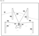
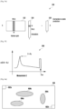
- FIGURE 2A illustrates an example environment 200 in accordance with an embodiment of this disclosure.
- the environment 200 includes an electronic device 210.
- the electronic device 210 can represent the electronic device 100 of FIGURE 1 .
- a portion of the components included in the electronic device 210 can be included in different devices, such as a remote server or multiple devices.
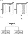
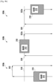
- FIGURE 2B illustrates a diagram 260. in accordance with an embodiment of this disclosure.
- the diagram 260 illustrated example sensor placements on the electronic device 210.
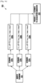
- FIGURE 2C illustrates an example block diagram of an electronic device 210 in accordance with an embodiment of this disclosure.
- the environment 200 illustrates the electronic device 210 within a yard 202.
- the yard as illustrated is a field of grass.
- the electronic device 210 is an automatic lawn mower, which traverses the yard 202 while trimming the grass.
- the environment 200 includes anchor 204a, anchor 204b, anchor 204c, and anchor 204d (which are collectively referred to as anchors 204).
- Information 206a is transmitted between the electronic device 210 and the anchor 204a.
- Information 206b is transmitted between the electronic device 210 and the anchor 204b.
- Information 206c is transmitted between the electronic device 210 and the anchor 204c.
- Information 206d is transmitted between the electronic device 210 and the anchor 204d.
- the electronic device 210 includes a tag 250.
- the tag 250 receives and transmits the information 206a, information 206b, information 206c, and information 206d (which are collectively referred to as information 206) between the anchors 204.
- the electronic device 210 uses the information 206 to generate ranging information from each anchor. For example, the electronic device 210 identifies its location within the yard 202 based on different distances that are identified via the information 206.
- the information 206 can be two-way ranging using UWB ranging.
- UWB two way ranging systems include one or more anchors, such as the anchors 204 that are located at fixed positions within in the yard 202, and one or more tags, such as the tag 250 which is attached to the electronic device 210.
- the UWB ranging generates ranging information indicates the distance between each tag 250 and each of the anchors 204. Therefore, as the electronic device 210 moves throughout the yard 202, the information 206 is used to triangulate and locate the electronic device 210 within the yard.
- other ranging systems like those operating at 60 GHz or using Bluetooth or WiFi can be used.
- the tag 250 can polls for ranging information from the anchors 204.
- the use of multiple tags 250 on the electronic device 210 can increase the heading estimates of the electronic device. For example, each tag can be used to identify its own location heading. Based on the environment, one or more anchors, and/or one or more tags can be blocked from receiving the information 206. As such, using multiple tags 250 and various locations on the electronic device 210, such as illustrated by the electronic devices 210a through 210i can increase the accuracy of the ranging information, since each tag 250 can generate its own ranging information to one or more of the anchors 204.
- the diagram 260 of FIGURE 2B illustrates various quantities, and placement of the tag 250.
- the electronic device 210a includes a tag 250 located in the center front.
- the electronic device 210b includes tags 250 located in the center front and center rear.
- the electronic device 210c includes tags 250 located in a triangular shape and located towards the front.
- the electronic device 210d includes a tag 250 located in in the center rear.
- the electronic device 210e is similar to the electronic device 210b, but the tags 250 are located in the center left and right.
- the electronic device 210f is similar to the electronic device 210c, but the tags 250 are located in a triangular shape and located towards the front.
- the electronic device 210g includes tags 250 located near each corner.
- the electronic device 210h includes four tags 250 while the electronic device 210i includes three tags.
- the electronic device 210 is similar to the electronic device 100 of FIGURE 1 .
- the block diagram of FIGURE 3 illustrates various components of the electronic device 210.
- the electronic device 210 can include sensor 220.
- the sensors 220 can be similar to the sensors 165 of FIGURE 1 .
- the electronic device 210 also includes a drive system 230, a localization generator 240, and an information repository 245.
- the sensors 220 include a first set of sensors 222, a second set of sensors 224, and obstacle avoidance sensors 226.
- the first set of sensors 222 can include one or more IMU's and one or more wheel encoders.
- the first set of sensors 222 are used to identify a location (localization) of the electronic device 210 within the area.
- IMU sensors measure the force, angular rate, orientation of the electronic device using one or more sensors such as an accelerometer, a gyroscope, and the like.
- Wheel encoders are a type of sensor that counts the number of times the motor has rotated. The output of a wheel encoder is used to identify the distance the electronic device 210 has traveled based on each rotation of the motor.
- the second set of sensors 224 can include the tags 250 of FIGURES 2A and 2B .
- the second set of sensors 224 can be used to receive the information 206 from the multiple anchors 204 that are positioned at fixed locations throughout the area.
- the electronic device 210 can generate ranging information based on the information 206. Different sets of ranging information can be generated based on the number of tags, and the ability to communicate with the anchors. For example, the quantity of ranging information could correspond to the number of tags 250 on the electronic device 210.
- the obstacle avoidance sensors 226 can include various sensors to identify the distance between the electronic device 210 and an object within the yard 202.
- the obstacle avoidance sensors 226 can include any number of LiDAR sensors, color cameras, ultrasonic sensors, and the like.
- a new obstacle such as a toy, can be detected via one or more of the obstacle avoidance sensors 226. As such the electronic device 210 can be directed to avoid the object.
- the drive system 230 can include one or more wheels, and motors, that are configured to propel and steer the electronic device 210 throughout the yard 202.
- the drive system 230 can include a two or more wheels that when rotated by a motor or drive mechanism propel the electronic device through the yard 202.
- the motor can include (i) an electric motor supplied power from a battery, or fuel cell, (ii) an internal/external combustion engine powered by an onboard fuel source, (iii) a hydraulic/pneumatic motor powered by an above aforementioned power source, (iv) compressed air, or the like.
- One or more of the wheels swivel to aid navigation or adjustment of yaw of the electronic device 210.
- One or more of the wheels can be provided rotational power individually aid navigation or adjustment of yaw of the electronic device 210.
- the localization generator 240 uses the information from the first set of sensors 222 and the second set of sensors 224 to localize the electronic device 210 within the yard 202.
- the localization generator 240 can fuse the location information from the various sensors to identify the location of the electronic device 210 within the yard 202.
- FIGURE 3A describes the localization generator 240 in greater detail.
- the information repository 245 represents any suitable structure(s) capable of storing and facilitating retrieval of information (such as data, program code, or other suitable information on a temporary or permanent basis).
- the information repository 245 can represent the memory 160 of FIGURE 1 .
- the information repository 245 can be RAM or any other suitable volatile or non-volatile storage device(s).
- the information repository 245 can be persistent storage and contain one or more components or devices supporting longer-term storage of data, such as a ROM, hard drive, Flash memory, or optical disc.
- the information repository 245 includes a generated path plan.
- the path plan can be generated during a training period of the electronic device 210.
- the path plan can include the boundary of the yard, and perinate objects (such as obstacle) that are located within the lawn and are to be avoided.
- the information repository 245 can also indicate the type of boundary.
- a soft boundary can be a boundary between property lines, as such the electronic device 210 can traverse the boundary itself.
- a hard boundary is a boundary that the electronic device should not cross, such as a boundary between the lawn and a body of water. As such, upon detecting a hard boundary, the electronic device 210 stays within the yard a predefined distance from the boundary line.
- the drive system 230 can drive the electronic device along a path within an area.
- the path can include parallel lines that traverse the area.
- the pay can include a spiral.
- a spiral path can start at a center of the area and navigate outwards towards the parameter. Alternatively, a spiral path can start at the boundary of the area and navigate towards the center.
- FIGURE 7A illustrates both a parallel and spiral path.
- FIGURES 2A , 2B, and 2C illustrates the electronic device 210 and its environment
- various changes can be made to FIGURES 2A , 2B, and 2C .
- any other suitable arrangement of the components of the electronic device 210, any number of anchors 204, or any number of location of sensors could be used.
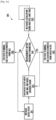
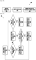
- FIGURE 3A illustrates an example method 300 of obtaining information to identify a location of the electronic device in accordance with an embodiment of this disclosure.
- FIGURES 3B illustrates an example method 310 for identifying the location of the electronic device in accordance with an embodiment of this disclosure.
- FIGURES 3C , 3D , and 3E illustrates example methods 320, 330 and 340, respectively, for fusing the sensor data to identify the location of the electronic device in accordance with an embodiment of this disclosure.
- the methods 300, 310, 320, 330, and 340 can be performed by the electronic device 100 of FIGURE 1 and localization generator of the electronic device 210 of FIGURE 2C .
- methods 300, 310, 320, 330, and 340 are performed by the electronic device 210.
- Embodiments of the present disclosure take into consideration that localization accuracy of the electronic device 210 can decrease due to bad weather conditions, wet lawn, or loss of data due to firmware imperfections these sensors. Additionally, UWB ranging may suffer in non-line of sight (NLOS) scenarios between anchors 204 and the tags 250, which can affect the accuracy of range estimates of the electronic device 210 to the anchors 204. Additionally, the first set of sensors 222 (like IMU or wheel encoders or GPS) which can aid localization have can also yield poor results, such as when one of the wheels is slipping due to a lawn that is wet.
- NLOS non-line of sight
- the localization generator 240, of FIGURE 2C fuses the results from the various sensors 220 together to generate accurate localization estimates with each sensor complementing the shortcomings of the other sensors.
- the localization generator 240, of FIGURE 2C fuses the results from the various sensors 220 together to generate accurate localization estimates with each sensor complementing the shortcomings of the other sensors.
- certain embodiments have multiple UWB tags 250 fixed on the electronic device 210, which could help offer robustness to the heading direction estimate, as discussed in FIGURE 2B , above.
- the method 300 of FIGURE 3A illustrates the localization generator 240 of FIGURE 2C receiving various inputs to identify the location of the electronic device 210.
- the localization generator 240 obtains heading direction via the first set of sensors.
- the localization generator 240 also obtains ranging information from one or more sensors via the second set of sensors.
- the ranging information indicate the location of the electronic device from one or more fixed locations in the area (such as the anchors 204).
- the localization generator 240 can also generate one or more location estimates from the first set of sensors 222, the second set of sensors 224 or the output of a previous localization process. Based on the heading direction, the ranging information, and the one or more location estimates, the localization generator 240 identifies the location and the heading of the electronic device 210.
- wheel encoders can provide to linear velocity while IMU (such as a gyroscope) can provide angular velocity in the motion model. In other embodiments, wheel encoders can provide to angular velocity while an IMU (such as an accelerometer) can provide the linear velocity estimates in the measurement model.
- IMU such as a gyroscope
- IMU such as an accelerometer
- the method 310 of FIGURE 3B illustrates the localization generator 240 of FIGURE 2C continually modifying the location of the electronic device within the area.
- the localization generator 240 predicts the location of the electronic device based on motion.
- the localization generator 240 uses one or more of the first set of sensors 222, such as gyroscopes, wheel encoders, accelerometers, the localization generator 240 predicts the location of the electronic device.
- the localization generator 240 in step 314, then updates the state or pose of the electronic device based on measurements via the ranging information that is obtained from the anchors.
- the updated state is then used in step 312 to further refine and predict a new location of the electronic device based on the motion as detected by the first set of sensors 222.
- the process continues as the electronic device moves throughout the area.
- the localization generator 240 filters the results of the first and second set of sensors 222 and 224 to identify the location of the electronic device.
- a Bayes filter can be used for tracking the electronic device. Syntax (1) describes the process of using the Bayes filter.
- Xt is the state (pose) of the electronic device at time t
- U t are the controls (for instance odometry information)
- Z t are measurements (for instance from GPS or UWB ranging systems).
- the electronic device 210 is in state X is given as bel(X).
- Conditional probability of event A given event B is denoted as p(A
- B). Note that bel(X) p(X t
- ⁇ is a normalizing term to make bel(Xt) as a valid probability distribution.
- models can be used that drive knowledge of p(Z t
- the information obtained from the multiple sensors along with known statistics in their error can be used to come up with knowledge of p(Z t
- the following example is how the knowledge is derived.
- Equation (1) (Xt,Yt) denote X-Y coordinates of the electronic device and ⁇ t is the heading direction at time t with respect to anchor coordinate system. Linear and angular speeds are given by ⁇ ' and ⁇ '.
- the electronic device 210 may not have access to accurate values of the linear and angular speed.
- the motion model maybe approximated as shown in Equation (2).
- N(0, Rt) is Gaussian noise with covariance R t .
- Equation (3) Another possible measurement model for fusing information from GPS and/or UWB ranging is described in Equation (3).
- the vector x y ⁇ is the state of the electronic device
- x a , 1 x a , 2 x a , 3 x a , 4 y a , 1 y a , 2 y a , 3 y a , 4 are anchor locations (assuming there are 4 anchors but could be generalized to any number of anchors) with respect to the same coordinate system as ⁇ and d is the relative placement of the multiple UWB tags on the electronic device.
- N(0, Qt) is Gaussian noise with known covariance Qt.
- T is a known transformation matrix from global world coordinate system to a local coordinate system (used for estimating the electronic device pose).
- the function h () maps he state and other meta information on anchor and tag placement to the measurements.
- UWB ranging measurements r UWB the function computes the true distance of the tags from anchors given electronic device state.
- GPS measurements r GPS the function gives output as just the state itself.
- tags when the electronic device 210 is positioned at location (x, y) , with two tags positioned as follows.
- a pose for the electronic device is described based on vector x y ⁇ , where ⁇ is based on the distance between the first tag to the electronic device (denoted as d1) and the distance between the second tag to the electronic device (denoted as d 2 ).
- the location of tag 1 can be expressed as (x+d 1 cos ⁇ , y+d 1 cos ⁇ ) while the location of tag 2 can be expressed as (x-d 2 cos ⁇ , y-d 2 cos ⁇ ).
- multiple localization processes can run in parallel. By running multiple localization processes in parallel generates the multiple location estimate data 306.
- the multiple location estimate data 306 can be combined for localization of the electronic device 210.
- the ranging information from a first tag 250, the ranging information from a second tag 250, and the GPS signal can be combined to generate a single estimate denoted as p(Z t
- the information from the wheel encoders and IMU can generate an estimate p(X t
- X t is the state and defined by vector x y ⁇
- U2 is defined by the vector ⁇ ⁇ .
- Equation (4) includes multiple equations that describe a process for sensor fusion that employs extended Kalman filter and fuses information from K UWB tags listening to P anchors, any sensor or any other source that directly gives location estimates as measurements (for instance GPS-RTK), and odometer information in terms of linear or angular speed is given as follows.
- Extended Kalman filter is used only for exemplary purpose and the embodiment may be extended to use of particle filters or any other filter like Unscented Kalman filter as well.
- H t ⁇ ⁇ 1,1 ⁇ x ⁇ ⁇ 1,1 ⁇ y ⁇ ⁇ 1,1 ⁇ ⁇ ⁇ ⁇ 1 , P ⁇ ⁇ ⁇ ⁇ 1 , P ⁇ ⁇ ⁇ ⁇ 1 , P ⁇ ⁇ ⁇ ⁇ 2,1 ⁇ ⁇ ⁇ ⁇ 2,1 ⁇ ⁇ ⁇ ⁇ K , P ⁇ ⁇ ⁇ ⁇ K , P ⁇ ⁇ I s is (PK+S) ⁇ 1 matrix with f i,j indicating Euclidean distance of tag i from anchor as a function of the electronic device pose estimate ⁇ x , t ⁇ 1 ⁇ y , t ⁇ 1 ⁇ ⁇ , t ⁇ 1 and anchor locations.
- Is is identity matrix of size S ⁇ S.
- first PK terms correspond to measurement noise for UWB tag 1 from the K anchors followed by UWB tag 2 from the K anchors and so on.
- ⁇ t I ⁇ K t H t ⁇ , where I is an identity matrix return ⁇ t , ⁇ x , t ⁇ y , t ⁇ ⁇ , t
- the parameters that may need on the fly tuning are ⁇ i 2 and ⁇ i 2 .
- Tuning ⁇ i 2 is related to how the information from wheel encoders and IMU are fused together to give linear and angular speed estimates to the localization process.
- the tuning of ⁇ i 2 is related to knowing the quality of range measurement obtained by a tag from each of its sensors. Quality could be quantized by line of sight (LOS) or NLOS scenarios, although not limited thereto.
- LOS line of sight
- NLOS NLOS
- Equation (5) the summation is over the anchor indices and X a,i indicates the anchor locations.
- X denotes the location of the UWB tag that are to be localized.
- function q(A) computes the distance of vector A from the origin and r i are the ranging measurements from different anchors to the tag.
- the loss function l(.) can be just a square operation or it could be any other function. Optimization problem can be solved using standard NLS optimizers like Levenberg Marquardt.
- the location estimates to multiple tags on the electronic device can give a heading direction for the electronic device.
- multiple sensors drive the motion model and the measurement model.
- the IMU and/or the wheel encoders can both drive the motion model. That is, the linear and angular speed information can be made available to the localization process through measurements done using either or both these sensors.
- multiple sensors drive the measurement model - one or multiple UWB two way ranging tags and/or GPS-RTK. This redundancy in providing inputs to the motion and measurement model through the sensors can be used to complement the weakness of each sensor adaptively. For example, wheel encoders are often more accurate for linear motion while IMUs are more accurate for rotational motion.
- velocity estimates v, ⁇ are provided to the localization generator 240, it is be possible to first combine the estimates v wheel , ⁇ wheel and v imu , ⁇ imu to identify the type of motion with high confidence.
- the type of motion can be moving in a straight line versus rotating. This combining operation can change the noise covariance Rt in the motion model.
- the information from the two sensors IMU and wheel encoders can be fused so as to have a small noise covariance.
- the method 320 of FIGURE 3C illustrates an example of how velocity estimated by the wheel encoders and the IMU can be fused together for localization.
- the localization generator 240 identifies a scenario.
- the method 320 describes three scenarios, (scenarios 324a, scenarios 324b, through scenarios 324n), however more or less scenarios can be included in the method 320.
- the scenario 324a indicates that the electronic device 210 is moving in a straight line. Based on the scenario 324a, the function 326a could use the wheel encoder based velocities in the motion model.
- the scenario 324b indicates that the electronic device is rotating. Based on the scenario 324b, the function 326b could use IMU based velocities in the motion model.
- the scenario 324n indicates that the electronic is both rotating and translating.
- the function 326n can take the linear combination of the linear and angular velocity estimates based on both the IMU and wheel encoder. Additionally, more weight can be assigned to the IMU when more rotation occurs. Similarly, more weight can be assigned to the wheel encoders when more translation occurs.
- the corresponding function is used in the localization process by the localization generator 240.
- the identified scenario is scenario 324a
- the linear and angular velocities (v, ⁇ ) of the function 326a is provided to the localization generator 240.
- the identified scenario is scenario 324b
- the linear and angular velocities (v, ⁇ ) of the function 326b is provided to the localization generator 240.
- the method 330 of FIGURE 3D describes identifying an event that indicates that motion data based on IMU (and not wheel encoder) is used for the motion model.
- the electronic device 210 the wheel encoder and IMU motion data are used to generate a single location estimate of the linear and angular velocities.
- the electronic device 210 uses a one-step motion model to generate location estimates of the wheel encoder and IMU separately.
- the electronic device 210 obtains additional motion information, via other sensors such as ranging information (via UWB) and/or GPS.
- step 334 the location estimates of the wheel encoder (of step 332), the location estimates of the IMU (of step 332), the location estimate based on both the IMU and wheel encoder (of step 331), and the location estimates from the other sensors (of step 333) are stored in the information repository 245 of FIGURE 2C .
- the electronic device 210 determines whether a wheel is slipping. For example, if the pose estimates from the wheel encoder overshoots (indicates that the electronic device 210 is further than the other location estimates) the other sensors by a preset threshold over a number of frames, then the electronic device declares that the wheels are slipping.
- the number of frames is the number of estimates that are presented to the decision of step 335. For example, a single estimate may not include enough information to determine whether a wheel is slipping.
- step 336 the electronic device 210 performs the localization using both the wheel encoder and IMU estimates. If the electronic device determines that that the wheel is slipping, then in step 337 the electronic device uses performs localization using IMU based motion instead of incorporating the wheel encoder. That is, in step 337, the electronic device 210 provides linear and angular velocity estimates to the motion model using the motion data form the IMU sensor(s) only.
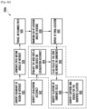
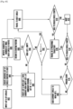
- the method 340 describes using multiple localization processes in parallel and using a combination of different sensors.
- the method 340 uses a single process in default but in response to a triggering event, the localization process will use another process to perform the localization of the electronic device.
- the method 340 describes using multiple localization processes implemented along with a selection criterion for which process to choose when.
- the method 340 describes how to use NLS and filter-based approaches together. Since NLS based localization (step 343) is memoryless and depends only on the current ranging measurements between the anchors 204 and the tags 250, it can start giving reasonable localization output as soon as the mower and sensors are powered up.
- the filter-based approach such as those in steps 341 and 342 usually take some time to initialize. Therefore, the localization process could use NLS based output for better initialization of the filter followed by using the filter in long run. It is noted that sometimes IMU and/or wheel encoders may result in wrong readings due to interaction with environment, in such cases the filter can give a wrong heading or X-Y location predictions. When the IMU and/or wheel encoders provide wrong heading or X-Y location predictions, the NLS can be used as a backup to reinitialize the filter-based localization algorithm.
- step 341 the electronic device 210 initializes the Bays filter based localization process.
- step 342 the electronic device 210 runs the Bays filter based localization process with UWB (ranging information), IMU, and wheel encoder fusion.
- the Bays filter based localization process is described above with respect to Equation (1).
- step 343 the electronic device performs NLS based localization process for multiple UWB tags.
- the NLS based localization process for multiple UWB tags is described above with respect to Equation (5). It is noted that the step 342 and 343 can be performed at or near the same time. this enables the decision of step 344 to compare the results of step 342 with the results of step 343.
- step 344 the electronic device compares the results of steps 342 and 343 to a set of parameters.
- the electronic device determines whether (i) the heading estimates (from the steps 342 and 343) are within predefined degrees, (ii) the location estimates (from the steps 342 and 343) are within a predefined distance, or (iii) the time ⁇ T (from the steps 342 and 343).
- step 345 When the heading estimates are within predefined distance, location estimates within the predefined distance, or time ⁇ T the electronic device, at step 345 performs the path planning using the location estimates from the byes filter of step 342. It is noted that the results of step 344 are provided to the step 342 and used for subsequent iterations of the Bayes filter of step 342.
- step 346 performs the path planning using the location estimates from the step 343. 342. It is noted that the when the path planning uses the location estimates from the step 343, the Bayes filter of Step 341 is re-initialized.
- FIGURES 3A, 3B , 3C , 3D , and 3E illustrates example methods
- various changes may be made to FIGURES 3A, 3B , 3C , 3D , and 3E .
- steps in FIGURES 3A, 3B , 3C , 3D , and 3E could overlap, occur in parallel, or occur any number of times.
- FIGURES 4A and 4B illustrate example methods for sensor updating in accordance with an embodiment of this disclosure.
- FIGURE 4A illustrates the method 400 for adaptive noise variance of UWB for different epochs of the localization process described in FIGURES 3A through 3E .
- FIGURE 4B illustrates the method 410 for adaptive noise variance for sensors of the of the localization process described in FIGURES 3A through 3E based on the timing information.
- Embodiments of the present disclosure take into consideration that all sensor inputs are not available simultaneously as well as the update rate from different sensors may be different. As such, different localization processes can be performed based on the update rate of the sensors and how the information from different sensors is associated for each epoch of the localization processes.
- the method 400 of FIGURE 4A illustrates that the update rate of the UWB ranging is done at 10Hz (step 402) while update rate of the IMU and/or wheel encoders is at 20Hz (step 404). If the wheel encoders and IMU enable reliable relative motion prediction, then running the localization process at 20 Hz can be desirable (step 406). Since fresh UWB measurements are available at every alternate epoch, the noise variance can be adapted for each of the alternate epoch of the localization process.
- the method 410 of FIGURE 4B illustrates that the time of sensor updates can be different.
- the latest sensor 1 measurement can be at time T1 (step 412) while the latest sensor 2 measurement can be at time T2 (step 414).
- the localization process can run at current time T3 (step 416). If the difference between the time T3 and T1 is greater than T (where T is a predetermined value), then a high noise variation for sensor 1 can be used. Alternatively, if the difference between the time T3 and T1 is less than T, then a small noise variance for sensor 1 can be used. Additionally, if the difference between T3 and T2 is greater than T' (where T' is a predetermined value), then a high noise variance for sensor 1 is used. Alternatively, if the difference between the time T3 and T2 is less than T', then a small noise variance for sensor 1 can be used.
- FIGURES 4A and 4B illustrates example methods
- various changes may be made to FIGURES 4A and 4B .
- steps in FIGURES 4A and 4B could overlap, occur in parallel, or occur any number of times.
- FIGURES 5A , 5B, 5C, 5D , 5E, and 5F illustrate example methods for selecting noise variance based on LOS or NLOS.
- FIGURES 5A illustrates an example diagram 500 of an electronic device within an area in accordance with an embodiment of this disclosure.
- FIGURES 5B, and 5C illustrate example methods 510 and 520 for selecting noise variance in accordance with an embodiment of this disclosure.
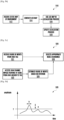
- FIGURE 5D illustrates an example graph 528 for selecting noise variance in accordance with an embodiment of this disclosure.
- FIGURE 5E illustrates an example 530 of partial measurement loss in accordance with an embodiment of this disclosure.
- FIGURE 5F illustrates a graph 540 for accounting of partial measurement loss in accordance with an embodiment of this disclosure.
- the graph 540 describes accounting for partial measurement losses by modifying the measurement model.
- the methods 510 and 520 can be performed by the electronic device 100 of FIGURE 1 and localization generator of the electronic device 210 of FIGURE 2C .
- methods 510 and 520 are performed by the electronic device 210.
- the diagram 500 of FIGURE 5A illustrates a yard with three different lawns, distinguished by zones, such as a main zone 506a, zone A 506b, and zone B 506c, which the electronic device 210 traverses.
- the yard also includes permanent obstacles such as the tree 504a, the tree 504b, the house 504c, and the fence 504d.
- the fence 504d separates the zone A 506b from the zone B 506c.
- a base 503, which is located within the main zone 506a, can be a charging base which charges the electronic device 210, when the electronic device 210 is not traversing the yard 502.
- the base 503 can also protect the electronic device 210 from the elements (rain snow, hail, and the like) when the electronic device 210 is not traversing the yard 502.
- An anchor 508, which is located in the zone B 506c can be similar to the anchors 204 of FIGURE 2A . Due to the fence 504d, electronic device 210 may be unable to receive ranging information from the anchor 508 while in the area 509. That is, due to the height of the fence 504d, the electronic device 210 may have NLOS with the anchor 508, and therefore be unable to obtain ranging information from the anchor 508.
- the electronic device 210 can first identify such regions with a knowledge of the anchor placements. To identify such regions, a line can be traced from the anchor locations to any point on the map and identifying if at least one obstacle intersects this line. The information of the line of sight (LOS)/NLOS conditions for every anchor to each possible pose of the electronic device within the lawn is fed as an input to the localization process dented as LOS map .
- LOS line of sight
- the localization process choses appropriate ⁇ i 2 values for each tag-anchor ranging measurement by selecting noise variance in UWB ranging estimates either as ⁇ LOS 2 or ⁇ NLOS 2 depending on whether the estimated electronic device location has LOS or NLOS links to the anchors based on LOS map .
- the method 510 of FIGURE 5B describes the process generating the static map of the environment to identify both LOS and NLOS areas and then using the LOS and NLOS areas of the static map to improve the localization process described with respect to FIGURES 3A through 3E above.
- the electronic device receives a static map of the environment.
- the static map can be similar to the yard 202 of FIGURE 2A , which shows the location of the base 503, various obstacles (such as the tree 504a, the tree 504b, the house 504c, and the fence 504d), and the anchors (such as anchors 204 of FIGURE 2A and anchor 508 of FIGURE 5A ).
- the electronic device 210 generates a LOS map.
- the LOS map is generated by performing a Ray tracing process.
- the generated LOS map includes a list of all locations on the map with corresponding LOS anchors. That is, the generated LOS map indicates the regions with a LOS to an anchor and regions with NLOS to an anchor (such as the area 509 of FIGURE 5A ).
- step 516 the electronic device 210 uses the generated LOS map in the localization process, which is described above in FIGURES 3A through 3E .
- step 518 the electronic device 210 updates the localization process based on the generated LOS map. For example, if the previous state is Xt then based on the LOS map it is possible to select an appropriate ⁇ i 2 to each anchor for the next step update of the localization process.
- the method 510 is based on a static map, which includes obstacles that do not significantly change over time, such as a structure, tree, fence, and the like. however it is possible that a dynamic object, such as a human walking in the yard could block the LOS between the electronic device 210 and an anchor (such as the anchor 204 of FIGURE 2A and the anchor 508 of FIGURE 5A ). Therefore, due to a dynamic blocking, due to a dynamic object, the ⁇ i 2 as identified in the method 510 may not be accurate in practice. In such cases, the electronic device 210 performs on the fly figure tuning of the noise based on figure of merit that the UWB tag reports. It is noted that not all tags (such as the tags 250) need to include the feature of identify a dynamic blocking.
- the electronic device 210 can identify potential locations of additional anchors to maximize the LOS coverage for the electronic device 210 as it traverses through the yard.
- an anchor 1 is placed to at a location which increases the LOS in the map.
- anchor 2 is placed to overall the LOS coverage of anchor 1 within a minimum distance between anchor 1 and anchor 2.
- the electronic device 210 selects the location that has largest distance to Anchor 1.
- the electronic device sets iAnchor to 3.
- the electronic devices places Anchor iAnchor to increase overlap with LOS coverage of Anchors 1 to iAnchor-1 with a minimum distance D between any two anchors. If there are multiple candidates, pick the one that has largest minimum of all pairwise distances between anchors.
- Set iAnchor iAnchor+1.
- the electronic device record all locations in map m covered by at least K anchors in set ⁇ in the information repository 245 of FIGURE 2C .
- the method 520 of FIGURE 5C describes the process of using the raw channel impulse response of UWB signals to estimate if the signal is LOS or NLOS in real time.
- the electronic device receives a figure of merits from the UWB tags.
- the UWB tags report the figure of merit to the processor (such as the processor 140) of the electronic device 210.
- the electronic device 210 also accesses the raw channel impulse response of a signal from the UWB anchor to the tag.
- the electronic device 210 estimates the figure of merits based on a criterion.
- step 526 the electronic device 210 selects an appropriate noise covariance from either the received figure of merits of step 521 or the estimated figure of merits of the step 524. That is, the localization process selects an appropriate noise covariance for LOS or NLOS based on the figure of merits.
- the graph 528 of FIGURE 5D describes selecting noise variance.
- the electronic device 210 declares the link as LOS. Otherwise the link is NLOS.
- the localization process also addresses partial or total measurement loss from certain sensors.
- FIGURE 5E can be used for the localization process driven by Kalman filters or their variants to addresses partial or total measurement loss from certain sensors.
- the example 530 of FIGURE 5D illustrates addressing a partial measurement loss for a Kalman filter based localization process.
- the example 530 includes a Kalman Gain block 532 is, an innovation block 534, and a correction block 536.
- the term m is the innovation that is missing due to measurement loss.
- the electronic device deletes the mth column in the Kalman Gain block 532 and the mth row in the innovation block 534 for the particular iteration of the Kalman filter (or variants) to generate the correction block 536.
- FIGURES 5A through 5F illustrates example methods
- various changes may be made to FIGURES 5A through 5F .
- steps in any of the methods of FIGURES 5B and 5C could overlap, occur in parallel, or occur any number of times.
- FIGURES 6A , 6B , 6C , 6D , 6E , and 6F describe the process of the electronic device 210 planning a path within an area.
- the area can be in indoor area (such as an area used by an autonomous vacuum cleaner or an autonomous mop), an outdoor area (such as an area used by an autonomous lawn mower), or a pool (such as an area used by an automatic pool cleaner).
- the electronic device 210 identifies a path that enables the electronic device 210 to move over all of the desired points within a given area.
- FIGURE 7A illustrates example paths within various areas. That is the electronic device 210, first generates a path to traverse the area within a border while avoiding known obstacles.
- FIG. 6A , 6B , 6C , 6D , 6E , and 6F describe the process of the electronic device 210 planning a path within an area and traversing around previously unknown obstacles and attempting to traverse the previously missed areas at a later time.
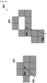
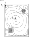
- FIGURE 6A illustrates an example area 600 with obstacles in accordance with an embodiment of this disclosure.
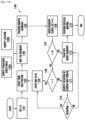
- FIGURES 6B and 6C illustrate example methods 605 and 610 for traversing the area in accordance with an embodiment of this disclosure.
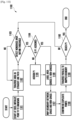
- FIGURE 6D illustrates an example method 630a for identifying unmowed regions in accordance with an embodiment of this disclosure. It is noted that the method 630a could be included in the method 610 of FIGURE 6C .
- FIGURE 6E illustrates an example unmowed area according to the method of FIGURE 6D in accordance with an embodiment of this disclosure.
- FIGURE 6F illustrates an example method 660a to travel the unmowed locations in accordance with an embodiment of this disclosure. It is noted that the method 660a could be included in the method 610 of FIGURE 6C .
- the methods 605, 610, 630a, and 660a can be performed by the electronic device 100 of FIGURE 1 and localization generator of the electronic device 210 of FIGURE 2C .
- methods 605, 610, 630a, and 660a are performed by the electronic device 210.
- the area 600 of FIGURE 6A illustrates an example lawn with multiple permanent obstacles.
- the area 600 can be a yard such as the diagram 500 of FIGURE 5A , or an area that is inside a building such as a home or office complex.
- the electronic device 210 is able to traverse the area 600 from a start position 602a to an end position 602b while traversing as much of the area as possible. After the electronic device travels throughout the area 600 and arrives at the end position 602b, the electronic device 210 can identify patches that were not traversed, such as the unmowed areas 604a, 604b. and 604c, before returning to the docking/home station (such as the base 503 of FIGURE 5A . The unmowed areas 604a, 604b.
- the unmowed areas 604a, 604b. and 604c can be caused by a localization error which causes the electronic device to miss traversing a certain portion of the area 600.
- the unmowed areas 604a, 604b. and 604c can be caused by a dynamic obstacle, such as a toy that was left in the area 600, an animal (such as a pet or livestock) or human that is located in the area 600.
- the dynamic obstacle can be an object that is detected by the obstacle avoidance sensors 226 of the FIGURE 2C . That is, the dynamic obstacle is an object that is not located in a in the area 600 during the training phase of the area 600 such as a structure, tree, or shrubbery.
- the electronic device 210 identifies the shortest possible path (the minimum path length) to go from the current electronic device position (end position 602b) to the start position 602a while visiting all the unmowed areas 604a, 604b. and 604c. That is, after the electronic device 210 arrives at the end position 602b and identifies the unmowed areas 604a, 604b. and 604c. Then, the electronic device 210 identifies and travels the shortest path between its current location and its docking/home location while visiting each of the identified unmowed areas 604a, 604b. and 604c. It is noted, that the location and shape of the unmowed areas can differ from one another as illustrated) in FIGURE 6A .
- the electronic device 210 visits an unmowed area, there is a possibility that the dynamic obstacle still persists making it not possible to mow (traverse) the unmowed regions even after another attempt.
- the mowing time can be reduced which can increase the battery life of the electronic device and the anchors 204.
- the method 605 of FIGURE 6B illustrates a high-level method that the electronic device operates while performing path coverage to identify and revisit any missed areas.
- the electronic device 210 drives on a planned path. That is, the electronic device 210 traverses the area 600 from the start location 602 to the end position 602b and avoids any known obstacles.
- the electronic device 210 identifies missed areas (step 607).
- the missed area are locations that the electronic device did not cover while it traversed the area 600.
- the electronic device generates a new path to traverse the missed areas. That is, the electronic device 210 re-plans a path the visit and traverse the identified missed areas.
- the method 610 of FIGURE 6C provides detailed description of the method 605 of FIGURE 6B .
- the electronic device 210 starts to travel on a planned path. However, while traveling on its planned path the electronic device 210 may encounter a dynamic obstacle. If the dynamic obstacle persists for more than a time threshold, then the electronic device 210 re-plans its path to go around the obstacle.
- the electronic device 210 keeps a track of its location all the time it navigates. After reaching the finishing position, it computes an estimate of the unmowed regions in the lawn using the Method 630a of FIGURE 6D . For instance, the electronic device 210 can identify, based on its historical location, a number of discounted unmowed regions, such as the region as illustrated in FIGURE 6E .
- the electronic device 210 may flag an unmowed region as potentially permanent obstacle or temporary based on other sensors. For instance, a camera image may show the obstacle is a human, in which it is likely to move away in some time. If a camera image shows a heavy object placed on the lawn, like furniture the chances of it moving are less.
- the output of method 630a could also be circle centers with corresponding radius and an associated quality indicator Q, which indicates how likely is the obstacle to move away.
- the electronic device 210 starts to travel on a planned path. For example, the electronic device 210 starts from the start position 602a and traverses the area 600 in parallel lines or a spiral, while avoiding known obstacles.
- the electronic device 210 determines whether an unknown obstacle (such as a dynamic obstacle) is blocking its path. When the electronic device 210 determines that an unknown obstacle is blocking its path, the electronic device 210 continues to traverse the area 600 on its originally planned path, in step 622. Alternatively, when the electronic device 210 determines that an unknown obstacle is blocking its path, in step 616, the electronic device 210 waits for a predetermined period of time.
- an unknown obstacle such as a dynamic obstacle
- the electronic device determines in step 618 whether the obstacle is still obstructing the path. For example, if the obstacle is an animal, the electronic device may spook the animal causing it to move off of the original path. If the object did not move, in step 620, the electronic device 210 modifies the originally planned path the avoid the obstacle. That is, the electronic device 210 modifies the original planed path to account for the new obstacle. As such, avoiding the obstacle creates a missed area. If the object moved, then in step 622, the electronic device 210 continues to traverse the area 600 on its originally planned path.
- the electronic device 210 determines whether it is at the finished position such as the end position 602b of FIGURE 6A , based on its current location. When the electronic device 210 is not at the finish position, returning to step 614, the electronic device 210 determines whether an obstacle is blocking the planned path which is preventing the electronic device 210 from moving forward. Alternatively, upon determining that the electronic device 210 is at the finish position, in step 630 the electronic device 210 identifies the unmowed areas (the areas that were missed due to a dynamic obstacle or poor localization). For example, based on the localization process, the electronic device 210 identifies portions of the area 600 that were missed, such as the unmowed areas 604a, 604b, and 604c.
- the method 630a of FIGURE 6D describes the process of identifying the areas that were missed due to a dynamic obstacle or poor localization.
- the electronic device 210 generates a new path to visit the unmowed areas (the areas that were missed due to a dynamic obstacle or poor localization).
- the method 660a of FIGURE 6F describes the process of generating the new path.
- the method 630a of FIGURE 6D describes the process of identifying the missed areas of the step 630 of FIGURE 6C .
- the electronic device 210 identifies the boundary of a region of interest, which could be the perimeter of the area 600 of FIGURE 6A .
- the electronic device 210 generates a path within the area of interest. The generated path could be parallel lines or a spiral. The generated path avoids known obstacles.
- the electronic device 210 travels on the planned path, similarly to the step 612 of FIGURE 6C . While traveling on the planned path, the electronic device 210 maintains a log of its location and/or heading. The maintained log could be for all time epochs between the start of its run until arriving at the end location at step 640.
- the electronic device 210 pixilates the map of the area into a grid, to identify cells (or pixels) of the grid that were traversed and cells that were not traversed.
- the grid size can be fixed or vary based on the localization accuracy.
- the electronic device 210 identifies the accuracy of the localization process (step 642).
- the localization process can indicate localization accuracy based on the quality of inputs it receives from the different sensors.
- the electronic devise pixilates the area into a grid of dimension D, which is based on the size of the grid is based on the accuracy of the localization process of step 642.
- the grid size may be small and if the localization accuracy is poor then the grid size can be larger.
- the grid size is variable as it can change from one run to the next run based on the localization accuracy.
- the step 642 is omitted from the method 630a. As such in step 644 the size of each grid is fixed to a predetermined size.
- the electronic device 210 flags each cell based on its location.
- the cells can be flagged as traversed (the electronic device 210 traveled over this cell and therefore the cell corresponds to an area that is mowed).
- the cells can be flagged as not traversed (the electronic device 210 did not travel over this cell, or partially traveled over the cell, and therefore the cell corresponds to an area that is missed or not mowed).
- the electronic device clusters the cells that touch each other into an unmowed region.
- the electronic device identifies the centroid and radius of each cluster.
- FIGURE 6E illustrates a cluster 652a and a cluster 652b.
- the clusters 652a and 652b are made up of multiple cells indicating locations that the electronic device 210 did not travel or partially traveled over.
- the electronic device 210 is able to identify the centroid 654a of the cluster 652a and the centroid 654b of the cluster 652b. Based on the position of the centroid within a cluster, the electronic device 210 also identifies the radius which is the distance from the centroid to the outside perimeter of the cluster.
- the radius 656a is the distance from the centroid 654a to the outside of the cluster 652a.
- the radius 656b is the distance from the centroid 654b to the outside of the cluster 652b.
- the method 660a of FIGURE 6F describes the process of generating a new path to visit the unmowed areas of the step 660 of FIGURE 6C .
- the electronic device 210 receives an input list of missed areas.
- the input list can include a list of Q circles that were not traversed or partially traversed by the electronic device.
- the list can be generated by the method 630a of FIGURE 6D , and each circle within the list corresponds to a cluster of cells that were identified and corresponds to a missed area.
- step 664 the electronic device 210 creates or generates a list of circle centers to re-visit.
- the electronic device 210 uses a solution to the Traveling Salesman Problem (TSP) to create an ordered list of circle centers to visit from its current location to its home location (such as the starting position 602a or the docking/ home location).
- TSP Traveling Salesman Problem
- the docking/ home location initiates a counter of the number of times each circle is visited.
- the electronic device 210 travels to a circle.
- the circle could be the shortest distance from its current location.
- the electronic device 210 determines whether it can reach the center of the circle, as indicated by the radius and centroid which were identified in step 650 of FIGURE 6C . If the electronic device is able to reach the center of the circle, then in step 676, the electronic device 210 travels in a predefined trajectory. For example, the electronic device can travel from the center of the circle in a spiral that increases in size until it reaches the outer perimeter of the circle, such that the circle is fully traversed (and mowed).
- step 670 the electronic device 210 determines that it is unable to reach the center of the circle
- step 672 the electronic device 210 waits for a predetermined period of time. After the period of time expires, the electronic device 210 in step 674 determines whether it can reach the center of the circle, as indicated by the radius and centroid which were identified in step 650 of FIGURE 6C . If the electronic device is able to reach the center of the circle, then in step 676, the electronic device 210 travels in a predefined trajectory. For example, the electronic device can travel from the center of the circle in a spiral that increases in size until it reaches the outer perimeter of the circle, such that the circle is fully traversed (and mowed).
- step 680 After determining that a triggering event (of step 678) did not occur, when the electronic device 210 in step 680, includes the current circle to a new list L.
- the electronic device 210 also initializes the visit counter ni, and increases the value of M (which was set to zero in step 666) by one.
- the electronic device 210 After the electronic device 210 travels in a predefined trajectory within the circle (step 676), the triggering event occurs (step 678), or after the current circle is added to a new list L (step 680), the electronic device 210 in step 682, determines whether the variable i is less than or equal to n.
- the variables i and n were set in step 666. When the variable i is less than or equal to n, then the variable i is increased by 1, and the method returns to step 668, and the electronic device 210 travels to the next circle. Alternatively, if the variable i is greater than n, the electronic device 210, in step 684, determines whether the new list L (which was created in step 680) is empty.
- step 688 the electronic device 210 travels to the home position, such as the start position 602a.
- the electronic device 210 in step 686, resets the list Q with the list L, such that N is set to M.
- the electronic device then initiates a new empty list L of unmowed regions and sets the value of M to zero and the value of i to 1.
- the electronic device 210 returns to step 664 to generates a new list of circle centers to re-visit. This list is based on the circles that were identified in the method 630a but not previously visited in step 676.
- FIGURE 6F describes using a TSP to come up with the initial order of the list of unmowed areas.
- a finite time Markov decision process MDP or any other process can be used to come up with a strategy to visit the unmowed regions instead of an process that solves traveling salesman problem (TSP) to come up with an initial order of the list of unmowed areas.
- TSP traveling salesman problem
- the electronic device 210 waits longer as per T(n) to check if the obstacle moves away this time. Note that T(n) need not necessarily be an increasing function of n and maybe a constant.
- a variation to the method 660a can be as follows. If a visit to a circle is obstructed, instead of appending the circle to the list of unmowed circles, the electronic device 210 may create a new list of unvisited circles at the end of attempting to visit each circle in original list. Then one may re-optimize the order in which to visit the unmowed circles in the new list using TSP or MDP or any other algorithm and follow the order in the next attempt to visit these circles.
- state variable x k can represent location of the electronic device 210 in terms of its X-Y coordinates on the lawn.
- State variable U k can represent a list of unmowed regions in space (for instance, circle centers as an outcome of method 630a of FIGURE 6C .
- the electronic device 210 is at some location x 0 with N unmowed regions in space denoted by a list U 0 .
- the electronic device 210 has to attempt to visit all unmowed regions in a finite horizon MDP formulation, such that after N time steps (equal to the number of unmowed regions in space).
- Action u k ⁇ U k at time k is decision to visit a particular unmowed region in space (u k represents the next location to visit).
- the cost of making action u k while in state x k is given by g(x k , u k , w k ) where w k is a random variable capturing randomness in the environment (for instance, in spite of taking a decision to visit region u k the electronic device 210 may not be able to reach there or may have to deal with other uncertainties before reaching the position).
- the function could also be a function of quality Q k associated with an action u k , which indicates how likely is it that the unmowed region k will likely still be obstructed and unavailable for mowing.
- Equation (5) and Equation (6) below describes the final cost g N (x N ) may represent the cost to go back to home position or the docking station from the last visited unmowed region in space.
- the operator E indicates expectation over the randomness in the model given by w i . Note that the optimization variables are u,...,u (N-1) which indicate the order in which we visit the N unmowed regions in space.
- Equation (7) describes a finite horizon MDP formulation modified based on this disclosure.
- FIGURES 6A through 6F illustrate example methods and diagrams
- various changes may be made to FIGURES 6A through 6F .
- steps in any of the methods of FIGURES 6B, 6C , 6D , and 6F could overlap, occur in parallel, or occur any number of times.
- FIGURE 7A illustrates example path plans 700 in accordance with an embodiment of this disclosure.
- the area 702a illustrates various obstacles 704 that the electronic device 210 navigated around.
- the obstacles can be dynamic obstacles or known obstacles.
- the electronic device 210 starts at location S and travels a path 704a throughout the area 702a, until it reaches the location F. It is noted that the electronic device 210 does not revisit any of the obstacles 704 after reaching the location F.
- the area 702b illustrates the electronic device 210 navigating in a spiral along path 704b. That is, the electronic device 210 first traverse the parameter of the area 702b and then in a spiral motion travels towards the center.
- the area 702c illustrates the electronic device 210 navigating along parallel lines along the path 704b. It is noted that the distance between the lines of the path 704b is denoted by the distance ⁇ 706a and the distance between the lines of the path 704c is denoted by the distance ⁇ 706b.
- Embodiments of the present disclosure enable the electronic device to automatically change the distance ⁇ such as shown in FIGURES 7B and 7C , or manually changed by an outside source, such as a user in order to ensure the electronic device 210 does not miss areas, as described in FIGURES 8A and 8B , below.
- FIGURES 7B and 7C illustrate example methods 710 and 720 for identifying localization accuracy in accordance with an embodiment of this disclosure.
- the methods 710 and 720 can be performed by the electronic device 100 of FIGURE 1 and localization generator of the electronic device 210 of FIGURE 2C .
- methods 710 and 720 are performed by the electronic device 210.
- the methods 710 and 720 describe using an adaptive ⁇ based on the localization accuracy estimated by the electronic device 210.
- the electronic device 210 sets a smaller value for ⁇ , resulting in the denser paths, if the localization accuracy is bad, and set a larger value for ⁇ ,resulting in sparser paths if the localization accuracy is good. It is noted that having just two possible values of ⁇ is just given as an example and there can be multiple states in which ⁇ can be quantized.
- the method 710 of FIGURE 7B illustrates how the localization accuracy is identified which is used to select of value for ⁇ .
- the electronic device 210 performs three separate localization processes (localization process 712a, localization process 712b, and localization process 712m), such the localization processes described above. More or less localization processes can be performed.
- step 714 the electronic device 210 performs a point cloud location estimates and heading direction from the localization process 712a, localization process 712b, and localization process 712m.
- step 716 the electronic device 210 classifies the X-Y point cloud as good or bad. Also, in step 716, the electronic device 210 classifies the heading direction as good or bad.
- the electronic device 210 classifies the point cloud as good if both X-Y and heading point cloud is good.
- the electronic device estimates a final localization output. For example, the electronic device 210 estimates the final localization output based on the different models and uses the output for the path planning process with a selected of value for ⁇ which is based on whether the point cloud is classified as good or bad (step 716).
- the method 720 of FIGURE 7C is a more detailed example of the method 710 of FIGURE 7B .
- the electronic device 210 performs four separate localization processes (localization process 722a, localization process 722b, localization process 722c, and localization process 722d), such the localization processes described above.
- the localization process 722a can be based on UWB ranging with K tags and a wheel encoder.
- the localization process 722b can be based on UWB ranging with K tags and IMU.
- the localization process 722c can be based on UWB ranging with K tags.
- the localization process 722d can be based on UWB ranging with K tags, IMU, and wheel encoders.
- step 724 the electronic device 210 performs a point cloud location estimates and heading direction from the localization process 722a, localization process 722b, and localization process 722c, and localization process 722d.
- step 726 the electronic device 210 determines whether k > L min models provide difference in heading direction with ⁇ . If the models are not within ⁇ ⁇ , then in step 728, the electronic device 210 identifies the final estimate of the heading direction as a mean of the k heading directions. Then, in step 738 the electronic device 210 selects a large value for ⁇ .
- step 730 the electronic device selects a heading estimate from one of the models according to a criterion C head and selects a small value for ⁇ .
- step 732 determines whether at least K > L min models provide difference in X-Y estimates less than a threshold distance. If the models are within the threshold distance, then in step 734, the electronic device 210 identifies the final estimate of the X-Y location as a mean of the K locations. Then, in step 738 the electronic device 210 selects a large value for ⁇ . Alternatively, if the models are larger than the threshold distance, then electronic device 210 selects the location estimates from one of the models according to a criterion C Loc and selects a small value for ⁇ .
- (1) select the process used in previous time step of the localization process.
- (2) select a process based on a model wherein the smallest mean of diagonal entries in Qt.
- (3) select a process based on a model wherein the smallest mean of diagonal entries in Rt.
- (4) select a process based on a model wherein the smallest mean of diagonal entries in Qt and the smallest mean of diagonal entries in Rt.
- (6) select a process that uses a selected subset of sensors.
- FIGURES 7A through 7C illustrate example methods and diagrams
- various changes may be made to FIGURES 7A through 7C .
- steps in any of the methods of FIGURES 7B and 7C could overlap, occur in parallel, or occur any number of times.
- FIGURES 8A and 8B describe the process of changing the density of the paths.
- the FIGURE 8A illustrates the method 800 for user assistance for modifying a path in accordance with an embodiment of this disclosure.
- the method 800 can be performed by the electronic device 100 of FIGURE 1 and localization generator of the electronic device 210 of FIGURE 2C .
- method 800 is performed by the electronic device 210.
- FIGURE 8B illustrates an example modified path plan based on the method 800 of FIGURE 8A in accordance with an embodiment of this disclosure.
- an outside source can instruct the electronic device 210 to reduce the value of ⁇ in a certain area in order to increase the density of the paths.
- the outside source could be a human, that through a user interface modifies the value of ⁇ .
- the outside source could be a camera or other sensors on the electronic device 210 which can identify unmowed regions.
- the electronic device 210 traverses the area.
- the electronic device can be an automatic lawn mower, which traverses a yard and trims the grass of the lawn.
- a human or a sensor on the electronic device 210 can inspect the lawn to identify any unmowed regions. For example, as shown in the lawn 808a, the electronic device 210 travels along the path 802a.
- the area 804a is the unmowed region which can be identified by a user or the electronic device 210 itself.
- the electronic device 210 modifies its path to include a denser path in the designated area due to localization accuracy loss in the designated areas. For instance, if there is unmowed region near location (x 0 ,y 0 ) then the electronic device 210 may perform an extra spiral or an extra back and forth motion in such areas to cover the unmowed region. For instance, as shown in the lawn 808b, the electronic device 210 travels along the path 802b.
- the path 802b is modified version of the path 802a since the path 802b includes an extra pass as indicated in the area 806a.
- FIGURES 8A and 8B illustrate example methods and diagrams
- various changes may be made to FIGURES 8A and 8B .
- steps in any of the method of FIGURE 8B could overlap, occur in parallel, or occur any number of times.
- FIGURES 9A , 9B , and 9C describe the process of path planning along the border (or parameter) of the lawn.
- FIGURE 9A illustrates an example method 900 for path planning based on boundary type in accordance with an embodiment of this disclosure.
- FIGURE 9B illustrates an example path based on a soft boundary in accordance with an embodiment of this disclosure.
- FIGURE 9C illustrates an example path based on a hard boundary in accordance with an embodiment of this disclosure.
- the method 900 can be performed by the electronic device 100 of FIGURE 1 and localization generator of the electronic device 210 of FIGURE 2C . For ease of explanation, method 900 is performed by the electronic device 210.
- the electronic device 210 when the electronic device 210 is an automatic lawn mower, owing to the dimensions of the electronic device 210 and the placement of the blade, it may not be possible to completely mow the grass close to the boundaries.
- some boundaries could be adjacent properties that include grass to be cut (such as a neighbor), such that no harm occurs if the electronic device 210 crosses the boundary.
- some boundaries could be a flower bed, a body of water (such as a pool, river, lake, and the like) which if the electronic device 210 cross, could cause harm to landscape or the electronic device 210 itself. Therefore, embodiments of the present disclosure provide system and methods for distinguishing between boundary types.
- the electronic device 210 identifies the boundary type.
- a sensor like camera on the electronic device 210 can identify some boundaries as hard, which indicates that the electronic device 210 cannot go outside these boundaries. For instance, if a camera detects a fence or water outside the lawn area, it declares corresponding boundary patches as strict. However, there could also be loose boundaries. For instance, outside the lawn space, it could just be flat land or soil or pavement. If a sensor like camera is able to identify this, then it marks these regions as loose boundaries in space. In this case, the electronic device 210 may plan its path to go outside the boundary so it mows the regions close to the boundary of the lawn efficiently.
- FIGURES 9B and 9C illustrates an of planned paths with hard and soft boundaries.
- step 904 when the electronic device 210 identifies a soft boundary, then the electronic device 210 does not have to explicitly perform more complicated motion patterns to mow areas close to the boundaries. For example, the electronic device 210 can traverse along the boundary line.
- step 906 when the electronic device 210 identifies that a hard boundary, then the electronic device 210 has to explicitly perform more complicated motion patterns to mow areas near the boundaries. For example, the electronic device 210 can traverse within the lawn near the boundary line.
- FIGURE 9B illustrates the electronic device 210 traversing along a path and encounters a soft boundary.
- the electronic device 210 includes a blade 212, which is used to trim the grass. It is noted that the blade 212 could be a suction port for sucking up dirt and debris.
- the FIGURE 9B illustrates three different time instances, that of time 910a, 910b, and 910c.
- the electronic device 210 is traveling along the path 912 and detects a boundary 914 which crosses the path 922.
- the electronic device 210 identifies that the boundary 914 is a soft boundary.
- the electronic device 210 modifies the path 912 to path 912a and then travels along the boundary.
- the electronic device 210 continues on the return path.
- FIGURE 9C illustrates the electronic device 210 traversing along a path and encounters a hard boundary.
- the electronic device 210 includes a blade 212, which is used to trim the grass. It is noted that the blade 212 could be a suction port for sucking up dirt and debris.
- the FIGURE 9C illustrates two different time instances, that of time 920a and time 920b. First at time 920a, the electronic device 210 is traveling along the path 922 and detects a boundary 924 which crosses the path 922. Then at time 920b, the electronic device 210 identifies that the boundary 924 is a hard boundary. Upon identifying that the boundary 924 is a hard boundary, the electronic device 210 modifies the path 922 to path 922a. The path 922a remains a predefined distance inside the lawn from the boundary 924.
- FIGURES 9A , 9B , and 9C illustrate example methods and diagrams
- various changes may be made to FIGURES 9A , 9B , and 9C .
- steps in any of the method of FIGURE 9A could overlap, occur in parallel, or occur any number of times.
- FIGURES 10A , 10B, and 10C describe power efficient coverage path planning in accordance with an embodiment of this disclosure.
- FIGURE 10A illustrates an example power consumption graph 1000 in accordance with an embodiment of this disclosure.
- FIGURE 10B illustrates an example block diagram 1010 of components of a sensor in accordance with an embodiment of this disclosure.
- FIGURE 10C illustrates an example method 1020 for power saving triggering events in accordance with an embodiment of this disclosure.
- the method 1020 can be performed by the electronic device 100 of FIGURE 1 and localization generator of the electronic device 210 of FIGURE 2C .
- method 1020 is performed by the electronic device 210.
- the electronic device 210 modifies the duty cycle of sensors used for localization, to the performs power efficient coverage path planning. For example, some off-the-shelf ultra-wideband (UWB) two way ranging sensors have battery life that lasts for a day if it is operating all day. If such UWB transceivers are used for localization of electronic devices for coverage path planning tasks, the battery life is not convenient since the batteries would have to change the batteries every day. Therefore, embodiments of the present disclosure provide a power saving mode for the UWB anchors which are used for localization.
- UWB ultra-wideband
- FIGURE 10A illustrates a graph 1000 which describes a typical power consumption of a sensor participating in two way ranging system as a tag/anchor. As illustrated in this example, the power consumption is significantly smaller in deep sleep mode as compared an idle period or actively transmitted or receiving information.
- the block diagram 1010 of FIGURE 10B describes the power management system 1012 of the electronic device 210.
- the power management system 1012 communicates with various functions/sensors such as a Bluetooth transceiver (other radio control to configure the device manually handling communication interfaces like SPI (serial port interfaces) or running any other user specific applications) 1016a, a UWB radio UWB radio and MAC control 1016b (i.e. controlling whether to activate the UWB transceiver for two way ranging protocol), a user application 1016c, a localization engine 1016d (similar to the localization generator 240 of FIGURE 2 ), a wired/wireless communication interface 1016e.
- a Bluetooth transceiver other radio control to configure the device manually handling communication interfaces like SPI (serial port interfaces) or running any other user specific applications
- UWB radio UWB radio and MAC control 1016b i.e. controlling whether to activate the UWB transceiver for two way ranging protocol
- a real time clock (RTC) 1014 in the power management system 1012 may instruct to the functions/sensors 1016a through 1016e to switch off.
- RTC 1014 is always ON but a deep sleep mode can result in significant power savings since the functions/sensors 1016a through 1016e are powered down.
- wake-up mode all the functionalities 1016a through 1016e can be active.
- the RTC 1014 in a power saving mode, enables a periodic deep sleep mode of the functions/sensors 1016a through 1016e followed by a wake-up time.
- the electronic device 210 can instruct one or more of the anchors to enter a power savings mode, which intentionally introduces measurement losses, in order to increase the battery life of the anchors 204, since the localization process, described above, can handle information loss. For example, when the electronic device 210 is located on the opposite side of the yard than a portion of the anchors, the electronic device 210 can transmit a message to the near anchors to instruct the far anchors to enter a power savings mode. In another embodiment, when the electronic device 210 is located on the opposite side of the yard than a portion of the anchors, the electronic device 210 can transmit a message to those anchors instructing those anchors to enter a power savings mode.
- FIGURE 10C illustrates the method 1020 that describes triggering the power saving mode for an anchor based on some criterion C. It is noted that the power saving can be obtained by changing the duty cycle of the sensors as indicated in FIGURE 10B .
- the electronic device 210 can identify one or more triggering events/criteria, such as the triggering event 1024a, the triggering event 1024b, and the triggering event 1024c.
- the triggering event 1024a can be when the UWB tags are powered down and the electronic device 210 is not actively mowing the lawn.
- the triggering event 1024b can be when the distance between the tag(s) and the anchor(s) are larger than a threshold.
- the triggering event 1024c can be when the distance between the electronic device 210 and an anchor is less than a threshold.
- the electronic device 210 can instruct anchor A to enter a power savings made 1 and notify the other anchors to go into power savings mode 1026a.
- the RTC 1014 enables deep sleep mode of a predefined time followed by a wakeup command in a cycle.
- the electronic device 210 can instruct anchor A to notify other anchors to go into power savings mode 1026b.
- the RTC 1014 enables deep sleep mode of a mode of a predefined time followed by a wakeup command in a cycle. It is noted that the predefined times can differ between the power savings mode 1026a and the power savings mode 1026b.
- the electronic device 210 can instruct anchor A to go into a performance efficient mode 1026c and notify the other anchors to also go into the performance efficient mode 1026c.
- the RTC 1014 enables deep sleep for a predefined time that is larger than the predefined time of the power savings mode 1026a and the power savings mode 1026b, followed by a wakeup command in a cycle
- the triggering events can be identified by the anchors themselves.
- the anchor A in response to the anchor A detecting the triggering event 1024a, the anchor A notifies the other anchors to enter the power saving mode 1026a and also goes into a power saving mode 1026a.
- the anchor A in response to the anchor A detecting the triggering event 1024b, the anchor A notifies certain other anchors to go into a power saving mode 1026b.
- the anchor A goes into the performance efficient mode 1026 and notifies the other anchors to also go into the performance efficient mode 1026c as well.
- the criterion C can be based on the distance the anchor is from the electronic device 210.
- the electronic device 210 can identify the distance between the tags 250 and the anchors 204. The electronic device 210 can then determine that the distance to one or more of the anchors is beyond a threshold distance. Upon determining that the distance from the electronic device 210 to one or more of the anchors is beyond a threshold distance, the electronic device can transmit to any of the anchors 204 a message indicating that a certain anchor is to enter a power savings mode.
- the criterion C can be based on whether the electronic device 210 (or in general all electronic devices with registered tags on the UWB TWR network) is powered down or if the electronic device 210 is powered up but the electronic device 210 does not perform a predefined function (such as mowing), then all anchors can be in power saving mode
- the criterion C can be based a schedule. For example, if the electronic device 210 is scheduled to mow the lawn every day at a certain time and finish mowing by a certain time. any other time outside that window the anchors automatically go in deep sleep mode.
- FIGURES 10A , 10B, and 10C illustrate example methods and diagrams
- various changes may be made to FIGURES 10A , 10B, and 10C .
- steps in any of the method of FIGURE 10C could overlap, occur in parallel, or occur any number of times.
- FIGURES 11A-11L describe various embodiments for boundary and obstacle detection in accordance with an embodiment of this disclosure.
- FIGURES 11A and 11B illustrate example methods 1100a and 1100b for mapping an area in accordance with an embodiment of this disclosure.
- FIGURE 11C illustrates an example of an area 1110 with multiple sections with a seed point in accordance with an embodiment of this disclosure.
- FIGURE 11D illustrates an example diagram 1115 of an electronic device identifying certain areas in accordance with an embodiment of this disclosure.
- FIGURE 11E illustrates an example diagram 1120 of the electronic device performing both boundary and obstacle mapping based on a spiral pattern in accordance with an embodiment of this disclosure.
- FIGURES 11F illustrates an example diagram 1125 for detecting the boundary of the area in accordance with an embodiment of this disclosure.
- FIGURES 11G illustrates an example diagram 1128 for detecting obstacles in accordance with an embodiment of this disclosure.
- FIGURE 11H illustrates an example method 1130 for boundary and obstacle mapping in accordance with an embodiment of this disclosure.
- FIGURE 11I illustrates an example method 1140 for obstacle mapping in accordance with an embodiment of this disclosure.
- FIGURES 11J , 11K , and 11L illustrate example methods 1150, 1160, and 1180 for boundary mapping in accordance with an embodiment of this disclosure.
- the methods 1100a, 1100b, 1130, 1140, 1150, 1160, and 1180 can be performed by the electronic device 100 of FIGURE 1 and localization generator of the electronic device 210 of FIGURE 2C .
- methods 1100a, 1100b, 1130, 1140, 1150, 1160, and 1180 is performed by the electronic device 210.
- Embodiments of the present disclosure take into consideration that the coverage path planning in electronic devices (such as an autonomous lawn mower, an autonomous vacuum cleaner, an autonomous mop, and the like) involves coming up with a path such that the electronic devices are made to move over all desired points in space.
- An example coverage path planning is boustrophedon or back?and-forth path planning such as the path 706c of FIGURE 7A .
- the electronic device 210 travels in deterministic patterns to cover the entire area 702c of FIGURE 7A .
- the electronic device 210 should be aware of the boundary of the lawn and the location of permanent or static obstacles.
- the simplest way to determine the lawn boundary is to manually measure the boundary.
- Another common practice is wire installation on the lawn boundary that aids detection of edges.
- the electronic device 210 learns the boundary of the lawn and location of permanent obstacles before planning the motion without the installation of additional sensors or wires along the boundary of the lawn.
- automatic lawn mapping can be done by performing outside boundary mapping and permanent obstacle mapping at the same time, as described in the method 1100a of FIGURE 11A . In certain embodiments, automatic lawn mapping can be done by dividing the steps of the method 1 100a into sequential steps, that of identifying the outside boundary and then detecting and mapping the permanent obstacles in the lawn, as described in the method 1100b of FIGURE 11B .
- the method 1100a describes the process of automatic lawn mapping by performing outside boundary mapping and permanent obstacle mapping at the same time.
- the electronic device 210 starts driving from a start position.
- the start position can be referred to as a seed or seed position.
- driving the electronic device 210 in step 1102, maintains a predefined path, such as a back and forth path (the path 706c of FIGURE 7A ) or a spiral path (the path 706b of FIGURE 7A ).
- the electronic device 210 while driving and maintaining the predefined path, the electronic device 210, in step 1103, performs both boundary mapping and obstacle mapping.
- the method 1130 of FIGURE 11H discussed in greater detail below, further describes the method 1100a.
- the electronic device 210 performs boundary and obstacle mapping during a single predefined path.
- electronic device 210 starts at the seed of the lawn. It follows a pattern, which can be spiral or a back and forth pattern.
- the location of the electronic device 210 can be estimated using a sensor or fusion of sensors, for example, ultra-wide band (UWB), inertial measurement units (IMU) and wheel encoders.
- UWB ultra-wide band
- IMU inertial measurement units
- wheel encoders While following the pattern the electronic device 210 detects obstacles using additional sensors such as LiDAR or camera.
- traveling the electronic device 210 performs the method 1140 of FIGURE 11I and described in the diagram 1128 of FIGURE 11G . to go around the obstacle and resume the patterned path.
- the electronic device 210 approaches a boundary, it follows the path parallel to the boundary based on the method 1160 of FIGURE 11K and the diagram 1125 of FIGURE 11F until it is able to resume the pattern.
- the method 1100b describes the process of automatic lawn mapping by performing outside boundary mapping and then performing the obstacle mapping.
- the electronic device 210 starts driving from a start position.
- the start position can be referred to as a seed or seed position.
- the electronic device 210 travels to a boundary of the area.
- the electronic device 210 maps the outside boundary. For example, the electronic device 210 travels around the perimeter of the area.
- the electronic device 210 generates a path inside the boundary.
- the generated path could be path could be a back and forth path (the path 706c of FIGURE 7A ) or a spiral path (the path 706b of FIGURE 7A ).
- the electronic device 210 then travels along the generated path and performs permanent obstacle mapping inside the area.
- the electronic device 210 performs boundary and obstacle mapping separately.
- the boundary mapping is performed first, followed by obstacle mapping.
- boundaries can be identified by starting the electronic device 210 at a seed and using a sensor to distinguish between the lawn and non-lawn areas and then making the electronic device 210 follow a path parallel to the detected boundary.
- the electronic device 210 After performing a closed loop boundary detection, the electronic device 210 performs permanent obstacle mapping by navigating the electronic device 210 within the detected boundary of the lawn and avoiding the obstacles that come in the way while mapping those onto the grid map.
- each section can be mapped individually, in which case the user can specify the seed points of each section of the lawn, as shown in FIGURE 11C .
- the electronic device 210 starts at a seed point in the lawn, such as the seed 1112 and 1114 of FIGURE 11C .
- the seed point can be any area on the lawn which is specified by the user via a user interface (UI).
- the electronic device 210 then maps each section individually.
- the electronic device 210 can either be physically moved to or near another seed point of another section of the yard by the user or if there is a clear path between the seed points of different sections of the yard, the electronic device 210 can plan a path and rely on localization to navigate to the seed of the next section of the yard.
- boundary detection is performed using a sensor which can distinguish between the lawn and non-lawn areas.
- a camera can be used to identify the area in the field of view 1116 as grass 1117 or non-grass 1118, as shown in FIGURE 11D .
- Some ways of labeling the area as grass 1117 or non-grass 1118 can be hue detection on camera images or some machine learning solutions.
- Other sensors that can be used for this are light sensors or ultrasonic radar sensors.
- the boundary can be detected using camera or light sensors.
- a user can manually define the boundaries on the User Interface (UI). For example, the partially defined region is displayed on the graphical user interface (GUI) and the user draws the unclear boundary on the GUI.
- GUI graphical user interface
- the electronic device 210 can then directly mark that boundary on the grid map based on the user input before starting to map rest of the boundary edges.
- the boundary detection process is repeated with different patterns in the multiple runs to converge to a grid map.
- the first run can be based on spiral pattern
- the next run can use a square pattern and so on, until convergence is obtained.
- Convergence can be obtained when the difference between a new run and a previous run is below a threshold.
- the diagram 1120 of FIGURE 11E illustrates an example run based on a spiral pattern starting from a seed position 1123.
- the electronic device 210 starting from the seed position 1123 starts in a small circle which expands to include the entire lawn.
- the electronic device 210 avoids the obstacles 1122a and 1122b and then resumes the path until it teaches the finish position at location 1121.
- the diagram 1125 of FIGURE 11F describes the process of following the boundary of an area 1127.
- the process of the diagram 1125 can be implemented to do path tracking using feedback controllers such as proportional-integral-derivation controller (PID), linear-quadratic regulator controller (LQR), model predictive controller, pure pursuit controller, etc.
- PID proportional-integral-derivation controller
- LQR linear-quadratic regulator controller
- model predictive controller model predictive controller
- pure pursuit controller can be used to control the steering angle of mower to track a path.
- Equation (8) The speed of electronic device 210 is v(t) and the steering speed ⁇ can be described in Equation (8).
- L d is a look-ahead distance from the current position to the desired path
- k is a proportional control gain
- ⁇ is the orientation error between the heading of electronic device 210 and the look-ahead vector (g x ,g y ).
- ⁇ t arctan 2 l d sin ⁇ k ⁇ t
- the electronic device 210 maps the permanent or static obstacles, as illustrated in diagram 1128 of FIGURE 11G . That is, the diagram 1128 describes the process of mapping permanent or static obstacles. For example, the electronic device 210 plans a path within the mapped boundary and traverses along the planned path. Whenever the electronic device 210 encounters an obstacle, it goes around the obstacle based on the processes as described in the diagram 1128 of FIGURE 11G while mapping it onto the grid map. After mapping the obstacle, the electronic device 210 re-plans the path to go around the obstacle from the current location to the end point.
- the process for mapping permanent or static obstacles can be implanted using artificial potential filed (APF), D*, artificial neural network, and the like.
- the distance between obstacles and electronic device 210 can be measured using ranger sensors such as camera, LiDAR, ultrasonic sensors, and the like.
- the sum of the attractive force from a goal waypoint and the repulsive forces from obstacles will drive the electronic device 210 to avoid obstacles and move to the desired goal waypoint.
- Equation (9) describes the attractive force F att (x,t).
- k a is a proportional gain
- x(t) is the current location of electronic device 210
- x d (t) is the position of the goal waypoint.
- Equation (10) describes the repulsive force F rep (x,t).
- F rep the repulsive force
- k r is a proportional gain
- ⁇ is the distance between the electronic device 210 and the obstacle
- ⁇ 0 is the limit distance of potential filed influence
- x is the current position of the electronic device 210
- x 0 is the position of shortest obstacle.
- the sum of F att , of Equation (9), and F rep , of Equation (10), decides the desired orientation of the electronic device 210.
- the method 1130 of FIGURE 11H describes in detail the method 1100a of FIGURE 11A , which the electronic device 210 performs both boundary and obstacle mapping during the same run.
- the electronic device 210 generates a pattern path starting from a seed position.
- the electronic device 210 maps the boundary in a grid map. To map the boundary, in step 1133a the electronic device 210 identifies the grass and non-grass areas and in step 1133b, the electronic device 210 identifies its current location within the lawn.
- the electronic device 210 determines whether it detects an obstacle.
- step 1135 the electronic device 210 follows the boundary of the obstacle based on the process described in the diagram 1128 of FIGURE 11G . thereafter, in step 1138, the electronic device 210 resumes the motion of the planned path.
- the electronic device 210 compares its current distance to a boundary to a threshold. For example, when the distance between electronic device 210 and the boundary is less than the threshold, the electronic device 210 in step 1137 follows the boundary based on the process described in the diagram 1125 of FIGURE 11F . When the distance between electronic device 210 and the boundary is greater than the threshold, the electronic device 210 in step 1138 resumes the motion of the path.
- the electronic device 210 determines, in step 1139, whether the boundary is closed. After determining that the boundary is not closed, the electronic device 210 returns to step 1134. Alternatively, after determining that the boundary is closed, the electronic device 210 saves the generated grid map which includes the boundary and the static obstacles.
- the method 1140 of FIGURE 11I , the method 1150 of FIGURE 11J , the method 1160 of FIGURE 11K , and the method 1180 of FIGURE 11L describes the process of identifying the boundary and obstacles separately, similar to the method 1100b of FIGURE 11B .
- the electronic device 210 identifies the obstacles within the boundary based on the method 1140.
- the method 1140 of FIGURE 11I describes the process of identifying obstacles within an area after the boundary is identified. For example, after performing boundary mapping, the electronic device 210 plans a path inside the obtained boundary based on any path planning solution, described above. While navigating through that path, electronic device 210 can map the permanent obstacles in the lawn based on the method 1140. It is noted that for automatic mapping of lawn boundaries and permanent obstacles, it is important to ensure that the lawn is free of any temporary obstacles, such as toys, animals, and the like to prevent them from being mapped as permanent obstacle.
- the permanent obstacle avoidance can be iterative to avoid obstacles by running the electronic device on the planned path multiple times until a stable map is obtained. This will ensure removal of static obstacles in the map if they exist.
- step 1141 the electronic device 210 obtains the previously generated boundary mapping and then plans a path inside the obtained boundary.
- step 1142 the electronic device 210 traverses the planned path.
- step 1143 the electronic device 210 determines whether an obstacle is detected. When an obstacle is not detected, the electronic device 210, in step 1146, continues on its planned path.
- the electronic device 210 in step 1144, follows the boundary of the obstacle while mapping it in the grid map. the electronic device 210 can follow the obstacle using the process described above in FIGURE 11G .
- the electronic device 210 in step 1145, replaces a path from its current location to the finish point. The electronic device 210 the continues on the re-planned path in step 1146.
- step 1147 the electronic device 210 determines whether it arrived at the finish location. If the electronic device 210 arrived at the finish location, the obstacle mapping is complete. Alternatively, if the electronic device 210 did not arrived at the finish location, the electronic device 210 determines whether an obstacle is detected in step 1143 and repeats the steps until the electronic device 210 arrived at the finish location.
- the method 1150, 1160, and 1180 of FIGURE 11J , 11K , and 11L describes the process of identifying the boundary.
- the method 1150 of FIGURE 11J uses cameras or other sensors to identify the area in the field of view as grass or non-grass.
- the location of the electronic device 210 can be estimated using a sensor or fusion of sensors. Based on the current location and separation between the grass and non-grass areas on the image, the boundary of the lawn can be marked in the grid map.
- the electronic device 210 then follows the mapped boundary based on the process described in FIGURE 11F and go around the boundary to map the entire lawn boundary.
- step 1151 starts driving from a seed position and maps.
- the electronic device 210 maps the boundary in a grid map. To map the boundary, in step 1153a the electronic device 210 identifies the grass and non-grass areas and in step 1153b, the electronic device 210 identifies its current location within the lawn.
- the electronic device 210 travers the mapped boundary based on the process described in FIGURE 11F .
- the electronic device 210 determines whether the boundary is closed. When the boundary is not closed, the electronic device 210 returns to step 1152 to map the boundary. Alternatively, when the boundary is closed, electronic device 210 plans a path inside the identified boundary.
- the electronic device 210 performs obstacle mapping. In certain embodiments, the obstacle mapping is based on the method 1140 of FIGURE 11I .
- the method 1160 of FIGURE 11K describes a variation of the method 1150 when the sensor that is providing location estimates is not very accurate, or when the labeling of grass and non-grass areas has uncertainties.
- the method 1160 is an iterative method. That is, the map obtained in each iteration of the method 1160 is stored and compared to the map obtained in the previous iteration. If the two maps deviate from each other, the process continues until the maps converge.
- step 1161 electronic device 210 sets a variable, i, to zero.
- step 1162 the electronic device 210 starts driving from a seed position and maps.
- step 1164 the electronic device 210 maps the boundary in a grid map. To map the boundary, in step 1163a the electronic device 210 identifies the grass and non-grass areas and in step 1163b, the electronic device 210 identifies its current location within the lawn.
- step 1165 the electronic device 210 travers the mapped boundary based on the process described in FIGURE 11F .
- step 1166 when the boundary is closed, the electronic device 210 sets the value of i, to i+1.
- step 1167 the electronic device determines whether the value of i is less than the value of N. When the value of i is greater than or equal to the value of N, then in step 1172, the electronic device 210 plans a path inside the identified boundary.
- the electronic device 210 determines whether the value of i is less than one. When the value of i is greater than or equal to the one, then the electronic device 210 in step 1171, identifies a deviation of the current map from M. In step 1170, the electronic device 210 determines whether the deviation is greater than a threshold. When the deviation is greater than the threshold or when the value of i is less than one, the electronic device 210, in step 1169, stores the map as map M. After storing the map, the electronic device 210 returns to the start position at step 1162.
- the electronic device 210 After planning the path inside the boundary, in step 1172, the electronic device 210, in step 1173, performs obstacle mapping.
- the obstacle mapping is based on the method 1140 of FIGURE 11I .
- the method 1180 of FIGURE 11L describes a variation of the that can be used in addition to the methods 1150 and 1160.
- the method 1180 describes when and how to map the boundary.
- the electronic device 210 follows predefined line path (such as straight line) until it comes close to the boundary.
- the boundary is detected using camera or other sensors. Whenever the electronic device 210 is at a distance, x, from the boundary, it marks that point as the start point for mapping and starts to follow a path parallel to the boundary. While mapping the points onto the grid map, the electronic device 210 also performs a scan matching of the currently obtained boundary points with the already mapped point in order to avoid any redundancies or thickening of the boundaries. This enables the electronic device 210 to close the loop upon reaching the start point again. The electronic device 210 continues to map the boundary, perform scan matching and moving parallel to the boundary until it reaches the start point after traversing the perimeter.
- step 1181 the electronic device 210 starts from a seed point and initialize a point P1 to unknown.
- step 1182 the electronic device 210 travels in a straight line path.
- step 1183 the electronic device 210 determines whether a non-grass area is detected at a predefined distance from the electronic device 210. When a non-grass area is not detected, the electronic device 210, continues to travel in a straight line path, of step 1182. When a non-grass area is not detected within a predefined distance from the electronic device 210, in step 1184, the electronic device 210, determines whether P1 is assigned. If P1 is not assigned, in step 1185, the electronic device 210 assigns the current location of the electronic device 210 as P1.
- the electronic device 210 After assigning the current location as P1, or determining that P1 is already assigned, the electronic device 210, in step 1186, labels the area in the field of view as grass or non-grass. In step 1187, the electronic device 210 uses the location estimates along the labeled area to map the boundary between the grass and non-grass on the grid map. In step 1188, the electronic device 210 confirms the number of duplicate points. For example, the electronic device 210 performs a scan matching of the new map points labeled as boundary points to the previously mapped points to ensure there is no duplication of points letting to extended boundaries. In step 1189, the electronic device 210 travers parallel to the mapped boundary. In step 1190, the electronic device 210 determines whether it reached the point P1. When the electronic device 210 reaches the point P1 the boundary detecting process concludes. Alternatively, when the electronic device 210 does not reach the point P1, the method returns to step 1183.
- FIGURES 11A through 11L illustrate example methods and diagrams
- various changes may be made to FIGURES 11A through 11L .
- steps in any of the methods 1100a, 1100b, 1130, 1140, 1150, 1160, and 1180 could overlap, occur in parallel, or occur any number of times.
- FIGURE 12 illustrates an example method 1200 for controlling an electronic device in accordance with an embodiment of this disclosure.
- the methods 1100a, 1100b, 1130, 1140, 1150, 1160, and 1180 can be performed by the electronic device 100 of FIGURE 1 and localization generator of the electronic device 210 of FIGURE 2C .
- methods 1200 is performed by a processor, such as the processor 140 the electronic device 210.
- step 1202 the processor 140 generates a path to drive the electronic device within the area.
- the electronic device includes additional sensors for detecting obstacles.
- the processor 140 determines whether the obstacle blocks the path. in response to a determination that the obstacle blocks the path, the processor 140 controls the electronic device to stop driving for a predetermined period of time. In response to a determination that the obstacle did not move after the predetermined period of time, the processor 140 modifies the path to avoid the obstacle in order to resume on the path.
- the processor 140 controls the electronic device to drive within the area from a start location to an end location according to the path. Upon reaching the end location, the processor 140 identifies one or more areas that were not traversed. The processor 140 the generates a new path drive the electronic device to traverse the one or more areas that were not traversed.
- the processor 140 can also identify missed areas after the electronic device traverses an area. For example, the processor 140 generates a map of the area, based on the location and the trajectory of the electronic device as the electronic device traverses the area. In response to the electronic device arriving at the end location, the processor 140 divides the map into a plurality of cells. The processor 140 provides a first flag to a first portion of the plurality of cells that correspond to portions of the map that the electronic device traversed and provides a second flag to a second portion of the plurality of cells that correspond to the one or more areas that were not traversed, the second flag identifies missed regions. The processor 140 then clusters the missed regions into circles of different radius and.
- the processor 140 can also control the electronic device to revisit the missed regions. For example, the processor 140 generates a list of the missed regions in the area to determine an order in which the missed regions are visited by the electronic device. The processor 140 controls the electronic device to drive to a center position of a first missed region that is included in the list based on the determined order. In response to a determination that the electronic device is located at the center position of the first missed region, the processor 140 control the electronic device to drive in a predefined trajectory through the first missed region.
- the processor controls the electronic device to drive the electronic device to another missed region of the missed regions included in the list based on the determined order or control the electronic device to drive the electronic device to the end location, upon a detection of a triggering event.
- the processor 140 receives the motion information from the first set of sensors.
- the first set of sensors can include an IMU and a wheel encoder.
- the motion information includes linear velocity and angular velocity.
- the processor 140 In step 1206, the processor 140 generate ranging information.
- the ranging information is based on the information that is received from multiple anchors, via a second set of sensors.
- the anchors are positioned at fixed locations throughout an area, such as a yard.
- step 1208 while the electronic device 210 is driven along the path, the processor 140 identifies a location and heading direction within the area of the electronic device based on the motion information.
- the processor 140 identifies a first distance traveled based on the motion information from the wheel encoder sensor, a second distance traveled based on the motion information from the inertial measurement sensor, and a third distance traveled based on the ranging information from the second set of sensors (via the step 1208). If the first distance traveled is larger than either the second distance traveled or the third distance traveled, the processor, identifies that the location and the heading direction of the electronic device based on the inertial measurement sensor and the second set of sensors while not using the wheel encoder sensor.
- processor 140 modifies the location and the heading direction of the based on the ranging information.
- the processor 140 identifies a first location of the electronic device within the area based on the first set of sensors and the second set of sensors. While the first location is identified, the processor 140 identifies a second location of the electronic device within the area based on the second set of sensors. The processor 140 then compares a difference between a first attribute based on the first location and a second attribute based on the second location to a threshold, wherein the first and second attributes are headings, locations, or times. The processor then determines whether to use the first location or the second location based on the comparison.
- processor 140 controls the electronic device to drive within the area according to the path, based on the location and the heading direction of the electronic device.
- the processor 140 can identify a boundary type of the boundary line based on a sensor.
- the sensor can be a camera and a grass detector.
- the processor 140 controls the electronic device to drive the electronic device over and along the boundary line.
- the processor 140 controls the electronic device to drive the electronic device a threshold distance from the boundary line within the area.
- the processor 140 controls the electronic device, via a drive system to drive along a perimeter of the lawn and generate a grid map of the lawn. After the grid map is generated, the processor 140 controls the drive system to drive the electronic device within the perimeter of the lawn along a predefined path. In response to a determination that an obstacle blocks the predefined path, the processor 140 controls the drive system to drive the electronic device around the obstacle.
- the obstacle can be a static or dynamic obstacle. When the obstacle is static, the location of the obstacle is used when generating the path of step 1202. While the drive system drives the electronic device around the obstacle, the processor 140 includes the obstacle in the grid map. After the drive system drives the electronic device around the obstacle, the processor 140 control the drive system to resume driving the electronic device along the predefined path within the perimeter of the lawn.
- the processor 140 can perform a power management function with respect to the anchors. For example, the processor 140 can identify a distance between the second set of sensors and each of the multiple anchors. The processor 140 then determines that the distance between the second set of sensors and a one or more of the multiple anchors is larger than a threshold distance. The processor 140 can then transmit, to at least one of the multiple anchors, a message indicating that the one or more anchors are to enter or exit a power saving mode.
- FIGURE 12 illustrates example methods and diagrams, various changes may be made to FIGURE 12 .
- steps in any of the method 1200 could overlap, occur in parallel, or occur any number of times.
- the user equipment can include any number of each component in any suitable arrangement.
- the figures do not limit the scope of this disclosure to any particular configuration(s).
- figures illustrate operational environments in which various user equipment features disclosed in this patent document can be used, these features can be used in any other suitable system.
Description
- This disclosure relates generally to an autonomous robot and method of control of the autonomous robot. More specifically, this disclosure relates to mapping and localization of an autonomous lawn mower.
- Autonomous robots that perform household functions such as floor cleaning, pool cleaning, and lawn cutting are now readily available consumer products. Autonomous robots can be programmed to mow lawn areas. A robotic lawn mower is an autonomous robot that is used to cut lawn grass. Care must be taken to keep such robots from mowing outside intended areas as well as avoiding permanent and dynamic obstacles within the area to be mowed.
US 2016/349362 A1 relates to a navigation device for an autonomous vehicle.WO 2019/068175 A1 discloses determination of pose of an autonomous vehicle with respect to a defined area of operation.US 6 377 888 B1 discloses a system for controlling movement of a free-ranging vehicle on a surface. - Embodiments of the present disclosure provide systems and methods for controlling an electronic device. In certain embodiments, an electronic device is an automatic lawn mower that traverses an area and trims the grass, a floor cleaner (such as a vacuum cleaner or a mop) that traverses an area to collect dirt and debris, or a pool cleaner that traverses an area to collect dirt and debris. The electronic device can perform coverage path planning by identifying a trajectory as the electronic device traverses through an area. It is noted that the area can be a yard which includes a lawn. For example, the lawn is the area of grass within the yard. The yard can also include areas that do not include grass, and which are to be avoided by the automatic lawn mower, such as a tree, flower beds, bodies of water, drop offs due to abrupt changes in elevation, and the like. The automatic lawn mower can identify a coverage path, which permits the electronic device to traverse the lawn in order to trim the grass of the lawn, while avoiding the areas of the yard that are not to be traversed.
- This disclosure provides sensor fusion for localization and path planning.
- The invention is set out in the appended set of claims.
- Other technical features may be readily apparent to one skilled in the art from the following figures, descriptions, and claims.
- Before undertaking the DETAILED DESCRIPTION below, it may be advantageous to set forth definitions of certain words and phrases used throughout this patent document. The term "couple" and its derivatives refer to any direct or indirect communication between two or more elements, whether or not those elements are in physical contact with one another. The terms "transmit," "receive," and "communicate," as well as derivatives thereof, encompass both direct and indirect communication. The terms "include" and "comprise," as well as derivatives thereof, mean inclusion without limitation. The term "or" is inclusive, meaning and/or. The phrase "associated with," as well as derivatives thereof, means to include, be included within, interconnect with, contain, be contained within, connect to or with, couple to or with, be communicable with, cooperate with, interleave, juxtapose, be proximate to, be bound to or with, have, have a property of, have a relationship to or with, or the like. The term "controller" means any device, system or part thereof that controls at least one operation. Such a controller may be implemented in hardware or a combination of hardware and software and/or firmware. The functionality associated with any particular controller may be centralized or distributed, whether locally or remotely. The phrase "at least one of," when used with a list of items, means that different combinations of one or more of the listed items may be used, and only one item in the list may be needed. For example, "at least one of: A, B, and C" includes any of the following combinations: A, B, C, A and B, A and C, B and C, and A and B and C.
- Moreover, various functions described below can be implemented or supported by one or more computer programs, each of which is formed from computer readable program code and embodied in a computer readable medium. The terms "application" and "program" refer to one or more computer programs, software components, sets of instructions, procedures, functions, objects, classes, instances, related data, or a portion thereof adapted for implementation in a suitable computer readable program code. The phrase "computer readable program code" includes any type of computer code, including source code, object code, and executable code. The phrase "computer readable medium" includes any type of medium capable of being accessed by a computer, such as read only memory (ROM), random access memory (RAM), a hard disk drive, a compact disc (CD), a digital video disc (DVD), or any other type of memory. A "non-transitory" computer readable medium excludes wired, wireless, optical, or other communication links that transport transitory electrical or other signals. A non-transitory computer readable medium includes media where data can be permanently stored and media where data can be stored and later overwritten, such as a rewritable optical disc or an erasable memory device.
- Definitions for other certain words and phrases are provided throughout this patent document. Those of ordinary skill in the art should understand that in many if not most instances, such definitions apply to prior as well as future uses of such defined words and phrases.
- According to embodiments of the present disclosure the electronic device performs path planning and then traverses the planned path, such that very little area is of the lawn is not traversed. According to embodiments of the present disclosure the electronic device also performs a coverage path planning which uses minimal battery. According to embodiments of the present disclosure the electronic device is able to distinguish between different types of boundaries and can navigate the boundaries accordingly. According to embodiments of the present disclosure the electronic device can also identify, and navigate around new obstacles, such as a pet that is lying in the pre-identified coverage path.
- Embodiments of the present disclosure enable the electronic device to localize itself with the area. Localization includes both the X-Y coordinate location and the heading direction of the electronic device. In certain embodiments, localization and heading direction are identified using multiple sensors. Example sensors include, but not limited to, two way ranging systems (such as ultra-wide band (UWB) frequencies), global positioning system (GPS), wheel encoders, and inertial measurement units (IMUs). The data from the various sensors can be fused together for generated localization estimates. Additionally, data from different localization models can be used together to generate improved location estimates. In certain embodiments, anchors, such as a fixed infrastructure, can be played throughout the yard to improve the localization accuracy with two way ranging systems, such as the UWB two-way ranging. Embodiments of the present disclosure also include methods for modifying certain types of coverage path planning based on estimate of localization accuracy that is obtained by using the different localization formulations possible with multiple sensors.
- Additionally, embodiments of the present disclosure describe generating a path plan that directs the electronic device to cover an increased area of the yard in a reduced time. Additionally, by reducing the time the electronic device travers the area, can effectively increase longevity of the anchor batteries. Embodiments of the present disclosure also describe methods to extend the longevity of anchor batteries in addition to reducing the operating time of the electronic device. For example, based on one or more triggering events, embodiments of the present disclosure include system and methods for placing anchors into power saving modes to increase the batteries of the anchors (if the anchors are powered by batteries, instead of receiving electricity directly from an electronical grid).
- Each time the electronic device avoids dynamic obstacles (a new obstacle), it may not traverse a certain area. For example, when the electronic device is an automatic lawn mower, when the automatic lawn mower avoids a previously unknown obstacle, (such as when an animal or a human or a new flower garden is detected along the coverage path), the automatic lawn mower may leave some areas unmowed. As such, embodiments of the present disclosure provide systems and methods for mowing all the unmowed areas due to dynamic obstacles or path tracking failure at the end of the originally planned path. For example, the automatic lawn mower may use a finite horizon Markov Decision Process or a solution to the traveling salesman problem in order to re-plan paths to the unmowed areas.
- Embodiments of the present disclosure also provide systems and methods for mowing the areas close to the boundary. In certain embodiments, different types of boundaries can be identified by the electronic device. Based on the type of boundary the electronic device can determine to traverse the boundary line itself or remaining within the boundary (and not crossing the boundary line).
- Moreover, embodiments of the present disclosure provide system and methods for generating a planned path based on gathering information about the area itself, such as boundaries, and location of permanent obstacles. To generate a path that traverses the area, the electronic device first generates an initial map of the area. To generate the initial map of the area, the electronic device identifies the outside boundary as well as the locations of permanent obstacles that are within the boundary. The boundary of the area is the outside perimeter of the lawn (which prevents the electronic device from crossing into a separate property). Obstacles can include trees, bushes, decorative rocks, sculptures, fixtures, flower beds, bodies of water, and the like, which the electronic device is either unable to or directed to avoid traversing over. In certain embodiments, the electronic device can identify the boundary of the area without using a fence or sensors located along the boundary itself.
- For a more complete understanding of the present disclosure and its advantages, reference is now made to the following description taken in conjunction with the accompanying drawings, in which like reference numerals represent like parts:
-
FIGURE 1 illustrates an example electronic device in accordance with an embodiment of this disclosure; -
FIGURE 2A illustrates an example environment including an electronic device and anchors in accordance with an embodiment of this disclosure; -
FIGURE 2B illustrates example sensor placements on the electronic device in accordance with an embodiment of this disclosure; -
FIGURE 2C illustrates an example block diagram of an electronic device in accordance with an embodiment of this disclosure; -
FIGURE 3A illustrates an example method of obtaining information to identify a location of the electronic device in accordance with an embodiment of this disclosure; -
FIGURES 3B illustrates an example method for identifying the location of the electronic device in accordance with an embodiment of this disclosure; -
FIGURES 3C ,3D , and3E illustrates example methods for fusing the sensor data to identify the location of the electronic device in accordance with an embodiment of this disclosure; -
FIGURES 4A and4B illustrate example methods for sensor updating in accordance with an embodiment of this disclosure; -
FIGURES 5A illustrates an example diagram of an electronic device within an area in accordance with an embodiment of this disclosure; -
FIGURES 5B and 5C , illustrate example methods for selecting noise variance in accordance with an embodiment of this disclosure; -
FIGURE 5D illustrates an example graph for selecting noise variance in accordance with an embodiment of this disclosure; -
FIGURE 5E illustrates an example of partial measurement loss in accordance with an embodiment of this disclosure; -
FIGURE 5F illustrates a graph for accounting of partial measurement loss in accordance with an embodiment of this disclosure; -
FIGURE 6A illustrates an example area with obstacles in accordance with an embodiment of this disclosure; -
FIGURES 6B and 6C illustrate example methods for traversing the area in accordance with an embodiment of this disclosure; -
FIGURE 6D illustrates an example method for identifying unmowed regions in accordance with an embodiment of this disclosure; -
FIGURE 6E illustrates an example unmowed area according to the method ofFIGURE 6D in accordance with an embodiment of this disclosure; -
FIGURE 6F illustrates an example method to travel the unmowed locations in accordance with an embodiment of this disclosure; -
FIGURE 7A illustrates example path plans in accordance with an embodiment of this disclosure; -
FIGURES 7B and7C illustrate example methods for identifying localization accuracy in accordance with an embodiment of this disclosure; -
FIGURE 8A illustrates an example method for user assistance for modifying a path in accordance with an embodiment of this disclosure; -
FIGURE 8B illustrates an example modified path plan based on the method ofFIGURE 8A in accordance with an embodiment of this disclosure; -
FIGURE 9A illustrates an example method for path planning based on boundary type in accordance with an embodiment of this disclosure; -
FIGURE 9B illustrates an example path based on a soft boundary in accordance with an embodiment of this disclosure; -
FIGURE 9C illustrates an example path based on a hard boundary in accordance with an embodiment of this disclosure; -
FIGURE 10A illustrates an example power consumption graph in accordance with an embodiment of this disclosure; -
FIGURE 10B illustrates an example block diagram of components of a sensor in accordance with an embodiment of this disclosure; -
FIGURE 10C illustrates an example method for power saving triggering events in accordance with an embodiment of this disclosure; -
FIGURES 11A and11B illustrate example methods for mapping an area in accordance with an embodiment of this disclosure; -
FIGURE 11C illustrates an example of an area with multiple sections with a seed point in accordance with an embodiment of this disclosure; -
FIGURE 11D illustrates an example diagram of an electronic device identifying certain areas in accordance with an embodiment of this disclosure; -
FIGURE 11E illustrates an example diagram of the electronic device performing both boundary and obstacle mapping based on a spiral pattern in accordance with an embodiment of this disclosure; -
FIGURES 11F illustrates an example diagram for detecting the boundary of the area in accordance with an embodiment of this disclosure; -
FIGURES 11G illustrates an example diagram for detecting obstacles in accordance with an embodiment of this disclosure; -
FIGURE 11H illustrates an example method for boundary and obstacle mapping in accordance with an embodiment of this disclosure; -
FIGURE 11I illustrates an example method for obstacle mapping in accordance with an embodiment of this disclosure; -
FIGURES 11J ,11K , and11L illustrate example methods for boundary mapping in accordance with an embodiment of this disclosure; and -
FIGURE 12 illustrates an example method for controlling an electronic device in accordance with an embodiment of this disclosure. -
FIGURES 1 through 12 , discussed below, and the various embodiments used to describe the principles of the present disclosure in this patent document are by way of illustration only and should not be construed in any way to limit the scope of the disclosure. Those skilled in the art will understand that the principles of the present disclosure may be implemented in any suitably-arranged system or device. - Embodiments of the present disclosure provide systems and methods for controlling an electronic device. In certain embodiments, an electronic device is an automatic lawn mower that traverses an area and trims the grass, a floor cleaner (such as a vacuum cleaner or a mop) that traverses an area to collect dirt and debris, or a pool cleaner that traverses an area to collect dirt and debris. The electronic device can perform coverage path planning by identifying a trajectory as the electronic device traverses through an area. It is noted that the area can be a yard which includes a lawn. For example, the lawn is the area of grass within the yard. The yard can also include areas that do not include grass, and which are to be avoided by the automatic lawn mower, such as a tree, flower beds, bodies of water, drop offs due to abrupt changes in elevation, and the like. The automatic lawn mower can identify a coverage path, which permits the electronic device to traverse the lawn in order to trim the grass of the lawn, while avoiding the areas of the yard that are not to be traversed.
- According to embodiments of the present disclosure the electronic device performs path planning and then traverses the planned path, such that very little area is of the lawn is not traversed. According to embodiments of the present disclosure the electronic device also performs a coverage path planning which uses minimal battery. According to embodiments of the present disclosure the electronic device is able to distinguish between different types of boundaries and can navigate the boundaries accordingly. According to embodiments of the present disclosure the electronic device can also identify, and navigate around new obstacles, such as a pet that is lying in the pre-identified coverage path.
- Embodiments of the present disclosure enable the electronic device to localize itself with the area. Localization includes both the X-Y coordinate location and the heading direction of the electronic device. In certain embodiments, localization and heading direction are identified using multiple sensors. Example sensors include, but not limited to, two way ranging systems (such as ultra-wide band (UWB) frequencies), global positioning system (GPS), wheel encoders, and inertial measurement units (IMUs). The data from the various sensors can be fused together for generated localization estimates. Additionally, data from different localization models can be used together to generate improved location estimates. In certain embodiments, anchors, such as a fixed infrastructure, can be played throughout the yard to improve the localization accuracy with two way ranging systems, such as the UWB two-way ranging. Embodiments of the present disclosure also include methods for modifying certain types of coverage path planning based on estimate of localization accuracy that is obtained by using the different localization formulations possible with multiple sensors.
- Additionally, embodiments of the present disclosure describe generating a path plan that directs the electronic device to cover an increased area of the yard in a reduced time. Additionally, by reducing the time the electronic device travers the area, can effectively increase longevity of the anchor batteries. Embodiments of the present disclosure also describe methods to extend the longevity of anchor batteries in addition to reducing the operating time of the electronic device. For example, based on one or more triggering events, embodiments of the present disclosure include system and methods for placing anchors into power saving modes to increase the batteries of the anchors (if the anchors are powered by batteries, instead of receiving electricity directly from an electronical grid).
- Each time the electronic device avoids dynamic obstacles (a new obstacle), it may not traverse a certain area. For example, when the electronic device is an automatic lawn mower, when the automatic lawn mower avoids a previously unknown obstacle, (such as when an animal or a human or a new flower garden is detected along the coverage path), the automatic lawn mower may leave some areas unmowed. As such, embodiments of the present disclosure provide systems and methods for mowing all the unmowed areas due to dynamic obstacles or path tracking failure at the end of the originally planned path. For example, the automatic lawn mower may use a finite horizon Markov Decision Process or a solution to the traveling salesman problem in order to re-plan paths to the unmowed areas.
- Embodiments of the present disclosure also provide systems and methods for mowing the areas close to the boundary. In certain embodiments, different types of boundaries can be identified by the electronic device. Based on the type of boundary the electronic device can determine to traverse the boundary line itself or remaining within the boundary (and not crossing the boundary line).
- Moreover, embodiments of the present disclosure provide system and methods for generating a planned path based on gathering information about the area itself, such as boundaries, and location of permanent obstacles. To generate a path that traverses the area, the electronic device first generates an initial map of the area. To generate the initial map of the area, the electronic device identifies the outside boundary as well as the locations of permanent obstacles that are within the boundary. The boundary of the area is the outside perimeter of the lawn (which prevents the electronic device from crossing into a separate property). Obstacles can include trees, bushes, decorative rocks, sculptures, fixtures, flower beds, bodies of water, and the like, which the electronic device is either unable to or directed to avoid traversing over. In certain embodiments, the electronic device can identify the boundary of the area without using a fence or sensors located along the boundary itself.
-
FIGURE 1 illustrates an exampleelectronic device 100 in accordance with an embodiment of this disclosure. In some embodiments, theelectronic device 100 is an automatic lawn mower that traverses portion portions area, such as a yard, in order to trim the grass. In some embodiments, theelectronic device 100 is an automatic vacuum cleaner, an automatic mop, or a pool cleaner that traverses an area and collects dust, dirt and/or debris. In other embodiments, theelectronic device 100 is able to traverses an area while avoiding obstacles and performing specific functions - As shown in
FIGURE 1 , theelectronic device 100 includes anantenna 105, acommunication unit 110, transmit (TX)processing circuitry 115, amicrophone 120, and receive (RX)processing circuitry 125. Thecommunication unit 110 can include, for example, a radio frequency (RF) transceiver (such as a transfer capable of transmitting and receiving UWB frequencies), a BLUETOOTH transceiver, a WIFI transceiver, a ZIGBEE transceiver, an infrared transceiver, and the like. Theelectronic device 100 also includes aspeaker 130, aprocessor 140, an input/output (I/O) interface (IF) 145, aninput 150, adisplay 155, amemory 160, and a sensor(s) 165. Thememory 160 includes an operating system (OS) 161, one ormore applications 162, and previously generatedpath information 163. - The
communication unit 110 receives, from theantenna 105, an incoming RF signal transmitted from an access point (such as an anchor (described inFIGURE 2A below), a base station, WI FI router, or BLUETOOTH device) or other device of the network 102 (such as a WI-FI, BLUETOOTH, cellular, 5G, LTE, LTE-A, WiMAX, or any other type of wireless network). Thecommunication unit 110 down-converts the incoming RF signal to generate an intermediate frequency or baseband signal. The intermediate frequency or baseband signal is sent to theRX processing circuitry 125 that generates a processed baseband signal by filtering, decoding, and/or digitizing the baseband or intermediate frequency signal. TheRX processing circuitry 125 transmits the processed baseband signal to the speaker 130 (such as for voice data) or to theprocessor 140 for further processing (such as for web browsing data). - The
TX processing circuitry 115 receives analog or digital voice data from themicrophone 120 or other outgoing baseband data from theprocessor 140. The outgoing baseband data can include web data, e-mail, or interactive video game data. TheTX processing circuitry 115 encodes, multiplexes, and/or digitizes the outgoing baseband data to generate a processed baseband or intermediate frequency signal. Thecommunication unit 110 receives the outgoing processed baseband or intermediate frequency signal from theTX processing circuitry 115 and up-converts the baseband or intermediate frequency signal to an RF signal that is transmitted via theantenna 105. - The
processor 140 can include one or more processors or other processing devices. Theprocessor 140 can execute instructions that are stored in amemory 160, such as theOS 161 in order to control the overall operation of theelectronic device 100. For example, theprocessor 140 could control the reception of forward channel signals and the transmission of reverse channel signals by thecommunication unit 110, theRX processing circuitry 125, and theTX processing circuitry 115 in accordance with well-known principles. Theprocessor 140 can include any suitable number(s) and type(s) of processors or other devices in any suitable arrangement. For example, in some embodiments, theprocessor 140 includes at least one microprocessor or microcontroller. Example types ofprocessor 140 include microprocessors, microcontrollers, digital signal processors, field programmable gate arrays, application specific integrated circuits, and discrete circuitry. - The
processor 140 is also capable of executing other processes and programs resident in thememory 160, such as operations that receive, store, and timely instruct by providing location information and the like. Theprocessor 140 can move data into or out of thememory 160 as required by an executing process. In some embodiments, theprocessor 140 is configured to execute a plurality ofapplications 162 based on theOS 161 or in response to signals received from external source(s) or an operator. Example,applications 162 can include a location application, an object avoidance application, and the like. Theprocessor 140 is also coupled to the I/O interface 145 that provides theelectronic device 100 with the ability to connect to other devices, such as client devices 106-114. The I/O interface 145 is the communication path between these accessories and theprocessor 140. - The
processor 140 is also coupled to theinput 150 and thedisplay 155. The operator of theelectronic device 100 can use theinput 150 to enter data or inputs into theelectronic device 100. Theinput 150 can be a keyboard, touchscreen, mouse, track ball, voice input, buttons located on the external surface of the electronic device, or other device capable of acting as a user interface to allow a user in interact withelectronic device 100. For example, theinput 150 can include a wireless transmission from a user device, such as a laptop, a tablet, a remote controller, an appliance, one or more anchors, a desktop personal computer (PC) or any other electronic device. Theinput 150 can also be based on voice recognition processing based on a voice input. In another example, theinput 150 can include a touch panel, a (digital) pen sensor, a key, or an ultrasonic input device. The touch panel can recognize, for example, a touch input in at least one scheme, such as a capacitive scheme, a pressure sensitive scheme, an infrared scheme, or an ultrasonic scheme. Theinput 150 can be associated with sensor(s) 165 and/or a camera by providing additional input toprocessor 140. In some embodiments, thesensor 165 includes one or more inertial measurement units (IMUs) (such as accelerometers, gyroscope, and magnetometer), motion sensors, optical sensors, cameras, pressure sensors, GPS, wheel encoders, altimeter, and the like. Theinput 150 can also include a control circuit. In the capacitive scheme, theinput 150 can recognize touch or proximity. - The
display 155 can be a liquid crystal display (LCD), light-emitting diode (LED) display, organic LED (OLED), active matrix OLED (AMOLED), or other display capable of rendering text and/or graphics, such as from websites, videos, games, images, and the like. - The
memory 160 is coupled to theprocessor 140. Part of thememory 160 could include a RAM, and another part of thememory 160 could include a Flash memory or other ROM. Thememory 160 can include persistent storage (not shown) that represents any structure(s) capable of storing and facilitating retrieval of information (such as data, program code, and/or other suitable information). Thememory 160 can contain one or more components or devices supporting longer-term storage of data, such as a read only memory, hard drive, Flash memory, or optical disc. - In certain embodiments, the memory can also include the
path information 163. For example, thepath information 163 is the generated path plan of the electronic device. That is, theelectronic device 100 using one or more of thesensors 165 and the UWB frequencies via thecommunication unit 110 can generate a map of the area, that indicates the external boundary (or parameter) of the area as well as internal obstacles. The obstacles and the external boundary of the area can be identified as permanent such that the obstacles and the external boundary do not change from one run time to the next run time. - The
electronic device 100 further includes one ormore sensors 165 that can meter a physical quantity to identify the location of the electronic device as well as nearby obstacles of theelectronic device 100 and convert metered or detected information into an electrical signal. For example, thesensor 165 can include one or more buttons for touch input, a camera, a gesture sensor, an IMU sensors (such as a gyroscope or gyro sensor and an accelerometer), a wheel encoder, GPS, an air pressure sensor, a magnetic sensor or magnetometer, a grip sensor, a proximity sensor, a color sensor, a bio-physical sensor, a temperature/humidity sensor, an illumination sensor, an Ultraviolet (UV) sensor, an Electromyography (EMG) sensor, an Electroencephalogram (EEG) sensor, an Electrocardiogram (ECG) sensor, an IR sensor, an ultrasound sensor, an iris sensor, a fingerprint sensor, and the like. Thesensor 165 can further include control circuits for controlling any of the sensors included therein. Any of these sensor(s) 165 can be located within theelectronic device 100. - Although
FIGURE 1 illustrates an example of electronic device, various changes can be made toFIGURE 1 . For example, various components inFIGURE 1 could be combined, further subdivided, or omitted and additional components could be added according to particular needs. As a particular example, theprocessor 140 could be divided into multiple processors, such as one or more central processing units (CPUs). In addition, as with computing and communication, electronic devices and servers can come in a wide variety of configurations, andFIGURE 1 does not limit this disclosure to any particular electronic device. -
FIGURE 2A illustrates an example environment 200 in accordance with an embodiment of this disclosure. The environment 200 includes anelectronic device 210. In certain embodiments, theelectronic device 210 can represent theelectronic device 100 ofFIGURE 1 . In other embodiments, a portion of the components included in theelectronic device 210 can be included in different devices, such as a remote server or multiple devices.FIGURE 2B illustrates a diagram 260. in accordance with an embodiment of this disclosure. The diagram 260 illustrated example sensor placements on theelectronic device 210.FIGURE 2C illustrates an example block diagram of anelectronic device 210 in accordance with an embodiment of this disclosure. - The environment 200 illustrates the
electronic device 210 within ayard 202. The yard as illustrated is a field of grass. As illustrated, theelectronic device 210 is an automatic lawn mower, which traverses theyard 202 while trimming the grass. The environment 200 includesanchor 204a,anchor 204b,anchor 204c, andanchor 204d (which are collectively referred to as anchors 204).Information 206a is transmitted between theelectronic device 210 and theanchor 204a.Information 206b is transmitted between theelectronic device 210 and theanchor 204b.Information 206c is transmitted between theelectronic device 210 and theanchor 204c.Information 206d is transmitted between theelectronic device 210 and theanchor 204d. - The
electronic device 210 includes atag 250. Thetag 250 receives and transmits theinformation 206a,information 206b,information 206c, andinformation 206d (which are collectively referred to as information 206) between the anchors 204. In certain embodiments, theelectronic device 210 uses the information 206 to generate ranging information from each anchor. For example, theelectronic device 210 identifies its location within theyard 202 based on different distances that are identified via the information 206. - The information 206 can be two-way ranging using UWB ranging. UWB two way ranging systems include one or more anchors, such as the anchors 204 that are located at fixed positions within in the
yard 202, and one or more tags, such as thetag 250 which is attached to theelectronic device 210. The UWB ranging generates ranging information indicates the distance between eachtag 250 and each of the anchors 204. Therefore, as theelectronic device 210 moves throughout theyard 202, the information 206 is used to triangulate and locate theelectronic device 210 within the yard. In certain embodiments, other ranging systems like those operating at 60 GHz or using Bluetooth or WiFi can be used. - The
tag 250 can polls for ranging information from the anchors 204. The anchors 204 that receive the polling request, then transmit and provide ranging information to thetag 250. The electronic device 210 (or the tag 250) then uses the ranging information to identify its location within theyard 202. - The use of
multiple tags 250 on theelectronic device 210 can increase the heading estimates of the electronic device. For example, each tag can be used to identify its own location heading. Based on the environment, one or more anchors, and/or one or more tags can be blocked from receiving the information 206. As such, usingmultiple tags 250 and various locations on theelectronic device 210, such as illustrated by theelectronic devices 210a through 210i can increase the accuracy of the ranging information, since eachtag 250 can generate its own ranging information to one or more of the anchors 204. The diagram 260 ofFIGURE 2B illustrates various quantities, and placement of thetag 250. - For example, the
electronic device 210a includes atag 250 located in the center front. Theelectronic device 210b includestags 250 located in the center front and center rear. Theelectronic device 210c includestags 250 located in a triangular shape and located towards the front. Theelectronic device 210d includes atag 250 located in in the center rear. Theelectronic device 210e, is similar to theelectronic device 210b, but thetags 250 are located in the center left and right. Theelectronic device 210f, is similar to theelectronic device 210c, but thetags 250 are located in a triangular shape and located towards the front. Theelectronic device 210g includestags 250 located near each corner. Theelectronic device 210h includes fourtags 250 while theelectronic device 210i includes three tags. - As described above, the
electronic device 210 is similar to theelectronic device 100 ofFIGURE 1 . For example, the block diagram ofFIGURE 3 illustrates various components of theelectronic device 210. Theelectronic device 210 can includesensor 220. Thesensors 220 can be similar to thesensors 165 ofFIGURE 1 . Theelectronic device 210 also includes adrive system 230, alocalization generator 240, and aninformation repository 245. - The
sensors 220 include a first set ofsensors 222, a second set ofsensors 224, andobstacle avoidance sensors 226. For example, the first set ofsensors 222 can include one or more IMU's and one or more wheel encoders. The first set ofsensors 222 are used to identify a location (localization) of theelectronic device 210 within the area. IMU sensors measure the force, angular rate, orientation of the electronic device using one or more sensors such as an accelerometer, a gyroscope, and the like. Wheel encoders are a type of sensor that counts the number of times the motor has rotated. The output of a wheel encoder is used to identify the distance theelectronic device 210 has traveled based on each rotation of the motor. It is noted that due to environmental issues, such as when the ground is wet, a wheel could spin freely and thereby provide an incorrect location. For example, if a wheel is freely spinning the measured distance traveled, based on the number of rotations, would differ than the actual distance traveled. - The second set of
sensors 224 can include thetags 250 ofFIGURES 2A and2B . The second set ofsensors 224 can be used to receive the information 206 from the multiple anchors 204 that are positioned at fixed locations throughout the area. Theelectronic device 210 can generate ranging information based on the information 206. Different sets of ranging information can be generated based on the number of tags, and the ability to communicate with the anchors. For example, the quantity of ranging information could correspond to the number oftags 250 on theelectronic device 210. - The
obstacle avoidance sensors 226 can include various sensors to identify the distance between theelectronic device 210 and an object within theyard 202. Theobstacle avoidance sensors 226 can include any number of LiDAR sensors, color cameras, ultrasonic sensors, and the like. For example, as theelectronic device 210 is traversing theyard 202, a new obstacle, such as a toy, can be detected via one or more of theobstacle avoidance sensors 226. As such theelectronic device 210 can be directed to avoid the object. - The
drive system 230 can include one or more wheels, and motors, that are configured to propel and steer theelectronic device 210 throughout theyard 202. For example, thedrive system 230 can include a two or more wheels that when rotated by a motor or drive mechanism propel the electronic device through theyard 202. The motor can include (i) an electric motor supplied power from a battery, or fuel cell, (ii) an internal/external combustion engine powered by an onboard fuel source, (iii) a hydraulic/pneumatic motor powered by an above aforementioned power source, (iv) compressed air, or the like. One or more of the wheels swivel to aid navigation or adjustment of yaw of theelectronic device 210. One or more of the wheels can be provided rotational power individually aid navigation or adjustment of yaw of theelectronic device 210. - The
localization generator 240 uses the information from the first set ofsensors 222 and the second set ofsensors 224 to localize theelectronic device 210 within theyard 202. Thelocalization generator 240 can fuse the location information from the various sensors to identify the location of theelectronic device 210 within theyard 202.FIGURE 3A , below, describes thelocalization generator 240 in greater detail. - The
information repository 245 represents any suitable structure(s) capable of storing and facilitating retrieval of information (such as data, program code, or other suitable information on a temporary or permanent basis). Theinformation repository 245 can represent thememory 160 ofFIGURE 1 . Theinformation repository 245 can be RAM or any other suitable volatile or non-volatile storage device(s). Theinformation repository 245 can be persistent storage and contain one or more components or devices supporting longer-term storage of data, such as a ROM, hard drive, Flash memory, or optical disc. - In certain embodiments the
information repository 245 includes a generated path plan. The path plan can be generated during a training period of theelectronic device 210. The path plan can include the boundary of the yard, and perinate objects (such as obstacle) that are located within the lawn and are to be avoided. Theinformation repository 245 can also indicate the type of boundary. For example, a soft boundary can be a boundary between property lines, as such theelectronic device 210 can traverse the boundary itself. In another example, a hard boundary is a boundary that the electronic device should not cross, such as a boundary between the lawn and a body of water. As such, upon detecting a hard boundary, theelectronic device 210 stays within the yard a predefined distance from the boundary line. - Based on the
localization generator 240 the information from thesensors 220, thedrive system 230 can drive the electronic device along a path within an area. The path can include parallel lines that traverse the area. The pay can include a spiral. A spiral path can start at a center of the area and navigate outwards towards the parameter. Alternatively, a spiral path can start at the boundary of the area and navigate towards the center.FIGURE 7A illustrates both a parallel and spiral path. - Although
FIGURES 2A ,2B, and 2C illustrates theelectronic device 210 and its environment, various changes can be made toFIGURES 2A ,2B, and 2C . For example, any other suitable arrangement of the components of theelectronic device 210, any number of anchors 204, or any number of location of sensors could be used. -
FIGURE 3A illustrates anexample method 300 of obtaining information to identify a location of the electronic device in accordance with an embodiment of this disclosure.FIGURES 3B illustrates anexample method 310 for identifying the location of the electronic device in accordance with an embodiment of this disclosure.FIGURES 3C ,3D , and3E illustratesexample methods methods electronic device 100 ofFIGURE 1 and localization generator of theelectronic device 210 ofFIGURE 2C . For ease of explanation,methods electronic device 210. - Embodiments of the present disclosure take into consideration that localization accuracy of the
electronic device 210 can decrease due to bad weather conditions, wet lawn, or loss of data due to firmware imperfections these sensors. Additionally, UWB ranging may suffer in non-line of sight (NLOS) scenarios between anchors 204 and thetags 250, which can affect the accuracy of range estimates of theelectronic device 210 to the anchors 204. Additionally, the first set of sensors 222 (like IMU or wheel encoders or GPS) which can aid localization have can also yield poor results, such as when one of the wheels is slipping due to a lawn that is wet. Therefore, according to embodiments of the present disclosure, thelocalization generator 240, ofFIGURE 2C fuses the results from thevarious sensors 220 together to generate accurate localization estimates with each sensor complementing the shortcomings of the other sensors. For example, in order to have accurate heading direction, which is crucial for path planning certain embodiments havemultiple UWB tags 250 fixed on theelectronic device 210, which could help offer robustness to the heading direction estimate, as discussed inFIGURE 2B , above. - The
method 300 ofFIGURE 3A illustrates thelocalization generator 240 ofFIGURE 2C receiving various inputs to identify the location of theelectronic device 210. In certain embodiments, thelocalization generator 240 obtains heading direction via the first set of sensors. In certain embodiments, thelocalization generator 240 also obtains ranging information from one or more sensors via the second set of sensors. The ranging information indicate the location of the electronic device from one or more fixed locations in the area (such as the anchors 204). Thelocalization generator 240 can also generate one or more location estimates from the first set ofsensors 222, the second set ofsensors 224 or the output of a previous localization process. Based on the heading direction, the ranging information, and the one or more location estimates, thelocalization generator 240 identifies the location and the heading of theelectronic device 210. - When there are multiple sensors the information from the sensors can be divided to provide to the motion and/or the measurement model leading to different design ideologies and performance results. In some embodiments, wheel encoders can provide to linear velocity while IMU (such as a gyroscope) can provide angular velocity in the motion model. In other embodiments, wheel encoders can provide to angular velocity while an IMU (such as an accelerometer) can provide the linear velocity estimates in the measurement model.
- The
method 310 ofFIGURE 3B illustrates thelocalization generator 240 ofFIGURE 2C continually modifying the location of the electronic device within the area. For example, instep 312, thelocalization generator 240 predicts the location of the electronic device based on motion. For example, using one or more of the first set ofsensors 222, such as gyroscopes, wheel encoders, accelerometers, thelocalization generator 240 predicts the location of the electronic device. Thelocalization generator 240, in step 314, then updates the state or pose of the electronic device based on measurements via the ranging information that is obtained from the anchors. The updated state is then used instep 312 to further refine and predict a new location of the electronic device based on the motion as detected by the first set ofsensors 222. The process continues as the electronic device moves throughout the area. - In certain embodiments, the
localization generator 240 filters the results of the first and second set ofsensors 
- In Syntax (1) Xt is the state (pose) of the electronic device at time t, Ut are the controls (for instance odometry information), and Zt are measurements (for instance from GPS or UWB ranging systems). The
electronic device 210 is in state X is given as bel(X). Conditional probability of event A given event B is denoted as p(A | B). Note that bel(X)=p(Xt | Xt-1 , Ut, Zt). - Note that η is a normalizing term to make bel(Xt) as a valid probability distribution. In order to implement the Bayes filter of Syntax (1) (which could be done using popular Kalman filtering or the particle filtering approach), models can be used that drive knowledge of p(Zt | Xt), which comes from a measurement model, and p(Xt | Ut, Xt-1), which comes from a state transition/motion model.
- The information obtained from the multiple sensors along with known statistics in their error can be used to come up with knowledge of p(Zt | Xt) and p(Xt | Ut, Xt-1). The following example is how the knowledge is derived.
- In order to fuse the odometry information (from either wheel encoders or IMU or both) with GPS-RTK and/or UWB ranging the following models can be used. If the angular and linear speeds are available, the motion model, as described in Equation (1) can be used. In Equation (1), (Xt,Yt) denote X-Y coordinates of the electronic device and θt is the heading direction at time t with respect to anchor coordinate system. Linear and angular speeds are given by υ' and ω'.

- In certain embodiments, the
electronic device 210 may not have access to accurate values of the linear and angular speed. The measured velocities are given as

- Another possible measurement model for fusing information from GPS and/or UWB ranging is described in Equation (3). where the vector


- It is noted that N(0, Qt)is Gaussian noise with known covariance Qt. Also, T is a known transformation matrix from global world coordinate system to a local coordinate system (used for estimating the electronic device pose). The function h() maps he state and other meta information on anchor and tag placement to the measurements. For UWB ranging measurements rUWB, the function computes the true distance of the tags from anchors given electronic device state. For GPS measurements rGPS, the function gives output as just the state itself.
- In certain embodiments, when the
electronic device 210 is positioned at location (x, y) , with two tags positioned as follows. A pose for the electronic device is described based on vector
tag 1 can be expressed as (x+d1cosθ, y+d1cosθ) while the location oftag 2 can be expressed as (x-d2cosθ, y-d2cosθ). - According to embodiments of the present disclosure multiple localization processes can run in parallel. By running multiple localization processes in parallel generates the multiple
location estimate data 306. The multiplelocation estimate data 306 can be combined for localization of theelectronic device 210. - For example, the ranging information from a
first tag 250, the ranging information from asecond tag 250, and the GPS signal can be combined to generate a single estimate denoted as p(Zt | Xt). Similarly, the information from the wheel encoders and IMU can generate an estimate p(Xt | Xt-1, Ut). In this example, Xt is the state and defined by vector

- Equation (4) includes multiple equations that describe a process for sensor fusion that employs extended Kalman filter and fuses information from K UWB tags listening to P anchors, any sensor or any other source that directly gives location estimates as measurements (for instance GPS-RTK), and odometer information in terms of linear or angular speed is given as follows. Extended Kalman filter is used only for exemplary purpose and the embodiment may be extended to use of particle filters or any other filter like Unscented Kalman filter as well. Denote S as the size of the state space. In the following example, S=3 but in general the state space could be of any dimension other than 3.


UWB tag 1 from the K anchors followed byUWB tag 2 from the K anchors and so on. The last S terms is from variance in GPS measurement noise or from any other sensor or any other source that directly gives location estimates as measurements.


- In certain embodiments, the parameters that may need on the fly tuning are


Tuning 

electronic device 210. For instance, some sensors may, unintentionally, stop providing inputs to the localization process due to hardware or firmware failure. As such, it may be desirable to switch to an alternative variant of the localization process in that case. - Additionally, there are alternative formulations for when the odometry information for deriving the motion model is not accessible. For example, there can be other filter based formulations wherein the motion model does not incorporate inputs from odometry like v, ω but instead uses alternative motion dynamic models which do not depend on knowledge of ν, ω. For another example, there can be non-filtering based approaches as well for localization process. For instance, it is possible to have non-linear least squares (NLS) or in general non-linear optimization formulations for solving the localization problem using UWB two way ranging only. For instance, one formulation of the optimization is described in Equation (5)

- As shown in Equation (5), the summation is over the anchor indices and Xa,i indicates the anchor locations. X denotes the location of the UWB tag that are to be localized. Here, function q(A) computes the distance of vector A from the origin and ri are the ranging measurements from different anchors to the tag. The loss function ℓ(.) can be just a square operation or it could be any other function. Optimization problem can be solved using standard NLS optimizers like Levenberg Marquardt. The location estimates to multiple tags on the electronic device can give a heading direction for the electronic device.
- In certain embodiments, multiple sensors drive the motion model and the measurement model. The IMU and/or the wheel encoders can both drive the motion model. That is, the linear and angular speed information can be made available to the localization process through measurements done using either or both these sensors. In other embodiments, multiple sensors drive the measurement model - one or multiple UWB two way ranging tags and/or GPS-RTK. This redundancy in providing inputs to the motion and measurement model through the sensors can be used to complement the weakness of each sensor adaptively. For example, wheel encoders are often more accurate for linear motion while IMUs are more accurate for rotational motion.
- Before velocity estimates v,ω are provided to the
localization generator 240, it is be possible to first combine the estimates vwheel,ωwheel and vimu,ωimu to identify the type of motion with high confidence. The type of motion can be moving in a straight line versus rotating. This combining operation can change the noise covariance Rt in the motion model. The information from the two sensors IMU and wheel encoders can be fused so as to have a small noise covariance. - For example, the
method 320 ofFIGURE 3C illustrates an example of how velocity estimated by the wheel encoders and the IMU can be fused together for localization. Instep 322, thelocalization generator 240 identifies a scenario. Themethod 320 describes three scenarios, (scenarios 324a,scenarios 324b, throughscenarios 324n), however more or less scenarios can be included in themethod 320. - The
scenario 324a indicates that theelectronic device 210 is moving in a straight line. Based on thescenario 324a, the function 326a could use the wheel encoder based velocities in the motion model. - The
scenario 324b indicates that the electronic device is rotating. Based on thescenario 324b, thefunction 326b could use IMU based velocities in the motion model. - The
scenario 324n indicates that the electronic is both rotating and translating. Based on thescenario 324n, thefunction 326n can take the linear combination of the linear and angular velocity estimates based on both the IMU and wheel encoder. Additionally, more weight can be assigned to the IMU when more rotation occurs. Similarly, more weight can be assigned to the wheel encoders when more translation occurs. - Depending on the identified scenario the corresponding function is used in the localization process by the
localization generator 240. For example, when the identified scenario isscenario 324a, the linear and angular velocities (v,ω) of the function 326a is provided to thelocalization generator 240. In another example, when the identified scenario isscenario 324b, the linear and angular velocities (v,ω) of thefunction 326b is provided to thelocalization generator 240. - The
method 330 ofFIGURE 3D describes identifying an event that indicates that motion data based on IMU (and not wheel encoder) is used for the motion model. In step 331, theelectronic device 210 the wheel encoder and IMU motion data are used to generate a single location estimate of the linear and angular velocities. Instep 332, theelectronic device 210 uses a one-step motion model to generate location estimates of the wheel encoder and IMU separately. Instep 333, theelectronic device 210 obtains additional motion information, via other sensors such as ranging information (via UWB) and/or GPS. - In
step 334 the location estimates of the wheel encoder (of step 332), the location estimates of the IMU (of step 332), the location estimate based on both the IMU and wheel encoder (of step 331), and the location estimates from the other sensors (of step 333) are stored in theinformation repository 245 ofFIGURE 2C . Theelectronic device 210, instep 335, determines whether a wheel is slipping. For example, if the pose estimates from the wheel encoder overshoots (indicates that theelectronic device 210 is further than the other location estimates) the other sensors by a preset threshold over a number of frames, then the electronic device declares that the wheels are slipping. The number of frames is the number of estimates that are presented to the decision ofstep 335. For example, a single estimate may not include enough information to determine whether a wheel is slipping. - If the
electronic device 210 determines that the wheel is not slipping, then instep 336 theelectronic device 210 performs the localization using both the wheel encoder and IMU estimates. If the electronic device determines that that the wheel is slipping, then instep 337 the electronic device uses performs localization using IMU based motion instead of incorporating the wheel encoder. That is, instep 337, theelectronic device 210 provides linear and angular velocity estimates to the motion model using the motion data form the IMU sensor(s) only. - The
method 340 describes using multiple localization processes in parallel and using a combination of different sensors. Themethod 340 uses a single process in default but in response to a triggering event, the localization process will use another process to perform the localization of the electronic device. For example, to improve the accuracy of the localization process, themethod 340 describes using multiple localization processes implemented along with a selection criterion for which process to choose when. For example, themethod 340 describes how to use NLS and filter-based approaches together. Since NLS based localization (step 343) is memoryless and depends only on the current ranging measurements between the anchors 204 and thetags 250, it can start giving reasonable localization output as soon as the mower and sensors are powered up. In contrast the filter-based approach, such as those insteps - In
step 341, theelectronic device 210 initializes the Bays filter based localization process. Instep 342, theelectronic device 210 runs the Bays filter based localization process with UWB (ranging information), IMU, and wheel encoder fusion. The Bays filter based localization process is described above with respect to Equation (1). In step 343, the electronic device performs NLS based localization process for multiple UWB tags. The NLS based localization process for multiple UWB tags is described above with respect to Equation (5). It is noted that thestep 342 and 343 can be performed at or near the same time. this enables the decision ofstep 344 to compare the results ofstep 342 with the results of step 343. - In
step 344, the electronic device compares the results ofsteps 342 and 343 to a set of parameters. The electronic device determines whether (i) the heading estimates (from thesteps 342 and 343) are within predefined degrees, (ii) the location estimates (from thesteps 342 and 343) are within a predefined distance, or (iii) the time < T (from thesteps 342 and 343). - When the heading estimates are within predefined distance, location estimates within the predefined distance, or time < T the electronic device, at step 345 performs the path planning using the location estimates from the byes filter of
step 342. It is noted that the results ofstep 344 are provided to thestep 342 and used for subsequent iterations of the Bayes filter ofstep 342. - When of the heading estimates are not within predefined distance, the location estimates are not within the predefined distance, and time > T the
electronic device 210, atstep 346 performs the path planning using the location estimates from the step 343. 342. It is noted that the when the path planning uses the location estimates from the step 343, the Bayes filter ofStep 341 is re-initialized. - Although
FIGURES 3A, 3B ,3C ,3D , and3E illustrates example methods, various changes may be made toFIGURES 3A, 3B ,3C ,3D , and3E . For example, while shown as a series of steps, various steps inFIGURES 3A, 3B ,3C ,3D , and3E could overlap, occur in parallel, or occur any number of times. -
FIGURES 4A and4B illustrate example methods for sensor updating in accordance with an embodiment of this disclosure. In particular,FIGURE 4A illustrates themethod 400 for adaptive noise variance of UWB for different epochs of the localization process described inFIGURES 3A through 3E .FIGURE 4B illustrates themethod 410 for adaptive noise variance for sensors of the of the localization process described inFIGURES 3A through 3E based on the timing information. - Embodiments of the present disclosure take into consideration that all sensor inputs are not available simultaneously as well as the update rate from different sensors may be different. As such, different localization processes can be performed based on the update rate of the sensors and how the information from different sensors is associated for each epoch of the localization processes. For example, the
method 400 ofFIGURE 4A illustrates that the update rate of the UWB ranging is done at 10Hz (step 402) while update rate of the IMU and/or wheel encoders is at 20Hz (step 404). If the wheel encoders and IMU enable reliable relative motion prediction, then running the localization process at 20 Hz can be desirable (step 406). Since fresh UWB measurements are available at every alternate epoch, the noise variance can be adapted for each of the alternate epoch of the localization process. - For another example, the
method 410 ofFIGURE 4B illustrates that the time of sensor updates can be different. For example, thelatest sensor 1 measurement can be at time T1 (step 412) while thelatest sensor 2 measurement can be at time T2 (step 414). As a result the localization process can run at current time T3 (step 416). If the difference between the time T3 and T1 is greater than T (where T is a predetermined value), then a high noise variation forsensor 1 can be used. Alternatively, if the difference between the time T3 and T1 is less than T, then a small noise variance forsensor 1 can be used. Additionally, if the difference between T3 and T2 is greater than T' (where T' is a predetermined value), then a high noise variance forsensor 1 is used. Alternatively, if the difference between the time T3 and T2 is less than T', then a small noise variance forsensor 1 can be used. - Although
FIGURES 4A and4B illustrates example methods, various changes may be made toFIGURES 4A and4B . For example, while shown as a series of steps, various steps inFIGURES 4A and4B could overlap, occur in parallel, or occur any number of times. -
FIGURES 5A ,5B, 5C, 5D ,5E, and 5F illustrate example methods for selecting noise variance based on LOS or NLOS.FIGURES 5A illustrates an example diagram 500 of an electronic device within an area in accordance with an embodiment of this disclosure.FIGURES 5B, and 5C illustrateexample methods FIGURE 5D illustrates anexample graph 528 for selecting noise variance in accordance with an embodiment of this disclosure.FIGURE 5E illustrates an example 530 of partial measurement loss in accordance with an embodiment of this disclosure.FIGURE 5F illustrates agraph 540 for accounting of partial measurement loss in accordance with an embodiment of this disclosure. In particular, thegraph 540 describes accounting for partial measurement losses by modifying the measurement model. Themethods electronic device 100 ofFIGURE 1 and localization generator of theelectronic device 210 ofFIGURE 2C . For ease of explanation,methods electronic device 210. - The diagram 500 of
FIGURE 5A illustrates a yard with three different lawns, distinguished by zones, such as amain zone 506a,zone A 506b, andzone B 506c, which theelectronic device 210 traverses. The yard also includes permanent obstacles such as thetree 504a, thetree 504b, the house 504c, and thefence 504d. In this example, thefence 504d separates thezone A 506b from thezone B 506c. Abase 503, which is located within themain zone 506a, can be a charging base which charges theelectronic device 210, when theelectronic device 210 is not traversing theyard 502. The base 503 can also protect theelectronic device 210 from the elements (rain snow, hail, and the like) when theelectronic device 210 is not traversing theyard 502. Ananchor 508, which is located in thezone B 506c can be similar to the anchors 204 ofFIGURE 2A . Due to thefence 504d,electronic device 210 may be unable to receive ranging information from theanchor 508 while in thearea 509. That is, due to the height of thefence 504d, theelectronic device 210 may have NLOS with theanchor 508, and therefore be unable to obtain ranging information from theanchor 508. According to embodiments of the present disclosure, it is possible to identify regions wherein the UWB ranging estimates from certain anchors are likely not accurate by observing a static map of the environment, such as thearea 509. For example, theelectronic device 210 can first identify such regions with a knowledge of the anchor placements. To identify such regions, a line can be traced from the anchor locations to any point on the map and identifying if at least one obstacle intersects this line. The information of the line of sight (LOS)/NLOS conditions for every anchor to each possible pose of the electronic device within the lawn is fed as an input to the localization process dented as LOSmap. The localization process chosesappropriate 


- The
method 510 ofFIGURE 5B describes the process generating the static map of the environment to identify both LOS and NLOS areas and then using the LOS and NLOS areas of the static map to improve the localization process described with respect toFIGURES 3A through 3E above. Instep 512, the electronic device receives a static map of the environment. The static map can be similar to theyard 202 ofFIGURE 2A , which shows the location of thebase 503, various obstacles (such as thetree 504a, thetree 504b, the house 504c, and thefence 504d), and the anchors (such as anchors 204 ofFIGURE 2A and anchor 508 ofFIGURE 5A ). - In
step 514, theelectronic device 210 generates a LOS map. In certain embodiments, the LOS map is generated by performing a Ray tracing process. The generated LOS map includes a list of all locations on the map with corresponding LOS anchors. That is, the generated LOS map indicates the regions with a LOS to an anchor and regions with NLOS to an anchor (such as thearea 509 ofFIGURE 5A ). - In
step 516, theelectronic device 210 uses the generated LOS map in the localization process, which is described above inFIGURES 3A through 3E . Instep 518, theelectronic device 210 updates the localization process based on the generated LOS map. For example, if the previous state is Xt then based on the LOS map it is possible to select anappropriate 
- It is noted that the
method 510 is based on a static map, which includes obstacles that do not significantly change over time, such as a structure, tree, fence, and the like. however it is possible that a dynamic object, such as a human walking in the yard could block the LOS between theelectronic device 210 and an anchor (such as the anchor 204 ofFIGURE 2A and theanchor 508 ofFIGURE 5A ). Therefore, due to a dynamic blocking, due to a dynamic object, the
method 510 may not be accurate in practice. In such cases, theelectronic device 210 performs on the fly figure tuning of the noise based on figure of merit that the UWB tag reports. It is noted that not all tags (such as the tags 250) need to include the feature of identify a dynamic blocking. - In certain embodiments, to generate accurate localization results from UWB ranging, it may be desirable to have LOS coverage of at least K (for instance K=4) anchors for UWB ranging based localization results. Therefore, the process below describes the steps to maximizing the area covered by K LOS anchors in the lawn. Using a static map, generated in the
method 510, theelectronic device 210 can identify potential locations of additional anchors to maximize the LOS coverage for theelectronic device 210 as it traverses through the yard. First, ananchor 1 is placed to at a location which increases the LOS in the map. Second,anchor 2 is placed to overall the LOS coverage ofanchor 1 within a minimum distance betweenanchor 1 andanchor 2. It is noted that when there are multiple candidate locations, theelectronic device 210 selects the location that has largest distance toAnchor 1. The electronic device sets iAnchor to 3. Third, the electronic devices places Anchor iAnchor to increase overlap with LOS coverage ofAnchors 1 to iAnchor-1 with a minimum distance D between any two anchors. If there are multiple candidates, pick the one that has largest minimum of all pairwise distances between anchors. Set iAnchor=iAnchor+ 1. The third step is repeated until iAnchor=K+1. Fourth, the electronic device record all locations in map m covered by at least K anchors in set Φ in theinformation repository 245 ofFIGURE 2C . Fifth, when N≥iAnchor, place Anchor iAnchor to maximize the new area which can be added to Φ. If there is no new area that can be added to Φ by addition of one anchor, pick the location for the anchor which has the maximum LOS coverage area. Set iAnchor=iAnchor+ 1. The fifth step is repeated, as necessary. - The
method 520 ofFIGURE 5C describes the process of using the raw channel impulse response of UWB signals to estimate if the signal is LOS or NLOS in real time. In step 521, the electronic device receives a figure of merits from the UWB tags. For example, the UWB tags report the figure of merit to the processor (such as the processor 140) of theelectronic device 210. Instep 522, theelectronic device 210 also accesses the raw channel impulse response of a signal from the UWB anchor to the tag. In step 524, theelectronic device 210 estimates the figure of merits based on a criterion. Instep 526, theelectronic device 210 selects an appropriate noise covariance from either the received figure of merits of step 521 or the estimated figure of merits of the step 524. That is, the localization process selects an appropriate noise covariance for LOS or NLOS based on the figure of merits. - The
graph 528 ofFIGURE 5D describes selecting noise variance. In particular, if the amplitude of the first peak (which less than T) is a + T and the total time for which the signal stays above T is b, and if
electronic device 210 declares the link as LOS. Otherwise the link is NLOS. - In certain embodiments, the localization process also addresses partial or total measurement loss from certain sensors.
FIGURE 5E can be used for the localization process driven by Kalman filters or their variants to addresses partial or total measurement loss from certain sensors. For other filtering paradigms like particle filters, it can be possible to modify the measurement model to account for partial measurement losses by setting a very large measurement value Zmax in such scenarios. This is equivalent to having a non-zero probability for having an arbitrary large noise variance that results in the measurement loss in such formulations. - The example 530 of
FIGURE 5D illustrates addressing a partial measurement loss for a Kalman filter based localization process. The example 530 includes a Kalman Gain block 532 is, aninnovation block 534, and acorrection block 536. The term m is the innovation that is missing due to measurement loss. The electronic device deletes the mth column in the Kalman Gain block 532 and the mth row in theinnovation block 534 for the particular iteration of the Kalman filter (or variants) to generate thecorrection block 536. - Although
FIGURES 5A through 5F illustrates example methods, various changes may be made toFIGURES 5A through 5F . For example, while shown as a series of steps, various steps in any of the methods ofFIGURES 5B and 5C could overlap, occur in parallel, or occur any number of times. -
FIGURES 6A ,6B ,6C ,6D ,6E , and6F describe the process of theelectronic device 210 planning a path within an area. The area can be in indoor area (such as an area used by an autonomous vacuum cleaner or an autonomous mop), an outdoor area (such as an area used by an autonomous lawn mower), or a pool (such as an area used by an automatic pool cleaner). To plan a path within the area, theelectronic device 210 identifies a path that enables theelectronic device 210 to move over all of the desired points within a given area.FIGURE 7A illustrates example paths within various areas. That is theelectronic device 210, first generates a path to traverse the area within a border while avoiding known obstacles. However, if there is an unplanned (not previously known) obstacle in the environment, then theelectronic device 210 deviates from its path leaving some area that is not traversed. In addition to known deviations due to a previously unknown obstacle, there could also be unknown areas that were not traversed due to localization errors. As suchFigures 6A ,6B ,6C ,6D ,6E , and6F describe the process of theelectronic device 210 planning a path within an area and traversing around previously unknown obstacles and attempting to traverse the previously missed areas at a later time. -
FIGURE 6A illustrates anexample area 600 with obstacles in accordance with an embodiment of this disclosure.FIGURES 6B and 6C illustrateexample methods FIGURE 6D illustrates anexample method 630a for identifying unmowed regions in accordance with an embodiment of this disclosure. It is noted that themethod 630a could be included in themethod 610 ofFIGURE 6C .FIGURE 6E illustrates an example unmowed area according to the method ofFIGURE 6D in accordance with an embodiment of this disclosure.FIGURE 6F illustrates an example method 660a to travel the unmowed locations in accordance with an embodiment of this disclosure. It is noted that the method 660a could be included in themethod 610 ofFIGURE 6C . Themethods electronic device 100 ofFIGURE 1 and localization generator of theelectronic device 210 ofFIGURE 2C . For ease of explanation,methods electronic device 210. - The
area 600 ofFIGURE 6A illustrates an example lawn with multiple permanent obstacles. Thearea 600 can be a yard such as the diagram 500 ofFIGURE 5A , or an area that is inside a building such as a home or office complex. Theelectronic device 210 is able to traverse thearea 600 from astart position 602a to anend position 602b while traversing as much of the area as possible. After the electronic device travels throughout thearea 600 and arrives at theend position 602b, theelectronic device 210 can identify patches that were not traversed, such as theunmowed areas 604a, 604b. and 604c, before returning to the docking/home station (such as thebase 503 ofFIGURE 5A . Theunmowed areas 604a, 604b. and 604c can be caused by a localization error which causes the electronic device to miss traversing a certain portion of thearea 600. Additionally, theunmowed areas 604a, 604b. and 604c can be caused by a dynamic obstacle, such as a toy that was left in thearea 600, an animal (such as a pet or livestock) or human that is located in thearea 600. The dynamic obstacle can be an object that is detected by theobstacle avoidance sensors 226 of theFIGURE 2C . That is, the dynamic obstacle is an object that is not located in a in thearea 600 during the training phase of thearea 600 such as a structure, tree, or shrubbery. - According to embodiments of the present disclosure, the
electronic device 210 identifies the shortest possible path (the minimum path length) to go from the current electronic device position (endposition 602b) to thestart position 602a while visiting all theunmowed areas 604a, 604b. and 604c. That is, after theelectronic device 210 arrives at theend position 602b and identifies theunmowed areas 604a, 604b. and 604c. Then, theelectronic device 210 identifies and travels the shortest path between its current location and its docking/home location while visiting each of the identifiedunmowed areas 604a, 604b. and 604c. It is noted, that the location and shape of the unmowed areas can differ from one another as illustrated) inFIGURE 6A . Additionally, even after theelectronic device 210 visits an unmowed area, there is a possibility that the dynamic obstacle still persists making it not possible to mow (traverse) the unmowed regions even after another attempt. By generating an efficient path strategy, the mowing time can be reduced which can increase the battery life of the electronic device and the anchors 204. - The
method 605 ofFIGURE 6B illustrates a high-level method that the electronic device operates while performing path coverage to identify and revisit any missed areas. Instep 606, theelectronic device 210 drives on a planned path. That is, theelectronic device 210 traverses thearea 600 from the start location 602 to theend position 602b and avoids any known obstacles. After the electronic device finishes its planned path and arrives at the finish position, such as theend position 602b, theelectronic device 210 identifies missed areas (step 607). The missed area are locations that the electronic device did not cover while it traversed thearea 600. Instep 608, the electronic device generates a new path to traverse the missed areas. That is, theelectronic device 210 re-plans a path the visit and traverse the identified missed areas. - The
method 610 ofFIGURE 6C provides detailed description of themethod 605 ofFIGURE 6B . Theelectronic device 210 starts to travel on a planned path. However, while traveling on its planned path theelectronic device 210 may encounter a dynamic obstacle. If the dynamic obstacle persists for more than a time threshold, then theelectronic device 210 re-plans its path to go around the obstacle. Theelectronic device 210 keeps a track of its location all the time it navigates. After reaching the finishing position, it computes an estimate of the unmowed regions in the lawn using theMethod 630a ofFIGURE 6D . For instance, theelectronic device 210 can identify, based on its historical location, a number of discounted unmowed regions, such as the region as illustrated inFIGURE 6E . - In certain embodiments, while the
electronic device 210 avoids dynamic obstacles, it may flag an unmowed region as potentially permanent obstacle or temporary based on other sensors. For instance, a camera image may show the obstacle is a human, in which it is likely to move away in some time. If a camera image shows a heavy object placed on the lawn, like furniture the chances of it moving are less. Thus, the output ofmethod 630a could also be circle centers with corresponding radius and an associated quality indicator Q, which indicates how likely is the obstacle to move away. - In step 612, the
electronic device 210 starts to travel on a planned path. For example, theelectronic device 210 starts from thestart position 602a and traverses thearea 600 in parallel lines or a spiral, while avoiding known obstacles. Instep 614, theelectronic device 210 determines whether an unknown obstacle (such as a dynamic obstacle) is blocking its path. When theelectronic device 210 determines that an unknown obstacle is blocking its path, theelectronic device 210 continues to traverse thearea 600 on its originally planned path, instep 622. Alternatively, when theelectronic device 210 determines that an unknown obstacle is blocking its path, instep 616, theelectronic device 210 waits for a predetermined period of time. Upon the expiration of the period of time the electronic device determines instep 618 whether the obstacle is still obstructing the path. For example, if the obstacle is an animal, the electronic device may spook the animal causing it to move off of the original path. If the object did not move, instep 620, theelectronic device 210 modifies the originally planned path the avoid the obstacle. That is, theelectronic device 210 modifies the original planed path to account for the new obstacle. As such, avoiding the obstacle creates a missed area. If the object moved, then instep 622, theelectronic device 210 continues to traverse thearea 600 on its originally planned path. - In
step 624, theelectronic device 210 determines whether it is at the finished position such as theend position 602b ofFIGURE 6A , based on its current location. When theelectronic device 210 is not at the finish position, returning to step 614, theelectronic device 210 determines whether an obstacle is blocking the planned path which is preventing theelectronic device 210 from moving forward. Alternatively, upon determining that theelectronic device 210 is at the finish position, instep 630 theelectronic device 210 identifies the unmowed areas (the areas that were missed due to a dynamic obstacle or poor localization). For example, based on the localization process, theelectronic device 210 identifies portions of thearea 600 that were missed, such as theunmowed areas method 630a ofFIGURE 6D describes the process of identifying the areas that were missed due to a dynamic obstacle or poor localization. Instep 660, theelectronic device 210 generates a new path to visit the unmowed areas (the areas that were missed due to a dynamic obstacle or poor localization). The method 660a ofFIGURE 6F describes the process of generating the new path. - The
method 630a ofFIGURE 6D describes the process of identifying the missed areas of thestep 630 ofFIGURE 6C . Instep 632, theelectronic device 210 identifies the boundary of a region of interest, which could be the perimeter of thearea 600 ofFIGURE 6A . Instep 634, theelectronic device 210 generates a path within the area of interest. The generated path could be parallel lines or a spiral. The generated path avoids known obstacles. Instep 636, theelectronic device 210 travels on the planned path, similarly to the step 612 ofFIGURE 6C . While traveling on the planned path, theelectronic device 210 maintains a log of its location and/or heading. The maintained log could be for all time epochs between the start of its run until arriving at the end location atstep 640. - Within the
step 630, theelectronic device 210 pixilates the map of the area into a grid, to identify cells (or pixels) of the grid that were traversed and cells that were not traversed. It is noted that the grid size can be fixed or vary based on the localization accuracy. When the grid size is variable, theelectronic device 210 identifies the accuracy of the localization process (step 642). For example, the localization process can indicate localization accuracy based on the quality of inputs it receives from the different sensors. Then instep 644, the electronic devise pixilates the area into a grid of dimension D, which is based on the size of the grid is based on the accuracy of the localization process ofstep 642. For example, if the if the localization accuracy is high then the grid size may be small and if the localization accuracy is poor then the grid size can be larger. The grid size is variable as it can change from one run to the next run based on the localization accuracy. Alternatively, when the grid size is fixed, thestep 642 is omitted from themethod 630a. As such instep 644 the size of each grid is fixed to a predetermined size. - In
step 646, based on the pixilated map, theelectronic device 210 flags each cell based on its location. The cells can be flagged as traversed (theelectronic device 210 traveled over this cell and therefore the cell corresponds to an area that is mowed). The cells can be flagged as not traversed (theelectronic device 210 did not travel over this cell, or partially traveled over the cell, and therefore the cell corresponds to an area that is missed or not mowed). - In step 648, the electronic device clusters the cells that touch each other into an unmowed region. In
step 650, the electronic device identifies the centroid and radius of each cluster. For example,FIGURE 6E illustrates acluster 652a and acluster 652b. Theclusters electronic device 210 did not travel or partially traveled over. Theelectronic device 210 is able to identify thecentroid 654a of thecluster 652a and thecentroid 654b of thecluster 652b. Based on the position of the centroid within a cluster, theelectronic device 210 also identifies the radius which is the distance from the centroid to the outside perimeter of the cluster. Theradius 656a is the distance from thecentroid 654a to the outside of thecluster 652a. Similarly, theradius 656b is the distance from thecentroid 654b to the outside of thecluster 652b. - The method 660a of
FIGURE 6F describes the process of generating a new path to visit the unmowed areas of thestep 660 ofFIGURE 6C . Instep 662, theelectronic device 210 receives an input list of missed areas. The input list can include a list of Q circles that were not traversed or partially traversed by the electronic device. The list can be generated by themethod 630a ofFIGURE 6D , and each circle within the list corresponds to a cluster of cells that were identified and corresponds to a missed area. - In
step 664 theelectronic device 210 creates or generates a list of circle centers to re-visit. In certain embodiments, theelectronic device 210 uses a solution to the Traveling Salesman Problem (TSP) to create an ordered list of circle centers to visit from its current location to its home location (such as the startingposition 602a or the docking/ home location). Instep 666, the docking/ home location initiates a counter of the number of times each circle is visited. In certain embodiments theelectronic device 210 initiates a counter of the number of times each circle is visited to ni = 0, where I is the index of the circle center from 1 to N. It is noted that i=1. Theelectronic device 210 also initiates a new empty list L of unmowed regions, set M=0. - In
step 668, theelectronic device 210 travels to a circle. In certain embodiments, the circle could be the shortest distance from its current location. Instep 670, theelectronic device 210 determines whether it can reach the center of the circle, as indicated by the radius and centroid which were identified instep 650 ofFIGURE 6C . If the electronic device is able to reach the center of the circle, then instep 676, theelectronic device 210 travels in a predefined trajectory. For example, the electronic device can travel from the center of the circle in a spiral that increases in size until it reaches the outer perimeter of the circle, such that the circle is fully traversed (and mowed). - Alternatively, if in
step 670, theelectronic device 210 determines that it is unable to reach the center of the circle, then instep 672, theelectronic device 210 waits for a predetermined period of time. After the period of time expires, theelectronic device 210 instep 674 determines whether it can reach the center of the circle, as indicated by the radius and centroid which were identified instep 650 ofFIGURE 6C . If the electronic device is able to reach the center of the circle, then instep 676, theelectronic device 210 travels in a predefined trajectory. For example, the electronic device can travel from the center of the circle in a spiral that increases in size until it reaches the outer perimeter of the circle, such that the circle is fully traversed (and mowed). - If in
step 674, theelectronic device 210 determines that it is unable to reach the center of the circle, then instep 678 theelectronic device 210 determines whether a triggering event occurs. For example, theelectronic device 210 sets a counter ni = ni + 1. If the value of ni is greater than a threshold, theelectronic device 210 determines that the triggering event occurs. For another example, if the battery life is less than a threshold, then theelectronic device 210 determines that the triggering event occurs. It is noted that other triggering events can be detected, such as the time of day. For instance, when the current reaches a predefined time, such as 6:00 PM, could cause the triggering event to be detected. - After determining that a triggering event (of step 678) did not occur, when the
electronic device 210 instep 680, includes the current circle to a new list L. Theelectronic device 210 also initializes the visit counter ni, and increases the value of M (which was set to zero in step 666) by one. - After the
electronic device 210 travels in a predefined trajectory within the circle (step 676), the triggering event occurs (step 678), or after the current circle is added to a new list L (step 680), theelectronic device 210 in step 682, determines whether the variable i is less than or equal to n. The variables i and n were set instep 666. When the variable i is less than or equal to n, then the variable i is increased by 1, and the method returns to step 668, and theelectronic device 210 travels to the next circle. Alternatively, if the variable i is greater than n, theelectronic device 210, instep 684, determines whether the new list L (which was created in step 680) is empty. If the new list L is empty, instep 688, theelectronic device 210 travels to the home position, such as thestart position 602a. Alternatively, if the new list L is not empty, theelectronic device 210, instep 686, resets the list Q with the list L, such that N is set to M. The electronic device then initiates a new empty list L of unmowed regions and sets the value of M to zero and the value of i to 1. After performingstep 686, theelectronic device 210 returns to step 664 to generates a new list of circle centers to re-visit. This list is based on the circles that were identified in themethod 630a but not previously visited instep 676. -
FIGURE 6F describes using a TSP to come up with the initial order of the list of unmowed areas. In other embodiments, a finite time Markov decision process (MDP) or any other process can be used to come up with a strategy to visit the unmowed regions instead of an process that solves traveling salesman problem (TSP) to come up with an initial order of the list of unmowed areas. In certain embodiments, if the visit count is larger, it implies that in spite of several visits to the unmowed region the region is still unreachable. In this case, theelectronic device 210 waits longer as per T(n) to check if the obstacle moves away this time. Note that T(n) need not necessarily be an increasing function of n and maybe a constant. - In certain embodiments, a variation to the method 660a can be as follows. If a visit to a circle is obstructed, instead of appending the circle to the list of unmowed circles, the
electronic device 210 may create a new list of unvisited circles at the end of attempting to visit each circle in original list. Then one may re-optimize the order in which to visit the unmowed circles in the new list using TSP or MDP or any other algorithm and follow the order in the next attempt to visit these circles. - The following is an example of MDP formulation to solve the problem of identifying the order in which to visit the unmowed regions. Let the time be denoted by k. State of the system be denoted by (xk, Uk). In the context of a lawn mower, state variable xk can represent location of the
electronic device 210 in terms of its X-Y coordinates on the lawn. State variable Uk can represent a list of unmowed regions in space (for instance, circle centers as an outcome ofmethod 630a ofFIGURE 6C . Attime 0, theelectronic device 210 is at some location x0 with N unmowed regions in space denoted by a list U0. Theelectronic device 210 has to attempt to visit all unmowed regions in a finite horizon MDP formulation, such that after N time steps (equal to the number of unmowed regions in space). Action uk∈Uk at time k is decision to visit a particular unmowed region in space (uk represents the next location to visit). The dynamics of the system are x(k+1)=uk and U(k+1)=Uk \ {uk}. The cost of making action uk while in state xk is given by g(xk, uk, wk) where wk is a random variable capturing randomness in the environment (for instance, in spite of taking a decision to visit region uk theelectronic device 210 may not be able to reach there or may have to deal with other uncertainties before reaching the position). An example g(.) is given as follows. g(xk,uk,wk )=∥uk -xk ∥2, which is the Euclidean distance between the starting and ending position for that time step (note that no randomness wk is involved in this modeling methodology). If every unmowed region is associated with a previous visit count (Such as inFIGURE 6F ), then the function g(.) could be a function of the visit count as well. For instance, if n is the visit count for uk then g(xk,uk,wk )=(∥uk-xk ∥2)2. The function could also be a function of quality Qk associated with an action uk, which indicates how likely is it that the unmowed region k will likely still be obstructed and unavailable for mowing. For instance, g(xk,uk,wk )=(∥uk -xk∥2) QK , which indicates the less likely an unmowed region will be available for mowing, the higher the cost of visiting this unmowed region for another mowing attempt. Equation (5) and Equation (6), below describes the final cost gN (xN) may represent the cost to go back to home position or the docking station from the last visited unmowed region in space. The operator E indicates expectation over the randomness in the model given by wi. Note that the optimization variables are u,...,u(N-1) which indicate the order in which we visit the N unmowed regions in space.

- Equation (7), below, describes a finite horizon MDP formulation modified based on this disclosure. The solution to this problem can be given using backward induction. It is noted that the one step state dynamics is denoted by fk (xk,uk,wk )=x (k+1).

- (a)JN (xn )=gn (xn )terminal cost.Pick xn which has the smallest terminal cost (b)For k=0,1,...,N-1

- Although
FIGURES 6A through 6F illustrate example methods and diagrams, various changes may be made toFIGURES 6A through 6F . For example, while shown as a series of steps, various steps in any of the methods ofFIGURES 6B, 6C ,6D , and6F could overlap, occur in parallel, or occur any number of times. -
FIGURE 7A illustrates example path plans 700 in accordance with an embodiment of this disclosure. The area 702a illustratesvarious obstacles 704 that theelectronic device 210 navigated around. The obstacles can be dynamic obstacles or known obstacles. As illustrated theelectronic device 210 starts at location S and travels apath 704a throughout the area 702a, until it reaches the location F. It is noted that theelectronic device 210 does not revisit any of theobstacles 704 after reaching the location F. Thearea 702b illustrates theelectronic device 210 navigating in a spiral alongpath 704b. That is, theelectronic device 210 first traverse the parameter of thearea 702b and then in a spiral motion travels towards the center. Thearea 702c illustrates theelectronic device 210 navigating along parallel lines along thepath 704b. It is noted that the distance between the lines of thepath 704b is denoted by the distance δ 706a and the distance between the lines of thepath 704c is denoted by the distance δ 706b. - In certain embodiments, when whenever localization accuracy is bad, it may be desirable to have smaller value of δ. It is noted that the larger the value of δ the more power savings is offered as the distances between two paths is greater, resulting in less paths needed to cover the area. Embodiments of the present disclosure, enable the electronic device to automatically change the distance δ such as shown in
FIGURES 7B and7C , or manually changed by an outside source, such as a user in order to ensure theelectronic device 210 does not miss areas, as described inFIGURES 8A and8B , below. -
FIGURES 7B and7C illustrateexample methods methods electronic device 100 ofFIGURE 1 and localization generator of theelectronic device 210 ofFIGURE 2C . For ease of explanation,methods electronic device 210. - The
methods electronic device 210. In certain embodiments, theelectronic device 210 sets a smaller value for δ, resulting in the denser paths, if the localization accuracy is bad, and set a larger value for δ,resulting in sparser paths if the localization accuracy is good. It is noted that having just two possible values of δ is just given as an example and there can be multiple states in which δ can be quantized. - The
method 710 ofFIGURE 7B illustrates how the localization accuracy is identified which is used to select of value for δ. As illustrated, theelectronic device 210 performs three separate localization processes (localization process 712a,localization process 712b, and localization process 712m), such the localization processes described above. More or less localization processes can be performed. Instep 714, theelectronic device 210 performs a point cloud location estimates and heading direction from thelocalization process 712a,localization process 712b, and localization process 712m. Instep 716, theelectronic device 210 classifies the X-Y point cloud as good or bad. Also, instep 716, theelectronic device 210 classifies the heading direction as good or bad. Theelectronic device 210 classifies the point cloud as good if both X-Y and heading point cloud is good. Instep 718, the electronic device estimates a final localization output. For example, theelectronic device 210 estimates the final localization output based on the different models and uses the output for the path planning process with a selected of value for δ which is based on whether the point cloud is classified as good or bad (step 716). - The
method 720 ofFIGURE 7C is a more detailed example of themethod 710 ofFIGURE 7B . As illustrated, theelectronic device 210 performs four separate localization processes (localization process 722a,localization process 722b,localization process 722c, andlocalization process 722d), such the localization processes described above. Thelocalization process 722a can be based on UWB ranging with K tags and a wheel encoder. Thelocalization process 722b can be based on UWB ranging with K tags and IMU. Thelocalization process 722c can be based on UWB ranging with K tags. Thelocalization process 722d can be based on UWB ranging with K tags, IMU, and wheel encoders. - In
step 724, theelectronic device 210 performs a point cloud location estimates and heading direction from thelocalization process 722a,localization process 722b, andlocalization process 722c, andlocalization process 722d. Instep 726, theelectronic device 210 determines whether k > Lmin models provide difference in heading direction with θο. If the models are not within θο, then instep 728, theelectronic device 210 identifies the final estimate of the heading direction as a mean of the k heading directions. Then, instep 738 theelectronic device 210 selects a large value for δ. Alternatively, if the models are within θο, thenelectronic device 210 determines that K not greater than Lmin, then instep 730, the electronic device selects a heading estimate from one of the models according to a criterion Chead and selects a small value for δ. The electronic device also, instep 732 determines whether at least K > Lmin models provide difference in X-Y estimates less than a threshold distance. If the models are within the threshold distance, then instep 734, theelectronic device 210 identifies the final estimate of the X-Y location as a mean of the K locations. Then, instep 738 theelectronic device 210 selects a large value for δ. Alternatively, if the models are larger than the threshold distance, thenelectronic device 210 selects the location estimates from one of the models according to a criterion CLoc and selects a small value for δ. - The following are example criterion for choosing the localization process. (1) select the process used in previous time step of the localization process. (2) select a process based on a model wherein the smallest mean of diagonal entries in Qt. (3) select a process based on a model wherein the smallest mean of diagonal entries in Rt. (4) select a process based on a model wherein the smallest mean of diagonal entries in Qt and the smallest mean of diagonal entries in Rt. (5) select any process with all available sensors. (6) select a process that uses a selected subset of sensors.
- Although
FIGURES 7A through 7C illustrate example methods and diagrams, various changes may be made toFIGURES 7A through 7C . For example, while shown as a series of steps, various steps in any of the methods ofFIGURES 7B and7C could overlap, occur in parallel, or occur any number of times. - For example,
FIGURES 8A and8B describe the process of changing the density of the paths. In particular, theFIGURE 8A illustrates themethod 800 for user assistance for modifying a path in accordance with an embodiment of this disclosure. Themethod 800 can be performed by theelectronic device 100 ofFIGURE 1 and localization generator of theelectronic device 210 ofFIGURE 2C . For ease of explanation,method 800 is performed by theelectronic device 210.FIGURE 8B illustrates an example modified path plan based on themethod 800 ofFIGURE 8A in accordance with an embodiment of this disclosure. - It is possible that in certain regions of the lawn the localization error could be large enough such that there is unmowed regions which the
electronic device 210 is unaware of. As such, an outside source, can instruct theelectronic device 210 to reduce the value of δ in a certain area in order to increase the density of the paths. In certain embodiments, the outside source could be a human, that through a user interface modifies the value of δ. In other embodiments, the outside source could be a camera or other sensors on theelectronic device 210 which can identify unmowed regions. - For example, in
step 802, theelectronic device 210 traverses the area. The electronic device can be an automatic lawn mower, which traverses a yard and trims the grass of the lawn. After theelectronic device 210 finishes traversing the lawn, instep 804, a human or a sensor on theelectronic device 210 can inspect the lawn to identify any unmowed regions. For example, as shown in thelawn 808a, theelectronic device 210 travels along thepath 802a. Thearea 804a is the unmowed region which can be identified by a user or theelectronic device 210 itself. - Thereafter, in
step 806, theelectronic device 210 modifies its path to include a denser path in the designated area due to localization accuracy loss in the designated areas. For instance, if there is unmowed region near location (x0,y0) then theelectronic device 210 may perform an extra spiral or an extra back and forth motion in such areas to cover the unmowed region. For instance, as shown in thelawn 808b, theelectronic device 210 travels along thepath 802b. Thepath 802b is modified version of thepath 802a since thepath 802b includes an extra pass as indicated in thearea 806a. - Although
FIGURES 8A and8B illustrate example methods and diagrams, various changes may be made toFIGURES 8A and8B . For example, while shown as a series of steps, various steps in any of the method ofFIGURE 8B could overlap, occur in parallel, or occur any number of times. -
FIGURES 9A ,9B , and9C describe the process of path planning along the border (or parameter) of the lawn.FIGURE 9A illustrates anexample method 900 for path planning based on boundary type in accordance with an embodiment of this disclosure.FIGURE 9B illustrates an example path based on a soft boundary in accordance with an embodiment of this disclosure.FIGURE 9C illustrates an example path based on a hard boundary in accordance with an embodiment of this disclosure. Themethod 900 can be performed by theelectronic device 100 ofFIGURE 1 and localization generator of theelectronic device 210 ofFIGURE 2C . For ease of explanation,method 900 is performed by theelectronic device 210. - For example, when the
electronic device 210 is an automatic lawn mower, owing to the dimensions of theelectronic device 210 and the placement of the blade, it may not be possible to completely mow the grass close to the boundaries. Moreover, some boundaries could be adjacent properties that include grass to be cut (such as a neighbor), such that no harm occurs if theelectronic device 210 crosses the boundary. Alternatively, some boundaries could be a flower bed, a body of water (such as a pool, river, lake, and the like) which if theelectronic device 210 cross, could cause harm to landscape or theelectronic device 210 itself. Therefore, embodiments of the present disclosure provide system and methods for distinguishing between boundary types. - In
step 902, theelectronic device 210 identifies the boundary type. In certain embodiments, a sensor like camera on theelectronic device 210 can identify some boundaries as hard, which indicates that theelectronic device 210 cannot go outside these boundaries. For instance, if a camera detects a fence or water outside the lawn area, it declares corresponding boundary patches as strict. However, there could also be loose boundaries. For instance, outside the lawn space, it could just be flat land or soil or pavement. If a sensor like camera is able to identify this, then it marks these regions as loose boundaries in space. In this case, theelectronic device 210 may plan its path to go outside the boundary so it mows the regions close to the boundary of the lawn efficiently. Other sensors like ultrasonic could also help identify hard boundaries, for instance is there is a wall right next to the boundary. The hard and soft boundaries may be indicated by the user on a graphical user interface as well. A computer vision process (such as object recognition) can be used to identify soft or hard boundaries based on camera images.FIGURES 9B and9C illustrates an of planned paths with hard and soft boundaries. - In
step 904, when theelectronic device 210 identifies a soft boundary, then theelectronic device 210 does not have to explicitly perform more complicated motion patterns to mow areas close to the boundaries. For example, theelectronic device 210 can traverse along the boundary line. Instep 906, when theelectronic device 210 identifies that a hard boundary, then theelectronic device 210 has to explicitly perform more complicated motion patterns to mow areas near the boundaries. For example, theelectronic device 210 can traverse within the lawn near the boundary line. -
FIGURE 9B illustrates theelectronic device 210 traversing along a path and encounters a soft boundary. Theelectronic device 210 includes ablade 212, which is used to trim the grass. It is noted that theblade 212 could be a suction port for sucking up dirt and debris. TheFIGURE 9B illustrates three different time instances, that oftime time 910a, theelectronic device 210 is traveling along thepath 912 and detects aboundary 914 which crosses thepath 922. Then attime 910b, theelectronic device 210 identifies that theboundary 914 is a soft boundary. Upon identifying that theboundary 914 is a soft boundary, theelectronic device 210 modifies thepath 912 topath 912a and then travels along the boundary. Finally, attime 910c, theelectronic device 210 continues on the return path. -
FIGURE 9C illustrates theelectronic device 210 traversing along a path and encounters a hard boundary. Theelectronic device 210 includes ablade 212, which is used to trim the grass. It is noted that theblade 212 could be a suction port for sucking up dirt and debris. TheFIGURE 9C illustrates two different time instances, that oftime 920a andtime 920b. First attime 920a, theelectronic device 210 is traveling along thepath 922 and detects aboundary 924 which crosses thepath 922. Then attime 920b, theelectronic device 210 identifies that theboundary 924 is a hard boundary. Upon identifying that theboundary 924 is a hard boundary, theelectronic device 210 modifies thepath 922 topath 922a. Thepath 922a remains a predefined distance inside the lawn from theboundary 924. - Although
FIGURES 9A ,9B , and9C illustrate example methods and diagrams, various changes may be made toFIGURES 9A ,9B , and9C . For example, while shown as a series of steps, various steps in any of the method ofFIGURE 9A could overlap, occur in parallel, or occur any number of times. -
FIGURES 10A ,10B, and 10C describe power efficient coverage path planning in accordance with an embodiment of this disclosure. In particular,FIGURE 10A illustrates an examplepower consumption graph 1000 in accordance with an embodiment of this disclosure.FIGURE 10B illustrates an example block diagram 1010 of components of a sensor in accordance with an embodiment of this disclosure.FIGURE 10C illustrates anexample method 1020 for power saving triggering events in accordance with an embodiment of this disclosure. Themethod 1020 can be performed by theelectronic device 100 ofFIGURE 1 and localization generator of theelectronic device 210 ofFIGURE 2C . For ease of explanation,method 1020 is performed by theelectronic device 210. - In certain embodiments the
electronic device 210 modifies the duty cycle of sensors used for localization, to the performs power efficient coverage path planning. For example, some off-the-shelf ultra-wideband (UWB) two way ranging sensors have battery life that lasts for a day if it is operating all day. If such UWB transceivers are used for localization of electronic devices for coverage path planning tasks, the battery life is not convenient since the batteries would have to change the batteries every day. Therefore, embodiments of the present disclosure provide a power saving mode for the UWB anchors which are used for localization. -
FIGURE 10A illustrates agraph 1000 which describes a typical power consumption of a sensor participating in two way ranging system as a tag/anchor. As illustrated in this example, the power consumption is significantly smaller in deep sleep mode as compared an idle period or actively transmitted or receiving information. - The block diagram 1010 of
FIGURE 10B describes thepower management system 1012 of theelectronic device 210. Thepower management system 1012 communicates with various functions/sensors such as a Bluetooth transceiver (other radio control to configure the device manually handling communication interfaces like SPI (serial port interfaces) or running any other user specific applications) 1016a, a UWB radio UWB radio andMAC control 1016b (i.e. controlling whether to activate the UWB transceiver for two way ranging protocol), a user application 1016c, alocalization engine 1016d (similar to thelocalization generator 240 ofFIGURE 2 ), a wired/wireless communication interface 1016e. When in deep sleep mode a real time clock (RTC) 1014 in thepower management system 1012 may instruct to the functions/sensors 1016a through 1016e to switch off.RTC 1014 is always ON but a deep sleep mode can result in significant power savings since the functions/sensors 1016a through 1016e are powered down. In wake-up mode, all thefunctionalities 1016a through 1016e can be active. In certain embodiments, in a power saving mode, theRTC 1014 enables a periodic deep sleep mode of the functions/sensors 1016a through 1016e followed by a wake-up time. - In certain embodiments, the
electronic device 210 can instruct one or more of the anchors to enter a power savings mode, which intentionally introduces measurement losses, in order to increase the battery life of the anchors 204, since the localization process, described above, can handle information loss. For example, when theelectronic device 210 is located on the opposite side of the yard than a portion of the anchors, theelectronic device 210 can transmit a message to the near anchors to instruct the far anchors to enter a power savings mode. In another embodiment, when theelectronic device 210 is located on the opposite side of the yard than a portion of the anchors, theelectronic device 210 can transmit a message to those anchors instructing those anchors to enter a power savings mode. -
FIGURE 10C illustrates themethod 1020 that describes triggering the power saving mode for an anchor based on some criterion C. It is noted that the power saving can be obtained by changing the duty cycle of the sensors as indicated inFIGURE 10B . - The
electronic device 210 can identify one or more triggering events/criteria, such as the triggeringevent 1024a, the triggeringevent 1024b, and the triggeringevent 1024c. The triggeringevent 1024a can be when the UWB tags are powered down and theelectronic device 210 is not actively mowing the lawn. The triggeringevent 1024b can be when the distance between the tag(s) and the anchor(s) are larger than a threshold. The triggeringevent 1024c can be when the distance between theelectronic device 210 and an anchor is less than a threshold. - When the
electronic device 210 identifies the triggeringevent 1024a, then theelectronic device 210 can instruct anchor A to enter a power savings made 1 and notify the other anchors to go intopower savings mode 1026a. During thepower savings mode 1026a, theRTC 1014 enables deep sleep mode of a predefined time followed by a wakeup command in a cycle. - When the
electronic device 210 identifies the triggeringevent 1024b, then theelectronic device 210 can instruct anchor A to notify other anchors to go intopower savings mode 1026b. During thepower savings mode 1026b, theRTC 1014 enables deep sleep mode of a mode of a predefined time followed by a wakeup command in a cycle. It is noted that the predefined times can differ between thepower savings mode 1026a and thepower savings mode 1026b. - When the
electronic device 210 identifies the triggeringevent 1024c, then theelectronic device 210 can instruct anchor A to go into a performanceefficient mode 1026c and notify the other anchors to also go into the performanceefficient mode 1026c. During the performanceefficient mode 1026c, theRTC 1014 enables deep sleep for a predefined time that is larger than the predefined time of thepower savings mode 1026a and thepower savings mode 1026b, followed by a wakeup command in a cycle - It is noted that in some embodiments, the triggering events can be identified by the anchors themselves. For example, in response to the anchor A detecting the triggering
event 1024a, the anchor A notifies the other anchors to enter thepower saving mode 1026a and also goes into apower saving mode 1026a. For another example, in response to the anchor A detecting the triggeringevent 1024b, the anchor A notifies certain other anchors to go into apower saving mode 1026b. For yet another example, in response to anchor A detecting the triggeringevent 1024c, the anchor A goes into the performance efficient mode 1026 and notifies the other anchors to also go into the performanceefficient mode 1026c as well. - The criterion C can be based on the distance the anchor is from the
electronic device 210. For example, theelectronic device 210 can identify the distance between thetags 250 and the anchors 204. Theelectronic device 210 can then determine that the distance to one or more of the anchors is beyond a threshold distance. Upon determining that the distance from theelectronic device 210 to one or more of the anchors is beyond a threshold distance, the electronic device can transmit to any of theanchors 204 a message indicating that a certain anchor is to enter a power savings mode. - For another example, the criterion C can be based on whether the electronic device 210 (or in general all electronic devices with registered tags on the UWB TWR network) is powered down or if the
electronic device 210 is powered up but theelectronic device 210 does not perform a predefined function (such as mowing), then all anchors can be in power saving mode - For yet another example, the criterion C can be based a schedule. For example, if the
electronic device 210 is scheduled to mow the lawn every day at a certain time and finish mowing by a certain time. any other time outside that window the anchors automatically go in deep sleep mode. - Although
FIGURES 10A ,10B, and 10C illustrate example methods and diagrams, various changes may be made toFIGURES 10A ,10B, and 10C . For example, while shown as a series of steps, various steps in any of the method ofFIGURE 10C could overlap, occur in parallel, or occur any number of times. -
FIGURES 11A-11L describe various embodiments for boundary and obstacle detection in accordance with an embodiment of this disclosure.FIGURES 11A and11B illustrateexample methods FIGURE 11C illustrates an example of anarea 1110 with multiple sections with a seed point in accordance with an embodiment of this disclosure.FIGURE 11D illustrates an example diagram 1115 of an electronic device identifying certain areas in accordance with an embodiment of this disclosure.FIGURE 11E illustrates an example diagram 1120 of the electronic device performing both boundary and obstacle mapping based on a spiral pattern in accordance with an embodiment of this disclosure.FIGURES 11F illustrates an example diagram 1125 for detecting the boundary of the area in accordance with an embodiment of this disclosure.FIGURES 11G illustrates an example diagram 1128 for detecting obstacles in accordance with an embodiment of this disclosure.FIGURE 11H illustrates anexample method 1130 for boundary and obstacle mapping in accordance with an embodiment of this disclosure.FIGURE 11I illustrates anexample method 1140 for obstacle mapping in accordance with an embodiment of this disclosure.FIGURES 11J ,11K , and11L illustrateexample methods methods electronic device 100 ofFIGURE 1 and localization generator of theelectronic device 210 ofFIGURE 2C . For ease of explanation,methods electronic device 210. - Embodiments of the present disclosure take into consideration that the coverage path planning in electronic devices (such as an autonomous lawn mower, an autonomous vacuum cleaner, an autonomous mop, and the like) involves coming up with a path such that the electronic devices are made to move over all desired points in space. An example coverage path planning is boustrophedon or back?and-forth path planning such as the path 706c of
FIGURE 7A . For example, theelectronic device 210 travels in deterministic patterns to cover theentire area 702c ofFIGURE 7A . However, to plan the pattern, theelectronic device 210 should be aware of the boundary of the lawn and the location of permanent or static obstacles. The simplest way to determine the lawn boundary is to manually measure the boundary. Another common practice is wire installation on the lawn boundary that aids detection of edges. Manually teaching the boundary to the electronic device by making it go along the edges and using a sensor to localize it is another way of measuring the boundary. Sometimes a network of sensors is installed at the boundary which can be used to identify the edges of the lawn. Embodiments of this disclosure, theelectronic device 210 learns the boundary of the lawn and location of permanent obstacles before planning the motion without the installation of additional sensors or wires along the boundary of the lawn. - In certain embodiments, automatic lawn mapping can be done by performing outside boundary mapping and permanent obstacle mapping at the same time, as described in the
method 1100a ofFIGURE 11A . In certain embodiments, automatic lawn mapping can be done by dividing the steps of themethod 1 100a into sequential steps, that of identifying the outside boundary and then detecting and mapping the permanent obstacles in the lawn, as described in themethod 1100b ofFIGURE 11B . - The
method 1100a describes the process of automatic lawn mapping by performing outside boundary mapping and permanent obstacle mapping at the same time. Instep 1101, theelectronic device 210 starts driving from a start position. The start position can be referred to as a seed or seed position. While driving theelectronic device 210, instep 1102, maintains a predefined path, such as a back and forth path (the path 706c ofFIGURE 7A ) or a spiral path (the path 706b ofFIGURE 7A ). While driving and maintaining the predefined path, theelectronic device 210, instep 1103, performs both boundary mapping and obstacle mapping. Themethod 1130 ofFIGURE 11H , discussed in greater detail below, further describes themethod 1100a. - That is, during the
method 1100a, theelectronic device 210 performs boundary and obstacle mapping during a single predefined path. For example,electronic device 210 starts at the seed of the lawn. It follows a pattern, which can be spiral or a back and forth pattern. The location of theelectronic device 210 can be estimated using a sensor or fusion of sensors, for example, ultra-wide band (UWB), inertial measurement units (IMU) and wheel encoders. While following the pattern theelectronic device 210 detects obstacles using additional sensors such as LiDAR or camera. While traveling theelectronic device 210 performs themethod 1140 ofFIGURE 11I and described in the diagram 1128 ofFIGURE 11G . to go around the obstacle and resume the patterned path. When theelectronic device 210 approaches a boundary, it follows the path parallel to the boundary based on themethod 1160 ofFIGURE 11K and the diagram 1125 ofFIGURE 11F until it is able to resume the pattern. - The
method 1100b describes the process of automatic lawn mapping by performing outside boundary mapping and then performing the obstacle mapping. Instep 1105, theelectronic device 210 starts driving from a start position. The start position can be referred to as a seed or seed position. From the start position, theelectronic device 210 travels to a boundary of the area. Instep 1106, theelectronic device 210 maps the outside boundary. For example, theelectronic device 210 travels around the perimeter of the area. Instep 1107, theelectronic device 210 generates a path inside the boundary. The generated path could be path could be a back and forth path (the path 706c ofFIGURE 7A ) or a spiral path (the path 706b ofFIGURE 7A ). Instep 1108, theelectronic device 210 then travels along the generated path and performs permanent obstacle mapping inside the area. - That is, during the
method 1100a, theelectronic device 210 performs boundary and obstacle mapping separately. The boundary mapping is performed first, followed by obstacle mapping. In certain embodiments, boundaries can be identified by starting theelectronic device 210 at a seed and using a sensor to distinguish between the lawn and non-lawn areas and then making theelectronic device 210 follow a path parallel to the detected boundary. After performing a closed loop boundary detection, theelectronic device 210 performs permanent obstacle mapping by navigating theelectronic device 210 within the detected boundary of the lawn and avoiding the obstacles that come in the way while mapping those onto the grid map. - It is noted that in either case (the
method section FIGURE 11C ), each section can be mapped individually, in which case the user can specify the seed points of each section of the lawn, as shown inFIGURE 11C . Theelectronic device 210 starts at a seed point in the lawn, such as theseed FIGURE 11C . The seed point can be any area on the lawn which is specified by the user via a user interface (UI). Theelectronic device 210 then maps each section individually. After finishing one section of the lawn, theelectronic device 210 can either be physically moved to or near another seed point of another section of the yard by the user or if there is a clear path between the seed points of different sections of the yard, theelectronic device 210 can plan a path and rely on localization to navigate to the seed of the next section of the yard. - In certain embodiments, boundary detection is performed using a sensor which can distinguish between the lawn and non-lawn areas. As illustrated in the diagram 1115 of
FIGURE 11D , a camera can be used to identify the area in the field ofview 1116 asgrass 1117 or non-grass 1118, as shown inFIGURE 11D . Some ways of labeling the area asgrass 1117 or non-grass 1118 can be hue detection on camera images or some machine learning solutions. Other sensors that can be used for this are light sensors or ultrasonic radar sensors. The patterned motion of theelectronic device 210 continues until theelectronic device 210 has a complete closed outside boundary. - For the lawn with clear grass and non-grass distinction, the boundary can be detected using camera or light sensors. Alternatively, where no clear boundary can be identified (such as between property lines that are not separated by a fence), a user can manually define the boundaries on the User Interface (UI). For example, the partially defined region is displayed on the graphical user interface (GUI) and the user draws the unclear boundary on the GUI. The
electronic device 210 can then directly mark that boundary on the grid map based on the user input before starting to map rest of the boundary edges. - In certain embodiments, the boundary detection process is repeated with different patterns in the multiple runs to converge to a grid map. For example, the first run can be based on spiral pattern, the next run can use a square pattern and so on, until convergence is obtained. Convergence can be obtained when the difference between a new run and a previous run is below a threshold.
- The diagram 1120 of
FIGURE 11E illustrates an example run based on a spiral pattern starting from aseed position 1123. Theelectronic device 210 starting from theseed position 1123 starts in a small circle which expands to include the entire lawn. Theelectronic device 210 avoids the obstacles 1122a and 1122b and then resumes the path until it teaches the finish position atlocation 1121. - The diagram 1125 of
FIGURE 11F describes the process of following the boundary of anarea 1127. The process of the diagram 1125 can be implemented to do path tracking using feedback controllers such as proportional-integral-derivation controller (PID), linear-quadratic regulator controller (LQR), model predictive controller, pure pursuit controller, etc. For instance, a pure pursuit controller can be used to control the steering angle of mower to track a path. - The speed of
electronic device 210 is v(t) and the steering speed δcan be described in Equation (8). In Equation (8), Ld is a look-ahead distance from the current position to the desired path, k is a proportional control gain, and α is the orientation error between the heading ofelectronic device 210 and the look-ahead vector (gx,gy).
- After performing boundary mapping the
electronic device 210 maps the permanent or static obstacles, as illustrated in diagram 1128 ofFIGURE 11G . That is, the diagram 1128 describes the process of mapping permanent or static obstacles. For example, theelectronic device 210 plans a path within the mapped boundary and traverses along the planned path. Whenever theelectronic device 210 encounters an obstacle, it goes around the obstacle based on the processes as described in the diagram 1128 ofFIGURE 11G while mapping it onto the grid map. After mapping the obstacle, theelectronic device 210 re-plans the path to go around the obstacle from the current location to the end point. - The process for mapping permanent or static obstacles, as described in the diagram 1128, can be implanted using artificial potential filed (APF), D*, artificial neural network, and the like. The distance between obstacles and
electronic device 210 can be measured using ranger sensors such as camera, LiDAR, ultrasonic sensors, and the like. The sum of the attractive force from a goal waypoint and the repulsive forces from obstacles will drive theelectronic device 210 to avoid obstacles and move to the desired goal waypoint. Equation (9) describes the attractive force Fatt(x,t). In Equation (9), ka is a proportional gain, x(t) is the current location ofelectronic device 210 and xd(t) is the position of the goal waypoint. Equation (10) describes the repulsive force Frep(x,t). In Equation (10) Where kr is a proportional gain, ρ is the distance between theelectronic device 210 and the obstacle, ρ0 is the limit distance of potential filed influence, x is the current position of theelectronic device 210 and x0 is the position of shortest obstacle. The sum of Fatt, of Equation (9), and Frep, of Equation (10), decides the desired orientation of theelectronic device 210.

- The
method 1130 ofFIGURE 11H describes in detail themethod 1100a ofFIGURE 11A , which theelectronic device 210 performs both boundary and obstacle mapping during the same run. In step 1131 theelectronic device 210 generates a pattern path starting from a seed position. In step 1132, theelectronic device 210 maps the boundary in a grid map. To map the boundary, instep 1133a theelectronic device 210 identifies the grass and non-grass areas and instep 1133b, theelectronic device 210 identifies its current location within the lawn. Instep 1134, theelectronic device 210 determines whether it detects an obstacle. When theelectronic device 210 detects an obstacle, instep 1135, theelectronic device 210 follows the boundary of the obstacle based on the process described in the diagram 1128 ofFIGURE 11G . thereafter, instep 1138, theelectronic device 210 resumes the motion of the planned path. - Alternatively, when the
electronic device 210 does not detects an obstacle, instep 1136, theelectronic device 210 compares its current distance to a boundary to a threshold. For example, when the distance betweenelectronic device 210 and the boundary is less than the threshold, theelectronic device 210 instep 1137 follows the boundary based on the process described in the diagram 1125 ofFIGURE 11F . When the distance betweenelectronic device 210 and the boundary is greater than the threshold, theelectronic device 210 instep 1138 resumes the motion of the path. - After resuming the motion on the path, the
electronic device 210 determines, instep 1139, whether the boundary is closed. After determining that the boundary is not closed, theelectronic device 210 returns to step 1134. Alternatively, after determining that the boundary is closed, theelectronic device 210 saves the generated grid map which includes the boundary and the static obstacles. - The
method 1140 ofFIGURE 11I , themethod 1150 ofFIGURE 11J , themethod 1160 ofFIGURE 11K , and themethod 1180 ofFIGURE 11L describes the process of identifying the boundary and obstacles separately, similar to themethod 1100b ofFIGURE 11B . For example, after identifying the boundary using any of themethods electronic device 210 identifies the obstacles within the boundary based on themethod 1140. - The
method 1140 ofFIGURE 11I describes the process of identifying obstacles within an area after the boundary is identified. For example, after performing boundary mapping, theelectronic device 210 plans a path inside the obtained boundary based on any path planning solution, described above. While navigating through that path,electronic device 210 can map the permanent obstacles in the lawn based on themethod 1140. It is noted that for automatic mapping of lawn boundaries and permanent obstacles, it is important to ensure that the lawn is free of any temporary obstacles, such as toys, animals, and the like to prevent them from being mapped as permanent obstacle. - In certain embodiments, the permanent obstacle avoidance can be iterative to avoid obstacles by running the electronic device on the planned path multiple times until a stable map is obtained. This will ensure removal of static obstacles in the map if they exist.
- In
step 1141, theelectronic device 210 obtains the previously generated boundary mapping and then plans a path inside the obtained boundary. Instep 1142, theelectronic device 210 traverses the planned path. Instep 1143, theelectronic device 210 determines whether an obstacle is detected. When an obstacle is not detected, theelectronic device 210, instep 1146, continues on its planned path. When an obstacle is detected, theelectronic device 210, instep 1144, follows the boundary of the obstacle while mapping it in the grid map. theelectronic device 210 can follow the obstacle using the process described above inFIGURE 11G . After following the boundary of the obstacle, theelectronic device 210, instep 1145, replaces a path from its current location to the finish point. Theelectronic device 210 the continues on the re-planned path instep 1146. - In
step 1147, theelectronic device 210 determines whether it arrived at the finish location. If theelectronic device 210 arrived at the finish location, the obstacle mapping is complete. Alternatively, if theelectronic device 210 did not arrived at the finish location, theelectronic device 210 determines whether an obstacle is detected instep 1143 and repeats the steps until theelectronic device 210 arrived at the finish location. - The
method FIGURE 11J ,11K , and11L , respectively, describes the process of identifying the boundary. For example, themethod 1150 ofFIGURE 11J uses cameras or other sensors to identify the area in the field of view as grass or non-grass. The location of theelectronic device 210 can be estimated using a sensor or fusion of sensors. Based on the current location and separation between the grass and non-grass areas on the image, the boundary of the lawn can be marked in the grid map. Theelectronic device 210 then follows the mapped boundary based on the process described inFIGURE 11F and go around the boundary to map the entire lawn boundary. - In
step 1151 starts driving from a seed position and maps. Instep 1152, theelectronic device 210 maps the boundary in a grid map. To map the boundary, instep 1153a theelectronic device 210 identifies the grass and non-grass areas and instep 1153b, theelectronic device 210 identifies its current location within the lawn. Instep 1154, theelectronic device 210 travers the mapped boundary based on the process described inFIGURE 11F . Instep 1155, theelectronic device 210 determines whether the boundary is closed. When the boundary is not closed, theelectronic device 210 returns to step 1152 to map the boundary. Alternatively, when the boundary is closed,electronic device 210 plans a path inside the identified boundary. Instep 1157, theelectronic device 210 performs obstacle mapping. In certain embodiments, the obstacle mapping is based on themethod 1140 ofFIGURE 11I . - For another example, the
method 1160 ofFIGURE 11K , describes a variation of themethod 1150 when the sensor that is providing location estimates is not very accurate, or when the labeling of grass and non-grass areas has uncertainties. Themethod 1160 is an iterative method. That is, the map obtained in each iteration of themethod 1160 is stored and compared to the map obtained in the previous iteration. If the two maps deviate from each other, the process continues until the maps converge. - In
step 1161,electronic device 210 sets a variable, i, to zero. Instep 1162, theelectronic device 210 starts driving from a seed position and maps. Instep 1164, theelectronic device 210 maps the boundary in a grid map. To map the boundary, instep 1163a theelectronic device 210 identifies the grass and non-grass areas and instep 1163b, theelectronic device 210 identifies its current location within the lawn. Instep 1165, theelectronic device 210 travers the mapped boundary based on the process described inFIGURE 11F . Instep 1166, when the boundary is closed, theelectronic device 210 sets the value of i, to i+1. Instep 1167, the electronic device determines whether the value of i is less than the value of N. When the value of i is greater than or equal to the value of N, then instep 1172, theelectronic device 210 plans a path inside the identified boundary. - Alternatively, if the value of i is less than N then the
electronic device 210, instep 1168, determines whether the value of i is less than one. When the value of i is greater than or equal to the one, then theelectronic device 210 instep 1171, identifies a deviation of the current map from M. Instep 1170, theelectronic device 210 determines whether the deviation is greater than a threshold. When the deviation is greater than the threshold or when the value of i is less than one, theelectronic device 210, instep 1169, stores the map as map M. After storing the map, theelectronic device 210 returns to the start position atstep 1162. - After planning the path inside the boundary, in
step 1172, theelectronic device 210, in step 1173, performs obstacle mapping. In certain embodiments, the obstacle mapping is based on themethod 1140 ofFIGURE 11I . - For yet another example, the
method 1180 ofFIGURE 11L , describes a variation of the that can be used in addition to themethods method 1180 describes when and how to map the boundary. For example, theelectronic device 210 follows predefined line path (such as straight line) until it comes close to the boundary. The boundary is detected using camera or other sensors. Whenever theelectronic device 210 is at a distance, x, from the boundary, it marks that point as the start point for mapping and starts to follow a path parallel to the boundary. While mapping the points onto the grid map, theelectronic device 210 also performs a scan matching of the currently obtained boundary points with the already mapped point in order to avoid any redundancies or thickening of the boundaries. This enables theelectronic device 210 to close the loop upon reaching the start point again. Theelectronic device 210 continues to map the boundary, perform scan matching and moving parallel to the boundary until it reaches the start point after traversing the perimeter. - In step 1181, the
electronic device 210 starts from a seed point and initialize a point P1 to unknown. Instep 1182, theelectronic device 210 travels in a straight line path. Instep 1183, theelectronic device 210 determines whether a non-grass area is detected at a predefined distance from theelectronic device 210. When a non-grass area is not detected, theelectronic device 210, continues to travel in a straight line path, ofstep 1182. When a non-grass area is not detected within a predefined distance from theelectronic device 210, instep 1184, theelectronic device 210, determines whether P1 is assigned. If P1 is not assigned, instep 1185, theelectronic device 210 assigns the current location of theelectronic device 210 as P1. After assigning the current location as P1, or determining that P1 is already assigned, theelectronic device 210, instep 1186, labels the area in the field of view as grass or non-grass. Instep 1187, theelectronic device 210 uses the location estimates along the labeled area to map the boundary between the grass and non-grass on the grid map. Instep 1188, theelectronic device 210 confirms the number of duplicate points. For example, theelectronic device 210 performs a scan matching of the new map points labeled as boundary points to the previously mapped points to ensure there is no duplication of points letting to extended boundaries. Instep 1189, theelectronic device 210 travers parallel to the mapped boundary. Instep 1190, theelectronic device 210 determines whether it reached the point P1. When theelectronic device 210 reaches the point P1 the boundary detecting process concludes. Alternatively, when theelectronic device 210 does not reach the point P1, the method returns to step 1183. - Although
FIGURES 11A through 11L illustrate example methods and diagrams, various changes may be made toFIGURES 11A through 11L . For example, while shown as a series of steps, various steps in any of themethods -
FIGURE 12 illustrates anexample method 1200 for controlling an electronic device in accordance with an embodiment of this disclosure. Themethods electronic device 100 ofFIGURE 1 and localization generator of theelectronic device 210 ofFIGURE 2C . For ease of explanation,methods 1200 is performed by a processor, such as theprocessor 140 theelectronic device 210. - In
step 1202, theprocessor 140 generates a path to drive the electronic device within the area. To generate the path the electronic device includes additional sensors for detecting obstacles. - In certain embodiments, while the electronic device is driving the along the path, the
processor 140 determines whether the obstacle blocks the path. in response to a determination that the obstacle blocks the path, theprocessor 140 controls the electronic device to stop driving for a predetermined period of time. In response to a determination that the obstacle did not move after the predetermined period of time, theprocessor 140 modifies the path to avoid the obstacle in order to resume on the path. - In certain embodiments, the
processor 140 controls the electronic device to drive within the area from a start location to an end location according to the path. Upon reaching the end location, theprocessor 140 identifies one or more areas that were not traversed. Theprocessor 140 the generates a new path drive the electronic device to traverse the one or more areas that were not traversed. - The
processor 140 can also identify missed areas after the electronic device traverses an area. For example, theprocessor 140 generates a map of the area, based on the location and the trajectory of the electronic device as the electronic device traverses the area. In response to the electronic device arriving at the end location, theprocessor 140 divides the map into a plurality of cells. Theprocessor 140 provides a first flag to a first portion of the plurality of cells that correspond to portions of the map that the electronic device traversed and provides a second flag to a second portion of the plurality of cells that correspond to the one or more areas that were not traversed, the second flag identifies missed regions. Theprocessor 140 then clusters the missed regions into circles of different radius and. - The
processor 140 can also control the electronic device to revisit the missed regions. For example, theprocessor 140 generates a list of the missed regions in the area to determine an order in which the missed regions are visited by the electronic device. Theprocessor 140 controls the electronic device to drive to a center position of a first missed region that is included in the list based on the determined order. In response to a determination that the electronic device is located at the center position of the first missed region, theprocessor 140 control the electronic device to drive in a predefined trajectory through the first missed region. In response to a determination that an obstacle prevents the electronic device from reaching the center position of the first missed region, the processor controls the electronic device to drive the electronic device to another missed region of the missed regions included in the list based on the determined order or control the electronic device to drive the electronic device to the end location, upon a detection of a triggering event. - In
step 1204, theprocessor 140 receives the motion information from the first set of sensors. The first set of sensors can include an IMU and a wheel encoder. The motion information includes linear velocity and angular velocity. - In
step 1206, theprocessor 140 generate ranging information. The ranging information is based on the information that is received from multiple anchors, via a second set of sensors. The anchors are positioned at fixed locations throughout an area, such as a yard. - In
step 1208, while theelectronic device 210 is driven along the path, theprocessor 140 identifies a location and heading direction within the area of the electronic device based on the motion information. - In certain embodiments, the
processor 140 identifies a first distance traveled based on the motion information from the wheel encoder sensor, a second distance traveled based on the motion information from the inertial measurement sensor, and a third distance traveled based on the ranging information from the second set of sensors (via the step 1208). If the first distance traveled is larger than either the second distance traveled or the third distance traveled, the processor, identifies that the location and the heading direction of the electronic device based on the inertial measurement sensor and the second set of sensors while not using the wheel encoder sensor. - In
step 1210,processor 140 modifies the location and the heading direction of the based on the ranging information. In certain embodiments, theprocessor 140 identifies a first location of the electronic device within the area based on the first set of sensors and the second set of sensors. While the first location is identified, theprocessor 140 identifies a second location of the electronic device within the area based on the second set of sensors. Theprocessor 140 then compares a difference between a first attribute based on the first location and a second attribute based on the second location to a threshold, wherein the first and second attributes are headings, locations, or times. The processor then determines whether to use the first location or the second location based on the comparison. - In
step 1212,processor 140 controls the electronic device to drive within the area according to the path, based on the location and the heading direction of the electronic device. In certain embodiments, when the electronic device drives within the area and approaches a border, theprocessor 140 can identify a boundary type of the boundary line based on a sensor. The sensor can be a camera and a grass detector. In response to a determination that the boundary type is a soft boundary, theprocessor 140 controls the electronic device to drive the electronic device over and along the boundary line. In response to a determination that the boundary type is a hard boundary, theprocessor 140 controls the electronic device to drive the electronic device a threshold distance from the boundary line within the area. - In certain embodiments, the
processor 140 controls the electronic device, via a drive system to drive along a perimeter of the lawn and generate a grid map of the lawn. After the grid map is generated, theprocessor 140 controls the drive system to drive the electronic device within the perimeter of the lawn along a predefined path. In response to a determination that an obstacle blocks the predefined path, theprocessor 140 controls the drive system to drive the electronic device around the obstacle. The obstacle can be a static or dynamic obstacle. When the obstacle is static, the location of the obstacle is used when generating the path ofstep 1202. While the drive system drives the electronic device around the obstacle, theprocessor 140 includes the obstacle in the grid map. After the drive system drives the electronic device around the obstacle, theprocessor 140 control the drive system to resume driving the electronic device along the predefined path within the perimeter of the lawn. - In certain embodiments, the
processor 140 can perform a power management function with respect to the anchors. For example, theprocessor 140 can identify a distance between the second set of sensors and each of the multiple anchors. Theprocessor 140 then determines that the distance between the second set of sensors and a one or more of the multiple anchors is larger than a threshold distance. Theprocessor 140 can then transmit, to at least one of the multiple anchors, a message indicating that the one or more anchors are to enter or exit a power saving mode. - Although
FIGURE 12 illustrates example methods and diagrams, various changes may be made toFIGURE 12 . For example, while shown as a series of steps, various steps in any of themethod 1200 could overlap, occur in parallel, or occur any number of times. - Although the figures illustrate different examples of user equipment, various changes may be made to the figures. For example, the user equipment can include any number of each component in any suitable arrangement. In general, the figures do not limit the scope of this disclosure to any particular configuration(s). Moreover, while figures illustrate operational environments in which various user equipment features disclosed in this patent document can be used, these features can be used in any other suitable system.
Claims (13)
- An electronic device (100, 210) comprising:a first set of sensors (222) configured to generate motion information;a second set of sensors (224) configured to receive information from multiple anchors positioned at fixed locations throughout an area; anda processor (140) operably connected to the first set of sensors (222) and the second set of sensors (224), the processor (140) configured to:generate a path to drive the electronic device (100, 210) within the area,receive the motion information from the first set of sensors (222),generate ranging information based on the information that is received, via the second set of sensors (224), from the multiple anchors,while the electronic device (100, 210) is driven along the path, identify a location and heading direction within the area of the electronic device (100, 210) based on the motion information,modify the location and the heading direction of the electronic device based on the ranging information, andcontrol the electronic device (100, 210) to drive within the area according to the path, based on the modified location and the modified heading direction of the electronic device (100, 210),characterized in that the processor (140) is further configured to:identify a first location of the electronic device (100, 210) within the area based on the first set of sensors (222) and the second set of sensors (224);while the first location is identified, identify a second location of the electronic device (100, 210) within the area based on the second set of sensors (224);compare a difference between a first attribute based on the first location and a second attribute based on the second location to a threshold, wherein the first and second attributes are location estimates; anddetermine whether to use the first location or the second location as a modified location based on the comparison.
- The electronic device (100, 210) of Claim 1, wherein:the first set of sensors (222) includes an inertial measurement sensor and a wheel encoder sensor;the motion information, that is obtained from the first set of sensors (222) includes linear velocity and angular velocity; andthe processor (140) is further configured to:identify a first distance traveled based on the motion information from the wheel encoder sensor,identify a second distance traveled based on the motion information from the inertial measurement sensor,identify a third distance traveled based on the ranging information from the second set of sensors (224), andin response to a determination, over a period of time, that the first distance traveled is larger than either the second distance traveled or the third distance traveled, identify the location and the heading direction of the electronic device (100, 210) based on the inertial measurement sensor and the second set of sensors (224) while not using the wheel encoder sensor.
- The electronic device (100, 210) of Claim 1, wherein:the electronic device (100, 210) comprises a third set of sensors (226) configured to detect an obstacle; andthe processor (140) is configured to:while the electronic device (100, 210) is driving the along the path, determine whether the obstacle blocks the path,in response to a determination that the obstacle blocks the path, control the electronic device (100, 210) to stop driving for a predetermined period of time,in response to a determination that the obstacle did not move after the predetermined period of time, modify the path to avoid the obstacle in order to resume on the path.
- The electronic device (100, 210) of Claim 1, wherein the processor (140) is configured to:control the electronic device (100, 210) to drive within the area from a start location to an end location according to the path;upon reaching the end location, identify one or more areas that were not traversed; andgenerate a new path drive the electronic device (100, 210) to traverse the one or more areas that were not traversed.
- The electronic device (100, 210) of Claim 4, wherein the processor (140) is configured to:generate a map of the area, based on the location and a trajectory of the electronic device (100, 210) as the electronic device (100, 210) traverses the area;in response to the electronic device (100, 210) arriving at the end location, divide the map into a plurality of cells;provide a first flag to a first portion of the plurality of cells that correspond to portions of the map that the electronic device (100, 210) traversed;provide a second flag to a second portion of the plurality of cells that correspond to the one or more areas that were not traversed, the second flag identifies missed regions;cluster the missed regions into circles of different radius; andcontrol the electronic device (100, 210) to revisit the missed regions.
- The electronic device (100, 210) of Claim 5, wherein the processor (140) is configured to:generate a list of the missed regions in the area to determine an order in which the missed regions are visited by the electronic device (100, 210),control the electronic device (100, 210) to drive to a center position of a first missed region that is included in the list based on the determined order,in response to a determination that the electronic device (100, 210) is located at the center position of the first missed region, control the electronic device (100, 210) to drive in a predefined trajectory through the first missed region; andin response to a determination that an obstacle prevents the electronic device (100, 210) from reaching the center position of the first missed region, control the electronic device (100, 210) to drive the electronic device (100, 210) to another missed region of the missed regions included in the list based on the determined order or control the electronic device (100, 210) to drive the electronic device (100, 210) to the end location, upon a detection of a triggering event.
- The electronic device (100, 210) of Claim 1, wherein:the electronic device (100, 210) further comprises a third set of sensors (226) that includes at least one of a camera and a grass detector; andthe processor (140) is configured to:in response to the electronic device (100, 210) approaching a boundary line, determine a boundary type of the boundary line based on the third set of sensors (226);in response to a determination that the boundary type is a soft boundary, control the electronic device (100, 210) to drive the electronic device (100, 210) over and along the boundary line; andin response to a determination that the boundary type is a hard boundary, control the electronic device (100, 210) to drive the electronic device (100, 210) a threshold distance from the boundary line within the area.
- A method for controlling an electronic device, the method comprising:generating a path to drive the electronic device within an area;receiving motion information from a first set of sensors;generating ranging information based on information that is received, via a second set of sensors, from multiple anchors that are positioned at fixed locations throughout the area;while the electronic device is driven along the path, identifying a location and heading direction within the area of the electronic device based on the motion information;modifying the location and the heading direction of the electronic device based on the ranging information; andcontrolling the electronic device to drive within the area according to the path, based on the modified location and the modified heading direction of the electronic device,characterized in that the method further comprises:identifying a first location of the electronic device within the area based on the first set of sensors and the second set of sensors;while the first location is identified, identifying a second location of the electronic device within the area based on the second set of sensors;comparing a difference between a first attribute based on the first location and a second attribute based on the second location to a threshold, wherein the first and second attributes are location estimates; anddetermining whether to use the first location or the second location as a modified location based on the comparison.
- The method of Claim 8, wherein:the first set of sensors includes an inertial measurement sensor and a wheel encoder sensor;the motion information, that is obtained from the first set of sensors includes linear velocity and angular velocity; andthe method further comprises:identifying a first distance traveled based on the motion information from the wheel encoder sensor,identifying a second distance traveled based on the motion information from the inertial measurement sensor,identifying a third distance traveled based on the ranging information from the second set of sensors, andin response to a determination, over a period of time, that the first distance traveled is larger than either the second distance traveled or the third distance traveled, identifying the location and the heading direction of the electronic device based on the inertial measurement sensor and the second set of sensors while not using the wheel encoder sensor.
- The method of Claim 8, further comprising:while the electronic device is driving the along the path, determining whether an obstacle blocks the path,in response to a determination that the obstacle blocks the path, controlling the electronic device to stop driving for a predetermined period of time,in response to a determination that the obstacle did not move after the predetermined period of time, modifying the path to avoid the obstacle in order to resume on the path.
- The method of Claim 8, further comprising:controlling the electronic device to drive within the area from a start location to an end location according to the path;upon reaching the end location, identifying one or more areas that were not traversed; andgenerating a new path drive the electronic device to traverse the one or more areas that were not traversed.
- The method of Claim 11, further comprising:generating a map of the area, based on the location and a trajectory of the electronic device as the electronic device traverses the area;in response to the electronic device arriving at the end location, dividing the map into a plurality of cells;providing a first flag to a first portion of the plurality of cells that correspond to portions of the map that the electronic device traversed;providing a second flag to a second portion of the plurality of cells that correspond to the one or more areas that were not traversed, the second flag identifies missed regions;clustering the missed regions into circles of different radius; andcontrolling the electronic device to revisit the missed regions.
- The method of Claim 12, further comprising:generating a list of the missed regions in the area to determine an order in which the missed regions are visited by the electronic device,controlling the electronic device to drive to a center position of a first missed region that is included in the list based on the determined order,in response to a determination that the electronic device is located at the center position of the first missed region, controlling the electronic device to drive in a predefined trajectory through the first missed region; andin response to a determination that an obstacle prevents the electronic device from reaching the center position of the first missed region, controlling the electronic device to drive the electronic device to another missed region of the missed regions included in the list based on the determined order or control the electronic device to drive the electronic device to the end location, upon a detection of a triggering event.
Applications Claiming Priority (6)
| Application Number | Priority Date | Filing Date | Title |
|---|---|---|---|
| US201962892762P | 2019-08-28 | 2019-08-28 | |
| US201962938509P | 2019-11-21 | 2019-11-21 | |
| US201962941126P | 2019-11-27 | 2019-11-27 | |
| US202062966769P | 2020-01-28 | 2020-01-28 | |
| US17/003,834 US11937539B2 (en) | 2019-08-28 | 2020-08-26 | Sensor fusion for localization and path planning |
| PCT/KR2020/011577 WO2021040471A1 (en) | 2019-08-28 | 2020-08-28 | Sensor fusion for localization and path planning |
Publications (3)
| Publication Number | Publication Date |
|---|---|
| EP3999928A1 EP3999928A1 (en) | 2022-05-25 |
| EP3999928A4 EP3999928A4 (en) | 2022-08-31 |
| EP3999928B1 true EP3999928B1 (en) | 2024-02-21 |
Family
ID=74679712
Family Applications (1)
| Application Number | Title | Priority Date | Filing Date |
|---|---|---|---|
| EP20858207.2A Active EP3999928B1 (en) | 2019-08-28 | 2020-08-28 | Sensor fusion for localization and path planning |
Country Status (4)
| Country | Link |
|---|---|
| US (1) | US11937539B2 (en) |
| EP (1) | EP3999928B1 (en) |
| CN (1) | CN114341760A (en) |
| WO (1) | WO2021040471A1 (en) |
Families Citing this family (16)
| Publication number | Priority date | Publication date | Assignee | Title |
|---|---|---|---|---|
| US11639981B2 (en) * | 2015-07-17 | 2023-05-02 | Origin Wireless, Inc. | Method, apparatus, and system for movement tracking |
| WO2018120029A1 (en) * | 2016-12-30 | 2018-07-05 | 深圳前海达闼云端智能科技有限公司 | Navigation method, apparatus and terminal device |
| FR3066755B1 (en) * | 2017-05-23 | 2019-06-07 | Airbus Operations | METHOD AND DEVICE FOR MONITORING AND ESTIMATING PARAMETERS RELATING TO THE FLIGHT OF AN AIRCRAFT. |
| US11937539B2 (en) | 2019-08-28 | 2024-03-26 | Samsung Electronics Co., Ltd. | Sensor fusion for localization and path planning |
| US11768504B2 (en) * | 2020-06-10 | 2023-09-26 | AI Incorporated | Light weight and real time slam for robots |
| US11737627B2 (en) * | 2020-10-03 | 2023-08-29 | Viabot Inc. | Methods for setting and programming zoning for use by autonomous modular robots |
| US20230168343A1 (en) * | 2021-11-29 | 2023-06-01 | Motorola Mobility Llc | Object and Environment Dimensioning Based on UWB Radios |
| CN114360292B (en) * | 2021-12-27 | 2023-02-24 | 中煤科工集团信息技术有限公司 | Anti-collision method, system and medium for unmanned vehicles in strip mines |
| WO2023123117A1 (en) * | 2021-12-29 | 2023-07-06 | 广东美的白色家电技术创新中心有限公司 | Obstacle avoidance method of mowing robot, and mowing robot |
| TWI790079B (en) * | 2022-01-03 | 2023-01-11 | 優式機器人股份有限公司 | Operating method of automatic weeding apparatus and automatic weeding apparatus |
| CN114568108B (en) * | 2022-02-28 | 2022-11-11 | 清华大学深圳国际研究生院 | Unmanned mower trajectory tracking control method and computer readable storage medium |
| SE2250350A1 (en) * | 2022-03-21 | 2023-09-22 | Husqvarna Ab | Method and System for operating a solar robot with a wake-up charging position |
| WO2023189015A1 (en) * | 2022-03-31 | 2023-10-05 | 株式会社クボタ | Agricultural work support system, agricultural machine, agricultural work support device, and method for creating travel route for agricultural machine |
| WO2023240170A1 (en) * | 2022-06-10 | 2023-12-14 | The Regents Of The University Of California | Device localization and navigation using rf sensing |
| US20240032461A1 (en) * | 2022-07-29 | 2024-02-01 | Techtronic Cordless Gp | Liquid detection sensor for a robotic garden tool |
| CN116866842B (en) * | 2023-09-05 | 2023-11-21 | 成都健康医联信息产业有限公司 | Infectious disease cross-space-time target tracking and early warning method, system, terminal and medium |
Family Cites Families (33)
| Publication number | Priority date | Publication date | Assignee | Title |
|---|---|---|---|---|
| US1037038A (en) | 1911-12-13 | 1912-08-27 | Simplex Spreader Mfg Company | Straw-spreader. |
| US6377888B1 (en) | 2000-04-03 | 2002-04-23 | Disney Enterprises, Inc. | System for controlling movement of a vehicle |
| KR100423975B1 (en) | 2001-12-14 | 2004-03-22 | 삼성전자주식회사 | Auto guided system and control method for traveling thereof |
| JP4462173B2 (en) | 2005-11-21 | 2010-05-12 | パナソニック電工株式会社 | Autonomous mobile device |
| US8868237B2 (en) | 2006-03-17 | 2014-10-21 | Irobot Corporation | Robot confinement |
| JP5190233B2 (en) * | 2006-09-01 | 2013-04-24 | パナソニック株式会社 | Wireless communication device |
| WO2011115534A1 (en) | 2010-03-17 | 2011-09-22 | Husqvarna Ab | Method and system for navigating a robotic garden tool |
| CN102844722B (en) | 2010-04-14 | 2015-09-30 | 胡斯华纳有限公司 | Multiple signal is utilized to follow the robotic garden tool of lead-in wire with a distance |
| WO2011143402A2 (en) | 2010-05-12 | 2011-11-17 | Proxisafe Ltd. | Event warning system and method thereof |
| WO2012005642A1 (en) | 2010-07-07 | 2012-01-12 | Husqvarna Ab | Communication and safety device for boundary aided systems |
| US20120290165A1 (en) * | 2011-05-09 | 2012-11-15 | Chien Ouyang | Flexible Robotic Mower |
| US10517211B2 (en) | 2014-04-29 | 2019-12-31 | Husqvarna Ab | Robotic work tool with hub-mounted skid plate |
| US9510505B2 (en) | 2014-10-10 | 2016-12-06 | Irobot Corporation | Autonomous robot localization |
| US9516806B2 (en) | 2014-10-10 | 2016-12-13 | Irobot Corporation | Robotic lawn mowing boundary determination |
| GB201419883D0 (en) * | 2014-11-07 | 2014-12-24 | F Robotics Acquisitions Ltd | Domestic robotic system and method |
| US9538702B2 (en) | 2014-12-22 | 2017-01-10 | Irobot Corporation | Robotic mowing of separated lawn areas |
| SE540131C2 (en) * | 2014-12-24 | 2018-04-10 | Husqvarna Ab | Robotic work tool with trajectory correction |
| US10365363B2 (en) | 2015-05-08 | 2019-07-30 | Humatics Corporation | Mobile localization using sparse time-of-flight ranges and dead reckoning |
| WO2017057911A1 (en) | 2015-10-01 | 2017-04-06 | 엘지이노텍 주식회사 | Wireless charging system for unmanned aerial vehicle, and method for operating same |
| DE102015119865B4 (en) * | 2015-11-17 | 2023-12-21 | RobArt GmbH | Robot-assisted processing of a surface using a robot |
| WO2017167207A1 (en) | 2016-03-29 | 2017-10-05 | 苏州宝时得电动工具有限公司 | Automatic operating system and operating region map establishment method therefor |
| WO2018120029A1 (en) * | 2016-12-30 | 2018-07-05 | 深圳前海达闼云端智能科技有限公司 | Navigation method, apparatus and terminal device |
| US10353399B2 (en) * | 2017-07-21 | 2019-07-16 | AI Incorporated | Polymorphic path planning for robotic devices |
| WO2019068175A1 (en) | 2017-10-03 | 2019-04-11 | Xco Tech Inc. | Pose determination system and method |
| SE542445C2 (en) * | 2018-06-07 | 2020-05-05 | Husqvarna Ab | Articulated self-propelled robotic tool with slip detecting arrangement |
| CN109000660A (en) | 2018-06-26 | 2018-12-14 | 苏州路特工智能科技有限公司 | Full-automatic road roller construction paths planning method based on ultra wide band positioning |
| KR102242713B1 (en) | 2018-08-03 | 2021-04-22 | 엘지전자 주식회사 | Moving robot and contorlling method and a terminal |
| KR102242714B1 (en) | 2018-08-03 | 2021-04-22 | 엘지전자 주식회사 | Moving robot and contorlling method and a moving robot system |
| KR102266713B1 (en) | 2018-08-03 | 2021-06-21 | 엘지전자 주식회사 | Lawn mover robot, system of lawn mover robot and controlling method for system of lawn mover robot |
| US11937539B2 (en) | 2019-08-28 | 2024-03-26 | Samsung Electronics Co., Ltd. | Sensor fusion for localization and path planning |
| KR102347511B1 (en) | 2019-11-15 | 2022-01-11 | 동의대학교 산학협력단 | Robotic lawn mower using image processing of lawn boundary and Method for Controlling the same |
| KR102295824B1 (en) | 2019-12-06 | 2021-08-31 | 엘지전자 주식회사 | Mapping method of Lawn Mower Robot. |
| JP2021093032A (en) | 2019-12-11 | 2021-06-17 | 中国電力株式会社 | Danger zone marking system |
-
2020
- 2020-08-26 US US17/003,834 patent/US11937539B2/en active Active
- 2020-08-28 WO PCT/KR2020/011577 patent/WO2021040471A1/en unknown
- 2020-08-28 CN CN202080062119.5A patent/CN114341760A/en active Pending
- 2020-08-28 EP EP20858207.2A patent/EP3999928B1/en active Active
Also Published As
| Publication number | Publication date |
|---|---|
| WO2021040471A1 (en) | 2021-03-04 |
| US20210064043A1 (en) | 2021-03-04 |
| EP3999928A4 (en) | 2022-08-31 |
| CN114341760A (en) | 2022-04-12 |
| EP3999928A1 (en) | 2022-05-25 |
| US11937539B2 (en) | 2024-03-26 |
Similar Documents
| Publication | Publication Date | Title |
|---|---|---|
| EP3999928B1 (en) | Sensor fusion for localization and path planning | |
| KR102242714B1 (en) | Moving robot and contorlling method and a moving robot system | |
| US9274524B2 (en) | Method for machine coordination which maintains line-of-site contact | |
| US20190021224A1 (en) | System for monitoring and controlling activities of at least one gardening tool within at least one activity zone | |
| EP2169503B1 (en) | Multi-vehicle high intensity perception | |
| EP2169498B1 (en) | Vehicle with high integrity perception system | |
| EP2169505B1 (en) | Distributed knowledge base for vehicular localization and work-site management | |
| EP2342965B1 (en) | Varying irrigation scheduling based on height of vegetation | |
| US8744626B2 (en) | Managing autonomous machines across multiple areas | |
| US8996171B2 (en) | Pheromone for robotic boundary | |
| EP2169507B1 (en) | Distributed knowledge base method for vehicular localization and work-site management | |
| US20110153338A1 (en) | System and method for deploying portable landmarks | |
| EP2194435A2 (en) | Garment worn by the operator of a semi-autonomous machine | |
| US20100063651A1 (en) | High integrity perception for machine localization and safeguarding | |
| US20130238130A1 (en) | Path recording and navigation | |
| US20100063664A1 (en) | High integrity perception program | |
| KR20200015877A (en) | Moving robot and contorlling method thereof | |
| US20220264793A1 (en) | Robotic lawn mower control |
Legal Events
| Date | Code | Title | Description |
|---|---|---|---|
| STAA | Information on the status of an ep patent application or granted ep patent |
Free format text: STATUS: THE INTERNATIONAL PUBLICATION HAS BEEN MADE |
|
| PUAI | Public reference made under article 153(3) epc to a published international application that has entered the european phase |
Free format text: ORIGINAL CODE: 0009012 |
|
| STAA | Information on the status of an ep patent application or granted ep patent |
Free format text: STATUS: REQUEST FOR EXAMINATION WAS MADE |
|
| 17P | Request for examination filed |
Effective date: 20220221 |
|
| AK | Designated contracting states |
Kind code of ref document: A1 Designated state(s): AL AT BE BG CH CY CZ DE DK EE ES FI FR GB GR HR HU IE IS IT LI LT LU LV MC MK MT NL NO PL PT RO RS SE SI SK SM TR |
|
| A4 | Supplementary search report drawn up and despatched |
Effective date: 20220728 |
|
| RIC1 | Information provided on ipc code assigned before grant |
Ipc: A01D 34/00 20060101ALI20220722BHEP Ipc: G06V 20/58 20220101ALI20220722BHEP Ipc: G06V 10/80 20220101ALI20220722BHEP Ipc: G06K 9/62 20220101ALI20220722BHEP Ipc: G05D 1/02 20200101AFI20220722BHEP |
|
| DAV | Request for validation of the european patent (deleted) | ||
| DAX | Request for extension of the european patent (deleted) | ||
| STAA | Information on the status of an ep patent application or granted ep patent |
Free format text: STATUS: EXAMINATION IS IN PROGRESS |
|
| 17Q | First examination report despatched |
Effective date: 20230207 |
|
| GRAP | Despatch of communication of intention to grant a patent |
Free format text: ORIGINAL CODE: EPIDOSNIGR1 |
|
| STAA | Information on the status of an ep patent application or granted ep patent |
Free format text: STATUS: GRANT OF PATENT IS INTENDED |
|
| RIC1 | Information provided on ipc code assigned before grant |
Ipc: G06F 18/25 20230101ALI20230828BHEP Ipc: A01D 34/00 20060101ALI20230828BHEP Ipc: G06V 20/58 20220101ALI20230828BHEP Ipc: G06V 10/80 20220101ALI20230828BHEP Ipc: G05D 1/02 20200101AFI20230828BHEP |
|
| INTG | Intention to grant announced |
Effective date: 20230914 |
|
| GRAS | Grant fee paid |
Free format text: ORIGINAL CODE: EPIDOSNIGR3 |
|
| GRAA | (expected) grant |
Free format text: ORIGINAL CODE: 0009210 |
|
| STAA | Information on the status of an ep patent application or granted ep patent |
Free format text: STATUS: THE PATENT HAS BEEN GRANTED |
|
| AK | Designated contracting states |
Kind code of ref document: B1 Designated state(s): AL AT BE BG CH CY CZ DE DK EE ES FI FR GB GR HR HU IE IS IT LI LT LU LV MC MK MT NL NO PL PT RO RS SE SI SK SM TR |
|
| REG | Reference to a national code |
Ref country code: GB Ref legal event code: FG4D |
|
| RIN1 | Information on inventor provided before grant (corrected) |
Inventor name: ZHANG, JIANZHONG Inventor name: NG, BOON LOONG Inventor name: LI, SONGWEI Inventor name: DAWAR, NEHA Inventor name: ZHU, YUMING Inventor name: KULKARNI, MANDAR NARSINH |
|
| REG | Reference to a national code |
Ref country code: CH Ref legal event code: EP |
|
| REG | Reference to a national code |
Ref country code: DE Ref legal event code: R096 Ref document number: 602020026203 Country of ref document: DE |
|
| REG | Reference to a national code |
Ref country code: IE Ref legal event code: FG4D |