EP3999902B1 - System und verfahren zum bestimmen wenistens eines merkmals wenigstens einer in einem brillengestell montierten linse - Google Patents
System und verfahren zum bestimmen wenistens eines merkmals wenigstens einer in einem brillengestell montierten linse Download PDFInfo
- Publication number
- EP3999902B1 EP3999902B1 EP20736967.9A EP20736967A EP3999902B1 EP 3999902 B1 EP3999902 B1 EP 3999902B1 EP 20736967 A EP20736967 A EP 20736967A EP 3999902 B1 EP3999902 B1 EP 3999902B1
- Authority
- EP
- European Patent Office
- Prior art keywords
- point light
- light pattern
- lens
- image
- reflected
- Prior art date
- Legal status (The legal status is an assumption and is not a legal conclusion. Google has not performed a legal analysis and makes no representation as to the accuracy of the status listed.)
- Active
Links
Images

Classifications
-
- G—PHYSICS
- G02—OPTICS
- G02C—SPECTACLES; SUNGLASSES OR GOGGLES INSOFAR AS THEY HAVE THE SAME FEATURES AS SPECTACLES; CONTACT LENSES
- G02C13/00—Assembling; Repairing; Cleaning
- G02C13/003—Measuring during assembly or fitting of spectacles
- G02C13/005—Measuring geometric parameters required to locate ophtalmic lenses in spectacles frames
-
- G—PHYSICS
- G06—COMPUTING OR CALCULATING; COUNTING
- G06T—IMAGE DATA PROCESSING OR GENERATION, IN GENERAL
- G06T7/00—Image analysis
- G06T7/10—Segmentation; Edge detection
- G06T7/13—Edge detection
-
- G—PHYSICS
- G06—COMPUTING OR CALCULATING; COUNTING
- G06T—IMAGE DATA PROCESSING OR GENERATION, IN GENERAL
- G06T7/00—Image analysis
- G06T7/50—Depth or shape recovery
- G06T7/521—Depth or shape recovery from laser ranging, e.g. using interferometry; from the projection of structured light
-
- G—PHYSICS
- G06—COMPUTING OR CALCULATING; COUNTING
- G06T—IMAGE DATA PROCESSING OR GENERATION, IN GENERAL
- G06T7/00—Image analysis
- G06T7/60—Analysis of geometric attributes
-
- G—PHYSICS
- G06—COMPUTING OR CALCULATING; COUNTING
- G06T—IMAGE DATA PROCESSING OR GENERATION, IN GENERAL
- G06T7/00—Image analysis
- G06T7/70—Determining position or orientation of objects or cameras
- G06T7/73—Determining position or orientation of objects or cameras using feature-based methods
-
- G—PHYSICS
- G06—COMPUTING OR CALCULATING; COUNTING
- G06T—IMAGE DATA PROCESSING OR GENERATION, IN GENERAL
- G06T2207/00—Indexing scheme for image analysis or image enhancement
- G06T2207/10—Image acquisition modality
- G06T2207/10004—Still image; Photographic image
- G06T2207/10012—Stereo images
-
- G—PHYSICS
- G06—COMPUTING OR CALCULATING; COUNTING
- G06T—IMAGE DATA PROCESSING OR GENERATION, IN GENERAL
- G06T2207/00—Indexing scheme for image analysis or image enhancement
- G06T2207/30—Subject of image; Context of image processing
- G06T2207/30004—Biomedical image processing
- G06T2207/30041—Eye; Retina; Ophthalmic
-
- G—PHYSICS
- G06—COMPUTING OR CALCULATING; COUNTING
- G06T—IMAGE DATA PROCESSING OR GENERATION, IN GENERAL
- G06T2207/00—Indexing scheme for image analysis or image enhancement
- G06T2207/30—Subject of image; Context of image processing
- G06T2207/30196—Human being; Person
- G06T2207/30201—Face
Definitions
- the disclosure relates to the field of spectacles.
- the disclosure concerns more specifically a system for determining at least one feature of at least one lens mounted in a spectacle frame.
- the disclosure further concerns a method and a computer program for said determination.
- the spectacle frame is provided with neutral demonstration lenses.
- An operator has to take measures related to the neutral demonstration lenses mounted in the spectacle frame to order ophthalmic lenses with features adapted for the mounting of said ophthalmic lenses in the spectacle frame.
- Obtained measurement data such as the contour and the shape, are then used for reproduction purpose by machining corresponding ophthalmic lenses, with a machine like a grinder.
- Visioffice (trademark) from company Essilor, that is used to help the operator make said measurements.
- the operator puts clips on the spectacle frame of the individual and acquire a digital image of the spectacle frame, worn by the individual, that is provided with the neutral demonstration lenses.
- the operator proceeds to various measurements using a software to manually define on the image points corresponding to the alleged contour of each lens and to determine shape and positions related features of the lenses based on the measurements related to the clips.
- a purpose is to provide a system and method for reliably and efficiently determine at least one feature of at least one lens mounted in a spectacle frame.
- WO2017/162329A1 discloses a method of determining 3D coordinates of at least one predetermined point of an object.
- Having a reflected non-point light pattern on one or both lenses mounted in the spectacle frame and processing a corresponding acquired image of said reflected non-point light pattern enable to determine one or more features of said one or both lenses in a simple, reliable and efficient way.
- points of the contour of a lens is determined by identifying the location of a discontinuity or rupture in the reflected non-point light pattern. Furthermore, the shape of a lens can also be determined based on the reflected non-point light pattern by comparing it with the original generated non-point light pattern.
- the determined data related to the lenses mounted in the spectacle frame enable also to determine data related to the spectacle frame itself. Such data can be useful when the data of the spectacle frame are unknown. These data can be taken into account when machining the corresponding ophthalmic lenses so as to enable an appropriate mounting of the machined lenses in the spectacle frame.
- the system can be configured to automatically calculate the 3D contour of a lens, for instance by using Fourier descriptors.
- Such system makes it easier and more reliable the ordering of ophthalmic lenses for a new spectacle frame.
- the system can thus be easily and rapidly used in an optical store with low cost.
- the system can also be used for an on-line shopping application, for instance when the system is included in a mobile or home computing device, which makes it possible for customers to easily find the suitable lenses.
- said at least one feature of said at least one lens is at least one parameter among a group of parameters comprising a geometrical parameter, an optical parameter, and a fitting parameter.
- the predefined non-point light pattern is a cross.
- the predefined non-point light pattern has a closed shape.
- the predefined non-point light pattern has at least one extremity or outer surface whose color differs from another part of the predefined non-point light pattern.
- the processing unit is configured for:
- the system comprises a device for making the reflected non-point light pattern move relatively to said at least one lens so as to take a plurality of positions.
- the image acquisition device is configured to acquire a sequence of images corresponding to said plurality of positions.
- the moving of the reflected non-point light pattern can also be obtained by a moving of the head.
- a plurality of images can be acquired according to a plurality of positions of the head.
- Having a plurality of images corresponding to different positions of the reflected non-point light pattern can be useful to reliably reconstruct a 3D model of one or both lenses.
- the processing unit is configured for determining at least one relative position parameter of the two lenses of the spectacle frame in function of at least one feature of the image of the reflected non-point light pattern.
- the acquired image is processed in a blue color channel.
- the system includes a 3D optical head scanner, and the processing unit is configured to control the 3D optical head scanner to execute a first scanning operation of the head of an individual that does not wear the spectacle frame to acquire a first image, and a second scanning operation of the head of the individual that wears the spectacle frame to acquire a second image.
- the processing unit is configured to determine at least one feature related to the position of at least one eye of the individual relatively to the corresponding lens of the spectacle frame in function of the first and second images.
- said at least one lens includes a neutral lens.
- said at least one lens includes an ophthalmic lens.
- determining at least one feature of said at least one lens includes determining the contour of said at least one lens.
- determining at least one feature of said at least one lens includes determining the shape of said at least one lens.
- the method is executed in a configuration wherein the spectacle frame is worn by an individual.
- the method can be executed in a configuration wherein the individual keeps his head in an orthostatic position.
- the method further includes determining at least one feature of the spectacle frame in function of at least one feature of the image of the reflected non-point light pattern.
- said image of the reflected non-point light pattern has one part corresponding to the reflection of the predefined non-point light pattern on one of the lenses mounted in the spectacle frame, and another part corresponding to the reflection of the predefined non-point light pattern on the other lens mounted in the spectacle frame.
- the image of the reflected non-point light pattern has one part corresponding to the reflection of the first predefined non-point light pattern on one of the lenses mounted in the spectacle frame, and another part corresponding to the reflection of the distinct second predefined non-point light pattern on the other lens mounted in the spectacle frame.
- said method includes determining the surface features of at least one of the front face and the rear face of said at least one lens.
- Non-transitory computer-readable carrier medium storing a program which, when executed by a computer, causes the computer to carry out the method as proposed above.
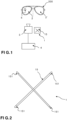
- Figure 1 shows a system according to one embodiment that enables to determine one or more features of one or two lenses 2, 2' mounted in a spectacle frame 200.
- Each lens 2, 2' is mounted in a corresponding lens receiving location of a spectacle frame 200.
- said one or more features that can be determined with the system includes geometrical parameter(s), optical parameter(s), and/or fitting parameter(s).
- Fitting parameter(s) can include the inter-pupillary distance or a pupil distance with reference to the optical or geometrical center of a lens or a pupil distance with regard to a reference part of the spectacle frame, such as the bottom of the spectacle frame.
- the fitting parameter(s) can also include an angle orientation of said lens or of both lenses, one with regard to the other, such as the wrap angle of the pantoscopic angle.
- Said one or more features can be one or more feature of the front face and/or the rear face of a lens.
- determining one or more features related to one lens or both lenses can also enable to determine one or more features of the spectacle frame itself, and for instance to determine one or more features of the corresponding receiving locations of the spectacle frame intended to receive the lenses.
- a non-point light pattern generating device 1 is configured for generating a predefined non-point light pattern 15.
- the non-point light pattern generating device 1 is arranged with regard to the spectacle frame 200 so that said predefined non-point light pattern 15 is reflected on lens 2. As a result, it is provided on said lens 2 a reflected non-point light pattern 5.
- the non-point light pattern generating device 1 has a non-point (non-directive) light source.
- the generated predefined non-point light pattern 15 can has one, two or three dimensions.
- the generated predefined non-point light pattern 15 has a predefined contour, predefined dimensions and predefined shape.
- non-point light pattern generating device 1 An example of a non-point light pattern generating device 1 is provided at Figure 2 .
- the predefined non-point light pattern 15 has a cross shape.
- the non-point light pattern generating device 1 can comprise neon tubes, for instance of 1,2 meters, arranged in a cross shape.
- the predefined non-point light pattern has a closed shape.
- the predefined non-point light pattern can have a closed round shape, such as a circle or an oval (i.e. ellipse).
- the predefined non-point light pattern is of the annular type, such as a circle rather than a disk, to have contrast between the skin of the head of the wearer and the reflected non-point light pattern.
- the predefined non-point light pattern 15 may have at least one extremity 151 or outer surface, in case of a closed shape, whose color differs from another part of the predefined non-point light pattern 15. Such color difference enables to reliably identify the extremity or outer surface of the reflected non-point light pattern on the lens.
- the extremity is of a color, for instance blue, that differs from the color of the main part of the luminous pattern.
- An image acquisition device 3 is configured for acquiring an image 5000 of the spectacle frame 200 provided with the two lenses 2, 2'.
- the image acquisition device 3 can be a digital camera that provides a digital image to a processing unit 4.
- the acquired image 5000 includes an image 5005 of the reflected non-point light pattern 5.
- the image 5005 of the reflected non-point light pattern 5 can include a part 5005A that corresponds to a reflection of the non-point light pattern on lens 2 and a part 5005B that corresponds to a reflection of the non-point light pattern on lens 2'.
- the images of the lenses 2, 2' that are included in acquired image 5005 are respectively referenced 5002 and 5002'.
- the contour of each lens 2, 2' determined by the system has also been superimposed on the image of the corresponding lens. Superimposed contours are referenced C5002 and C5002'.
- the image 5005 of the reflected non-point light pattern 5 can include a portion that is reflected on the front face of a lens and another portion that is reflected on the rear face. Discrimination and processing of these portions can be used to determine one or more features related to the corresponding faces of the lens.
- the non-point light pattern reflected by lens 2 and the non-point light pattern reflected by lens 2' can both derive from, or correspond to, said predefined non-point light pattern 15. It can be understood that although deriving from same source, the non-point light patterns reflected on the lenses can differ one from the other because of the differing features (for instance position, orientation, geometry, optical features) of the corresponding lens.
- a non-point light pattern reflected on the lenses can comprise, on the one hand, one element reflected by the lens corresponding to an element of the predefined non-point light pattern, and, on the other hand, another distinct element reflected by the other lens, that corresponds to another element of the predefined non-point light pattern.
- the distinct elements of the predefined non-point light pattern can provide from distinct sources.
- the processing unit 4 is configured for determining one or more features of the lens in function of one or more features of the reflected non-point light pattern 5.
- the processing unit 4 can include a processor (or controller) and a memory storing a computer program (computer instructions) adapted to be executed by the processor.
- processing unit 4 can include the contour and the shape of one or both faces of the lens. Other features can also be determined as explained below. According to embodiments the processing unit is configured for automatically digitizing the contour and/or the shape of at least one face of said at least one lens.
- the system can be included in a mobile device.
- the non-point light pattern generating device 1 can comprise a backlit display and the image acquisition device 3 can include a camera embedded in the mobile device.
- the mobile device can be a smartphone, a tablet, a laptop or similar, that includes a camera, a processor, a memory and a display screen.
- the system as disclosed above can be used to execute a method for determining one or more features of one or both lenses mounted in a spectacle frame.
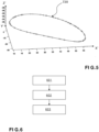
- a method according to one embodiment is illustrated at figure 6 .
- a predefined non-point light pattern 15 is generated.
- the predefined non-point light pattern 15 has a cross shape.
- the arrangement of the system and the spectacle frame makes said predefined non-point light pattern reflect on said at least one lens 2.
- a reflected non-point light pattern 5 appears on said at least one lens 2.
- an image 5000 of the spectacle frame 200 including an image 5005 of the reflected non-point light pattern 5, is acquired.
- the image can be memorized in a memory to be processed by the processing unit 4.
- the processing unit 4 analyzes one or more features of the image 5005 of the reflected non-point light pattern 5 and determines one or more features of one or both lenses mounted in a spectacle frame based on said analysis. Said analysis includes the comparison between features of the acquired image and features of the predefined non-point light pattern 15.
- the processing unit 4 can determine the distance between a lens and the image acquisition device. Determined distance can be used to reliably compare dimensions of the reflected non-point light pattern with the original predefined non-point light pattern to determine features of one or both lenses. In a variant, the distance can be a predefined value stored in a memory of the system.
- the distance is around one meter.
- the distance can be adapted so that a dimension (length or width) or size of the reflected non-point light pattern is larger than a corresponding dimension or size of the lens.
- the acquired image 5000 can be processed in a blue color channel. Indeed, the blue color provides better contrast with the human skin that reflects more red light.
- the processing unit determines, on the acquired image 5000, pixels where the reflected non-point light pattern 5 ends or has a discontinuity.
- the coordinates of determined pixels correspond to the contour of the lens 2.
- An example of such a digital 3D contour 720 of a lens that has been determined using the system, is illustrated at figure 5 with coordinates in a referential X', Y', Z' of points.
- Fourier descriptors that compute a discrete Fourier transform of a closed contour can be used to build the 3D contour digital file of the lens.
- points of the contour of a lens can be determined by moving the reflected non-point light pattern 5 on the lens as explained below.
- the system can be used to determine the shape and/or dimensions of lens 2.
- the processing unit 4 is configured for comparing the shape and/or dimensions of the image 5005 of the reflected non-point light pattern 5 with the shape and/or dimensions of the predefined non-point light pattern 15.
- the shape and/or dimensions of at least one face of said at least one lens 2 can then be determined in function of the result of the comparison.
- the processing unit 4 can be configured for determining relative position parameters of the two lenses of the spectacle frame 200 in function of one or more feature of the image 5005 of the reflected non-point light pattern.
- Said relative position parameters can include the wrap angle or the pantoscopic tilt of the lenses.
- the system includes a 3D optical head scanner.
- the 3D optical head scanner can be based on a passive technology such as a stereoscopic technology, and/or on an active technology that includes emission of light in the visible or invisible frequency field.
- the skilled man in the art can find information related to method and device using a 3D optical head scanner for instance in the article untitled "Device and method for precise repositioning of subjects for 3D Imaging of Head, Face, and Neck" by Richard C. Roth, Matthew DePauw and Andrew Hepner.
- Examples of 3D optical head scanner recommended for face digitalization include the system named faceSCAN III from company Breuckmann, and the system named Cyclops 2 from company InSpeck.
- the processing unit 4 is configured to control the 3D optical head scanner to execute a first scanning operation of the head of an individual that does not wear the spectacle frame 200 to obtain a first image, and a second scanning operation of the head of the individual that wears the spectacle frame 200 to obtain a second image.
- the processing unit can then compare one or more features of the first and second images, and determine at least one feature related to the position of at least one eye of the individual relatively to the corresponding lens 2, 2' of the spectacle frame 200 in function of the comparison.
- the system comprises a device that makes the reflected non-point light pattern 5 move relatively to the lens 2 so as to take a plurality of positions.
- the image acquisition device 3 acquire a sequence of images corresponding to said plurality of positions.
- the processing unit 4 can thus determine a feature such as the contour of the lens by analyzing the reflected non-point light patterns in the sequence of images.
- moving the reflected non-point light pattern 5 can be used to determine the edges of one or both lenses by identifying the positions where the reflected non-point light pattern 5 ends or is discontinuous. Determination of feature(s) related to the lens(es) can also include comparing the reflected non-point light patterns one with another, in the sequence of images.
- Such device used to make the reflected non-point light pattern 5 move can comprise a robot, for instance a multi-axis robot.
- the reflected non-point light pattern 5 can be moved on the corresponding lens by moving the generated non-point light pattern at various positions on an illuminating display screen used as the non-point light pattern generating device.
- lens 2 can be a neutral demonstration lens or an ophthalmic lens, also called correcting lens.
- the system can be used in an optical store to determine one or more features of a neutral lens 2 that is mounted on a spectacle frame that a customer has chosen. Indeed, once the spectacle frame is chosen, the operator has to get data related to the lenses of the spectacle frame to order ophthalmic lenses whose features are compatible not only with the ophthalmic corrections needed by the customer, but also with the features of the spectacle frame.
- the system can also be used with ophthalmic lenses mounted in the chosen spectacle frame to check that the machined ophthalmic lenses fit with the spectacle frame.
- the system enables to check that the lenses reliably fit the spectacle frame.
- the system enables to detect a difference between real measured data of a machined ophthalmic lens and target data that can be the result of a mechanical constraint during mounting of the machined ophthalmic lens in the spectacle frame.
- the lens can have measured geometrical features that differ from the target ones, because the lens curvature differs from the one of the corresponding location in the spectacle frame.
- the system enables to check that the curvature of the front and/or rear face of the machined ophthalmic lens corresponds to the target curvature. If needed, the throat of the corresponding location in the spectacle frame can be re-machined or a new lens with a more appropriate front and/or rear face can be ordered.
- the system can also be used with ophthalmic lenses mounted in a spectacle frame already worn by the customer to determine ophthalmic corrections of the ophthalmic lenses or retrieve other data of said lenses.
- the system can also be used to determine other lens or spectacle frame related data, such as one or more surface features of one or both lenses.
- Surface features can include:
- the system can also be used for verification of the positioning of the lens by locating the engraving that is used as a reference.
- the system enables locating engraving by identifying a break and/or discontinuity in the reflection, as it does for scratches. Once the engraving has been located, the system can check the correct centering of the corresponding lens mounted in a spectacle frame worn by the customer with regard to the corresponding pupil of the customer, independently of the mounting operation of the corresponding lens in the frame.
- the optician can remedy this by deforming the frame or adjusting nose pads.
- the mounting height and/or the mounting axis may not be correct, but the lens can however be correctly centered with regard to the corresponding pupil of the customer.
- acquisition is made in a configuration wherein the spectacle frame, with its lenses, is worn by an individual.
- the normal anatomical posture of the wearer's head corresponds to the position of the wearer's head in three dimensions for which Frankfurt's plane of the wearer's head lies in a horizontal plane.
- acquisition of the image can be done in a configuration wherein the spectacles are held on a support, but without being worn by the individual.
- Both configurations of acquisition can also be executed to compare the corresponding determined one or more features, since data, for instance the relative position or angle of the lenses, can differ from one configuration to the other.
- Measurement of the centering values for a wearer's spectacle frame can be impacted by the posture of the head and the position of the spectacle frame.
- a rotation of the wearer's head on the vertical axis in the primary viewing position has a direct effect on the pupillary distance values, and a bad position of the mount on the wearer's face can lead to a false measure of mounting height.
- a method is proposed below to improve the measurement of the pupillary distance, especially in the case of asymmetry between the right eye and the left eye, and the mounting height.
- This method makes it possible to reduce the errors of mounting height measurements that could result from a bad position of the spectacle frame on the wearer's head, and to manage differently the left and right asymmetries for the pupillary distance that could result from an asymmetry of the wearer's head, and to reduce the errors that could result from the wearer's position (headcap).
- a purpose of this method is to minimize the occurrence of false automatic measurements that could result from a bad wearer's position (posture) or a bad adjustment of the spectacle frame.
- the method is based on the automatic measurement of head tilt (headcap) and pupillary distances (or pupillary half-distances). Three cases can occur.
- the pupillary distance measurements are monocular pupillary distances (or pupillary half-distances).
- distance "EPOD” is the distance between the center of the right iris (or right pupil) and the center of the nose (or nasal bridge)
- distance "EPOG” is the distance between the center of the left iris (or left pupil) and the center of the nose (or nasal bridge).
- Second case If there is no rotation of the head in the primary viewing position (headcap equal to zero or lower than a threshold for example two degrees) and if there is symmetrical monocular pupillary distances (difference between distance "EPOD” and distance "EPOG” is equal to zero or inferior to a threshold for example 0.5 millimeter or 1 millimeter), then the measurement of pupillary distances is the binocular pupillary distance divided by 2.
- a method for determining the mounting height can be as follow with different cases.
- the above-described functions and steps may be implemented in the form of a computer program or via hardware components (e.g. programmable gate arrays).
- the functions and the steps performed by the processing unit, the image acquisition device and the non-point light pattern generating device may be performed or controlled by sets of computer instructions or modules implemented by a processor or a controller or they may be performed by dedicated electronic components of the field-programmable gate array (FPGA) or application-specific integrated circuit (ASIC) type. It is also possible to combine computer parts and electronic parts.
- FPGA field-programmable gate array
- ASIC application-specific integrated circuit
- the computer programs, or computer instructions may be contained in program storage devices, e.g. computer-readable digital data storage media, or executable programs.
- the programs or instructions may also be executed from program storage peripherals.
Landscapes
- Physics & Mathematics (AREA)
- Engineering & Computer Science (AREA)
- General Physics & Mathematics (AREA)
- Computer Vision & Pattern Recognition (AREA)
- Theoretical Computer Science (AREA)
- Optics & Photonics (AREA)
- Geometry (AREA)
- Health & Medical Sciences (AREA)
- Ophthalmology & Optometry (AREA)
- Eyeglasses (AREA)
Claims (14)
- System zum Bestimmen mindestens eines Merkmals von mindestens einem Brillenglas (2), montiert in einer Brillenfassung (200), wobei das System Folgendes umfasst:- eine Nicht-punkförmiges-Lichtmuster-Erzeugungsvorrichtung (1), ausgelegt zum Erzeugen eines vordefinierten nicht-punktförmigen Lichtmusters (15), und eingerichtet zum Reflektieren des vordefinierten nicht-punktförmigen Lichtmusters auf dem mindestens einen Brillenglas (2),- eine Bilderfassungsvorrichtung (3), ausgelegt zum Erfassen eines Bilds (5000) der Brillenfassung (200) einschließlich eines Bilds (5005) des reflektierten nicht-punktförmigen Lichtmusters (5), und- eine Verarbeitungseinheit (4),dadurch gekennzeichnet, dass die Verarbeitungseinheit (4) ausgelegt ist zum Bestimmen zumindest der Kontur des mindestens einen Brillenglases (2) als Funktion mindestens eines Merkmals des Bilds (5005) des reflektierten nicht-punktförmigen Lichtmusters (5), wobei die Verarbeitungseinheit (4) ausgelegt ist zum:- Vergleichen des Bilds (5005) des reflektierten nicht-punktförmigen Lichtmusters (5) mit dem vordefinierten nicht-punktförmigen Lichtmuster (15), um eine Unstetigkeit oder einen Riss in dem reflektierten nicht-punktförmigen Lichtmuster zu identifizieren; und- Bestimmen der Kontur des mindestens einen Brillenglases (2) durch Identifizieren des Orts der Unstetigkeit oder des Risses in dem reflektierten nicht-punktförmigen Lichtmuster.
- System nach Anspruch 1, wobei das mindestens eine Merkmal des mindestens einen Brillenglases (2) mindestens ein Parameter unter einer Gruppe von Parametern ist, die einen Geometrieparameter, einen optischen Parameter und einen Anpassparameter umfasst.
- System nach Anspruch 1 oder 2, wobei das vordefinierte nicht-punktförmige Lichtmuster (15) ein Kreuz ist.
- System nach einem der Ansprüche 1 oder 2, wobei das vordefinierte nicht-punktförmige Lichtmuster (15) eine geschlossene Gestalt aufweist.
- System nach einem der Ansprüche 1 bis 4, wobei das vordefinierte nicht-punktförmige Lichtmuster (15) mindestens eine Extremität (151) oder Außenfläche aufweist, deren Farbe sich von einem anderen Teil des vordefinierten nicht-punktförmigen Lichtmusters (15) unterscheidet.
- System nach einem der Ansprüche 1 bis 5, wobei die Verarbeitungseinheit (4) ausgelegt ist zum:- Vergleichen der Gestalt des Bilds (5005) des reflektierten nicht-punktförmigen Lichtmusters (5) mit der Gestalt des vordefinierten nicht-punktförmigen Lichtmusters (15),- Bestimmen der Gestalt von mindestens einer Fläche des mindestens einen Brillenglases (2) als Funktion des Ergebnisses des Vergleichs.
- System nach einem der Ansprüche 1 bis 6, wobei das nicht-punktförmige Lichtmuster von mindestens einem Brillenglas (2) und einem anderen Brillenglas (2') der Brillenfassung (200) reflektiert wird,
wobei die Verarbeitungseinheit (4) ausgelegt ist zum Bestimmen mindestens eines Relative-Position-Parameters der zwei Brillengläser (2, 2') als Funktion mindestens eines Merkmals des Bilds (5005) des reflektierten nicht-punktförmigen Lichtmusters. - System nach einem der Ansprüche 1 bis 7, wobei das System einen optischen 3D-Kopfscanner beinhaltet und die Verarbeitungseinheit (4) ausgelegt ist zum Steuern des optischen 3D-Kopfscanners zum Ausführen von:- einer ersten Scanoperation des Kopfes eines Individuums, das keine Brillenfassung (200) trägt, zum Erfassen eines ersten Bilds, und- einer zweiten Scanoperation des Kopfes des Individuums, das die Brillenfassung (200) trägt, zum Erfassen eines zweiten Bilds,und wobei die Verarbeitungseinheit (4) ausgelegt ist zum Bestimmen mindestens eines Merkmals, das die Position von mindestens einem Auge des Individuums relativ zu dem korrespondierenden Brillenglas (2, 2') der Brillenfassung (200) als Funktion des ersten und des zweiten Bilds betrifft.
- Mobilvorrichtung, die ein System nach einem der Ansprüche 1 bis 8 beinhaltet.
- Verfahren zum Bestimmen mindestens eines Merkmals von mindestens einem Brillenglas (2), montiert in einer Brillenfassung (200), wobei das Verfahren Folgendes umfasst:- Erzeugen eines vordefinierten nicht-punktförmigen Lichtmusters (15),- Zur-Reflexion-Bringen des vordefinierten nicht-punktförmigen Lichtmusters auf dem mindestens einen Brillenglas (2),- Erfassen eines Bilds (5000) der Brillenfassung (200) einschließlich eines Bilds (5005) des reflektierten nicht-punktförmigen Lichtmusters (5),- Bestimmen, mit einer Verarbeitungseinheit (4), mindestens eines Merkmals des mindestens einen Brillenglases (2) als Funktion mindestens eines Merkmals des Bilds (5005) des reflektierten nicht-punktförmigen Lichtmusters (5),dadurch gekennzeichnet, dass Bestimmen mindestens eines Merkmals des mindestens einen Brillenglases (2), Bestimmen der Kontur des mindestens einen Brillenglases (2) beinhaltet, die Verarbeitungseinheit (4) das Bild (5005) des reflektierten nicht-punktförmigen Lichtmusters (5) mit dem vordefinierten nicht-punktförmigen Lichtmuster (15) vergleicht, um eine Unstetigkeit oder einen Riss in dem reflektierten nicht-punktförmigen Lichtmuster zu identifizieren; und Bestimmen der Kontur des mindestens einen Brillenglases (2) durch Identifizieren des Orts der Unstetigkeit oder des Risses in dem reflektierten nicht-punktförmigen Lichtmuster.
- Verfahren nach Anspruch 10, wobei Bestimmen mindestens eines Merkmals des mindestens einen Brillenglases (2) Bestimmen der Gestalt des mindestens einen Brillenglases (2) beinhaltet.
- Verfahren nach einem der Ansprüche 10 bis 11, wobei das Verfahren in einer Ausgestaltung ausgeführt wird, in der die Brillenfassung (200) von einem Individuum getragen wird.
- Verfahren nach einem der Ansprüche 10 bis 12, wobei das Verfahren umfasst: Bewegen des nicht-punktförmigen Lichtmusters, das von dem mindestens einen Brillenglas reflektiert wird, gemäß einem vordefinierten Pfad relativ zu dem mindestens einen Brillenglas der Brillenfassung, so dass das reflektierte nicht-punktförmige Lichtmuster mit der Zeit eine Vielzahl von Positionen einnimmt, und Erfassen einer Vielzahl von dem Bild (5000) der Brillenfassung (200), einschließlich eines Bilds (5005) des reflektierten nicht-punktförmigen Lichtmusters (5), gemäß der Vielzahl von Positionen des reflektierten nicht-punktförmigen Lichtmusters.
- Nicht-transitorisches computerlesbares Trägermedium, das ein Programm speichert, zum Bewirken, dass das System nach Ansprüchen 1 bis 8 ein Verfahren ausführt, das Folgendes umfasst:- Steuern einer Nicht-punktförmiges-Lichtmuster-Erzeugungsvorrichtung (1) zum Erzeugen eines vordefinierten nicht-punktförmigen Lichtmusters (15), das von mindestens einem Brillenglas (2) reflektiert wird,- Steuern einer Bilderfassungsvorrichtung (3) zum Erfassen eines Bilds (5000) der Brillenfassung (200) einschließlich eines Bilds (5005) des reflektierten nicht-punktförmigen Lichtmusters (5),- Bestimmen, mit einer Verarbeitungseinheit (4), mindestens eines Merkmals des mindestens einen Brillenglases (2) als Funktion mindestens eines Merkmals des Bilds (5005) des reflektierten nicht-punktförmigen Lichtmusters (5), wobei Bestimmen mindestens eines Merkmals des mindestens einen Brillenglases (2) Bestimmen der Kontur des mindestens einen Brillenglases (2) beinhaltet, und wobei die Verarbeitungseinheit (4) das Bild (5005) des reflektierten nicht-punktförmigen Lichtmusters (5) mit dem vordefinierten nicht-punktförmigen Lichtmuster (15) vergleicht, um eine Unstetigkeit oder einen Riss in dem reflektierten nicht-punktförmigen Lichtmuster zu identifizieren; und Bestimmen der Kontur des mindestens einen Brillenglases (2) durch Identifizieren des Orts einer Unstetigkeit oder eines Risses in dem reflektierten nicht-punktförmigen Lichtmuster.
Applications Claiming Priority (2)
| Application Number | Priority Date | Filing Date | Title |
|---|---|---|---|
| EP19315073 | 2019-07-18 | ||
| PCT/EP2020/068596 WO2021008876A1 (en) | 2019-07-18 | 2020-07-02 | System and method for determining at least one feature of at least one lens mounted in a spectacle frame |
Publications (2)
| Publication Number | Publication Date |
|---|---|
| EP3999902A1 EP3999902A1 (de) | 2022-05-25 |
| EP3999902B1 true EP3999902B1 (de) | 2025-02-19 |
Family
ID=67587700
Family Applications (1)
| Application Number | Title | Priority Date | Filing Date |
|---|---|---|---|
| EP20736967.9A Active EP3999902B1 (de) | 2019-07-18 | 2020-07-02 | System und verfahren zum bestimmen wenistens eines merkmals wenigstens einer in einem brillengestell montierten linse |
Country Status (4)
| Country | Link |
|---|---|
| US (1) | US12044902B2 (de) |
| EP (1) | EP3999902B1 (de) |
| CN (1) | CN114127623B (de) |
| WO (1) | WO2021008876A1 (de) |
Families Citing this family (3)
| Publication number | Priority date | Publication date | Assignee | Title |
|---|---|---|---|---|
| US12345957B2 (en) * | 2020-01-10 | 2025-07-01 | Essilor International | Position variations of the lenses of an eyewear equipment |
| US12298598B2 (en) * | 2021-06-07 | 2025-05-13 | Blink Technologies Inc. | System and method for fitting eye wear |
| EP4194936A1 (de) * | 2021-12-10 | 2023-06-14 | Essilor International | Verfahren zur schätzung der position des optischen zentrums einer ophthalmischen linse |
Family Cites Families (17)
| Publication number | Priority date | Publication date | Assignee | Title |
|---|---|---|---|---|
| FR2910647B1 (fr) * | 2007-05-29 | 2009-11-27 | Essilor Int | Procede de detourage de lentilles ophtalmiques par lecture et mise a jour d'un registre de base de donnees de lentilles et/ou de montures |
| US20130088490A1 (en) * | 2011-04-04 | 2013-04-11 | Aaron Rasmussen | Method for eyewear fitting, recommendation, and customization using collision detection |
| EP3036701B1 (de) * | 2013-08-22 | 2026-03-04 | Bespoke, Inc. | Verfahren und system zur erzeugung von kundenspezifischen produkten |
| FR3016050B1 (fr) * | 2014-01-02 | 2017-12-08 | Essilor Int | Procede d’ajustage d’une monture de lunettes predeterminee pour son utilisation par un porteur donne |
| JP6701177B2 (ja) * | 2014-05-15 | 2020-05-27 | イーメージ ヴィジョン ピーティーイー. エルティーディー.Emage Vision Pte. Ltd. | 眼内レンズを検査するためのシステムおよび方法 |
| CN204188897U (zh) * | 2014-11-19 | 2015-03-04 | 温州市嘉光眼镜有限公司 | 防掉落静音眼镜 |
| US10330958B2 (en) * | 2015-04-10 | 2019-06-25 | Bespoke, Inc. | Systems and methods for creating eyewear with multi-focal lenses |
| WO2016176630A1 (en) * | 2015-04-30 | 2016-11-03 | Oakley, Inc. | Wearable devices such as eyewear customized to individual wearer parameters |
| EP3414515B1 (de) | 2016-02-12 | 2021-07-28 | Shamir Optical Industry Ltd. | Verfahren und systeme zum testen von brillengläsern |
| US10969301B2 (en) * | 2016-02-12 | 2021-04-06 | Shamir Optical Industry Ltd. | Self-administrated testing of eyeglasses |
| DE102016003512A1 (de) | 2016-03-22 | 2017-09-28 | Rodenstock Gmbh | Verfahren und Vorrichtung zur Ermittlung von 3D-Koordinaten zumindest eines vorbestimmten Punktes eines Objekts |
| WO2017205903A1 (en) * | 2016-06-01 | 2017-12-07 | Vidi Pty Ltd | An optical measuring and scanning system and methods of use |
| CA3037296A1 (en) * | 2016-09-19 | 2018-03-22 | Optimedica Corporation | Systems for opthalmic measurements and laser surgery and systems for surgical planning based thereon |
| EP3309603B1 (de) * | 2016-10-11 | 2019-01-02 | Essilor International | Verfahren zur bestimmung eines parameters einer optischen ausrüstung |
| US11036043B2 (en) * | 2019-01-17 | 2021-06-15 | Advanced New Technologies Co., Ltd. | Identity authentication using lens features |
| US11366343B2 (en) * | 2019-09-24 | 2022-06-21 | Bespoke, Inc. | Systems and methods for adjusting stock eyewear frames using a 3D scan of facial features |
| EP4083594B1 (de) * | 2019-12-26 | 2025-07-23 | Nidek Co., Ltd. | Brillenglasmessgerät und brillenglasmessprogramm |
-
2020
- 2020-07-02 EP EP20736967.9A patent/EP3999902B1/de active Active
- 2020-07-02 CN CN202080051919.7A patent/CN114127623B/zh active Active
- 2020-07-02 WO PCT/EP2020/068596 patent/WO2021008876A1/en not_active Ceased
- 2020-07-02 US US17/626,984 patent/US12044902B2/en active Active
Also Published As
| Publication number | Publication date |
|---|---|
| WO2021008876A1 (en) | 2021-01-21 |
| CN114127623A (zh) | 2022-03-01 |
| CN114127623B (zh) | 2024-08-09 |
| US12044902B2 (en) | 2024-07-23 |
| US20220252905A1 (en) | 2022-08-11 |
| EP3999902A1 (de) | 2022-05-25 |
Similar Documents
| Publication | Publication Date | Title |
|---|---|---|
| EP3339943B1 (de) | Verfahren und system zum erhalt optometrischer parameter zur anpassung von brillengläsern | |
| US10890784B2 (en) | Methods, devices, and computer program for determining a near-vision point | |
| US10216010B2 (en) | Determining user data based on image data of a selected eyeglass frame | |
| JP2019194702A (ja) | 累進眼科用レンズの少なくとも1つの光学的設計パラメータを判断する方法 | |
| EP3999902B1 (de) | System und verfahren zum bestimmen wenistens eines merkmals wenigstens einer in einem brillengestell montierten linse | |
| CN111031893A (zh) | 用于确定与眼科装置相关联的至少一个参数的方法 | |
| IL264747B1 (en) | Method and device for checking the focus of at least one eyeglass lens | |
| US11397339B2 (en) | Computer-implemented method for determining centring parameters | |
| JP2003329541A (ja) | アイポイントの位置決定方法及びアイポイント測定システム | |
| US11747654B2 (en) | Computer-implemented method for generating data in order to produce at least one spectacle lens, and method for producing a pair of spectacles | |
| CN109416477B (zh) | 用于检测与配戴者和/或与配戴者选择的镜架相关的数据集中的可能差错的方法 | |
| US20160327450A1 (en) | Lens inspection device and method of manufacturing spectacle lens | |
| CA3066526A1 (en) | Method and system for determining a pupillary distance of an individual | |
| US10960511B2 (en) | Method of trimming optical lenses | |
| KR20190099313A (ko) | 안경 렌즈를 설계하는 방법, 렌즈 및 렌즈를 설계하기 위한 장치 | |
| CN111417893B (zh) | 用于检验眼科镜片在镜架中的安装的方法和组件 | |
| EP4455769A1 (de) | Verfahren und vorrichtung zum zentrieren einer ophthalmischen linse | |
| IL286236B1 (en) | Method, centering device and computer program product for measuring the distance of a user from a centering device | |
| US11624939B2 (en) | Automatic establishment of parameters necessary for constructing spectacles | |
| CN110785114B (zh) | 高精确地确定眼睛的瞳孔直径的方法和与此相关的设备 | |
| KR102299051B1 (ko) | 안경렌즈 처방을 위한 3차원 매개변수 측정 장치 및 방법 | |
| CN119487439A (zh) | 眼镜镜片的虚拟表示数据集以及用于生成其的方法和装置 |
Legal Events
| Date | Code | Title | Description |
|---|---|---|---|
| STAA | Information on the status of an ep patent application or granted ep patent |
Free format text: STATUS: UNKNOWN |
|
| STAA | Information on the status of an ep patent application or granted ep patent |
Free format text: STATUS: THE INTERNATIONAL PUBLICATION HAS BEEN MADE |
|
| PUAI | Public reference made under article 153(3) epc to a published international application that has entered the european phase |
Free format text: ORIGINAL CODE: 0009012 |
|
| STAA | Information on the status of an ep patent application or granted ep patent |
Free format text: STATUS: REQUEST FOR EXAMINATION WAS MADE |
|
| 17P | Request for examination filed |
Effective date: 20220117 |
|
| AK | Designated contracting states |
Kind code of ref document: A1 Designated state(s): AL AT BE BG CH CY CZ DE DK EE ES FI FR GB GR HR HU IE IS IT LI LT LU LV MC MK MT NL NO PL PT RO RS SE SI SK SM TR |
|
| DAV | Request for validation of the european patent (deleted) | ||
| DAX | Request for extension of the european patent (deleted) | ||
| P01 | Opt-out of the competence of the unified patent court (upc) registered |
Effective date: 20230525 |
|
| GRAP | Despatch of communication of intention to grant a patent |
Free format text: ORIGINAL CODE: EPIDOSNIGR1 |
|
| STAA | Information on the status of an ep patent application or granted ep patent |
Free format text: STATUS: GRANT OF PATENT IS INTENDED |
|
| INTG | Intention to grant announced |
Effective date: 20240611 |
|
| GRAJ | Information related to disapproval of communication of intention to grant by the applicant or resumption of examination proceedings by the epo deleted |
Free format text: ORIGINAL CODE: EPIDOSDIGR1 |
|
| STAA | Information on the status of an ep patent application or granted ep patent |
Free format text: STATUS: REQUEST FOR EXAMINATION WAS MADE |
|
| INTC | Intention to grant announced (deleted) | ||
| GRAP | Despatch of communication of intention to grant a patent |
Free format text: ORIGINAL CODE: EPIDOSNIGR1 |
|
| STAA | Information on the status of an ep patent application or granted ep patent |
Free format text: STATUS: GRANT OF PATENT IS INTENDED |
|
| INTG | Intention to grant announced |
Effective date: 20240906 |
|
| GRAF | Information related to payment of grant fee modified |
Free format text: ORIGINAL CODE: EPIDOSCIGR3 |
|
| GRAS | Grant fee paid |
Free format text: ORIGINAL CODE: EPIDOSNIGR3 |
|
| GRAA | (expected) grant |
Free format text: ORIGINAL CODE: 0009210 |
|
| STAA | Information on the status of an ep patent application or granted ep patent |
Free format text: STATUS: THE PATENT HAS BEEN GRANTED |
|
| AK | Designated contracting states |
Kind code of ref document: B1 Designated state(s): AL AT BE BG CH CY CZ DE DK EE ES FI FR GB GR HR HU IE IS IT LI LT LU LV MC MK MT NL NO PL PT RO RS SE SI SK SM TR |
|
| REG | Reference to a national code |
Ref country code: GB Ref legal event code: FG4D |
|
| REG | Reference to a national code |
Ref country code: CH Ref legal event code: EP |
|
| REG | Reference to a national code |
Ref country code: IE Ref legal event code: FG4D |
|
| REG | Reference to a national code |
Ref country code: DE Ref legal event code: R096 Ref document number: 602020046311 Country of ref document: DE |
|
| REG | Reference to a national code |
Ref country code: NL Ref legal event code: MP Effective date: 20250219 |
|
| PG25 | Lapsed in a contracting state [announced via postgrant information from national office to epo] |
Ref country code: RS Free format text: LAPSE BECAUSE OF FAILURE TO SUBMIT A TRANSLATION OF THE DESCRIPTION OR TO PAY THE FEE WITHIN THE PRESCRIBED TIME-LIMIT Effective date: 20250519 |
|
| PG25 | Lapsed in a contracting state [announced via postgrant information from national office to epo] |
Ref country code: FI Free format text: LAPSE BECAUSE OF FAILURE TO SUBMIT A TRANSLATION OF THE DESCRIPTION OR TO PAY THE FEE WITHIN THE PRESCRIBED TIME-LIMIT Effective date: 20250219 |
|
| PG25 | Lapsed in a contracting state [announced via postgrant information from national office to epo] |
Ref country code: PL Free format text: LAPSE BECAUSE OF FAILURE TO SUBMIT A TRANSLATION OF THE DESCRIPTION OR TO PAY THE FEE WITHIN THE PRESCRIBED TIME-LIMIT Effective date: 20250219 |
|
| PG25 | Lapsed in a contracting state [announced via postgrant information from national office to epo] |
Ref country code: ES Free format text: LAPSE BECAUSE OF FAILURE TO SUBMIT A TRANSLATION OF THE DESCRIPTION OR TO PAY THE FEE WITHIN THE PRESCRIBED TIME-LIMIT Effective date: 20250219 |
|
| REG | Reference to a national code |
Ref country code: LT Ref legal event code: MG9D |
|
| PG25 | Lapsed in a contracting state [announced via postgrant information from national office to epo] |
Ref country code: IS Free format text: LAPSE BECAUSE OF FAILURE TO SUBMIT A TRANSLATION OF THE DESCRIPTION OR TO PAY THE FEE WITHIN THE PRESCRIBED TIME-LIMIT Effective date: 20250619 Ref country code: NO Free format text: LAPSE BECAUSE OF FAILURE TO SUBMIT A TRANSLATION OF THE DESCRIPTION OR TO PAY THE FEE WITHIN THE PRESCRIBED TIME-LIMIT Effective date: 20250519 |
|
| PG25 | Lapsed in a contracting state [announced via postgrant information from national office to epo] |
Ref country code: NL Free format text: LAPSE BECAUSE OF FAILURE TO SUBMIT A TRANSLATION OF THE DESCRIPTION OR TO PAY THE FEE WITHIN THE PRESCRIBED TIME-LIMIT Effective date: 20250219 |
|
| PG25 | Lapsed in a contracting state [announced via postgrant information from national office to epo] |
Ref country code: HR Free format text: LAPSE BECAUSE OF FAILURE TO SUBMIT A TRANSLATION OF THE DESCRIPTION OR TO PAY THE FEE WITHIN THE PRESCRIBED TIME-LIMIT Effective date: 20250219 |
|
| PG25 | Lapsed in a contracting state [announced via postgrant information from national office to epo] |
Ref country code: PT Free format text: LAPSE BECAUSE OF FAILURE TO SUBMIT A TRANSLATION OF THE DESCRIPTION OR TO PAY THE FEE WITHIN THE PRESCRIBED TIME-LIMIT Effective date: 20250620 Ref country code: LV Free format text: LAPSE BECAUSE OF FAILURE TO SUBMIT A TRANSLATION OF THE DESCRIPTION OR TO PAY THE FEE WITHIN THE PRESCRIBED TIME-LIMIT Effective date: 20250219 |
|
| PG25 | Lapsed in a contracting state [announced via postgrant information from national office to epo] |
Ref country code: GR Free format text: LAPSE BECAUSE OF FAILURE TO SUBMIT A TRANSLATION OF THE DESCRIPTION OR TO PAY THE FEE WITHIN THE PRESCRIBED TIME-LIMIT Effective date: 20250520 Ref country code: BG Free format text: LAPSE BECAUSE OF FAILURE TO SUBMIT A TRANSLATION OF THE DESCRIPTION OR TO PAY THE FEE WITHIN THE PRESCRIBED TIME-LIMIT Effective date: 20250219 |
|
| REG | Reference to a national code |
Ref country code: AT Ref legal event code: MK05 Ref document number: 1768822 Country of ref document: AT Kind code of ref document: T Effective date: 20250219 |
|
| PG25 | Lapsed in a contracting state [announced via postgrant information from national office to epo] |
Ref country code: SE Free format text: LAPSE BECAUSE OF FAILURE TO SUBMIT A TRANSLATION OF THE DESCRIPTION OR TO PAY THE FEE WITHIN THE PRESCRIBED TIME-LIMIT Effective date: 20250219 |
|
| PG25 | Lapsed in a contracting state [announced via postgrant information from national office to epo] |
Ref country code: SM Free format text: LAPSE BECAUSE OF FAILURE TO SUBMIT A TRANSLATION OF THE DESCRIPTION OR TO PAY THE FEE WITHIN THE PRESCRIBED TIME-LIMIT Effective date: 20250219 |
|
| PG25 | Lapsed in a contracting state [announced via postgrant information from national office to epo] |
Ref country code: DK Free format text: LAPSE BECAUSE OF FAILURE TO SUBMIT A TRANSLATION OF THE DESCRIPTION OR TO PAY THE FEE WITHIN THE PRESCRIBED TIME-LIMIT Effective date: 20250219 |
|
| PGFP | Annual fee paid to national office [announced via postgrant information from national office to epo] |
Ref country code: DE Payment date: 20250729 Year of fee payment: 6 |
|
| PGFP | Annual fee paid to national office [announced via postgrant information from national office to epo] |
Ref country code: IT Payment date: 20250721 Year of fee payment: 6 |
|
| PGFP | Annual fee paid to national office [announced via postgrant information from national office to epo] |
Ref country code: GB Payment date: 20250728 Year of fee payment: 6 |
|
| PG25 | Lapsed in a contracting state [announced via postgrant information from national office to epo] |
Ref country code: AT Free format text: LAPSE BECAUSE OF FAILURE TO SUBMIT A TRANSLATION OF THE DESCRIPTION OR TO PAY THE FEE WITHIN THE PRESCRIBED TIME-LIMIT Effective date: 20250219 |
|
| PGFP | Annual fee paid to national office [announced via postgrant information from national office to epo] |
Ref country code: FR Payment date: 20250725 Year of fee payment: 6 |
|
| PG25 | Lapsed in a contracting state [announced via postgrant information from national office to epo] |
Ref country code: EE Free format text: LAPSE BECAUSE OF FAILURE TO SUBMIT A TRANSLATION OF THE DESCRIPTION OR TO PAY THE FEE WITHIN THE PRESCRIBED TIME-LIMIT Effective date: 20250219 Ref country code: CZ Free format text: LAPSE BECAUSE OF FAILURE TO SUBMIT A TRANSLATION OF THE DESCRIPTION OR TO PAY THE FEE WITHIN THE PRESCRIBED TIME-LIMIT Effective date: 20250219 |
|
| PG25 | Lapsed in a contracting state [announced via postgrant information from national office to epo] |
Ref country code: RO Free format text: LAPSE BECAUSE OF FAILURE TO SUBMIT A TRANSLATION OF THE DESCRIPTION OR TO PAY THE FEE WITHIN THE PRESCRIBED TIME-LIMIT Effective date: 20250219 |
|
| PG25 | Lapsed in a contracting state [announced via postgrant information from national office to epo] |
Ref country code: SK Free format text: LAPSE BECAUSE OF FAILURE TO SUBMIT A TRANSLATION OF THE DESCRIPTION OR TO PAY THE FEE WITHIN THE PRESCRIBED TIME-LIMIT Effective date: 20250219 |
|
| REG | Reference to a national code |
Ref country code: DE Ref legal event code: R097 Ref document number: 602020046311 Country of ref document: DE |
|
| PLBE | No opposition filed within time limit |
Free format text: ORIGINAL CODE: 0009261 |
|
| STAA | Information on the status of an ep patent application or granted ep patent |
Free format text: STATUS: NO OPPOSITION FILED WITHIN TIME LIMIT |
|
| REG | Reference to a national code |
Ref country code: CH Ref legal event code: L10 Free format text: ST27 STATUS EVENT CODE: U-0-0-L10-L00 (AS PROVIDED BY THE NATIONAL OFFICE) Effective date: 20251231 |
|
| 26N | No opposition filed |
Effective date: 20251120 |
|
| REG | Reference to a national code |
Ref country code: CH Ref legal event code: H13 Free format text: ST27 STATUS EVENT CODE: U-0-0-H10-H13 (AS PROVIDED BY THE NATIONAL OFFICE) Effective date: 20260224 |
|
| PG25 | Lapsed in a contracting state [announced via postgrant information from national office to epo] |
Ref country code: LU Free format text: LAPSE BECAUSE OF NON-PAYMENT OF DUE FEES Effective date: 20250702 |