EP3998435A1 - Cooling system - Google Patents
Cooling system Download PDFInfo
- Publication number
- EP3998435A1 EP3998435A1 EP19937218.6A EP19937218A EP3998435A1 EP 3998435 A1 EP3998435 A1 EP 3998435A1 EP 19937218 A EP19937218 A EP 19937218A EP 3998435 A1 EP3998435 A1 EP 3998435A1
- Authority
- EP
- European Patent Office
- Prior art keywords
- refrigerant
- pressure
- cooling system
- turbo compressor
- heat
- Prior art date
- Legal status (The legal status is an assumption and is not a legal conclusion. Google has not performed a legal analysis and makes no representation as to the accuracy of the status listed.)
- Withdrawn
Links
Images

Classifications
-
- F—MECHANICAL ENGINEERING; LIGHTING; HEATING; WEAPONS; BLASTING
- F25—REFRIGERATION OR COOLING; COMBINED HEATING AND REFRIGERATION SYSTEMS; HEAT PUMP SYSTEMS; MANUFACTURE OR STORAGE OF ICE; LIQUEFACTION SOLIDIFICATION OF GASES
- F25B—REFRIGERATION MACHINES, PLANTS OR SYSTEMS; COMBINED HEATING AND REFRIGERATION SYSTEMS; HEAT PUMP SYSTEMS
- F25B1/00—Compression machines, plants or systems with non-reversible cycle
- F25B1/04—Compression machines, plants or systems with non-reversible cycle with compressor of rotary type
- F25B1/053—Compression machines, plants or systems with non-reversible cycle with compressor of rotary type of turbine type
-
- H—ELECTRICITY
- H05—ELECTRIC TECHNIQUES NOT OTHERWISE PROVIDED FOR
- H05K—PRINTED CIRCUITS; CASINGS OR CONSTRUCTIONAL DETAILS OF ELECTRIC APPARATUS; MANUFACTURE OF ASSEMBLAGES OF ELECTRICAL COMPONENTS
- H05K7/00—Constructional details common to different types of electric apparatus
- H05K7/20—Modifications to facilitate cooling, ventilating, or heating
- H05K7/2029—Modifications to facilitate cooling, ventilating, or heating using a liquid coolant with phase change in electronic enclosures
- H05K7/20327—Accessories for moving fluid, for connecting fluid conduits, for distributing fluid or for preventing leakage, e.g. pumps, tanks or manifolds
-
- F—MECHANICAL ENGINEERING; LIGHTING; HEATING; WEAPONS; BLASTING
- F25—REFRIGERATION OR COOLING; COMBINED HEATING AND REFRIGERATION SYSTEMS; HEAT PUMP SYSTEMS; MANUFACTURE OR STORAGE OF ICE; LIQUEFACTION SOLIDIFICATION OF GASES
- F25B—REFRIGERATION MACHINES, PLANTS OR SYSTEMS; COMBINED HEATING AND REFRIGERATION SYSTEMS; HEAT PUMP SYSTEMS
- F25B49/00—Arrangement or mounting of control or safety devices
- F25B49/005—Arrangement or mounting of control or safety devices of safety devices
-
- F—MECHANICAL ENGINEERING; LIGHTING; HEATING; WEAPONS; BLASTING
- F25—REFRIGERATION OR COOLING; COMBINED HEATING AND REFRIGERATION SYSTEMS; HEAT PUMP SYSTEMS; MANUFACTURE OR STORAGE OF ICE; LIQUEFACTION SOLIDIFICATION OF GASES
- F25B—REFRIGERATION MACHINES, PLANTS OR SYSTEMS; COMBINED HEATING AND REFRIGERATION SYSTEMS; HEAT PUMP SYSTEMS
- F25B49/00—Arrangement or mounting of control or safety devices
- F25B49/02—Arrangement or mounting of control or safety devices for compression type machines, plants or systems
-
- H—ELECTRICITY
- H05—ELECTRIC TECHNIQUES NOT OTHERWISE PROVIDED FOR
- H05K—PRINTED CIRCUITS; CASINGS OR CONSTRUCTIONAL DETAILS OF ELECTRIC APPARATUS; MANUFACTURE OF ASSEMBLAGES OF ELECTRICAL COMPONENTS
- H05K7/00—Constructional details common to different types of electric apparatus
- H05K7/20—Modifications to facilitate cooling, ventilating, or heating
- H05K7/2029—Modifications to facilitate cooling, ventilating, or heating using a liquid coolant with phase change in electronic enclosures
- H05K7/20309—Evaporators
-
- H—ELECTRICITY
- H05—ELECTRIC TECHNIQUES NOT OTHERWISE PROVIDED FOR
- H05K—PRINTED CIRCUITS; CASINGS OR CONSTRUCTIONAL DETAILS OF ELECTRIC APPARATUS; MANUFACTURE OF ASSEMBLAGES OF ELECTRICAL COMPONENTS
- H05K7/00—Constructional details common to different types of electric apparatus
- H05K7/20—Modifications to facilitate cooling, ventilating, or heating
- H05K7/2029—Modifications to facilitate cooling, ventilating, or heating using a liquid coolant with phase change in electronic enclosures
- H05K7/20318—Condensers
-
- H—ELECTRICITY
- H05—ELECTRIC TECHNIQUES NOT OTHERWISE PROVIDED FOR
- H05K—PRINTED CIRCUITS; CASINGS OR CONSTRUCTIONAL DETAILS OF ELECTRIC APPARATUS; MANUFACTURE OF ASSEMBLAGES OF ELECTRICAL COMPONENTS
- H05K7/00—Constructional details common to different types of electric apparatus
- H05K7/20—Modifications to facilitate cooling, ventilating, or heating
- H05K7/20709—Modifications to facilitate cooling, ventilating, or heating for server racks or cabinets; for data centers, e.g. 19-inch computer racks
- H05K7/208—Liquid cooling with phase change
- H05K7/20827—Liquid cooling with phase change within rooms for removing heat from cabinets, e.g. air conditioning devices
-
- F—MECHANICAL ENGINEERING; LIGHTING; HEATING; WEAPONS; BLASTING
- F25—REFRIGERATION OR COOLING; COMBINED HEATING AND REFRIGERATION SYSTEMS; HEAT PUMP SYSTEMS; MANUFACTURE OR STORAGE OF ICE; LIQUEFACTION SOLIDIFICATION OF GASES
- F25B—REFRIGERATION MACHINES, PLANTS OR SYSTEMS; COMBINED HEATING AND REFRIGERATION SYSTEMS; HEAT PUMP SYSTEMS
- F25B2400/00—Component parts or details not otherwise provided for in this subclass
- F25B2400/04—Refrigeration circuit bypassing means
- F25B2400/0401—Refrigeration circuit bypassing means for compressors
-
- F—MECHANICAL ENGINEERING; LIGHTING; HEATING; WEAPONS; BLASTING
- F25—REFRIGERATION OR COOLING; COMBINED HEATING AND REFRIGERATION SYSTEMS; HEAT PUMP SYSTEMS; MANUFACTURE OR STORAGE OF ICE; LIQUEFACTION SOLIDIFICATION OF GASES
- F25B—REFRIGERATION MACHINES, PLANTS OR SYSTEMS; COMBINED HEATING AND REFRIGERATION SYSTEMS; HEAT PUMP SYSTEMS
- F25B2500/00—Problems to be solved
- F25B2500/07—Exceeding a certain pressure value in a refrigeration component or cycle
-
- F—MECHANICAL ENGINEERING; LIGHTING; HEATING; WEAPONS; BLASTING
- F25—REFRIGERATION OR COOLING; COMBINED HEATING AND REFRIGERATION SYSTEMS; HEAT PUMP SYSTEMS; MANUFACTURE OR STORAGE OF ICE; LIQUEFACTION SOLIDIFICATION OF GASES
- F25B—REFRIGERATION MACHINES, PLANTS OR SYSTEMS; COMBINED HEATING AND REFRIGERATION SYSTEMS; HEAT PUMP SYSTEMS
- F25B2600/00—Control issues
- F25B2600/02—Compressor control
- F25B2600/025—Compressor control by controlling speed
- F25B2600/0253—Compressor control by controlling speed with variable speed
-
- F—MECHANICAL ENGINEERING; LIGHTING; HEATING; WEAPONS; BLASTING
- F25—REFRIGERATION OR COOLING; COMBINED HEATING AND REFRIGERATION SYSTEMS; HEAT PUMP SYSTEMS; MANUFACTURE OR STORAGE OF ICE; LIQUEFACTION SOLIDIFICATION OF GASES
- F25B—REFRIGERATION MACHINES, PLANTS OR SYSTEMS; COMBINED HEATING AND REFRIGERATION SYSTEMS; HEAT PUMP SYSTEMS
- F25B2600/00—Control issues
- F25B2600/25—Control of valves
- F25B2600/2501—Bypass valves
-
- F—MECHANICAL ENGINEERING; LIGHTING; HEATING; WEAPONS; BLASTING
- F25—REFRIGERATION OR COOLING; COMBINED HEATING AND REFRIGERATION SYSTEMS; HEAT PUMP SYSTEMS; MANUFACTURE OR STORAGE OF ICE; LIQUEFACTION SOLIDIFICATION OF GASES
- F25B—REFRIGERATION MACHINES, PLANTS OR SYSTEMS; COMBINED HEATING AND REFRIGERATION SYSTEMS; HEAT PUMP SYSTEMS
- F25B2700/00—Sensing or detecting of parameters; Sensors therefor
- F25B2700/19—Pressures
- F25B2700/193—Pressures of the compressor
- F25B2700/1931—Discharge pressures
-
- F—MECHANICAL ENGINEERING; LIGHTING; HEATING; WEAPONS; BLASTING
- F25—REFRIGERATION OR COOLING; COMBINED HEATING AND REFRIGERATION SYSTEMS; HEAT PUMP SYSTEMS; MANUFACTURE OR STORAGE OF ICE; LIQUEFACTION SOLIDIFICATION OF GASES
- F25B—REFRIGERATION MACHINES, PLANTS OR SYSTEMS; COMBINED HEATING AND REFRIGERATION SYSTEMS; HEAT PUMP SYSTEMS
- F25B2700/00—Sensing or detecting of parameters; Sensors therefor
- F25B2700/19—Pressures
- F25B2700/193—Pressures of the compressor
- F25B2700/1933—Suction pressures
-
- F—MECHANICAL ENGINEERING; LIGHTING; HEATING; WEAPONS; BLASTING
- F25—REFRIGERATION OR COOLING; COMBINED HEATING AND REFRIGERATION SYSTEMS; HEAT PUMP SYSTEMS; MANUFACTURE OR STORAGE OF ICE; LIQUEFACTION SOLIDIFICATION OF GASES
- F25B—REFRIGERATION MACHINES, PLANTS OR SYSTEMS; COMBINED HEATING AND REFRIGERATION SYSTEMS; HEAT PUMP SYSTEMS
- F25B5/00—Compression machines, plants or systems, with several evaporator circuits, e.g. for varying refrigerating capacity
- F25B5/02—Compression machines, plants or systems, with several evaporator circuits, e.g. for varying refrigerating capacity arranged in parallel
Definitions
- the present invention relates to a cooling system for efficiently exhausting heat from an electronic device that serves as a heat source.
- a heat exchange system that exhausts heat generated by the electronic devices by adopting a cooling system that achieves heat transfer due to the phase changes of evaporation and condensation of a refrigerant even if a large amount of heat is generated during high-load operation of the electronic devices.
- the cooling system shown in Patent Document 1 includes an equipment room in which a plurality of electronic devices are arranged, an evaporator provided near these electronic devices to cool the electronic devices by vaporizing a refrigerant, a cooling tower that cools and condenses the vaporized refrigerant by means of the outside air, a compressor for compressing the vaporized refrigerant, and a circulation line connected so that the refrigerant circulates between the evaporator, the compressor and the cooling tower.
- thermosiphon heat exchanger on the user side
- the refrigerant used in the thermosiphon is a refrigerant having a lower pressure and a lower risk than the refrigerant used in the refrigeration cycle.
- Patent Documents 1 and 2 describe a constitution relating to a heat exchange system that exhausts heat by utilizing the phase change cycle of evaporation/condensation of a refrigerant.
- the present invention has been made in view of the above circumstances, and provides a cooling system capable of comprehensively improving the efficiency of the evaporation/condensation phase-change cycle of a refrigerant.
- the present invention proposes the following means.
- a cooling system of the present invention includes a local cooler that is positioned near a heat source and that evaporates a liquid-phase refrigerant by receiving heat from the heat source, a turbo compressor that compresses a gas-phase refrigerant produced in the local cooler, an outdoor unit that condenses the gas-phase refrigerant supplied from the turbo compressor by heat dissipation, and an expansion valve that depressurizes the refrigerant supplied from the outdoor unit and sends the refrigerant to the local cooler, the refrigerant being a low-pressure refrigerant having a condensing pressure lower than a prescribed value.
- the cooling system of the present invention enables efficient operation in evaporation, condensation and handling of a refrigerant.
- a cooling system 10 according to the present invention will be described with reference to FIG. 1 .
- the cooling system 10 mainly includes a local cooler 1, a turbo compressor 2, an outdoor unit 3, and an expansion valve 4.
- the local cooler 1 has a heat exchange unit 5 that is positioned near servers S that serves as heat sources in a server room (upper position of an exhaust area E positioned between the servers S in the figure) to directly receive heat from the server S.
- the heat exchange unit 5 of the local cooler 1 exhausts heat from the servers S by evaporating an internal liquid-phase refrigerant with the heat of the servers S.
- the turbo compressor 2 is for compressing the gas-phase refrigerant produced in the local cooler 1 and forcibly sending the refrigerant to the outdoor unit 3.
- a centrifugal compressor in which a plurality of impellers are arranged around a rotating shaft is used.
- the outdoor unit 3 is for condensing the gas-phase refrigerant by performing heat dissipation to an external space on the gas-phase refrigerant supplied from the turbo compressor 2.
- the expansion valve 4 is for depressurizing the refrigerant supplied from the outdoor unit 3 to obtain a complete liquid-phase refrigerant, and afterward sending the refrigerant to the local cooler 1.
- a low-pressure refrigerant having a condensing pressure lower than a predetermined value is used.
- a low-pressure refrigerant with lower condensing pressure than conventional air conditioning refrigerants subject to the High Pressure Gas Safety Act that is, a low-pressure refrigerant with a high cycle rate not subject to the High Pressure Gas Safety Act, easy to deliver in parts, and not requiring a person qualified in relation to high-pressure gas. Therefore, there is an advantage that it is not necessary to go through troublesome procedures such as equipment inspection each time even if additional work is required, such as when adding the cooling system 10 with the addition of a server as a heat source.
- turbo compressor which is superior to a positive displacement compressor in the amount of refrigerant transported per volume (total amount of calorific value to be transported).
- the cooling system 10 uses a low-pressure refrigerant with low condensing pressure as the refrigerant, and uses the turbo compressor 2 as a compressor that compresses the refrigerant evaporated by the local cooler 1, whereby highly efficient refrigerant compression is possible, and as a result it becomes possible to efficiently exhaust heat from the electronic device in the server S that serves as the heat source.
- refrigerant a low-pressure refrigerant that is not subject to the High Pressure Gas Safety Act, is easy to deliver in parts, and does not require a person qualified in relation to high-pressure gas in the cooling system 10 of the present invention, efficient refrigerant handling is possible, and operational efficiency can be improved in this respect as well.
- the local cooler 1 positioned near the heat source can directly receive the heat from the electronic device in the server S serving as the heat source to evaporate the liquid-phase refrigerant, efficient heat transfer from the heat source and refrigerant evaporation are possible.
- the cooling system 10 of the present invention enables efficient operation in all of the evaporation, condensation, and handling of the refrigerant.
- FIG. 2 A system diagram of the cooling system 101 according to the first example embodiment of the present invention will be described with reference to FIG. 2 .
- the cooling system 101 mainly includes local coolers 310 and 320, a turbo compressor 410, an outdoor unit 500, and an expansion valve 420.
- the local coolers 310 and 320, the turbo compressor 410 and the outdoor unit 500 are connected by vapor pipes 610 and 620, while the outdoor unit 500, the expansion valve 420 and the local coolers 310 and 320 are connected by liquid pipes 630 and 640.
- components other than the outdoor unit 500 are arranged in the server room 100.
- the turbo compressor 410 and the expansion valve 420 in the server room 100 are installed in an indoor unit 400.
- the local coolers 310 and 320 are arranged near servers S1, which are heat sources in the server room, and include heat exchange units 310A and 320A which directly receive the heat from the servers S1.
- a plurality of the servers S 1 are housed in server racks 201 to 204 arranged at regular intervals, and the heat is discharged toward an exhaust area E1 located between the server racks 201 and 204.
- the heat exchange units 310A and 320A of the local coolers 310 and 320 are located above the exhaust area E1 between the server racks 201 and 204, and by evaporating the internal liquid-phase refrigerant with the heat of the servers S1, exhaust the heat from the exhaust area E1.
- the turbo compressor 410 is for compressing the gas-phase refrigerant generated in the local coolers 310 and 320 and forcibly sending the gas-phase refrigerant to the outdoor unit 500.
- a centrifugal compressor in which a plurality of impellers are arranged around a rotating shaft is used as the turbo compressor 410, and by compressing and pressurizing the gas-phase refrigerant taken in from the suction nozzle with the centrifugal force when passing through high-speed rotating impellers, the gas-phase refrigerant is discharged from the exhaust nozzle.
- the outdoor unit 500 is for condensing the gas-phase refrigerant by dissipating heat of the gas-phase refrigerant supplied from the turbo compressor 410 to the external space.
- the expansion valve 420 is for depressurizing the refrigerant supplied from the outdoor unit 500 to obtain a complete liquid-phase refrigerant and then sending the liquid-phase refrigerant to the local coolers 310 and 320.
- the refrigerant evaporates in the heat exchange units 310A and 320A of the local coolers 310 and 320 individually installed above the exhaust areas E1 of the server racks 201 to 204, whereby the heat contained in the exhaust of the servers S1 can be absorbed.
- the entire server room 100 can be efficiently cooled before the heat diffuses throughout the entire room.
- the refrigerant evaporated in the local coolers 310 and 320 is subsequently sent to the turbo compressor 410 through the vapor pipe 610.
- the refrigerant that is raised to a high temperature and high pressure by the turbo compressor 410 is condensed by dissipating the heat to the outside air in the outdoor unit 500, and passes through the liquid pipe 630 to move to the expansion valve 420.
- the refrigerant depressurized in the expansion valve 420 becomes liquid-phase refrigerant to be supplied again to the local coolers 310 and 320.
- a low-pressure refrigerant having a condensing pressure lower than a predetermined value is used.
- the refrigerant used in the cooling system 101 is a low-pressure refrigerant having a lower condensing pressure than a conventional air-conditioning refrigerant subject to the High Pressure Gas Safety Act (a low-pressure refrigerant with an operating pressure of 1/5 to 1/10 of a conventional refrigerant). That is, a low-pressure fluorocarbon having a high cycle rate that is not subject to the High Pressure Gas Safety Act, is easy to deliver in parts, and does not require a person qualified in relation to high-pressure gas.
- the pressure of the refrigerant be a pressure equal to or lower than the pressure that can be used in the flexible pipe for circulating the refrigerant between devices such as server racks in a data center to be cooled in the operating temperature range of the cooling system 101 (so-called withstand pressure), for example, equal to or lower than 0.5 MPaA (absolute pressure).
- withstand pressure the pressure that can be used in the flexible pipe for circulating the refrigerant between devices such as server racks in a data center to be cooled in the operating temperature range of the cooling system 101
- withstand pressure 0.5 MPaA (absolute pressure).
- the cooling system 101 since it is necessary to lay the pipes in the immediate vicinity of the server racks 201 to 204, it is necessary to safely perform the laying work even when the servers are in operation. For this reason, in the cooling system 101 of the present example embodiment using the low-pressure refrigerant, since resin pipes that do not need to be welded can be used, in the unlikely event that a pipe is damaged, there is the advantage of less damage to the servers compared to water or a high-pressure refrigerant.
- the turbo compressor 410 (centrifugal compressor) is used as the compressor.
- the flow rate per unit calorific value tends to be higher than that of a normal refrigerant, and there is an advantage in that the flow rate per size is higher than that of a positive displacement compressor such as a scroll compressor.
- the turbo compressor 410 which is a centrifugal compressor, can be made oil-free, there is an advantage in cleanliness when laying pipes in the server room 100.
- the cooling system 101 of the first example embodiment by using a low-pressure refrigerant having a low condensing pressure as the refrigerant, and by using the turbo compressor 410 as a centrifugal compressor that compresses the refrigerant evaporated by the local coolers 310 and 320, highly efficient refrigerant compression becomes possible, and as a result, heat can be efficiently exhausted from the electronic device in the server S1 which is a heat source.
- the cooling system 101 by using as the refrigerant a low-pressure refrigerant that is not subject to the High Pressure Gas Safety Act, is easy to transport in parts, and does not require personnel qualified in relation to high-pressure gas, efficient handling of refrigerant becomes possible, and operational efficiency can be improved in this respect as well.
- the cooling system 101 since it is possible to directly receive heat from the electronic device in the server S1 that serves as a heat source with the local coolers 310 and 320 positioned near the heat source and evaporate the liquid-phase refrigerant, it becomes possible to efficiently transfer heat from the heat source and refrigerant evaporation.
- the turbo compressor 410 and the expansion valve 420 are installed in the indoor unit 400 in the server room 100, but may be arranged outside the server room 100 together with the outdoor unit 500.
- the local coolers 310 and 320 may also be installed on the back surface of the server racks 201 to 204 or another position. In short, it is desirable that the local coolers 310 and 320 be arranged to be capable of taking in the heat discharged from server racks 201 to 204 before diffusing into the server room. Further, these server racks 201 to 204 are not limited to the number shown in the drawings.
- a centrifugal turbo compressor Depending on the boiling point, pressure, and diversion of the refrigerant, not only a centrifugal turbo compressor but also an axial turbo compressor may be used.
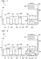
- FIG. 3 A system diagram of a cooling system 102 according to a second example embodiment of the present invention will be described with reference to FIG. 3 .
- the configuration of the cooling system 102 according to the second example embodiment differs from that of the cooling system 101 according to the first example embodiment on the point of changing the rotation speed of the turbo compressor 410 by an inverter 440 to adjust the cooling capacity.
- the inverter 440 when it becomes necessary to change the cooling capacity due to, for example, a fluctuation in the load of the servers, or an addition of servers or maintenance, the inverter 440, it is possible to adjust the cooling capacity by changing the rotation speed of the compressor 410.
- a surge phenomenon may occur in which the fluid flow becomes unstable due to an increase in the ratio of the pressures at the inlet and the outlet (hereinbelow referred to as the pressure ratio). If such a surge phenomenon continues, the compressor itself may be damaged.
- pressure gauges (pressure adjusting means) 451 and 452 for detecting the pressure of the gas-phase refrigerant at the inlet and outlet of the turbo compressor 410, the inverter 440 that controls the rotation speed of the turbo compressor 410, and a hot gas bypass valve 430 that quickly adjusts the pressure fluctuation are provided.
- the inverter 440 has a function of controlling the rotation speed of the turbo compressor 410 on the basis of the pressure ratio of the inlet side pressure and the outlet side pressure detected by the pressure gauges 451 and 452, and a function of a valve control unit that promptly avoids the surge phenomenon by opening the hot gas bypass valve 430 when the pressure ratio becomes equal to or higher than a preset standard set value.
- the hot gas bypass valve 430 is provided in the middle of a bypass pipe 431 that bypasses the turbo compressor 410 and connects the vapor pipe 610 on the inlet side and the vapor pipe 620 on the outlet side to each other, and operates on the basis of a control signal output from the inverter 440.
- a numerical range of the pressure ratio (compression ratio) of the pressure gauges 451 and 452, which assumes all the servers S1 in the server racks 201 to 204 are operated, is preset.
- the pressure ratio between the inlet side and the outlet side of the turbo compressor 410 can be reduced by rotation control of the turbo compressor 410 and the opening operation of the hot gas bypass valve 430 based on the pressure ratio detected by the pressure gauges 451 and 452.
- the turbo compressor 410 can be protected from the surge phenomenon while appropriately adjusting the overall cooling performance in synchronization with the load of the servers S1.
- a centrifugal turbo compressor Depending on the boiling point, pressure, and diversion of the refrigerant, not only a centrifugal turbo compressor but also an axial turbo compressor may be used.
- FIG. 4 A system diagram of a cooling system 103 according to the third example embodiment of the present invention will be described with reference to FIG. 4 .
- the cooling system 103 according to the third example embodiment has a configuration that differs from that of the cooling system 102 according to the second example embodiment in that a refrigerant tank 460 serving as a buffer, a refrigerant pump 470, and flow rate adjusting valves 311 and 321 are sequentially provided on the downstream side of the expansion valve 420.
- the refrigerant tank 460 is for performing gas-liquid separation on the refrigerant supplied from the refrigerant pump 470 and temporary storing the refrigerant, and by separating the refrigerant into a gas phase and a liquid phase and supplying only the liquid-phase refrigerant to the refrigerant pump 470, prevents damage to the refrigerant pump 470.
- a connecting pipe 461 that returns the gas-phase refrigerant that underwent gas-liquid separation in the refrigerant tank 460 to the vapor pipe 610 located on the upstream side of the turbo compressor 410 are provided at the upper portion of the refrigerant tank 460.
- the refrigerant pump 470 is for supplying the liquid-phase refrigerant in the refrigerant tank 460 to the local coolers 310 and 320 that serve as evaporators through the liquid pipe 640.
- the flow rate adjusting valves 311 and 321 are provided in the liquid pipe 640 at locations on the upstream side of the local coolers 310 and 320, respectively, and evenly supply the liquid-phase refrigerant to the local coolers 310 and 320 regardless of the installation layout of the server racks 201 to 204 by individually adjusting the flow rate.
- a centrifugal turbo compressor Depending on the boiling point, pressure, and diversion of the refrigerant, not only a centrifugal turbo compressor but also an axial turbo compressor may be used.
- the cooling system 103 it is possible to evenly supply the liquid-phase refrigerant to the local coolers 310 and 320 and so prevent biased cooling performance regardless of the installation layout of the server racks 201 to 204 by individually adjusting the flow rate adjusting valves 311 and 321 located on the upstream side of the local coolers 310 and 320, respectively.
- the cooling system 103 by temporarily storing the refrigerant on the upstream side of the refrigerant pump 470, it is possible to prevent the cooling pump 470 from being supplied with refrigerant liquid in which gas and liquid are mixed, and so it is possible to prevent the surging phenomenon in the refrigerant pump 470.
- the present invention can be used in a cooling system that efficiently cools electronic devices while preventing damage to devices such as a compressor and heat exchanger as well as a pipe of a refrigerant circulation system.
Landscapes
- Engineering & Computer Science (AREA)
- Microelectronics & Electronic Packaging (AREA)
- Physics & Mathematics (AREA)
- Thermal Sciences (AREA)
- General Engineering & Computer Science (AREA)
- Mechanical Engineering (AREA)
- Computer Hardware Design (AREA)
- Cooling Or The Like Of Electrical Apparatus (AREA)
- Structures Of Non-Positive Displacement Pumps (AREA)
- Ventilation (AREA)
Abstract
Description
- The present invention relates to a cooling system for efficiently exhausting heat from an electronic device that serves as a heat source.
- In a data center where a large number of electronic devices are densely arranged, much heat is expected to be generated, and so a heat exchange system is provided that exhausts heat generated by the electronic devices by adopting a cooling system that achieves heat transfer due to the phase changes of evaporation and condensation of a refrigerant even if a large amount of heat is generated during high-load operation of the electronic devices.
- As this heat exchange system, for example, the cooling system shown in
Patent Document 1, and the indirect refrigerant air conditioner shown inPatent Document 2 are known. - The cooling system shown in
Patent Document 1 includes an equipment room in which a plurality of electronic devices are arranged, an evaporator provided near these electronic devices to cool the electronic devices by vaporizing a refrigerant, a cooling tower that cools and condenses the vaporized refrigerant by means of the outside air, a compressor for compressing the vaporized refrigerant, and a circulation line connected so that the refrigerant circulates between the evaporator, the compressor and the cooling tower. - In the indirect refrigerant air conditioner shown in
Patent Document 2, a constitution is disclosed in which a refrigeration cycle heat exchanger on the heat source side and a thermosiphon heat exchanger on the user side are coupled by a removable heat exchanger, and the refrigerant used in the thermosiphon is a refrigerant having a lower pressure and a lower risk than the refrigerant used in the refrigeration cycle. -
- Patent Document 1:
Japanese Unexamined Patent Application, First Publication No. 2009-193246 -
Patent Document 2Japanese Unexamined Patent Application, First Publication No. H5-203195 -
Patent Documents - However, the heat exchange systems shown in
Patent Documents - The present invention has been made in view of the above circumstances, and provides a cooling system capable of comprehensively improving the efficiency of the evaporation/condensation phase-change cycle of a refrigerant.
- In order to solve the above problem, the present invention proposes the following means.
- A cooling system of the present invention includes a local cooler that is positioned near a heat source and that evaporates a liquid-phase refrigerant by receiving heat from the heat source, a turbo compressor that compresses a gas-phase refrigerant produced in the local cooler, an outdoor unit that condenses the gas-phase refrigerant supplied from the turbo compressor by heat dissipation, and an expansion valve that depressurizes the refrigerant supplied from the outdoor unit and sends the refrigerant to the local cooler, the refrigerant being a low-pressure refrigerant having a condensing pressure lower than a prescribed value.
- The cooling system of the present invention enables efficient operation in evaporation, condensation and handling of a refrigerant.
-
-
FIG. 1 is a schematic configuration diagram of a cooling system according to the present invention. -
FIG. 2 is a schematic configuration diagram of a cooling system according to a first example embodiment of the present invention. -
FIG. 3 is a schematic configuration diagram of a cooling system according to a second example embodiment of the present invention. -
FIG. 4 is a schematic configuration diagram of a cooling system according to a third example embodiment of the present invention. - A
cooling system 10 according to the present invention will be described with reference toFIG. 1 . - The
cooling system 10 mainly includes alocal cooler 1, aturbo compressor 2, anoutdoor unit 3, and anexpansion valve 4. - The
local cooler 1 has aheat exchange unit 5 that is positioned near servers S that serves as heat sources in a server room (upper position of an exhaust area E positioned between the servers S in the figure) to directly receive heat from the server S. Theheat exchange unit 5 of thelocal cooler 1 exhausts heat from the servers S by evaporating an internal liquid-phase refrigerant with the heat of the servers S. - The
turbo compressor 2 is for compressing the gas-phase refrigerant produced in thelocal cooler 1 and forcibly sending the refrigerant to theoutdoor unit 3. For example, a centrifugal compressor in which a plurality of impellers are arranged around a rotating shaft is used. - The
outdoor unit 3 is for condensing the gas-phase refrigerant by performing heat dissipation to an external space on the gas-phase refrigerant supplied from theturbo compressor 2. - The
expansion valve 4 is for depressurizing the refrigerant supplied from theoutdoor unit 3 to obtain a complete liquid-phase refrigerant, and afterward sending the refrigerant to thelocal cooler 1. - As the refrigerant used in the
cooling system 10, a low-pressure refrigerant having a condensing pressure lower than a predetermined value is used. - Specifically, it is possible to use a low-pressure refrigerant with lower condensing pressure than conventional air conditioning refrigerants subject to the High Pressure Gas Safety Act, that is, a low-pressure refrigerant with a high cycle rate not subject to the High Pressure Gas Safety Act, easy to deliver in parts, and not requiring a person qualified in relation to high-pressure gas. Therefore, there is an advantage that it is not necessary to go through troublesome procedures such as equipment inspection each time even if additional work is required, such as when adding the
cooling system 10 with the addition of a server as a heat source. - In addition, when a low-pressure refrigerant is used, since the flow rate per calorific value increases, it is possible to favorably use a turbo compressor, which is superior to a positive displacement compressor in the amount of refrigerant transported per volume (total amount of calorific value to be transported).
- As described in detail above, the
cooling system 10 according to the present invention uses a low-pressure refrigerant with low condensing pressure as the refrigerant, and uses theturbo compressor 2 as a compressor that compresses the refrigerant evaporated by thelocal cooler 1, whereby highly efficient refrigerant compression is possible, and as a result it becomes possible to efficiently exhaust heat from the electronic device in the server S that serves as the heat source. - By using as the refrigerant a low-pressure refrigerant that is not subject to the High Pressure Gas Safety Act, is easy to deliver in parts, and does not require a person qualified in relation to high-pressure gas in the
cooling system 10 of the present invention, efficient refrigerant handling is possible, and operational efficiency can be improved in this respect as well. - In the
cooling system 10 of the present invention, since thelocal cooler 1 positioned near the heat source can directly receive the heat from the electronic device in the server S serving as the heat source to evaporate the liquid-phase refrigerant, efficient heat transfer from the heat source and refrigerant evaporation are possible. - That is, the
cooling system 10 of the present invention enables efficient operation in all of the evaporation, condensation, and handling of the refrigerant. - A system diagram of the
cooling system 101 according to the first example embodiment of the present invention will be described with reference toFIG. 2 . - The
cooling system 101 according to the first example embodiment mainly includeslocal coolers turbo compressor 410, anoutdoor unit 500, and anexpansion valve 420. - In these components, the
local coolers turbo compressor 410 and theoutdoor unit 500 are connected byvapor pipes outdoor unit 500, theexpansion valve 420 and thelocal coolers liquid pipes - In the
cooling system 101, components other than theoutdoor unit 500 are arranged in theserver room 100. - Further, in the
cooling system 101, theturbo compressor 410 and theexpansion valve 420 in theserver room 100 are installed in anindoor unit 400. - The
local coolers heat exchange units - A plurality of the
servers S 1 are housed in server racks 201 to 204 arranged at regular intervals, and the heat is discharged toward an exhaust area E1 located between theserver racks - The
heat exchange units local coolers server racks - The
turbo compressor 410 is for compressing the gas-phase refrigerant generated in thelocal coolers outdoor unit 500. - Specifically, a centrifugal compressor in which a plurality of impellers are arranged around a rotating shaft is used as the
turbo compressor 410, and by compressing and pressurizing the gas-phase refrigerant taken in from the suction nozzle with the centrifugal force when passing through high-speed rotating impellers, the gas-phase refrigerant is discharged from the exhaust nozzle. - The
outdoor unit 500 is for condensing the gas-phase refrigerant by dissipating heat of the gas-phase refrigerant supplied from theturbo compressor 410 to the external space. - The
expansion valve 420 is for depressurizing the refrigerant supplied from theoutdoor unit 500 to obtain a complete liquid-phase refrigerant and then sending the liquid-phase refrigerant to thelocal coolers - Then, in the
cooling system 101 configured as described above, the refrigerant evaporates in theheat exchange units local coolers - As a result, by converting the exhaust gas of the server racks 201 to 204 into cold air with the
local coolers entire server room 100 can be efficiently cooled before the heat diffuses throughout the entire room. - The refrigerant evaporated in the
local coolers turbo compressor 410 through thevapor pipe 610. The refrigerant that is raised to a high temperature and high pressure by theturbo compressor 410 is condensed by dissipating the heat to the outside air in theoutdoor unit 500, and passes through theliquid pipe 630 to move to theexpansion valve 420. The refrigerant depressurized in theexpansion valve 420 becomes liquid-phase refrigerant to be supplied again to thelocal coolers - As the refrigerant used in the
cooling system 101, a low-pressure refrigerant having a condensing pressure lower than a predetermined value is used. - Specifically, the refrigerant used in the
cooling system 101 is a low-pressure refrigerant having a lower condensing pressure than a conventional air-conditioning refrigerant subject to the High Pressure Gas Safety Act (a low-pressure refrigerant with an operating pressure of 1/5 to 1/10 of a conventional refrigerant). That is, a low-pressure fluorocarbon having a high cycle rate that is not subject to the High Pressure Gas Safety Act, is easy to deliver in parts, and does not require a person qualified in relation to high-pressure gas. - It is preferable that the pressure of the refrigerant be a pressure equal to or lower than the pressure that can be used in the flexible pipe for circulating the refrigerant between devices such as server racks in a data center to be cooled in the operating temperature range of the cooling system 101 (so-called withstand pressure), for example, equal to or lower than 0.5 MPaA (absolute pressure). The reason for this is that using a flexible pipe for a pipe between devices improves assemblability and transportability, and generally a flexible pipe has a lower withstand pressure than pipes made of hard materials such as copper pipes and aluminum pipes.
- Depending on the scale (calorific value) of the data center to be cooled, it is conceivable to install just the number of units of a turbo compressor with a cooling capacity of 40 kW, a flow rate of 3 m3/min, an inlet pressure of 0.1 MPaA, and an outlet pressure of 0.3 MPaA to attain the required cooling capacity.
- Further, in the
cooling system 101, since it is necessary to lay the pipes in the immediate vicinity of the server racks 201 to 204, it is necessary to safely perform the laying work even when the servers are in operation. For this reason, in thecooling system 101 of the present example embodiment using the low-pressure refrigerant, since resin pipes that do not need to be welded can be used, in the unlikely event that a pipe is damaged, there is the advantage of less damage to the servers compared to water or a high-pressure refrigerant. - Further, in the present example embodiment, the turbo compressor 410 (centrifugal compressor) is used as the compressor. In this
turbo compressor 410, when a low-pressure refrigerant is used, the flow rate per unit calorific value tends to be higher than that of a normal refrigerant, and there is an advantage in that the flow rate per size is higher than that of a positive displacement compressor such as a scroll compressor. Moreover, since theturbo compressor 410, which is a centrifugal compressor, can be made oil-free, there is an advantage in cleanliness when laying pipes in theserver room 100. - As described in detail above, according to the
cooling system 101 of the first example embodiment, by using a low-pressure refrigerant having a low condensing pressure as the refrigerant, and by using theturbo compressor 410 as a centrifugal compressor that compresses the refrigerant evaporated by thelocal coolers - In the
cooling system 101 according to the first example embodiment, by using as the refrigerant a low-pressure refrigerant that is not subject to the High Pressure Gas Safety Act, is easy to transport in parts, and does not require personnel qualified in relation to high-pressure gas, efficient handling of refrigerant becomes possible, and operational efficiency can be improved in this respect as well. - In the
cooling system 101 according to the first example embodiment, since it is possible to directly receive heat from the electronic device in the server S1 that serves as a heat source with thelocal coolers - That is, in the
cooling system 101 according to the first example embodiment, efficient operation is possible in all of the evaporation, condensation, and handling of the refrigerant. - In the
cooling system 101, theturbo compressor 410 and theexpansion valve 420 are installed in theindoor unit 400 in theserver room 100, but may be arranged outside theserver room 100 together with theoutdoor unit 500. - Although installed above the server racks 201 to 204, the
local coolers local coolers server racks 201 to 204 before diffusing into the server room. Further, theseserver racks 201 to 204 are not limited to the number shown in the drawings. - Depending on the boiling point, pressure, and diversion of the refrigerant, not only a centrifugal turbo compressor but also an axial turbo compressor may be used.
- A system diagram of a
cooling system 102 according to a second example embodiment of the present invention will be described with reference toFIG. 3 . - The configuration of the
cooling system 102 according to the second example embodiment differs from that of thecooling system 101 according to the first example embodiment on the point of changing the rotation speed of theturbo compressor 410 by aninverter 440 to adjust the cooling capacity. - That is, in the
cooling system 101 according to the first example embodiment, when it becomes necessary to change the cooling capacity due to, for example, a fluctuation in the load of the servers, or an addition of servers or maintenance, theinverter 440, it is possible to adjust the cooling capacity by changing the rotation speed of thecompressor 410. - As a specific configuration, in the
turbo compressor 410, a surge phenomenon may occur in which the fluid flow becomes unstable due to an increase in the ratio of the pressures at the inlet and the outlet (hereinbelow referred to as the pressure ratio). If such a surge phenomenon continues, the compressor itself may be damaged. - Therefore, in the second example embodiment, in order to monitor the pressure ratio, which fluctuates due to disturbances such as a fluctuation of the server load, pressure gauges (pressure adjusting means) 451 and 452 for detecting the pressure of the gas-phase refrigerant at the inlet and outlet of the
turbo compressor 410, theinverter 440 that controls the rotation speed of theturbo compressor 410, and a hotgas bypass valve 430 that quickly adjusts the pressure fluctuation are provided. - The
inverter 440 has a function of controlling the rotation speed of theturbo compressor 410 on the basis of the pressure ratio of the inlet side pressure and the outlet side pressure detected by the pressure gauges 451 and 452, and a function of a valve control unit that promptly avoids the surge phenomenon by opening the hotgas bypass valve 430 when the pressure ratio becomes equal to or higher than a preset standard set value. - The hot
gas bypass valve 430 is provided in the middle of abypass pipe 431 that bypasses theturbo compressor 410 and connects thevapor pipe 610 on the inlet side and thevapor pipe 620 on the outlet side to each other, and operates on the basis of a control signal output from theinverter 440. - As the reference setting value, a numerical range of the pressure ratio (compression ratio) of the pressure gauges 451 and 452, which assumes all the servers S1 in the server racks 201 to 204 are operated, is preset.
- Then, when some of a large number of the servers S1 are stopped (for example, for maintenance, server expansion, replacement work, and the like) and the pressure ratio of the pressure gauges 451 and 452 deviates from the reference set pressure, along with controlling the rotation speed of the
turbo compressor 410, the operation of opening the hotgas bypass valve 430 is performed in order to avoid the surge phenomenon. - As described in detail above, in the
cooling system 102 according to the second example embodiment, the pressure ratio between the inlet side and the outlet side of theturbo compressor 410 can be reduced by rotation control of theturbo compressor 410 and the opening operation of the hotgas bypass valve 430 based on the pressure ratio detected by the pressure gauges 451 and 452. - As a result, in the
cooling system 102, theturbo compressor 410 can be protected from the surge phenomenon while appropriately adjusting the overall cooling performance in synchronization with the load of the servers S1. - Depending on the boiling point, pressure, and diversion of the refrigerant, not only a centrifugal turbo compressor but also an axial turbo compressor may be used.
- A system diagram of a
cooling system 103 according to the third example embodiment of the present invention will be described with reference toFIG. 4 . - The
cooling system 103 according to the third example embodiment has a configuration that differs from that of thecooling system 102 according to the second example embodiment in that arefrigerant tank 460 serving as a buffer, arefrigerant pump 470, and flow rate adjusting valves 311 and 321 are sequentially provided on the downstream side of theexpansion valve 420. - The
refrigerant tank 460 is for performing gas-liquid separation on the refrigerant supplied from therefrigerant pump 470 and temporary storing the refrigerant, and by separating the refrigerant into a gas phase and a liquid phase and supplying only the liquid-phase refrigerant to therefrigerant pump 470, prevents damage to therefrigerant pump 470. - Further, a connecting
pipe 461 that returns the gas-phase refrigerant that underwent gas-liquid separation in therefrigerant tank 460 to thevapor pipe 610 located on the upstream side of theturbo compressor 410 are provided at the upper portion of therefrigerant tank 460. - The
refrigerant pump 470 is for supplying the liquid-phase refrigerant in therefrigerant tank 460 to thelocal coolers liquid pipe 640. - The flow rate adjusting valves 311 and 321 are provided in the
liquid pipe 640 at locations on the upstream side of thelocal coolers local coolers - Depending on the boiling point, pressure, and diversion of the refrigerant, not only a centrifugal turbo compressor but also an axial turbo compressor may be used.
- As described in detail above, in the
cooling system 103 according to the third example embodiment, it is possible to evenly supply the liquid-phase refrigerant to thelocal coolers local coolers - In the
cooling system 103 according to the third example embodiment, by temporarily storing the refrigerant on the upstream side of therefrigerant pump 470, it is possible to prevent thecooling pump 470 from being supplied with refrigerant liquid in which gas and liquid are mixed, and so it is possible to prevent the surging phenomenon in therefrigerant pump 470. - Although the example embodiments of the present invention have been described in detail with reference to the drawings, specific configurations are not limited to these example embodiments, and design changes and the like within a range not deviating from the gist of the present invention are also included.
- The present invention can be used in a cooling system that efficiently cools electronic devices while preventing damage to devices such as a compressor and heat exchanger as well as a pipe of a refrigerant circulation system.
-
- 1: Local cooler
- 2: Turbo compressor
- 3: Outdoor unit
- 4: Expansion value
- 5: Heat exchange unit
- 10: Cooling system
- 100: Server room
- 101: Cooling system
- 102: Cooling system
- 103: Cooling system
- 201: Server rack
- 202: Server rack
- 203: Server rack
- 204: Server rack
- 310: Local cooler
- 311: Flow rate adjusting valve
- 320: Local cooler
- 321: Flow rate adjusting valve
- 410: Turbo compressor
- 420: Expansion valve
- 430: Hot gas bypass valve
- 431: Bypass pipe
- 440: Inverter
- 451: Pressure gauge
- 452: Pressure gauge
- 460: Refrigerant tank
- 470: Refrigerant pump
- 500: Outdoor unit
- 610: Vapor pipe
- 620: Vapor pipe
- 630: Liquid pipe
- 640: Liquid pipe
- S: Server
- S1: Server
- E: Exhaust area
- E1: Exhaust area
Claims (9)
- A cooling system comprising:a local cooler that is positioned near a heat source and evaporates a liquid-phase refrigerant by receiving heat from the heat source;a turbo compressor that compresses a gas-phase refrigerant that absorbed the heat in the local cooler;an outdoor unit that condenses the gas-phase refrigerant supplied from the turbo compressor by heat dissipation; andan expansion valve that depressurizes the refrigerant supplied from the outdoor unit and sends the refrigerant to the local cooler,wherein the refrigerant is a low-pressure refrigerant having a condensing pressure lower than a predetermined value.
- The cooling system according to claim 1, wherein the local cooler includes a heat exchange unit that is installed above an exhaust area between server racks and that directly receives the heat from a server that serves as the heat source.
- The cooling system according to either one of claims 1 or 2, wherein the turbo compressor is a centrifugal compressor in which a plurality of impellers are arranged around a rotating shaft.
- The cooling system according to any one of claims 1 to 3, further comprising:a pressure detecting means that is provided in each of an inlet side pipe and an outlet side pipe of the turbo compressor and detects pressure of the gas-phase refrigerant supplied from the local cooler; anda pressure control unit that controls rotation speed of the turbo compressor based on a pressure ratio of inlet side pressure and outlet side pressure detected by the pressure detecting means.
- The cooling system according to claim 4,wherein a bypass pipe is installed, the bypass pipe connecting the inlet side pipe and the outlet side pipe to each other so as to bypass the turbo compressor and including a hot gas bypass valve in a middle thereof, andthe pressure control unit controls opening and closing of the hot gas bypass valve together with the rotation speed of the turbo compressor based on the pressure ratio of the inlet side pressure and the outlet side pressure detected by the pressure detecting means.
- The cooling system according to claim 5, wherein the pressure control unit performs open operation of the hot gas bypass valve when the pressure ratio of the inlet side pressure and the outlet side pressure detected by the pressure detecting means exceeds a predetermined reference set value related to a surge phenomenon.
- The cooling system according to any one of claims 1 to 6,wherein a plurality of local coolers are installed corresponding to the heat source, anda flow rate adjusting valve that adjusts a supply amount of the liquid-phase refrigerant is respectively provided in a middle of a refrigerant supply pipe that supplies the liquid-phase refrigerant to the local coolers.
- The cooling system according to claim 7,wherein a refrigerant supply pump that supplies the liquid-phase refrigerant to the local coolers is provided between the flow rate adjusting valve and the expansion valve, anda refrigerant tank that temporarily stores the refrigerant is installed on an inlet side of the refrigerant supply pump.
- The cooling system according to claim 8, wherein a connecting pipe is installed at an upper portion of the refrigerant tank, the connecting pipe guiding a gas-phase component separated from the refrigerant supplied to the refrigerant tank to an upstream side of the compressor.
Applications Claiming Priority (1)
| Application Number | Priority Date | Filing Date | Title |
|---|---|---|---|
| PCT/JP2019/027100 WO2021005701A1 (en) | 2019-07-09 | 2019-07-09 | Cooling system |
Publications (2)
| Publication Number | Publication Date |
|---|---|
| EP3998435A1 true EP3998435A1 (en) | 2022-05-18 |
| EP3998435A4 EP3998435A4 (en) | 2022-06-29 |
Family
ID=74114464
Family Applications (1)
| Application Number | Title | Priority Date | Filing Date |
|---|---|---|---|
| EP19937218.6A Withdrawn EP3998435A4 (en) | 2019-07-09 | 2019-07-09 | Cooling system |
Country Status (5)
| Country | Link |
|---|---|
| US (1) | US11825630B2 (en) |
| EP (1) | EP3998435A4 (en) |
| JP (2) | JP6935858B2 (en) |
| AU (1) | AU2019456022B2 (en) |
| WO (1) | WO2021005701A1 (en) |
Cited By (1)
| Publication number | Priority date | Publication date | Assignee | Title |
|---|---|---|---|---|
| EP4729852A1 (en) * | 2024-10-16 | 2026-04-22 | Vertiv Corporation | Refrigerant management system for hybrid air/liquid cooling unit |
Families Citing this family (7)
| Publication number | Priority date | Publication date | Assignee | Title |
|---|---|---|---|---|
| JP7364090B2 (en) * | 2019-10-02 | 2023-10-18 | 日本電気株式会社 | Server rack cooling systems, attachments, and air removal methods |
| US12526960B2 (en) | 2021-06-30 | 2026-01-13 | Nvidia Corporation | In-rack refrigerant distribution unit with pressure control system |
| CN113710070B (en) * | 2021-09-04 | 2022-02-22 | 宁波纬度通信设备有限公司 | Intelligent network cabinet with cooling circulation system |
| KR102584496B1 (en) * | 2021-11-03 | 2023-10-05 | 한국가스공사 | Cooling System For a Data Center Employing LNG Cold Energy |
| WO2023181117A1 (en) * | 2022-03-22 | 2023-09-28 | 日本電気株式会社 | Cooling device, and cooling method for cooling device |
| KR102783365B1 (en) * | 2023-04-26 | 2025-03-19 | 한국가스공사 | Apparatus and Method for Cooling Data Center |
| CN119545767B (en) * | 2025-01-22 | 2025-06-10 | 东莞市立敏达电子科技有限公司 | Cooling liquid distribution assembly for cooling plate and cooling plate |
Family Cites Families (15)
| Publication number | Priority date | Publication date | Assignee | Title |
|---|---|---|---|---|
| JP3063348B2 (en) | 1992-01-29 | 2000-07-12 | 株式会社日立製作所 | Indirect refrigerant air conditioner, detachable heat exchanger for indirect refrigerant air conditioner, and indirect refrigerant air conditioning method |
| JP3674974B2 (en) | 1995-01-19 | 2005-07-27 | アイシン精機株式会社 | Water cooler |
| NO970066D0 (en) | 1997-01-08 | 1997-01-08 | Norild As | Cooling system with closed circulation circuit |
| JP5041343B2 (en) | 2008-02-13 | 2012-10-03 | 株式会社日立プラントテクノロジー | Electronic equipment cooling system |
| JP5403980B2 (en) | 2008-09-19 | 2014-01-29 | インターナショナル・ビジネス・マシーンズ・コーポレーション | Apparatus and method for facilitating cooling of an electronic equipment rack using a water refrigerant compression system |
| TWI379041B (en) * | 2009-02-13 | 2012-12-11 | Ind Tech Res Inst | Method and system for controling compressor |
| JP6008206B2 (en) | 2012-01-18 | 2016-10-19 | パナソニックIpマネジメント株式会社 | Refrigeration cycle equipment |
| CA2898424C (en) * | 2013-02-12 | 2017-09-12 | Hachiyo Engineering Co., Ltd. | Cooling mechanism for data center |
| ITFI20130064A1 (en) * | 2013-03-26 | 2014-09-27 | Nuovo Pignone Srl | "METHODS AND SYSTEMS FOR CONTROLLING TURBOCOMPRESSORS" |
| JP5584333B1 (en) * | 2013-07-16 | 2014-09-03 | 新日鉄住金エンジニアリング株式会社 | Server rack indoor system |
| JP6884507B2 (en) * | 2016-01-13 | 2021-06-09 | 三菱重工サーマルシステムズ株式会社 | Turbo compressor, turbo refrigerator equipped with this |
| EP3418651A4 (en) | 2016-02-19 | 2019-10-16 | Agc Inc. | CALORIFIC CYCLE SYSTEM AND CALORIFIC CYCLE METHOD USING THE SAME |
| JP6719370B2 (en) | 2016-12-07 | 2020-07-08 | 三菱重工サーマルシステムズ株式会社 | Heat source system, control device, control method, and program |
| JP6778884B2 (en) * | 2017-01-16 | 2020-11-04 | パナソニックIpマネジメント株式会社 | Refrigeration cycle equipment |
| US10126022B1 (en) * | 2017-05-05 | 2018-11-13 | Cooper Research, Llc | Refrigeration warming system for refrigeration systems |
-
2019
- 2019-07-09 EP EP19937218.6A patent/EP3998435A4/en not_active Withdrawn
- 2019-07-09 AU AU2019456022A patent/AU2019456022B2/en not_active Ceased
- 2019-07-09 US US17/624,910 patent/US11825630B2/en active Active
- 2019-07-09 WO PCT/JP2019/027100 patent/WO2021005701A1/en not_active Ceased
- 2019-07-09 JP JP2021527872A patent/JP6935858B2/en active Active
-
2021
- 2021-08-20 JP JP2021135165A patent/JP7338664B2/en active Active
Cited By (1)
| Publication number | Priority date | Publication date | Assignee | Title |
|---|---|---|---|---|
| EP4729852A1 (en) * | 2024-10-16 | 2026-04-22 | Vertiv Corporation | Refrigerant management system for hybrid air/liquid cooling unit |
Also Published As
| Publication number | Publication date |
|---|---|
| US20220279682A1 (en) | 2022-09-01 |
| AU2019456022B2 (en) | 2023-10-19 |
| EP3998435A4 (en) | 2022-06-29 |
| JP2022001821A (en) | 2022-01-06 |
| JP6935858B2 (en) | 2021-09-15 |
| AU2019456022A1 (en) | 2022-02-03 |
| WO2021005701A1 (en) | 2021-01-14 |
| JP7338664B2 (en) | 2023-09-05 |
| JPWO2021005701A1 (en) | 2021-09-27 |
| US11825630B2 (en) | 2023-11-21 |
Similar Documents
| Publication | Publication Date | Title |
|---|---|---|
| US11825630B2 (en) | Cooling system | |
| US20120174609A1 (en) | Heat source system | |
| US20120048514A1 (en) | Cooling systems and methods | |
| EP3320217B1 (en) | Compressor system with a cooling arrangement between the anti-surge valve and the compressor suction side and relevant method | |
| EP3320212B1 (en) | Compressor system with a gas temperature control at the inlet of the anti-surge line and relevant method | |
| US11009266B2 (en) | Integrated refrigeration and air conditioning system | |
| US12038213B2 (en) | Refrigeration cycle apparatus | |
| US20180356130A1 (en) | Cascading heat recovery using a cooling unit as a source | |
| US20250071943A1 (en) | Active/passive cooling system with pumped refrigerant | |
| WO2019173330A1 (en) | Cascade system for use in economizer compressor and related methods | |
| US11976857B2 (en) | Refrigeration cycle device | |
| JP2013167368A (en) | Air conditioner | |
| EP3998434A1 (en) | Cooling system, surge generation prevention device, surge generation prevention method, and surge generation prevention program | |
| KR20170073457A (en) | Air conditioner outdoor unit including heat exchange apparatus | |
| JP7164068B1 (en) | Cooling device and cooling control method | |
| WO2023042906A1 (en) | Cooling device and cavitation prevention method | |
| WO2023181117A1 (en) | Cooling device, and cooling method for cooling device | |
| GB2579928A (en) | Heat pump having closed intermediate cooling and method for pumping heat or method for producing the heat pump |
Legal Events
| Date | Code | Title | Description |
|---|---|---|---|
| STAA | Information on the status of an ep patent application or granted ep patent |
Free format text: STATUS: THE INTERNATIONAL PUBLICATION HAS BEEN MADE |
|
| PUAI | Public reference made under article 153(3) epc to a published international application that has entered the european phase |
Free format text: ORIGINAL CODE: 0009012 |
|
| STAA | Information on the status of an ep patent application or granted ep patent |
Free format text: STATUS: REQUEST FOR EXAMINATION WAS MADE |
|
| 17P | Request for examination filed |
Effective date: 20220114 |
|
| AK | Designated contracting states |
Kind code of ref document: A1 Designated state(s): AL AT BE BG CH CY CZ DE DK EE ES FI FR GB GR HR HU IE IS IT LI LT LU LV MC MK MT NL NO PL PT RO RS SE SI SK SM TR |
|
| A4 | Supplementary search report drawn up and despatched |
Effective date: 20220601 |
|
| RIC1 | Information provided on ipc code assigned before grant |
Ipc: F25B 49/02 20060101ALI20220525BHEP Ipc: F25B 49/00 20060101ALI20220525BHEP Ipc: F25B 1/053 20060101ALI20220525BHEP Ipc: F25B 39/02 20060101ALI20220525BHEP Ipc: F24F 7/06 20060101ALI20220525BHEP Ipc: F25B 1/00 20060101AFI20220525BHEP |
|
| DAV | Request for validation of the european patent (deleted) | ||
| DAX | Request for extension of the european patent (deleted) | ||
| STAA | Information on the status of an ep patent application or granted ep patent |
Free format text: STATUS: EXAMINATION IS IN PROGRESS |
|
| 17Q | First examination report despatched |
Effective date: 20231025 |
|
| STAA | Information on the status of an ep patent application or granted ep patent |
Free format text: STATUS: THE APPLICATION HAS BEEN WITHDRAWN |
|
| 18W | Application withdrawn |
Effective date: 20240214 |