EP3998431A1 - Heat recovery device - Google Patents
Heat recovery device Download PDFInfo
- Publication number
- EP3998431A1 EP3998431A1 EP19936640.2A EP19936640A EP3998431A1 EP 3998431 A1 EP3998431 A1 EP 3998431A1 EP 19936640 A EP19936640 A EP 19936640A EP 3998431 A1 EP3998431 A1 EP 3998431A1
- Authority
- EP
- European Patent Office
- Prior art keywords
- heat
- terminal
- recovery
- heat exchanger
- utilization
- Prior art date
- Legal status (The legal status is an assumption and is not a legal conclusion. Google has not performed a legal analysis and makes no representation as to the accuracy of the status listed.)
- Granted
Links
Images



Classifications
-
- F—MECHANICAL ENGINEERING; LIGHTING; HEATING; WEAPONS; BLASTING
- F24—HEATING; RANGES; VENTILATING
- F24D—DOMESTIC- OR SPACE-HEATING SYSTEMS, e.g. CENTRAL HEATING SYSTEMS; DOMESTIC HOT-WATER SUPPLY SYSTEMS; ELEMENTS OR COMPONENTS THEREFOR
- F24D11/00—Central heating systems using heat accumulated in storage masses
- F24D11/02—Central heating systems using heat accumulated in storage masses using heat pumps
- F24D11/0214—Central heating systems using heat accumulated in storage masses using heat pumps water heating system
-
- F—MECHANICAL ENGINEERING; LIGHTING; HEATING; WEAPONS; BLASTING
- F24—HEATING; RANGES; VENTILATING
- F24D—DOMESTIC- OR SPACE-HEATING SYSTEMS, e.g. CENTRAL HEATING SYSTEMS; DOMESTIC HOT-WATER SUPPLY SYSTEMS; ELEMENTS OR COMPONENTS THEREFOR
- F24D19/00—Details
- F24D19/10—Arrangement or mounting of control or safety devices
- F24D19/1006—Arrangement or mounting of control or safety devices for water heating systems
- F24D19/1009—Arrangement or mounting of control or safety devices for water heating systems for central heating
- F24D19/1039—Arrangement or mounting of control or safety devices for water heating systems for central heating the system uses a heat pump
-
- F—MECHANICAL ENGINEERING; LIGHTING; HEATING; WEAPONS; BLASTING
- F24—HEATING; RANGES; VENTILATING
- F24H—FLUID HEATERS, e.g. WATER OR AIR HEATERS, HAVING HEAT-GENERATING MEANS, e.g. HEAT PUMPS, IN GENERAL
- F24H4/00—Fluid heaters characterised by the use of heat pumps
- F24H4/02—Water heaters
- F24H4/04—Storage heaters
-
- F—MECHANICAL ENGINEERING; LIGHTING; HEATING; WEAPONS; BLASTING
- F24—HEATING; RANGES; VENTILATING
- F24H—FLUID HEATERS, e.g. WATER OR AIR HEATERS, HAVING HEAT-GENERATING MEANS, e.g. HEAT PUMPS, IN GENERAL
- F24H7/00—Storage heaters, i.e. heaters in which the energy is stored as heat in masses for subsequent release
- F24H7/02—Storage heaters, i.e. heaters in which the energy is stored as heat in masses for subsequent release the released heat being conveyed to a transfer fluid
- F24H7/04—Storage heaters, i.e. heaters in which the energy is stored as heat in masses for subsequent release the released heat being conveyed to a transfer fluid with forced circulation of the transfer fluid
-
- F—MECHANICAL ENGINEERING; LIGHTING; HEATING; WEAPONS; BLASTING
- F24—HEATING; RANGES; VENTILATING
- F24D—DOMESTIC- OR SPACE-HEATING SYSTEMS, e.g. CENTRAL HEATING SYSTEMS; DOMESTIC HOT-WATER SUPPLY SYSTEMS; ELEMENTS OR COMPONENTS THEREFOR
- F24D2200/00—Heat sources or energy sources
- F24D2200/12—Heat pump
- F24D2200/123—Compression type heat pumps
-
- F—MECHANICAL ENGINEERING; LIGHTING; HEATING; WEAPONS; BLASTING
- F24—HEATING; RANGES; VENTILATING
- F24D—DOMESTIC- OR SPACE-HEATING SYSTEMS, e.g. CENTRAL HEATING SYSTEMS; DOMESTIC HOT-WATER SUPPLY SYSTEMS; ELEMENTS OR COMPONENTS THEREFOR
- F24D2200/00—Heat sources or energy sources
- F24D2200/16—Waste heat
-
- F—MECHANICAL ENGINEERING; LIGHTING; HEATING; WEAPONS; BLASTING
- F24—HEATING; RANGES; VENTILATING
- F24D—DOMESTIC- OR SPACE-HEATING SYSTEMS, e.g. CENTRAL HEATING SYSTEMS; DOMESTIC HOT-WATER SUPPLY SYSTEMS; ELEMENTS OR COMPONENTS THEREFOR
- F24D2200/00—Heat sources or energy sources
- F24D2200/16—Waste heat
- F24D2200/20—Sewage water
-
- Y—GENERAL TAGGING OF NEW TECHNOLOGICAL DEVELOPMENTS; GENERAL TAGGING OF CROSS-SECTIONAL TECHNOLOGIES SPANNING OVER SEVERAL SECTIONS OF THE IPC; TECHNICAL SUBJECTS COVERED BY FORMER USPC CROSS-REFERENCE ART COLLECTIONS [XRACs] AND DIGESTS
- Y02—TECHNOLOGIES OR APPLICATIONS FOR MITIGATION OR ADAPTATION AGAINST CLIMATE CHANGE
- Y02B—CLIMATE CHANGE MITIGATION TECHNOLOGIES RELATED TO BUILDINGS, e.g. HOUSING, HOUSE APPLIANCES OR RELATED END-USER APPLICATIONS
- Y02B10/00—Integration of renewable energy sources in buildings
- Y02B10/70—Hybrid systems, e.g. uninterruptible or back-up power supplies integrating renewable energies
Definitions
- the present invention relates to a heat recovery apparatus that recovers heat from a terminal that utilizes heat.
- Patent Literature 1 discloses a heat recovery apparatus that recovers heat from a remaining hot water in a bathtub with an improved efficiency.
- the heat recovery apparatus described in Patent Literature 1 includes a hot water storage tank for storing, as hot water, heat that is used when a user takes a shower or fills the bathtub with hot water, and a heat storage material for recovering residual heat of the bathtub.
- the heat recovery apparatus recovers residual heat of the bathtub by using latent heat of the heat storage material.
- Patent Literature 1 Japanese Unexamined Patent Application Publication JP 2010-7935 A
- Patent Literature 1 uses a heat storage material utilizing latent heat for recovering heat from a bathtub, that is, for storing a heat of 10 MJ, a large heat storage tank is required for supplying hot water for a heat amount of 70 MJ. Consequently, it is difficult to reduce the size of the entire apparatus.
- the present invention has been made to solve the problem described above, and has an object to provide a heat recovery apparatus with a reduced size.
- a heat recovery apparatus is configured to recover residual heat of a terminal that is connected to the heat recovery apparatus and utilizes heat.
- the heat recovery apparatus includes a terminal circuit to which the terminal is connected and configured to supply heat to the terminal by allowing terminal fluid to circulate in the terminal circuit, a recovery circuit in which recovery fluid circulates and configured to recover residual heat of the terminal, a heat source circuit in which refrigerant circulates and configured to generate heat by using heat recovered in the recovery circuit, a heat storage circuit in which heat storage fluid circulates and configured to reject the heat generated in the heat source circuit to a heat storage material, and a heat storage tank that houses the heat storage material.
- the heat storage material includes at least a latent heat storage material or a high-polymer heat storage material.
- a latent heat storage material or a high-polymer heat storage material is used as the heat storage material for storing heat.
- the heat storage tank storing the heat storage material can be made smaller, and the entire apparatus thus can be made smaller.
- the heat recovery apparatus according to Embodiment 1 is configured to store heat from a heat source and enable a terminal connected to the heat recovery apparatus to utilize the stored heat.
- FIG. 1 is a circuit diagram illustrating an example of the configuration of a heat recovery apparatus 100 according to Embodiment 1.
- the heat recovery apparatus 100 mainly includes a heat source unit 1, a heat storage unit 2, a utilization unit 3, a terminal unit 4, a recovery unit 5, and a controller 110.
- a terminal 1000 to be used by a user is connected to the heat recovery apparatus 100.
- the terminal 1000 utilizes heat stored in the heat recovery apparatus 100 to perform heating or other operation.
- the terminal 1000 is a floor heating panel, for example, but is not limited to a floor heating panel.
- the terminal 1000 may be a panel heater or a heating radiator, for example.
- the terminal 1000 may be a bathtub. In this case, the heat recovery apparatus 100 is used to heat hot water in the bathtub for reheating and to keep the hot water hot.
- the heat source unit 1 includes a compressor 11, a heat source heat exchanger 6, an air expansion mechanism 12, an air heat receiving heat exchanger 13, an expansion mechanism 14 for recovery, and a heat receiving heat exchanger 9 for recovery.
- the heat source unit 1 is provided with an air heat source pipe 10A to which the compressor 11, the heat source heat exchanger 6, the air expansion mechanism 12, and the air heat receiving heat exchanger 13 are connected.
- An air heat source circuit, through which refrigerant circulates, is formed by sequentially connecting the compressor 11, the heat source heat exchanger 6, the air expansion mechanism 12, and the air heat receiving heat exchanger 13 by the air heat source pipe 10A.
- the heat source unit 1 is provided with a recovery heat source pipe 10B, which branches off at a point between a refrigerant outflow side of the heat source heat exchanger 6 and a refrigerant inflow side of the air expansion mechanism 12 and joins at a point between a refrigerant outflow side of the air heat receiving heat exchanger 13 and a suction side of the compressor 11.
- An expansion mechanism 14 for recovery and a heat receiving heat exchanger 9 for recovery are connected to the recovery heat source pipe 10B.
- a recovery heat source circuit through which refrigerant circulates, is formed by sequentially connecting the compressor 11, the heat source heat exchanger 6, the expansion mechanism 14 for recovery, and the heat receiving heat exchanger 9 for recovery by the recovery heat source pipe 10B and a part of the air heat source pipe 10A.
- a hydrofluorocarbon (HFC) refrigerant such as R410A and R32, or a natural refrigerant such as carbon dioxide (CO 2 ) and propane can be used, for example.
- HFC hydrofluorocarbon
- CO 2 carbon dioxide
- propane propane
- the type of the refrigerant is not limited to the refrigerants, and any other refrigerant may be used.
- the compressor 11 is configured to suction refrigerant in a low-temperature and low-pressure state, compress the suctioned refrigerant, and then discharge the refrigerant in a high-temperature and high-pressure state.
- the compressor 11 is, for example, an inverter compressor in which a capacity, which is a delivery amount per unit time, is controlled by changing an operation frequency.
- the operation frequency of the compressor 11 is controlled by the controller 110.
- the heat source heat exchanger 6 is configured to exchange heat between the refrigerant flowing in the air heat source circuit or the recovery heat source circuit connected to a refrigerant side flow path and heat storage fluid flowing in a heat storage circuit, which will be described later, connected to a liquid side flow path.
- the refrigerant rejects heat to the heat storage fluid.
- the air expansion mechanism 12 is configured to expand the refrigerant that has flowed out from the heat source heat exchanger 6, thereby reducing the temperature and the pressure of the refrigerant.
- the air expansion mechanism 12 is also configured to close the flow path of the refrigerant so that flow of the refrigerant can be blocked.
- the air expansion mechanism 12 is, for example, a valve capable of controlling its opening degree, such as an electronic expansion valve. The opening degree of the air expansion mechanism 12 is controlled by the controller 110.
- the air heat receiving heat exchanger 13 is configured to exchange heat between outdoor air supplied by a fan, which is not shown, and the refrigerant. In the air heat receiving heat exchanger 13, the refrigerant receives heat from the outdoor air, thereby evaporating.
- the expansion mechanism 14 for recovery is configured to expand the refrigerant that has flowed out from the heat source heat exchanger 6, thereby reducing the temperature and the pressure of the refrigerant.
- the expansion mechanism 14 for recovery is also configured to close the flow path of the refrigerant so that flow of the refrigerant can be blocked.
- the expansion mechanism 14 for recovery is, for example, a valve capable of controlling its opening degree, such as an electronic expansion valve. The opening degree of the expansion mechanism 14 for recovery is controlled by the controller 110.
- the heat receiving heat exchanger 9 for recovery is configured to exchange heat between the refrigerant flowing in the recovery heat source circuit connected to a refrigerant side flow path and recovery fluid flowing in a recovery circuit, which will be described later, connected to a liquid side flow path.
- the refrigerant receives heat from the recovery fluid, thereby evaporating.
- the heat source unit 1 is provided with an outdoor air temperature sensor 15 and an evaporation temperature sensor 16.
- the outdoor air temperature sensor 15 is installed near the air heat receiving heat exchanger 13 and is configured to detect the temperature of outdoor air supplied to the air heat receiving heat exchanger 13.
- the evaporation temperature sensor 16 is installed near the heat receiving heat exchanger 9 for recovery and is configured to detect the evaporation temperature of the refrigerant at which the refrigerant evaporates.
- the heat storage unit 2 includes the heat source heat exchanger 6, a heat storage pump 21, a heat storage tank 7, and a heat storage heat exchanger 22.
- the heat storage unit 2 is provided with a heat storage pipe 20 to which the heat source heat exchanger 6, the heat storage heat exchanger 22, and the heat storage pump 21 are connected.
- a heat storage circuit, through which heat storage fluid circulates, is formed by sequentially connecting the heat source heat exchanger 6, the heat storage heat exchanger 22, and the heat storage pump 21 by the heat storage pipe 20.
- the heat storage fluid water or antifreeze can be used, for example.
- the heat storage tank 7 is formed into a cuboid shape, for example. Inside the heat storage tank 7, a heat storage material 7a, the heat storage heat exchanger 22, and a utilization heat exchanger 33, which will be described later, are housed.
- the heat storage material 7a is a material that has a larger heat storage amount per volume than that of water (hot water).
- the heat storage material 7a is housed in the heat storage tank 7 so as to fill the inside of the heat storage tank 7.
- the heat storage material 7a includes, for example, a latent heat storage material that stores and releases heat by using latent heat associated with a phase change of the material between a solid state and a liquid state, or a high-polymer heat storage material that stores and releases heat by using reaction heat generated when a high-polymer adsorbs and desorbs water molecules.
- a latent heat storage material stores heat by using latent heat of the heat storage material, the thermal capacity per volume is larger than that of a case where water is used to store heat (that is a case of sensible heat storage).
- the heat storage material 7a includes a latent heat storage material
- examples of the latent heat storage material include paraffins, sugar alcohols such as erythritol, and hydrated salts such as sodium acetate trihydrate.
- the whole amount of the heat storage material 7a need not be a latent heat storage material, and may be a mixed material of a latent heat storage material and water. Even by using such a mixed material of a latent heat storage material and water, latent heat of the latent heat storage material can be utilized, and the heat storage amount per volume is thus larger than that of a case where only water is used. Furthermore, a high-polymer heat storage material that stores and releases heat by using reaction heat generated when a high-polymer adsorbs and desorbs water molecules may be used as the heat storage material 7a. This is because the reaction heat of such a high-polymer heat storage material is larger than sensible heat storage utilizing only water.
- the high-polymer heat storage material has at least a high-polymer and water, and is, for example, a temperature-responsive gel.
- the high-polymer is a temperature-responsive high-polymer that exhibits hydrophilicity and hydrophobicity depending on a temperature.
- the temperature is a lower critical solution temperature (LCST) for the water.
- LCST critical solution temperature
- the high-polymer exhibits hydrophilicity at a temperature below the LCST, and exhibits hydrophobicity at a temperature above the LCST.
- high-polymer are high-density cross-linked products, such as poly(N-ethyl(meth)acrylamide), poly(N-n-propyl(meth)acrylamide), poly(N-isopropyl(meth)acrylamide), poly(N-cyclopropyl(meth)acrylamide), poly(N,N-dimethyl(meth)acrylamide, poly(N-ethyl-N-methyl(meth)acrylamide), poly(N-methyl-N-n-propyl(meth)acrylamide), poly(N-isopropyl-N-methyl(meth)acrylamide), poly(N,N-diethyl(meth)acrylamide), poly(N-(meth)acryloylpyrrolidine), poly(N-(meth)acryloylpiperidine), poly(N-ethoxyethyl(meth)acrylamide), poly(N-ethyl-N-methoxyethyl(meth)acrylamide), poly(N-eth
- the water is preferably pure water but is not limited to pure water.
- the water may be water that does not contain a component that may degrade the high-polymer.
- the water is classified into bound water that is bound to a high-density cross-linked product of the high-polymer and free water that excludes the bound water. Because the high-polymer has a hydrophilic swelling structure at a temperature below the LCST, bound water of the water forms a stable high-order molecular sequence to increase the hydrogen bonding strength.
- the high-polymer has a hydrophobic shrinking structure at a temperature above the LCST, bound water of the water forms an unstable low-order molecular sequence to reduce the hydrogen bonding strength. That is, in the heat storage material 7a, the hydrogen bonding strength of bound water can be enhanced or reduced around the LCST. Because the hydrogen bonding strength of bound water in the heat storage material 7a can be varied around the LCST, the heat storage material 7a has a large heat storage amount corresponding to the variation of the hydrogen bonding strength.
- the heat storage material 7a including a latent heat storage material or a high-polymer heat storage material has a large heat storage amount, the filling amount of the heat storage material 7a filled in the heat storage tank 7 cab be reduced. Therefore, the heat recovery apparatus 100 can be made smaller.
- the heat storage pump 21 is configured to be driven by a motor, which is not shown, and send and supply the heat storage liquid that has flowed out from the heat storage heat exchanger 22 to a liquid side flow path of the heat source heat exchanger 6.
- the rotation frequency of the heat storage pump 21 is controlled by the controller 110.
- the heat storage heat exchanger 22 is configured to exchange heat between the heat storage fluid flowing in the heat storage heat exchanger 22 and the heat storage material 7a filled in the heat storage tank 7.
- the heat storage fluid rejects heat to the heat storage material 7a in the heat storage heat exchanger 22. The heat storage material 7a is thus heated.
- the utilization unit 3 includes a utilization pump 31, a flow switching device 32, the utilization heat exchanger 33, and a terminal heat exchanger 8.
- the utilization unit 3 is provided with a utilization pipe 30 to which the utilization pump 31, the flow switching device 32, the utilization heat exchanger 33, and the terminal heat exchanger 8 are connected.
- a utilization circuit, through which utilization fluid circulates, is formed by sequentially connecting the utilization pump 31, the flow switching device 32, the utilization heat exchanger 33, and the terminal heat exchanger 8 by the utilization pipe 30.
- the utilization fluid water or antifreeze can be used, for example.
- the utilization pump 31 is configured to be driven by a motor, which is not shown, and send and supply the utilization fluid that has flowed out from the terminal heat exchanger 8 to the flow switching device 32.
- the rotation frequency of the utilization pump 31 is controlled by the controller 110.
- the flow switching device 32 is, for example, a three-way valve, and is configured to switch flow directions of the fluid by making flow paths in two directions, out of three directions, communicate with each other while blocking a flow path of the remaining one direction.
- the flow switching device 32 is installed either between the utilization heat exchanger 33 and the utilization pump 31 or between the utilization heat exchanger 33 and the terminal heat exchanger 8.
- the flow switching device 32 is installed between the utilization heat exchanger 33 and the utilization pump 31.
- the flow switching device 32 is switched as shown by the solid line of FIG. 1 , so that a discharge side of the utilization pump 31 and the utilization heat exchanger 33 communicate with each other. Switching of the flow paths in the flow switching device 32 is controlled by the controller 110.
- the utilization heat exchanger 33 is configured to exchange heat between the utilization fluid flowing in the utilization heat exchanger 33 and the heat storage material 7a filled in the heat storage tank 7.
- the utilization fluid receives heat from the heat storage material 7a, in which heat is stored, in the utilization heat exchanger 33. The utilization fluid is thus heated.
- the terminal heat exchanger 8 is configured to exchange heat between the utilization fluid flowing in the utilization circuit and terminal fluid flowing in a terminal circuit, which will be described later.
- the utilization fluid rejects heat to the terminal fluid in the terminal heat exchanger 8. The terminal fluid is thus heated.
- the terminal unit 4 includes a terminal pump 41 and the terminal heat exchanger 8.
- the terminal unit 4 is provided with a terminal pipe 40 to which the terminal pump 41, the terminal heat exchanger 8, and the terminal 1000, which is provided outside the heat recovery apparatus 100, are connected.
- a terminal circuit, through which the terminal fluid circulates, is formed by sequentially connecting the terminal pump 41, the terminal heat exchanger 8, and the terminal 1000 by the terminal pipe 40.
- As the terminal fluid water or antifreeze can be used, for example.
- the terminal pump 41 is configured to be driven by a motor, which is not shown, and send and supply the terminal fluid that has flowed out from the terminal 1000 to the terminal heat exchanger 8.
- the rotation frequency of the terminal pump 41 is controlled by the controller 110.
- the terminal heat exchanger 8 is configured to exchange heat between the utilization fluid or recovery fluid, which will be described later, and the terminal fluid flowing in the terminal circuit.
- the utilization fluid rejects heat to the terminal fluid in the terminal heat exchanger 8. The terminal fluid is thus heated.
- the recovery fluid receives heat from the terminal fluid in the terminal heat exchanger 8. The recovery fluid is thus heated.
- the recovery unit 5 includes the utilization pump 31, the flow switching device 32, the heat receiving heat exchanger 9 for recovery, and the terminal heat exchanger 8.
- the recovery unit 5 is provided with a recovery pipe 50 that connects one of the flow paths of the flow switching device 32 and a point between the utilization heat exchanger 33 and the terminal heat exchanger 8.
- the recovery pipe 50 is provided with the heat receiving heat exchanger 9 for recovery.
- the recovery circuit through which the recovery fluid circulates, is formed by sequentially connecting the utilization pump 31, the flow switching device 32, the heat receiving heat exchanger 9 for recovery, and the terminal heat exchanger 8 by the recovery pipe 50 and a part of the utilization pipe 30.
- the recovery fluid water or antifreeze can be used, for example. Note that when the flow switching device 32 is installed between the utilization heat exchanger 33 and the terminal heat exchanger 8, the recovery pipe 50 is connected to the utilization pipe 30 at a point between the utilization heat exchanger 33 and the utilization pump 31.
- the flow switching device 32 When residual heat of the terminal 1000 is recovered, the flow switching device 32 is switched as shown by the broken line of FIG. 1 , so that a discharge side of the utilization pump 31 and the heat receiving heat exchanger 9 for recovery communicate with each other.
- the recovery circuit of the recovery unit 5 is formed by branching from the utilization circuit, the recovery fluid and the utilization fluid are the same fluid.
- the fluid will be referred to as "utilization fluid” when the fluid circulates in the utilization circuit, and will be referred to as “recovery fluid” when the fluid circulates in the recovery circuit.
- the controller 110 controls the whole heat recovery apparatus 100.
- the controller 110 controls each units of the heat recovery apparatus 100 during heat recovery processing based on an outdoor air temperature detected by the outdoor air temperature sensor 15 and an evaporation temperature of the refrigerant in the heat receiving heat exchanger 9 for recovery detected by the evaporation temperature sensor 16.
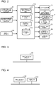
- FIG. 2 is a functional block diagram illustrating an example of the configuration of the controller 110 of FIG. 1 .
- the controller 110 includes a temperature acquisition unit 111, an arithmetic unit 112, a device control unit 113, and a storage unit 114.
- the controller 110 achieves various functions by executing software on an arithmetic device, such as a microcomputer, or is made of hardware, such as a circuit device, which achieves various functions.
- the temperature acquisition unit 111 is configured to acquire an outdoor air temperature detected by the outdoor air temperature sensor 15 and an evaporation temperature of the refrigerant in the heat receiving heat exchanger 9 for recovery detected by the evaporation temperature sensor 16.
- the arithmetic unit 112 is configured to perform arithmetic processing based on the outdoor air temperature and the evaporation temperature acquired by the temperature acquisition unit 111.
- the device control unit 113 is configured to control the compressor 11, the air expansion mechanism 12, the expansion mechanism 14 for recovery, the heat storage pump 21, the utilization pump 31, the flow switching device 32, and the terminal pump 41 based on the arithmetic result of the arithmetic unit 112. For example, the device control unit 113 controls the opening degrees of the air expansion mechanism 12 and the expansion mechanism 14 for recovery when heat recovery processing is performed by using residual heat of the terminal 1000 or heat of outdoor air.
- the storage unit 114 stores, in advance, various values that are used in the units of the controller 110.
- the storage unit 114 stores, in advance, a set value ⁇ that is set for a temperature to be used in arithmetic processing performed in the arithmetic unit 112.
- FIG. 3 is a hardware configuration diagram illustrating an example of the configuration of the controller 110 of FIG. 2 .
- the controller 110 of FIG. 2 is formed as a processing circuit 101 as shown in FIG. 3 .
- functions of the temperature acquisition unit 111, the arithmetic unit 112, the device control unit 113, and the storage unit 114 are achieved by the processing circuit 101.
- the processing circuit 101 corresponds to, for example, a single circuit, a composite circuit, a programmed processor, a parallel-programmed processor, an application specific integrated circuit (ASIC), a field-programmable gate array (FPGA), or a combination of those circuits.
- the controller 110 may achieve functions of the temperature acquisition unit 111, the arithmetic unit 112, the device control unit 113, and the storage unit 114 by using respective processing circuits 101 or by using a single processing circuit 101.
- FIG. 4 is a hardware configuration diagram illustrating another example of the configuration of the controller 110 of FIG. 2 .
- the controller 110 of FIG. 2 is formed as a processor 102 and a memory 103 as shown in FIG. 4 .
- functions of the temperature acquisition unit 111, the arithmetic unit 112, the device control unit 113, and the storage unit 114 are achieved by the processor 102 and the memory 103.
- the controller 110 achieves functions of the temperature acquisition unit 111, the arithmetic unit 112, the device control unit 113, and the storage unit 114 by using software, firmware, or a combination of software and firmware.
- the software or the firmware is described as a program, and is stored in the memory 103.
- the processor 102 achieves the functions of the above units by reading out and executing the program stored in the memory 103.
- a random access memory (RAM), a read only memory (ROM), a flash memory, an erasable and programmable ROM (EPROM), an electrically erasable and programmable ROM (EEPROM), or other types of non-volatile or volatile semiconductor memory is used, for example.
- a magnetic disc, a flexible disc, an optical disc, a compact disc (CD), a mini disc (MD), a digital versatile disc (DVD), or other types of removable recording medium may be used, for example.
- An input device 120 of FIG. 1 is operated by a user to input a usage state of the terminal 1000. For example, when the input device 120 is operated by a user, start and end of use of the terminal 1000 and other operations are set. The input device 120 transmits various kinds of set information to the controller 110.
- the heat storage material 7a housed in the heat storage tank 7 include a latent heat storage material that stores and releases heat by using latent heat associated with a phase change of the material, or a high-polymer heat storage material that stores and releases heat by using reaction heat generated when a high-polymer adsorbs and desorbs water molecules.
- a latent heat storage material is used as the heat storage material 7a.
- a latent heat storage material has a large heat storage amount per unit volume as compared with a sensible heat storage material, such as water that stores and releases heat by using sensible heat associated with a temperature change of the material. Therefore, by using a latent heat storage material as the heat storage material 7a, the filling amount of the heat storage material 7a can be reduced as compared to a case where a sensible heat storage material is used to store the same amount of heat.
- the heat recovery apparatus 100 can thus be made smaller.
- heat storage amount a case where the heat storage material 7a changes its temperature in a range of 40 °C to 55 °C will be examined.
- the latent heat of the paraffin per unit volume is about 208 kJ/L.
- the sensible heat of the paraffin per unit temperature change and per unit volume is 1.44 kJ/(L ⁇ K). Therefore, the heat storage amount of the paraffin per unit volume when the paraffin changes its temperature in a range of 40 °C to 55 °C is calculated by Equation 1.
- Heat storage amount 208 + 1.44 ⁇ 55 ⁇ 40 ⁇ 300 kJ / L
- the heat storage amount of the water per unit volume when the water changes its temperature in a range of 40 °C to 55 °C is calculated by Equation 2.
- Heat storage amount 4.2 ⁇ 55 ⁇ 40 ⁇ 63 kJ / L
- the heat storage amount of the latent heat storage material is about five times larger than that of the sensible heat storage material under the same condition. That is, when the latent heat storage material is used as the heat storage material 7a, the heat storage material 7a can store the same amount of heat with one fifth of the volume of the sensible heat storage material. Therefore, compared with a case where the sensible heat storage material is used as the heat storage material 7a, the heat storage tank 7 can be made smaller, and the heat recovery apparatus 100 can thus be made smaller.
- a heat storage operation a heat utilization operation, and a heat recovery operation are performed.
- the following describes flows of the refrigerant and the fluids during the heat storage operation, the heat utilization operation, and the heat recovery operation, and heat recovery processing during the heat recovery operation.
- Each of the operations described below is executed when the input device 120 is operated by a user.
- FIG. 5 is a schematic diagram for explaining the heat storage operation and the heat utilization operation of the heat recovery apparatus 100 of FIG. 1 .
- the heat storage operation is an operation that stores heat received from outdoor air in the heat storage material 7a.
- the heat utilization operation is an operation that supplies heat stored in the heat storage material 7a to the terminal 1000 from the heat storage material 7a when the terminal 1000 is used.
- the device control unit 113 When the heat storage operation is started, the device control unit 113 "opens” the air expansion mechanism 12 and “closes” the expansion mechanism 14 for recovery in the heat source unit 1 to cause the refrigerant to circulate in the air heat source circuit.
- the refrigerant flowing in the air heat source circuit in a low-temperature and low-pressure state is suctioned into the compressor 11, compressed by the compressor 11, and is then discharged from the compressor 11 in a high-temperature and high-pressure state.
- the refrigerant in a high-temperature and high-pressure state that has been discharged from the compressor 11 flows into the heat source heat exchanger 6.
- the refrigerant exchanges heat with the heat storage fluid flowing in the heat storage circuit, thereby rejecting heat, and then flows out from the heat source heat exchanger 6.
- the refrigerant that has flowed out from the heat source heat exchanger 6 is decompressed by the air expansion mechanism 12, and enters a low-temperature, low-pressure, and two-phase gas-liquid state.
- the refrigerant in a low-temperature, low-pressure, and two-phase gas-liquid state flows into the air heat receiving heat exchanger 13.
- the refrigerant exchanges heat with outdoor air suctioned by a fan, which is not shown, thereby receiving heat and evaporating, and then is suctioned into the compressor 11.
- the heat storage fluid flowing in the heat storage circuit is heated by using the heat received from the outdoor air.
- the device control unit 113 drives the heat storage pump 21.
- the heat storage fluid in the heat storage circuit is discharged from the heat storage pump 21 and flows into the heat source heat exchanger 6.
- the heat storage fluid that has flowed into the heat source heat exchanger 6 exchanges heat with the refrigerant flowing in the air heat source circuit, and then flows out from the heat source heat exchanger 6.
- the heat storage fluid that has flowed out from the heat source heat exchanger 6 flows into the heat storage heat exchanger 22, and exchanges heat with the heat storage material 7a in the heat storage tank 7, thereby rejecting heat. Then, the heat storage fluid that has rejected heat flows out from the heat storage heat exchanger 22.
- the heat storage fluid that has flowed out from the heat storage heat exchanger 22 is suctioned into the heat storage pump 21, pressurized by the heat storage pump 21, and is then discharged from the heat storage pump 21.
- the heat storage material 7a melts and changes its state from a solid to a liquid when the temperature of the heat storage material 7a increases by receiving heat in the heat storage heat exchanger 22 and reaches its melting point.
- the heat storage material 7a stores latent heat of fusion associated with the melting.
- the heat storage material 7a can store more heat as compared with a sensible heat storage material.
- the heat received from the outdoor air can be stored in the heat storage material 7a.
- the heat utilization operation will be described.
- the device control unit 113 drives the utilization pump 31 in the utilization unit 3.
- the device control unit 113 also switches the flow switching device 32 such that the utilization pump 31 and the utilization heat exchanger 33 communicate with each other.
- the utilization fluid in the utilization circuit is discharged from the utilization pump 31 and flows into the utilization heat exchanger 33.
- the utilization fluid that has flowed into the utilization heat exchanger 33 exchanges heat with the heat storage material 7a, and then flows out from the utilization heat exchanger 33.
- the utilization fluid that has flowed out from the utilization heat exchanger 33 flows into the terminal heat exchanger 8, and exchanges heat with the terminal fluid flowing in the terminal circuit, thereby rejecting heat. Then, the utilization fluid that has rejected heat flows out from the terminal heat exchanger 8.
- the utilization fluid that has flowed out from the terminal heat exchanger 8 is suctioned into the utilization pump 31, pressurized by the utilization pump 31, and is then discharged from the utilization pump 31.
- the device control unit 113 drives the terminal pump 41.
- the terminal fluid in the terminal circuit is discharged from the terminal pump 41, and flows into the terminal heat exchanger 8.
- the terminal fluid that has flowed into the terminal heat exchanger 8 exchanges heat with the utilization fluid flowing in the utilization circuit, thereby being heated, and then flows out from the terminal heat exchanger 8.
- the terminal fluid that has flowed out from the terminal heat exchanger 8 is supplied to the terminal 1000. After heat of the terminal fluid is used, the terminal fluid flows out from the terminal 1000. The terminal fluid that has flowed out from the terminal 1000 is suctioned into the terminal pump 41, pressurized by the terminal pump 41, and is then discharged from the terminal pump 41.
- the heat transferred from the heat storage material 7a can be used at the terminal 1000.
- a more specific example will be given for explaining the heat utilization operation.
- a case where a floor heating panel is used as the terminal 1000 is explained.
- the flow switching device 32 of the utilization unit 3 is switched such that the utilization pump 31 and the utilization heat exchanger 33 communicate with each other.
- the utilization pump 31 and the terminal pump 41 are in a driven state.
- the heat storage material 7a of the heat storage tank 7 rejects stored latent heat while solidifying at 50 °C, which is the melting point.
- the utilization fluid receives the heat from the heat storage material 7a at the utilization heat exchanger 33.
- the utilization fluid whose temperature has reached a temperature of 47 °C, for example, flows out from the utilization heat exchanger 33, and flows into the terminal heat exchanger 8.
- the terminal fluid rejects heat in the terminal 1000.
- the terminal fluid whose temperature has reached a temperature of 30 °C, for example, flows into the terminal heat exchanger 8. Then, in the terminal heat exchanger 8, the utilization fluid having a temperature of 47 °C and the terminal fluid having a temperature of 30 °C exchange heat with each other.
- the terminal fluid receives heat from the utilization fluid.
- the utilization fluid rejects heat to the terminal fluid.
- the temperature of fluid to be supplied to a floor heating panel be about 45 °C.
- the melting point of the heat storage material 7a is preferably about 50 °C.
- the terminal fluid whose temperature has reached a temperature of 30 °C, for example flows out from the terminal 1000, and then flows into the utilization heat exchanger 33.
- floor heating is used mainly during winter season, and the temperature of outdoor air in that period is about 7 °C, for example.
- FIG. 6 is a schematic diagram for explaining a heat recovery operation of the heat recovery apparatus 100 of FIG. 1 .
- the heat recovery operation is an operation that recovers residual heat of the terminal 1000 when use of the terminal 1000 is stopped.
- the device control unit 113 drives the terminal pump 41 in the terminal unit 4.
- the terminal fluid in the terminal circuit that has residual heat through use of the terminal 1000 is discharged from the terminal pump 41 and flows into the terminal heat exchanger 8.
- the terminal fluid that has flowed into the terminal heat exchanger 8 exchanges heat with the recovery fluid flowing in the recovery circuit, thereby rejecting heat, and then flows out from the terminal heat exchanger 8.
- the terminal fluid that has flowed out from the terminal heat exchanger 8 is supplied to the terminal 1000. After receiving the residual heat of the terminal 1000, the terminal fluid flows out from the terminal 1000. The terminal fluid that has flowed out from the terminal 1000 is suctioned into the terminal pump 41, pressurized by the terminal pump 41, and is then discharged from the terminal pump 41.
- the device control unit 113 drives the utilization pump 31 in the utilization unit 3 and the recovery unit 5.
- the device control unit 113 also switches the flow switching device 32 such that the utilization pump 31 and the heat receiving heat exchanger 9 for recovery communicate with each other.
- the recovery fluid in the recovery circuit is discharged from the utilization pump 31, and flows into the heat receiving heat exchanger 9 for recovery.
- the recovery fluid that has flowed into the heat receiving heat exchanger 9 for recovery exchanges heat with the refrigerant flowing in the recovery heat source circuit, thereby rejecting heat, and flows out from the heat receiving heat exchanger 9 for recovery.
- the recovery fluid that has flowed out from the heat receiving heat exchanger 9 for recovery flows into the terminal heat exchanger 8.
- the recovery fluid exchanges heat with the terminal fluid flowing in the terminal circuit, thereby being heated by the residual heat that the terminal fluid has.
- the heated recovery fluid then flows out from the terminal heat exchanger 8.
- the recovery fluid that has flowed out from the terminal heat exchanger 8 is suctioned into the utilization pump 31, pressurized by the utilization pump 31, and is then discharged from the utilization pump 31.
- the device control unit 113 "closes” the air expansion mechanism 12 and “opens” the expansion mechanism 14 for recovery in the heat source unit 1 to cause the refrigerant to circulate in the recovery heat source circuit.
- the refrigerant in a low-temperature and low-pressure state flowing in the recovery heat source circuit is suctioned into the compressor 11, compressed by the compressor 11, and is then discharged from the compressor 11 in a high-temperature and high-pressure state.
- the refrigerant in a high-temperature and high-pressure state that has been discharged from the compressor 11 flows into the heat source heat exchanger 6, exchanges heat with the heat storage fluid flowing in the heat storage circuit, and then flows out from the heat source heat exchanger 6.
- the refrigerant that has flowed out from the heat source heat exchanger 6 is decompressed by the expansion mechanism 14 for recovery, thereby entering a low-temperature, low-pressure, and two-phase gas-liquid state.
- the refrigerant in a low-temperature, low-pressure, and two-phase gas-liquid state flows into the heat receiving heat exchanger 9 for recovery, exchanges heat with the recovery fluid flowing in the recovery circuit, thereby receiving heat and evaporating, and then is suctioned into the compressor 11.
- the heat storage fluid is heated by using the heat received from the recovery fluid.
- the device control unit 113 drives the heat storage pump 21 in the heat storage unit 2.
- the heat storage fluid in the heat storage circuit is discharged from the heat storage pump 21, and flows into the heat source heat exchanger 6.
- the heat storage fluid that has flowed into the heat source heat exchanger 6 exchanges heat with the refrigerant flowing in the recovery heat source circuit, thereby being heated, and then flows out from the heat source heat exchanger 6.
- the heat storage fluid that has flowed out form the heat source heat exchanger 6 flows into the heat storage heat exchanger 22, and exchanges heat with the heat storage material 7a of the heat storage tank 7, thereby rejecting heat. Then, the heat storage fluid that has rejected heat flows out from the heat storage heat exchanger 22. Thus, heat of the heat storage fluid is stored in the heat storage material 7a.
- the heat storage fluid that has flowed out from the heat storage heat exchanger 22 is suctioned into the heat storage pump 21, pressurized by the heat storage pump 21, and is then discharged from the heat storage pump 21.
- a more specific example will be given for explaining the heat recovery operation.
- a case where a floor heating panel is used as the terminal 1000 is explained.
- the flow switching device 32 of the utilization unit 3 is switched such that the utilization pump 31 and the utilization heat exchanger 33 communicate with each other.
- the utilization pump 31 and the terminal pump 41 are in a driven state.
- the user operates the input device 120 such that an end instruction indicating an end of the use of the terminal 1000 is transmitted to the controller 110 from the input device 120.
- the device control unit 113 stops the utilization pump 31 and the terminal pump 41. Accordingly, the use of the terminal 1000 is ended.
- the device control unit 113 switches the flow switching device 32 such that the utilization pump 31 and the heat receiving heat exchanger 9 for recovery communicate with each other.
- the device control unit 113 also drives the utilization pump 31 and the terminal pump 41.
- the terminal fluid having a temperature of 35 °C circulates in the terminal circuit.
- the temperature of the recovery fluid is dropped to a temperature near an outdoor temperature. For example, when an outdoor temperature is 7 °C, the temperature of the recovery fluid is about 10 °C.
- the recovery fluid flows into the terminal heat exchanger 8 and exchanges heat with the terminal fluid, thereby receiving heat from the terminal fluid.
- the recovery fluid having a temperature of 30 °C, for example flows out from the terminal heat exchanger 8 and flows into the heat receiving heat exchanger 9 for recovery.
- the residual heat of the terminal 1000 is transferred to the heat receiving heat exchanger 9 for recovery.
- the device control unit 113 "opens" the expansion mechanism 14 for recovery and “closes” the air expansion mechanism 12 when the air expansion mechanism 12 is in an open state, and drives the compressor 11.
- the refrigerant in the heat source unit 1 circulates in the recovery heat source circuit.
- the refrigerant exchanges heat with the recovery fluid in the heat receiving heat exchanger 9 for recovery, thereby receiving heat from the recovery fluid and evaporating, and is then suctioned into the compressor 11.
- the device control unit 113 also drives the heat storage pump 21.
- the heat storage fluid circulates in the heat storage circuit.
- the heat storage fluid exchanges heat with the refrigerant in the heat source heat exchanger 6, thereby receiving heat from the refrigerant, and then flows into the heat storage heat exchanger 22.
- the heat storage fluid that has flowed into the heat storage heat exchanger 22 exchanges heat with the heat storage material 7a, thereby heating the heat storage material 7a, and then flows out from the heat storage heat exchanger 22.
- the residual heat of the terminal 1000 is recovered and stored in the heat storage tank 7, which houses the heat storage material 7a.
- the recovery fluid whose temperature has reached a temperature of 20 °C flows out from the heat receiving heat exchanger 9 for recovery and flows into the terminal heat exchanger 8.
- an evaporation temperature of the refrigerant be lower than the temperature of the liquid by about 2 °C.
- the recovery fluid has a temperature of 20 °C to 30 °C in the heat receiving heat exchanger 9 for recovery
- the evaporation temperature of the refrigerant is about 18 °C.
- an evaporation temperature of the refrigerant be lower than the temperature of the air by about 5 °C.
- the evaporation temperature is preferably 2 °C.
- the recovery fluid when used as a heat source, the evaporation temperature of the refrigerant is higher than that of a case where outdoor air having a temperature of 7 °C is used as a heat source.
- a power consumption of the compressor 11 generally becomes smaller as the evaporation temperature of refrigerant becomes higher, and the efficiency is thus improved.
- heat can be stored in the heat storage material 7a more efficiently as compared with a case where outdoor air is used as a heat source.
- the temperature of the terminal fluid is lowered as the temperature of the residual heat of the terminal 1000 is lowered. Accordingly, the temperature of the recovery fluid is lowered. As a result, the evaporation temperature of the refrigerant in the heat receiving heat exchanger 9 for recovery is lowered as recovery of heat progresses. Meanwhile, because it is preferable that a temperature difference between the recovery fluid and the refrigerant in the heat receiving heat exchanger 9 for recovery be about 2 °C, when the temperature of the recovery fluid flowing out from the heat receiving heat exchanger 9 for recovery is lowered to 4 °C, for example, the evaporation temperature of the refrigerant is 2 °C.
- the evaporation temperature is further lowered, and thus the heat storage efficiency is degraded.
- the evaporation temperature can be kept at 2 °C, and thus lowering of the evaporation temperature can be avoided. This is because outdoor air has an enormous heat capacity and the temperature of outdoor air is not lowered even when heat is removed from the outdoor air. Therefore, the evaporation temperature is not lowered.
- the evaporation temperature of the refrigerant when the evaporation temperature of the refrigerant is lowered as the temperature of the recovery fluid is lowered, the evaporation temperature of the refrigerant can be kept higher in a case where heat is received from the recovery fluid, as compared with a case where heat is received from outdoor air, while the evaporation temperature is greater than a value obtained by subtracting the set value ⁇ from the outdoor air temperature (evaporation temperature > outdoor air temperature - ⁇ , where the set value ⁇ is 5 °C, for example). Accordingly, the efficiency is improved.
- the evaporation temperature of the refrigerant can be kept higher in a case where heat is received from outdoor air, as compared with a case where heat is received from the recovery fluid, while the evaporation temperature is less than or equal to a value obtained by subtracting the set value ⁇ from the outdoor air temperature (evaporation temperature ⁇ outdoor air temperature - ⁇ ). Accordingly, the efficiency is improved.
- the temperature acquisition unit 111 acquires the evaporation temperature of the refrigerant and the temperature of outdoor air.
- evaporation temperature > outdoor air temperature - ⁇ is determined by the arithmetic unit 112
- acquisition of the evaporation temperature of the refrigerant and the temperature of outdoor air is continued while recovery of heat from the terminal fluid is continued.
- evaporation temperature ⁇ outdoor air temperature - ⁇ is determined, the device control unit 113 "opens" the air expansion mechanism 12 and "closes” the expansion mechanism 14 for recovery.
- the recovery heat source circuit is blocked, and the refrigerant is caused to circulate in the air heat source circuit, instead of the recovery heat source circuit.
- the refrigerant circulating in the air heat source circuit receives heat from the outdoor air having a temperature of 7 °C.
- the heat recovery apparatus 100 when the heat recovery apparatus 100 is installed, the heat recovery apparatus 100 is connected to the terminal 1000. At the time of connection, foreign substances such as dust associated with the connection operation may enter the terminal circuit. However, because the recovery pipe 50 of the recovery circuit, which recovers the residual heat of the terminal 1000, is not connected to the terminal pipe 40 of the terminal circuit, foreign substances in the terminal circuit never enters the recovery circuit and thus never blocks the recovery circuit.
- the terminal circuit and the recovery circuit are provided separately in the heat recovery apparatus 100 and the recovery fluid in the recovery pipe 50 can flow appropriately, the residual heat of the terminal 1000 can be transferred to the recovery heat source circuit in a reliable manner.
- FIG. 7 is a flowchart illustrating an example of a flow of heat recovery processing of the heat recovery apparatus 100 according to Embodiment 1.
- step S1 when an end instruction indicating an end of use of the terminal 1000 is transmitted from the input device 120, the device control unit 113 of the controller 110 stops driving of the utilization pump 31 and the terminal pump 41 in step S2.
- step S3 the device control unit 113 switches the flow switching device 32 such that the utilization pump 31 and the heat receiving heat exchanger 9 for recovery communicate with each other.
- step S4 the device control unit 113 drives the utilization pump 31 and the terminal pump 41.
- the terminal fluid circulates in the terminal circuit and the recovery fluid circulates in the recovery circuit.
- the device control unit 113 "closes" the air expansion mechanism 12 in step S5 when the air expansion mechanism 12 is in an open state, and "opens” the expansion mechanism 14 for recovery in step S6.
- the device control unit 113 drives the compressor 11 in step S7, and drives the heat storage pump 21 in step S8.
- the refrigerant circulates in the recovery heat source circuit and the heat storage fluid circulates in the heat storage circuit.
- the heat recovery operation for recovering the residual heat of the terminal 1000 is started.
- step S9 the arithmetic unit 112 determines whether or not "evaporation temperature ⁇ outdoor air temperature - ⁇ " is satisfied based on the outdoor air temperature detected by the outdoor air temperature sensor 15 and the evaporation temperature of the refrigerant in the heat receiving heat exchanger 9 for recovery detected by the evaporation temperature sensor 16.
- step S9 When the determination result indicates that "evaporation temperature ⁇ outdoor air temperature - ⁇ " is satisfied (YES in step S9), the process proceeds to step S10. Meanwhile, when “evaporation temperature > outdoor air temperature - ⁇ " is satisfied (NO in step S9), the process of step S9 is repeated until the condition of "evaporation temperature ⁇ outdoor air temperature - ⁇ " is obtained.
- step S10 the device control unit 113 "opens” the air expansion mechanism 12.
- step S11 the device control unit 113 "closes” the expansion mechanism 14 for recovery.
- the refrigerant circulates in the air heat source circuit and the heat recovery operation is performed by using heat of outdoor air.
- the heat recovery processing is performed to recover the residual heat of the terminal 1000.
- residual heat to be recovered includes residual heat in the terminal pipe 40.
- the heat storage material 7a As described above, in the heat recovery apparatus 100 according to Embodiment 1, at least a latent heat storage material or a high-polymer heat storage material is used as the heat storage material 7a, which is filled in the heat storage tank 7 and stores heat.
- the heat storage material 7a can store the same amount of heat with less filling amount, as compared with some heat storage material such as a sensible heat storage material, the heat storage tank 7 that houses the heat storage material 7a can be made smaller, and the entire heat recovery apparatus 100 can thus be made smaller.
- the heat recovery apparatus 100 includes the utilization circuit, in which the utilization heat exchanger 33, the terminal heat exchanger 8, and the utilization pump 31 are connected by the utilization pipe 30 and the utilization fluid circulates, and the recovery circuit, which includes a part of the utilization pipe 30 and the recovery pipe 50 connecting between a point between the utilization heat exchanger 33 and the utilization pump 31 and a point between the utilization heat exchanger 33 and the terminal heat exchanger 8, and in which the recovery fluid circulates.
- the utilization circuit in which the utilization heat exchanger 33, the terminal heat exchanger 8, and the utilization pump 31 are connected by the utilization pipe 30 and the utilization fluid circulates
- the recovery circuit which includes a part of the utilization pipe 30 and the recovery pipe 50 connecting between a point between the utilization heat exchanger 33 and the utilization pump 31 and a point between the utilization heat exchanger 33 and the terminal heat exchanger 8, and in which the recovery fluid circulates.
- the flow switching device 32 is further provided either at a point between the utilization heat exchanger 33 and the utilization pump 31 or a point between the utilization heat exchanger 33 and the terminal heat exchanger 8.
- the flow switching device 32 switches flow paths such that the utilization pump 31 and the utilization heat exchanger 33 communicate with each other when the utilization fluid is caused to flow in the utilization circuit, and such that the utilization pump 31 and the heat receiving heat exchanger 9 for recovery communicate with each other when the recovery fluid is caused to flow in the recovery circuit.
- the utilization fluid and the recovery fluid is the same fluid. With this configuration, because a part of the utilization circuit is used as the recovery circuit, the entire heat recovery apparatus 100 can be made smaller.
- the flow switching device 32 switches flow paths such that the utilization pump 31 and the heat receiving heat exchanger 9 for recovery communicate with each other when use of the terminal 1000 is ended.
- the residual heat of the terminal 1000 is transferred to the heat receiving heat exchanger 9 for recovery via the recovery circuit, and the residual heat can thus be recovered through the recovery heat source circuit.
- the terminal circuit is provided with the terminal pipe 40 connecting the terminal pump 41, the terminal heat exchanger 8, and the terminal 1000, which is provided outside the heat recovery apparatus 100. Because the recovery pipe 50 of the recovery circuit, which recovers the residual heat of the terminal 1000, is not connected to the terminal pipe 40 of the terminal circuit, foreign substances in the terminal circuit never enters the recovery circuit and thus never blocks the recovery circuit. Therefore, in the heat recovery apparatus 100, because the recovery fluid in the recovery pipe 50 can flow appropriately, the residual heat of the terminal 1000 can be transferred to the recovery heat source circuit in a reliable manner.
- the heat receiving heat exchanger 9 for recovery causes the recovery fluid to reject heat to the refrigerant that has flowed out from the expansion mechanism 14 for recovery. Therefore, the heat storage fluid can be heated by using the heat received from the recovery fluid, and thus the recovered heat can be stored appropriately.
- the air heat source circuit further includes the air expansion mechanism 12, which is configured to expand the refrigerant that has flowed out from the heat source heat exchanger 6, and the air heat receiving heat exchanger 13, which is configured to exchange heat between the refrigerant that has flowed out from the air expansion mechanism 12 and outdoor air and cause the refrigerant to receive heat from the outdoor air. Therefore, heat can be received also from outdoor air, and thus the efficiency of heat storage can be improved.
- the expansion mechanism 14 for recovery when use of the terminal 1000 is ended, the expansion mechanism 14 for recovery is opened, and, when the air expansion mechanism 12 is in an open state, the air expansion mechanism 12 is closed. Furthermore, when the evaporation temperature of the refrigerant detected by the evaporation temperature sensor 16 is lower than a value that is obtained by subtracting the set temperature ⁇ from the outdoor air temperature detected by the outdoor air temperature sensor 15, the heat recovery apparatus 100 closes the expansion mechanism 14 for recovery and opens the air expansion mechanism 12. Therefore, lowering of the evaporation temperature can be avoided, and thus the efficiency of heat storage can be improved.
- Embodiment 2 of the present invention will be described below.
- Embodiment 2 differs from Embodiment 1 in that a hot water supply unit and a hot wastewater unit are provided. Note that, in Embodiment 2, components that are the same as those of Embodiment 1 will be denoted by the same reference signs, and their descriptions will be omitted.
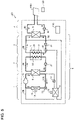
- FIG. 8 is a circuit diagram illustrating an example of the configuration of a heat recovery apparatus 200 according to Embodiment 2.
- the heat recovery apparatus 200 mainly includes a heat source unit 1, a heat storage unit 2, a utilization unit 3, a terminal unit 4, a recovery unit 5, a hot water supply unit 206, a hot wastewater unit 207, and a controller 110.
- a terminal 1001 to be used by a user, a hot water supply terminal 1002 to be used by a user, and a hot wastewater tank 1003 are connected to the heat recovery apparatus 200.
- the terminal 1001 is a bathtub, for example.
- the heat recovery apparatus 200 is used to heat the hot water in the bathtub for reheating and to keep the hot water hot.
- the terminal 1001 is not limited to a bathtub, and may be, for example, the floor heating panel described in Embodiment 1.
- the hot water supply terminal 1002 is, for example, a shower, and hot water is supplied to the hot water supply terminal 1002 from the heat recovery apparatus 200.
- the hot water supply terminal 1002 is not limited to a shower, and may be one of various terminals that supply hot water for, for example, washing faces, washing hands, washing dishes, and other purposes.
- the hot wastewater tank 1003 is a hot water storage tank that stores hot water used by a user through the hot water supply terminal 1002. That is, the hot wastewater tank 1003 stores fluid having residual heat after use.
- the hot wastewater tank 1003 may be connected to the terminal 1001 such that the hot water of the terminal 1001, which is a bathtub, enters the hot wastewater tank 1003.
- the hot water supply unit 206 includes a water supply end 61 and a hot water supply heat exchanger 62.
- the hot water supply unit 206 is provided with a water supply pipe 60A connecting the water supply end 61 and the hot water supply heat exchanger 62, and a hot water supply pipe 60B connecting the hot water supply heat exchanger 62 and the hot water supply terminal 1002.
- the water supply end 61 and the hot water supply heat exchanger 62 are connected by the water supply pipe 60A and the hot water supply pipe 60B to form a hot water supply circuit.
- a water pipe, a well water pipe, a clean water pipe, or a city water pipe is connected to the water supply end 61, and tap water or other water is supplied to the water supply end 61.
- the hot water supply heat exchanger 62 is housed in the heat storage tank 7. In the hot water supply heat exchanger 62, heat exchange is performed between the tap water supplied via the water supply end 61 and the heat storage material 7a filled in the heat storage tank 7. In the hot water supply heat exchanger 62 of Embodiment 2, by rejecting heat stored in the heat storage material 7a to the tap water, the tap water is heated and thus becomes hot water. The generated hot water flows out from the hot water supply heat exchanger 62 and is supplied to the hot water supply terminal 1002 via the hot water supply pipe 60B.
- the hot wastewater unit 207 includes a first hot wastewater flow switching device 71, a second hot wastewater flow switching device 72, a terminal pump 41, and a terminal heat exchanger 8.
- a hot wastewater circuit, through which hot wastewater circulates, is formed by sequentially connecting the first hot wastewater flow switching device 71, the terminal pump 41, the terminal heat exchanger 8, the second hot wastewater flow switching device 72, and the hot wastewater tank 1003 by a part of the terminal pipe 40, a first hot wastewater pipe 70A, and a second hot wastewater pipe 70B.
- One end of the first hot wastewater pipe 70A is connected to the hot wastewater tank 1003, and the other end of the first hot wastewater pipe 70A is connected to the first hot wastewater flow switching device 71.
- One end of the second hot wastewater pipe 70B is connected to the hot wastewater tank 1003, and the other end of the second hot wastewater pipe 70B is connected to the second hot wastewater flow switching device 72.
- the first hot wastewater flow switching device 71 is, for example, a three-way valve, and is configured to switch flow directions of fluid by making flow paths in two directions, out of three directions, communicate with each other while blocking a flow path of the remaining one direction.
- the first hot wastewater flow switching device 71 is installed on the terminal circuit between the terminal 1001 and the terminal pump 41. When residual heat of the hot wastewater tank 1003 is recovered, the first hot wastewater flow switching device 71 is switched as shown by the broken line of FIG. 8 , so that the hot wastewater tank 1003 and the terminal pump 41 communicate with each other. Switching of the flow paths in the first hot wastewater flow switching device 71 is controlled by the controller 110.
- the second hot wastewater flow switching device 72 is, for example, a three-way valve, and is configured to switch flow directions of fluid by making flow paths in two directions, out of three directions, communicate with each other while blocking a flow path of the remaining one direction.
- the second hot wastewater flow switching device 72 is installed on the terminal circuit between the terminal 1001 and the terminal heat exchanger 8.
- the second hot wastewater flow switching device 72 is switched as shown by the broken line of FIG. 8 , so that the hot wastewater tank 1003 and the terminal heat exchanger 8 communicate with each other. Switching of the flow paths in the second hot wastewater flow switching device 72 is controlled by the controller 110.
- the controller 110 has the same configuration as that of Embodiment 1. However, in Embodiment 2, the controller 110 controls the first hot wastewater flow switching device 71 and the second hot wastewater flow switching device 72, in addition to the compressor 11, the air expansion mechanism 12, the expansion mechanism 14 for recovery, the heat storage pump 21, the utilization pump 31, the flow switching device 32, and the terminal pump 41.
- Embodiment 2 a heat storage operation, a heat utilization operation, and a heat recovery operation are performed, as with Embodiment 1.
- Embodiment 2 residual heat of the hot wastewater tank 1003 as well as residual heat of the terminal 1001 are recovered.
- the heat storage material 7a of the heat storage tank 7 rejects stored latent heat while solidifying at 50 °C, which is the melting point.
- the utilization fluid receives heat from the heat storage material 7a at the utilization heat exchanger 33.
- the utilization fluid whose temperature has reached a temperature of 47 °C, for example, flows out from the utilization heat exchanger 33 and flows into the terminal heat exchanger 8.
- the terminal fluid is mixed with the hot water of the terminal 1001 in the terminal 1001 and the temperature of the terminal fluid is reduced.
- the terminal fluid receives heat from the utilization fluid.
- the temperature of hot water is about 40 °C to 45 °C.
- the melting point of the heat storage material 7a is preferably about 50 °C.
- the temperature of outdoor air is about 7 °C, for example.
- tap water that has flowed into the hot water supply heat exchanger 62 via the water supply pipe 60A exchanges heat with the heat storage material 7a, thereby being heated, and flows out from the hot water supply heat exchanger 62 as hot water.
- the hot water that has flowed out from the hot water supply heat exchanger 62 is supplied to the hot water supply terminal 1002 via the hot water supply pipe 60B and is used by the user.
- the heat storage material 7a of the heat storage tank 7 rejects stored latent heat while solidifying at 50 °C, which is the melting point.
- the tap water receives heat from the heat storage material 7a at the hot water supply heat exchanger 62.
- the temperature of the hot water is about 40 °C to 45 °C.
- the melting point of the heat storage material 7a is preferably about 50 °C.
- FIG. 9 is a flowchart illustrating an example of a flow of heat recovery processing of the heat recovery apparatus 200 according to Embodiment 2.
- the heat recovery operation will be explained with reference to the flowchart of FIG. 9 by using a more specific example.
- a case where a bathtub is used as the terminal 1001 will be explained.
- the user When use of the terminal 1001 is ended because the user finishes taking a bath or for other reasons, the user operates the input device 120 such that an end instruction indicating an end of use of the terminal 1001 is transmitted to the controller 110 from the input device 120 in step S1.
- the controller 110 stops the utilization pump 31 and the terminal pump 41 in step S2. Accordingly, the use of the terminal 1001 is ended.
- hot wastewater after shower is stored in the hot wastewater tank 1003. Because, in general, the temperature of hot water used in shower is about 40 °C to 45 °C, the temperature of hot wastewater after shower is 35 °C, for example.
- the device control unit 113 switches the flow switching device 32 such that the utilization pump 31 and the heat receiving heat exchanger 9 for recovery communicate with each other in step S3.
- the device control unit 113 also drives the utilization pump 31 and the terminal pump 41 in step S4.
- the terminal fluid having a temperature of 42 °C circulates in the terminal circuit.
- the recovery fluid in the recovery circuit flows into the terminal heat exchanger 8 and exchanges heat with the terminal fluid, thereby receiving heat from the terminal fluid. Then, the recovery fluid whose temperature has reached a temperature of 37 °C, for example, flows out from the terminal heat exchanger 8 and flows into the heat receiving heat exchanger 9 for recovery. In this process, the residual heat of the terminal 1001 is transferred to the heat receiving heat exchanger 9 for recovery.
- the device control unit 113 "closes” the air expansion mechanism 12 in step S5 when the air expansion mechanism 12 is in an open state, and "opens" the expansion mechanism 14 for recovery in step S6.
- the device control unit 113 drives the compressor 11.
- the refrigerant in the heat source unit 1 circulates in the recovery heat source circuit.
- the refrigerant exchanges heat with the recovery fluid in the heat receiving heat exchanger 9 for recovery, thereby receiving heat from the recovery fluid and evaporating, and is then suctioned into the compressor 11.
- the device control unit 113 also drives the heat storage pump 21 in step S8.
- the heat storage fluid circulates in the heat storage circuit.
- the heat storage fluid exchanges heat with the refrigerant in the heat source heat exchanger 6, thereby receiving heat from the refrigerant, and then flows into the heat storage heat exchanger 22.
- the heat storage fluid that has flowed into the heat storage heat exchanger 22 exchanges heat with the heat storage material 7a, thereby heating the heat storage material 7a, and then flows out from the heat storage heat exchanger 22.
- the residual heat of the terminal 1001 is recovered and stored in the heat storage tank 7, which houses the heat storage material 7a.
- the recovery fluid having a temperature of 25 °C flows out from the heat receiving heat exchanger 9 for recovery and flows into the terminal heat exchanger 8.
- an evaporation temperature of the refrigerant be lower than the temperature of the liquid by about 2 °C.
- the evaporation temperature of the refrigerant is about 23 °C.
- an evaporation temperature of the refrigerant be lower than the temperature of the air by about 5 °C.
- the evaporation temperature is preferably 2 °C.
- the recovery fluid when used as a heat source, the evaporation temperature of the refrigerant is higher than that of a case where outdoor air having a temperature of 7 °C is used as a heat source.
- a power consumption of the compressor 11 generally becomes smaller as the evaporation temperature of the refrigerant becomes higher, and the efficiency is thus improved.
- heat can be stored in the heat storage material 7a more efficiently as compared with a case where outdoor air is used as a heat source.
- the temperature of the terminal fluid is lowered as the temperature of the residual heat of the terminal 1001 is lowered. Accordingly, the temperature of the recovery fluid is lowered. As a result, the evaporation temperature of the refrigerant in the heat receiving heat exchanger 9 for recovery is lowered as recovery of heat progresses. Meanwhile, because it is preferable that a temperature difference between the recovery fluid and the refrigerant in the heat receiving heat exchanger 9 for recovery be about 2 °C, when the temperature of the recovery fluid flowing out from the heat receiving heat exchanger 9 for recovery is lowered to 4 °C, for example, the evaporation temperature of the refrigerant is 2 °C.
- Embodiment 2 when the evaporation temperature is less than or equal to a value obtained by subtracting the set value ⁇ from the outdoor air temperature (evaporation temperature ⁇ outdoor air temperature - ⁇ ), recovery processing of the residual heat of the hot wastewater tank 1003 is performed.
- step S29 the arithmetic unit 112 determines whether or not "evaporation temperature ⁇ outdoor air temperature - ⁇ " is satisfied based on the outdoor air temperature detected by the outdoor air temperature sensor 15 and the evaporation temperature of the refrigerant in the heat receiving heat exchanger 9 for recovery detected by the evaporation temperature sensor 16.
- step S29 When the determination result indicates that "evaporation temperature ⁇ outdoor air temperature - ⁇ " is satisfied (YES in step S29), the process proceeds to step S30. Meanwhile, when “evaporation temperature > outdoor air temperature - ⁇ " is satisfied (NO in step S29), the process of step S29 is repeated until the condition of "evaporation temperature ⁇ outdoor air temperature - ⁇ " is obtained.
- step S30 the device control unit 113 switches the first hot wastewater flow switching device 71 such that the hot wastewater tank 1003 and the terminal pump 41 communicate with each other.
- step S31 the device control unit 113 switches the second hot wastewater flow switching device 72 such that the hot wastewater tank 1003 and the terminal heat exchanger 8 communicate with each other.
- hot wastewater having residual heat of the hot wastewater tank 1003 circulates in the hot wastewater circuit, and the heat recovery apparatus 200 can recover the residual heat of the hot wastewater after recovering the residual heat of the terminal 1001.
- the processing of step S30 and the processing of step S31 may be performed in reverse order or may be performed simultaneously.
- the heat recovery apparatus 200 can store heat in the heat storage material 7a with an improved efficiency.
- the temperature of the hot wastewater circulating in the hot wastewater circuit is lowered as the temperature of the residual heat of the hot wastewater tank 1003 is lowered. Accordingly, the temperature of the recovery fluid is lowered. As a result, the evaporation temperature of the refrigerant in the heat receiving heat exchanger 9 for recovery is lowered as recovery of heat progresses. Meanwhile, because it is preferable that a temperature difference between the recovery fluid and the refrigerant in the heat receiving heat exchanger 9 for recovery be about 2 °C, when the temperature of the recovery fluid flowing out from the heat receiving heat exchanger 9 for recovery is lowered to 4 °C, for example, the evaporation temperature of the refrigerant is 2 °C.
- Embodiment 1 when the recovery of heat from the residual heat of the hot wastewater tank 1003 is continued, the evaporation temperature is further lowered, and thus the heat storage efficiency is degraded. At this time, when heat is received from outdoor air having a temperature of 7 °C, for example, the evaporation temperature can be kept at 2 °C, and thus lowering of the evaporation temperature can be avoided. This is because outdoor air has an enormous heat capacity and the temperature of the outdoor air is not lowered even when heat is removed from the outdoor air. Therefore, the evaporation temperature is not lowered.
- step S32 the arithmetic unit 112 determines whether or not "evaporation temperature ⁇ outdoor air temperature - ⁇ " is satisfied based on the outdoor air temperature detected by the outdoor air temperature sensor 15 and the evaporation temperature of the refrigerant in the heat receiving heat exchanger 9 for recovery detected by the evaporation temperature sensor 16.
- step S32 When the determination result indicates that "evaporation temperature ⁇ outdoor air temperature - ⁇ " is satisfied (YES in step S32), the process proceeds to step S33. Meanwhile, when “evaporation temperature > outdoor air temperature - ⁇ " is satisfied (NO in step S32), the process of step S32 is repeated until the condition of "evaporation temperature ⁇ outdoor air temperature - ⁇ " is obtained.
- step S33 the device control unit 113 "opens" the air expansion mechanism 12.
- step S34 the device control unit 113 "closes" the expansion mechanism 14 for recovery. As a result, the recovery heat source circuit is blocked, and the refrigerant is caused to circulate in the air heat source circuit. In this manner, the heat recovery operation using heat of outdoor air is performed.
- the heat recovery apparatus 200 further includes the hot water supply heat exchanger 62 housed in the heat storage tank 7, and the hot water supply terminal 1002, to which tap water that has flowed from the hot water supply heat exchanger 62 is supplied via the hot water supply pipe 60B.
- the hot water tank or a similar device that stores hot water to be supplied to the hot water supply terminal 1002 is not required, and thus the heat recovery apparatus 200 can be made smaller.
- the heat recovery apparatus 200 further includes the hot wastewater tank 1003 and the hot wastewater circuit, which is formed by including the first hot wastewater pipe 70A, the second hot wastewater pipe 70B, and a part of the terminal pipe 40.
- the hot wastewater circuit is further provided with the first hot wastewater flow switching device 71 and the second hot wastewater flow switching device 72.
- the expansion mechanism 14 for recovery is opened, and the air expansion mechanism 12 is closed when the air expansion mechanism 12 is in an open state. Furthermore, when the evaporation temperature is less than a value obtained by subtracting the set temperature ⁇ from the outdoor air temperature, the first hot wastewater flow switching device 71 is switched such that the hot wastewater tank 1003 and the terminal pump 41 communicate with each other, and the second hot wastewater flow switching device 72 is switched such that the hot wastewater tank 1003 and the terminal heat exchanger 8 communicate with each other. Therefore, after the residual heat of the terminal 1001 is recovered, the residual heat of the hot wastewater is further recovered. Thus, the residual heat can be recovered efficiently.
- the expansion mechanism 14 for recovery when the evaporation temperature is less than a value obtained by subtracting the set temperature ⁇ from the outdoor air temperature, the expansion mechanism 14 for recovery is closed and the air expansion mechanism 12 is opened. Therefore, because heat of outdoor air can be received in addition to the residual heat of the terminal 1001 and the residual heat of the hot wastewater, the heat storage efficiency can be further improved.
- the heat recovery apparatus of each of Embodiments 1 and 2 has been explained above, the heat recovery apparatus is not limited to those of Embodiments 1 and 2 described above. Various modifications and applications are feasible without departing from the scope of the gist.
- the heat storage fluid, the utilization fluid, the recovery fluid, and the terminal fluid at least two or more of the fluids may be the same type of fluid, or all of the fluids may be of different types. For example, when all of the fluids are the same type of fluid, the cost can be reduced.
- the heat recovery processing is started in accordance with the instruction indicating an end of use of the terminal 1000 or the terminal 1001.
- the method for starting the processing is not limited to the method.
- the heat recovery processing may be started in accordance with an instruction for starting the heat recovery processing. That is, any method can be used as long as the user can instruct the heat recovery apparatus to start the heat recovery processing when use of the terminal 1000 or the terminal 1001 is ended
Landscapes
- Engineering & Computer Science (AREA)
- Physics & Mathematics (AREA)
- Thermal Sciences (AREA)
- Chemical & Material Sciences (AREA)
- Combustion & Propulsion (AREA)
- Mechanical Engineering (AREA)
- General Engineering & Computer Science (AREA)
- Heat-Pump Type And Storage Water Heaters (AREA)
- Central Heating Systems (AREA)
Abstract
Description
- The present invention relates to a heat recovery apparatus that recovers heat from a terminal that utilizes heat.
- Various heat recovery apparatuses have been proposed for recovering residual heat of heating or other operation. For example, Patent Literature 1 discloses a heat recovery apparatus that recovers heat from a remaining hot water in a bathtub with an improved efficiency. The heat recovery apparatus described in Patent Literature 1 includes a hot water storage tank for storing, as hot water, heat that is used when a user takes a shower or fills the bathtub with hot water, and a heat storage material for recovering residual heat of the bathtub. The heat recovery apparatus recovers residual heat of the bathtub by using latent heat of the heat storage material.
- Patent Literature 1:
Japanese Unexamined Patent Application Publication JP 2010-7935 A - However, in a general home, supply of hot water for shower and washing faces, hands and dishes is required for the number of family members, and supply of hot water for filling a bathtub is also required. In this case, a heat storage amount of about 60 to 70 mega-joules (MJ) is required during winter season. Meanwhile, a heat amount that can be recovered from a bathtub is about 10 MJ, and this amount is about one sixth to seventh of the required heat storage amount.
- In general, when heat is stored by using latent heat of a heat storage material, the thermal capacity per volume is large, compared with a case where heat is stored by hot water (that is, a case of sensible heat storage). Therefore, when the same amount of heat is stored, a smaller volume is required in latent heat storage utilizing latent heat of a heat storage material, compared with a case of sensible heat storage utilizing hot water.
- However, because the heat recovery apparatus described in Patent Literature 1 uses a heat storage material utilizing latent heat for recovering heat from a bathtub, that is, for storing a heat of 10 MJ, a large heat storage tank is required for supplying hot water for a heat amount of 70 MJ. Consequently, it is difficult to reduce the size of the entire apparatus.
- The present invention has been made to solve the problem described above, and has an object to provide a heat recovery apparatus with a reduced size.
- A heat recovery apparatus according to an embodiment of the present invention is configured to recover residual heat of a terminal that is connected to the heat recovery apparatus and utilizes heat. The heat recovery apparatus includes a terminal circuit to which the terminal is connected and configured to supply heat to the terminal by allowing terminal fluid to circulate in the terminal circuit, a recovery circuit in which recovery fluid circulates and configured to recover residual heat of the terminal, a heat source circuit in which refrigerant circulates and configured to generate heat by using heat recovered in the recovery circuit, a heat storage circuit in which heat storage fluid circulates and configured to reject the heat generated in the heat source circuit to a heat storage material, and a heat storage tank that houses the heat storage material. The heat storage material includes at least a latent heat storage material or a high-polymer heat storage material.
- As described above, in the heat recovery apparatus according to an embodiment of the present invention, a latent heat storage material or a high-polymer heat storage material is used as the heat storage material for storing heat. As a result, the heat storage tank storing the heat storage material can be made smaller, and the entire apparatus thus can be made smaller.
-
- FIG. 1
- is a circuit diagram illustrating an example of the configuration of a heat recovery apparatus according to Embodiment 1.
- FIG. 2
- is a functional block diagram illustrating an example of the configuration of a controller of
FIG. 1 . - FIG. 3
- is a hardware configuration diagram illustrating an example of the configuration of a controller of
FIG. 2 . - FIG. 4
- is a hardware configuration diagram illustrating another example of the configuration of the controller of
FIG. 2 . - FIG. 5
- is a schematic diagram for explaining a heat storage operation and a heat utilization operation of the heat recovery apparatus of
FIG. 1 . - FIG. 6
- is a schematic diagram for explaining a heat recovery operation of the heat recovery apparatus of
FIG. 1 . - FIG. 7
- is a flowchart illustrating an example of a flow of heat recovery processing of the heat recovery apparatus according to Embodiment 1.
- FIG. 8
- is a circuit diagram illustrating an example of the configuration of a heat recovery apparatus according to
Embodiment 2. - FIG. 9
- is a flowchart illustrating an example of a flow of heat recovery processing of the heat recovery apparatus according to
Embodiment 2. - A heat recovery apparatus according to Embodiment 1 will be described below. The heat recovery apparatus according to Embodiment 1 is configured to store heat from a heat source and enable a terminal connected to the heat recovery apparatus to utilize the stored heat.
-
FIG. 1 is a circuit diagram illustrating an example of the configuration of aheat recovery apparatus 100 according to Embodiment 1. As shown inFIG. 1 , theheat recovery apparatus 100 mainly includes a heat source unit 1, aheat storage unit 2, autilization unit 3, aterminal unit 4, arecovery unit 5, and acontroller 110. Aterminal 1000 to be used by a user is connected to theheat recovery apparatus 100. Theterminal 1000 utilizes heat stored in theheat recovery apparatus 100 to perform heating or other operation. Theterminal 1000 is a floor heating panel, for example, but is not limited to a floor heating panel. Theterminal 1000 may be a panel heater or a heating radiator, for example. In addition, theterminal 1000 may be a bathtub. In this case, theheat recovery apparatus 100 is used to heat hot water in the bathtub for reheating and to keep the hot water hot. - The heat source unit 1 includes a
compressor 11, a heat source heat exchanger 6, anair expansion mechanism 12, an air heat receivingheat exchanger 13, anexpansion mechanism 14 for recovery, and a heat receivingheat exchanger 9 for recovery. The heat source unit 1 is provided with an airheat source pipe 10A to which thecompressor 11, the heat source heat exchanger 6, theair expansion mechanism 12, and the air heat receivingheat exchanger 13 are connected. An air heat source circuit, through which refrigerant circulates, is formed by sequentially connecting thecompressor 11, the heat source heat exchanger 6, theair expansion mechanism 12, and the air heat receivingheat exchanger 13 by the airheat source pipe 10A. - Furthermore, the heat source unit 1 is provided with a recovery
heat source pipe 10B, which branches off at a point between a refrigerant outflow side of the heat source heat exchanger 6 and a refrigerant inflow side of theair expansion mechanism 12 and joins at a point between a refrigerant outflow side of the air heat receivingheat exchanger 13 and a suction side of thecompressor 11. Anexpansion mechanism 14 for recovery and a heat receivingheat exchanger 9 for recovery are connected to the recoveryheat source pipe 10B. A recovery heat source circuit, through which refrigerant circulates, is formed by sequentially connecting thecompressor 11, the heat source heat exchanger 6, theexpansion mechanism 14 for recovery, and the heat receivingheat exchanger 9 for recovery by the recoveryheat source pipe 10B and a part of the airheat source pipe 10A. - As refrigerant circulating in the air heat source circuit and the recovery heat source circuit, a hydrofluorocarbon (HFC) refrigerant such as R410A and R32, or a natural refrigerant such as carbon dioxide (CO2) and propane can be used, for example. Note that the type of the refrigerant is not limited to the refrigerants, and any other refrigerant may be used.
- The
compressor 11 is configured to suction refrigerant in a low-temperature and low-pressure state, compress the suctioned refrigerant, and then discharge the refrigerant in a high-temperature and high-pressure state. Thecompressor 11 is, for example, an inverter compressor in which a capacity, which is a delivery amount per unit time, is controlled by changing an operation frequency. The operation frequency of thecompressor 11 is controlled by thecontroller 110. - The heat source heat exchanger 6 is configured to exchange heat between the refrigerant flowing in the air heat source circuit or the recovery heat source circuit connected to a refrigerant side flow path and heat storage fluid flowing in a heat storage circuit, which will be described later, connected to a liquid side flow path. In the heat source heat exchanger 6, the refrigerant rejects heat to the heat storage fluid.
- The
air expansion mechanism 12 is configured to expand the refrigerant that has flowed out from the heat source heat exchanger 6, thereby reducing the temperature and the pressure of the refrigerant. Theair expansion mechanism 12 is also configured to close the flow path of the refrigerant so that flow of the refrigerant can be blocked. Theair expansion mechanism 12 is, for example, a valve capable of controlling its opening degree, such as an electronic expansion valve. The opening degree of theair expansion mechanism 12 is controlled by thecontroller 110. - The air heat receiving
heat exchanger 13 is configured to exchange heat between outdoor air supplied by a fan, which is not shown, and the refrigerant. In the air heat receivingheat exchanger 13, the refrigerant receives heat from the outdoor air, thereby evaporating. - The
expansion mechanism 14 for recovery is configured to expand the refrigerant that has flowed out from the heat source heat exchanger 6, thereby reducing the temperature and the pressure of the refrigerant. Theexpansion mechanism 14 for recovery is also configured to close the flow path of the refrigerant so that flow of the refrigerant can be blocked. Theexpansion mechanism 14 for recovery is, for example, a valve capable of controlling its opening degree, such as an electronic expansion valve. The opening degree of theexpansion mechanism 14 for recovery is controlled by thecontroller 110. - The heat receiving
heat exchanger 9 for recovery is configured to exchange heat between the refrigerant flowing in the recovery heat source circuit connected to a refrigerant side flow path and recovery fluid flowing in a recovery circuit, which will be described later, connected to a liquid side flow path. In the heat receivingheat exchanger 9 for recovery, the refrigerant receives heat from the recovery fluid, thereby evaporating. - Furthermore, the heat source unit 1 is provided with an outdoor
air temperature sensor 15 and anevaporation temperature sensor 16. The outdoorair temperature sensor 15 is installed near the air heat receivingheat exchanger 13 and is configured to detect the temperature of outdoor air supplied to the air heat receivingheat exchanger 13. Theevaporation temperature sensor 16 is installed near the heat receivingheat exchanger 9 for recovery and is configured to detect the evaporation temperature of the refrigerant at which the refrigerant evaporates. - The
heat storage unit 2 includes the heat source heat exchanger 6, aheat storage pump 21, aheat storage tank 7, and a heatstorage heat exchanger 22. Theheat storage unit 2 is provided with aheat storage pipe 20 to which the heat source heat exchanger 6, the heatstorage heat exchanger 22, and theheat storage pump 21 are connected. A heat storage circuit, through which heat storage fluid circulates, is formed by sequentially connecting the heat source heat exchanger 6, the heatstorage heat exchanger 22, and theheat storage pump 21 by theheat storage pipe 20. As the heat storage fluid, water or antifreeze can be used, for example. - The
heat storage tank 7 is formed into a cuboid shape, for example. Inside theheat storage tank 7, aheat storage material 7a, the heatstorage heat exchanger 22, and autilization heat exchanger 33, which will be described later, are housed. Theheat storage material 7a is a material that has a larger heat storage amount per volume than that of water (hot water). Theheat storage material 7a is housed in theheat storage tank 7 so as to fill the inside of theheat storage tank 7. Theheat storage material 7a includes, for example, a latent heat storage material that stores and releases heat by using latent heat associated with a phase change of the material between a solid state and a liquid state, or a high-polymer heat storage material that stores and releases heat by using reaction heat generated when a high-polymer adsorbs and desorbs water molecules. - Because a latent heat storage material stores heat by using latent heat of the heat storage material, the thermal capacity per volume is larger than that of a case where water is used to store heat (that is a case of sensible heat storage). When the
heat storage material 7a includes a latent heat storage material, examples of the latent heat storage material include paraffins, sugar alcohols such as erythritol, and hydrated salts such as sodium acetate trihydrate. - The whole amount of the
heat storage material 7a need not be a latent heat storage material, and may be a mixed material of a latent heat storage material and water. Even by using such a mixed material of a latent heat storage material and water, latent heat of the latent heat storage material can be utilized, and the heat storage amount per volume is thus larger than that of a case where only water is used. Furthermore, a high-polymer heat storage material that stores and releases heat by using reaction heat generated when a high-polymer adsorbs and desorbs water molecules may be used as theheat storage material 7a. This is because the reaction heat of such a high-polymer heat storage material is larger than sensible heat storage utilizing only water. - When the
heat storage material 7a includes a high-polymer heat storage material, the high-polymer heat storage material has at least a high-polymer and water, and is, for example, a temperature-responsive gel. The high-polymer is a temperature-responsive high-polymer that exhibits hydrophilicity and hydrophobicity depending on a temperature. The temperature is a lower critical solution temperature (LCST) for the water. The high-polymer exhibits hydrophilicity at a temperature below the LCST, and exhibits hydrophobicity at a temperature above the LCST. - Specific examples of the high-polymer are high-density cross-linked products, such as poly(N-ethyl(meth)acrylamide), poly(N-n-propyl(meth)acrylamide), poly(N-isopropyl(meth)acrylamide), poly(N-cyclopropyl(meth)acrylamide), poly(N,N-dimethyl(meth)acrylamide, poly(N-ethyl-N-methyl(meth)acrylamide), poly(N-methyl-N-n-propyl(meth)acrylamide), poly(N-isopropyl-N-methyl(meth)acrylamide), poly(N,N-diethyl(meth)acrylamide), poly(N-(meth)acryloylpyrrolidine), poly(N-(meth)acryloylpiperidine), poly(N-ethoxyethyl(meth)acrylamide), poly(N-ethyl-N-methoxyethyl(meth)acrylamide), poly(N-methoxypropyl(meth)acrylamide), poly(N-ethoxypropyl(meth)acrylamide), poly(N-isopropoxypropyl(meth)acrylamide), poly(N-methoxyethoxypropyl(meth)acrylamide), poly(N-tetrahydrofurfuryl(meth)acrylamide), poly(N-1-methyl-2-methoxyethyl(meth)acrylamide), poly(N-1-methoxymethylpropyl(meth)acrylamide), poly[N-(2,2-dimethoxyethyl)-N-methyl(meth)acrylamide], poly[N-(1,3-dioxolan-2-yl)-N-methyl(meth)acrylamide], poly[N-8-(meth)acryloyl 1,4-dioxa-8-azaspiro(4,5)decane], poly(N,N-dimethoxyethyl(meth)acrylamide), and poly(N-(meth)acryloylmorpholine), and high-density cross-linked products of copolymers formed by copolymerizing two or more of monomers included in the above high-density cross-linked products. These high-density cross-linked products have a dense structure in which polymer chains can contact each other.
- The water is preferably pure water but is not limited to pure water. The water may be water that does not contain a component that may degrade the high-polymer. The water is classified into bound water that is bound to a high-density cross-linked product of the high-polymer and free water that excludes the bound water. Because the high-polymer has a hydrophilic swelling structure at a temperature below the LCST, bound water of the water forms a stable high-order molecular sequence to increase the hydrogen bonding strength.
- Meanwhile, because the high-polymer has a hydrophobic shrinking structure at a temperature above the LCST, bound water of the water forms an unstable low-order molecular sequence to reduce the hydrogen bonding strength. That is, in the
heat storage material 7a, the hydrogen bonding strength of bound water can be enhanced or reduced around the LCST. Because the hydrogen bonding strength of bound water in theheat storage material 7a can be varied around the LCST, theheat storage material 7a has a large heat storage amount corresponding to the variation of the hydrogen bonding strength. - As described above, because the
heat storage material 7a including a latent heat storage material or a high-polymer heat storage material has a large heat storage amount, the filling amount of theheat storage material 7a filled in theheat storage tank 7 cab be reduced. Therefore, theheat recovery apparatus 100 can be made smaller. - The
heat storage pump 21 is configured to be driven by a motor, which is not shown, and send and supply the heat storage liquid that has flowed out from the heatstorage heat exchanger 22 to a liquid side flow path of the heat source heat exchanger 6. The rotation frequency of theheat storage pump 21 is controlled by thecontroller 110. - The heat
storage heat exchanger 22 is configured to exchange heat between the heat storage fluid flowing in the heatstorage heat exchanger 22 and theheat storage material 7a filled in theheat storage tank 7. In Embodiment 1, the heat storage fluid rejects heat to theheat storage material 7a in the heatstorage heat exchanger 22. Theheat storage material 7a is thus heated. - The
utilization unit 3 includes autilization pump 31, aflow switching device 32, theutilization heat exchanger 33, and aterminal heat exchanger 8. Theutilization unit 3 is provided with autilization pipe 30 to which theutilization pump 31, theflow switching device 32, theutilization heat exchanger 33, and theterminal heat exchanger 8 are connected. A utilization circuit, through which utilization fluid circulates, is formed by sequentially connecting theutilization pump 31, theflow switching device 32, theutilization heat exchanger 33, and theterminal heat exchanger 8 by theutilization pipe 30. As the utilization fluid, water or antifreeze can be used, for example. - The
utilization pump 31 is configured to be driven by a motor, which is not shown, and send and supply the utilization fluid that has flowed out from theterminal heat exchanger 8 to theflow switching device 32. The rotation frequency of theutilization pump 31 is controlled by thecontroller 110. - The
flow switching device 32 is, for example, a three-way valve, and is configured to switch flow directions of the fluid by making flow paths in two directions, out of three directions, communicate with each other while blocking a flow path of the remaining one direction. Theflow switching device 32 is installed either between theutilization heat exchanger 33 and theutilization pump 31 or between theutilization heat exchanger 33 and theterminal heat exchanger 8. - In the example shown in
FIG. 1 , theflow switching device 32 is installed between theutilization heat exchanger 33 and theutilization pump 31. When heat is supplied to the terminal 1000, theflow switching device 32 is switched as shown by the solid line ofFIG. 1 , so that a discharge side of theutilization pump 31 and theutilization heat exchanger 33 communicate with each other. Switching of the flow paths in theflow switching device 32 is controlled by thecontroller 110. - The
utilization heat exchanger 33 is configured to exchange heat between the utilization fluid flowing in theutilization heat exchanger 33 and theheat storage material 7a filled in theheat storage tank 7. In Embodiment 1, the utilization fluid receives heat from theheat storage material 7a, in which heat is stored, in theutilization heat exchanger 33. The utilization fluid is thus heated. - The
terminal heat exchanger 8 is configured to exchange heat between the utilization fluid flowing in the utilization circuit and terminal fluid flowing in a terminal circuit, which will be described later. The utilization fluid rejects heat to the terminal fluid in theterminal heat exchanger 8. The terminal fluid is thus heated. - The
terminal unit 4 includes aterminal pump 41 and theterminal heat exchanger 8. Theterminal unit 4 is provided with aterminal pipe 40 to which theterminal pump 41, theterminal heat exchanger 8, and the terminal 1000, which is provided outside theheat recovery apparatus 100, are connected. A terminal circuit, through which the terminal fluid circulates, is formed by sequentially connecting theterminal pump 41, theterminal heat exchanger 8, and the terminal 1000 by theterminal pipe 40. As the terminal fluid, water or antifreeze can be used, for example. - The
terminal pump 41 is configured to be driven by a motor, which is not shown, and send and supply the terminal fluid that has flowed out from the terminal 1000 to theterminal heat exchanger 8. The rotation frequency of theterminal pump 41 is controlled by thecontroller 110. - The
terminal heat exchanger 8 is configured to exchange heat between the utilization fluid or recovery fluid, which will be described later, and the terminal fluid flowing in the terminal circuit. When heat is supplied to the terminal 1000, the utilization fluid rejects heat to the terminal fluid in theterminal heat exchanger 8. The terminal fluid is thus heated. In addition, when residual heat of the terminal 1000 is recovered, the recovery fluid receives heat from the terminal fluid in theterminal heat exchanger 8. The recovery fluid is thus heated. - The
recovery unit 5 includes theutilization pump 31, theflow switching device 32, the heat receivingheat exchanger 9 for recovery, and theterminal heat exchanger 8. Therecovery unit 5 is provided with arecovery pipe 50 that connects one of the flow paths of theflow switching device 32 and a point between theutilization heat exchanger 33 and theterminal heat exchanger 8. Therecovery pipe 50 is provided with the heat receivingheat exchanger 9 for recovery. - The recovery circuit, through which the recovery fluid circulates, is formed by sequentially connecting the
utilization pump 31, theflow switching device 32, the heat receivingheat exchanger 9 for recovery, and theterminal heat exchanger 8 by therecovery pipe 50 and a part of theutilization pipe 30. As the recovery fluid, water or antifreeze can be used, for example. Note that when theflow switching device 32 is installed between theutilization heat exchanger 33 and theterminal heat exchanger 8, therecovery pipe 50 is connected to theutilization pipe 30 at a point between theutilization heat exchanger 33 and theutilization pump 31. - When residual heat of the terminal 1000 is recovered, the
flow switching device 32 is switched as shown by the broken line ofFIG. 1 , so that a discharge side of theutilization pump 31 and the heat receivingheat exchanger 9 for recovery communicate with each other. - In this case, because the recovery circuit of the
recovery unit 5 is formed by branching from the utilization circuit, the recovery fluid and the utilization fluid are the same fluid. Note that, in the description below, the fluid will be referred to as "utilization fluid" when the fluid circulates in the utilization circuit, and will be referred to as "recovery fluid" when the fluid circulates in the recovery circuit. - The
controller 110 controls the wholeheat recovery apparatus 100. In particular, in Embodiment 1, thecontroller 110 controls each units of theheat recovery apparatus 100 during heat recovery processing based on an outdoor air temperature detected by the outdoorair temperature sensor 15 and an evaporation temperature of the refrigerant in the heat receivingheat exchanger 9 for recovery detected by theevaporation temperature sensor 16. -
FIG. 2 is a functional block diagram illustrating an example of the configuration of thecontroller 110 ofFIG. 1 . As shown inFIG. 2 , thecontroller 110 includes atemperature acquisition unit 111, anarithmetic unit 112, adevice control unit 113, and astorage unit 114. Thecontroller 110 achieves various functions by executing software on an arithmetic device, such as a microcomputer, or is made of hardware, such as a circuit device, which achieves various functions. - The
temperature acquisition unit 111 is configured to acquire an outdoor air temperature detected by the outdoorair temperature sensor 15 and an evaporation temperature of the refrigerant in the heat receivingheat exchanger 9 for recovery detected by theevaporation temperature sensor 16. Thearithmetic unit 112 is configured to perform arithmetic processing based on the outdoor air temperature and the evaporation temperature acquired by thetemperature acquisition unit 111. - The
device control unit 113 is configured to control thecompressor 11, theair expansion mechanism 12, theexpansion mechanism 14 for recovery, theheat storage pump 21, theutilization pump 31, theflow switching device 32, and theterminal pump 41 based on the arithmetic result of thearithmetic unit 112. For example, thedevice control unit 113 controls the opening degrees of theair expansion mechanism 12 and theexpansion mechanism 14 for recovery when heat recovery processing is performed by using residual heat of the terminal 1000 or heat of outdoor air. - The
storage unit 114 stores, in advance, various values that are used in the units of thecontroller 110. For example, thestorage unit 114 stores, in advance, a set value α that is set for a temperature to be used in arithmetic processing performed in thearithmetic unit 112. -
FIG. 3 is a hardware configuration diagram illustrating an example of the configuration of thecontroller 110 ofFIG. 2 . When various functions of thecontroller 110 are executed by hardware, thecontroller 110 ofFIG. 2 is formed as aprocessing circuit 101 as shown inFIG. 3 . In thecontroller 110 ofFIG. 2 , functions of thetemperature acquisition unit 111, thearithmetic unit 112, thedevice control unit 113, and thestorage unit 114 are achieved by theprocessing circuit 101. - When the functions are achieved by hardware, the
processing circuit 101 corresponds to, for example, a single circuit, a composite circuit, a programmed processor, a parallel-programmed processor, an application specific integrated circuit (ASIC), a field-programmable gate array (FPGA), or a combination of those circuits. Thecontroller 110 may achieve functions of thetemperature acquisition unit 111, thearithmetic unit 112, thedevice control unit 113, and thestorage unit 114 by usingrespective processing circuits 101 or by using asingle processing circuit 101. -
FIG. 4 is a hardware configuration diagram illustrating another example of the configuration of thecontroller 110 ofFIG. 2 . When various functions of thecontroller 110 are achieved by software, thecontroller 110 ofFIG. 2 is formed as aprocessor 102 and amemory 103 as shown inFIG. 4 . In thecontroller 110, functions of thetemperature acquisition unit 111, thearithmetic unit 112, thedevice control unit 113, and thestorage unit 114 are achieved by theprocessor 102 and thememory 103. - When the functions are achieved by software, the
controller 110 achieves functions of thetemperature acquisition unit 111, thearithmetic unit 112, thedevice control unit 113, and thestorage unit 114 by using software, firmware, or a combination of software and firmware. The software or the firmware is described as a program, and is stored in thememory 103. Theprocessor 102 achieves the functions of the above units by reading out and executing the program stored in thememory 103. - As the
memory 103, a random access memory (RAM), a read only memory (ROM), a flash memory, an erasable and programmable ROM (EPROM), an electrically erasable and programmable ROM (EEPROM), or other types of non-volatile or volatile semiconductor memory is used, for example. In addition, as thememory 103, a magnetic disc, a flexible disc, an optical disc, a compact disc (CD), a mini disc (MD), a digital versatile disc (DVD), or other types of removable recording medium may be used, for example. - An
input device 120 ofFIG. 1 is operated by a user to input a usage state of theterminal 1000. For example, when theinput device 120 is operated by a user, start and end of use of the terminal 1000 and other operations are set. Theinput device 120 transmits various kinds of set information to thecontroller 110. - Next, heat storage of the
heat storage tank 7 will be described. As described above, in Embodiment 1, theheat storage material 7a housed in theheat storage tank 7 include a latent heat storage material that stores and releases heat by using latent heat associated with a phase change of the material, or a high-polymer heat storage material that stores and releases heat by using reaction heat generated when a high-polymer adsorbs and desorbs water molecules. The following description is a case where a latent heat storage material is used as theheat storage material 7a. - A latent heat storage material has a large heat storage amount per unit volume as compared with a sensible heat storage material, such as water that stores and releases heat by using sensible heat associated with a temperature change of the material. Therefore, by using a latent heat storage material as the
heat storage material 7a, the filling amount of theheat storage material 7a can be reduced as compared to a case where a sensible heat storage material is used to store the same amount of heat. Theheat recovery apparatus 100 can thus be made smaller. - As one example of heat storage amount, a case where the
heat storage material 7a changes its temperature in a range of 40 °C to 55 °C will be examined. When paraffin having a melting point of 50 °C, for example, is used as theheat storage material 7a including a latent heat storage material, the latent heat of the paraffin per unit volume is about 208 kJ/L. In addition, the sensible heat of the paraffin per unit temperature change and per unit volume is 1.44 kJ/(L·K). Therefore, the heat storage amount of the paraffin per unit volume when the paraffin changes its temperature in a range of 40 °C to 55 °C is calculated by Equation 1.
- Meanwhile, when water is used as the
heat storage material 7a including a sensible heat storage material, for example, the sensible heat of the water per unit temperature change and per unit volume is 4.2 kJ/(L·K). Therefore, the heat storage amount of the water per unit volume when the water changes its temperature in a range of 40 °C to 55 °C is calculated byEquation 2.
- Accordingly, the heat storage amount of the latent heat storage material is about five times larger than that of the sensible heat storage material under the same condition. That is, when the latent heat storage material is used as the
heat storage material 7a, theheat storage material 7a can store the same amount of heat with one fifth of the volume of the sensible heat storage material. Therefore, compared with a case where the sensible heat storage material is used as theheat storage material 7a, theheat storage tank 7 can be made smaller, and theheat recovery apparatus 100 can thus be made smaller. - Next, operation of the
heat recovery apparatus 100 will be described. In theheat recovery apparatus 100 according to Embodiment 1, a heat storage operation, a heat utilization operation, and a heat recovery operation are performed. The following describes flows of the refrigerant and the fluids during the heat storage operation, the heat utilization operation, and the heat recovery operation, and heat recovery processing during the heat recovery operation. Each of the operations described below is executed when theinput device 120 is operated by a user. -
FIG. 5 is a schematic diagram for explaining the heat storage operation and the heat utilization operation of theheat recovery apparatus 100 ofFIG. 1 . The heat storage operation is an operation that stores heat received from outdoor air in theheat storage material 7a. The heat utilization operation is an operation that supplies heat stored in theheat storage material 7a to the terminal 1000 from theheat storage material 7a when the terminal 1000 is used. - The heat storage operation will be described. When the heat storage operation is started, the
device control unit 113 "opens" theair expansion mechanism 12 and "closes" theexpansion mechanism 14 for recovery in the heat source unit 1 to cause the refrigerant to circulate in the air heat source circuit. - In this case, the refrigerant flowing in the air heat source circuit in a low-temperature and low-pressure state is suctioned into the
compressor 11, compressed by thecompressor 11, and is then discharged from thecompressor 11 in a high-temperature and high-pressure state. The refrigerant in a high-temperature and high-pressure state that has been discharged from thecompressor 11 flows into the heat source heat exchanger 6. In the heat source heat exchanger 6, the refrigerant exchanges heat with the heat storage fluid flowing in the heat storage circuit, thereby rejecting heat, and then flows out from the heat source heat exchanger 6. - The refrigerant that has flowed out from the heat source heat exchanger 6 is decompressed by the
air expansion mechanism 12, and enters a low-temperature, low-pressure, and two-phase gas-liquid state. The refrigerant in a low-temperature, low-pressure, and two-phase gas-liquid state flows into the air heat receivingheat exchanger 13. In the air heat receivingheat exchanger 13, the refrigerant exchanges heat with outdoor air suctioned by a fan, which is not shown, thereby receiving heat and evaporating, and then is suctioned into thecompressor 11. In this manner, in the heat storage operation, by causing the refrigerant to circulate in the air heat source circuit, the heat storage fluid flowing in the heat storage circuit is heated by using the heat received from the outdoor air. - In the
heat storage unit 2, thedevice control unit 113 drives theheat storage pump 21. Thus, the heat storage fluid in the heat storage circuit is discharged from theheat storage pump 21 and flows into the heat source heat exchanger 6. The heat storage fluid that has flowed into the heat source heat exchanger 6 exchanges heat with the refrigerant flowing in the air heat source circuit, and then flows out from the heat source heat exchanger 6. - The heat storage fluid that has flowed out from the heat source heat exchanger 6 flows into the heat
storage heat exchanger 22, and exchanges heat with theheat storage material 7a in theheat storage tank 7, thereby rejecting heat. Then, the heat storage fluid that has rejected heat flows out from the heatstorage heat exchanger 22. The heat storage fluid that has flowed out from the heatstorage heat exchanger 22 is suctioned into theheat storage pump 21, pressurized by theheat storage pump 21, and is then discharged from theheat storage pump 21. - At this time, the
heat storage material 7a melts and changes its state from a solid to a liquid when the temperature of theheat storage material 7a increases by receiving heat in the heatstorage heat exchanger 22 and reaches its melting point. In this process, theheat storage material 7a stores latent heat of fusion associated with the melting. In this case, theheat storage material 7a can store more heat as compared with a sensible heat storage material. Furthermore, by causing the heat storage fluid to circulate in the heat storage circuit, the heat received from the outdoor air can be stored in theheat storage material 7a. - The heat utilization operation will be described. When the heat utilization operation is started, the
device control unit 113 drives theutilization pump 31 in theutilization unit 3. Thedevice control unit 113 also switches theflow switching device 32 such that theutilization pump 31 and theutilization heat exchanger 33 communicate with each other. Thus, the utilization fluid in the utilization circuit is discharged from theutilization pump 31 and flows into theutilization heat exchanger 33. The utilization fluid that has flowed into theutilization heat exchanger 33 exchanges heat with theheat storage material 7a, and then flows out from theutilization heat exchanger 33. - The utilization fluid that has flowed out from the
utilization heat exchanger 33 flows into theterminal heat exchanger 8, and exchanges heat with the terminal fluid flowing in the terminal circuit, thereby rejecting heat. Then, the utilization fluid that has rejected heat flows out from theterminal heat exchanger 8. The utilization fluid that has flowed out from theterminal heat exchanger 8 is suctioned into theutilization pump 31, pressurized by theutilization pump 31, and is then discharged from theutilization pump 31. - In this manner, by causing the utilization fluid to circulate in the utilization circuit, the heat stored in the
heat storage material 7a can be transferred to the outside of theheat storage tank 7. - In the
terminal unit 4, thedevice control unit 113 drives theterminal pump 41. Thus, the terminal fluid in the terminal circuit is discharged from theterminal pump 41, and flows into theterminal heat exchanger 8. The terminal fluid that has flowed into theterminal heat exchanger 8 exchanges heat with the utilization fluid flowing in the utilization circuit, thereby being heated, and then flows out from theterminal heat exchanger 8. - The terminal fluid that has flowed out from the
terminal heat exchanger 8 is supplied to theterminal 1000. After heat of the terminal fluid is used, the terminal fluid flows out from theterminal 1000. The terminal fluid that has flowed out from the terminal 1000 is suctioned into theterminal pump 41, pressurized by theterminal pump 41, and is then discharged from theterminal pump 41. - In this manner, by causing the terminal fluid to circulate in the terminal circuit, the heat transferred from the
heat storage material 7a can be used at theterminal 1000. - A more specific example will be given for explaining the heat utilization operation. Here, a case where a floor heating panel is used as the terminal 1000 is explained. When a user uses the terminal 1000, the
flow switching device 32 of theutilization unit 3 is switched such that theutilization pump 31 and theutilization heat exchanger 33 communicate with each other. In addition, theutilization pump 31 and theterminal pump 41 are in a driven state. - When the melting point of the
heat storage material 7a is 50 °C, for example, theheat storage material 7a of theheat storage tank 7 rejects stored latent heat while solidifying at 50 °C, which is the melting point. The utilization fluid receives the heat from theheat storage material 7a at theutilization heat exchanger 33. The utilization fluid whose temperature has reached a temperature of 47 °C, for example, flows out from theutilization heat exchanger 33, and flows into theterminal heat exchanger 8. - Meanwhile, the terminal fluid rejects heat in the
terminal 1000. The terminal fluid whose temperature has reached a temperature of 30 °C, for example, flows into theterminal heat exchanger 8. Then, in theterminal heat exchanger 8, the utilization fluid having a temperature of 47 °C and the terminal fluid having a temperature of 30 °C exchange heat with each other. - In this process, the terminal fluid receives heat from the utilization fluid. The terminal fluid whose temperature has reached a temperature of 45 °C, for example, flows out from the
terminal heat exchanger 8. The utilization fluid rejects heat to the terminal fluid. The utilization fluid whose temperature has reached a temperature of 33 °C, for example, flows out from theterminal heat exchanger 8. - The terminal fluid having a temperature of 45 °C that has flowed out from the
terminal heat exchanger 8 flows into theterminal 1000. In general, it is preferable that the temperature of fluid to be supplied to a floor heating panel be about 45 °C. For this reason, when heat exchange is performed between the fluids as described above, the melting point of theheat storage material 7a is preferably about 50 °C. Note that, after rejecting heat in the terminal 1000, the terminal fluid whose temperature has reached a temperature of 30 °C, for example, flows out from the terminal 1000, and then flows into theutilization heat exchanger 33. Furthermore, floor heating is used mainly during winter season, and the temperature of outdoor air in that period is about 7 °C, for example. -
FIG. 6 is a schematic diagram for explaining a heat recovery operation of theheat recovery apparatus 100 ofFIG. 1 . The heat recovery operation is an operation that recovers residual heat of the terminal 1000 when use of the terminal 1000 is stopped. When use of the terminal 1000 is stopped, thedevice control unit 113 drives theterminal pump 41 in theterminal unit 4. Thus, the terminal fluid in the terminal circuit that has residual heat through use of the terminal 1000 is discharged from theterminal pump 41 and flows into theterminal heat exchanger 8. The terminal fluid that has flowed into theterminal heat exchanger 8 exchanges heat with the recovery fluid flowing in the recovery circuit, thereby rejecting heat, and then flows out from theterminal heat exchanger 8. - The terminal fluid that has flowed out from the
terminal heat exchanger 8 is supplied to theterminal 1000. After receiving the residual heat of the terminal 1000, the terminal fluid flows out from theterminal 1000. The terminal fluid that has flowed out from the terminal 1000 is suctioned into theterminal pump 41, pressurized by theterminal pump 41, and is then discharged from theterminal pump 41. - The
device control unit 113 drives theutilization pump 31 in theutilization unit 3 and therecovery unit 5. Thedevice control unit 113 also switches theflow switching device 32 such that theutilization pump 31 and the heat receivingheat exchanger 9 for recovery communicate with each other. Thus, the recovery fluid in the recovery circuit is discharged from theutilization pump 31, and flows into the heat receivingheat exchanger 9 for recovery. The recovery fluid that has flowed into the heat receivingheat exchanger 9 for recovery exchanges heat with the refrigerant flowing in the recovery heat source circuit, thereby rejecting heat, and flows out from the heat receivingheat exchanger 9 for recovery. - The recovery fluid that has flowed out from the heat receiving
heat exchanger 9 for recovery flows into theterminal heat exchanger 8. In theterminal heat exchanger 8, the recovery fluid exchanges heat with the terminal fluid flowing in the terminal circuit, thereby being heated by the residual heat that the terminal fluid has. The heated recovery fluid then flows out from theterminal heat exchanger 8. The recovery fluid that has flowed out from theterminal heat exchanger 8 is suctioned into theutilization pump 31, pressurized by theutilization pump 31, and is then discharged from theutilization pump 31. - The
device control unit 113 "closes" theair expansion mechanism 12 and "opens" theexpansion mechanism 14 for recovery in the heat source unit 1 to cause the refrigerant to circulate in the recovery heat source circuit. The refrigerant in a low-temperature and low-pressure state flowing in the recovery heat source circuit is suctioned into thecompressor 11, compressed by thecompressor 11, and is then discharged from thecompressor 11 in a high-temperature and high-pressure state. The refrigerant in a high-temperature and high-pressure state that has been discharged from thecompressor 11 flows into the heat source heat exchanger 6, exchanges heat with the heat storage fluid flowing in the heat storage circuit, and then flows out from the heat source heat exchanger 6. - The refrigerant that has flowed out from the heat source heat exchanger 6 is decompressed by the
expansion mechanism 14 for recovery, thereby entering a low-temperature, low-pressure, and two-phase gas-liquid state. The refrigerant in a low-temperature, low-pressure, and two-phase gas-liquid state flows into the heat receivingheat exchanger 9 for recovery, exchanges heat with the recovery fluid flowing in the recovery circuit, thereby receiving heat and evaporating, and then is suctioned into thecompressor 11. In this manner, in the heat recovery operation, by causing the refrigerant to circulate in the recovery heat source circuit, the heat storage fluid is heated by using the heat received from the recovery fluid. - The
device control unit 113 drives theheat storage pump 21 in theheat storage unit 2. Thus, the heat storage fluid in the heat storage circuit is discharged from theheat storage pump 21, and flows into the heat source heat exchanger 6. The heat storage fluid that has flowed into the heat source heat exchanger 6 exchanges heat with the refrigerant flowing in the recovery heat source circuit, thereby being heated, and then flows out from the heat source heat exchanger 6. - The heat storage fluid that has flowed out form the heat source heat exchanger 6 flows into the heat
storage heat exchanger 22, and exchanges heat with theheat storage material 7a of theheat storage tank 7, thereby rejecting heat. Then, the heat storage fluid that has rejected heat flows out from the heatstorage heat exchanger 22. Thus, heat of the heat storage fluid is stored in theheat storage material 7a. The heat storage fluid that has flowed out from the heatstorage heat exchanger 22 is suctioned into theheat storage pump 21, pressurized by theheat storage pump 21, and is then discharged from theheat storage pump 21. - In this manner, by causing the heat storage fluid to circulate in the heat storage circuit, the heat received from the recovery fluid can be stored in the
heat storage material 7a. - A more specific example will be given for explaining the heat recovery operation. Here, a case where a floor heating panel is used as the terminal 1000 is explained. When a user uses the terminal 1000, the
flow switching device 32 of theutilization unit 3 is switched such that theutilization pump 31 and theutilization heat exchanger 33 communicate with each other. In addition, theutilization pump 31 and theterminal pump 41 are in a driven state. When use of the terminal 1000 is ended because the user is leaving the room where the floor heating is used or for other reasons, the user operates theinput device 120 such that an end instruction indicating an end of the use of the terminal 1000 is transmitted to thecontroller 110 from theinput device 120. When thecontroller 110 receives the instruction, thedevice control unit 113 stops theutilization pump 31 and theterminal pump 41. Accordingly, the use of the terminal 1000 is ended. - At this time, heat corresponding to a temperature of about 30 °C to 45 °C remains in the
terminal 1000. Note that for easy understanding, a case where heat corresponding to a temperature of 35 °C remains in the terminal 1000 will be explained below. - When the use of the terminal 1000 is ended, the
device control unit 113 switches theflow switching device 32 such that theutilization pump 31 and the heat receivingheat exchanger 9 for recovery communicate with each other. Thedevice control unit 113 also drives theutilization pump 31 and theterminal pump 41. Thus, the terminal fluid having a temperature of 35 °C circulates in the terminal circuit. - Meanwhile, because the recovery fluid in the recovery circuit has rejected heat in the
recovery pipe 50 during use of the terminal 1000, the temperature of the recovery fluid is dropped to a temperature near an outdoor temperature. For example, when an outdoor temperature is 7 °C, the temperature of the recovery fluid is about 10 °C. The recovery fluid flows into theterminal heat exchanger 8 and exchanges heat with the terminal fluid, thereby receiving heat from the terminal fluid. Then, the recovery fluid having a temperature of 30 °C, for example, flows out from theterminal heat exchanger 8 and flows into the heat receivingheat exchanger 9 for recovery. Thus, the residual heat of the terminal 1000 is transferred to the heat receivingheat exchanger 9 for recovery. - Next, the
device control unit 113 "opens" theexpansion mechanism 14 for recovery and "closes" theair expansion mechanism 12 when theair expansion mechanism 12 is in an open state, and drives thecompressor 11. Thus, the refrigerant in the heat source unit 1 circulates in the recovery heat source circuit. In the recovery heat source circuit, the refrigerant exchanges heat with the recovery fluid in the heat receivingheat exchanger 9 for recovery, thereby receiving heat from the recovery fluid and evaporating, and is then suctioned into thecompressor 11. Thedevice control unit 113 also drives theheat storage pump 21. Thus, the heat storage fluid circulates in the heat storage circuit. - In the heat storage circuit, the heat storage fluid exchanges heat with the refrigerant in the heat source heat exchanger 6, thereby receiving heat from the refrigerant, and then flows into the heat
storage heat exchanger 22. The heat storage fluid that has flowed into the heatstorage heat exchanger 22 exchanges heat with theheat storage material 7a, thereby heating theheat storage material 7a, and then flows out from the heatstorage heat exchanger 22. Thus, the residual heat of the terminal 1000 is recovered and stored in theheat storage tank 7, which houses theheat storage material 7a. - Here, a heat storage efficiency in recovering and storing residual heat of the terminal 1000 will be described. For example, after heat of the recovery fluid is removed by the refrigerant, the recovery fluid whose temperature has reached a temperature of 20 °C flows out from the heat receiving
heat exchanger 9 for recovery and flows into theterminal heat exchanger 8. - In general, when heat exchange is performed between refrigerant and liquid, it is preferable that an evaporation temperature of the refrigerant be lower than the temperature of the liquid by about 2 °C. For this reason, when the recovery fluid has a temperature of 20 °C to 30 °C in the heat receiving
heat exchanger 9 for recovery, the evaporation temperature of the refrigerant is about 18 °C. Meanwhile, in general, when heat exchange is performed between refrigerant and air, it is preferable that an evaporation temperature of the refrigerant be lower than the temperature of the air by about 5 °C. For this reason, when the temperature of outdoor air is 7 °C, the evaporation temperature is preferably 2 °C. - Therefore, when the recovery fluid is used as a heat source, the evaporation temperature of the refrigerant is higher than that of a case where outdoor air having a temperature of 7 °C is used as a heat source. In addition, a power consumption of the
compressor 11 generally becomes smaller as the evaporation temperature of refrigerant becomes higher, and the efficiency is thus improved. Thus, when the recovery fluid is used as a heat source, heat can be stored in theheat storage material 7a more efficiently as compared with a case where outdoor air is used as a heat source. - As recovery of heat progresses, the temperature of the terminal fluid is lowered as the temperature of the residual heat of the terminal 1000 is lowered. Accordingly, the temperature of the recovery fluid is lowered. As a result, the evaporation temperature of the refrigerant in the heat receiving
heat exchanger 9 for recovery is lowered as recovery of heat progresses. Meanwhile, because it is preferable that a temperature difference between the recovery fluid and the refrigerant in the heat receivingheat exchanger 9 for recovery be about 2 °C, when the temperature of the recovery fluid flowing out from the heat receivingheat exchanger 9 for recovery is lowered to 4 °C, for example, the evaporation temperature of the refrigerant is 2 °C. - When the recovery of heat from the residual heat of the terminal 1000 is continued, the evaporation temperature is further lowered, and thus the heat storage efficiency is degraded. At this time, when heat is received from outdoor air having a temperature of 7 °C, for example, the evaporation temperature can be kept at 2 °C, and thus lowering of the evaporation temperature can be avoided. This is because outdoor air has an enormous heat capacity and the temperature of outdoor air is not lowered even when heat is removed from the outdoor air. Therefore, the evaporation temperature is not lowered.
- That is, when the evaporation temperature of the refrigerant is lowered as the temperature of the recovery fluid is lowered, the evaporation temperature of the refrigerant can be kept higher in a case where heat is received from the recovery fluid, as compared with a case where heat is received from outdoor air, while the evaporation temperature is greater than a value obtained by subtracting the set value α from the outdoor air temperature (evaporation temperature > outdoor air temperature - α, where the set value α is 5 °C, for example). Accordingly, the efficiency is improved. In contrast, the evaporation temperature of the refrigerant can be kept higher in a case where heat is received from outdoor air, as compared with a case where heat is received from the recovery fluid, while the evaporation temperature is less than or equal to a value obtained by subtracting the set value α from the outdoor air temperature (evaporation temperature ≤ outdoor air temperature - α). Accordingly, the efficiency is improved.
- That is, the
temperature acquisition unit 111 acquires the evaporation temperature of the refrigerant and the temperature of outdoor air. When evaporation temperature > outdoor air temperature - α is determined by thearithmetic unit 112, acquisition of the evaporation temperature of the refrigerant and the temperature of outdoor air is continued while recovery of heat from the terminal fluid is continued. When evaporation temperature ≤ outdoor air temperature - α is determined, thedevice control unit 113 "opens" theair expansion mechanism 12 and "closes" theexpansion mechanism 14 for recovery. As a result, the recovery heat source circuit is blocked, and the refrigerant is caused to circulate in the air heat source circuit, instead of the recovery heat source circuit. In this case, the refrigerant circulating in the air heat source circuit receives heat from the outdoor air having a temperature of 7 °C. - As described above, by opening and closing the
air expansion mechanism 12 and theexpansion mechanism 14 for recovery by thedevice control unit 113 so as to cause the refrigerant to receive heat from outdoor air, a decrease in the evaporation temperature can be prevented and thus degradation in the efficiency can be prevented. - Note that, when the
heat recovery apparatus 100 is installed, theheat recovery apparatus 100 is connected to theterminal 1000. At the time of connection, foreign substances such as dust associated with the connection operation may enter the terminal circuit. However, because therecovery pipe 50 of the recovery circuit, which recovers the residual heat of the terminal 1000, is not connected to theterminal pipe 40 of the terminal circuit, foreign substances in the terminal circuit never enters the recovery circuit and thus never blocks the recovery circuit. - Because the terminal circuit and the recovery circuit are provided separately in the
heat recovery apparatus 100 and the recovery fluid in therecovery pipe 50 can flow appropriately, the residual heat of the terminal 1000 can be transferred to the recovery heat source circuit in a reliable manner. -
FIG. 7 is a flowchart illustrating an example of a flow of heat recovery processing of theheat recovery apparatus 100 according to Embodiment 1. In step S1, when an end instruction indicating an end of use of the terminal 1000 is transmitted from theinput device 120, thedevice control unit 113 of thecontroller 110 stops driving of theutilization pump 31 and theterminal pump 41 in step S2. In step S3, thedevice control unit 113 switches theflow switching device 32 such that theutilization pump 31 and the heat receivingheat exchanger 9 for recovery communicate with each other. - In step S4, the
device control unit 113 drives theutilization pump 31 and theterminal pump 41. Thus, the terminal fluid circulates in the terminal circuit and the recovery fluid circulates in the recovery circuit. Then, thedevice control unit 113 "closes" theair expansion mechanism 12 in step S5 when theair expansion mechanism 12 is in an open state, and "opens" theexpansion mechanism 14 for recovery in step S6. Then, thedevice control unit 113 drives thecompressor 11 in step S7, and drives theheat storage pump 21 in step S8. Thus, the refrigerant circulates in the recovery heat source circuit and the heat storage fluid circulates in the heat storage circuit. Then, the heat recovery operation for recovering the residual heat of the terminal 1000 is started. - Next, in step S9, the
arithmetic unit 112 determines whether or not "evaporation temperature ≤ outdoor air temperature - α" is satisfied based on the outdoor air temperature detected by the outdoorair temperature sensor 15 and the evaporation temperature of the refrigerant in the heat receivingheat exchanger 9 for recovery detected by theevaporation temperature sensor 16. - When the determination result indicates that "evaporation temperature ≤ outdoor air temperature - α" is satisfied (YES in step S9), the process proceeds to step S10. Meanwhile, when "evaporation temperature > outdoor air temperature - α" is satisfied (NO in step S9), the process of step S9 is repeated until the condition of "evaporation temperature ≤ outdoor air temperature - α" is obtained.
- In step S10, the
device control unit 113 "opens" theair expansion mechanism 12. In step S11, thedevice control unit 113 "closes" theexpansion mechanism 14 for recovery. Thus, the refrigerant circulates in the air heat source circuit and the heat recovery operation is performed by using heat of outdoor air. Note that, in the above description, the heat recovery processing is performed to recover the residual heat of theterminal 1000. However, residual heat to be recovered includes residual heat in theterminal pipe 40. - As described above, in the
heat recovery apparatus 100 according to Embodiment 1, at least a latent heat storage material or a high-polymer heat storage material is used as theheat storage material 7a, which is filled in theheat storage tank 7 and stores heat. Thus, because theheat storage material 7a can store the same amount of heat with less filling amount, as compared with some heat storage material such as a sensible heat storage material, theheat storage tank 7 that houses theheat storage material 7a can be made smaller, and the entireheat recovery apparatus 100 can thus be made smaller. - Furthermore, the
heat recovery apparatus 100 includes the utilization circuit, in which theutilization heat exchanger 33, theterminal heat exchanger 8, and theutilization pump 31 are connected by theutilization pipe 30 and the utilization fluid circulates, and the recovery circuit, which includes a part of theutilization pipe 30 and therecovery pipe 50 connecting between a point between theutilization heat exchanger 33 and theutilization pump 31 and a point between theutilization heat exchanger 33 and theterminal heat exchanger 8, and in which the recovery fluid circulates. With this configuration, because a part of the utilization circuit is used as the recovery circuit, the circuit configuration can be simplified and the entireheat recovery apparatus 100 can be made smaller. - In the
heat recovery apparatus 100, theflow switching device 32 is further provided either at a point between theutilization heat exchanger 33 and theutilization pump 31 or a point between theutilization heat exchanger 33 and theterminal heat exchanger 8. Theflow switching device 32 switches flow paths such that theutilization pump 31 and theutilization heat exchanger 33 communicate with each other when the utilization fluid is caused to flow in the utilization circuit, and such that theutilization pump 31 and the heat receivingheat exchanger 9 for recovery communicate with each other when the recovery fluid is caused to flow in the recovery circuit. The utilization fluid and the recovery fluid is the same fluid. With this configuration, because a part of the utilization circuit is used as the recovery circuit, the entireheat recovery apparatus 100 can be made smaller. - In the
heat recovery apparatus 100, theflow switching device 32 switches flow paths such that theutilization pump 31 and the heat receivingheat exchanger 9 for recovery communicate with each other when use of the terminal 1000 is ended. Thus, the residual heat of the terminal 1000 is transferred to the heat receivingheat exchanger 9 for recovery via the recovery circuit, and the residual heat can thus be recovered through the recovery heat source circuit. - In the
heat recovery apparatus 100, the terminal circuit is provided with theterminal pipe 40 connecting theterminal pump 41, theterminal heat exchanger 8, and the terminal 1000, which is provided outside theheat recovery apparatus 100. Because therecovery pipe 50 of the recovery circuit, which recovers the residual heat of the terminal 1000, is not connected to theterminal pipe 40 of the terminal circuit, foreign substances in the terminal circuit never enters the recovery circuit and thus never blocks the recovery circuit. Therefore, in theheat recovery apparatus 100, because the recovery fluid in therecovery pipe 50 can flow appropriately, the residual heat of the terminal 1000 can be transferred to the recovery heat source circuit in a reliable manner. - In the
heat recovery apparatus 100, the heat receivingheat exchanger 9 for recovery causes the recovery fluid to reject heat to the refrigerant that has flowed out from theexpansion mechanism 14 for recovery. Therefore, the heat storage fluid can be heated by using the heat received from the recovery fluid, and thus the recovered heat can be stored appropriately. - In the
heat recovery apparatus 100, the air heat source circuit further includes theair expansion mechanism 12, which is configured to expand the refrigerant that has flowed out from the heat source heat exchanger 6, and the air heat receivingheat exchanger 13, which is configured to exchange heat between the refrigerant that has flowed out from theair expansion mechanism 12 and outdoor air and cause the refrigerant to receive heat from the outdoor air. Therefore, heat can be received also from outdoor air, and thus the efficiency of heat storage can be improved. - In the
heat recovery apparatus 100, when use of the terminal 1000 is ended, theexpansion mechanism 14 for recovery is opened, and, when theair expansion mechanism 12 is in an open state, theair expansion mechanism 12 is closed. Furthermore, when the evaporation temperature of the refrigerant detected by theevaporation temperature sensor 16 is lower than a value that is obtained by subtracting the set temperature α from the outdoor air temperature detected by the outdoorair temperature sensor 15, theheat recovery apparatus 100 closes theexpansion mechanism 14 for recovery and opens theair expansion mechanism 12. Therefore, lowering of the evaporation temperature can be avoided, and thus the efficiency of heat storage can be improved. -
Embodiment 2 of the present invention will be described below.Embodiment 2 differs from Embodiment 1 in that a hot water supply unit and a hot wastewater unit are provided. Note that, inEmbodiment 2, components that are the same as those of Embodiment 1 will be denoted by the same reference signs, and their descriptions will be omitted. -
FIG. 8 is a circuit diagram illustrating an example of the configuration of aheat recovery apparatus 200 according toEmbodiment 2. - As shown in
FIG. 8 , theheat recovery apparatus 200 mainly includes a heat source unit 1, aheat storage unit 2, autilization unit 3, aterminal unit 4, arecovery unit 5, a hotwater supply unit 206, ahot wastewater unit 207, and acontroller 110. A terminal 1001 to be used by a user, a hotwater supply terminal 1002 to be used by a user, and ahot wastewater tank 1003 are connected to theheat recovery apparatus 200. - The terminal 1001 is a bathtub, for example. In this case, the
heat recovery apparatus 200 is used to heat the hot water in the bathtub for reheating and to keep the hot water hot. Note that the terminal 1001 is not limited to a bathtub, and may be, for example, the floor heating panel described in Embodiment 1. - The hot
water supply terminal 1002 is, for example, a shower, and hot water is supplied to the hotwater supply terminal 1002 from theheat recovery apparatus 200. Note that the hotwater supply terminal 1002 is not limited to a shower, and may be one of various terminals that supply hot water for, for example, washing faces, washing hands, washing dishes, and other purposes. - The
hot wastewater tank 1003 is a hot water storage tank that stores hot water used by a user through the hotwater supply terminal 1002. That is, thehot wastewater tank 1003 stores fluid having residual heat after use. Thehot wastewater tank 1003 may be connected to the terminal 1001 such that the hot water of the terminal 1001, which is a bathtub, enters thehot wastewater tank 1003. - The hot
water supply unit 206 includes awater supply end 61 and a hot watersupply heat exchanger 62. The hotwater supply unit 206 is provided with awater supply pipe 60A connecting thewater supply end 61 and the hot watersupply heat exchanger 62, and a hotwater supply pipe 60B connecting the hot watersupply heat exchanger 62 and the hotwater supply terminal 1002. Thewater supply end 61 and the hot watersupply heat exchanger 62 are connected by thewater supply pipe 60A and the hotwater supply pipe 60B to form a hot water supply circuit. - A water pipe, a well water pipe, a clean water pipe, or a city water pipe is connected to the
water supply end 61, and tap water or other water is supplied to thewater supply end 61. The hot watersupply heat exchanger 62 is housed in theheat storage tank 7. In the hot watersupply heat exchanger 62, heat exchange is performed between the tap water supplied via thewater supply end 61 and theheat storage material 7a filled in theheat storage tank 7. In the hot watersupply heat exchanger 62 ofEmbodiment 2, by rejecting heat stored in theheat storage material 7a to the tap water, the tap water is heated and thus becomes hot water. The generated hot water flows out from the hot watersupply heat exchanger 62 and is supplied to the hotwater supply terminal 1002 via the hotwater supply pipe 60B. - The
hot wastewater unit 207 includes a first hot wastewaterflow switching device 71, a second hot wastewaterflow switching device 72, aterminal pump 41, and aterminal heat exchanger 8. A hot wastewater circuit, through which hot wastewater circulates, is formed by sequentially connecting the first hot wastewaterflow switching device 71, theterminal pump 41, theterminal heat exchanger 8, the second hot wastewaterflow switching device 72, and thehot wastewater tank 1003 by a part of theterminal pipe 40, a firsthot wastewater pipe 70A, and a secondhot wastewater pipe 70B. - One end of the first
hot wastewater pipe 70A is connected to thehot wastewater tank 1003, and the other end of the firsthot wastewater pipe 70A is connected to the first hot wastewaterflow switching device 71. One end of the secondhot wastewater pipe 70B is connected to thehot wastewater tank 1003, and the other end of the secondhot wastewater pipe 70B is connected to the second hot wastewaterflow switching device 72. - The first hot wastewater
flow switching device 71 is, for example, a three-way valve, and is configured to switch flow directions of fluid by making flow paths in two directions, out of three directions, communicate with each other while blocking a flow path of the remaining one direction. The first hot wastewaterflow switching device 71 is installed on the terminal circuit between the terminal 1001 and theterminal pump 41. When residual heat of thehot wastewater tank 1003 is recovered, the first hot wastewaterflow switching device 71 is switched as shown by the broken line ofFIG. 8 , so that thehot wastewater tank 1003 and theterminal pump 41 communicate with each other. Switching of the flow paths in the first hot wastewaterflow switching device 71 is controlled by thecontroller 110. - The second hot wastewater
flow switching device 72 is, for example, a three-way valve, and is configured to switch flow directions of fluid by making flow paths in two directions, out of three directions, communicate with each other while blocking a flow path of the remaining one direction. The second hot wastewaterflow switching device 72 is installed on the terminal circuit between the terminal 1001 and theterminal heat exchanger 8. - When residual heat of the
hot wastewater tank 1003 is recovered, the second hot wastewaterflow switching device 72 is switched as shown by the broken line ofFIG. 8 , so that thehot wastewater tank 1003 and theterminal heat exchanger 8 communicate with each other. Switching of the flow paths in the second hot wastewaterflow switching device 72 is controlled by thecontroller 110. - The
controller 110 has the same configuration as that of Embodiment 1. However, inEmbodiment 2, thecontroller 110 controls the first hot wastewaterflow switching device 71 and the second hot wastewaterflow switching device 72, in addition to thecompressor 11, theair expansion mechanism 12, theexpansion mechanism 14 for recovery, theheat storage pump 21, theutilization pump 31, theflow switching device 32, and theterminal pump 41. - Next, operation of the
heat recovery apparatus 200 will be described. In theheat recovery apparatus 200 according toEmbodiment 2, a heat storage operation, a heat utilization operation, and a heat recovery operation are performed, as with Embodiment 1. In the heat recovery operation inEmbodiment 2, residual heat of thehot wastewater tank 1003 as well as residual heat of the terminal 1001 are recovered. - Operations of each unit and flows of the fluids during the heat utilization operation and the heat recovery operation are the same as those of Embodiment 1. The heat utilization operation will be explained below by using a specific example. Here, a case where the terminal 1001 is a bathtub is explained. When a user uses the terminal 1001, the
flow switching device 32 of theutilization unit 3 is switched such that theutilization pump 31 and theutilization heat exchanger 33 communicate with each other. In addition, theutilization pump 31 and theterminal pump 41 are in a driven state. Furthermore, the first hot wastewaterflow switching device 71 is switched such that the terminal 1001 and theterminal pump 41 communicate with each other. The second hot wastewaterflow switching device 72 is switched such that the terminal 1001 and theterminal heat exchanger 8 communicate with each other. - When the melting point of the
heat storage material 7a is 50 °C, for example, theheat storage material 7a of theheat storage tank 7 rejects stored latent heat while solidifying at 50 °C, which is the melting point. The utilization fluid receives heat from theheat storage material 7a at theutilization heat exchanger 33. The utilization fluid whose temperature has reached a temperature of 47 °C, for example, flows out from theutilization heat exchanger 33 and flows into theterminal heat exchanger 8. - Meanwhile, the terminal fluid is mixed with the hot water of the terminal 1001 in the terminal 1001 and the temperature of the terminal fluid is reduced. The terminal fluid whose temperature has reached a temperature of 40 °C, for example, flows into the
terminal heat exchanger 8. Then, in theterminal heat exchanger 8, the utilization fluid having a temperature of 47 °C and the terminal fluid having a temperature of 40 °C exchange heat with each other. - In this process, the terminal fluid receives heat from the utilization fluid. The terminal fluid whose temperature has reached a temperature of 45 °C, for example, flows out from the
terminal heat exchanger 8. Meanwhile, the utilization fluid rejects heat to the terminal fluid. The utilization fluid whose temperature has reached a temperature of 42 °C, for example, flows out from theterminal heat exchanger 8. - The terminal fluid having a temperature of 45 °C that has flowed out from the
terminal heat exchanger 8 flows into theterminal 1001. In general, when a user takes a bath, the temperature of hot water is about 40 °C to 45 °C. For this reason, when heat exchange is performed between the fluids as described above, the melting point of theheat storage material 7a is preferably about 50 °C. At this time, the temperature of outdoor air is about 7 °C, for example. - In the hot
water supply unit 206, tap water that has flowed into the hot watersupply heat exchanger 62 via thewater supply pipe 60A exchanges heat with theheat storage material 7a, thereby being heated, and flows out from the hot watersupply heat exchanger 62 as hot water. The hot water that has flowed out from the hot watersupply heat exchanger 62 is supplied to the hotwater supply terminal 1002 via the hotwater supply pipe 60B and is used by the user. - When the melting point of the
heat storage material 7a is 50 °C, for example, theheat storage material 7a of theheat storage tank 7 rejects stored latent heat while solidifying at 50 °C, which is the melting point. The tap water receives heat from theheat storage material 7a at the hot watersupply heat exchanger 62. The tap water whose temperature has reached a temperature of 45 °C, for example, flows out from the hot watersupply heat exchanger 62 and is supplied to the hotwater supply terminal 1002 via the hotwater supply pipe 60B. - In general, when the user takes a shower, the temperature of the hot water is about 40 °C to 45 °C. For this reason, when hot water having an appropriate temperature for shower is supplied to the terminal 1001, the melting point of the
heat storage material 7a is preferably about 50 °C. -
FIG. 9 is a flowchart illustrating an example of a flow of heat recovery processing of theheat recovery apparatus 200 according toEmbodiment 2. The heat recovery operation will be explained with reference to the flowchart ofFIG. 9 by using a more specific example. Here, a case where a bathtub is used as the terminal 1001 will be explained. - When use of the terminal 1001 is ended because the user finishes taking a bath or for other reasons, the user operates the
input device 120 such that an end instruction indicating an end of use of the terminal 1001 is transmitted to thecontroller 110 from theinput device 120 in step S1. When receiving the instruction, thecontroller 110 stops theutilization pump 31 and theterminal pump 41 in step S2. Accordingly, the use of the terminal 1001 is ended. - At this time, heat corresponding to a temperature of about 40 °C to 45 °C remains in the
terminal 1001. Note that for easy understanding, a case where heat corresponding to a temperature of 42 °C remains in the terminal 1001 will be explained below. - Furthermore, when the use of the terminal 1001 is ended, hot wastewater after shower is stored in the
hot wastewater tank 1003. Because, in general, the temperature of hot water used in shower is about 40 °C to 45 °C, the temperature of hot wastewater after shower is 35 °C, for example. - When the use of the terminal 1001 is ended, the
device control unit 113 switches theflow switching device 32 such that theutilization pump 31 and the heat receivingheat exchanger 9 for recovery communicate with each other in step S3. Thedevice control unit 113 also drives theutilization pump 31 and theterminal pump 41 in step S4. Thus, the terminal fluid having a temperature of 42 °C circulates in the terminal circuit. - Meanwhile, the recovery fluid in the recovery circuit flows into the
terminal heat exchanger 8 and exchanges heat with the terminal fluid, thereby receiving heat from the terminal fluid. Then, the recovery fluid whose temperature has reached a temperature of 37 °C, for example, flows out from theterminal heat exchanger 8 and flows into the heat receivingheat exchanger 9 for recovery. In this process, the residual heat of the terminal 1001 is transferred to the heat receivingheat exchanger 9 for recovery. - Next, the
device control unit 113 "closes" theair expansion mechanism 12 in step S5 when theair expansion mechanism 12 is in an open state, and "opens" theexpansion mechanism 14 for recovery in step S6. In step S7, thedevice control unit 113 drives thecompressor 11. Thus, the refrigerant in the heat source unit 1 circulates in the recovery heat source circuit. In the recovery heat source circuit, the refrigerant exchanges heat with the recovery fluid in the heat receivingheat exchanger 9 for recovery, thereby receiving heat from the recovery fluid and evaporating, and is then suctioned into thecompressor 11. Thedevice control unit 113 also drives theheat storage pump 21 in step S8. Thus, the heat storage fluid circulates in the heat storage circuit. - In the heat storage circuit, the heat storage fluid exchanges heat with the refrigerant in the heat source heat exchanger 6, thereby receiving heat from the refrigerant, and then flows into the heat
storage heat exchanger 22. The heat storage fluid that has flowed into the heatstorage heat exchanger 22 exchanges heat with theheat storage material 7a, thereby heating theheat storage material 7a, and then flows out from the heatstorage heat exchanger 22. Thus, the residual heat of the terminal 1001 is recovered and stored in theheat storage tank 7, which houses theheat storage material 7a. - Here, for example, after heat of the recovery fluid is removed by the refrigerant, the recovery fluid having a temperature of 25 °C flows out from the heat receiving
heat exchanger 9 for recovery and flows into theterminal heat exchanger 8. In general, when heat exchange is performed between refrigerant and liquid, it is preferable that an evaporation temperature of the refrigerant be lower than the temperature of the liquid by about 2 °C. For this reason, when the recovery fluid has a temperature of 25 °C in the heat receivingheat exchanger 9 for recovery, the evaporation temperature of the refrigerant is about 23 °C. Meanwhile, in general, when heat exchange is performed between refrigerant and air, it is preferable that an evaporation temperature of the refrigerant be lower than the temperature of the air by about 5 °C. For this reason, when the temperature of outdoor air is 7 °C, the evaporation temperature is preferably 2 °C. - Therefore, when the recovery fluid is used as a heat source, the evaporation temperature of the refrigerant is higher than that of a case where outdoor air having a temperature of 7 °C is used as a heat source. In addition, a power consumption of the
compressor 11 generally becomes smaller as the evaporation temperature of the refrigerant becomes higher, and the efficiency is thus improved. Thus, when the recovery fluid is used as a heat source, heat can be stored in theheat storage material 7a more efficiently as compared with a case where outdoor air is used as a heat source. - As recovery of heat progresses, the temperature of the terminal fluid is lowered as the temperature of the residual heat of the terminal 1001 is lowered. Accordingly, the temperature of the recovery fluid is lowered. As a result, the evaporation temperature of the refrigerant in the heat receiving
heat exchanger 9 for recovery is lowered as recovery of heat progresses. Meanwhile, because it is preferable that a temperature difference between the recovery fluid and the refrigerant in the heat receivingheat exchanger 9 for recovery be about 2 °C, when the temperature of the recovery fluid flowing out from the heat receivingheat exchanger 9 for recovery is lowered to 4 °C, for example, the evaporation temperature of the refrigerant is 2 °C. - When the recovery of heat from the residual heat of the terminal 1001 is continued, the evaporation temperature is further lowered, and thus the heat storage efficiency is degraded. Therefore, in
Embodiment 2, when the evaporation temperature is less than or equal to a value obtained by subtracting the set value α from the outdoor air temperature (evaporation temperature ≤ outdoor air temperature - α), recovery processing of the residual heat of thehot wastewater tank 1003 is performed. - In step S29, the
arithmetic unit 112 determines whether or not "evaporation temperature ≤ outdoor air temperature - α" is satisfied based on the outdoor air temperature detected by the outdoorair temperature sensor 15 and the evaporation temperature of the refrigerant in the heat receivingheat exchanger 9 for recovery detected by theevaporation temperature sensor 16. - When the determination result indicates that "evaporation temperature ≤ outdoor air temperature - α" is satisfied (YES in step S29), the process proceeds to step S30. Meanwhile, when "evaporation temperature > outdoor air temperature - α" is satisfied (NO in step S29), the process of step S29 is repeated until the condition of "evaporation temperature ≤ outdoor air temperature - α" is obtained.
- In step S30, the
device control unit 113 switches the first hot wastewaterflow switching device 71 such that thehot wastewater tank 1003 and theterminal pump 41 communicate with each other. In step S31, thedevice control unit 113 switches the second hot wastewaterflow switching device 72 such that thehot wastewater tank 1003 and theterminal heat exchanger 8 communicate with each other. Thus, hot wastewater having residual heat of thehot wastewater tank 1003 circulates in the hot wastewater circuit, and theheat recovery apparatus 200 can recover the residual heat of the hot wastewater after recovering the residual heat of theterminal 1001. Note that the processing of step S30 and the processing of step S31 may be performed in reverse order or may be performed simultaneously. - At this time, because the temperature of the hot wastewater circulating in the hot wastewater circuit is 35 °C, the evaporation temperature of the refrigerant that exchanges heat with the recovery fluid at the heat receiving
heat exchanger 9 for recovery is increased again. As a result, theheat recovery apparatus 200 can store heat in theheat storage material 7a with an improved efficiency. - As recovery of heat from the hot wastewater progresses, the temperature of the hot wastewater circulating in the hot wastewater circuit is lowered as the temperature of the residual heat of the
hot wastewater tank 1003 is lowered. Accordingly, the temperature of the recovery fluid is lowered. As a result, the evaporation temperature of the refrigerant in the heat receivingheat exchanger 9 for recovery is lowered as recovery of heat progresses. Meanwhile, because it is preferable that a temperature difference between the recovery fluid and the refrigerant in the heat receivingheat exchanger 9 for recovery be about 2 °C, when the temperature of the recovery fluid flowing out from the heat receivingheat exchanger 9 for recovery is lowered to 4 °C, for example, the evaporation temperature of the refrigerant is 2 °C. - As described in Embodiment 1, when the recovery of heat from the residual heat of the
hot wastewater tank 1003 is continued, the evaporation temperature is further lowered, and thus the heat storage efficiency is degraded. At this time, when heat is received from outdoor air having a temperature of 7 °C, for example, the evaporation temperature can be kept at 2 °C, and thus lowering of the evaporation temperature can be avoided. This is because outdoor air has an enormous heat capacity and the temperature of the outdoor air is not lowered even when heat is removed from the outdoor air. Therefore, the evaporation temperature is not lowered. - Accordingly, in step S32, the
arithmetic unit 112 determines whether or not "evaporation temperature ≤ outdoor air temperature - α" is satisfied based on the outdoor air temperature detected by the outdoorair temperature sensor 15 and the evaporation temperature of the refrigerant in the heat receivingheat exchanger 9 for recovery detected by theevaporation temperature sensor 16. - When the determination result indicates that "evaporation temperature ≤ outdoor air temperature - α" is satisfied (YES in step S32), the process proceeds to step S33. Meanwhile, when "evaporation temperature > outdoor air temperature - α" is satisfied (NO in step S32), the process of step S32 is repeated until the condition of "evaporation temperature ≤ outdoor air temperature - α" is obtained.
- In step S33, the
device control unit 113 "opens" theair expansion mechanism 12. - In step S34, the
device control unit 113 "closes" theexpansion mechanism 14 for recovery. As a result, the recovery heat source circuit is blocked, and the refrigerant is caused to circulate in the air heat source circuit. In this manner, the heat recovery operation using heat of outdoor air is performed. - As described above, by opening and closing the
air expansion mechanism 12 and theexpansion mechanism 14 for recovery by thedevice control unit 113 so as to cause the refrigerant to receive heat from outdoor air, a decrease in the evaporation temperature can be prevented and thus degradation in the efficiency can be prevented. Furthermore, because reception of heat from outdoor air is set to be performed after the residual heat of the terminal 1001 and the residual heat of thehot wastewater tank 1003 are recovered, reception of heat from outdoor air can be prevented from being performed in a state where the residual heat of the terminal 1001 and the residual heat of thehot wastewater tank 1003 are still present. As a result, the residual heat can be recovered thoroughly. - As described above, the
heat recovery apparatus 200 according toEmbodiment 2 further includes the hot watersupply heat exchanger 62 housed in theheat storage tank 7, and the hotwater supply terminal 1002, to which tap water that has flowed from the hot watersupply heat exchanger 62 is supplied via the hotwater supply pipe 60B. With this configuration, a hot water tank or a similar device that stores hot water to be supplied to the hotwater supply terminal 1002 is not required, and thus theheat recovery apparatus 200 can be made smaller. - The
heat recovery apparatus 200 further includes thehot wastewater tank 1003 and the hot wastewater circuit, which is formed by including the firsthot wastewater pipe 70A, the secondhot wastewater pipe 70B, and a part of theterminal pipe 40. The hot wastewater circuit is further provided with the first hot wastewaterflow switching device 71 and the second hot wastewaterflow switching device 72. With this configuration, because a part of the terminal circuit is used as the hot wastewater circuit, the circuit configuration can be simplified and theheat recovery apparatus 200 can thus be made smaller. - In the
heat recovery apparatus 200, when use of the terminal 1001 is ended, theexpansion mechanism 14 for recovery is opened, and theair expansion mechanism 12 is closed when theair expansion mechanism 12 is in an open state. Furthermore, when the evaporation temperature is less than a value obtained by subtracting the set temperature α from the outdoor air temperature, the first hot wastewaterflow switching device 71 is switched such that thehot wastewater tank 1003 and theterminal pump 41 communicate with each other, and the second hot wastewaterflow switching device 72 is switched such that thehot wastewater tank 1003 and theterminal heat exchanger 8 communicate with each other. Therefore, after the residual heat of the terminal 1001 is recovered, the residual heat of the hot wastewater is further recovered. Thus, the residual heat can be recovered efficiently. - In addition, in the
heat recovery apparatus 200, when the evaporation temperature is less than a value obtained by subtracting the set temperature α from the outdoor air temperature, theexpansion mechanism 14 for recovery is closed and theair expansion mechanism 12 is opened. Therefore, because heat of outdoor air can be received in addition to the residual heat of the terminal 1001 and the residual heat of the hot wastewater, the heat storage efficiency can be further improved. - Although the heat recovery apparatus of each of
Embodiments 1 and 2 has been explained above, the heat recovery apparatus is not limited to those ofEmbodiments 1 and 2 described above. Various modifications and applications are feasible without departing from the scope of the gist. For example, regarding the heat storage fluid, the utilization fluid, the recovery fluid, and the terminal fluid, at least two or more of the fluids may be the same type of fluid, or all of the fluids may be of different types. For example, when all of the fluids are the same type of fluid, the cost can be reduced. - In
Embodiments 1 and 2, the heat recovery processing is started in accordance with the instruction indicating an end of use of the terminal 1000 or theterminal 1001. However, the method for starting the processing is not limited to the method. For example, the heat recovery processing may be started in accordance with an instruction for starting the heat recovery processing. That is, any method can be used as long as the user can instruct the heat recovery apparatus to start the heat recovery processing when use of the terminal 1000 or the terminal 1001 is ended -
- 1
- heat source unit
- 2
- heat storage unit
- 3
- utilization unit
- 4
- terminal unit
- 5
- recovery unit
- 6
- heat source heat exchanger
- 7
- heat storage tank
- 7a
- heat storage material
- 8
- terminal heat exchanger
- 9
- heat receiving heat exchanger for recovery
- 10A
- air heat source pipe
- 10B
- recovery heat source pipe
- 11
- compressor
- 12
- air expansion mechanism
- 13
- air heat receiving heat exchanger
- 14
- expansion mechanism for recovery
- 15
- outdoor air temperature sensor
- 16
- evaporation temperature sensor
- 20
- heat storage pipe
- 21
- heat storage pump
- 22
- heat storage heat exchanger
- 30
- utilization pipe
- 31
- utilization pump
- 32
- flow switching device
- 33
- utilization heat exchanger
- 40
- terminal pipe
- 41
- terminal pump
- 50
- recovery pipe
- 60A
- water supply pipe
- 60B
- hot water supply pipe
- 61
- water supply end
- 62
- hot water supply heat exchanger
- 70A
- first hot wastewater pipe
- 70B
- second hot wastewater pipe
- 71
- first hot wastewater flow switching device
- 72
- second hot wastewater flow switching device
- 100
- heat recovery apparatus
- 101
- processing circuit
- 102
- processor
- 103
- memory
- 110
- controller
- 111
- temperature acquisition unit
- 112
- arithmetic unit
- 113
- device control unit
- 114
- storage unit
- 120
- input device
- 200
- heat recovery apparatus
- 206
- hot water supply unit
- 207
- hot wastewater unit
- 1000
- terminal
- 1001
- terminal
- 1002
- hot water supply terminal
- 1003
- hot wastewater tank
Claims (16)
- A heat recovery apparatus configured to recover residual heat of a terminal that is connected to the heat recovery apparatus and utilizes heat, the heat recovery apparatus comprising:- a terminal circuit to which the terminal is connected and configured to supply heat to the terminal by allowing terminal fluid to circulate in the terminal circuit;- a recovery circuit in which recovery fluid circulates and configured to recover residual heat of the terminal;- a heat source circuit in which refrigerant circulates and configured to generate heat by using heat recovered in the recovery circuit;- a heat storage circuit in which heat storage fluid circulates and configured to reject the heat generated in the heat source circuit to a heat storage material; and- a heat storage tank that houses the heat storage material,the heat storage material including at least a latent heat storage material or a high-polymer heat storage material.
- The heat recovery apparatus of claim 1,further comprisinga utilization circuit in which a utilization heat exchanger, a terminal heat exchanger, and a utilization pump are connected by a utilization pipe and in which utilization fluid circulates,the utilization heat exchanger being configured to cause the utilization fluid to receive heat from the heat storage material,the terminal heat exchanger being configured to cause the utilization fluid and the terminal fluid to exchange heat with each other,the utilization pump being configured to cause the utilization fluid to circulate, wherein the recovery circuit is formed by includingthe utilization pump,a heat receiving heat exchanger for recovery configured to cause the recovery fluid to reject heat to the refrigerant,the terminal heat exchanger,a recovery pipe that connects a point between the utilization heat exchanger and the utilization pump and a point between the utilization heat exchanger and the terminal heat exchanger, anda part of the utilization pipe.
- The heat recovery apparatus of claim 2,
wherein the recovery circuit is further provided with a flow switching device at a point between the utilization heat exchanger and the utilization pump or at a point between the utilization heat exchanger and the terminal heat exchanger. - The heat recovery apparatus of claim 3,
wherein the flow switching device is configured to switch flow paths to cause the utilization pump and the utilization heat exchanger to communicate with each other when the utilization fluid flows in the utilization circuit, and to cause the utilization pump and the heat receiving heat exchanger for recovery to communicate with each other when the recovery fluid flows in the recovery circuit. - The heat recovery apparatus of claim 3 or 4,
wherein the utilization fluid and the recovery fluid are a same fluid. - The heat recovery apparatus of any one of claims 3 to 5,
wherein the flow switching device is configured to switch flow paths to cause the utilization pump and the heat receiving heat exchanger for recovery to communicate with each other when use of the terminal is ended. - The heat recovery apparatus of any one of claims 2 to 6,wherein the terminal circuit is formed by includinga terminal pump configured to cause the terminal fluid to circulate, anda terminal pipe that connects the terminal pump, the terminal heat exchanger, and the terminal.
- The heat recovery apparatus of any one of claims 2 to 7,wherein the heat source circuit further includesa compressor configured to compress the refrigerant,a heat source heat exchanger configured to cause the heat storage fluid to receive heat from the compressed refrigerant, andan expansion mechanism for recovery configured to expand the refrigerant that has flowed out from the heat source heat exchanger, andthe heat receiving heat exchanger for recovery is configured to cause the recovery fluid to reject heat to the refrigerant that has flowed out from the expansion mechanism for recovery.
- The heat recovery apparatus of claim 8,wherein the heat source circuit further includesan air expansion mechanism configured to expand the refrigerant that has flowed out from the heat source heat exchanger, andan air heat receiving heat exchanger configured to cause the refrigerant that has flowed out from the air expansion mechanism to receive heat from outdoor air.
- The heat recovery apparatus of claim 8 or 9,
wherein the expansion mechanism for recovery is opened when use of the terminal is ended. - The heat recovery apparatus of claim 9 or 10,
further comprising:an outdoor air temperature sensor configured to detect an outdoor air temperature of the outdoor air; andan evaporation temperature sensor configured to detect an evaporation temperature of the refrigerant in the heat receiving heat exchanger for recovery,wherein the expansion mechanism for recovery is closed and the air expansion mechanism is opened when the evaporation temperature is less than a value obtained by subtracting a set temperature from the outdoor air temperature. - The heat recovery apparatus of any one of claims 1 to 11,
further comprisinga hot water supply heat exchanger configured to cause fluid that has flowed into the hot water supply heat exchanger via a water supply pipe to receive heat from the heat storage material,wherein the fluid flowing out from the hot water supply heat exchanger is supplied to a hot water supply terminal via a hot water supply pipe. - The heat recovery apparatus of claim 12 as dependent on claim 7,
further comprising:a hot wastewater tank that stores hot wastewater that is hot water after use in the hot water supply terminal or the terminal; anda hot wastewater circuit in which the hot wastewater circulates, being formed by including a first hot wastewater pipe that connects a point between the terminal pump and the terminal and the hot wastewater tank, a second hot wastewater pipe that connects a point between the terminal heat exchanger and the terminal and the hot wastewater tank, and a part of the terminal pipe. - The heat recovery apparatus of claim 13,wherein the hot wastewater circuit further includesa first hot wastewater flow switching device installed between the terminal pump and the terminal, anda second hot wastewater flow switching device installed between the terminal heat exchanger and the terminal.
- The heat recovery apparatus of claim 14,
further comprising:an outdoor air temperature sensor configured to detect an outdoor air temperature of outdoor air; andan evaporation temperature sensor configured to detect an evaporation temperature of the refrigerant in the heat receiving heat exchanger for recovery,wherein the heat source circuit further includesa compressor configured to compress the refrigerant,a heat source heat exchanger configured to cause the heat storage fluid to receive heat from the compressed refrigerant, andan expansion mechanism for recovery configured to expand the refrigerant that has flowed out from the heat source heat exchanger,the expansion mechanism for recovery is opened when use of the terminal is ended, andthe first hot wastewater flow switching device is switched to cause the hot wastewater tank and the terminal pump to communicate with each other and the second hot wastewater flow switching device is switched to cause the hot wastewater tank and the terminal heat exchanger to communicate with each other when the evaporation temperature is less than a value obtained by subtracting a set temperature from the outdoor air temperature. - The heat recovery apparatus of claim 15,wherein the heat source circuit further includesan air expansion mechanism configured to expand the refrigerant that has flowed out from the heat source heat exchanger, andthe expansion mechanism for recovery is closed and the air expansion mechanism is opened when the evaporation temperature is less than a value obtained by subtracting a set temperature from the outdoor air temperature.
Applications Claiming Priority (1)
| Application Number | Priority Date | Filing Date | Title |
|---|---|---|---|
| PCT/JP2019/027275 WO2021005735A1 (en) | 2019-07-10 | 2019-07-10 | Heat recovery device |
Publications (3)
| Publication Number | Publication Date |
|---|---|
| EP3998431A1 true EP3998431A1 (en) | 2022-05-18 |
| EP3998431A4 EP3998431A4 (en) | 2022-07-20 |
| EP3998431B1 EP3998431B1 (en) | 2024-03-20 |
Family
ID=74114477
Family Applications (1)
| Application Number | Title | Priority Date | Filing Date |
|---|---|---|---|
| EP19936640.2A Active EP3998431B1 (en) | 2019-07-10 | 2019-07-10 | Heat recovery device |
Country Status (3)
| Country | Link |
|---|---|
| EP (1) | EP3998431B1 (en) |
| JP (1) | JP7170873B2 (en) |
| WO (1) | WO2021005735A1 (en) |
Families Citing this family (3)
| Publication number | Priority date | Publication date | Assignee | Title |
|---|---|---|---|---|
| US12111078B2 (en) * | 2021-09-14 | 2024-10-08 | Intellihot, Inc. | Heating system |
| US11519675B1 (en) * | 2021-09-14 | 2022-12-06 | Intellihot, Inc. | Heating system |
| CN114087904B (en) * | 2021-12-22 | 2024-06-25 | 清华大学 | Device and method for utilizing waste heat from electric hydrogen production |
Family Cites Families (5)
| Publication number | Priority date | Publication date | Assignee | Title |
|---|---|---|---|---|
| JP3928251B2 (en) * | 1997-11-21 | 2007-06-13 | 三菱電機株式会社 | Waste heat recovery system |
| JP2008309410A (en) * | 2007-06-15 | 2008-12-25 | Akira Tanaka | Heat pump type hot water supply device |
| JP6007123B2 (en) * | 2013-02-18 | 2016-10-12 | リンナイ株式会社 | Heat pump system |
| JP2017194248A (en) * | 2016-04-22 | 2017-10-26 | 三菱電機株式会社 | Heat storage water heater |
| US10890355B2 (en) * | 2017-04-19 | 2021-01-12 | Mitsubishi Electric Corporation | Heat pump apparatus |
-
2019
- 2019-07-10 WO PCT/JP2019/027275 patent/WO2021005735A1/en not_active Ceased
- 2019-07-10 JP JP2021530416A patent/JP7170873B2/en active Active
- 2019-07-10 EP EP19936640.2A patent/EP3998431B1/en active Active
Also Published As
| Publication number | Publication date |
|---|---|
| EP3998431A4 (en) | 2022-07-20 |
| EP3998431B1 (en) | 2024-03-20 |
| WO2021005735A1 (en) | 2021-01-14 |
| JPWO2021005735A1 (en) | 2021-12-09 |
| JP7170873B2 (en) | 2022-11-14 |
Similar Documents
| Publication | Publication Date | Title |
|---|---|---|
| EP3998431B1 (en) | Heat recovery device | |
| JP5653451B2 (en) | Heat pump type water heater | |
| JP2003106653A (en) | Heat pump water heater | |
| KR101516863B1 (en) | Heating system | |
| CN106796062A (en) | Heat pump type heating device | |
| JP5427015B2 (en) | Hot water storage water heater | |
| WO2014155993A1 (en) | Hot-water supply device | |
| JP6056677B2 (en) | Water heater | |
| JP2005195211A (en) | Heat pump water heater | |
| JP2003240343A (en) | Heat exchange device and hot water supply device | |
| JP2017003158A (en) | Heat pump device and hot water storage type water heater | |
| JP5194492B2 (en) | Heat pump water heater | |
| JP2006250497A (en) | Hot water system | |
| JP5678098B2 (en) | Water heater | |
| EP3696478B1 (en) | Heat pump system | |
| WO2006074572A1 (en) | Hot and cold water dispenser and method of controlling same | |
| JP4726573B2 (en) | Heat pump hot water floor heater | |
| JP7034325B2 (en) | Air conditioner | |
| JP2004308955A (en) | Heat pump equipment | |
| JP2005308250A (en) | Heat pump water heater | |
| JP4138712B2 (en) | Hot water storage hot water system | |
| JP4452051B2 (en) | Heat pump water heater | |
| JP3918819B2 (en) | Heat pump water heater | |
| KR101596154B1 (en) | Heat pump system | |
| JP2003222416A (en) | Heat storage type air conditioner |
Legal Events
| Date | Code | Title | Description |
|---|---|---|---|
| STAA | Information on the status of an ep patent application or granted ep patent |
Free format text: STATUS: THE INTERNATIONAL PUBLICATION HAS BEEN MADE |
|
| PUAI | Public reference made under article 153(3) epc to a published international application that has entered the european phase |
Free format text: ORIGINAL CODE: 0009012 |
|
| STAA | Information on the status of an ep patent application or granted ep patent |
Free format text: STATUS: REQUEST FOR EXAMINATION WAS MADE |
|
| 17P | Request for examination filed |
Effective date: 20211229 |
|
| AK | Designated contracting states |
Kind code of ref document: A1 Designated state(s): AL AT BE BG CH CY CZ DE DK EE ES FI FR GB GR HR HU IE IS IT LI LT LU LV MC MK MT NL NO PL PT RO RS SE SI SK SM TR |
|
| REG | Reference to a national code |
Ref country code: DE Ref legal event code: R079 Free format text: PREVIOUS MAIN CLASS: F24H0001000000 Ipc: F24D0011020000 Ref document number: 602019048845 Country of ref document: DE |
|
| A4 | Supplementary search report drawn up and despatched |
Effective date: 20220620 |
|
| RIC1 | Information provided on ipc code assigned before grant |
Ipc: F24H 7/04 20060101ALI20220614BHEP Ipc: F24H 4/04 20060101ALI20220614BHEP Ipc: F24D 11/02 20060101AFI20220614BHEP |
|
| DAV | Request for validation of the european patent (deleted) | ||
| DAX | Request for extension of the european patent (deleted) | ||
| GRAP | Despatch of communication of intention to grant a patent |
Free format text: ORIGINAL CODE: EPIDOSNIGR1 |
|
| STAA | Information on the status of an ep patent application or granted ep patent |
Free format text: STATUS: GRANT OF PATENT IS INTENDED |
|
| RIC1 | Information provided on ipc code assigned before grant |
Ipc: F24D 19/10 20060101ALI20230911BHEP Ipc: F24H 7/04 20060101ALI20230911BHEP Ipc: F24H 4/04 20060101ALI20230911BHEP Ipc: F24D 11/02 20060101AFI20230911BHEP |
|
| INTG | Intention to grant announced |
Effective date: 20231011 |
|
| GRAS | Grant fee paid |
Free format text: ORIGINAL CODE: EPIDOSNIGR3 |
|
| GRAA | (expected) grant |
Free format text: ORIGINAL CODE: 0009210 |
|
| STAA | Information on the status of an ep patent application or granted ep patent |
Free format text: STATUS: THE PATENT HAS BEEN GRANTED |
|
| P01 | Opt-out of the competence of the unified patent court (upc) registered |
Effective date: 20240112 |
|
| AK | Designated contracting states |
Kind code of ref document: B1 Designated state(s): AL AT BE BG CH CY CZ DE DK EE ES FI FR GB GR HR HU IE IS IT LI LT LU LV MC MK MT NL NO PL PT RO RS SE SI SK SM TR |
|
| REG | Reference to a national code |
Ref country code: GB Ref legal event code: FG4D |
|
| REG | Reference to a national code |
Ref country code: CH Ref legal event code: EP |
|
| REG | Reference to a national code |
Ref country code: DE Ref legal event code: R096 Ref document number: 602019048845 Country of ref document: DE |
|
| REG | Reference to a national code |
Ref country code: IE Ref legal event code: FG4D |
|
| PG25 | Lapsed in a contracting state [announced via postgrant information from national office to epo] |
Ref country code: LT Free format text: LAPSE BECAUSE OF FAILURE TO SUBMIT A TRANSLATION OF THE DESCRIPTION OR TO PAY THE FEE WITHIN THE PRESCRIBED TIME-LIMIT Effective date: 20240320 |
|
| REG | Reference to a national code |
Ref country code: LT Ref legal event code: MG9D |
|
| PG25 | Lapsed in a contracting state [announced via postgrant information from national office to epo] |
Ref country code: GR Free format text: LAPSE BECAUSE OF FAILURE TO SUBMIT A TRANSLATION OF THE DESCRIPTION OR TO PAY THE FEE WITHIN THE PRESCRIBED TIME-LIMIT Effective date: 20240621 |
|
| PG25 | Lapsed in a contracting state [announced via postgrant information from national office to epo] |
Ref country code: HR Free format text: LAPSE BECAUSE OF FAILURE TO SUBMIT A TRANSLATION OF THE DESCRIPTION OR TO PAY THE FEE WITHIN THE PRESCRIBED TIME-LIMIT Effective date: 20240320 Ref country code: RS Free format text: LAPSE BECAUSE OF FAILURE TO SUBMIT A TRANSLATION OF THE DESCRIPTION OR TO PAY THE FEE WITHIN THE PRESCRIBED TIME-LIMIT Effective date: 20240620 |
|
| REG | Reference to a national code |
Ref country code: NL Ref legal event code: MP Effective date: 20240320 |
|
| PG25 | Lapsed in a contracting state [announced via postgrant information from national office to epo] |
Ref country code: RS Free format text: LAPSE BECAUSE OF FAILURE TO SUBMIT A TRANSLATION OF THE DESCRIPTION OR TO PAY THE FEE WITHIN THE PRESCRIBED TIME-LIMIT Effective date: 20240620 Ref country code: NO Free format text: LAPSE BECAUSE OF FAILURE TO SUBMIT A TRANSLATION OF THE DESCRIPTION OR TO PAY THE FEE WITHIN THE PRESCRIBED TIME-LIMIT Effective date: 20240620 Ref country code: LT Free format text: LAPSE BECAUSE OF FAILURE TO SUBMIT A TRANSLATION OF THE DESCRIPTION OR TO PAY THE FEE WITHIN THE PRESCRIBED TIME-LIMIT Effective date: 20240320 Ref country code: HR Free format text: LAPSE BECAUSE OF FAILURE TO SUBMIT A TRANSLATION OF THE DESCRIPTION OR TO PAY THE FEE WITHIN THE PRESCRIBED TIME-LIMIT Effective date: 20240320 Ref country code: GR Free format text: LAPSE BECAUSE OF FAILURE TO SUBMIT A TRANSLATION OF THE DESCRIPTION OR TO PAY THE FEE WITHIN THE PRESCRIBED TIME-LIMIT Effective date: 20240621 Ref country code: FI Free format text: LAPSE BECAUSE OF FAILURE TO SUBMIT A TRANSLATION OF THE DESCRIPTION OR TO PAY THE FEE WITHIN THE PRESCRIBED TIME-LIMIT Effective date: 20240320 Ref country code: BG Free format text: LAPSE BECAUSE OF FAILURE TO SUBMIT A TRANSLATION OF THE DESCRIPTION OR TO PAY THE FEE WITHIN THE PRESCRIBED TIME-LIMIT Effective date: 20240320 |
|
| REG | Reference to a national code |
Ref country code: AT Ref legal event code: MK05 Ref document number: 1668124 Country of ref document: AT Kind code of ref document: T Effective date: 20240320 |
|
| PG25 | Lapsed in a contracting state [announced via postgrant information from national office to epo] |
Ref country code: SE Free format text: LAPSE BECAUSE OF FAILURE TO SUBMIT A TRANSLATION OF THE DESCRIPTION OR TO PAY THE FEE WITHIN THE PRESCRIBED TIME-LIMIT Effective date: 20240320 Ref country code: LV Free format text: LAPSE BECAUSE OF FAILURE TO SUBMIT A TRANSLATION OF THE DESCRIPTION OR TO PAY THE FEE WITHIN THE PRESCRIBED TIME-LIMIT Effective date: 20240320 |
|
| PG25 | Lapsed in a contracting state [announced via postgrant information from national office to epo] |
Ref country code: NL Free format text: LAPSE BECAUSE OF FAILURE TO SUBMIT A TRANSLATION OF THE DESCRIPTION OR TO PAY THE FEE WITHIN THE PRESCRIBED TIME-LIMIT Effective date: 20240320 |
|
| PG25 | Lapsed in a contracting state [announced via postgrant information from national office to epo] |
Ref country code: NL Free format text: LAPSE BECAUSE OF FAILURE TO SUBMIT A TRANSLATION OF THE DESCRIPTION OR TO PAY THE FEE WITHIN THE PRESCRIBED TIME-LIMIT Effective date: 20240320 |
|
| PG25 | Lapsed in a contracting state [announced via postgrant information from national office to epo] |
Ref country code: IS Free format text: LAPSE BECAUSE OF FAILURE TO SUBMIT A TRANSLATION OF THE DESCRIPTION OR TO PAY THE FEE WITHIN THE PRESCRIBED TIME-LIMIT Effective date: 20240720 |
|
| PG25 | Lapsed in a contracting state [announced via postgrant information from national office to epo] |
Ref country code: PT Free format text: LAPSE BECAUSE OF FAILURE TO SUBMIT A TRANSLATION OF THE DESCRIPTION OR TO PAY THE FEE WITHIN THE PRESCRIBED TIME-LIMIT Effective date: 20240722 Ref country code: SM Free format text: LAPSE BECAUSE OF FAILURE TO SUBMIT A TRANSLATION OF THE DESCRIPTION OR TO PAY THE FEE WITHIN THE PRESCRIBED TIME-LIMIT Effective date: 20240320 |
|
| PG25 | Lapsed in a contracting state [announced via postgrant information from national office to epo] |
Ref country code: ES Free format text: LAPSE BECAUSE OF FAILURE TO SUBMIT A TRANSLATION OF THE DESCRIPTION OR TO PAY THE FEE WITHIN THE PRESCRIBED TIME-LIMIT Effective date: 20240320 |
|
| PG25 | Lapsed in a contracting state [announced via postgrant information from national office to epo] |
Ref country code: CZ Free format text: LAPSE BECAUSE OF FAILURE TO SUBMIT A TRANSLATION OF THE DESCRIPTION OR TO PAY THE FEE WITHIN THE PRESCRIBED TIME-LIMIT Effective date: 20240320 Ref country code: EE Free format text: LAPSE BECAUSE OF FAILURE TO SUBMIT A TRANSLATION OF THE DESCRIPTION OR TO PAY THE FEE WITHIN THE PRESCRIBED TIME-LIMIT Effective date: 20240320 |
|
| PG25 | Lapsed in a contracting state [announced via postgrant information from national office to epo] |
Ref country code: AT Free format text: LAPSE BECAUSE OF FAILURE TO SUBMIT A TRANSLATION OF THE DESCRIPTION OR TO PAY THE FEE WITHIN THE PRESCRIBED TIME-LIMIT Effective date: 20240320 |
|
| PG25 | Lapsed in a contracting state [announced via postgrant information from national office to epo] |
Ref country code: PL Free format text: LAPSE BECAUSE OF FAILURE TO SUBMIT A TRANSLATION OF THE DESCRIPTION OR TO PAY THE FEE WITHIN THE PRESCRIBED TIME-LIMIT Effective date: 20240320 |
|
| PG25 | Lapsed in a contracting state [announced via postgrant information from national office to epo] |
Ref country code: SK Free format text: LAPSE BECAUSE OF FAILURE TO SUBMIT A TRANSLATION OF THE DESCRIPTION OR TO PAY THE FEE WITHIN THE PRESCRIBED TIME-LIMIT Effective date: 20240320 |
|
| PG25 | Lapsed in a contracting state [announced via postgrant information from national office to epo] |
Ref country code: SM Free format text: LAPSE BECAUSE OF FAILURE TO SUBMIT A TRANSLATION OF THE DESCRIPTION OR TO PAY THE FEE WITHIN THE PRESCRIBED TIME-LIMIT Effective date: 20240320 Ref country code: SK Free format text: LAPSE BECAUSE OF FAILURE TO SUBMIT A TRANSLATION OF THE DESCRIPTION OR TO PAY THE FEE WITHIN THE PRESCRIBED TIME-LIMIT Effective date: 20240320 Ref country code: RO Free format text: LAPSE BECAUSE OF FAILURE TO SUBMIT A TRANSLATION OF THE DESCRIPTION OR TO PAY THE FEE WITHIN THE PRESCRIBED TIME-LIMIT Effective date: 20240320 Ref country code: PT Free format text: LAPSE BECAUSE OF FAILURE TO SUBMIT A TRANSLATION OF THE DESCRIPTION OR TO PAY THE FEE WITHIN THE PRESCRIBED TIME-LIMIT Effective date: 20240722 Ref country code: PL Free format text: LAPSE BECAUSE OF FAILURE TO SUBMIT A TRANSLATION OF THE DESCRIPTION OR TO PAY THE FEE WITHIN THE PRESCRIBED TIME-LIMIT Effective date: 20240320 Ref country code: IS Free format text: LAPSE BECAUSE OF FAILURE TO SUBMIT A TRANSLATION OF THE DESCRIPTION OR TO PAY THE FEE WITHIN THE PRESCRIBED TIME-LIMIT Effective date: 20240720 Ref country code: ES Free format text: LAPSE BECAUSE OF FAILURE TO SUBMIT A TRANSLATION OF THE DESCRIPTION OR TO PAY THE FEE WITHIN THE PRESCRIBED TIME-LIMIT Effective date: 20240320 Ref country code: EE Free format text: LAPSE BECAUSE OF FAILURE TO SUBMIT A TRANSLATION OF THE DESCRIPTION OR TO PAY THE FEE WITHIN THE PRESCRIBED TIME-LIMIT Effective date: 20240320 Ref country code: CZ Free format text: LAPSE BECAUSE OF FAILURE TO SUBMIT A TRANSLATION OF THE DESCRIPTION OR TO PAY THE FEE WITHIN THE PRESCRIBED TIME-LIMIT Effective date: 20240320 Ref country code: AT Free format text: LAPSE BECAUSE OF FAILURE TO SUBMIT A TRANSLATION OF THE DESCRIPTION OR TO PAY THE FEE WITHIN THE PRESCRIBED TIME-LIMIT Effective date: 20240320 |
|
| PG25 | Lapsed in a contracting state [announced via postgrant information from national office to epo] |
Ref country code: IT Free format text: LAPSE BECAUSE OF FAILURE TO SUBMIT A TRANSLATION OF THE DESCRIPTION OR TO PAY THE FEE WITHIN THE PRESCRIBED TIME-LIMIT Effective date: 20240320 |
|
| REG | Reference to a national code |
Ref country code: DE Ref legal event code: R097 Ref document number: 602019048845 Country of ref document: DE |
|
| PG25 | Lapsed in a contracting state [announced via postgrant information from national office to epo] |
Ref country code: IT Free format text: LAPSE BECAUSE OF FAILURE TO SUBMIT A TRANSLATION OF THE DESCRIPTION OR TO PAY THE FEE WITHIN THE PRESCRIBED TIME-LIMIT Effective date: 20240320 |
|
| PG25 | Lapsed in a contracting state [announced via postgrant information from national office to epo] |
Ref country code: DK Free format text: LAPSE BECAUSE OF FAILURE TO SUBMIT A TRANSLATION OF THE DESCRIPTION OR TO PAY THE FEE WITHIN THE PRESCRIBED TIME-LIMIT Effective date: 20240320 |
|
| PLBE | No opposition filed within time limit |
Free format text: ORIGINAL CODE: 0009261 |
|
| STAA | Information on the status of an ep patent application or granted ep patent |
Free format text: STATUS: NO OPPOSITION FILED WITHIN TIME LIMIT |
|
| PG25 | Lapsed in a contracting state [announced via postgrant information from national office to epo] |
Ref country code: DK Free format text: LAPSE BECAUSE OF FAILURE TO SUBMIT A TRANSLATION OF THE DESCRIPTION OR TO PAY THE FEE WITHIN THE PRESCRIBED TIME-LIMIT Effective date: 20240320 |
|
| PG25 | Lapsed in a contracting state [announced via postgrant information from national office to epo] |
Ref country code: MC Free format text: LAPSE BECAUSE OF FAILURE TO SUBMIT A TRANSLATION OF THE DESCRIPTION OR TO PAY THE FEE WITHIN THE PRESCRIBED TIME-LIMIT Effective date: 20240320 |
|
| 26N | No opposition filed |
Effective date: 20241223 |
|
| REG | Reference to a national code |
Ref country code: CH Ref legal event code: PL |
|
| PG25 | Lapsed in a contracting state [announced via postgrant information from national office to epo] |
Ref country code: LU Free format text: LAPSE BECAUSE OF NON-PAYMENT OF DUE FEES Effective date: 20240710 |
|
| PG25 | Lapsed in a contracting state [announced via postgrant information from national office to epo] |
Ref country code: LU Free format text: LAPSE BECAUSE OF NON-PAYMENT OF DUE FEES Effective date: 20240710 |
|
| PG25 | Lapsed in a contracting state [announced via postgrant information from national office to epo] |
Ref country code: SI Free format text: LAPSE BECAUSE OF FAILURE TO SUBMIT A TRANSLATION OF THE DESCRIPTION OR TO PAY THE FEE WITHIN THE PRESCRIBED TIME-LIMIT Effective date: 20240320 Ref country code: BE Free format text: LAPSE BECAUSE OF NON-PAYMENT OF DUE FEES Effective date: 20240731 Ref country code: CH Free format text: LAPSE BECAUSE OF NON-PAYMENT OF DUE FEES Effective date: 20240731 |
|
| REG | Reference to a national code |
Ref country code: BE Ref legal event code: MM Effective date: 20240731 |
|
| PGFP | Annual fee paid to national office [announced via postgrant information from national office to epo] |
Ref country code: GB Payment date: 20250529 Year of fee payment: 7 |
|
| PGFP | Annual fee paid to national office [announced via postgrant information from national office to epo] |
Ref country code: FR Payment date: 20250610 Year of fee payment: 7 |
|
| PG25 | Lapsed in a contracting state [announced via postgrant information from national office to epo] |
Ref country code: IE Free format text: LAPSE BECAUSE OF NON-PAYMENT OF DUE FEES Effective date: 20240710 |
|
| PGFP | Annual fee paid to national office [announced via postgrant information from national office to epo] |
Ref country code: DE Payment date: 20250528 Year of fee payment: 7 |
|
| PG25 | Lapsed in a contracting state [announced via postgrant information from national office to epo] |
Ref country code: CY Free format text: LAPSE BECAUSE OF FAILURE TO SUBMIT A TRANSLATION OF THE DESCRIPTION OR TO PAY THE FEE WITHIN THE PRESCRIBED TIME-LIMIT; INVALID AB INITIO Effective date: 20190710 |
|
| PG25 | Lapsed in a contracting state [announced via postgrant information from national office to epo] |
Ref country code: HU Free format text: LAPSE BECAUSE OF FAILURE TO SUBMIT A TRANSLATION OF THE DESCRIPTION OR TO PAY THE FEE WITHIN THE PRESCRIBED TIME-LIMIT; INVALID AB INITIO Effective date: 20190710 |