EP3998407A1 - Vacuum pump, rotor, and washer - Google Patents
Vacuum pump, rotor, and washer Download PDFInfo
- Publication number
- EP3998407A1 EP3998407A1 EP20839823.0A EP20839823A EP3998407A1 EP 3998407 A1 EP3998407 A1 EP 3998407A1 EP 20839823 A EP20839823 A EP 20839823A EP 3998407 A1 EP3998407 A1 EP 3998407A1
- Authority
- EP
- European Patent Office
- Prior art keywords
- rotor
- rotating shaft
- axis
- vacuum pump
- inertia moment
- Prior art date
- Legal status (The legal status is an assumption and is not a legal conclusion. Google has not performed a legal analysis and makes no representation as to the accuracy of the status listed.)
- Withdrawn
Links
Images




Classifications
-
- F—MECHANICAL ENGINEERING; LIGHTING; HEATING; WEAPONS; BLASTING
- F04—POSITIVE - DISPLACEMENT MACHINES FOR LIQUIDS; PUMPS FOR LIQUIDS OR ELASTIC FLUIDS
- F04D—NON-POSITIVE-DISPLACEMENT PUMPS
- F04D29/00—Details, component parts, or accessories
- F04D29/04—Shafts or bearings, or assemblies thereof
- F04D29/046—Bearings
- F04D29/048—Bearings magnetic; electromagnetic
-
- F—MECHANICAL ENGINEERING; LIGHTING; HEATING; WEAPONS; BLASTING
- F04—POSITIVE - DISPLACEMENT MACHINES FOR LIQUIDS; PUMPS FOR LIQUIDS OR ELASTIC FLUIDS
- F04D—NON-POSITIVE-DISPLACEMENT PUMPS
- F04D19/00—Axial-flow pumps
- F04D19/02—Multi-stage pumps
- F04D19/04—Multi-stage pumps specially adapted to the production of a high vacuum, e.g. molecular pumps
- F04D19/042—Turbomolecular vacuum pumps
-
- F—MECHANICAL ENGINEERING; LIGHTING; HEATING; WEAPONS; BLASTING
- F04—POSITIVE - DISPLACEMENT MACHINES FOR LIQUIDS; PUMPS FOR LIQUIDS OR ELASTIC FLUIDS
- F04D—NON-POSITIVE-DISPLACEMENT PUMPS
- F04D25/00—Pumping installations or systems
- F04D25/02—Units comprising pumps and their driving means
- F04D25/06—Units comprising pumps and their driving means the pump being electrically driven
- F04D25/0606—Units comprising pumps and their driving means the pump being electrically driven the electric motor being specially adapted for integration in the pump
-
- F—MECHANICAL ENGINEERING; LIGHTING; HEATING; WEAPONS; BLASTING
- F04—POSITIVE - DISPLACEMENT MACHINES FOR LIQUIDS; PUMPS FOR LIQUIDS OR ELASTIC FLUIDS
- F04D—NON-POSITIVE-DISPLACEMENT PUMPS
- F04D25/00—Pumping installations or systems
- F04D25/02—Units comprising pumps and their driving means
- F04D25/08—Units comprising pumps and their driving means the working fluid being air, e.g. for ventilation
-
- F—MECHANICAL ENGINEERING; LIGHTING; HEATING; WEAPONS; BLASTING
- F04—POSITIVE - DISPLACEMENT MACHINES FOR LIQUIDS; PUMPS FOR LIQUIDS OR ELASTIC FLUIDS
- F04D—NON-POSITIVE-DISPLACEMENT PUMPS
- F04D29/00—Details, component parts, or accessories
- F04D29/05—Shafts or bearings, or assemblies thereof, specially adapted for elastic fluid pumps
- F04D29/056—Bearings
- F04D29/058—Bearings magnetic; electromagnetic
-
- F—MECHANICAL ENGINEERING; LIGHTING; HEATING; WEAPONS; BLASTING
- F04—POSITIVE - DISPLACEMENT MACHINES FOR LIQUIDS; PUMPS FOR LIQUIDS OR ELASTIC FLUIDS
- F04D—NON-POSITIVE-DISPLACEMENT PUMPS
- F04D29/00—Details, component parts, or accessories
- F04D29/26—Rotors specially for elastic fluids
- F04D29/266—Rotors specially for elastic fluids mounting compressor rotors on shafts
-
- F—MECHANICAL ENGINEERING; LIGHTING; HEATING; WEAPONS; BLASTING
- F04—POSITIVE - DISPLACEMENT MACHINES FOR LIQUIDS; PUMPS FOR LIQUIDS OR ELASTIC FLUIDS
- F04D—NON-POSITIVE-DISPLACEMENT PUMPS
- F04D29/00—Details, component parts, or accessories
- F04D29/26—Rotors specially for elastic fluids
- F04D29/32—Rotors specially for elastic fluids for axial flow pumps
-
- F—MECHANICAL ENGINEERING; LIGHTING; HEATING; WEAPONS; BLASTING
- F04—POSITIVE - DISPLACEMENT MACHINES FOR LIQUIDS; PUMPS FOR LIQUIDS OR ELASTIC FLUIDS
- F04D—NON-POSITIVE-DISPLACEMENT PUMPS
- F04D29/00—Details, component parts, or accessories
- F04D29/26—Rotors specially for elastic fluids
- F04D29/32—Rotors specially for elastic fluids for axial flow pumps
- F04D29/321—Rotors specially for elastic fluids for axial flow pumps for axial flow compressors
-
- F—MECHANICAL ENGINEERING; LIGHTING; HEATING; WEAPONS; BLASTING
- F04—POSITIVE - DISPLACEMENT MACHINES FOR LIQUIDS; PUMPS FOR LIQUIDS OR ELASTIC FLUIDS
- F04D—NON-POSITIVE-DISPLACEMENT PUMPS
- F04D29/00—Details, component parts, or accessories
- F04D29/40—Casings; Connections of working fluid
- F04D29/52—Casings; Connections of working fluid for axial pumps
- F04D29/522—Casings; Connections of working fluid for axial pumps especially adapted for elastic fluid pumps
-
- F—MECHANICAL ENGINEERING; LIGHTING; HEATING; WEAPONS; BLASTING
- F04—POSITIVE - DISPLACEMENT MACHINES FOR LIQUIDS; PUMPS FOR LIQUIDS OR ELASTIC FLUIDS
- F04D—NON-POSITIVE-DISPLACEMENT PUMPS
- F04D29/00—Details, component parts, or accessories
- F04D29/66—Combating cavitation, whirls, noise, vibration or the like; Balancing
- F04D29/661—Combating cavitation, whirls, noise, vibration or the like; Balancing especially adapted for elastic fluid pumps
- F04D29/662—Balancing of rotors
-
- F—MECHANICAL ENGINEERING; LIGHTING; HEATING; WEAPONS; BLASTING
- F04—POSITIVE - DISPLACEMENT MACHINES FOR LIQUIDS; PUMPS FOR LIQUIDS OR ELASTIC FLUIDS
- F04D—NON-POSITIVE-DISPLACEMENT PUMPS
- F04D29/00—Details, component parts, or accessories
- F04D29/66—Combating cavitation, whirls, noise, vibration or the like; Balancing
- F04D29/661—Combating cavitation, whirls, noise, vibration or the like; Balancing especially adapted for elastic fluid pumps
- F04D29/668—Combating cavitation, whirls, noise, vibration or the like; Balancing especially adapted for elastic fluid pumps damping or preventing mechanical vibrations
Definitions
- the present invention relates to a vacuum pump, a rotor, and a washer and particularly to a technology for balancing the rotor.
- a wafer is placed in a vacuum chamber thereof, and by having a process gas to flow, various membranes are formed on the wafer.
- a turbo-molecular pump which is a type of a vacuum pump is fixed via a gate valve, and a dry vacuum pump for keeping an inside of the turbo-molecular pump in a vacuum state to some degree is connected to an outlet port side of this turbo-molecular pump via piping.
- a detoxifying device for applying detoxification treatment to the process gas transferred from the vacuum chamber is connected via the piping.
- the rotor In the turbo-molecular pump, in order to bring the inside of the vacuum chamber into a high vacuum state, the rotor is rotated at a high speed.
- a rotor blade provided on an outer peripheral surface of the rotor hits molecules of the process gas taken in through the inlet port so that they go toward a downstream side, and the hit molecules further go toward the downstream side while colliding against a stator blade and a rotor blade alternately disposed in an axis direction of a rotating shaft of the rotor, and the process gas is exhausted from the outlet port.
- the rotating shaft of the rotor is floated/supported by a magnetic bearing in a radial direction and in an axial direction.
- the rotor rotated at the high speed needs to be balanced.
- there are technologies such as removing/working of a part, providing a weight to a part, and mounting a weight to a bolt which fixes the rotor to the rotating shaft as disclosed in Japanese Patent No. 4934089 .
- imbalance of the rotor is not perfectly modified only by balancing of the rotor in the turbo-molecular pump which is a type of the above-described vacuum pump, and the rotor is slightly unbalanced. Since a center of gravity of this rotor is located at a position shifted from the axis of the rotating shaft, a centrifugal force acts on the center of gravity, and the rotor deflects and vibrates at a rotational frequency of the rotating shaft.
- the present invention was made in view of the above-described circumstances and has an object to provide a vacuum pump and a washer which can reduce vibration of a rotor and the rotor which can reduce the vibration.
- a vacuum pump includes:
- a rotor according to a second aspect of the present invention is used in a vacuum pump including:
- a vacuum pump includes:
- the deflection of the rotor at the steady rotation may be set smaller than 80 ⁇ m.
- the thickness of the washer may be adjusted such that the value of ⁇ expressed in the above-described expression (1) is larger than 1.
- a rotor according to a fourth aspect of the present invention is used in a vacuum pump including:
- a washer according to a fifth aspect of the present invention is used in a vacuum pump including a casing having an inlet port and an outlet port, a rotor having a rotating shaft, a magnetic bearing which rotatably supports the rotating shaft, and a motor which rotates/drives the rotating shaft, and transferring a gas taken in through the inlet port to the outlet port by rotation of the rotor;
- a vacuum pump and a washer which can reduce vibration of a rotor can be provided.
- a rotor which can reduce the vibration can be provided.
- a vacuum pump 1 is a turbo-molecular pump and, as shown in FIGS. 1A to 1C , has an outer cylinder portion 11, a base portion 12 to which the outer cylinder portion 11 is fixed, and a rotor 2 rotatably accommodated in a casing 10 constituted by the outer cylinder portion 11 and the base portion 12.
- An upper side in FIGS. 1A to 1C of the outer cylinder portion 11 is open and constitutes an inlet port 11a for a gas (gas), while an outlet port 12a for a gas is formed in a side surface on a lower side in FIGS. 1A to 1C of the base portion 12.
- a flange portion 11b is formed on the inlet port 11a side of the outer cylinder portion 11, and by fixing this flange portion 11b to a vacuum chamber of a semiconductor manufacturing device, for example, the gas in the vacuum chamber can be exhausted via the inlet port 11a.
- the rotor 2 has a rotor main body 20, a rotating shaft 3, and a washer 7.
- the rotating shaft 3 is rotatably supported in the casing 10 so as to rotate the rotor 2.
- the rotor blades 21 are provided radially with respect to an axis of the rotating shaft 3 of the rotor 2 and are provided in multi-stages in an axis direction of the rotating shaft 3 of the rotor 2.
- Stator blades 4 are provided between the rotor blades 21 at each stage, and the rotor blades 21 and the stator blades 4 are alternately disposed in the axis direction of the rotating shaft 3 of the rotor 2.
- the stator blades 4 are also formed in plural, each having a blade shape inclined at a predetermined angle. Since an outer peripheral end is sandwiched between a plurality of ring-shaped spacers 5 for stator blade stacked in stages in the outer cylinder portion 11, the stator blades 4 are disposed radially and in multi-stages between the rotor blades 21.
- the threaded spacer 6 is formed cylindrically and has a spiral thread groove 6a formed on an inner peripheral surface.
- a cylinder portion 22 with the axis of the rotating shaft 3 as a center is formed on a lower side (downstream side in which the gas is transferred) in FIGS. 1A to 1C of the rotor main body 20, and an outer peripheral surface of the cylinder portion 22 and the inner peripheral surface in which the thread groove 6a of the threaded spacer 6 is formed are disposed so as to oppose each other in proximity.
- a space defined by the outer peripheral surface of the cylinder portion 22 and the thread groove 6a of the threaded spacer 6 communicates with the outlet port 12a.
- the washers 7 (7a, 7b, 7c) are formed in a disc state with the axis of the rotating shaft 3 as the center.
- Each of the washers 7a, 7b, 7c has a thickness different from each other, and as will be described later, reduction of vibration of the rotor 2 by adjusting the thickness of the washer is one of features of the present invention.
- FIGS. 1-10 In the washers 7a, 7b, 7c, as shown in FIGS.
- an insertion hole 7d for rotating shaft through which the rotating shaft 3 is inserted is formed at a center, and an insertion hole 7e for bolt through which a bolt 71 for fixing the rotor main body 20 to the rotating shaft 3 is inserted and an insertion hole 7f for screw through which a screw, not shown, for balancing the rotor 2 is inserted are formed radially.
- the rotor blades 21 hit gas molecules taken in through the inlet port 11a so as to cause the gas molecules to go toward the downstream side, and the hit gas molecules collide against the alternately disposed stator blades 4 and go downward and are further hit by the rotor blade 21 on a subsequent stage and go toward the downstream side, and this operation is sequentially repeated up to the rotor blade 21 and the stator blade 4 on lowermost stages, whereby the gas sent to the threaded spacer 6 is sent to the outlet port 12a while being guided by the thread groove 6a, and the gas is exhausted from the outlet port 12a.
- a protective bearing 31 is disposed.
- the protective bearing 31 prevents the vacuum pump 1 from being broken due to contacting and supporting of the rotating shaft 3 when a radial magnetic bearing 33 and an axial magnetic bearing 34, which will be described later, become uncontrollable at abnormality or the like.
- a clearance between the protective bearing 31 and the rotating shaft 3 is designed to approximately 50 to 100 ⁇ m in total at the minimum in the radial direction.
- the rotating shaft 3 is rotated/driven by a direct-current brushless motor 32.
- the two radial magnetic bearings 33 support the rotating shaft 3 in the radial direction, and the axial magnetic bearing 34 supports the rotating shaft 3 in the axial direction.
- the two radial magnetic bearings 33 are disposed with the motor 32 between them.
- the rotating shaft 3 is floated/supported by these radial magnetic bearings 33 and the axial magnetic bearing 34.
- Each of the two radial magnetic bearings 33 has four electromagnets 33a which cause a magnetic attracting force to act on the rotating shaft 3, and the four electromagnets 33a are disposed in two each with the rotating shaft 3 between them on two coordinate axes orthogonal to the axis of the rotating shaft 3 and orthogonal to each other.
- each of the two radial magnetic bearings 33 has four inductance type or eddy-current type positional sensors 33b which detect a radial position of the rotating shaft 3.
- the four positional sensors 33b are orthogonal to the axis of the rotating shaft 3 and are disposed in two each with the rotating shaft 3 between them on the two coordinate axes in parallel with the above-described coordinate axis and orthogonal to each other.
- a disc 8 (hereinafter, referred to as an "armature disc") of a magnetic body with the axis of the rotating shaft 3 as a center is provided.
- the axial magnetic bearing 34 has two electromagnets 34a which cause the magnetic attracting force to act on the armature disc 8.
- the two electromagnets 34a are disposed with the armature disc 8 between them, respectively.
- the axial magnetic bearing 34 has an inductance-type or an eddy-current type positional senor 34b which detects an axial position of the rotating shaft 3.
- the inductance-type or eddy-current type positional sensor 33b of the radial magnetic bearing 33 and the inductance-type or eddy-current type positional sensor 34b of the axial magnetic bearing 34 have structures similar to that of the electromagnet and are disposed by having a core around which a conductor coil is wound opposed to the rotating shaft 3.
- a stator 9 is stood on the base portion 12 in order to protect the radial magnetic bearing 33, the axial magnetic bearing 34, the motor 32 and the like from the taken-in gas.
- the vacuum pump 1 includes a controller, not shown, which supplies electricity to the radial magnetic bearing 33, the axial magnetic bearing 34, and the motor 32 and sends/receives a signal to/from the positional sensors 33b and 34b integrally or via a cable.
- the controller supplies an alternating voltage of a high frequency with a predetermined amplitude to the conductor coils of the positional sensors 33b and 34b of the radial magnetic bearing 33 and the axial magnetic bearing 34.
- the conductor coils wound around the cores of the positional sensors 33b and 34b have their inductances changed in accordance with a distance between the core and the rotating shaft 3, an amplitude of the voltage applied to the conductor coil is changed in accordance with this change in the inductance, and by detecting a changed amplitude value thereof, the controller detects a position of the rotating shaft 3.
- This amplitude value (positional sensor detection value E O ) has, as shown in FIG. 3 , non-linearity which is curvedly increased or decreased with respect to the change in the position of the rotating shaft 3.
- the controller calculates the sum (difference), enables application of a linear control theory by using the value as a detection signal of the positional sensor 33b, and controls the position of the rotating shaft 3 on the basis of the theory.
- the controller causes the position of the rotating shaft 3 to match a target position by feedback control which adjusts an electric current value caused to flow through the electromagnet 33a on the basis of the sum (difference) of the detection signals of the two positional sensors 33b on each of the coordinate axes.
- the magnetic attracting force f caused by each of the electromagnets 33a of the radial magnetic bearing 33 to act on the rotating shaft 3 also has non-linearity which is curvedly increased or decreased with respect to a change in the electric current flowing through the electromagnets 33a as shown in FIG. 4 .
- the electric current value is adjusted such that an electric current at an electric current value (I 0 + i 1 ) obtained by adding an electric current value i 1 to a predetermined direct-current electric current value I 0 (hereinafter, referred to as a "bias electric-current value”) is caused to flow through the electromagnet 33a whose distance from the rotating shaft 3 is larger because the rotating shaft 3 is shifted from the target position, while an electric current at an electric current value (I 0 - i 1 ) obtained by subtracting the electric current value i 1 from this bias electric-current value I 0 is caused to flow through the electromagnet 33a whose distance from the rotating shaft 3 is small.
- the magnetic attracting force has pseudo linearity with respect to the change in the electric current value so that the above-described linear control theory can be applied.
- a structure of the axial magnetic bearing 34 is basically similar to the structure of the radial magnetic bearing 33, but for the purpose of reduction in a required space or the like, it may be so constituted that, instead of disposition of the two positional sensors with the armature disc 8 between them in the axis direction of the rotating shaft 3, only one unit of the positional sensor 34b is disposed, while another positional sensor is substituted by a coil having a predetermined inductance disposed on a circuit board inside the controller.
- the inductance of the coil provided on the circuit board has a predetermined value, while the amplitude value of the alternating voltage is a predetermined value, accuracy of linearity of the sum (difference) of the two positional sensors with respect to the change in the position of the rotating shaft 3 is lowered, but it is useful if the vacuum pump 1 can be operated normally.
- the rotor 2 is floated/supported in the air by these radial magnetic bearing 33 and axial magnetic bearing 34, but since the supporting force has a component of the force in proportion to a change in a position of the rotor 2, that is, a component corresponding to an elastic force, the rotor 2 has a natural frequency corresponding to a mass or an inertia moment thereof.
- the rotor 2 floated in the air has three degrees of freedom in each of axial directions of a three-dimensional orthogonal coordinate whose one coordinate axis (hereinafter, referred to as a "z-axis") matched with the axis of the rotating shaft 3 and three degrees of freedom around each of the axes, that is, six degrees of freedom in total, and five degrees of freedom excluding one degree of freedom around the z-axis whose rotational angle is controlled by the motor 32 receive the supporting forces of the radial magnetic bearing 33 and the axial magnetic bearing 34 and thus, the rotor 2 has the natural frequency according to the supporting forces of the radial magnetic bearing 33 and the axial magnetic bearing 34.
- a motion equation of the rotor 2 has a term in proportion to a rotation speed around the other axis (hereinafter, referred to as an "interference term") as shown in the following expression (2) expressing a motion equation around the x-axis and the following expression (3) expressing a motion equation around the y-axis.
- an interference term is shown in the following expression (2) expressing a motion equation around the x-axis and the following expression (3) expressing a motion equation around the y-axis.
- a size of this interference term is in proportion to a rotation speed of the rotating shaft 3 rotated by the motor 32.
- J denotes an inertia moment around the x-axis or the y-axis of the rotor 2
- J z is an inertia moment around the z-axis of the rotor 2
- C denotes a viscosity resistance coefficient around the x-axis or the y-axis
- ⁇ x is a rotational angle around the x-axis of the rotor 2
- ⁇ y is a rotational angle around the y-axis of the rotor 2
- ⁇ z is a rotational angle around the z-axis of the rotor 2.
- D x denotes a disturbance moment acting around the x-axis
- G x is a spring constant of a moment around the x-axis generated by the supporting force of the radial magnetic bearing 33 in the x-axis direction.
- D y is a disturbance moment acting around the y-axis
- G y is a spring constant of a moment around the y-axis generated by the supporting force of the radial magnetic bearing 33 in the y-axis direction.
- D x and D y are generated by imbalance of the rotor 2, an exhaust load of the vacuum pump 1 or the like.
- G x and G y actually have frequency characteristics according to a control design of the radial magnetic bearing 33.
- the rotor 2 has the rotor main body 20, the rotating shaft 3, and the washer 7 (7a, 7b, 7c) as described above, the inertia moment J z and the inertia moment J are inertia moments of the rotor main body 20, the rotating shaft 3, and the washer 7 (7a, 7b, 7c) to be exact.
- An expression for acquiring a natural frequency in each degree of freedom can be derived from the motion equation of each degree of freedom in usual, but regarding around the x-axis and around the y-axis of the radial magnetic bearing 33, it is difficult to derive an expression for acquiring the natural frequency due to a reason that the respective motion equations have interference terms with respect to each other as described above or the like.
- a specific magnetic bearing was designed, and a value of the natural frequency of the specific magnetic bearing was acquired by relying on a trial production experiment and computer simulation using a finite element method in the past.
- the natural frequency can be acquired for each of the specific magnetic bearings with these methods, qualitative analysis on how the natural frequency is changed when a set value is changed or the like cannot be conducted on the natural frequency.
- the natural frequency was acquired after a series of designs of a specific magnetic bearing were completed, and if the design was changed due to various reasons, the natural frequency was acquired again after a series of the design changes were completed, and in a case of nonconformity, a work of re-change of the design was needed, which took a large amount of time for the design of the magnetic bearing and the turbo-molecular pump.
- the radial magnetic bearing 33 of the vacuum pump 1, which is a turbo-molecular pump, is used in vacuum, and two expressions (4) and (5) expressing natural frequencies ⁇ 1 , ⁇ 2 of the rotor 2, which are present in two each around the x-axis and the y-axis were derived from the above-described expressions (2) and (3) by setting the viscosity resistance coefficient C 0.
- the following expression (1) expresses a ratio ⁇ of the inertia moment J z around the z-axis to the inertia moment J around the x-axis or the y-axis (hereinafter, referred to as an "inertia moment ratio ⁇ ").
- ⁇ a ratio between the natural frequencies ⁇ 1 , ⁇ 2 of the rotor 2 and the rotational frequency of the rotating shaft 3 is different depending on whether the value of the inertia moment ⁇ of the rotor 2 expressed by the following expression (1) is equal to 1 or not, and if not, on whether it is larger or smaller than 1.
- ⁇ J z / J
- the natural frequencies ⁇ 1 , ⁇ 2 of the rotor 2 have the same value, regardless of the value of the inertia moment ratio ⁇ , when the rotating shaft 3 is not rotated, and the rotational frequency ⁇ z is 0.
- the natural frequency ⁇ 1 decreases, while the natural frequency ⁇ 2 increases.
- the inertia moment ratio ⁇ is smaller than 1, as shown in FIG. 5 , the natural frequency ⁇ 2 gets closer to the rotational frequency ⁇ z and after matching with the rotational frequency ⁇ z , it goes away from the rotational frequency ⁇ z .
- a rotor of a conventional turbo-molecular pump has a value of the inertia moment ratio ⁇ smaller than 1, but in the vacuum pump 1 with exhaustion of a large flowrate of gas which will be required for a semiconductor manufacturing device in the future, for example, the rotor 2 needs to be made larger in a radial direction of the rotating shaft 3.
- the present invention is characterized in that, when the rotor 2 is made larger in the radial direction of the rotating shaft 3, the value of the inertia moment ratio ⁇ is set to a value larger than 1.
- Table 1 shows an example of a relationship between the thickness of the washer 7 and the inertia moment ratio ⁇ . As known from Table 1, by reducing the thickness of the washer 7, the inertia moment ratio ⁇ becomes larger, while by increasing the thickness of the washer 7, the inertia moment ratio ⁇ becomes smaller. [Table 1] Washer thickness 5.5 mm 14 mm 21 mm 31 mm 43 mm Inertia moment ratio ⁇ 1.083 1.061 1.041 1.001 0.956
- FIG. 8 A relationship between a rotation number of the rotating shaft 3 at each of the inertia moment ratios ⁇ of the rotor 2 and (the natural frequency ⁇ 2 of the rotor 2 - the rotational frequency ⁇ z of the rotating shaft 3)/the rotational frequency ⁇ z of the rotating shaft 3 is shown in FIG. 8 .
- a clearance in the radial direction between the rotating shaft 3 and the protective bearing 31 is often designed to be 50 ⁇ m at the minimum over the entire circumference of the rotating shaft 3 and approximately 100 ⁇ m for a total of the clearances on both sides with the rotating shaft 3 between them, by setting the deflection of the rotor 2 smaller than 80 ⁇ m, contact between the rotating shaft 3 and the protective bearing 31 can be prevented.
- ⁇ at the rotation number at the steady rotation of the rotor 2 becomes 0.08 or more by replacement to the washer 7 with a thickness smaller than the predetermined so as to increase the value of the inertia moment ratio ⁇ or such that ⁇ at the rotation number at the steady rotation of the rotor 2 becomes -0.08 or less by replacement to the washer 7 with a thickness larger than the predetermined so as to decrease the value of the inertia moment ratio ⁇ .
- the inertia moment ratio ⁇ can be adjusted by replacement to the washer 7 with a thickness different from the predetermined thickness even after the rotor 2 is designed with the washer 7 with the predetermined thickness as a reference.
- the value of the inertia moment ratio ⁇ of the rotor 2 is set to a value larger than 1 and thus, the natural frequency ⁇ 2 of the rotor 2 can be prevented from getting closer to the rotational frequency ⁇ z of the rotating shaft 3, and vibration of the rotor 2 can be reduced.
- the value of the inertia moment ratio ⁇ of the rotor 2 is adjusted increasingly/decreasingly so that the deflection, vibration of the rotor 2 at the steady rotation can be reduced and thus, works such as balancing of the rotor 2 and the adjustment of the value of ⁇ are facilitated, the number of processes can be reduced, and cost reduction can be realized.
- the present invention has been described by citing the embodiments, but the present invention is not limited to each of the above embodiments but is capable of various variations other than the above-described variations.
- the example in which the thickness of the washer 7 is adjusted in order to reduce the deflection of the rotor 2 smaller than 80 ⁇ m was described, but an allowed deflection width of the rotor 2 can be set by changing as appropriate depending on an application, a size, a shape, a type and the like of the vacuum pump.
- the value of the inertia moment ratio ⁇ of the rotor 2 can be a value larger than 1, and in this case, the inertia moment J z and the inertia moment J are inertia moments of the rotor main body 20 and the rotating shaft 3.
- the vacuum pump 1 can be also used similarly for an electron microscope, a surface analyzer, a micromachining device and the like other than that.
Landscapes
- Engineering & Computer Science (AREA)
- Mechanical Engineering (AREA)
- General Engineering & Computer Science (AREA)
- Physics & Mathematics (AREA)
- Electromagnetism (AREA)
- Non-Positive Displacement Air Blowers (AREA)
- Compressor (AREA)
- Compressors, Vaccum Pumps And Other Relevant Systems (AREA)
Abstract
Description
- The present invention relates to a vacuum pump, a rotor, and a washer and particularly to a technology for balancing the rotor.
- In a semiconductor manufacturing device for manufacturing semiconductors, for example, a wafer is placed in a vacuum chamber thereof, and by having a process gas to flow, various membranes are formed on the wafer. In this vacuum chamber, a turbo-molecular pump which is a type of a vacuum pump is fixed via a gate valve, and a dry vacuum pump for keeping an inside of the turbo-molecular pump in a vacuum state to some degree is connected to an outlet port side of this turbo-molecular pump via piping. And on the outlet port side of this dry vacuum pump, a detoxifying device for applying detoxification treatment to the process gas transferred from the vacuum chamber is connected via the piping.
- In recent years, due to a reason such as a size increase of a vacuum chamber accompanying the size increase of a wafer and the like, a need for a large-flowrate type turbo-molecular pump capable of exhausting a large amount of the process gas in the vacuum chamber is expected for the semiconductor manufacturing device.
- In the turbo-molecular pump, in order to bring the inside of the vacuum chamber into a high vacuum state, the rotor is rotated at a high speed. A rotor blade provided on an outer peripheral surface of the rotor hits molecules of the process gas taken in through the inlet port so that they go toward a downstream side, and the hit molecules further go toward the downstream side while colliding against a stator blade and a rotor blade alternately disposed in an axis direction of a rotating shaft of the rotor, and the process gas is exhausted from the outlet port. It is to be noted that the rotating shaft of the rotor is floated/supported by a magnetic bearing in a radial direction and in an axial direction.
- In the turbo-molecular pump, the rotor rotated at the high speed needs to be balanced. For this balancing, in a manufacturing process of the rotor, there are technologies such as removing/working of a part, providing a weight to a part, and mounting a weight to a bolt which fixes the rotor to the rotating shaft as disclosed in
Japanese Patent No. 4934089 - However, imbalance of the rotor is not perfectly modified only by balancing of the rotor in the turbo-molecular pump which is a type of the above-described vacuum pump, and the rotor is slightly unbalanced. Since a center of gravity of this rotor is located at a position shifted from the axis of the rotating shaft, a centrifugal force acts on the center of gravity, and the rotor deflects and vibrates at a rotational frequency of the rotating shaft. Depending on the rotational frequency of the rotating shaft, resonance is induced in the rotor and the rotor deflects largely and thus, it becomes difficult for the magnetic bearing to float/support the rotor, and such a concern is also generated that repeated deflection of the rotor blade and fluctuation in a stress lead to a fatigue failure, which was a problem.
- The present invention was made in view of the above-described circumstances and has an object to provide a vacuum pump and a washer which can reduce vibration of a rotor and the rotor which can reduce the vibration.
- In order to achieve the above-described object, a vacuum pump according to a first aspect of the present invention includes:
- a casing having an inlet port and an outlet port;
- a rotor having a rotating shaft;
- a magnetic bearing which rotatably supports the rotating shaft; and
- a motor which rotates/drives the rotating shaft; and transfers a gas taken in through the inlet port to the outlet port by rotation of the rotor, in which
- a value of γ expressed in the following expression (1) is larger than 1.

- where in the above expression (1), Jz is an inertia moment around an axis of the rotating shaft of the rotor, and J is the inertia moment around an axis orthogonal to the axis of the rotating shaft of the rotor.
- In the above-described vacuum pump,
- the rotor has a plurality of rotor blades formed on an outer peripheral surface; and
- the vacuum pump may be a turbo-molecular pump having a plurality of stator blades provided in the casing and disposed alternately with the rotor blades in an axis direction of the rotating shaft.
- In the above-described vacuum pump,
- the rotor has a cylinder portion with an axis of the rotating shaft as a center on a downstream side to which the gas is transferred from the rotor blade; and
- the vacuum pump may include a spacer provided in the casing and having a thread groove formed on an inner peripheral surface by opposing the cylinder portion.
- In order to achieve the above-described object, a rotor according to a second aspect of the present invention is used in a vacuum pump including:
- a casing having an inlet port and an outlet port;
- a magnetic bearing which rotatably supports a rotating shaft; and
- a motor which rotates/drives the rotating shaft; is accommodated in the casing and has the rotating shaft; and
- transfers a gas taken in through the inlet port to the outlet port by rotation, in which
- a value of γ expressed in the following expression (1) is larger than 1.

- where in the above expression (1), Jz is an inertia moment around an axis of the rotating shaft of the rotor, and J is the inertia moment around an axis orthogonal to the axis of the rotating shaft of the rotor.
- In order to achieve the above-described object, a vacuum pump according to a third aspect of the present invention includes:
- a casing having an inlet port and an outlet port;
- a rotor having a rotating shaft and a disc-shaped washer with an axis of the rotating shaft as a center;
- a magnetic bearing which rotatably supports the rotating shaft; and
- a motor which rotates/drives the rotating shaft, and transfers a gas taken in through the inlet port to the outlet port by rotation of the rotor, in which
- a value of γ expressed in the following expression (1) can be adjusted by adjusting a thickness of the washer.

- where in the above expression (1), Jz is an inertia moment around an axis of the rotating shaft of the rotor, and J is the inertia moment around an axis orthogonal to the axis of the rotating shaft of the rotor.
- In the above-described vacuum pump,
- with the washer with a predetermined thickness as a reference,
- deflection of the rotor at steady rotation may be decreased by increasing the thickness of the washer so as to decrease the value of γ expressed in the above-described expression (1) or by decreasing the thickness of the washer so as to increase the value of γ expressed in the above-described expression (1).
- In the above-described vacuum pump,
the deflection of the rotor at the steady rotation may be set smaller than 80 µm. - In the above-described vacuum pump,
the thickness of the washer may be adjusted such that the value of γ expressed in the above-described expression (1) is larger than 1. - In order to achieve the above-described object, a rotor according to a fourth aspect of the present invention is used in a vacuum pump including:
- a casing having an inlet port and an outlet port;
- a magnetic bearing which rotatably supports a rotating shaft; and
- a motor which rotates/drives the rotating shaft;
- is accommodated in the casing and has the rotating shaft and a disc-shaped washer with an axis of the rotating shaft as a center; and
- transfers a gas taken in through the inlet port to the outlet port by rotation, in which
- a value of γ expressed in the following expression (1) can be adjusted by adjusting a thickness of the washer.

- where in the above expression (1), Jz is an inertia moment around an axis of the rotating shaft of the rotor, and J is the inertia moment around an axis orthogonal to the axis of the rotating shaft of the rotor.
- In order to achieve the above-described object, a washer according to a fifth aspect of the present invention is used in a vacuum pump including a casing having an inlet port and an outlet port, a rotor having a rotating shaft, a magnetic bearing which rotatably supports the rotating shaft, and a motor which rotates/drives the rotating shaft, and transferring a gas taken in through the inlet port to the outlet port by rotation of the rotor;
- has a disc shape with an axis of the rotating shaft as a center; and
- is provided in the rotor, in which
- a value of γ expressed in the following expression (1) can be adjusted by adjusting a thickness.

- where in the above expression (1), Jz is an inertia moment around an axis of the rotating shaft of the rotor, and J is the inertia moment around an axis orthogonal to the axis of the rotating shaft of the rotor.
- According to the present invention, a vacuum pump and a washer which can reduce vibration of a rotor can be provided. Moreover, according to the present invention, a rotor which can reduce the vibration can be provided.
-
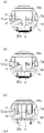
FIG. 1A is a vertical sectional view illustrating a structure of a vacuum pump having a washer with a relatively small thickness according to an embodiment of the present invention,FIG. 1B is a vertical sectional view illustrating a structure of a vacuum pump having a washer with a relatively medium thickness according to the embodiment of the present invention, andFIG. 1C is a vertical sectional view illustrating a structure of the vacuum pump having a washer with a relatively large thickness according to the embodiment of the present invention; -
FIG. 2A is an enlarged view of an A part inFIG. 1A ,FIG. 2B is an enlarged view of the A part inFIG. 1B , andFIG. 2C is an enlarged view of the A part inFIG. 1C ; -
FIG. 3 is a graph illustrating a relationship between a position of a rotating shaft and a positional sensor detection value; -
FIG. 4 is a graph illustrating a relationship between an electric current value flowing through an electromagnet and a magnetic attracting force caused by the electromagnet of a magnetic bearing to act on the rotating shaft; -
FIG. 5 is a graph illustrating a relationship between a rotational frequency of the rotating shaft and a natural frequency of a rotor when an inertia moment ratio γ of the rotor is smaller than 1; -
FIG. 6 is a graph illustrating the relationship between the rotational frequency of the rotating shaft and the natural frequency of the rotor when the inertia moment ratio γ of the rotor is equal to 1; -
FIG. 7 is a graph illustrating the relationship between the rotational frequency of the rotating shaft and the natural frequency the rotor when the inertia moment ratio γ of the rotor is larger than 1; and -
FIG. 8 is a graph illustrating a relationship between a rotation number of the rotating shaft and (the natural frequency of the rotor - the rotational frequency of the rotating shaft)/the rotational frequency of the rotating shaft in each of the inertia moment ratios γ of the rotor. - A vacuum pump, a rotor, and a washer according to an embodiment of the present invention will be described by referring to the following drawings. A
vacuum pump 1 is a turbo-molecular pump and, as shown inFIGS. 1A to 1C , has anouter cylinder portion 11, abase portion 12 to which theouter cylinder portion 11 is fixed, and arotor 2 rotatably accommodated in acasing 10 constituted by theouter cylinder portion 11 and thebase portion 12. An upper side inFIGS. 1A to 1C of theouter cylinder portion 11 is open and constitutes aninlet port 11a for a gas (gas), while anoutlet port 12a for a gas is formed in a side surface on a lower side inFIGS. 1A to 1C of thebase portion 12. Aflange portion 11b is formed on theinlet port 11a side of theouter cylinder portion 11, and by fixing thisflange portion 11b to a vacuum chamber of a semiconductor manufacturing device, for example, the gas in the vacuum chamber can be exhausted via theinlet port 11a. - The
rotor 2 has a rotormain body 20, arotating shaft 3, and awasher 7. Therotating shaft 3 is rotatably supported in thecasing 10 so as to rotate therotor 2. On an outer peripheral surface on the upper side inFIGS. 1A to 1C of the rotormain body 20, a plurality of blade-shapedrotor blades 21 inclined at a predetermined angle are integrally formed. Therotor blades 21 are provided radially with respect to an axis of therotating shaft 3 of therotor 2 and are provided in multi-stages in an axis direction of therotating shaft 3 of therotor 2.Stator blades 4 are provided between therotor blades 21 at each stage, and therotor blades 21 and thestator blades 4 are alternately disposed in the axis direction of therotating shaft 3 of therotor 2. Thestator blades 4 are also formed in plural, each having a blade shape inclined at a predetermined angle. Since an outer peripheral end is sandwiched between a plurality of ring-shapedspacers 5 for stator blade stacked in stages in theouter cylinder portion 11, thestator blades 4 are disposed radially and in multi-stages between therotor blades 21. - Between the
spacer 5 for stator blade disposed on a lowermost stream side and thebase portion 12, a threadedspacer 6 is provided. The threadedspacer 6 is formed cylindrically and has aspiral thread groove 6a formed on an inner peripheral surface. Acylinder portion 22 with the axis of therotating shaft 3 as a center is formed on a lower side (downstream side in which the gas is transferred) inFIGS. 1A to 1C of the rotormain body 20, and an outer peripheral surface of thecylinder portion 22 and the inner peripheral surface in which thethread groove 6a of the threadedspacer 6 is formed are disposed so as to oppose each other in proximity. A space defined by the outer peripheral surface of thecylinder portion 22 and thethread groove 6a of the threadedspacer 6 communicates with theoutlet port 12a. - The washers 7 (7a, 7b, 7c) are formed in a disc state with the axis of the
rotating shaft 3 as the center. Each of thewashers rotor 2 by adjusting the thickness of the washer is one of features of the present invention. In thewashers FIGS. 2A to 2C , aninsertion hole 7d for rotating shaft through which therotating shaft 3 is inserted is formed at a center, and aninsertion hole 7e for bolt through which abolt 71 for fixing the rotormain body 20 to therotating shaft 3 is inserted and aninsertion hole 7f for screw through which a screw, not shown, for balancing therotor 2 is inserted are formed radially. - After an upper part in
FIGS. 1A to 1C of therotating shaft 3 is inserted through aninsertion hole 20a for rotating shaft formed in the rotormain body 20 and theinsertion hole 7d for rotating shaft formed in thewashers bolt 71 is inserted through theinsertion hole 7e for bolt and screwed with the rotormain body 20 and therotating shaft 3 so that the rotormain body 20 is fixed to therotating shaft 3. At this time, thewashers rotating shaft 3 together with the rotormain body 20. - In the
vacuum pump 1, when therotor 2 is rotated at a high speed, therotor blades 21 hit gas molecules taken in through theinlet port 11a so as to cause the gas molecules to go toward the downstream side, and the hit gas molecules collide against the alternately disposedstator blades 4 and go downward and are further hit by therotor blade 21 on a subsequent stage and go toward the downstream side, and this operation is sequentially repeated up to therotor blade 21 and thestator blade 4 on lowermost stages, whereby the gas sent to the threadedspacer 6 is sent to theoutlet port 12a while being guided by thethread groove 6a, and the gas is exhausted from theoutlet port 12a. - In vicinities of an upper side and a lower side (an upstream side and a downstream side where the gas flows) in
FIGS. 1A to 1C of therotating shaft 3, aprotective bearing 31 is disposed. Theprotective bearing 31 prevents thevacuum pump 1 from being broken due to contacting and supporting of therotating shaft 3 when a radialmagnetic bearing 33 and an axialmagnetic bearing 34, which will be described later, become uncontrollable at abnormality or the like. A clearance between theprotective bearing 31 and therotating shaft 3 is designed to approximately 50 to 100 µm in total at the minimum in the radial direction. - The
rotating shaft 3 is rotated/driven by a direct-current brushless motor 32. The two radialmagnetic bearings 33 support therotating shaft 3 in the radial direction, and the axialmagnetic bearing 34 supports therotating shaft 3 in the axial direction. The two radialmagnetic bearings 33 are disposed with themotor 32 between them. Therotating shaft 3 is floated/supported by these radialmagnetic bearings 33 and the axialmagnetic bearing 34. - Each of the two radial
magnetic bearings 33 has fourelectromagnets 33a which cause a magnetic attracting force to act on therotating shaft 3, and the fourelectromagnets 33a are disposed in two each with therotating shaft 3 between them on two coordinate axes orthogonal to the axis of therotating shaft 3 and orthogonal to each other. Moreover, each of the two radialmagnetic bearings 33 has four inductance type or eddy-current typepositional sensors 33b which detect a radial position of therotating shaft 3. The fourpositional sensors 33b are orthogonal to the axis of therotating shaft 3 and are disposed in two each with therotating shaft 3 between them on the two coordinate axes in parallel with the above-described coordinate axis and orthogonal to each other. - On the
rotating shaft 3, a disc 8 (hereinafter, referred to as an "armature disc") of a magnetic body with the axis of therotating shaft 3 as a center is provided. The axialmagnetic bearing 34 has twoelectromagnets 34a which cause the magnetic attracting force to act on thearmature disc 8. The twoelectromagnets 34a are disposed with thearmature disc 8 between them, respectively. Moreover, the axialmagnetic bearing 34 has an inductance-type or an eddy-current typepositional senor 34b which detects an axial position of therotating shaft 3. It is to be noted that the inductance-type or eddy-current typepositional sensor 33b of the radialmagnetic bearing 33 and the inductance-type or eddy-current typepositional sensor 34b of the axialmagnetic bearing 34 have structures similar to that of the electromagnet and are disposed by having a core around which a conductor coil is wound opposed to therotating shaft 3. - A
stator 9 is stood on thebase portion 12 in order to protect the radialmagnetic bearing 33, the axialmagnetic bearing 34, themotor 32 and the like from the taken-in gas. - The
vacuum pump 1 includes a controller, not shown, which supplies electricity to the radialmagnetic bearing 33, the axialmagnetic bearing 34, and themotor 32 and sends/receives a signal to/from thepositional sensors positional sensors magnetic bearing 33 and the axialmagnetic bearing 34. The conductor coils wound around the cores of thepositional sensors rotating shaft 3, an amplitude of the voltage applied to the conductor coil is changed in accordance with this change in the inductance, and by detecting a changed amplitude value thereof, the controller detects a position of therotating shaft 3. This amplitude value (positional sensor detection value EO) has, as shown inFIG. 3 , non-linearity which is curvedly increased or decreased with respect to the change in the position of therotating shaft 3. Since a sum EO1 + EO2 (or a difference depending on how positive/negative signs are defined) of the amplitude values of the twopositional sensors 33b opposed to each other with therotating shaft 3 between them on each of the above-described coordinate axes has pseudo-linearity with respect to the change in the position of therotating shaft 3, the controller calculates the sum (difference), enables application of a linear control theory by using the value as a detection signal of thepositional sensor 33b, and controls the position of therotating shaft 3 on the basis of the theory. The controller causes the position of therotating shaft 3 to match a target position by feedback control which adjusts an electric current value caused to flow through theelectromagnet 33a on the basis of the sum (difference) of the detection signals of the twopositional sensors 33b on each of the coordinate axes. - The magnetic attracting force f caused by each of the
electromagnets 33a of the radialmagnetic bearing 33 to act on therotating shaft 3 also has non-linearity which is curvedly increased or decreased with respect to a change in the electric current flowing through theelectromagnets 33a as shown inFIG. 4 . Thus, regarding the twoelectromagnets 33a opposed with therotating shaft 3 between them on each of the coordinate axes, the electric current value is adjusted such that an electric current at an electric current value (I0 + i1) obtained by adding an electric current value i1 to a predetermined direct-current electric current value I0 (hereinafter, referred to as a "bias electric-current value") is caused to flow through theelectromagnet 33a whose distance from therotating shaft 3 is larger because therotating shaft 3 is shifted from the target position, while an electric current at an electric current value (I0 - i1) obtained by subtracting the electric current value i1 from this bias electric-current value I0 is caused to flow through theelectromagnet 33a whose distance from therotating shaft 3 is small. As described above, by setting a sum fhx1 + (-fhx2) of the magnetic attracting force caused to act by the twoelectromagnets 33a to a magnetic attracting force caused to act on therotating shaft 3, it is so configured that the magnetic attracting force has pseudo linearity with respect to the change in the electric current value so that the above-described linear control theory can be applied. - A structure of the axial
magnetic bearing 34 is basically similar to the structure of the radialmagnetic bearing 33, but for the purpose of reduction in a required space or the like, it may be so constituted that, instead of disposition of the two positional sensors with thearmature disc 8 between them in the axis direction of therotating shaft 3, only one unit of thepositional sensor 34b is disposed, while another positional sensor is substituted by a coil having a predetermined inductance disposed on a circuit board inside the controller. In this case, since the inductance of the coil provided on the circuit board has a predetermined value, while the amplitude value of the alternating voltage is a predetermined value, accuracy of linearity of the sum (difference) of the two positional sensors with respect to the change in the position of therotating shaft 3 is lowered, but it is useful if thevacuum pump 1 can be operated normally. - By the way, the
rotor 2 is floated/supported in the air by these radialmagnetic bearing 33 and axialmagnetic bearing 34, but since the supporting force has a component of the force in proportion to a change in a position of therotor 2, that is, a component corresponding to an elastic force, therotor 2 has a natural frequency corresponding to a mass or an inertia moment thereof. Therotor 2 floated in the air has three degrees of freedom in each of axial directions of a three-dimensional orthogonal coordinate whose one coordinate axis (hereinafter, referred to as a "z-axis") matched with the axis of therotating shaft 3 and three degrees of freedom around each of the axes, that is, six degrees of freedom in total, and five degrees of freedom excluding one degree of freedom around the z-axis whose rotational angle is controlled by themotor 32 receive the supporting forces of the radialmagnetic bearing 33 and the axialmagnetic bearing 34 and thus, therotor 2 has the natural frequency according to the supporting forces of the radialmagnetic bearing 33 and the axialmagnetic bearing 34. Particularly, in two degrees of freedom around two axes (hereinafter, referred to as an "x-axis" and a "y-axis", respectively) orthogonal to the z-axis and orthogonal to each other, a motion equation of therotor 2 has a term in proportion to a rotation speed around the other axis (hereinafter, referred to as an "interference term") as shown in the following expression (2) expressing a motion equation around the x-axis and the following expression (3) expressing a motion equation around the y-axis. Moreover, a size of this interference term is in proportion to a rotation speed of therotating shaft 3 rotated by themotor 32. - [Math. 1]


- However, in the above expressions (2) and (3), J denotes an inertia moment around the x-axis or the y-axis of the
rotor 2, Jz is an inertia moment around the z-axis of therotor 2, C denotes a viscosity resistance coefficient around the x-axis or the y-axis, θx is a rotational angle around the x-axis of therotor 2, θy is a rotational angle around the y-axis of therotor 2, and θz is a rotational angle around the z-axis of therotor 2. Moreover, in the above expression (2), Dx denotes a disturbance moment acting around the x-axis, and Gx is a spring constant of a moment around the x-axis generated by the supporting force of the radialmagnetic bearing 33 in the x-axis direction. Furthermore, in the above expression (3), Dy is a disturbance moment acting around the y-axis, and Gy is a spring constant of a moment around the y-axis generated by the supporting force of the radialmagnetic bearing 33 in the y-axis direction. Dx and Dy are generated by imbalance of therotor 2, an exhaust load of thevacuum pump 1 or the like. Gx and Gy actually have frequency characteristics according to a control design of the radialmagnetic bearing 33. It is to be noted that since therotor 2 has the rotormain body 20, therotating shaft 3, and the washer 7 (7a, 7b, 7c) as described above, the inertia moment Jz and the inertia moment J are inertia moments of the rotormain body 20, therotating shaft 3, and the washer 7 (7a, 7b, 7c) to be exact. - An expression for acquiring a natural frequency in each degree of freedom can be derived from the motion equation of each degree of freedom in usual, but regarding around the x-axis and around the y-axis of the radial
magnetic bearing 33, it is difficult to derive an expression for acquiring the natural frequency due to a reason that the respective motion equations have interference terms with respect to each other as described above or the like. Thus, a specific magnetic bearing was designed, and a value of the natural frequency of the specific magnetic bearing was acquired by relying on a trial production experiment and computer simulation using a finite element method in the past. - However, even though the natural frequency can be acquired for each of the specific magnetic bearings with these methods, qualitative analysis on how the natural frequency is changed when a set value is changed or the like cannot be conducted on the natural frequency. Thus, the natural frequency was acquired after a series of designs of a specific magnetic bearing were completed, and if the design was changed due to various reasons, the natural frequency was acquired again after a series of the design changes were completed, and in a case of nonconformity, a work of re-change of the design was needed, which took a large amount of time for the design of the magnetic bearing and the turbo-molecular pump.
- In the present invention, attention was paid to a fact that the radial
magnetic bearing 33 of thevacuum pump 1, which is a turbo-molecular pump, is used in vacuum, and two expressions (4) and (5) expressing natural frequencies ω1, ω2 of therotor 2, which are present in two each around the x-axis and the y-axis were derived from the above-described expressions (2) and (3) by setting the viscosity resistance coefficient C = 0. There are two natural frequencies expressed by the expressions (4), (5) on both around the x-axis and around the y-axis. - [Math. 2]


- The following expression (1) expresses a ratio γ of the inertia moment Jz around the z-axis to the inertia moment J around the x-axis or the y-axis (hereinafter, referred to as an "inertia moment ratio γ"). In the present invention, attention is also paid to a fact that a relationship between the natural frequencies ω1, ω2 of the
rotor 2 and the rotational frequency of therotating shaft 3 is different depending on whether the value of the inertia moment γ of therotor 2 expressed by the following expression (1) is equal to 1 or not, and if not, on whether it is larger or smaller than 1.
- First, as shown in
FIGS. 5 to 7 , the natural frequencies ω1, ω2 of therotor 2 have the same value, regardless of the value of the inertia moment ratio γ, when therotating shaft 3 is not rotated, and the rotational frequency Ωz is 0. When therotating shaft 3 starts rotation, and the rotational frequency Ωz increases, the natural frequency ω1, decreases, while the natural frequency ω2 increases. When the inertia moment ratio γ is smaller than 1, as shown inFIG. 5 , the natural frequency ω2 gets closer to the rotational frequency Ωz and after matching with the rotational frequency Ωz, it goes away from the rotational frequency Ωz. When the inertia moment ratio γ is equal to 1, as shown inFIG. 6 , a straight line representing the rotational frequency Ωz becomes like an asymptotic line, and the natural frequency ω2 gets closer to the rotational frequency Ωz. When the inertia moment ratio γ is larger than 1, as shown inFIG. 7 , it is known that the natural frequency ω2 does not match the rotational frequency Ωz but it goes away. - When the natural frequencies ω1, ω2 match the rotational frequency Ωz of the
rotating shaft 3 or a value close to that, resonance of therotor 2 is induced, it becomes difficult for the radialmagnetic bearing 33 and the axialmagnetic bearing 34 to float/support therotor 2, and continuous vibration of therotor blade 21 and repeated fluctuation of the stress lead to a fatigue failure. Thus, even if the natural frequencies ω1, ω2 temporarily get closer to or match the rotational frequency Ωz of therotating shaft 3, it is desirable that it promptly goes away from the rotational frequency Ωz after that. - A rotor of a conventional turbo-molecular pump has a value of the inertia moment ratio γ smaller than 1, but in the
vacuum pump 1 with exhaustion of a large flowrate of gas which will be required for a semiconductor manufacturing device in the future, for example, therotor 2 needs to be made larger in a radial direction of therotating shaft 3. Thus, the inertia moment Jz around the z-axis is increased, and the value of the inertia moment ratio γ becomes larger to a value closer to 1, but as the inertia moment ratio γ gets closer to 1, the natural frequency ω2 gets closer to the rotational frequency Ωz, and particularly when natural frequency ω2 matches the rotational frequency Ωz, therotor 2 vibrates as above and then, the fatigue failure would occur in therotor blade 21. Therefore, the present invention is characterized in that, when therotor 2 is made larger in the radial direction of therotating shaft 3, the value of the inertia moment ratio γ is set to a value larger than 1. - Next, a method for reducing deflection, vibration of the
rotor 2 at steady rotation by adjusting a thickness of thewasher 7 so as to adjust a value of the inertia moment ratio γ of therotor 2 increasingly/decreasingly will be described. When the thickness of the washer 7 (7a, 7b, 7c) with the axis of therotating shaft 3 as a center is adjusted, changed as shown inFIGS. 1A to 1C andFIGS. 2A to 2C , the inertia moment J around the x-axis or the y-axis of therotor 2 is increased/decreased and thus, the value of the inertia moment ratio γ can be adjusted, changed increasingly/decreasingly. Table 1 shows an example of a relationship between the thickness of thewasher 7 and the inertia moment ratio γ. As known from Table 1, by reducing the thickness of thewasher 7, the inertia moment ratio γ becomes larger, while by increasing the thickness of thewasher 7, the inertia moment ratio γ becomes smaller.[Table 1] Washer thickness 5.5 mm 14 mm 21 mm 31 mm 43 mm Inertia moment ratio γ 1.083 1.061 1.041 1.001 0.956 - A relationship between a rotation number of the
rotating shaft 3 at each of the inertia moment ratios γ of therotor 2 and (the natural frequency ω2 of the rotor 2 - the rotational frequency Ωz of the rotating shaft 3)/the rotational frequency Ωz of therotating shaft 3 is shown inFIG. 8 . Assuming that (the natural frequency ω2 of the rotor 2 - the rotational frequency Ωz of the rotating shaft 3)/the rotational frequency Ωz of therotating shaft 3 is α, a range of -0.08 < α < 0.08, for example, inFIG. 8 corresponds to a range in which deflection of therotor 2 becomes larger than 80 µm (peak to peak value; the same applies to the following). Since a clearance in the radial direction between therotating shaft 3 and theprotective bearing 31 is often designed to be 50 µm at the minimum over the entire circumference of therotating shaft 3 and approximately 100 µm for a total of the clearances on both sides with therotating shaft 3 between them, by setting the deflection of therotor 2 smaller than 80 µm, contact between therotating shaft 3 and theprotective bearing 31 can be prevented. - In order to set the deflection of the
rotor 2 smaller than 80 µm, it is only necessary to make adjustment such that α goes out of the range of -0.08 < α < 0.08 at the rotation number at the steady rotation of therotor 2 by adjusting the thickness of thewasher 7 so as to adjust the value of the inertia moment ratio γ increasingly/decreasingly. Specifically, when therotor 2 is designed with thewasher 7 with the predetermined thickness as a reference, adjustment can be made such that α at the rotation number at the steady rotation of therotor 2 becomes 0.08 or more by replacement to thewasher 7 with a thickness smaller than the predetermined so as to increase the value of the inertia moment ratio γ or such that α at the rotation number at the steady rotation of therotor 2 becomes -0.08 or less by replacement to thewasher 7 with a thickness larger than the predetermined so as to decrease the value of the inertia moment ratio γ. - By preparing some kinds of the
washers 7 with different thicknesses in advance, the inertia moment ratio γ can be adjusted by replacement to thewasher 7 with a thickness different from the predetermined thickness even after therotor 2 is designed with thewasher 7 with the predetermined thickness as a reference. - As described above, in this embodiment, when the
rotor 2 is made larger in the radial direction of therotating shaft 3, for example, the value of the inertia moment ratio γ of therotor 2 is set to a value larger than 1 and thus, the natural frequency ω2 of therotor 2 can be prevented from getting closer to the rotational frequency Ωz of therotating shaft 3, and vibration of therotor 2 can be reduced. - Moreover, in this embodiment, by adjusting the thickness of the
washer 7 through replacement of thewasher 7 which would hardly affect other components even if after replacement or adjustment with thewasher 7 with a different thickness or the like, the value of the inertia moment ratio γ of therotor 2 is adjusted increasingly/decreasingly so that the deflection, vibration of therotor 2 at the steady rotation can be reduced and thus, works such as balancing of therotor 2 and the adjustment of the value of γ are facilitated, the number of processes can be reduced, and cost reduction can be realized. - As described above, the present invention has been described by citing the embodiments, but the present invention is not limited to each of the above embodiments but is capable of various variations other than the above-described variations. For example, in the above-described embodiments, the example in which the thickness of the
washer 7 is adjusted in order to reduce the deflection of therotor 2 smaller than 80 µm was described, but an allowed deflection width of therotor 2 can be set by changing as appropriate depending on an application, a size, a shape, a type and the like of the vacuum pump. - Moreover, in the present invention, it is also possible to adjust the value of the inertia moment ratio γ of the
rotor 2 to a value larger than 1 by adjusting the thickness of thewasher 7 when therotor 2 is made larger in the radial direction of therotating shaft 3, for example. - Furthermore, in the above-described embodiment, the case in which the
rotor 2 has thewasher 7 was described, but even with therotor 2 which does not have thewasher 7, the value of the inertia moment ratio γ of therotor 2 can be a value larger than 1, and in this case, the inertia moment Jz and the inertia moment J are inertia moments of the rotormain body 20 and therotating shaft 3. - Furthermore, in the above-described embodiment, the example in which the
vacuum pump 1 is used for the semiconductor manufacturing device was described, but thevacuum pump 1 can be also used similarly for an electron microscope, a surface analyzer, a micromachining device and the like other than that. -
- 1
- Vacuum pump
- 10
- Casing
- 11
- Outer cylinder portion
- 12
- Base portion
- 11a
- Inlet port
- 12a
- Outlet port
- 2
- Rotor
- 20
- Rotor main body
- 21
- Rotor blade
- 22
- Cylinder portion
- 3
- Rotating shaft
- 31
- Protective bearing
- 32
- Motor
- 33
- Radial magnetic bearing
- 33a
- Electromagnet
- 33b
- Positional sensor
- 34
- Axial magnetic bearing
- 34a
- Electromagnet
- 34b
- Positional sensor
- 4
- Stator blade
- 5
- Spacer for stator blade
- 6
- Threaded spacer
- 6a
- Thread groove
- 7 (7a, 7b, 7c)
- Washer
- 8
- Disc (armature disc)
- 9
- Stator
Claims (10)
- A vacuum pump, comprising:a casing having an inlet port and an outlet port;a rotor having a rotating shaft;a magnetic bearing which rotatably supports the rotating shaft; anda motor which rotates/drives the rotating shaft; andtransferring a gas taken in through the inlet port to the outlet port by rotation of the rotor, whereina value of γ expressed in an expression (1) below is larger than 1:

- The vacuum pump according to claim 1, whereinthe rotor has a plurality of rotor blades formed on an outer peripheral surface; andthe vacuum pump is a turbo-molecular pump having a plurality of stator blades provided in the casing and disposed alternately with the rotor blades in an axis direction of the rotating shaft.
- The vacuum pump according to claim 2, whereinthe rotor has a cylinder portion with an axis of the rotating shaft as a center on a downstream side to which the gas is transferred from the rotor blade; andthe vacuum pump includes a spacer provided in the casing and having a thread groove formed on an inner peripheral surface by opposing the cylinder portion.
- A rotor used in a vacuum pump including:a casing having an inlet port and an outlet port;a magnetic bearing which rotatably supports a rotating shaft; anda motor which rotates/drives the rotating shaft; accommodated in the casing and having the rotating shaft; and transferring a gas taken in through the inlet port to the outlet port by rotation, whereina value of γ expressed in an expression (1) below is larger than 1:

- A vacuum pump, comprising:a casing having an inlet port and an outlet port;a rotor having a rotating shaft and a disc-shaped washer with an axis of the rotating shaft as a center;a magnetic bearing which rotatably supports the rotating shaft; anda motor which rotates/drives the rotating shaft; andtransferring a gas taken in through the inlet port to the outlet port by rotation of the rotor, whereina value of γ expressed in an expression (1) below can be adjusted by adjusting a thickness of the washer:

- The vacuum pump according to claim 5, whereinwith the washer with a predetermined thickness as a reference,deflection of the rotor at steady rotation is decreased by decreasing the value of γ expressed in the above-described expression (1) by increasing a thickness of the washer or by increasing the value of γ expressed in the above-described expression (1) by decreasing the thickness of the washer.
- The vacuum pump according to claim 6, wherein
deflection of the rotor at steady rotation is set smaller than 80 µm. - The vacuum pump according to claim 5, wherein
a thickness of the washer is adjusted such that a value of γ expressed in the above-described expression (1) is larger than 1. - A rotor used in a vacuum pump including:a casing having an inlet port and an outlet port;a magnetic bearing which rotatably supports a rotating shaft; anda motor which rotates/drives the rotating shaft;accommodated in the casing and having the rotating shaft and a disc-shaped washer with an axis of the rotating shaft as a center; andtransferring a gas taken in through the inlet port to the outlet port by rotation, whereina value of γ expressed in an expression (1) below can be adjusted by adjusting a thickness of the washer:

- A washer used in a vacuum pump including a casing having an inlet port and an outlet port, a rotor having a rotating shaft, a magnetic bearing which rotatably supports the rotating shaft, and a motor which rotates/drives the rotating shaft, and transferring a gas taken in through the inlet port to the outlet port by rotation of the rotor;having a disc shape with an axis of the rotating shaft as a center; andprovided in the rotor, whereina value of γ expressed in an expression (1) below can be adjusted by adjusting a thickness:

Applications Claiming Priority (2)
| Application Number | Priority Date | Filing Date | Title |
|---|---|---|---|
| JP2019130636A JP2021014834A (en) | 2019-07-12 | 2019-07-12 | Vacuum pump, rotor and metal washer |
| PCT/JP2020/026285 WO2021010196A1 (en) | 2019-07-12 | 2020-07-03 | Vacuum pump, rotor, and washer |
Publications (2)
| Publication Number | Publication Date |
|---|---|
| EP3998407A1 true EP3998407A1 (en) | 2022-05-18 |
| EP3998407A4 EP3998407A4 (en) | 2023-07-26 |
Family
ID=74210680
Family Applications (1)
| Application Number | Title | Priority Date | Filing Date |
|---|---|---|---|
| EP20839823.0A Withdrawn EP3998407A4 (en) | 2019-07-12 | 2020-07-03 | Vacuum pump, rotor, and washer |
Country Status (6)
| Country | Link |
|---|---|
| US (1) | US11946482B2 (en) |
| EP (1) | EP3998407A4 (en) |
| JP (1) | JP2021014834A (en) |
| KR (1) | KR102921978B1 (en) |
| CN (1) | CN114026333B (en) |
| WO (1) | WO2021010196A1 (en) |
Family Cites Families (24)
| Publication number | Priority date | Publication date | Assignee | Title |
|---|---|---|---|---|
| DE1806703C3 (en) * | 1968-11-02 | 1975-06-26 | Siemens Ag, 1000 Berlin Und 8000 Muenchen | Process for the production of porous catalytically active electrodes |
| SU1036956A1 (en) * | 1981-03-24 | 1983-08-23 | Предприятие П/Я Г-4857 | Vertical turbo-molecular pump |
| GB9125848D0 (en) | 1991-12-04 | 1992-02-05 | Boc Group Plc | Improvements in vacuum pumps |
| FR2715201B1 (en) * | 1994-01-19 | 1996-02-09 | Inst Nat Polytech Grenoble | Magnetic bearing and assembly comprising a stator part and a rotor part suspended by such a bearing. |
| JP3776162B2 (en) * | 1996-05-10 | 2006-05-17 | Ntn株式会社 | Magnetic levitation blood pump |
| JPH10252683A (en) | 1997-03-06 | 1998-09-22 | Hitachi Ltd | Dry vacuum pump |
| US5894181A (en) * | 1997-07-18 | 1999-04-13 | Imlach; Joseph | Passive magnetic bearing system |
| JP3266559B2 (en) * | 1997-08-26 | 2002-03-18 | 三星電機株式会社 | Brushless DC motor |
| JP3974772B2 (en) * | 2001-11-16 | 2007-09-12 | Bocエドワーズ株式会社 | Vacuum pump |
| JP2003244891A (en) | 2002-02-20 | 2003-08-29 | Honda Motor Co Ltd | Flywheel battery |
| JP2005083524A (en) * | 2003-09-10 | 2005-03-31 | Nissan Motor Co Ltd | Flywheel |
| JP2005105846A (en) * | 2003-09-26 | 2005-04-21 | Boc Edwards Kk | Vacuum pump |
| JP2005180265A (en) | 2003-12-18 | 2005-07-07 | Boc Edwards Kk | Vacuum pump |
| JP4713329B2 (en) | 2005-12-21 | 2011-06-29 | Ntn株式会社 | Rolling bearing |
| JP5087418B2 (en) * | 2008-02-05 | 2012-12-05 | 株式会社荏原製作所 | Turbo vacuum pump |
| JP4934089B2 (en) * | 2008-04-09 | 2012-05-16 | 株式会社荏原製作所 | Turbo molecular pump |
| JP5719592B2 (en) * | 2008-07-14 | 2015-05-20 | エドワーズ株式会社 | Vacuum pump |
| WO2010095218A1 (en) | 2009-02-18 | 2010-08-26 | 株式会社 島津製作所 | Turbo-molecular pump |
| JP5864111B2 (en) * | 2011-02-08 | 2016-02-17 | エドワーズ株式会社 | Rotating body and vacuum pump equipped with the rotating body |
| JP5989645B2 (en) * | 2011-07-14 | 2016-09-07 | エドワーズ株式会社 | Thread groove type vacuum pump and vacuum exhaust system using the same |
| KR20140105550A (en) | 2011-12-13 | 2014-09-01 | 다이킨 고교 가부시키가이샤 | Resin composition and molded article |
| EP2887153B1 (en) * | 2013-12-19 | 2023-06-28 | Montres Breguet SA | Magnetic centring device |
| EP3034875B1 (en) | 2014-12-18 | 2020-11-04 | Valeo Japan Co., Ltd. | Refrigerant compressor |
| US10351247B2 (en) | 2015-06-15 | 2019-07-16 | Subaru Corporation | Wing and anti-icing system |
-
2019
- 2019-07-12 JP JP2019130636A patent/JP2021014834A/en active Pending
-
2020
- 2020-07-03 EP EP20839823.0A patent/EP3998407A4/en not_active Withdrawn
- 2020-07-03 CN CN202080046700.8A patent/CN114026333B/en active Active
- 2020-07-03 US US17/625,165 patent/US11946482B2/en active Active
- 2020-07-03 KR KR1020217042045A patent/KR102921978B1/en active Active
- 2020-07-03 WO PCT/JP2020/026285 patent/WO2021010196A1/en not_active Ceased
Also Published As
| Publication number | Publication date |
|---|---|
| CN114026333B (en) | 2024-11-15 |
| KR20220032527A (en) | 2022-03-15 |
| KR102921978B1 (en) | 2026-02-03 |
| JP2021014834A (en) | 2021-02-12 |
| CN114026333A (en) | 2022-02-08 |
| EP3998407A4 (en) | 2023-07-26 |
| US11946482B2 (en) | 2024-04-02 |
| US20220268289A1 (en) | 2022-08-25 |
| WO2021010196A1 (en) | 2021-01-21 |
Similar Documents
| Publication | Publication Date | Title |
|---|---|---|
| Zheng et al. | Rotor balancing for magnetically levitated TMPs integrated with vibration self-sensing of magnetic bearings | |
| US8360728B2 (en) | Aircraft with transient-discriminating propeller balancing system | |
| EP1396649B1 (en) | Magnetic bearing device with vibration restraining function, magnetic bearing device with vibration estimating function, and pump device with the magnetic bearing devices mounted thereto | |
| CN110118632B (en) | Method for measuring the unbalance of a shaft-elastic rotor by means of a displacement sensor | |
| Han et al. | Design aspects of a large scale turbomolecular pump with active magnetic bearings | |
| JP2012251486A (en) | Magnetic levitation vacuum pump, whirling estimation method, rotor balance inspection method, and method for adjusting magnetic bearing control gain | |
| WO2012070278A1 (en) | Magnetic bearing control device, and exhaust pump provided with the device | |
| US11333154B2 (en) | Vacuum pump with a rotary body in a case with the rotary body having at least three balance correction portions accessible from an outside of the case for balance correction by an n-plane method | |
| US8366380B2 (en) | Turbo-molecular pump and method of assembling turbo-molecular pump | |
| US9388854B2 (en) | Magnetic bearing apparatus and method for reducing vibration caused by magnetic bearing apparatus | |
| CN115425817A (en) | High-precision dynamic balance correction device and method for magnetic suspension rotor | |
| KR20190141134A (en) | Vacuum pumps, magnetic bearing devices and rotors | |
| US11946482B2 (en) | Vacuum pump, rotor, and washer | |
| CN114729646B (en) | Vacuum exhaust device and vacuum pump for the same | |
| JP7427437B2 (en) | Vacuum evacuation equipment and vacuum pump used therein | |
| JP7214805B1 (en) | Magnetic bearing device and vacuum pump | |
| JP3561774B2 (en) | Turbo molecular pump | |
| JP2003232292A (en) | Vacuum pump | |
| JPH06147191A (en) | Magnetic bearing mounted centrifugal compressor and centrifugal fluid machinery |
Legal Events
| Date | Code | Title | Description |
|---|---|---|---|
| STAA | Information on the status of an ep patent application or granted ep patent |
Free format text: STATUS: THE INTERNATIONAL PUBLICATION HAS BEEN MADE |
|
| PUAI | Public reference made under article 153(3) epc to a published international application that has entered the european phase |
Free format text: ORIGINAL CODE: 0009012 |
|
| STAA | Information on the status of an ep patent application or granted ep patent |
Free format text: STATUS: REQUEST FOR EXAMINATION WAS MADE |
|
| 17P | Request for examination filed |
Effective date: 20220208 |
|
| AK | Designated contracting states |
Kind code of ref document: A1 Designated state(s): AL AT BE BG CH CY CZ DE DK EE ES FI FR GB GR HR HU IE IS IT LI LT LU LV MC MK MT NL NO PL PT RO RS SE SI SK SM TR |
|
| DAV | Request for validation of the european patent (deleted) | ||
| DAX | Request for extension of the european patent (deleted) | ||
| A4 | Supplementary search report drawn up and despatched |
Effective date: 20230627 |
|
| RIC1 | Information provided on ipc code assigned before grant |
Ipc: F04D 29/66 20060101ALI20230621BHEP Ipc: F04D 29/26 20060101ALI20230621BHEP Ipc: F04D 19/04 20060101AFI20230621BHEP |
|
| STAA | Information on the status of an ep patent application or granted ep patent |
Free format text: STATUS: EXAMINATION IS IN PROGRESS |
|
| 17Q | First examination report despatched |
Effective date: 20250423 |
|
| STAA | Information on the status of an ep patent application or granted ep patent |
Free format text: STATUS: THE APPLICATION IS DEEMED TO BE WITHDRAWN |
|
| 18D | Application deemed to be withdrawn |
Effective date: 20250826 |