EP3998129A1 - Cutting tool - Google Patents
Cutting tool Download PDFInfo
- Publication number
- EP3998129A1 EP3998129A1 EP20837611.1A EP20837611A EP3998129A1 EP 3998129 A1 EP3998129 A1 EP 3998129A1 EP 20837611 A EP20837611 A EP 20837611A EP 3998129 A1 EP3998129 A1 EP 3998129A1
- Authority
- EP
- European Patent Office
- Prior art keywords
- head portion
- holder
- shank
- engaging
- cutting tool
- Prior art date
- Legal status (The legal status is an assumption and is not a legal conclusion. Google has not performed a legal analysis and makes no representation as to the accuracy of the status listed.)
- Granted
Links
Images










Classifications
-
- B—PERFORMING OPERATIONS; TRANSPORTING
- B23—MACHINE TOOLS; METAL-WORKING NOT OTHERWISE PROVIDED FOR
- B23B—TURNING; BORING
- B23B29/00—Holders for non-rotary cutting tools; Boring bars or boring heads; Accessories for tool holders
- B23B29/04—Tool holders for a single cutting tool
- B23B29/12—Special arrangements on tool holders
-
- B—PERFORMING OPERATIONS; TRANSPORTING
- B23—MACHINE TOOLS; METAL-WORKING NOT OTHERWISE PROVIDED FOR
- B23B—TURNING; BORING
- B23B27/00—Tools for turning or boring machines; Tools of a similar kind in general; Accessories therefor
- B23B27/14—Cutting tools of which the bits or tips or cutting inserts are of special material
- B23B27/16—Cutting tools of which the bits or tips or cutting inserts are of special material with exchangeable cutting bits or cutting inserts, e.g. able to be clamped
- B23B27/1685—Adjustable position of the cutting inserts
- B23B27/1692—Angular position of the cutting insert adjustable around an axis parallel to the chip-forming plane
-
- B—PERFORMING OPERATIONS; TRANSPORTING
- B23—MACHINE TOOLS; METAL-WORKING NOT OTHERWISE PROVIDED FOR
- B23B—TURNING; BORING
- B23B29/00—Holders for non-rotary cutting tools; Boring bars or boring heads; Accessories for tool holders
- B23B29/04—Tool holders for a single cutting tool
- B23B29/046—Tool holders for a single cutting tool with an intermediary toolholder
-
- B—PERFORMING OPERATIONS; TRANSPORTING
- B23—MACHINE TOOLS; METAL-WORKING NOT OTHERWISE PROVIDED FOR
- B23B—TURNING; BORING
- B23B27/00—Tools for turning or boring machines; Tools of a similar kind in general; Accessories therefor
- B23B27/02—Cutting tools with straight main part and cutting edge at an angle
-
- B—PERFORMING OPERATIONS; TRANSPORTING
- B23—MACHINE TOOLS; METAL-WORKING NOT OTHERWISE PROVIDED FOR
- B23B—TURNING; BORING
- B23B29/00—Holders for non-rotary cutting tools; Boring bars or boring heads; Accessories for tool holders
-
- B—PERFORMING OPERATIONS; TRANSPORTING
- B23—MACHINE TOOLS; METAL-WORKING NOT OTHERWISE PROVIDED FOR
- B23B—TURNING; BORING
- B23B2260/00—Details of constructional elements
- B23B2260/084—Hirth couplings
-
- B—PERFORMING OPERATIONS; TRANSPORTING
- B23—MACHINE TOOLS; METAL-WORKING NOT OTHERWISE PROVIDED FOR
- B23B—TURNING; BORING
- B23B2260/00—Details of constructional elements
- B23B2260/088—Indication scales
Definitions
- the present invention relates to a cutting tool.
- Patent Document 1 As a cutting tool used for cutting processing of a work material, such as metal, a cutting tool disclosed in Patent Document 1 is known.
- a cutting tool including a head (main body 3) and a holder 2, which is connected to the back side of the main body 3, is disclosed.
- a seat portion 4 insert mounting seat
- the main body 3 is also provided with a male shaft 6 which extends backward from the rear end portion of the main body 3.
- this male shaft 6 is inserted into a seat 7 inside the holder 2, whereby the position of the main body 3, with respect to the holder 2, is fixed.
- Patent Document 1 WO1999/039852
- a cutting tool is a cutting tool extending along a center axis and including on a front end side a cutting insert to cut a work material, the cutting tool including: a head portion which includes an insert mounting seat, on which the cutting insert is installed, on a front end side; a holder which is installed on a rear end side of the head portion and holds the head portion; and a fixing member which fixes a position of the head portion with respect to the holder when the head portion is mounted on the holder.
- the head portion is configured to be mountable on the holder, with an angle thereof changing around the center axis.
- the cutting tool is fixed to the holder using the fixing member, with the angle of the head portion changing around the center axis, so as to maintain this state.
- the radial rake angle of the cutting insert disposed in the head portion can be changed.
- the head portion may include an engaging portion, constituted of a concave portion and/or a convex portion, on a connecting surface of the head portion that is connected to the holder, and the holder may include an engaged portion, constituted of a convex portion and/or a concave portion engaging with the engaging portion, on a surface of the holder that is connected to the head portion.
- the concave portion may be provided in plurality and formed on a peripheral area of the connecting surface in a circumferential direction.
- the concave portion may be formed at symmetric positions across the center axis.
- At least one of the head portion and the holder may have a scale, and a rotation angle of the head portion may be adjustable by setting with the scale.
- a ring portion may be further included, and on one end face of the ring portion, a first engaging portion, which engages with the engaging portion of the head portion, may be disposed, and on the other end face of the ring portion, a second engaging portion, which engages with the engaging portion of the holder, may be disposed, the head portion is configured to be engageable with the ring portion, with an angle thereof changing around the center axis, the holder may be configured to be engageable with a ring portion, with an angle thereof changing around the center axis, and the unit of change of the engaging angle of the head portion with respect to the ring portion may be different from the unit of change of the engaging angle of the holder with respect to the ring portion.
- the engaging portion of the holder may be constituted of at least one convex portion
- the second engaging portion of the ring portion may be constituted of a plurality of grooves with which the convex portion of the engaging portion of the holder engages
- the first engaging portion of the ring portion may be constituted of at least one convex portion
- the engaging portion of the head portion may be constituted of a plurality of grooves with which the convex portion of the first engaging portion of the ring portion engages.
- At least one of the head portion and the ring portion may have a scale corresponding to the unit of change of the engaging angle of the head portion with respect to the ring portion, at least one of the ring portion and the holder may have a scale corresponding to the unit of change of the engaging angle of the holder with respect to the ring portion, and a rotation angle of the head portion may be adjustable by setting with the scale.
- a cutting tool which can process helical flutes having different leads using one tool, so as to reduce the component storage cost, can be provided.
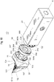
- FIG. 1 A configuration of a cutting tool 1 according to Embodiment 1 will be described with reference to Figs. 1 to 10 .
- This cutting tool 1 is a turning tool that rotates a work material to process it without rotating the tool.
- Figs. 1 to 4 are diagrams illustrating the configuration of the cutting tool 1.
- Figs. 5 to 7 are diagrams illustrating a configuration of a head portion 10.
- Figs. 8 to 10 are diagrams illustrating a configuration of a shank (holder) 20.
- the cutting tool 1 includes the shank 20, which extends along the center axis O, and a head portion 10.
- the head portion 10 is connected to the shank 20 on the front end side (left side in Fig. 2 ).
- the head portion 10 has an insert mounting seat 102 on the front end side thereof, and a cutting insert 101 is mounted on the insert mounting seat 102.
- the cutting insert 101 is removably installed on the insert mounting seat 102.
- the cutting insert 101 is installed in the insert mounting seat 102, so that a cutting edge 101a of the cutting insert 101 protrudes (left side in Fig. 2 ) from the front end of the head portion 10.
- the portion of the cutting edge 101a protruding from the head portion 10 is used for cutting processing.
- the shank 20 and the head portion 10 may be connected such that the tip of the cutting edge 101a of the cutting insert 101 is positioned on the axial line of the center axis O (that is, the center axis of the shank 20 and the center axis of the head portion 10 are on the same axis) in the top view ( Fig. 3 ).
- the cutting insert 101 of Embodiment 1 is an approximately square-shaped insert in the top view ( Fig. 3 ), but the present invention is not limited to the above mode, and the shape of the cutting insert 101 may be selected appropriately, so as to match with the shape of the helical flutes (e.g., screw shape, groove shape) to be processed.
- a male shaft 105 is disposed on the rear end side of the head portion 10 at the center area thereof, as illustrated in Figs. 5 to 7 .
- the male shaft 105 is disposed so as to protrude backward (right direction in Fig. 2 or Fig. 7 ) from the center area of the rear end face 11 (connecting surface 11 of the head portion 10 to be connected to the shank 20) of the head portion 10 in the extending direction of the center axis O (hereafter "axial direction").
- the male shaft 105 has an approximately cylindrical shape with the center axis O as the center.
- the male shaft 105 is disposed so that the male shaft 105 is inserted into a shaft hole 205a of a female shaft 205 disposed on the shank 20 when the head portion 10 is installed in the shank 20.
- Through holes 104 to which bolts 103 are inserted, are formed in the head portion 10 in the axial direction.
- the bolts 103 are inserted into the through holes 104 formed in the head portion 10, and tightened to the bolt fastening holes 203 of the shank 20, whereby the position of the head portion 10 with respect to the shank 20 is fixed.
- a shape of each through hole 104, to which each bolt 103 is inserted is a long hole of which major axis is bent in a circular-arc shape when the head portion 10 is viewed from the rear side, and is formed on the peripheral area of the connecting surface 11 in the circumferential direction.
- each bolt 103 and each bolt fastening hole 203 are not especially limited, and, for example, the bolt 103 may have a shaft portion in which a male screw is formed, and be screwed into the bolt fastening hole 203 in which a female screw is formed.
- the shank 20 is a member to hold the head portion 10, and is connected on the rear end side of the head portion 10.
- the shank 20 is extended such that the longitudinal direction thereof is along the center axis O, and has an approximately rectangular parallelepiped shape.
- the shank 20 has a female shaft 205 on the front end side thereof, so as to install the head portion 10.
- the female shaft 205 has an approximately cylindrical shape, and the shaft hole 205a, to insert the male shaft 105 of the head portion 10, is formed at the center area thereof.
- the bolt fastening hole 203, to fasten and fix the bolt 103, is formed at each position in the female shaft 205 corresponding to each through hole 104 of the head portion 10.
- the bolt fastening hole 203 is formed at a plurality of positions on the front end face 21 of the shank 20 in the circumferential direction at equal intervals.
- the shank 20 has an approximately rectangular parallelepiped shape, but the present invention is not limited to this example, and may have an approximately cylindrical shape or any other shape, for example, as long as the shank 20 is a member that is connected to the head portion 10 and has a function to hold the head portion 10.
- the male shaft 105 and the female shaft 205 are also not limited to the modes in the illustrations, and the shape, size, or the like thereof may be changed, as long as the head portion 10 and the shank 20 can be connected in the state after the rotation angle of the head portion 10 is adjusted.
- a number of bolts 103 (fixing members) and a number of bolt fastening holes 203, to which the bolts 103 are inserted are 3 respectively, but the present invention is not limited to this example, and may be a number of bolts 103 or bolt fastening holes 203 to fix the head portion 10 and the shank 20 may be 1, 2 or 4 or more. Further, in Embodiment 1, the bolt 103 is used as an example of the fixing member, but a different member may be used as the fixing member, as long as the member can fix the position of the head portion 10 with respect to the shank 20.
- the head portion 10 is configured to be mountable on the shank 20 with changing the angle around the center axis O.
- the head portion 10 can be fixed to the shank 20 in the state after the relative angle (rotational angle around the center axis O) of the head portion 10 with respect to the shank 20 is adjusted.
- the angle adjustment mechanism of the head portion 10 with respect to the shank 20 will now be described.
- a plurality of concave portions 107 are formed on the connecting surface 11, which is connected to the shank 20, of the head portion 10, and the concave portions 107 are engaged with the convex portions 207 of the shank 20 when the head portion 10 is installed in the shank 20.
- the position of the head portion 10 with respect to the shank 20 is adjusted, and the orientation thereof (mounting orientation of the cutting insert 101 installed on the front end of the head portion 10) can be held.
- the position of the head portion 10 with respect to the shank 20 is fixed by fastening the bolts 103.
- the connecting surface 11 has an approximately circular shape in the side view (when the head portion 10 is viewed from the rear end side, as illustrated in Fig. 6 ), and a plurality of concave portions 107 are formed on the peripheral area of the connecting surface 11 in the circumferential direction at equal intervals. Since a plurality of concave portions 107 are formed, the rotation angle of the head portion 10 with respect to the shank 20 can be adjusted in multiple steps.
- the concave portions 107 are formed in the peripheral area of the connecting surface 11 in the circumferential direction at 5° intervals, and the concave portions 107 as a whole can adjust the rotation angle of the head portion 10 in a -20° ⁇ ⁇ ⁇ 20° range, that is, in a ⁇ 20° range around the center axis O.
- the radial rake angle of the cutting insert 101 disposed in the head portion 10 can be changed by changing the angle of the head portion 10 around the center axis O, and fixing the shank 20 and the head portion 10 by fastening the bolts 103 such that this changed state can be maintained.
- processing at different radial rake angles can be implemented using one type of cutting insert 101.
- a reference position (radial rake angle of the cutting insert 101 is 0°) is a position where the head portion 10 is installed in the shank 20 (the concave portions 107 are engaged with the convex portions 207), such that an indication groove S1 of the head portion 10 is set to the position indicting 0° of the scale S2 of the shank 20, the head portion 10 can be installed in the shank 20 to perform cutting processing in a state after the radial rake angle of the cutting insert 101 is adjusted in a positive direction or a negative direction (-20° ⁇ ⁇ ⁇ 20°) from the reference position. Since processing at a different radial rake angle is possible, different helical flutes having different leads can be processed using one tool, whereby the component storage cost can be reduced.
- the concave portions 107 formed on the connecting surface 11 of the head portion 10 are formed at symmetric positions with respect to the center axis O in the -20° ⁇ ⁇ ⁇ 20° range ( Fig. 6 ) at 5° intervals.
- the convex portions 207 that engages with the concave portions 107 are formed at symmetric positions with respect to the center axis O.
- the present invention is not limited to this example, where the concave portions 107 and the convex portions 207 are at symmetric positions with respect to the center axis O.
- a plurality of concave portions 107 may be disposed at one location on the peripheral area of the connecting surface 11, and one convex portion 207 that engages with the concave portions 107 may be disposed, whereby the angle of the head portion 10 can be adjusted around the center axis O.
- the concave portions 107 may be disposed at 3 or more locations on the peripheral area of the connecting surface 11, and 3 or more convex portions 207 may be disposed so as to correspond to the concave portions 107.
- the positions and numbers of the concave portions 107 and the convex portions 207 may be changed, as long as the head portion 10 can be installed in the shank 20 with changing the angle around the center axis O.
- the scale S (indication groove S1 of the head portion 10 and scale S2 of the shank 20) that allow to visually recognize the adjusted angle of the head portion 10 are formed on the outer peripheral surface of the female shaft 205 disposed on the front end side of the shank 20.
- the indication groove S1 to the scale S2 of the shank 20
- the head portion 10 can be accurately set to an arbitrary angle compared with the configuration without the scale, and the angle can be easily adjusted.
- the notches of the scale S2 are formed at 5° intervals, but the notches of the scale (interval of the notches) may be arbitrarily set in accordance with the adjustment angle of the head portion 10.
- Fig. 11 is an enlarged view depicting a region including the concave portions 107 and the convex portion 207 when the head portion 10 and the shank 20 are connected.
- the convex portion 207 formed in the shank 20 has a cone-shaped cross-section, protruding from the front end face 21 of the shank 20 toward the front side in the axial direction (left side in Figs. 10 and 11 ).
- An angle ⁇ g formed by the extended lines (broken lines in Fig. 11 ) of the sides of the convex portion 207 is set to 60°, for example.
- Each concave portion 107 formed on the rear end face 11 of the head portion 10 has a concave shape along the outer edge of the convex portion 207, and is preferably concave from the rear end face 11 of the head portion 10, so as to position along the outer edge of the convex portion 207 with a gap G.
- a gap G as illustrated in Fig. 11 , between the ridge of the convex portion 207 and the groove of the concave portion 107.
- the convex portion 207 and the concave portion 107 can be prevented from contacting with each other each time the head portion 10 is installed in the shank 20 with changing the angle around the center axis O, and, as a result, abrasion between the concave portion 107 and the convex portion 207 can be suppressed.
- the concave portion 107 (engaging portion) is disposed in the head portion 10, and the convex portion 207 (engaged portion) is disposed in the shank 20, in order to adjust the angle of the head portion 10 around the center axis O, but a reverse configuration (in other words, the convex portion (engaging portion) is disposed in the head portion 10, and the concave portion 107 (engaged portion) is disposed in the shank 20) may be used.
- the concave portions 107 are disposed in the head portion 10, and the convex portions 207 are disposed in the shank 20, and at the same time, the scale S (indication groove S1 of the head portion 10 and scale S2 of the shank 20) are disposed to visually recognize the adjusted angle of the head portion 10, but only the concave portions 107 and the convex portions 207 may be disposed without disposing the scale S.
- the angle of the head portion 10 can easily be adjusted in accordance with the shapes of the concave portions 107 and the convex portions 207, which are formed at a predetermined interval in advance.
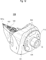
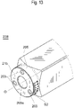
- Figs. 12 and 13 are perspective views depicting a head portion 10B and a shank 20B of the cutting tool of Embodiment 2 respectively.
- Fig. 12 is a perspective view when the head portion 10B is viewed from the rear side
- Fig. 13 is a perspective view when the shank 20B is viewed from the front side (front end side).
- configuration of the head portion 10 and the shank 20 described in Embodiment 1 are modified, and the other configurations and functions are the same as Embodiment 1. Therefore, a composing element the same as the head portion 10 or the shank 20 described in Embodiment 1 is denoted with the same reference sign as Embodiment 1, and description thereof is omitted.
- the concave portions 107 and the convex portions 207 described in Embodiment 1 are not disposed in the connecting portion (connecting surface 11b illustrated in Fig. 12 , and front end face 21b illustrated in Fig. 13 ) between the head portion 10B and the shank 20B in Embodiment 2.
- the angle of the head portion 10B can be adjusted freely within a movable range of the radial rake angle.
- a finer angle adjustment can be performed.
- the scale scale (scales S1 and S2) are formed in the head portion 10B and the shank 20B, just like Embodiment 1, hence the adjusted angle can be confirmed.
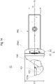
- Figs. 14 to 16 are diagrams depicting a configuration of a cutting tool 1C of Embodiment 3.
- Fig. 14 is a front view when the cutting tool 1C of Embodiment 3 is viewed in the same direction as Fig. 2 .
- Fig. 15 is a right side view when a head portion 10C is viewed in the same direction as Fig. 6 .
- Fig. 16 is a left side view when a shank 20C is viewed in the same direction as Fig. 9 .
- the cutting tool 1C head portion 10C and shank 20C illustrated in Figs.
- Embodiment 1 the shape of the connecting portion between the head portion 10 and the shank 20 described in Embodiment 1 is modified, and the other configurations and functions are the same as Embodiment 1. Therefore, a composing element the same as Embodiment 1 is denoted with a same reference sign as Embodiment 1, and description thereof is omitted.
- a diameter of the connecting portion between the head portion 10C and the shank 20C is enlarged.
- an outer diameter D1 of the connecting surface 11c and the front end face 21c, where the head portion 10C and the shank 20C are connected is larger than the outer diameter D2 ( Fig. 14 ) of the shank 20C.
- the pitch of the concave portions 107c formed on the peripheral area of the connecting surface 11c of the head portion 10C can be finer than the configuration of Embodiment 1.
- Embodiment 3 while the concave portions 107c in Embodiment 3 can be formed at the smaller angle ⁇ c ( Fig. 15 ) than ⁇ ( Fig. 6 ) in Embodiment 1.
- the angle can be more finely adjusted.
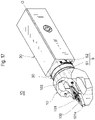
- Figs. 17 to 19 are diagrams depicting a configuration of a cutting tool 1D of Embodiment 4 respectively.
- Fig. 17 is a perspective view of the cutting tool 1D viewed from the front side.
- Fig. 18 is an exploded perspective view depicting the exploded state of the configuration of the cutting tool 1D.
- Figs. 19 is a diagram depicting a ring portion 30 in Figs. 17 and 18 .
- the configuration of the ring portion 30 is added to the head portion 10 and the shank 20 described in Embodiment 1, and the other configurations and functions are the same as Embodiment 1. Therefore, a composing element the same as the head portion 10 or the shank 20 described in Embodiment 1 is denoted with the same reference sign as Embodiment 1, and description thereof is omitted.
- the ring portion 30 is disposed between the head portion 10 and the shank 20 described in Embodiment 1.
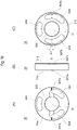
- Fig. 19(A) is a left side view of the ring portion 30 viewed from the front side
- Fig. 19(B) is a front view of the ring portion 30 viewed from the same direction as Fig. 2
- Fig. 19(C) is a right side view of the ring portion 30 viewed from the rear side.
- the ring portion 30 is formed approximately in a circular shape in the view in the center axis O direction.
- a through hole 305 to insert the male shaft 105 of the head portion 10 is formed.
- the male shaft 105 of the head portion 10 is inserted through this through hole 305 into the shaft hole 205a of the female shaft 205 of the shank 20, so as to connect the head portion 10 and the shank 20.
- Through holes 304 to insert the bolts 103 are formed on the peripheral area of the ring portion 30 at positions corresponding to the through holes 104 of the head portion 10.
- the head portion 10 and the shank 20 can be fixed via the ring portion 30.
- convex portions 307a (first engaging portions) are formed on a front end face 31a of the ring portion 30, and concave portions 307b (second engaging portions) are formed on a rear end face 31b of the ring portion 30.
- a plurality of concave portions 307b are formed on the peripheral area of the rear end face 31b along the circumferential direction at equal intervals.
- the convex portions 307a formed on the front end face 31a of the ring portion 30 are configured to be engageable with the plurality of concave portions 107 (engaging portions) formed on the connecting surface 11 of the head portion 10, and the plurality of concave portions 307b formed on the rear end face 31b of the ring portion 30 are configured to be engageable with the convex portions 207 (engaging portions) formed on the shank 20.
- the engagement between the plurality of concave portions 107 formed on the head portion 10 and the convex portions 307a of the ring portion 30 can be adjusted, so as to adjust the angle (engaging angle) of the head portion 10 with respect to the ring portion 30, and the engagement between the plurality of concave portions 307b formed on the ring portion 30 and the convex portions 207 of the shank 20 can be adjusted, so as to adjust the angle (engaging angle) of the shank 20 with respect to the ring portion 30, and as a result, the angle of the head portion 10 with respect to the shank 20 can be adjusted via the ring portion 30.
- the unit of the change of the engaging angle of the head portion 10 with respect to the ring portion 30 is different from the unit of the change of the engaging angle of the shank 20 with respect to the ring portion 30.
- the radial rake adjusting angle of the head portion 10 can be adjusted at 1° intervals.
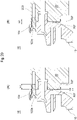
- Fig. 20 is a cross-sectional view depicting the configuration of the vicinity of a bolt of the cutting tool 1E of Embodiment 5.
- the configuration of the bolt 103e and the vicinity thereof is modified, and the other configurations and functions are the same as Embodiment 1. Therefore, a composing element the same as the head portion 10 or the shank 20 described in Embodiment 1 is denoted with the same reference sign as Embodiment 1, and description thereof is omitted.
- Fig. 20(A) indicates a state where a concave portion 107 of the head portion 10 and the convex portion 207 of the shank 20 are engaged
- Fig. 20(B) indicates a state where the engagement of the concave portion 107 of the head portion 10 and the convex portion 207 of the shank 20 is released.
- the length of the thread engagement L3 of the bolt 103e is larger than the height L1 of the convex portion 207.
- Figs. 21 to 23 are diagrams depicting the configuration of a cutting tool 1F of Embodiment 6.
- Fig. 21(A) is a front view when the cutting tool 1F of Embodiment 6 is viewed in the same direction as Fig. 2 .
- Fig. 21(B) is an enlarged view of a portion indicated by the broken line frame a in Fig. 21(A) .
- Fig. 22 is an exploded perspective view depicting the exploded state of the configuration of the cutting tool 1F in Fig. 21 diagonally viewed from the rear side.
- Fig. 23 is an exploded perspective view depicting the exploded state of the configuration of the cutting tool 1F in Fig. 21 diagonally viewed from the front side.
- the configuration of the scale of the cutting tool 1D of Embodiment 4 ( Figs. 17 and 18 ) is modified, and the other configurations and functions are the same as Embodiment 4. Therefore, a composing element the same as Embodiment 4 is denoted with the same reference sign as Embodiment 4, and description thereof is omitted.
- the interval ⁇ of the notches of the scale S2 of the head portion 10F ( Fig. 21(B) ) matches with the serration interval ⁇ of the concave portions 107 of the head portion 10F ( Fig. 22 ), and the interval ⁇ of the notches of the scale S2 is 5°, for example.
- the interval ⁇ d of the notches of the scale S3 of the ring portion 30F matches with the serration intervals ⁇ d of the concave portions 307b of the ring portion 30F ( Fig. 22 ), and the interval ⁇ d of the notches of the scale S3 is 4°, for example.
- the scale is not formed on the shank 20F, but is formed on the head portion 10F and the ring portion 30F respectively.
- the indication groove S1, to set the scale S2 is formed on the ring portion 30F (the head portion 10F side of the ring portion 30F).
Landscapes
- Engineering & Computer Science (AREA)
- Mechanical Engineering (AREA)
- Milling Processes (AREA)
Abstract
Description
- This application is based on
Japanese Patent Application No. 2019-127245 filed July 8, 2019 Japanese Patent Application No. 2019-163190 filed September 6, 2019 - The present invention relates to a cutting tool.
- As a cutting tool used for cutting processing of a work material, such as metal, a cutting tool disclosed in
Patent Document 1 is known. - In
Patent Document 1, a cutting tool including a head (main body 3) and aholder 2, which is connected to the back side of themain body 3, is disclosed. In the front portion of themain body 3, a seat portion 4 (insert mounting seat) for a cutting insert is provided. Themain body 3 is also provided with a male shaft 6 which extends backward from the rear end portion of themain body 3. When themain body 3 is connected to theholder 2, this male shaft 6 is inserted into a seat 7 inside theholder 2, whereby the position of themain body 3, with respect to theholder 2, is fixed. - Patent Document 1:
WO1999/039852 - In the configuration of
Patent Document 1, the mounting orientation of the cutting insert, installed in the insert mounting seat when the head is installed in the holder, is fixed. Therefore, when a helical flute is processed around a round bar, for example, by using the cutting tool ofPatent Document 1, only one type of helical flute can be processed, and a helical flute having a different lead (length that is advanced by one rotation) cannot be processed. In other words, each time when a helical flute having a different lead is processed using the cutting tool ofPatent Document 1, a different tool is needed, which may increase the component storage cost. - With the foregoing in view, it is an object of the present invention to provide a cutting tool that can process helical flutes having different leads by using one tool, so as to reduce the component storage cost.
- A cutting tool according to an aspect of the present invention is a cutting tool extending along a center axis and including on a front end side a cutting insert to cut a work material, the cutting tool including: a head portion which includes an insert mounting seat, on which the cutting insert is installed, on a front end side; a holder which is installed on a rear end side of the head portion and holds the head portion; and a fixing member which fixes a position of the head portion with respect to the holder when the head portion is mounted on the holder. The head portion is configured to be mountable on the holder, with an angle thereof changing around the center axis.
- According to the above aspect, the cutting tool is fixed to the holder using the fixing member, with the angle of the head portion changing around the center axis, so as to maintain this state. Thereby the radial rake angle of the cutting insert disposed in the head portion can be changed. This makes it possible to process the helical flutes at different radial rake angles using one type of cutting insert. As a result, different helical flutes can be processed using one tool, and the component storage cost can be reduced.
- In the above aspect, the head portion may include an engaging portion, constituted of a concave portion and/or a convex portion, on a connecting surface of the head portion that is connected to the holder, and the holder may include an engaged portion, constituted of a convex portion and/or a concave portion engaging with the engaging portion, on a surface of the holder that is connected to the head portion.
- In the above aspect, the concave portion may be provided in plurality and formed on a peripheral area of the connecting surface in a circumferential direction.
- In the above aspect, the concave portion may be formed at symmetric positions across the center axis.
- In the above aspect, at least one of the head portion and the holder may have a scale, and a rotation angle of the head portion may be adjustable by setting with the scale.
- In the above aspect, a ring portion may be further included, and on one end face of the ring portion, a first engaging portion, which engages with the engaging portion of the head portion, may be disposed, and on the other end face of the ring portion, a second engaging portion, which engages with the engaging portion of the holder, may be disposed, the head portion is configured to be engageable with the ring portion, with an angle thereof changing around the center axis, the holder may be configured to be engageable with a ring portion, with an angle thereof changing around the center axis, and the unit of change of the engaging angle of the head portion with respect to the ring portion may be different from the unit of change of the engaging angle of the holder with respect to the ring portion.
- In the above aspect, the engaging portion of the holder may be constituted of at least one convex portion, the second engaging portion of the ring portion may be constituted of a plurality of grooves with which the convex portion of the engaging portion of the holder engages, the first engaging portion of the ring portion may be constituted of at least one convex portion, and the engaging portion of the head portion may be constituted of a plurality of grooves with which the convex portion of the first engaging portion of the ring portion engages.
- At least one of the head portion and the ring portion may have a scale corresponding to the unit of change of the engaging angle of the head portion with respect to the ring portion, at least one of the ring portion and the holder may have a scale corresponding to the unit of change of the engaging angle of the holder with respect to the ring portion, and a rotation angle of the head portion may be adjustable by setting with the scale.
- According to the present invention, a cutting tool, which can process helical flutes having different leads using one tool, so as to reduce the component storage cost, can be provided.
-
-
Fig. 1 is a perspective view depicting a cutting tool ofEmbodiment 1. -
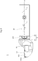
Fig. 2 is a front view depicting the cutting tool illustrated inFig. 1 viewed in the arrow A1 direction. -
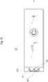
Fig. 3 is a plan view depicting the cutting tool illustrated inFig. 1 viewed in the arrow A2 direction. -
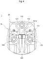
Fig. 4 is a left side view depicting the cutting tool illustrated inFig. 1 viewed in the arrow A3 direction. -
Fig. 5 is a perspective view depicting a head portion illustrated inFig. 1 viewed from the rear side. -
Fig. 6 is a right side view depicting the head portion illustrated inFig. 5 viewed in the arrow B1 direction. -
Fig. 7 is a front view depicting the head portion illustrated inFig. 5 viewed in the arrow B2 direction. -
Fig. 8 is a perspective view depicting a shank illustrated inFig. 1 viewed from the front end side. -
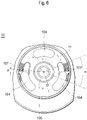
Fig. 9 is a left side view depicting the shank illustrated inFig. 8 viewed in the arrow C1 direction. -
Fig. 10 is a front view depicting the shank illustrated inFig. 8 viewed in the arrow C2 direction. -
Fig. 11 is an enlarged view depicting a region including concave portions and a convex portion when the head portion and the shank are connected. -
Fig. 12 is a perspective view depicting a head portion of a cutting tool ofEmbodiment 2 viewed from the rear side. -
Fig. 13 is a perspective view depicting a shank of the cutting tool ofEmbodiment 2 viewed from the front end side. -
Fig. 14 is a front view depicting a cutting tool of Embodiment 3. -
Fig. 15 is a right side view depicting a head portion of the cutting tool inFig. 14 . -
Fig. 16 is a left side view depicting a shank of the cutting tool inFig. 14 . -
Fig. 17 is a perspective view depicting a cutting tool of Embodiment 4. -
Fig. 18 is an exploded perspective view depicting an exploded state of the configuration of the cutting tool inFig. 17 . -
Fig. 19 is a diagram depicting a configuration of a ring portion of the cutting tool inFig. 17 . -
Fig. 20 is a cross-sectional view depicting a configuration of vicinity of a bolt of the cutting tool of Embodiment 5. -
Figs. 21 is a diagram depicting a configuration of a cutting tool of Embodiment 6. -
Fig. 22 is an exploded perspective view depicting an exploded state of the configuration of the cutting tool inFig. 21 viewed diagonally from the rear side. -
Fig. 23 is an exploded perspective view depicting an exploded view of the configuration of the cutting tool inFig. 21 viewed diagonally from the rear side. - Embodiments of the present invention will be described with reference to the accompanying drawings. In some cases, the dimensions, shapes, angles, and the like of the drawings may be different from the actual dimensions, shapes, angles, and the like. Therefore, the technical scope of the present invention is not limited to the dimensions, shapes, angles, and the like of each component indicated in the drawings.
- A configuration of a
cutting tool 1 according toEmbodiment 1 will be described with reference toFigs. 1 to 10 . Thiscutting tool 1 is a turning tool that rotates a work material to process it without rotating the tool.Figs. 1 to 4 are diagrams illustrating the configuration of thecutting tool 1.Figs. 5 to 7 are diagrams illustrating a configuration of ahead portion 10.Figs. 8 to 10 are diagrams illustrating a configuration of a shank (holder) 20. - The
cutting tool 1 includes theshank 20, which extends along the center axis O, and ahead portion 10. Thehead portion 10 is connected to theshank 20 on the front end side (left side inFig. 2 ). - The
head portion 10 has aninsert mounting seat 102 on the front end side thereof, and acutting insert 101 is mounted on theinsert mounting seat 102. The cuttinginsert 101 is removably installed on theinsert mounting seat 102. InEmbodiment 1, the cuttinginsert 101 is installed in theinsert mounting seat 102, so that acutting edge 101a of the cuttinginsert 101 protrudes (left side inFig. 2 ) from the front end of thehead portion 10. The portion of thecutting edge 101a protruding from thehead portion 10 is used for cutting processing. Theshank 20 and thehead portion 10 may be connected such that the tip of thecutting edge 101a of the cuttinginsert 101 is positioned on the axial line of the center axis O (that is, the center axis of theshank 20 and the center axis of thehead portion 10 are on the same axis) in the top view (Fig. 3 ). The cuttinginsert 101 ofEmbodiment 1 is an approximately square-shaped insert in the top view (Fig. 3 ), but the present invention is not limited to the above mode, and the shape of the cuttinginsert 101 may be selected appropriately, so as to match with the shape of the helical flutes (e.g., screw shape, groove shape) to be processed. - A
male shaft 105 is disposed on the rear end side of thehead portion 10 at the center area thereof, as illustrated inFigs. 5 to 7 . Themale shaft 105 is disposed so as to protrude backward (right direction inFig. 2 orFig. 7 ) from the center area of the rear end face 11 (connectingsurface 11 of thehead portion 10 to be connected to the shank 20) of thehead portion 10 in the extending direction of the center axis O (hereafter "axial direction"). Themale shaft 105 has an approximately cylindrical shape with the center axis O as the center. Themale shaft 105 is disposed so that themale shaft 105 is inserted into ashaft hole 205a of afemale shaft 205 disposed on theshank 20 when thehead portion 10 is installed in theshank 20. Throughholes 104, to whichbolts 103 are inserted, are formed in thehead portion 10 in the axial direction. When thehead portion 10 is installed in theshank 20, thebolts 103 are inserted into the throughholes 104 formed in thehead portion 10, and tightened to the bolt fastening holes 203 of theshank 20, whereby the position of thehead portion 10 with respect to theshank 20 is fixed. InEmbodiment 1, a shape of each throughhole 104, to which eachbolt 103 is inserted, is a long hole of which major axis is bent in a circular-arc shape when thehead portion 10 is viewed from the rear side, and is formed on the peripheral area of the connectingsurface 11 in the circumferential direction. By forming each throughhole 104 in this way, when the angle of thehead portion 10 is changed around the center axis O, thebolt 103 can be inserted into the throughhole 104 in the state after the angle is changed. Thereby thehead portion 10 and theshank 20 can be fixed in the state after the rotation angle of thehead portion 10 is adjusted. InEmbodiment 1, the modes of eachbolt 103 and eachbolt fastening hole 203 are not especially limited, and, for example, thebolt 103 may have a shaft portion in which a male screw is formed, and be screwed into thebolt fastening hole 203 in which a female screw is formed. - The
shank 20 is a member to hold thehead portion 10, and is connected on the rear end side of thehead portion 10. Theshank 20 is extended such that the longitudinal direction thereof is along the center axis O, and has an approximately rectangular parallelepiped shape. As illustrated inFig. 8 , theshank 20 has afemale shaft 205 on the front end side thereof, so as to install thehead portion 10. Thefemale shaft 205 has an approximately cylindrical shape, and theshaft hole 205a, to insert themale shaft 105 of thehead portion 10, is formed at the center area thereof. Thebolt fastening hole 203, to fasten and fix thebolt 103, is formed at each position in thefemale shaft 205 corresponding to each throughhole 104 of thehead portion 10. Thebolt fastening hole 203 is formed at a plurality of positions on the front end face 21 of theshank 20 in the circumferential direction at equal intervals. - In the illustrated example, the
shank 20 has an approximately rectangular parallelepiped shape, but the present invention is not limited to this example, and may have an approximately cylindrical shape or any other shape, for example, as long as theshank 20 is a member that is connected to thehead portion 10 and has a function to hold thehead portion 10. Themale shaft 105 and thefemale shaft 205 are also not limited to the modes in the illustrations, and the shape, size, or the like thereof may be changed, as long as thehead portion 10 and theshank 20 can be connected in the state after the rotation angle of thehead portion 10 is adjusted. - In
Embodiment 1, a number of bolts 103 (fixing members) and a number of bolt fastening holes 203, to which thebolts 103 are inserted, are 3 respectively, but the present invention is not limited to this example, and may be a number ofbolts 103 or bolt fastening holes 203 to fix thehead portion 10 and theshank 20 may be 1, 2 or 4 or more. Further, inEmbodiment 1, thebolt 103 is used as an example of the fixing member, but a different member may be used as the fixing member, as long as the member can fix the position of thehead portion 10 with respect to theshank 20. - According to
Embodiment 1, thehead portion 10 is configured to be mountable on theshank 20 with changing the angle around the center axis O. In other words, thehead portion 10 can be fixed to theshank 20 in the state after the relative angle (rotational angle around the center axis O) of thehead portion 10 with respect to theshank 20 is adjusted. The angle adjustment mechanism of thehead portion 10 with respect to theshank 20 will now be described. - As illustrated in
Figs. 5 and6 , a plurality ofconcave portions 107 are formed on the connectingsurface 11, which is connected to theshank 20, of thehead portion 10, and theconcave portions 107 are engaged with theconvex portions 207 of theshank 20 when thehead portion 10 is installed in theshank 20. By this engagement of theconcave portions 107 formed on the rear end face 11 of thehead portion 10 and theconvex portions 207 formed on the front end face 21 of theshank 20, the position of thehead portion 10 with respect to theshank 20 is adjusted, and the orientation thereof (mounting orientation of the cuttinginsert 101 installed on the front end of the head portion 10) can be held. As described above, the position of thehead portion 10 with respect to theshank 20 is fixed by fastening thebolts 103. - The connecting
surface 11 has an approximately circular shape in the side view (when thehead portion 10 is viewed from the rear end side, as illustrated inFig. 6 ), and a plurality ofconcave portions 107 are formed on the peripheral area of the connectingsurface 11 in the circumferential direction at equal intervals. Since a plurality ofconcave portions 107 are formed, the rotation angle of thehead portion 10 with respect to theshank 20 can be adjusted in multiple steps. InEmbodiment 1, theconcave portions 107 are formed in the peripheral area of the connectingsurface 11 in the circumferential direction at 5° intervals, and theconcave portions 107 as a whole can adjust the rotation angle of thehead portion 10 in a -20° ≤ α ≤ 20° range, that is, in a ±20° range around the center axis O. - In this way, the radial rake angle of the cutting
insert 101 disposed in thehead portion 10 can be changed by changing the angle of thehead portion 10 around the center axis O, and fixing theshank 20 and thehead portion 10 by fastening thebolts 103 such that this changed state can be maintained. Thereby, processing at different radial rake angles can be implemented using one type of cuttinginsert 101. In concrete terms, as illustrated inFigs. 1 and2 , for example, in a case where a reference position (radial rake angle of the cuttinginsert 101 is 0°) is a position where thehead portion 10 is installed in the shank 20 (theconcave portions 107 are engaged with the convex portions 207), such that an indication groove S1 of thehead portion 10 is set to the position indicting 0° of the scale S2 of theshank 20, thehead portion 10 can be installed in theshank 20 to perform cutting processing in a state after the radial rake angle of the cuttinginsert 101 is adjusted in a positive direction or a negative direction (-20° ≤ α ≤ 20°) from the reference position. Since processing at a different radial rake angle is possible, different helical flutes having different leads can be processed using one tool, whereby the component storage cost can be reduced. - In the illustration examples, the
concave portions 107 formed on the connectingsurface 11 of thehead portion 10 are formed at symmetric positions with respect to the center axis O in the -20° ≤ α ≤ 20° range (Fig. 6 ) at 5° intervals. Theconvex portions 207 that engages with theconcave portions 107 are formed at symmetric positions with respect to the center axis O. However, the present invention is not limited to this example, where theconcave portions 107 and theconvex portions 207 are at symmetric positions with respect to the center axis O. For example, a plurality ofconcave portions 107 may be disposed at one location on the peripheral area of the connectingsurface 11, and oneconvex portion 207 that engages with theconcave portions 107 may be disposed, whereby the angle of thehead portion 10 can be adjusted around the center axis O. Further, theconcave portions 107 may be disposed at 3 or more locations on the peripheral area of the connectingsurface convex portions 207 may be disposed so as to correspond to theconcave portions 107. In other words, the positions and numbers of theconcave portions 107 and theconvex portions 207 may be changed, as long as thehead portion 10 can be installed in theshank 20 with changing the angle around the center axis O. - According to
Embodiment 1, the scale S (indication groove S1 of thehead portion 10 and scale S2 of the shank 20) that allow to visually recognize the adjusted angle of thehead portion 10 are formed on the outer peripheral surface of thefemale shaft 205 disposed on the front end side of theshank 20. By setting the indication groove S1 to the scale S2 of theshank 20, thehead portion 10 can be accurately set to an arbitrary angle compared with the configuration without the scale, and the angle can be easily adjusted. InEmbodiment 1, the notches of the scale S2 are formed at 5° intervals, but the notches of the scale (interval of the notches) may be arbitrarily set in accordance with the adjustment angle of thehead portion 10. -
Fig. 11 is an enlarged view depicting a region including theconcave portions 107 and theconvex portion 207 when thehead portion 10 and theshank 20 are connected. As illustrated inFig. 11 , theconvex portion 207 formed in theshank 20 has a cone-shaped cross-section, protruding from the front end face 21 of theshank 20 toward the front side in the axial direction (left side inFigs. 10 and11 ). An angle θg formed by the extended lines (broken lines inFig. 11 ) of the sides of theconvex portion 207 is set to 60°, for example. Eachconcave portion 107 formed on the rear end face 11 of thehead portion 10 has a concave shape along the outer edge of theconvex portion 207, and is preferably concave from the rear end face 11 of thehead portion 10, so as to position along the outer edge of theconvex portion 207 with a gap G. In other words, there is a gap G, as illustrated inFig. 11 , between the ridge of theconvex portion 207 and the groove of theconcave portion 107. When thehead portion 10 and theshank 20 are installed, the position of thehead portion 10 is fixed by fastening thebolt 103 in the state of maintaining the gap G in this way. By this configuration, theconvex portion 207 and theconcave portion 107 can be prevented from contacting with each other each time thehead portion 10 is installed in theshank 20 with changing the angle around the center axis O, and, as a result, abrasion between theconcave portion 107 and theconvex portion 207 can be suppressed. - In
Embodiment 1 described above, the concave portion 107 (engaging portion) is disposed in thehead portion 10, and the convex portion 207 (engaged portion) is disposed in theshank 20, in order to adjust the angle of thehead portion 10 around the center axis O, but a reverse configuration (in other words, the convex portion (engaging portion) is disposed in thehead portion 10, and the concave portion 107 (engaged portion) is disposed in the shank 20) may be used. - Further, in
Embodiment 1 described above, theconcave portions 107 are disposed in thehead portion 10, and theconvex portions 207 are disposed in theshank 20, and at the same time, the scale S (indication groove S1 of thehead portion 10 and scale S2 of the shank 20) are disposed to visually recognize the adjusted angle of thehead portion 10, but only theconcave portions 107 and theconvex portions 207 may be disposed without disposing the scale S. Thereby the angle of thehead portion 10 can easily be adjusted in accordance with the shapes of theconcave portions 107 and theconvex portions 207, which are formed at a predetermined interval in advance. By disposing theconcave portions 107 and the convex portions 207 (that is, a configuration with serration operability to adjust the angle improves, and operation time can be decreased. -
Figs. 12 and13 are perspective views depicting ahead portion 10B and ashank 20B of the cutting tool ofEmbodiment 2 respectively.Fig. 12 is a perspective view when thehead portion 10B is viewed from the rear side, andFig. 13 is a perspective view when theshank 20B is viewed from the front side (front end side). In thehead portion 10B and theshank 20B illustrated inFigs. 12 and13 , configuration of thehead portion 10 and theshank 20 described inEmbodiment 1 are modified, and the other configurations and functions are the same asEmbodiment 1. Therefore, a composing element the same as thehead portion 10 or theshank 20 described inEmbodiment 1 is denoted with the same reference sign asEmbodiment 1, and description thereof is omitted. - As illustrated in
Figs. 12 and13 , theconcave portions 107 and theconvex portions 207 described inEmbodiment 1 are not disposed in the connecting portion (connectingsurface 11b illustrated inFig. 12 , andfront end face 21b illustrated inFig. 13 ) between thehead portion 10B and theshank 20B inEmbodiment 2. Thereby the angle of thehead portion 10B can be adjusted freely within a movable range of the radial rake angle. Compared with the configuration including theconcave portions 107 and theconvex portions 207 described inEmbodiment 1, a finer angle adjustment can be performed. InEmbodiment 2, the scale (scales S1 and S2) are formed in thehead portion 10B and theshank 20B, just likeEmbodiment 1, hence the adjusted angle can be confirmed. -
Figs. 14 to 16 are diagrams depicting a configuration of acutting tool 1C ofEmbodiment 3.Fig. 14 is a front view when thecutting tool 1C ofEmbodiment 3 is viewed in the same direction asFig. 2 .Fig. 15 is a right side view when ahead portion 10C is viewed in the same direction asFig. 6 .Fig. 16 is a left side view when ashank 20C is viewed in the same direction asFig. 9 . In thecutting tool 1C (head portion 10C andshank 20C) illustrated inFigs. 14 to 16 , the shape of the connecting portion between thehead portion 10 and theshank 20 described inEmbodiment 1 is modified, and the other configurations and functions are the same asEmbodiment 1. Therefore, a composing element the same asEmbodiment 1 is denoted with a same reference sign asEmbodiment 1, and description thereof is omitted. - As illustrated in
Figs. 14 to 16 , inEmbodiment 3, a diameter of the connecting portion between thehead portion 10C and theshank 20C is enlarged. Specifically, an outer diameter D1 of the connectingsurface 11c and thefront end face 21c, where thehead portion 10C and theshank 20C are connected, is larger than the outer diameter D2 (Fig. 14 ) of theshank 20C. Thereby the pitch of theconcave portions 107c formed on the peripheral area of the connectingsurface 11c of thehead portion 10C can be finer than the configuration ofEmbodiment 1. In other words, theconcave portions 107 inEmbodiment 1 are formed in the peripheral area of the connectingsurface 11 in the circumferential direction at θ = 5° intervals (Fig. 6 ), while theconcave portions 107c inEmbodiment 3 can be formed at the smaller angle θc (Fig. 15 ) than θ (Fig. 6 ) inEmbodiment 1. By engaging theconcave portions 107c formed like this and theconvex portions 207c on thefront end face 21c of the shank 20c to adjust the angle of thehead portion 10C, the angle can be more finely adjusted. -
Figs. 17 to 19 are diagrams depicting a configuration of acutting tool 1D of Embodiment 4 respectively.Fig. 17 is a perspective view of thecutting tool 1D viewed from the front side.Fig. 18 is an exploded perspective view depicting the exploded state of the configuration of thecutting tool 1D.Figs. 19 is a diagram depicting aring portion 30 inFigs. 17 and18 . In thecutting tool 1D illustrated inFigs. 17 to 19 , the configuration of thering portion 30 is added to thehead portion 10 and theshank 20 described inEmbodiment 1, and the other configurations and functions are the same asEmbodiment 1. Therefore, a composing element the same as thehead portion 10 or theshank 20 described inEmbodiment 1 is denoted with the same reference sign asEmbodiment 1, and description thereof is omitted. - As illustrated in
Figs. 17 and18 , in Embodiment 4, thering portion 30 is disposed between thehead portion 10 and theshank 20 described inEmbodiment 1. -
Fig. 19(A) is a left side view of thering portion 30 viewed from the front side,Fig. 19(B) is a front view of thering portion 30 viewed from the same direction asFig. 2 , andFig. 19(C) is a right side view of thering portion 30 viewed from the rear side. - The
ring portion 30 is formed approximately in a circular shape in the view in the center axis O direction. At the center of thering portion 30, a throughhole 305, to insert themale shaft 105 of thehead portion 10, is formed. Themale shaft 105 of thehead portion 10 is inserted through this throughhole 305 into theshaft hole 205a of thefemale shaft 205 of theshank 20, so as to connect thehead portion 10 and theshank 20. Throughholes 304 to insert thebolts 103 are formed on the peripheral area of thering portion 30 at positions corresponding to the throughholes 104 of thehead portion 10. By fastening thebolts 103, inserted into the throughholes 104 of thehead portion 10, in thebolt fastening hole 203 of theshank 20 via the throughhole 304 of the ring portion 30 (seeFig. 8 and the like), thehead portion 10 and theshank 20 can be fixed via thering portion 30. - As illustrated in
Fig. 19 ,convex portions 307a (first engaging portions) are formed on afront end face 31a of thering portion 30, andconcave portions 307b (second engaging portions) are formed on arear end face 31b of thering portion 30. A plurality ofconcave portions 307b are formed on the peripheral area of therear end face 31b along the circumferential direction at equal intervals. Theconvex portions 307a formed on thefront end face 31a of thering portion 30 are configured to be engageable with the plurality of concave portions 107 (engaging portions) formed on the connectingsurface 11 of thehead portion 10, and the plurality ofconcave portions 307b formed on therear end face 31b of thering portion 30 are configured to be engageable with the convex portions 207 (engaging portions) formed on theshank 20. Because of this configuration, the engagement between the plurality ofconcave portions 107 formed on thehead portion 10 and theconvex portions 307a of thering portion 30 can be adjusted, so as to adjust the angle (engaging angle) of thehead portion 10 with respect to thering portion 30, and the engagement between the plurality ofconcave portions 307b formed on thering portion 30 and theconvex portions 207 of theshank 20 can be adjusted, so as to adjust the angle (engaging angle) of theshank 20 with respect to thering portion 30, and as a result, the angle of thehead portion 10 with respect to theshank 20 can be adjusted via thering portion 30. The unit of the change of the engaging angle of thehead portion 10 with respect to thering portion 30 is different from the unit of the change of the engaging angle of theshank 20 with respect to thering portion 30. For example, theconcave portions 107 of thehead portion 10 are formed on the peripheral area of the connectingsurface 11 in the circumferential direction at θ = 5° intervals (Fig. 6 ), and theconcave portion 307b of thering portion 30 are formed on the peripheral area of therear end face 31b in the circumferential direction at θd = 4° intervals (Fig. 19(C) ). By adjusting the respective angles via thering portion 30, the radial rake adjusting angle of thehead portion 10 can be adjusted at 1° intervals. -
Fig. 20 is a cross-sectional view depicting the configuration of the vicinity of a bolt of thecutting tool 1E of Embodiment 5. In thecutting tool 1E of Embodiment 5, the configuration of thebolt 103e and the vicinity thereof is modified, and the other configurations and functions are the same asEmbodiment 1. Therefore, a composing element the same as thehead portion 10 or theshank 20 described inEmbodiment 1 is denoted with the same reference sign asEmbodiment 1, and description thereof is omitted. -
Fig. 20(A) indicates a state where aconcave portion 107 of thehead portion 10 and theconvex portion 207 of theshank 20 are engaged, andFig. 20(B) indicates a state where the engagement of theconcave portion 107 of thehead portion 10 and theconvex portion 207 of theshank 20 is released. In Embodiment 5, the length of the thread engagement L3 of thebolt 103e is larger than the height L1 of theconvex portion 207. Thereby even in the state where the engagement of theconcave portion 107 and theconvex portion 207 is released (Fig. 20(B) ), thebolt 103e can maintain the fastened state with thebolt fastening hole 203. As a result, the radial rake adjustment of thehead portion 10 can be performed merely by loosening thebolt 103e without completely removing thebolt 103e. -
Figs. 21 to 23 are diagrams depicting the configuration of acutting tool 1F of Embodiment 6.Fig. 21(A) is a front view when thecutting tool 1F of Embodiment 6 is viewed in the same direction asFig. 2 .Fig. 21(B) is an enlarged view of a portion indicated by the broken line frame a inFig. 21(A) .Fig. 22 is an exploded perspective view depicting the exploded state of the configuration of thecutting tool 1F inFig. 21 diagonally viewed from the rear side.Fig. 23 is an exploded perspective view depicting the exploded state of the configuration of thecutting tool 1F inFig. 21 diagonally viewed from the front side. In thecutting tool 1F of Embodiment 6, the configuration of the scale of thecutting tool 1D of Embodiment 4 (Figs. 17 and18 ) is modified, and the other configurations and functions are the same as Embodiment 4. Therefore, a composing element the same as Embodiment 4 is denoted with the same reference sign as Embodiment 4, and description thereof is omitted. The interval θ of the notches of the scale S2 of thehead portion 10F (Fig. 21(B) ) matches with the serration interval θ of theconcave portions 107 of thehead portion 10F (Fig. 22 ), and the interval θ of the notches of the scale S2 is 5°, for example. The interval θd of the notches of the scale S3 of thering portion 30F (Fig. 21(B) ) matches with the serration intervals θd of theconcave portions 307b of thering portion 30F (Fig. 22 ), and the interval θd of the notches of the scale S3 is 4°, for example. - In the
cutting tool 1F of Embodiment 6, as illustrated inFigs. 21 to 23 , the scale is not formed on theshank 20F, but is formed on thehead portion 10F and thering portion 30F respectively. Specifically, the scale S2 is formed in thehead portion 10F at θ = 5° intervals, and the indication groove S1, to set the scale S2, is formed on thering portion 30F (thehead portion 10F side of thering portion 30F). The scale S3 is formed on theshank 20F side of thering portion 30F at θd = 4° intervals, and an indication groove S1, to set the scale S3, is formed in theshank 20F. By forming the scale S2 in thehead portion 10F at θ = 5° intervals, and forming the indication groove S1, to set the scale S2, on thering portion 30F, thehead portion 10F can be easily adjusted with respect to thering portion 30F at 5° intervals. Further, by forming the scale S3 in thering portion 30F at θd = 4° intervals, and forming the indication groove S1 on theshank 20F, theshank 20F can be easily adjusted with respect to thering portion 30F at 4° intervals. By combining the angle adjustment of thering portion 30F and the angle adjustment of thehead portion 10 configured in this way, the radial rake adjusting angle of thehead portion 10 can be adjusted at 1° intervals, and finer angle adjustment can be performed. - The embodiments described above are for assisting understanding of the present invention, and are not intended to limit the interpretation of the present invention. The flow chart and sequence described in the embodiments, each composing element of the embodiments, and positions, materials, conditions, shapes, sizes, and the like thereof described in the embodiments are not limited to the examples, but may be modified as required. The configurations described in different embodiments may be partially replaced or combined.
-
- 1
- Cutting tool
- 10
- Head portion
- 11
- Connecting surface
- 20
- Shank (holder)
- 101
- Cutting insert
- 102
- Insert mounting seat
- 107
- Concave portion
- 207
- Convex portion
- S1, S2
- Scale
Claims (8)
- A cutting tool extending along a center axis, and including on a front end side a cutting insert to cut a work material, the cutting tool comprising:a head portion which includes an insert mounting seat, on which the cutting insert is installed, on a front end side;a holder which is installed on a rear end side of the head portion and holds the head portion; anda fixing member which fixes a position of the head portion with respect to the holder when the head portion is mounted on the holder, whereinthe head portion is configured to be mountable on the holder, with an angle thereof changing around the center axis.
- The cutting tool according to claim 1, whereinthe head portion includes an engaging portion, constituted of a concave portion and/or a convex portion, on a connecting surface of the head portion that is connected to the holder, andthe holder includes an engaged portion, constituted of a convex portion and/or a concave portion engaging with the engaging portion, on a surface of the holder that is connected to the head portion.
- The cutting tool according to claim 2, wherein the concave portion is provided in plurality and formed on a peripheral area of the connecting surface in a circumferential direction.
- The cutting tool according to claim 2 or 3, wherein the concave portion and the convex portion are formed at symmetric positions across the center axis.
- The cutting tool according to any one of claims 1 to 4, whereinat least one of the head portion and the holder has a scale, anda rotation angle of the head portion is adjustable by setting with the scale.
- The cutting tool according to claim 1, further comprising a ring portion, whereinon one end face of the ring portion, a first engaging portion, which engages with the engaging portion of the head portion, is disposed, and on the other end face of the ring portion, a second engaging portion, which engages with the engaging portion of the holder, is disposed,the head portion is configured to be engageable with the ring portion, with an angle thereof changing around the center axis,the holder is configured to be engageable with the ring portion, with an angle thereof changing around the center axis, andthe unit of change of the engaging angle of the head portion with respect to the ring portion is different from the unit of change of the engaging angle of the holder with respect to the ring portion.
- The cutting tool according to claim 6, whereinthe engaging portion of the holder is constituted of at least one convex portion,the second engaging portion of the ring portion is constituted of a plurality of grooves with which the convex portion of the engaging portion of the holder engages,the first engaging portion of the ring portion is constituted of at least one convex portion, andthe engaging portion of the head portion is constituted of a plurality of grooves with which the convex portion of the first engaging portion of the ring portion engages.
- The cutting tool according to claim 6 or 7, whereinat least one of the head portion and the ring portion has a scale corresponding to the unit of change of the engaging angle of the head portion with respect to the ring portion,at least one of the ring portion and the holder has a scale corresponding to the unit of change of the engaging angle of the holder with respect to the ring portion, anda rotation angle of the head portion is adjustable by setting with the scale.
Applications Claiming Priority (3)
| Application Number | Priority Date | Filing Date | Title |
|---|---|---|---|
| JP2019127245 | 2019-07-08 | ||
| JP2019163190A JP7341805B2 (en) | 2019-07-08 | 2019-09-06 | Cutting tools |
| PCT/JP2020/026273 WO2021006221A1 (en) | 2019-07-08 | 2020-07-03 | Cutting tool |
Publications (4)
| Publication Number | Publication Date |
|---|---|
| EP3998129A1 true EP3998129A1 (en) | 2022-05-18 |
| EP3998129A4 EP3998129A4 (en) | 2023-07-26 |
| EP3998129B1 EP3998129B1 (en) | 2025-04-09 |
| EP3998129C0 EP3998129C0 (en) | 2025-04-09 |
Family
ID=74114230
Family Applications (1)
| Application Number | Title | Priority Date | Filing Date |
|---|---|---|---|
| EP20837611.1A Active EP3998129B1 (en) | 2019-07-08 | 2020-07-03 | Cutting tool |
Country Status (4)
| Country | Link |
|---|---|
| US (1) | US12083604B2 (en) |
| EP (1) | EP3998129B1 (en) |
| CN (1) | CN114025903A (en) |
| WO (1) | WO2021006221A1 (en) |
Families Citing this family (2)
| Publication number | Priority date | Publication date | Assignee | Title |
|---|---|---|---|---|
| CN112809062A (en) * | 2021-02-02 | 2021-05-18 | 游蜜 | Planing tool for tool withdrawal of grinding wheel |
| JP7788094B1 (en) * | 2025-09-03 | 2025-12-18 | 株式会社タンガロイ | Tool body and cutting tool including same |
Family Cites Families (23)
| Publication number | Priority date | Publication date | Assignee | Title |
|---|---|---|---|---|
| DE1552373A1 (en) * | 1966-01-21 | 1969-09-11 | Rolf Maier | Boring bar with fine adjustment device |
| US3480287A (en) * | 1967-03-14 | 1969-11-25 | Donnell James E O | Boring tool head |
| JPS5848002Y2 (en) | 1976-05-11 | 1983-11-01 | サンドヴィク・アクチ−ボラ−グ | Boring rod insertion material |
| JPS5914117Y2 (en) * | 1977-05-23 | 1984-04-25 | 富士精工株式会社 | Quick-change cutting tool mounting device |
| EP0101917B1 (en) | 1982-07-30 | 1986-05-28 | Gerhard Rall | Cutting tool |
| DE3243948A1 (en) * | 1982-11-27 | 1984-07-05 | Gerhard 7142 Marbach Rall | Separable tool for machining |
| DE3228521C2 (en) * | 1982-07-30 | 1986-11-20 | Günther Hertel | Tool holder |
| JP3029238U (en) * | 1996-02-08 | 1996-09-27 | 朗啓 渡辺 | Lathe tool unit |
| SE513480C2 (en) | 1998-01-27 | 2000-09-18 | Sandvik Ab | Cutting Tools |
| ES2311513T3 (en) * | 2001-04-19 | 2009-02-16 | Nicolas Correa, S.A. | POSITIONING DEVICE WITH DIFFERENTIAL DIVISION. |
| JP2008296326A (en) * | 2007-05-31 | 2008-12-11 | Ngk Spark Plug Co Ltd | Cutting holder and cutting tool |
| DE102008015435B4 (en) * | 2008-03-22 | 2010-05-27 | Fette Gmbh | Konusrändelwerkzeug |
| JP2009248227A (en) * | 2008-04-04 | 2009-10-29 | Fujigen Kogyo Kk | Throw-away type cutting tool |
| CN203304585U (en) * | 2013-03-14 | 2013-11-27 | 李旭淮 | Machine clamp indexable module type cutter with milling, boring and drilling functions |
| US20160016235A1 (en) | 2014-07-18 | 2016-01-21 | Ching-Ting Chen | Modular tool holder with diverse cutting tools assembly |
| US20160067787A1 (en) * | 2014-09-09 | 2016-03-10 | Enrico R. Giannetti | Machine tool having anti-vibration tuning mechanism for chatter minimized machining |
| CN204565163U (en) * | 2015-04-29 | 2015-08-19 | 湖南科技大学 | A kind of adjustable-angle lathe tool |
| CN206643370U (en) * | 2017-03-30 | 2017-11-17 | 株洲钻石切削刀具股份有限公司 | A kind of cutter of adjustable cutting angle |
| CN109550985B (en) * | 2017-09-26 | 2021-02-23 | 中国电子科技集团公司第四十八研究所 | Turning tool suitable for processing large-pitch screw |
| JP7088486B2 (en) | 2018-01-27 | 2022-06-21 | テクノス三原株式会社 | Drone flying object and shooting method using drone flying object |
| JP6901990B2 (en) | 2018-03-20 | 2021-07-14 | 株式会社トーキン | Heat resistance High magnetic permeability MnZn ferrite |
| CN108555324A (en) * | 2018-05-11 | 2018-09-21 | 山东劳伦斯流体科技有限公司 | A kind of tool special for processing helicla flute |
| CN208483238U (en) * | 2018-07-04 | 2019-02-12 | 大连职业技术学院 | Spring angle adjustable mechanically-clamped turning tool |
-
2020
- 2020-07-03 EP EP20837611.1A patent/EP3998129B1/en active Active
- 2020-07-03 CN CN202080046876.3A patent/CN114025903A/en active Pending
- 2020-07-03 WO PCT/JP2020/026273 patent/WO2021006221A1/en not_active Ceased
- 2020-07-03 US US17/596,798 patent/US12083604B2/en active Active
Also Published As
| Publication number | Publication date |
|---|---|
| US20220314338A1 (en) | 2022-10-06 |
| WO2021006221A1 (en) | 2021-01-14 |
| US12083604B2 (en) | 2024-09-10 |
| EP3998129B1 (en) | 2025-04-09 |
| EP3998129A4 (en) | 2023-07-26 |
| CN114025903A (en) | 2022-02-08 |
| EP3998129C0 (en) | 2025-04-09 |
Similar Documents
| Publication | Publication Date | Title |
|---|---|---|
| EP3998129B1 (en) | Cutting tool | |
| RU2455123C2 (en) | Cutting tool, body and cutting plate therefor | |
| EP0385280B1 (en) | Inside turning tool | |
| US10646925B2 (en) | Cutting tool | |
| EP2764939A1 (en) | Cutting tool with replaceable blade edge | |
| EP1727638B1 (en) | Slot milling cutter | |
| KR102222788B1 (en) | Cutting blade position adjustment mechanism and cutting edge-replaceable cutting tool | |
| JP2005528228A (en) | Rotary cutting tool | |
| EP2546013A1 (en) | Clamp assistant member and cutting tool including clamp assistant member | |
| JP2011522711A (en) | Cutting tool and cartridge for cutting tool | |
| US5709510A (en) | Tool holder for inserts | |
| EP2471618A1 (en) | Milling cutter with a pocket at the front face and insert therefore | |
| US20240109133A1 (en) | Head replaceable cutting tool and fastening projection portion thereof | |
| WO2006046660A1 (en) | Shape of screw and screw part having the same | |
| US20200122249A1 (en) | Cartridge and milling tool | |
| EP2676751B1 (en) | Cutting tool | |
| CA2518659C (en) | Fastening arrangement employing thread-forming screw | |
| CN107614173A (en) | Indexable insert blade type cutting element | |
| US20190231402A1 (en) | Bone Treating Device, Bone Treating Screw and Bone Treating Plate | |
| EP2749366A1 (en) | Holder and cutting tool | |
| US8061243B2 (en) | Cutting arrangement for cutting a workpiece having a tool holder which holds a plurality of cutting tools therein | |
| JP7341805B2 (en) | Cutting tools | |
| US11986893B2 (en) | Hardware fastener with movable threaded element and one or more spring-like members | |
| JP6507385B1 (en) | Fastening structure, head and shank | |
| US5125773A (en) | Boring bar |
Legal Events
| Date | Code | Title | Description |
|---|---|---|---|
| STAA | Information on the status of an ep patent application or granted ep patent |
Free format text: STATUS: THE INTERNATIONAL PUBLICATION HAS BEEN MADE |
|
| PUAI | Public reference made under article 153(3) epc to a published international application that has entered the european phase |
Free format text: ORIGINAL CODE: 0009012 |
|
| STAA | Information on the status of an ep patent application or granted ep patent |
Free format text: STATUS: REQUEST FOR EXAMINATION WAS MADE |
|
| 17P | Request for examination filed |
Effective date: 20211222 |
|
| AK | Designated contracting states |
Kind code of ref document: A1 Designated state(s): AL AT BE BG CH CY CZ DE DK EE ES FI FR GB GR HR HU IE IS IT LI LT LU LV MC MK MT NL NO PL PT RO RS SE SI SK SM TR |
|
| DAV | Request for validation of the european patent (deleted) | ||
| DAX | Request for extension of the european patent (deleted) | ||
| RIN1 | Information on inventor provided before grant (corrected) |
Inventor name: UEHARA, MASAYA Inventor name: ANDOU, YUKINORI Inventor name: KUROKAWA, MASAHIRO |
|
| REG | Reference to a national code |
Ref country code: DE Ref legal event code: R079 Free format text: PREVIOUS MAIN CLASS: B23B0029120000 Ipc: B23B0027160000 Ref document number: 602020049243 Country of ref document: DE |
|
| A4 | Supplementary search report drawn up and despatched |
Effective date: 20230623 |
|
| RIC1 | Information provided on ipc code assigned before grant |
Ipc: B23B 29/04 20060101ALI20230619BHEP Ipc: B23B 27/16 20060101AFI20230619BHEP |
|
| GRAP | Despatch of communication of intention to grant a patent |
Free format text: ORIGINAL CODE: EPIDOSNIGR1 |
|
| STAA | Information on the status of an ep patent application or granted ep patent |
Free format text: STATUS: GRANT OF PATENT IS INTENDED |
|
| INTG | Intention to grant announced |
Effective date: 20241105 |
|
| GRAS | Grant fee paid |
Free format text: ORIGINAL CODE: EPIDOSNIGR3 |
|
| GRAA | (expected) grant |
Free format text: ORIGINAL CODE: 0009210 |
|
| STAA | Information on the status of an ep patent application or granted ep patent |
Free format text: STATUS: THE PATENT HAS BEEN GRANTED |
|
| AK | Designated contracting states |
Kind code of ref document: B1 Designated state(s): AL AT BE BG CH CY CZ DE DK EE ES FI FR GB GR HR HU IE IS IT LI LT LU LV MC MK MT NL NO PL PT RO RS SE SI SK SM TR |
|
| REG | Reference to a national code |
Ref country code: GB Ref legal event code: FG4D |
|
| REG | Reference to a national code |
Ref country code: CH Ref legal event code: EP |
|
| REG | Reference to a national code |
Ref country code: DE Ref legal event code: R096 Ref document number: 602020049243 Country of ref document: DE |
|
| REG | Reference to a national code |
Ref country code: IE Ref legal event code: FG4D |
|
| U01 | Request for unitary effect filed |
Effective date: 20250430 |
|
| U07 | Unitary effect registered |
Designated state(s): AT BE BG DE DK EE FI FR IT LT LU LV MT NL PT RO SE SI Effective date: 20250512 |
|
| U20 | Renewal fee for the european patent with unitary effect paid |
Year of fee payment: 6 Effective date: 20250724 |
|
| PG25 | Lapsed in a contracting state [announced via postgrant information from national office to epo] |
Ref country code: ES Free format text: LAPSE BECAUSE OF FAILURE TO SUBMIT A TRANSLATION OF THE DESCRIPTION OR TO PAY THE FEE WITHIN THE PRESCRIBED TIME-LIMIT Effective date: 20250409 |
|
| PG25 | Lapsed in a contracting state [announced via postgrant information from national office to epo] |
Ref country code: GR Free format text: LAPSE BECAUSE OF FAILURE TO SUBMIT A TRANSLATION OF THE DESCRIPTION OR TO PAY THE FEE WITHIN THE PRESCRIBED TIME-LIMIT Effective date: 20250710 Ref country code: NO Free format text: LAPSE BECAUSE OF FAILURE TO SUBMIT A TRANSLATION OF THE DESCRIPTION OR TO PAY THE FEE WITHIN THE PRESCRIBED TIME-LIMIT Effective date: 20250709 |
|
| PG25 | Lapsed in a contracting state [announced via postgrant information from national office to epo] |
Ref country code: PL Free format text: LAPSE BECAUSE OF FAILURE TO SUBMIT A TRANSLATION OF THE DESCRIPTION OR TO PAY THE FEE WITHIN THE PRESCRIBED TIME-LIMIT Effective date: 20250409 |
|
| PG25 | Lapsed in a contracting state [announced via postgrant information from national office to epo] |
Ref country code: HR Free format text: LAPSE BECAUSE OF FAILURE TO SUBMIT A TRANSLATION OF THE DESCRIPTION OR TO PAY THE FEE WITHIN THE PRESCRIBED TIME-LIMIT Effective date: 20250409 |
|
| PG25 | Lapsed in a contracting state [announced via postgrant information from national office to epo] |
Ref country code: RS Free format text: LAPSE BECAUSE OF FAILURE TO SUBMIT A TRANSLATION OF THE DESCRIPTION OR TO PAY THE FEE WITHIN THE PRESCRIBED TIME-LIMIT Effective date: 20250709 |
|
| PG25 | Lapsed in a contracting state [announced via postgrant information from national office to epo] |
Ref country code: IS Free format text: LAPSE BECAUSE OF FAILURE TO SUBMIT A TRANSLATION OF THE DESCRIPTION OR TO PAY THE FEE WITHIN THE PRESCRIBED TIME-LIMIT Effective date: 20250809 |
|
| PG25 | Lapsed in a contracting state [announced via postgrant information from national office to epo] |
Ref country code: SM Free format text: LAPSE BECAUSE OF FAILURE TO SUBMIT A TRANSLATION OF THE DESCRIPTION OR TO PAY THE FEE WITHIN THE PRESCRIBED TIME-LIMIT Effective date: 20250409 |
|
| PG25 | Lapsed in a contracting state [announced via postgrant information from national office to epo] |
Ref country code: CZ Free format text: LAPSE BECAUSE OF FAILURE TO SUBMIT A TRANSLATION OF THE DESCRIPTION OR TO PAY THE FEE WITHIN THE PRESCRIBED TIME-LIMIT Effective date: 20250409 |
|
| PG25 | Lapsed in a contracting state [announced via postgrant information from national office to epo] |
Ref country code: SK Free format text: LAPSE BECAUSE OF FAILURE TO SUBMIT A TRANSLATION OF THE DESCRIPTION OR TO PAY THE FEE WITHIN THE PRESCRIBED TIME-LIMIT Effective date: 20250409 |
|
| PLBE | No opposition filed within time limit |
Free format text: ORIGINAL CODE: 0009261 |
|
| STAA | Information on the status of an ep patent application or granted ep patent |
Free format text: STATUS: NO OPPOSITION FILED WITHIN TIME LIMIT |
|
| REG | Reference to a national code |
Ref country code: CH Ref legal event code: L10 Free format text: ST27 STATUS EVENT CODE: U-0-0-L10-L00 (AS PROVIDED BY THE NATIONAL OFFICE) Effective date: 20260218 |
|
| REG | Reference to a national code |
Ref country code: CH Ref legal event code: H13 Free format text: ST27 STATUS EVENT CODE: U-0-0-H10-H13 (AS PROVIDED BY THE NATIONAL OFFICE) Effective date: 20260224 |
|
| 26N | No opposition filed |
Effective date: 20260112 |
|
| GBPC | Gb: european patent ceased through non-payment of renewal fee |
Effective date: 20250709 |
|
| PG25 | Lapsed in a contracting state [announced via postgrant information from national office to epo] |
Ref country code: GB Free format text: LAPSE BECAUSE OF NON-PAYMENT OF DUE FEES Effective date: 20250709 |
|
| PG25 | Lapsed in a contracting state [announced via postgrant information from national office to epo] |
Ref country code: CH Free format text: LAPSE BECAUSE OF NON-PAYMENT OF DUE FEES Effective date: 20250731 |