EP3998010B1 - Self-locking device for endoscope - Google Patents
Self-locking device for endoscope Download PDFInfo
- Publication number
- EP3998010B1 EP3998010B1 EP20848945.0A EP20848945A EP3998010B1 EP 3998010 B1 EP3998010 B1 EP 3998010B1 EP 20848945 A EP20848945 A EP 20848945A EP 3998010 B1 EP3998010 B1 EP 3998010B1
- Authority
- EP
- European Patent Office
- Prior art keywords
- toggle
- bump
- support
- endoscope
- self
- Prior art date
- Legal status (The legal status is an assumption and is not a legal conclusion. Google has not performed a legal analysis and makes no representation as to the accuracy of the status listed.)
- Active
Links
- 238000012986 modification Methods 0.000 description 6
- 230000004048 modification Effects 0.000 description 6
- 238000000034 method Methods 0.000 description 4
- 230000008901 benefit Effects 0.000 description 3
- 238000013461 design Methods 0.000 description 3
- 238000011161 development Methods 0.000 description 3
- 238000004519 manufacturing process Methods 0.000 description 3
- 238000006467 substitution reaction Methods 0.000 description 3
- 238000002474 experimental method Methods 0.000 description 2
- 230000009286 beneficial effect Effects 0.000 description 1
- 239000003086 colorant Substances 0.000 description 1
- 230000001419 dependent effect Effects 0.000 description 1
- 239000000463 material Substances 0.000 description 1
Images


Classifications
-
- A—HUMAN NECESSITIES
- A61—MEDICAL OR VETERINARY SCIENCE; HYGIENE
- A61B—DIAGNOSIS; SURGERY; IDENTIFICATION
- A61B1/00—Instruments for performing medical examinations of the interior of cavities or tubes of the body by visual or photographical inspection, e.g. endoscopes; Illuminating arrangements therefor
- A61B1/00002—Operational features of endoscopes
-
- A—HUMAN NECESSITIES
- A61—MEDICAL OR VETERINARY SCIENCE; HYGIENE
- A61B—DIAGNOSIS; SURGERY; IDENTIFICATION
- A61B1/00—Instruments for performing medical examinations of the interior of cavities or tubes of the body by visual or photographical inspection, e.g. endoscopes; Illuminating arrangements therefor
- A61B1/005—Flexible endoscopes
- A61B1/0051—Flexible endoscopes with controlled bending of insertion part
- A61B1/0052—Constructional details of control elements, e.g. handles
-
- A—HUMAN NECESSITIES
- A61—MEDICAL OR VETERINARY SCIENCE; HYGIENE
- A61B—DIAGNOSIS; SURGERY; IDENTIFICATION
- A61B1/00—Instruments for performing medical examinations of the interior of cavities or tubes of the body by visual or photographical inspection, e.g. endoscopes; Illuminating arrangements therefor
- A61B1/00002—Operational features of endoscopes
- A61B1/00039—Operational features of endoscopes provided with input arrangements for the user
- A61B1/00042—Operational features of endoscopes provided with input arrangements for the user for mechanical operation
-
- A—HUMAN NECESSITIES
- A61—MEDICAL OR VETERINARY SCIENCE; HYGIENE
- A61B—DIAGNOSIS; SURGERY; IDENTIFICATION
- A61B1/00—Instruments for performing medical examinations of the interior of cavities or tubes of the body by visual or photographical inspection, e.g. endoscopes; Illuminating arrangements therefor
- A61B1/00147—Holding or positioning arrangements
Definitions
- the present invention relates to the technical field of endoscopes, and more particularly, to a self-locking device of an endoscope.
- endoscopes are widely used in the medical field.
- medical workers control the position of the lens of the endoscope in the human body through the toggle handle, but they often cannot let go of their hands that operate the toggle handle while observing the internal structure of the human body.
- the present invention is provided in view of the problems as mentioned above and/or existing in the prior art.
- An objective of the present invention is to provide a self-locking device of an endoscope.
- the endoscope includes: a housing, being provided outside the endoscope and hollow inside; and a toggle assembly, including a toggle support, an elastic support and a toggle handle, where the toggle handle is sleeved on the toggle support and is movable along a sleeving direction; a shaft of the toggle support passes through the housing and is connected to a first end of the elastic support on the other side; an inner side of the toggle support is provided with a toggle lever and a friction piece; a first end of the toggle lever is hinged to the toggle handle, and the other end of the toggle lever is not connected to the friction piece; the toggle lever has an L-shaped cross section, with a middle bend fixed to the toggle support; the toggle lever is hinged to the toggle support through a first pin; and when being stressed, the toggle lever is rotatable around the first pin, so as to push the friction piece to move.
- a second end of the toggle lever is provided with a fitting bump, and a first end of the friction piece is provided with a fitted bump; and a first plane is opposite a second plane, wherein the fitting bump is located on the first plane and the fitted bump is located on the second plane, wherein the fitting bump and the fitted bump are fit with each other.
- the fitting bump and the fitted bump may respectively have smooth curved surfaces.
- the toggle lever and the toggle handle may be hinged through a second pin; the first end of the toggle lever may be provided with a long oval hole; wherein the first end of the toggle lever is a connecting end; and the second pin may pass through the long oval hole to be fit with the toggle support.
- the second end of the friction piece may be fixed to a second end of the elastic support through a long shaft.
- the number of the fitting bump may be identical to the number of the fitted bump.
- the present invention has the following beneficial effects.
- the toggle handle is moved to drive the toggle lever to move along with the toggle handle, and the tail end of the toggle lever is in contact with the friction piece.
- the friction piece moves back and forth, such that the elastic support is close to and away from the housing, such that the self-locking of the toggle handle is realized through the contact between the friction piece and the tail end of the toggle lever.
- the self-locking of the endoscope is achieved by making the elastic support close to and away from the housing.
- the present invention features simple structure, low production cost and high work efficiency.
- one embodiment or “embodiments” herein refers to a particular feature, structure or characteristic that may be included in at least one implementation of the present invention.
- the "in one embodiment” appearing in different places in the specification does not refer to the same embodiment, nor is it a separate or selective embodiment mutually exclusive with other embodiments.
- a first embodiment of the present invention provides a self-locking device of an endoscope.
- the endoscope includes a housing 100 and a toggle assembly 200.
- the toggle assembly 200 is located outside the housing 100 and performs relative rotational motion.
- the housing 100 is provided outside the endoscope.
- the housing 100 is hollow inside to accommodate internal components and cords of the endoscope.
- the toggle assembly 200 includes a toggle support 201, an elastic support 202 and a toggle handle 203.
- the toggle handle 203 is sleeved on the toggle support 201 and is movable along a sleeving direction.
- a shaft of the toggle support 201 passes through the housing 100 and is connected to the elastic support 202 on the other side. That is to say, the toggle handle 203 is sleeved on the toggle support 201, and it is movable left and right along the toggle support 201.
- the toggle support 201 is provided with a toggle lever 201a and a friction piece 201b.
- the toggle lever 201a has an L-shaped cross section, with a middle bend fixed to the toggle support 201.
- the toggle lever 201a is hinged to the toggle support 201 through a first pin 301. When being stressed, the toggle lever 201a is rotatable around the first pin 301, so as to push the friction piece 201b to move.
- toggle lever 201a and the toggle handle 203 are hinged through a second pin 302, a connecting end of the toggle lever 201a is provided with a long oval hole, and the toggle handle 203 passes through the long oval hole to be fit with the toggle support 201. Therefore, when the toggle handle 203 moves on the toggle support 201, the toggle lever 201a provided with the long oval hole is movable up and down and left and right around the second pin 302. The left-right direction is perpendicular to the toggle support 201.
- One end of the toggle lever 201a is provided with a fitting bump 201a-1, and one end of the friction piece 201b is provided with a fitted bump 201b-1.
- a plane on which the fitting bump 201a-1 is located is opposite to a plane on which the fitted bump 201b-1 is located, so that the fitting bump and the fitted bump are fit with each other.
- the fitting bump 201a-1 and the fitted bump 201b-1 respectively have smooth curved surfaces.
- the fitting bump 201a-1 and the fitted bump 201b-1 have semicircular cross sections.
- the number of the fitting bump 201a-1 is identical to the number of the fitted bump 201b-1.
- a working principle of the self-locking device of the endoscope is as follows.
- the toggle handle 203 is placed on a left side of the toggle support 201.
- the toggle handle 203 is manually toggled to move from the left side of the toggle support 201 to a right side of the toggle support 201, and it stays at the right side of the toggle support 201.
- one end of the long oval hole of the toggle lever 201a moves relative to the second pin 302, such that the toggle lever 201a rotates around the first pin 301.
- the fitting bump 201a-1 is placed under the fitted bump 201b-1.
- the fitting bump 201a-1 is placed above the fitted bump 201b-1.
- a second embodiment of the present disclosure provides a self-locking device of an endoscope. Different from the first embodiment, in the second embodiment, one end of the friction piece 201b is fixed to the other end of the elastic support 202 through a long shaft 303.
- the endoscope includes a housing 100 and a toggle assembly 200.
- the toggle assembly 200 is located outside the housing 100 and performs relative rotational motion.
- the housing 100 is provided outside the endoscope.
- the housing 100 is hollow inside to accommodate internal components and cords of the endoscope.
- the toggle assembly 200 includes a toggle support 201, an elastic support 202 and a toggle handle 203.
- the toggle handle 203 is sleeved on the toggle support 201 and is movable along a sleeving direction.
- a shaft of the toggle support 201 passes through the housing 100 and is connected to the elastic support 202 on the other side. That is to say, the toggle handle 203 is sleeved on the toggle support 201, and it is movable left and right along the toggle support 201.
- the toggle support 201 is provided with a toggle lever 201a and a friction piece 201b.
- the toggle lever 201a has an L-shaped cross section, with a middle bend fixed to the toggle support 201.
- the toggle lever 201a is hinged to the toggle support 201 through a first pin 301. When being stressed, the toggle lever 201a is rotatable around the first pin 301, so as to push the friction piece 201b to move.
- toggle lever 201a and the toggle handle 203 are hinged through a second pin 302, a connecting end of the toggle lever 201a is provided with a long oval hole, and the toggle handle 203 passes through the long oval hole to be fit with the toggle support 201. Therefore, when the toggle handle 203 moves on the toggle support 201, the toggle lever 201a provided with the long oval hole is movable up and down and left and right around the second pin 302. The left-right direction is perpendicular to the toggle support 201.
- one end of the toggle lever 201a is provided with a fitting bump 201a-1
- one end of the friction piece 201b is provided with a fitted bump 201b-1.
- a plane on which the fitting bump 201a-1 is located is opposite to a plane on which the fitted bump 201b-1 is located, so that the fitting bump and the fitted bump are fit with each other.
- the fitting bump 201a-1 and the fitted bump 201b-1 respectively have smooth curved surfaces.
- the fitting bump 201a-1 and the fitted bump 201b-1 have semicircular cross sections.
- the number of the fitting bump 201a-1 is identical to the number of the fitted bump 201b-1.
- a working principle of the self-locking device of the endoscope is as follows.
- the toggle handle 203 is placed on a left side of the toggle support 201.
- the toggle handle 203 is manually toggled to move from the left side of the toggle support 201 to a right side of the toggle support 201, and it stays at the right side of the toggle support 201.
- one end of the long oval hole of the toggle lever 201a moves relative to the second pin 302, such that the toggle lever 201a rotates around the first pin 301.
- the fitting bump 201a-1 is placed under the fitted bump 201b-1.
- the fitting bump 201a-1 is placed above the fitted bump 201b-1.
- one end of the friction piece 201b is fixed to the other end of the elastic support 202 through the long shaft 303.
- the elastic support 202 is in contact with the housing 100, so the resistance of pulling a tail end of a cord through the toggle assembly 200 is very large.
- the tail end of the cord is self-locking without external force, and it is difficult to be pulled by the toggle assembly 200.
- the fitting bump 201a-1 moves from below the fitted bump 201b- 1 to above the fitted bump 201b-1
- the friction piece 201b pushes the long shaft 303 such that the elastic support 202 does not contact the housing 100. In this way, the resistance of pulling the tail end of the cord through the toggle assembly 200 is reduced, such that the tail end of the cord can move freely through the toggle assembly 200.
- the friction piece 201b includes a first gear 201b-2, a second gear 201b-3, a rubber sheet 201b-4, a nut 201b-5 and a bolt 201b-6.
- the bolt 201b-6 passes through the second gear 201b-3 and the rubber sheet 201b-4, and is fixed to the nut 201b-5 at the other end.
- a spring is provided between the first gear 201b-2 and the second gear 201b-3, such that the first gear 201b-2 and the second gear 201b-3 can be reset without external force.
- the fitted bump 201b-1 is provided on the first gear 201b-2.
- a working principle of the self-locking device of the endoscope is as follows.
- the toggle handle 203 is placed on a left side of the toggle support 201.
- the toggle handle 203 is manually toggled to move from the left side of the toggle support 201 to a right side of the toggle support 201, and it stays at the right side of the toggle support 201.
- the toggle handle 203 moves from the left side of the toggle support 201 to the right side of the toggle support 201, one end of the long oval hole of the toggle lever 201a moves relative to the second pin 302, such that the toggle lever 201a rotates around the first pin 301.
- the fitting bump 201a-1 is placed under the fitted bump 201b-1.
- the first gear 201b-2 meshes with the second gear 201b-3, and the adjusting nut 201b-5 is in close contact with the housing 100.
- the resistance of pulling a tail end of a cord through the toggle assembly 200 is very large.
- the tail end of the cord is self-locking without external force, and it is difficult to be pulled by the toggle assembly 200.
- the adjusting nut 201b-5 is in loose contact with the housing 100, the resistance of the toggle assembly 200 to pull the tail end of the cord is reduced, and the toggle assembly 200 can easily pull the tail end of the cord.
Landscapes
- Health & Medical Sciences (AREA)
- Life Sciences & Earth Sciences (AREA)
- Surgery (AREA)
- Engineering & Computer Science (AREA)
- Biomedical Technology (AREA)
- Molecular Biology (AREA)
- Pathology (AREA)
- Radiology & Medical Imaging (AREA)
- Nuclear Medicine, Radiotherapy & Molecular Imaging (AREA)
- Biophysics (AREA)
- Physics & Mathematics (AREA)
- Heart & Thoracic Surgery (AREA)
- Medical Informatics (AREA)
- Optics & Photonics (AREA)
- Animal Behavior & Ethology (AREA)
- General Health & Medical Sciences (AREA)
- Public Health (AREA)
- Veterinary Medicine (AREA)
- Mechanical Engineering (AREA)
- Instruments For Viewing The Inside Of Hollow Bodies (AREA)
- Endoscopes (AREA)
Description
- The present invention relates to the technical field of endoscopes, and more particularly, to a self-locking device of an endoscope.
- At present, endoscopes are widely used in the medical field. In experiments or operations, medical workers control the position of the lens of the endoscope in the human body through the toggle handle, but they often cannot let go of their hands that operate the toggle handle while observing the internal structure of the human body.
- The purpose of this part is to outline the present invention as defined in appended
claim 1 and to briefly describe some preferred embodiments as defined in the dependent claims. Some simplification or omission may be made in this part as well as in the abstract of specification and the title of the disclosure of the present invention to avoid blurring the purposes of this part, the abstract of specification and the title of the disclosure, and such simplification or omission cannot be used to limit the scope of the present invention. - The present invention is provided in view of the problems as mentioned above and/or existing in the prior art.
- An objective of the present invention is to provide a self-locking device of an endoscope.
- To solve the above technical problem, the present invention adopts the following technical solution: a self-locking device of an endoscope. The endoscope includes: a housing, being provided outside the endoscope and hollow inside; and a toggle assembly, including a toggle support, an elastic support and a toggle handle, where the toggle handle is sleeved on the toggle support and is movable along a sleeving direction; a shaft of the toggle support passes through the housing and is connected to a first end of the elastic support on the other side; an inner side of the toggle support is provided with a toggle lever and a friction piece; a first end of the toggle lever is hinged to the toggle handle, and the other end of the toggle lever is not connected to the friction piece; the toggle lever has an L-shaped cross section, with a middle bend fixed to the toggle support; the toggle lever is hinged to the toggle support through a first pin; and when being stressed, the toggle lever is rotatable around the first pin, so as to push the friction piece to move.
- A second end of the toggle lever is provided with a fitting bump, and a first end of the friction piece is provided with a fitted bump; and a first plane is opposite a second plane, wherein the fitting bump is located on the first plane and the fitted bump is located on the second plane, wherein the fitting bump and the fitted bump are fit with each other.
- In a preferred solution of the self-locking device of an endoscope of the present invention, the fitting bump and the fitted bump may respectively have smooth curved surfaces.
- In a preferred solution of the self-locking device of an endoscope of the present invention, the toggle lever and the toggle handle may be hinged through a second pin; the first end of the toggle lever may be provided with a long oval hole; wherein the first end of the toggle lever is a connecting end; and the second pin may pass through the long oval hole to be fit with the toggle support.
- In a preferred solution of the self-locking device of an endoscope of the present invention, the second end of the friction piece may be fixed to a second end of the elastic support through a long shaft.
- In a preferred solution of the self-locking device of an endoscope of the present invention, the number of the fitting bump may be identical to the number of the fitted bump.
- The present invention has the following beneficial effects. The toggle handle is moved to drive the toggle lever to move along with the toggle handle, and the tail end of the toggle lever is in contact with the friction piece. The friction piece moves back and forth, such that the elastic support is close to and away from the housing, such that the self-locking of the toggle handle is realized through the contact between the friction piece and the tail end of the toggle lever. The self-locking of the endoscope is achieved by making the elastic support close to and away from the housing. The present invention features simple structure, low production cost and high work efficiency.
- To describe the technical solutions in the embodiments of the present invention more clearly, the following briefly describes the drawings required for describing the embodiments or the prior art. Apparently, the drawings in the following description show merely some of the embodiments of the present invention, and those of ordinary skill in the art may still derive other drawings from these drawings without creative efforts. Drawings:
-
FIG. 1 is a full structural view of a self-locking device of an endoscope according to an embodiment of the present invention; -
FIG. 2 is a full structural view of the self-locking device of an endoscope with a housing removed according to an embodiment of the present invention; -
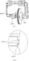
FIG. 3 is a partial structural view of the self-locking device of an endoscope according to an embodiment of the present invention; -
FIG. 4 is a detail view ofFIG. 3 of the self-locking device of an endoscope according to an embodiment of the present invention; -
FIG. 5 is a full structural view of a toggle lever of the self-locking device of an endoscope according to an embodiment of the present invention; -
FIG. 6 is a partial structural view of the toggle lever of the self-locking device of an endoscope according to an embodiment of the present invention; and -
FIG. 7 is a partial sectional view of a friction piece, shown inFIG. 6 , of the self-locking device of an endoscope according to an embodiment of the present invention. - To make the above objectives, features and advantages of the present invention clearer, the specific implementations of the present invention are described in detail below with reference to the drawings of the specification.
- Many specific details are set forth in the following description to facilitate full understanding of the present invention, but the present invention may also be implemented in other ways different from those described herein, similar derivatives may be made by those skilled in the art without departing from the connotation of the present invention, and therefore, the present invention is not limited by the specific embodiments disclosed below.
- In addition, the "one embodiment" or "embodiments" herein refers to a particular feature, structure or characteristic that may be included in at least one implementation of the present invention. The "in one embodiment" appearing in different places in the specification does not refer to the same embodiment, nor is it a separate or selective embodiment mutually exclusive with other embodiments.
- Referring to
FIGS. 1 to 5 , a first embodiment of the present invention provides a self-locking device of an endoscope. In this embodiment, the endoscope includes ahousing 100 and atoggle assembly 200. Thetoggle assembly 200 is located outside thehousing 100 and performs relative rotational motion. - The
housing 100 is provided outside the endoscope. Thehousing 100 is hollow inside to accommodate internal components and cords of the endoscope. - The
toggle assembly 200 includes atoggle support 201, anelastic support 202 and atoggle handle 203. Thetoggle handle 203 is sleeved on thetoggle support 201 and is movable along a sleeving direction. A shaft of thetoggle support 201 passes through thehousing 100 and is connected to theelastic support 202 on the other side. That is to say, thetoggle handle 203 is sleeved on thetoggle support 201, and it is movable left and right along thetoggle support 201. - An inner side of the
toggle support 201 is provided with atoggle lever 201a and afriction piece 201b. Thetoggle lever 201a has an L-shaped cross section, with a middle bend fixed to thetoggle support 201. Thetoggle lever 201a is hinged to thetoggle support 201 through afirst pin 301. When being stressed, thetoggle lever 201a is rotatable around thefirst pin 301, so as to push thefriction piece 201b to move. - It should be noted that the
toggle lever 201a and thetoggle handle 203 are hinged through asecond pin 302, a connecting end of thetoggle lever 201a is provided with a long oval hole, and thetoggle handle 203 passes through the long oval hole to be fit with thetoggle support 201. Therefore, when thetoggle handle 203 moves on thetoggle support 201, thetoggle lever 201a provided with the long oval hole is movable up and down and left and right around thesecond pin 302. The left-right direction is perpendicular to thetoggle support 201. - It should be noted that, in this embodiment, there is no connection between the
friction piece 201b and thetoggle lever 201a. - One end of the
toggle lever 201a is provided with afitting bump 201a-1, and one end of thefriction piece 201b is provided with a fittedbump 201b-1. A plane on which thefitting bump 201a-1 is located is opposite to a plane on which the fittedbump 201b-1 is located, so that the fitting bump and the fitted bump are fit with each other. - Preferably, the
fitting bump 201a-1 and the fittedbump 201b-1 respectively have smooth curved surfaces. For example, thefitting bump 201a-1 and the fittedbump 201b-1 have semicircular cross sections. - Preferably, the number of the
fitting bump 201a-1 is identical to the number of the fittedbump 201b-1. - In the present invention, a working principle of the self-locking device of the endoscope is as follows. In an initial state, the
toggle handle 203 is placed on a left side of thetoggle support 201. Thetoggle handle 203 is manually toggled to move from the left side of thetoggle support 201 to a right side of thetoggle support 201, and it stays at the right side of thetoggle support 201. When thetoggle handle 203 moves from the left side of thetoggle support 201 to the right side of thetoggle support 201, one end of the long oval hole of thetoggle lever 201a moves relative to thesecond pin 302, such that thetoggle lever 201a rotates around thefirst pin 301. As shown in the figure, in an initial position, thefitting bump 201a-1 is placed under the fittedbump 201b-1. When thetoggle lever 201a rotates around thefirst pin 301, thefitting bump 201a-1 is placed above the fittedbump 201b-1. - Referring to
FIGS. 1 to 5 , a second embodiment of the present disclosure provides a self-locking device of an endoscope. Different from the first embodiment, in the second embodiment, one end of thefriction piece 201b is fixed to the other end of theelastic support 202 through along shaft 303. - Specifically, in this embodiment, the endoscope includes a
housing 100 and atoggle assembly 200. Thetoggle assembly 200 is located outside thehousing 100 and performs relative rotational motion. - The
housing 100 is provided outside the endoscope. Thehousing 100 is hollow inside to accommodate internal components and cords of the endoscope. - The
toggle assembly 200 includes atoggle support 201, anelastic support 202 and atoggle handle 203. The toggle handle 203 is sleeved on thetoggle support 201 and is movable along a sleeving direction. A shaft of thetoggle support 201 passes through thehousing 100 and is connected to theelastic support 202 on the other side. That is to say, the toggle handle 203 is sleeved on thetoggle support 201, and it is movable left and right along thetoggle support 201. - An inner side of the
toggle support 201 is provided with atoggle lever 201a and afriction piece 201b. Thetoggle lever 201a has an L-shaped cross section, with a middle bend fixed to thetoggle support 201. Thetoggle lever 201a is hinged to thetoggle support 201 through afirst pin 301. When being stressed, thetoggle lever 201a is rotatable around thefirst pin 301, so as to push thefriction piece 201b to move. - It should be noted that the
toggle lever 201a and the toggle handle 203 are hinged through asecond pin 302, a connecting end of thetoggle lever 201a is provided with a long oval hole, and the toggle handle 203 passes through the long oval hole to be fit with thetoggle support 201. Therefore, when the toggle handle 203 moves on thetoggle support 201, thetoggle lever 201a provided with the long oval hole is movable up and down and left and right around thesecond pin 302. The left-right direction is perpendicular to thetoggle support 201. - It should be noted that, in this embodiment, there is no connection between the
friction piece 201b and thetoggle lever 201a. - Preferably, one end of the
toggle lever 201a is provided with afitting bump 201a-1, and one end of thefriction piece 201b is provided with a fittedbump 201b-1. A plane on which thefitting bump 201a-1 is located is opposite to a plane on which the fittedbump 201b-1 is located, so that the fitting bump and the fitted bump are fit with each other. - Preferably, the
fitting bump 201a-1 and the fittedbump 201b-1 respectively have smooth curved surfaces. For example, thefitting bump 201a-1 and the fittedbump 201b-1 have semicircular cross sections. - Preferably, the number of the
fitting bump 201a-1 is identical to the number of the fittedbump 201b-1. - In the present invention, a working principle of the self-locking device of the endoscope is as follows. In an initial state, the toggle handle 203 is placed on a left side of the
toggle support 201. The toggle handle 203 is manually toggled to move from the left side of thetoggle support 201 to a right side of thetoggle support 201, and it stays at the right side of thetoggle support 201. When the toggle handle 203 moves from the left side of thetoggle support 201 to the right side of thetoggle support 201, one end of the long oval hole of thetoggle lever 201a moves relative to thesecond pin 302, such that thetoggle lever 201a rotates around thefirst pin 301. As shown in the figure, in an initial position, thefitting bump 201a-1 is placed under the fittedbump 201b-1. When thetoggle lever 201a rotates around thefirst pin 301, thefitting bump 201a-1 is placed above the fittedbump 201b-1. - It should be noted that, one end of the
friction piece 201b is fixed to the other end of theelastic support 202 through thelong shaft 303. During a whole movement process, in the initial state, theelastic support 202 is in contact with thehousing 100, so the resistance of pulling a tail end of a cord through thetoggle assembly 200 is very large. The tail end of the cord is self-locking without external force, and it is difficult to be pulled by thetoggle assembly 200. When thefitting bump 201a-1 moves from below the fittedbump 201b- 1 to above the fittedbump 201b-1, thefriction piece 201b pushes thelong shaft 303 such that theelastic support 202 does not contact thehousing 100. In this way, the resistance of pulling the tail end of the cord through thetoggle assembly 200 is reduced, such that the tail end of the cord can move freely through thetoggle assembly 200. - Referring to
FIGS. 1 to 7 , another embodiment, not falling within the scope of the claims, provides a self-locking device of an endoscope. In this embodiment, thefriction piece 201b includes afirst gear 201b-2, asecond gear 201b-3, arubber sheet 201b-4, anut 201b-5 and abolt 201b-6. In thetoggle support 201, thebolt 201b-6 passes through thesecond gear 201b-3 and therubber sheet 201b-4, and is fixed to thenut 201b-5 at the other end. - It should be noted that, in this embodiment, a spring is provided between the
first gear 201b-2 and thesecond gear 201b-3, such that thefirst gear 201b-2 and thesecond gear 201b-3 can be reset without external force. - It should be noted that the fitted
bump 201b-1 is provided on thefirst gear 201b-2. - In this embodiment, a working principle of the self-locking device of the endoscope is as follows. In an initial state, the toggle handle 203 is placed on a left side of the
toggle support 201. The toggle handle 203 is manually toggled to move from the left side of thetoggle support 201 to a right side of thetoggle support 201, and it stays at the right side of thetoggle support 201. When the toggle handle 203 moves from the left side of thetoggle support 201 to the right side of thetoggle support 201, one end of the long oval hole of thetoggle lever 201a moves relative to thesecond pin 302, such that thetoggle lever 201a rotates around thefirst pin 301. As shown in the figure, in an initial position, thefitting bump 201a-1 is placed under the fittedbump 201b-1. When thetoggle lever 201a rotates around thefirst pin 301, thefitting bump 201a-1 is placed above the fittedbump 201b-1. At this time, thefirst gear 201b-2 meshes with thesecond gear 201b-3, and the tightness is adjusted by adjusting a gap between thenut 201b-5 and thehousing 100. - During the entire movement process, in the initial state, the
first gear 201b-2 meshes with thesecond gear 201b-3, and the adjustingnut 201b-5 is in close contact with thehousing 100. Thus, the resistance of pulling a tail end of a cord through thetoggle assembly 200 is very large. The tail end of the cord is self-locking without external force, and it is difficult to be pulled by thetoggle assembly 200. When the adjustingnut 201b-5 is in loose contact with thehousing 100, the resistance of thetoggle assembly 200 to pull the tail end of the cord is reduced, and thetoggle assembly 200 can easily pull the tail end of the cord. - It is important to note that the configurations and arrangements of the present invention shown in the various exemplary implementation schemes are merely illustrative. Although only a few implementation schemes are described in detail in the present invention, it should be readily understood by those referring to the disclosure that many modifications (such as the sizes, dimensions, structures, shapes, ratios, parameter values, mounting arrangements, material use, colors and orientation changes of various elements) are possibly made without departing from the novel teachings and advantages of the subject matter described in the present invention. For example, an element shown as integrally formed may be composed of multiple parts or elements, the position of the element may be reversed or otherwise altered, and the nature or number or location of the discrete elements may be altered. Accordingly, all such modifications are intended to be included within the scope of the present invention. The order or sequence of any process or method steps may be changed or re-sequenced according to alternative implementation schemes. Other substitutions, modifications, changes and omissions may be made in the design, operation and arrangement of the exemplary implementation schemes without departing from the scope of the present invention. Therefore, the present invention is not limited to a specific implementation scheme, but extends to various modifications that come within the scope of the appended claims.
- In addition, for a concise description of the exemplary implementation schemes, all features of actual implementation schemes (i.e., those that are not related to the currently considered best mode for carrying out the present invention, or those that are not related to the practice of the present invention) may not be described.
- It should be understood that a large number of specific implementation decisions may be made in the development of any actual implementation, such as in any engineering or design project. Such development efforts may be complex and time-consuming, but for those of ordinary skill who benefit from this disclosure, they do not need too many experiments, and such development efforts will be a routine work of design, manufacturing and production.
- It should be noted that the above embodiments are only intended to explain, rather than to limit the technical solutions of the present invention. Although the present invention is described in detail with reference to the preferred embodiments, those skilled in the art should understand that modifications or equivalent substitutions may be made to the technical solutions of the present invention without departing from the spirit and scope of the technical solutions of the present invention, and such modifications or equivalent substitutions should be included within the scope of the claims of the present invention.
Claims (5)
- A self-locking device of an endoscope, the endoscope comprisesa housing (100), being provided outside the endoscope and hollow inside; anda toggle assembly (200), comprising a toggle support (201), an elastic support (202) and a toggle handle (203), whereinthe toggle handle (203) is sleeved on the toggle support (201), and the toggle handle (203) is movable along a sleeving direction; anda shaft of the toggle support (201) passes through the housing (100), and the shaft of the toggle support (201) is connected to a first end of the elastic support (202) on an other side;characterized in thatan inner side of the toggle support (201) is provided with a toggle lever (201a) and a friction piece (201b); and a first end of the toggle lever (201a) is hinged to the toggle handle (203);the toggle lever (201a) has an L-shaped cross section, with a middle bend fixed to the toggle support (201); the toggle lever (201a) is hinged to the toggle support (201) through a first pin (301); and when being stressed, the toggle lever (201a) is rotatable around the first pin (301), so as to push the friction piece (201b) to move; anda second end of the toggle lever (201a) is provided with a fitting bump (201a-1), and a first end of the friction piece (201b) is provided with a fitted bump (201b-1); and a first plane is opposite to a second plane, wherein the fitting bump (201a-1) is located on the first plane and the fitted bump (201b-1) is located on the second plane, wherein the fitting bump and the fitted bump are fit with each other.
- The self-locking device of the endoscope according to claim 1, characterized in that the fitting bump (201a-1) and the fitted bump (201b-1) each have smooth curved surfaces.
- The self-locking device of the endoscope according to claim 2, characterized in that the toggle lever (201a) and the toggle handle (203) are hinged through a second pin (302); the first end of the toggle lever (201a) is provided with a long oval hole, wherein the first end of the toggle lever (201a) is a connecting end; and the second pin (302) passes through the long oval hole to be fit with the toggle support (201).
- The self-locking device of the endoscope according to any one of claims 1 to 3, characterized in that a second end of the friction piece (201b) is fixed to a second end of the elastic support (202) through a long shaft (303).
- The self-locking device of the endoscope according to claim 4, characterized in that a number of the fitting bump (201a-1) is identical to a number of the fitted bump (201b-1).
Applications Claiming Priority (2)
| Application Number | Priority Date | Filing Date | Title |
|---|---|---|---|
| CN201910726342.4A CN110432853B (en) | 2019-08-07 | 2019-08-07 | Self-locking device of endoscope |
| PCT/CN2020/089658 WO2021022859A1 (en) | 2019-08-07 | 2020-05-11 | Self-locking device for endoscope |
Publications (3)
| Publication Number | Publication Date |
|---|---|
| EP3998010A1 EP3998010A1 (en) | 2022-05-18 |
| EP3998010A4 EP3998010A4 (en) | 2022-09-14 |
| EP3998010B1 true EP3998010B1 (en) | 2023-03-15 |
Family
ID=68433732
Family Applications (1)
| Application Number | Title | Priority Date | Filing Date |
|---|---|---|---|
| EP20848945.0A Active EP3998010B1 (en) | 2019-08-07 | 2020-05-11 | Self-locking device for endoscope |
Country Status (6)
| Country | Link |
|---|---|
| US (1) | US11969146B2 (en) |
| EP (1) | EP3998010B1 (en) |
| JP (1) | JP7127925B2 (en) |
| CN (1) | CN110432853B (en) |
| ES (1) | ES2942304T3 (en) |
| WO (1) | WO2021022859A1 (en) |
Families Citing this family (2)
| Publication number | Priority date | Publication date | Assignee | Title |
|---|---|---|---|---|
| CN110432853B (en) | 2019-08-07 | 2024-03-19 | 湖南省华芯医疗器械有限公司 | Self-locking device of endoscope |
| CN111202488A (en) * | 2020-03-12 | 2020-05-29 | 湖南省华芯医疗器械有限公司 | Self-locking device suitable for endoscope |
Family Cites Families (14)
| Publication number | Priority date | Publication date | Assignee | Title |
|---|---|---|---|---|
| DE3729131C1 (en) | 1987-09-01 | 1989-03-30 | Wolf Gmbh Richard | Control device for deflecting the distal end of an endoscope |
| DE19650721C2 (en) * | 1996-12-06 | 1999-08-12 | Wolf Gmbh Richard | Control device for guiding the distal end of an endoscope |
| JP2004267419A (en) * | 2003-03-07 | 2004-09-30 | Pentax Corp | Electronic endoscope |
| US8366604B2 (en) | 2009-06-03 | 2013-02-05 | Gyrus Acmi Inc. | Endoscope combined deflection control and lock |
| CN103140158B (en) * | 2011-04-28 | 2014-07-02 | 奥林巴斯医疗株式会社 | Endoscope |
| CN103654693B (en) * | 2013-12-25 | 2016-08-17 | 武汉佑康科技有限公司 | Modified model angle-adjusting mechanism for endoscope |
| CN104523321B (en) * | 2014-12-30 | 2017-06-13 | 杭州光典医疗器械有限公司 | The card locking device and operating theater instruments of carrier state handoff functionality |
| JP6399374B2 (en) * | 2015-06-02 | 2018-10-03 | 武漢佑康科技有限公司 | Multi-directional swivel endoscope |
| JP6447894B2 (en) * | 2015-06-02 | 2019-01-09 | 武漢佑康科技有限公司 | Self-locking angle adjustment mechanism for endoscope |
| US11559322B2 (en) * | 2017-08-03 | 2023-01-24 | Biosense Webster (Israel) Ltd. | Multi-functional ENT tool |
| CN109077696B (en) * | 2018-08-03 | 2020-11-13 | 苏州中科先进技术研究院有限公司 | Endoscope and endoscope snake bone adjusting device thereof |
| CN210990136U (en) * | 2019-08-07 | 2020-07-14 | 湖南省华芯医疗器械有限公司 | Self-locking device of endoscope |
| CN110367907B (en) * | 2019-08-07 | 2024-04-12 | 湖南省华芯医疗器械有限公司 | Hand-held end of endoscope |
| CN110432853B (en) * | 2019-08-07 | 2024-03-19 | 湖南省华芯医疗器械有限公司 | Self-locking device of endoscope |
-
2019
- 2019-08-07 CN CN201910726342.4A patent/CN110432853B/en active Active
-
2020
- 2020-05-11 US US17/633,497 patent/US11969146B2/en active Active
- 2020-05-11 JP JP2022502472A patent/JP7127925B2/en active Active
- 2020-05-11 EP EP20848945.0A patent/EP3998010B1/en active Active
- 2020-05-11 WO PCT/CN2020/089658 patent/WO2021022859A1/en unknown
- 2020-05-11 ES ES20848945T patent/ES2942304T3/en active Active
Also Published As
| Publication number | Publication date |
|---|---|
| JP7127925B2 (en) | 2022-08-30 |
| CN110432853B (en) | 2024-03-19 |
| US20220287547A1 (en) | 2022-09-15 |
| WO2021022859A1 (en) | 2021-02-11 |
| EP3998010A4 (en) | 2022-09-14 |
| EP3998010A1 (en) | 2022-05-18 |
| ES2942304T3 (en) | 2023-05-31 |
| US11969146B2 (en) | 2024-04-30 |
| CN110432853A (en) | 2019-11-12 |
| JP2022536193A (en) | 2022-08-12 |
Similar Documents
| Publication | Publication Date | Title |
|---|---|---|
| EP3998010B1 (en) | Self-locking device for endoscope | |
| CN109176586B (en) | Self-adaptive flexible paw based on torsion spring and robot | |
| CN103659825B (en) | Bending self-locking pneumatic under-actuated robot finger device | |
| CN107097218B (en) | Wire traction variable-rigidity mechanism based on mechanical locking | |
| US7765897B2 (en) | Ratchet wrench | |
| US20140260755A1 (en) | Multi-jointed arm assembly | |
| EP4018912B1 (en) | Self-locking device suitable for endoscope | |
| CN108555959B (en) | Two-degree-of-freedom linkage joint section and flexible mechanical arm | |
| JP2016131773A (en) | Multijoint-structured forceps | |
| CN104723357B (en) | Robots arm and robot including the robots arm | |
| KR102154391B1 (en) | Apparatus gripper | |
| US20210186637A1 (en) | Bending structure and flexible tube for medical manipulator | |
| EP3998011A1 (en) | Handheld end of endoscope | |
| CN107542920B (en) | Cable joint assembly and vehicle with same | |
| CN108115715B (en) | Differential connecting rod reverse transmission synergistic parallel clamping self-adaptive robot finger device | |
| CN107542748B (en) | Stay cable joint assembly | |
| CN112518781B (en) | Manipulator and mechanical finger thereof | |
| WO2021162089A1 (en) | Bending structure and joint function part | |
| CN210990136U (en) | Self-locking device of endoscope | |
| JP2016061335A (en) | Butterfly valve assembly method and assembly device | |
| WO2016180365A1 (en) | Continuum differential mechanism and mechanical arm | |
| JP2013035109A (en) | Remote control device | |
| CN211250089U (en) | Mechanical arm, tail end driving structure thereof and robot | |
| WO2023095861A1 (en) | Flexural structure and half-finished product thereof | |
| CN219661757U (en) | Adjusting component and control handle |
Legal Events
| Date | Code | Title | Description |
|---|---|---|---|
| STAA | Information on the status of an ep patent application or granted ep patent |
Free format text: STATUS: THE INTERNATIONAL PUBLICATION HAS BEEN MADE |
|
| PUAI | Public reference made under article 153(3) epc to a published international application that has entered the european phase |
Free format text: ORIGINAL CODE: 0009012 |
|
| STAA | Information on the status of an ep patent application or granted ep patent |
Free format text: STATUS: REQUEST FOR EXAMINATION WAS MADE |
|
| 17P | Request for examination filed |
Effective date: 20220210 |
|
| AK | Designated contracting states |
Kind code of ref document: A1 Designated state(s): AL AT BE BG CH CY CZ DE DK EE ES FI FR GB GR HR HU IE IS IT LI LT LU LV MC MK MT NL NO PL PT RO RS SE SI SK SM TR |
|
| A4 | Supplementary search report drawn up and despatched |
Effective date: 20220812 |
|
| RIC1 | Information provided on ipc code assigned before grant |
Ipc: A61B 1/005 20060101ALI20220808BHEP Ipc: A61B 1/00 20060101AFI20220808BHEP |
|
| DAV | Request for validation of the european patent (deleted) | ||
| DAX | Request for extension of the european patent (deleted) | ||
| GRAP | Despatch of communication of intention to grant a patent |
Free format text: ORIGINAL CODE: EPIDOSNIGR1 |
|
| STAA | Information on the status of an ep patent application or granted ep patent |
Free format text: STATUS: GRANT OF PATENT IS INTENDED |
|
| INTG | Intention to grant announced |
Effective date: 20221130 |
|
| GRAS | Grant fee paid |
Free format text: ORIGINAL CODE: EPIDOSNIGR3 |
|
| GRAA | (expected) grant |
Free format text: ORIGINAL CODE: 0009210 |
|
| STAA | Information on the status of an ep patent application or granted ep patent |
Free format text: STATUS: THE PATENT HAS BEEN GRANTED |
|
| AK | Designated contracting states |
Kind code of ref document: B1 Designated state(s): AL AT BE BG CH CY CZ DE DK EE ES FI FR GB GR HR HU IE IS IT LI LT LU LV MC MK MT NL NO PL PT RO RS SE SI SK SM TR |
|
| REG | Reference to a national code |
Ref country code: CH Ref legal event code: EP Ref country code: GB Ref legal event code: FG4D |
|
| REG | Reference to a national code |
Ref country code: DE Ref legal event code: R096 Ref document number: 602020008928 Country of ref document: DE |
|
| REG | Reference to a national code |
Ref country code: IE Ref legal event code: FG4D |
|
| REG | Reference to a national code |
Ref country code: AT Ref legal event code: REF Ref document number: 1553507 Country of ref document: AT Kind code of ref document: T Effective date: 20230415 |
|
| REG | Reference to a national code |
Ref country code: ES Ref legal event code: FG2A Ref document number: 2942304 Country of ref document: ES Kind code of ref document: T3 Effective date: 20230531 |
|
| REG | Reference to a national code |
Ref country code: LT Ref legal event code: MG9D |
|
| REG | Reference to a national code |
Ref country code: NL Ref legal event code: MP Effective date: 20230315 |
|
| PG25 | Lapsed in a contracting state [announced via postgrant information from national office to epo] |
Ref country code: RS Free format text: LAPSE BECAUSE OF FAILURE TO SUBMIT A TRANSLATION OF THE DESCRIPTION OR TO PAY THE FEE WITHIN THE PRESCRIBED TIME-LIMIT Effective date: 20230315 Ref country code: NO Free format text: LAPSE BECAUSE OF FAILURE TO SUBMIT A TRANSLATION OF THE DESCRIPTION OR TO PAY THE FEE WITHIN THE PRESCRIBED TIME-LIMIT Effective date: 20230615 Ref country code: LV Free format text: LAPSE BECAUSE OF FAILURE TO SUBMIT A TRANSLATION OF THE DESCRIPTION OR TO PAY THE FEE WITHIN THE PRESCRIBED TIME-LIMIT Effective date: 20230315 Ref country code: LT Free format text: LAPSE BECAUSE OF FAILURE TO SUBMIT A TRANSLATION OF THE DESCRIPTION OR TO PAY THE FEE WITHIN THE PRESCRIBED TIME-LIMIT Effective date: 20230315 Ref country code: HR Free format text: LAPSE BECAUSE OF FAILURE TO SUBMIT A TRANSLATION OF THE DESCRIPTION OR TO PAY THE FEE WITHIN THE PRESCRIBED TIME-LIMIT Effective date: 20230315 |
|
| PGFP | Annual fee paid to national office [announced via postgrant information from national office to epo] |
Ref country code: IT Payment date: 20230531 Year of fee payment: 4 Ref country code: FR Payment date: 20230530 Year of fee payment: 4 Ref country code: ES Payment date: 20230615 Year of fee payment: 4 Ref country code: DE Payment date: 20230526 Year of fee payment: 4 |
|
| REG | Reference to a national code |
Ref country code: AT Ref legal event code: MK05 Ref document number: 1553507 Country of ref document: AT Kind code of ref document: T Effective date: 20230315 |
|
| PG25 | Lapsed in a contracting state [announced via postgrant information from national office to epo] |
Ref country code: SE Free format text: LAPSE BECAUSE OF FAILURE TO SUBMIT A TRANSLATION OF THE DESCRIPTION OR TO PAY THE FEE WITHIN THE PRESCRIBED TIME-LIMIT Effective date: 20230315 Ref country code: NL Free format text: LAPSE BECAUSE OF FAILURE TO SUBMIT A TRANSLATION OF THE DESCRIPTION OR TO PAY THE FEE WITHIN THE PRESCRIBED TIME-LIMIT Effective date: 20230315 Ref country code: GR Free format text: LAPSE BECAUSE OF FAILURE TO SUBMIT A TRANSLATION OF THE DESCRIPTION OR TO PAY THE FEE WITHIN THE PRESCRIBED TIME-LIMIT Effective date: 20230616 Ref country code: FI Free format text: LAPSE BECAUSE OF FAILURE TO SUBMIT A TRANSLATION OF THE DESCRIPTION OR TO PAY THE FEE WITHIN THE PRESCRIBED TIME-LIMIT Effective date: 20230315 |
|
| PG25 | Lapsed in a contracting state [announced via postgrant information from national office to epo] |
Ref country code: SM Free format text: LAPSE BECAUSE OF FAILURE TO SUBMIT A TRANSLATION OF THE DESCRIPTION OR TO PAY THE FEE WITHIN THE PRESCRIBED TIME-LIMIT Effective date: 20230315 Ref country code: RO Free format text: LAPSE BECAUSE OF FAILURE TO SUBMIT A TRANSLATION OF THE DESCRIPTION OR TO PAY THE FEE WITHIN THE PRESCRIBED TIME-LIMIT Effective date: 20230315 Ref country code: PT Free format text: LAPSE BECAUSE OF FAILURE TO SUBMIT A TRANSLATION OF THE DESCRIPTION OR TO PAY THE FEE WITHIN THE PRESCRIBED TIME-LIMIT Effective date: 20230717 Ref country code: EE Free format text: LAPSE BECAUSE OF FAILURE TO SUBMIT A TRANSLATION OF THE DESCRIPTION OR TO PAY THE FEE WITHIN THE PRESCRIBED TIME-LIMIT Effective date: 20230315 Ref country code: CZ Free format text: LAPSE BECAUSE OF FAILURE TO SUBMIT A TRANSLATION OF THE DESCRIPTION OR TO PAY THE FEE WITHIN THE PRESCRIBED TIME-LIMIT Effective date: 20230315 Ref country code: AT Free format text: LAPSE BECAUSE OF FAILURE TO SUBMIT A TRANSLATION OF THE DESCRIPTION OR TO PAY THE FEE WITHIN THE PRESCRIBED TIME-LIMIT Effective date: 20230315 |
|
| PG25 | Lapsed in a contracting state [announced via postgrant information from national office to epo] |
Ref country code: SK Free format text: LAPSE BECAUSE OF FAILURE TO SUBMIT A TRANSLATION OF THE DESCRIPTION OR TO PAY THE FEE WITHIN THE PRESCRIBED TIME-LIMIT Effective date: 20230315 Ref country code: PL Free format text: LAPSE BECAUSE OF FAILURE TO SUBMIT A TRANSLATION OF THE DESCRIPTION OR TO PAY THE FEE WITHIN THE PRESCRIBED TIME-LIMIT Effective date: 20230315 Ref country code: IS Free format text: LAPSE BECAUSE OF FAILURE TO SUBMIT A TRANSLATION OF THE DESCRIPTION OR TO PAY THE FEE WITHIN THE PRESCRIBED TIME-LIMIT Effective date: 20230715 |
|
| REG | Reference to a national code |
Ref country code: DE Ref legal event code: R097 Ref document number: 602020008928 Country of ref document: DE |
|
| REG | Reference to a national code |
Ref country code: CH Ref legal event code: PL |
|
| PG25 | Lapsed in a contracting state [announced via postgrant information from national office to epo] |
Ref country code: MC Free format text: LAPSE BECAUSE OF FAILURE TO SUBMIT A TRANSLATION OF THE DESCRIPTION OR TO PAY THE FEE WITHIN THE PRESCRIBED TIME-LIMIT Effective date: 20230315 |
|
| PLBE | No opposition filed within time limit |
Free format text: ORIGINAL CODE: 0009261 |
|
| STAA | Information on the status of an ep patent application or granted ep patent |
Free format text: STATUS: NO OPPOSITION FILED WITHIN TIME LIMIT |
|
| REG | Reference to a national code |
Ref country code: BE Ref legal event code: MM Effective date: 20230531 |
|
| PG25 | Lapsed in a contracting state [announced via postgrant information from national office to epo] |
Ref country code: SI Free format text: LAPSE BECAUSE OF FAILURE TO SUBMIT A TRANSLATION OF THE DESCRIPTION OR TO PAY THE FEE WITHIN THE PRESCRIBED TIME-LIMIT Effective date: 20230315 Ref country code: MC Free format text: LAPSE BECAUSE OF FAILURE TO SUBMIT A TRANSLATION OF THE DESCRIPTION OR TO PAY THE FEE WITHIN THE PRESCRIBED TIME-LIMIT Effective date: 20230315 Ref country code: LU Free format text: LAPSE BECAUSE OF NON-PAYMENT OF DUE FEES Effective date: 20230511 Ref country code: LI Free format text: LAPSE BECAUSE OF NON-PAYMENT OF DUE FEES Effective date: 20230531 Ref country code: DK Free format text: LAPSE BECAUSE OF FAILURE TO SUBMIT A TRANSLATION OF THE DESCRIPTION OR TO PAY THE FEE WITHIN THE PRESCRIBED TIME-LIMIT Effective date: 20230315 Ref country code: CH Free format text: LAPSE BECAUSE OF NON-PAYMENT OF DUE FEES Effective date: 20230531 |
|
| 26N | No opposition filed |
Effective date: 20231218 |
|
| REG | Reference to a national code |
Ref country code: IE Ref legal event code: MM4A |
|
| PG25 | Lapsed in a contracting state [announced via postgrant information from national office to epo] |
Ref country code: IE Free format text: LAPSE BECAUSE OF NON-PAYMENT OF DUE FEES Effective date: 20230511 |
|
| PG25 | Lapsed in a contracting state [announced via postgrant information from national office to epo] |
Ref country code: IE Free format text: LAPSE BECAUSE OF NON-PAYMENT OF DUE FEES Effective date: 20230511 |