EP3997618B1 - Drucken von nicht-benutzermustern mit einem druckauftrag - Google Patents
Drucken von nicht-benutzermustern mit einem druckauftrag Download PDFInfo
- Publication number
- EP3997618B1 EP3997618B1 EP20837552.7A EP20837552A EP3997618B1 EP 3997618 B1 EP3997618 B1 EP 3997618B1 EP 20837552 A EP20837552 A EP 20837552A EP 3997618 B1 EP3997618 B1 EP 3997618B1
- Authority
- EP
- European Patent Office
- Prior art keywords
- task
- sub
- section
- tasks
- printing
- Prior art date
- Legal status (The legal status is an assumption and is not a legal conclusion. Google has not performed a legal analysis and makes no representation as to the accuracy of the status listed.)
- Active
Links
Images





Classifications
-
- G—PHYSICS
- G06—COMPUTING OR CALCULATING; COUNTING
- G06K—GRAPHICAL DATA READING; PRESENTATION OF DATA; RECORD CARRIERS; HANDLING RECORD CARRIERS
- G06K15/00—Arrangements for producing a permanent visual presentation of the output data, e.g. computer output printers
- G06K15/02—Arrangements for producing a permanent visual presentation of the output data, e.g. computer output printers using printers
- G06K15/18—Conditioning data for presenting it to the physical printing elements
- G06K15/1867—Post-processing of the composed and rasterized print image
- G06K15/1882—Post-processing of the composed and rasterized print image involving operator action
- G06K15/1885—Post-processing of the composed and rasterized print image involving operator action for modifying the layout of a document
-
- G—PHYSICS
- G06—COMPUTING OR CALCULATING; COUNTING
- G06K—GRAPHICAL DATA READING; PRESENTATION OF DATA; RECORD CARRIERS; HANDLING RECORD CARRIERS
- G06K15/00—Arrangements for producing a permanent visual presentation of the output data, e.g. computer output printers
- G06K15/02—Arrangements for producing a permanent visual presentation of the output data, e.g. computer output printers using printers
- G06K15/027—Test patterns and calibration
-
- G—PHYSICS
- G06—COMPUTING OR CALCULATING; COUNTING
- G06K—GRAPHICAL DATA READING; PRESENTATION OF DATA; RECORD CARRIERS; HANDLING RECORD CARRIERS
- G06K15/00—Arrangements for producing a permanent visual presentation of the output data, e.g. computer output printers
- G06K15/02—Arrangements for producing a permanent visual presentation of the output data, e.g. computer output printers using printers
- G06K15/18—Conditioning data for presenting it to the physical printing elements
- G06K15/1835—Transforming generic data
- G06K15/1836—Rasterization
-
- H—ELECTRICITY
- H04—ELECTRIC COMMUNICATION TECHNIQUE
- H04N—PICTORIAL COMMUNICATION, e.g. TELEVISION
- H04N1/00—Scanning, transmission or reproduction of documents or the like, e.g. facsimile transmission; Details thereof
- H04N1/00002—Diagnosis, testing or measuring; Detecting, analysing or monitoring not otherwise provided for
- H04N1/00007—Diagnosis, testing or measuring; Detecting, analysing or monitoring not otherwise provided for relating to particular apparatus or devices
- H04N1/00015—Reproducing apparatus
-
- H—ELECTRICITY
- H04—ELECTRIC COMMUNICATION TECHNIQUE
- H04N—PICTORIAL COMMUNICATION, e.g. TELEVISION
- H04N1/00—Scanning, transmission or reproduction of documents or the like, e.g. facsimile transmission; Details thereof
- H04N1/00002—Diagnosis, testing or measuring; Detecting, analysing or monitoring not otherwise provided for
- H04N1/00026—Methods therefor
- H04N1/0005—Methods therefor in service, i.e. during normal operation
-
- H—ELECTRICITY
- H04—ELECTRIC COMMUNICATION TECHNIQUE
- H04N—PICTORIAL COMMUNICATION, e.g. TELEVISION
- H04N1/00—Scanning, transmission or reproduction of documents or the like, e.g. facsimile transmission; Details thereof
- H04N1/0035—User-machine interface; Control console
- H04N1/00405—Output means
- H04N1/00408—Display of information to the user, e.g. menus
- H04N1/0044—Display of information to the user, e.g. menus for image preview or review, e.g. to help the user position a sheet
-
- H—ELECTRICITY
- H04—ELECTRIC COMMUNICATION TECHNIQUE
- H04N—PICTORIAL COMMUNICATION, e.g. TELEVISION
- H04N1/00—Scanning, transmission or reproduction of documents or the like, e.g. facsimile transmission; Details thereof
- H04N1/0035—User-machine interface; Control console
- H04N1/00405—Output means
- H04N1/00408—Display of information to the user, e.g. menus
- H04N1/0044—Display of information to the user, e.g. menus for image preview or review, e.g. to help the user position a sheet
- H04N1/00442—Simultaneous viewing of a plurality of images, e.g. using a mosaic display arrangement of thumbnails
- H04N1/00456—Simultaneous viewing of a plurality of images, e.g. using a mosaic display arrangement of thumbnails for layout preview, e.g. page layout
-
- H—ELECTRICITY
- H04—ELECTRIC COMMUNICATION TECHNIQUE
- H04N—PICTORIAL COMMUNICATION, e.g. TELEVISION
- H04N1/00—Scanning, transmission or reproduction of documents or the like, e.g. facsimile transmission; Details thereof
- H04N1/00567—Handling of original or reproduction media, e.g. cutting, separating, stacking
- H04N1/00644—Counting or calculating, e.g. a number of remaining sheets
-
- H—ELECTRICITY
- H04—ELECTRIC COMMUNICATION TECHNIQUE
- H04N—PICTORIAL COMMUNICATION, e.g. TELEVISION
- H04N1/00—Scanning, transmission or reproduction of documents or the like, e.g. facsimile transmission; Details thereof
- H04N1/387—Composing, repositioning or otherwise geometrically modifying originals
-
- H—ELECTRICITY
- H04—ELECTRIC COMMUNICATION TECHNIQUE
- H04N—PICTORIAL COMMUNICATION, e.g. TELEVISION
- H04N1/00—Scanning, transmission or reproduction of documents or the like, e.g. facsimile transmission; Details thereof
- H04N1/387—Composing, repositioning or otherwise geometrically modifying originals
- H04N1/3872—Repositioning or masking
- H04N1/3873—Repositioning or masking defined only by a limited number of coordinate points or parameters, e.g. corners, centre; for trimming
- H04N1/3875—Repositioning or masking defined only by a limited number of coordinate points or parameters, e.g. corners, centre; for trimming combined with enlarging or reducing
Definitions
- the present application is related to printing, and more specifically to methods and systems that print non-user patterns along with a print job.
- non-user The systems and methods presented here completely separate non-user patterns from the user jobs being printed. Cycling through a set of patterns in an order determined by the manufacturer or printer operator (i.e., "non-user") allows for any number of printer-specific tasks to be setup independent of the user jobs being printed. In fact, depending on the number of images in the job and the number of patterns provided by the manufacturer or printer operator, the patterns may appear on different images of the job each time the job is printed. This is because the patterns are generated and processed according to the needs of the manufacturer or printer operator, independent of the user jobs being printed.
- the present invention is defined by the subject-matter of the appended claims. Further features of the present invention will become apparent from the following description of exemplary embodiments with reference to the attached drawings.
- the systems and methods presented here completely separate non-user patterns from the user jobs being printed. Cycling through a set of patterns in an order determined by the manufacturer or printer operator allows for any number of printer-specific tasks to be setup independent of the user jobs being printed. In fact, depending on the number of images in the job and the number of patterns provided by the manufacturer, the patterns may appear on different images of the job each time the job is printed. This is because the patterns are generated and processed according to the needs of the manufacturer or printer operator, independent of the user jobs being printed.
- the system and methods presented here can enable management and/or control of the placement of raster data (unrelated to a print job) around the borders of any print job.
- This raster data could be nearly anything from a printer manufacturer's set of pre-defined, static print patterns used for nozzle-out and/or uniformity inspection, to a printer operator's dynamically generated patterns (such as print time, job name, or periodic length indicators) to be placed around the borders of any print job.
- the Raster Overlay, Underlay, and/or Stitcher (ROUS) process is a universal, highly configurable software that supports overlaying (adding raster data on top of a user's page/image data, thereby replacing any overlapping raster), underlaying (adding beneath page/image raster data, replacing any overlapping blank/empty raster), and/or stitching (adding around existing page boundary, thereby increasing the overall output dimensions).
- the ROUS process can apply different raster data, i.e. patterns, to each image transferred to the printer/press-even for multiple copies of the same page/image in a user's job because this process is designed to be applied just prior to data transfer to the printer/press.
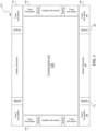
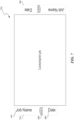
- FIG. 1 shows a printing image layout that can contain a first task and a second task to print.
- the image can be printed on a substrate including plastic films or foils, release liner, textiles, plastic containers, any variety of paper (lightweight, heavyweight, coated, uncoated, paperboard, cardboard, etc.), and/or parchment.
- the first task can be content to print such as a print job
- the second task can be the raster data such as a pattern designed to test the functioning of a printer.
- the second task can be a non-user pattern, defined by various entities such as a printing operator, a printer manufacturer, and/or a processor implementing a ROUS process.
- the ROUS process is defined by a layout 100 of the printing image.
- the ROUS process can define as many layouts 100 as needed, cycling through layouts 100 in a programmatic manner.
- the first task can be printed in the center region 105 while the second task can be printed in the peripheral regions defined by sections 110, 120, 130, 140.
- Each layout 100 can support up to four sections-two horizontal sections 110, 120 (one for the top of the page/image and one for the bottom) and two vertical sections 130, 140 (one for the left of the page/image and one for the right).
- Each section 110, 120, 130, 140 can include two fixed sub-sections 150, 160 (only two labeled for brevity) at either end of the section 110, 120, 130, 140 and one variable sub-section 190 (only one labeled for brevity) between the two fixed sub-sections 150, 160.
- the sections 110, 120, 130, 140 are individually configurable, allowing a ROUS process/use to define: 1) if the section is enabled, 2) size of the section, 3) placement of the section, 4) spacing 170, 180 (only 2 labeled for brevity) between sub-sections, and 5) the mode (i.e., overlay, underlay, or stitch).
- the ROUS process does not print anything within that section, and the section 110, 120, 130, 140 can be used as a margin between two print job images.
- the size of the section 110, 120, 130, 140 can be adjusted to be larger or smaller.
- the section 110, 120, 130, 140 can be placed at the edge of the paper as shown in FIG. 1 , or there can be a margin between the section and the edge of the paper.
- the mode can specify how to combine the second task with any images associated with the print job that need to be printed in the sections 110, 120, 130, 140.
- the ROUS process can add the second task on top of the print job to be printed in the sections 110, 120, 130, 140, thereby replacing any part of the print job that overlaps with the second task.
- the mode is underlay, the ROUS process can add the second task beneath the print job to be printed in the sections 110, 120, 130, 140, thereby having the second task replace any blank space that overlaps with the second task.
- the mode is stitch, the ROUS process can add the second task around the existing page boundary, in the sections 110, 120, 130, 140, thereby increasing the overall output dimensions.
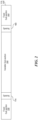
- FIG. 2 shows a horizontal section 110, 120 in FIG. 1 .
- the ROUS process can individually configure each sub-section 150, 160, 190.
- the ROUS can define: 1) if the sub-section is enabled, 2) size of the sub-section, 3) alignment of the sub-section, and 4) the task to be associated with the sub-section.
- the ROUS process does not print anything within that sub-section 150, 160, 190.
- the size of each sub-section 150, 160, 190 in the layouts 100 in FIG. 1 can be adjusted independently of all the other sub-sections in the layout 100.
- the ROUS process can also define: 1) if the pre-defined task should be repeated within the sub-section, and if so, 2) the spacing between the repeated task.
- the predefined task can include a nozzle-out pattern for black color as shown in FIG. 3A , and the nozzle-out pattern can be repeated within the variable sub-section 190 in black, or in a different color. Further, the ROUS process can adjust the spacing between the nozzle-out patterns.
- the ROUS process can individually configure each task within the sub-section 150, 160, 190 and can define: 1) size of the task, 2) offset (both horizontal and vertical) of the task, and 3) byte alignment of the task. If the task dimensions are larger than the sub-section 150, 160, 190 in which the task is to be printed, the task can be automatically cropped. To define the size of the task, the ROUS process can manipulate the task by scaling, rotating, cropping, etc. To define the offset of the task, the ROUS process can translate the task. To define the byte alignment of the task, the ROUS process can determine whether to print the task at 1 byte, 2 bytes, 3 bytes, etc. boundary.
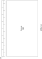
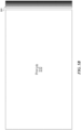
- FIGS. 3A-3B show examples of manufacturer patterns that can be printed within the various sections 110, 120, 130, 140 in FIG. 1 .
- One application of the ROUS process is the real-time printing of inline measurement test patterns for on-the-fly, nozzle-out and/or uniformity inspection.
- the test patterns 300, 310 usually consist of a handful of patterns for each ink that is supported by the printer/press.
- FIG. 3A shows a nozzle-out pattern 300 to test the nozzles printing black.
- FIG. 3B shows a uniformity pattern 310 to test uniformity of an ink used by the printer, which in FIG. 3B is black.
- FIGS. 4A-4B show various errors that can be produced by printing patterns 300, 310 in FIGS. 3A-3B .
- Printed pattern 400 in FIG. 4A shows errors 405 (only one labeled for brevity) in printing.
- the error 405 can indicate that the nozzle is clogged, the printer head is misaligned, the printer head needs to be cleaned, etc.
- Printed pattern 410 in FIG. 4B shows errors such as vertical streaks 420.
- the error 420 can indicate that the printer is low on ink.
- a notification can be sent to a user to correct the errors, or in some cases, the errors can be corrected automatically. For example, when the printer head is misaligned, the printer head can be automatically moved, and the test pattern can be reprinted until the printed pattern 400 matches the pattern 300 in FIG. 3A .
- FIGS. 5A-5B show patterns 300 in FIG. 3A , 310 in FIG. 3B printed along with a print job.
- the nozzle-out pattern 300 is printed in the upper horizontal section 110 in FIG. 1 along with the print job 500 to produce printed nozzle-out pattern 530.
- the width of the fixed sub-sections and the variable sub-section has been adjusted as compared to FIG. 1 .
- the fixed sub-sections of section 110 can be disabled, while the variable sub-section can have its width adjusted to match the width of the print job 500.
- the variable sub-section can contain the nozzle-out image in a different color, such as red.
- the uniformity pattern 310 in black color is printed in the right vertical section 140 in FIG. 1 along with the print job 510. Because the uniformity pattern 310 does not fit within the right vertical section 140, the uniformity pattern 310 has been cropped to obtain uniformity pattern 520. Uniformity pattern 520 can be printed within a fixed sub-section, or can be printed within the variable sub-section. When uniformity pattern 520 is printed within the fixed sub-section, the variable sub-section and the second fixed sub-section can be disabled, and the length of the enabled fixed sub-section can be adjusted.
- the patterns 300, 310 can be pre-defined by the printer/press manufacturer to work with whatever measurement system such as the Dedot point system, the American point system, the metric system, etc.
- a printer can have four colors, cyan, magenta, yellow, and black (CMYK).
- the manufacturer can create 10 nozzle-out patterns and one uniformity pattern for each color, for a total of 44 patterns.
- the ROUS process can receive an input from the manufacturer to print one pattern at the top of each printed page. Alternatively, the ROUS process can determine that the print job contains more than 44 pages and can determine to print one pattern of the top of each page. If the print job contains less than 44 pages, the ROUS process can print multiple patterns within the sections 110, 120, 130, 140 in FIG. 1 of the page, to accommodate all 44 patents within the print job.
- the ROUS process can distribute 44 patterns within the various sub-sections 150, 160 in FIG. 1 to print all of the 44 patterns within 10 pages.
- the ROUS process can print 12 patterns in each sub-section 150, 160 on the one page, and the remainder of the patterns can be printed in the margins of subsequent print jobs.
- the manufacturer may want to print the nozzle-out patterns for all colors first (in order from cyan, magenta, yellow, to black), followed by the uniformity patterns for all colors (in order from cyan, magenta, yellow, to black).
- the manufacturer may want to print these patterns every 10,000 images/pages.
- All of this information can be used to configure the ROUS process resulting in the ROUS process printing 10,000 images/pages without any test patterns, followed by 44 images/pages (that would sequentially add the 10 cyan nozzle-out patterns, the 10 magenta nozzle-out patterns, the 10 yellow nozzle-out patterns, the 10 black nozzle-out patterns, the 1 cyan uniformity pattern, the 1 magenta uniformity pattern, the 1 yellow uniformity pattern, and the 1 black uniformity pattern individually to the top of the image/page), followed by 10,000 images/pages without any test patterns, and so on.
- the ROUS process can be configured using an input file specifying the desired printing sequence.
- a user can be printing a thousand meters of a textile, and at every meter a label needs to be printed on the side of the textile, such as every 1 m, 2 m, 3 m, 4 m, etc.
- the ROUS process can disable the horizontal sections 110, 120 in FIG. 1 and a side section 140 in FIG. 1 .
- the ROUS process can print the task within the side section 130 in FIG. 1 .
- the task to print can be a 10-centimeter- or a 20-centimeter-long image.
- the ROUS process can print the task every 1 m, 2 m, 3 m, 4 m, etc.
- the ROUS process can be dynamic in the sense that if the printing task is stopped, the ROUS process can remember the next pattern that needs to be printed, so after the task is restarted, the next pattern is printed at 1 m spacing from the previous pattern.
- the printer may need to be stopped.
- the ROUS process can print the correct pattern in the correct location.
- FIG. 6 shows a dynamic job information to be printed along edges of a printing image.
- the ROUS process can print job information 600 such as the job name 610, the date 620, and the current distance marker 630 in the sections 110, 120, 130, 140 in FIG. 1 .
- the job name and the date can be same throughout printing, while the current distance marker 630 can change as the distance from the beginning of the print job increases.
- the user such as a printer/press operator, can specify one or more sections 110, 120, 130, 140 that contain the job information 600.
- the ROUS process can automatically determine a section where to print the job information 600 based on job size, whether the print job occupies a portion of the sections 110, 120, 130, 140, etc.
- FIG. 7 shows a page layout containing the dynamic job information 600 in FIG. 6 .
- the page layout 700 contains two instances 710, 720 of the dynamic job information 600, printed in the sections 130, 140 in FIG. 1 .
- the job name 610 and the date can be static information during printing, while the distance marker 630 can be dynamic information.
- the job name 610 and the date 620 can be printed in the fixed sub-section or in the variable sub-section.
- the current distance marker 630 can be printed within the variable sub-section.
- the job name 610, the date 620, and the current distance marker 630 can all be printed within a variable sub-section of sections 130, 140.
- the job name 610 and the current distance marker 630 can be printed in the variable sub-section, while the date 620 can be printed in a fixed sub-section.
- the job name 610 can be printed in a first fixed sub-section
- the distance marker 630 can be printed in the variable sub-section
- the date 620 can be printed in the second fixed sub-section.
- the user can specify that the two instances 710, 720 of the dynamic job information 600 should be printed every 3 m.
- the ROUS process can be configured, for example via a configuration file, to print the two instances 710, 720 every 3 m.
- the ROUS process can dynamically calculate, while the print job is printing, where to add the job name 610, the current date 620, and can calculate the correct distance marker every 3 m for the duration of the print job. If the print job uses 10,000 m of printing substrate, then the ROUS process can add the two instances 710, 720 at 3, 6, 9,... 9996, and 9999 m.
- the user can specify that the two instances 710, 720 of the dynamic job information 600 should be printed every 10 m.
- the ROUS process can be configured, for example via a command stream, to print the two instances 710, 720 every 10 m.
- the ROUS process can dynamically calculate, while the print job is printing, where to add the job name 610, the current date 620, and can calculate the correct distance marker every 10 m for the duration of the print job. If the print job uses 500 m of printing substrate, then the ROUS process can add the two instances 710, 720 at 10, 20, 30, ..., 490 and 500 m.
- FIG. 8 is a flowchart of a method to test the printer performance.
- a processor can obtain a content and a pattern to print, where the pattern is different from and independent of the content.
- the pattern can be designed to test the functioning of a printer, such as a pattern to check a nozzle, i.e., a nozzle-out pattern as shown in FIG. 3A , or a pattern to check color uniformity, i.e. a uniformity pattern is shown in FIG. 3B .
- the content can be a print job containing an image, alphanumeric characters, etc.
- the processor can define a layout of a printing substrate including a center region configured to contain the content, and a peripheral region configured to contain the pattern as shown in FIG. 1 .
- the processor can determine a number of pages needed to print the content. The minimum number of pages can be 1.
- a page can be the maximum size of the canvas that the printer can print on.
- the page can be a page of paper or an area of a textile that the printer can print on before creating a margin.
- the processor can print the content and the pattern within the determined number of pages by dividing the pattern into sub-patterns and rotating the sub-patterns to fit within a number of peripheral regions associated with the determined number of pages.
- the peripheral regions can include sections 110, 120, 130, 140 in FIG. 1 .
- the processor can reconstruct the pattern based on the sub-patterns. For example, if the pattern contains the current distance, the processor can detect the current distance in multiple printouts, and arrange the distances and the printouts sequentially. The current distance can be measured from the beginning of the print job or can be measured from a predefined point within the print job. The processor can inspect the reconstructed pattern to detect an error in printing, as shown in FIG. 4A-4B .
- the processor can determine a source of the error.
- the error can be a misaligned nozzle, clogged nozzle, low ink, misaligned printhead, etc.
- the processor can fix the source of the error by, for example, notifying the user of the determined source of the error.
- the processor can automatically fix the error, by for example incrementally aligning a nozzle in printing test patterns, until the test pattern is error-free.
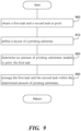
- FIG. 9 is a flowchart of a method to control the placement of a pattern around the borders of a print job.
- a processor can obtain a first task and a second task to print.
- the second task is different from and independent of the first task.
- the first task can be content or a print job provided by the user, while the second task can be a test pattern designed to test the performance of the printer, such as testing nozzle alignment, printhead alignment, nozzle clogging, ink intensity/uniformity, etc., as shown in FIGS. 3A-3B .
- the processor can run the instructions of the ROUS process.
- a processor can define a layout of a printing image including a center region configured to contain the first task, and a peripheral region configured to contain the second task, as shown in FIG. 1 .
- the layout can be modified as described in this application.
- the processor can determine an amount of printing substrate needed to print the first task.
- the amount of printing substrate can be a number of pages, an area of the printing substrate, length of the printing substrate, etc.
- the printing substrate can be paper, textile, plastic, etc.
- a page can be a maximum size on which the printer can print.
- the amount of printing substrate is a positive number.
- the processor can arrange the first task and the second task within the determined amount of printing substrate by dividing the second task into sub-tasks configured to fit within a number of peripheral regions associated with the determined number of pages.
- the processor can manipulate one of the sub-tasks to fit within the peripheral region of the printing substrate by rotating the sub-pattern, adjusting a size of the sub-task, adjusting an offset of the sub-task, cropping, or adjusting a byte alignment of the sub-task.
- the processor can distribute the sub-tasks containing the second task over one or more first tasks, i.e., one or more print jobs.
- the initial print job can offer a limited amount of space such as 10 pages, and the second task can contain 70 sub-tasks.
- the processor can automatically determine that within those 10 pages only 4 out of the 70 sub-tasks can be printed. Further, the processor can determine how to manipulate the 4 sub-tasks over the 10 pages.
- the processor Upon receiving the next print job, the processor can determine to print an additional 12 sub-tasks of the remaining 66 tasks.
- the processor can manipulate the 12 sub-tasks differently from the original 4 sub-tasks to, for example, reduce the amount of printing substrate used.
- the software can add metadata to each printed sub-pattern to indicate to the printer and a subsequent inspection system what sub-tasks are on each print job, to indicate where the sub-tasks are within each print job, to indicate a color associated with each sub-pattern, such as cyan, magenta or yellow, etc.
- the instructions of the subsequent inspection system can be also executed by the processor.
- the processor can reconstruct at least a portion of the second task based on metadata and the multiple received sub-tasks.
- the processor can inspect the reconstructed portion of the second task to detect if there is an error in printing, such as shown in FIGS. 4A-4B .
- the processor can determine a source of the error, such as misaligned nozzles, clogged nozzles, low ink, a misaligned printhead, etc.
- the processor can cause the error to be fixed by, for example, automatically fixing the error or notifying the user to fix the error.
- the processor can automatically detect an error in the first task.
- the processor can obtain the second task likely to identify a cause of the error.
- the processor can retrieve the second task from the database because the second task is associated with a similar error, or the processor can create a second task.
- the processor can print the second task to further test the printer. If the second task does not identify the cause of the problem, the process can be repeated iteratively, until the cause of the problem is identified and/or solved.
- the processor can notice that a cyan color has a mottled appearance. Consequently, the processor can determine that the nozzles printing cyan are nozzles 1-10 and can create the second task containing a shape of cyan color to be printed by the nozzles 1-10. However, the current print job does not have enough space to test all 10 nozzles. Consequently, the processor can determine to test only nozzle 1 when printing the current print job, nozzles 2 and 10 with a subsequent print job, nozzles 3, 5 and 9 in the subsequent job, etc.
- the processor can include metadata to indicate which nozzles are tested with which print job, because without the metadata, knowing which nozzle printed which cyan color is not possible.
- the processor can determine that nozzles 8 and 9 are misaligned. To automatically fix the problem, the processor can iteratively and incrementally adjust the positions of nozzles 8 and 9 and print out test patterns for just nozzles 8 and 9, until the positions of nozzles 8 and 9 are properly aligned.
- the processor can define at most two horizontal sections including a top section to be printed at the top of the printing image and a bottom section to be printed at a bottom of the printing image, and at most two vertical sections including a left section to be printed on a left side of the printing image and a right section to be printed on a right side of the printing image.
- Each horizontal and vertical section can include at most two fixed sub-sections and at most one variable sub-section positioned between the at most two fixed sub-sections.
- the processor can determine whether to enable at most two horizontal and at most two vertical sections.
- the processor can determine a size of each section among the two horizontal and the two vertical sections.
- the processor can determine a spacing between the two fixed sub-sections and the one variable sub-section.
- the processor can determine whether to enable one or more of the two fixed sub-sections and the one variable sub-section.
- the processor can determine a size of each enabled sub-section of the two fixed sub-sections and the one variable sub-section.
- the processor can determine an alignment of each enabled sub-section of the two fixed sub-sections and the one variable sub-section.
- the processor can determine a sub-task in the sub-tasks to associate with each enabled sub-section.
- the processor can also define: 1) if the pre-defined raster should be repeated within the sub-section, and if so, 2) the spacing between the repeated raster.
- the processor can determine whether to repeatedly print the sub-task. Upon determining to repeat the sub-task, the processor can determine a spacing between the repeatedly printed sub-tasks.
- the processor can determine whether a portion of the one or more first tasks occupies at least a portion of the peripheral region. Upon determining that the portion of the one or more first es at least the portion of the peripheral region, the processor can combine the second task with the portion of the one or more first tasks by overlaying, underlaying or stitching the second task and the portion of the one or more first tasks.
- the processor can obtain an indication of a separation between portions of the second task, such as 3 m, 5 pages, etc.
- the processor can measure a distance within the one or more first tasks. When the distance corresponds to the indicated separation between the portions of the second task, the processor can print an appropriate portion of the second task.
- FIG. 10 is a diagrammatic representation of a machine in the example form of a computer system 1000 within which a set of instructions, for causing the machine to perform any one or more of the methodologies or modules discussed herein, may be executed.
- the computer system 1000 includes a processor, memory, non-volatile memory, and an interface device. Various common components (e.g., cache memory) are omitted for illustrative simplicity.
- the computer system 1000 is intended to illustrate a hardware device on which any of the components described in the example of FIGS. 1- 9 (and any other components described in this specification) can be implemented.
- the computer system 1000 can be of any applicable known or convenient type.
- the components of the computer system 1000 can be coupled together via a bus or through some other known or convenient device.
- the processor of the computer system 1000 can execute the methods described in this application.
- the processor can execute the ROUS process.
- the main memory, the nonvolatile memory and/or the drive unit can store the instructions and can store the first and the second task.
- the processor can communicate with the printer and/or the inspection system using the network of computer system 1000.
- computer system 1000 may be an embedded computer system, a system-on-chip (SOC), a single-board computer system (SBC) (such as, for example, a computer-on-module (COM) or system-on-module (SOM)), a desktop computer system, a laptop or notebook computer system, an interactive kiosk, a mainframe, a mesh of computer systems, a mobile telephone, a personal digital assistant (PDA), a server, or a combination of two or more of these.
- SOC system-on-chip
- SBC single-board computer system
- COM computer-on-module
- SOM system-on-module
- computer system 1000 may include one or more computer systems 1000; be unitary or distributed; span multiple locations; span multiple machines; or reside in a cloud, which may include one or more cloud components in one or more networks.
- one or more computer systems 1000 may perform without substantial spatial or temporal limitation one or more steps of one or more methods described or illustrated herein.
- one or more computer systems 1000 may perform in real time or in batch mode one or more steps of one or more methods described or illustrated herein.
- One or more computer systems 1000 may perform at different times or at different locations one or more steps of one or more methods described or illustrated herein, where appropriate.
- the processor may be, for example, a conventional microprocessor such as an Intel Pentium microprocessor or Motorola power PC microprocessor.
- Intel Pentium microprocessor or Motorola power PC microprocessor.
- machine-readable (storage) medium or “computer-readable (storage) medium” include any type of device that is accessible by the processor.
- the memory is coupled to the processor by, for example, a bus.
- the memory can include, by way of example but not limitation, random access memory (RAM), such as dynamic RAM (DRAM) and static RAM (SRAM).
- RAM random access memory
- DRAM dynamic RAM
- SRAM static RAM
- the memory can be local, remote, or distributed.
- the bus also couples the processor to the non-volatile memory and drive unit.
- the nonvolatile memory is often a magnetic floppy or hard disk, a magnetic-optical disk, an optical disk, a read-only memory (ROM), such as a CD-ROM, EPROM, or EEPROM, a magnetic or optical card, or another form of storage for large amounts of data. Some of this data is often written, by a direct memory access process, into memory during execution of software in the computer 1000.
- the nonvolatile storage can be local, remote, or distributed.
- the non-volatile memory is optional because systems can be created with all applicable data available in memory.
- a typical computer system will usually include at least a processor, memory, and a device (e.g., a bus) coupling the memory to the processor.
- Software is typically stored in the non-volatile memory and/or the drive unit. Indeed, storing and entire large program in memory may not even be possible. Nevertheless, it should be understood that for software to run, if necessary, it is moved to a computer readable location appropriate for processing, and for illustrative purposes, that location is referred to as the memory in this paper. Even when software is moved to the memory for execution, the processor will typically make use of hardware registers to store values associated with the software, and local cache that, ideally, serves to speed up execution.
- a software program is assumed to be stored at any known or convenient location (from non-volatile storage to hardware registers) when the software program is referred to as “implemented in a computer-readable medium.”
- a processor is considered to be “configured to execute a program” when at least one value associated with the program is stored in a register readable by the processor.
- the bus also couples the processor to the network interface device.
- the interface can include one or more of a modem or network interface. It will be appreciated that a modem or network interface can be considered to be part of the computer system 1000.
- the interface can include an analog modem, ISDN modem, cable modem, token ring interface, satellite transmission interface (e.g. "direct PC"), or other interfaces for coupling a computer system to other computer systems.
- the interface can include one or more input and/or output devices.
- the I/O devices can include, by way of example but not limitation, a keyboard, a mouse or other pointing device, disk drives, printers, a scanner, and other input and/or output devices, including a display device.
- the display device can include, by way of example but not limitation, a cathode ray tube (CRT), liquid crystal display (LCD), or some other applicable known or convenient display device.
- CTR cathode ray tube
- LCD liquid crystal display
- controllers of any devices not depicted in the example of FIG. 10 reside in the interface.
- the computer system 1000 can be controlled by operating system software that includes a file management system, such as a disk operating system.
- operating system software with associated file management system software is the family of operating systems known as Windows ® from Microsoft Corporation of Redmond, Washington, and its associated file management systems.
- Windows TM operating system
- the file management system is typically stored in the non-volatile memory and/or drive unit and causes the processor to execute the various acts required by the operating system to input and output data and to store data in the memory, including storing files on the non-volatile memory and/or drive unit.
- the machine operates as a standalone device or may be connected (e.g., networked) to other machines.
- the machine may operate in the capacity of a server or a client machine in a client-server network environment, or as a peer machine in a peer-to-peer (or distributed) network environment.
- the machine may be a server computer, a client computer, a personal computer (PC), a tablet PC, a laptop computer, a set-top box (STB), a personal digital assistant (PDA), a cellular telephone, an iPhone, a Blackberry, a processor, a telephone, a web appliance, a network router, switch or bridge, or any machine capable of executing a set of instructions (sequential or otherwise) that specify actions to be taken by that machine.
- PC personal computer
- PDA personal digital assistant
- machine-readable medium or machine-readable storage medium is shown in an exemplary embodiment to be a single medium, the term “machine-readable medium” and “machine-readable storage medium” should be taken to include a single medium or multiple media (e.g., a centralized or distributed database, and/or associated caches and servers) that store the one or more sets of instructions.
- the term “machine-readable medium” and “machine-readable storage medium” shall also be taken to include any medium that is capable of storing, encoding or carrying a set of instructions for execution by the machine and that cause the machine to perform any one or more of the methodologies or modules of the presently disclosed techniques and innovation.
- routines executed to implement the embodiments of the disclosure may be implemented as part of an operating system or a specific application, component, program, object, module or sequence of instructions referred to as "computer programs.”
- the computer programs typically include one or more instructions set at various times in various memory and storage devices in a computer, and that, when read and executed by one or more processing units or processors in a computer, cause the computer to perform operations to execute elements involving the various aspects of the disclosure.
- machine-readable storage media machine-readable media, or computer-readable (storage) media
- recordable type media such as volatile and non-volatile memory devices, floppy and other removable disks, hard disk drives, optical disks (e.g., Compact Disk Read-Only Memory (CD ROMS), Digital Versatile Disks, (DVDs), etc.), among others, and transmission type media such as digital and analog communication links.
- CD ROMS Compact Disk Read-Only Memory
- DVDs Digital Versatile Disks
- transmission type media such as digital and analog communication links.
- operation of a memory device may include a transformation, such as a physical transformation.
- a transformation such as a physical transformation.
- a physical transformation may include a physical transformation of an article to a different state or thing.
- a change in state may involve an accumulation and storage of charge or a release of stored charge.
- a change of state may include a physical change or transformation in magnetic orientation or a physical change or transformation in molecular structure, such as from crystalline to amorphous or vice versa.
- a storage medium typically may be non-transitory or include a non-transitory device.
- a non-transitory storage medium may include a device that is tangible, meaning that the device has a concrete physical form, although the device may change its physical state.
- non-transitory refers to a device remaining tangible despite this change in state.
- the present invention provides a method comprising:
- the non-user generated pattern comprises a pattern to check a nozzle, or a pattern to check color uniformity.
- the present invention provides a method comprising:
- the method comprises manipulating a sub-task in the plurality of sub-tasks to fit within the peripheral region of the printing image.
- said manipulating comprising rotating, adjusting a size of the sub-task, adjusting an offset of the sub-task, cropping, or adjusting a byte alignment of the sub-task.
- the method comprises reconstructing at least a portion of the second task based on the plurality of sub-tasks.
- said defining the layout of the printing image comprises defining at most two horizontal sections comprising a top section to be printed at the top of the printing image and a bottom section to be printed at a bottom of the printing image and at most two vertical sections comprising a left section to be printed on a left side of the printing image and a right section to be printed on a right side of the printing image, wherein each horizontal and vertical section comprises at most two fixed sub-sections and at most one variable sub-section positioned between the at most two fixed sub-sections.
- the method comprises:
- the method comprises:
- the method comprises
- the second task comprises a pattern to check a nozzle, or a pattern to check color uniformity.
- the present invention provides a system comprising a processor configured to:
- the processor is configured to:
- the processor is configured to reconstruct at least a portion of the second task based on the plurality of sub-tasks.
- the processor is configured to define the layout of the printing image.
- the processor is configured to define at most two horizontal sections comprising a top section to be printed at the top of the printing image and a bottom section to be printed at a bottom of the printing image and at most two vertical sections comprising a left section to be printed on a left side of the printing image and a right section to be printed on a right side of the printing image, wherein each horizontal and vertical section comprises at most two fixed sub-sections and at most one variable sub-section positioned between the at most two fixed sub-sections.
- the processor is configured to:
- the processor is configured to:
- the processor is configured to:
- the processor is configured to manipulate a sub-task in the plurality of sub-tasks to fit within the peripheral region of the printing image.
- the processor is configured to manipulate comprising the processor configured to rotate, adjust a size of the sub-task, adjust an offset of the sub-task, crop, or adjust a byte alignment of the sub-task.
Landscapes
- Engineering & Computer Science (AREA)
- Multimedia (AREA)
- Signal Processing (AREA)
- General Engineering & Computer Science (AREA)
- Physics & Mathematics (AREA)
- General Physics & Mathematics (AREA)
- Theoretical Computer Science (AREA)
- Human Computer Interaction (AREA)
- Health & Medical Sciences (AREA)
- Biomedical Technology (AREA)
- General Health & Medical Sciences (AREA)
- Record Information Processing For Printing (AREA)
Claims (15)
- Verfahren, das folgende Schritte aufweist:Erhalten eines ersten Auftrags zum Drucken, eines zweiten Auftrags zum Drucken und eines Druckmodus, wobei sich der zweite Auftrag von dem ersten Auftrag unterscheidet und von diesem unabhängig ist;Definieren eines Layouts eines Druckbildes, das einen Mittelbereich, der dazu konfiguriert ist, den ersten Auftrag zu enthalten, und einen Randbereich aufweist, der dazu konfiguriert ist, den zweiten Auftrag zu enthalten;Auswählen zwischen Überlagern, Unterlegen und Zusammenheften des zweiten Auftrags und des ersten Auftrags basierend auf dem Druckmodus, wobei das Überlagern ein Drucken des zweiten Auftrags über den ersten Auftrag in dem Randbereich beinhaltet, das Unterlegen ein Drucken des zweiten Auftrags unter dem ersten Auftrag in dem Randbereich beinhaltet und das Zusammenheften ein Drucken des zweiten Auftrags um den ersten Auftrag in dem Randbereich beinhaltet;Bestimmen einer Anzahl von Druckbildern, die benötigt werden, um den ersten Auftrag zu drucken; undAnordnen des ersten Auftrags und des zweiten Auftrags innerhalb der bestimmten Anzahl von Druckbildern.
- Verfahren gemäß Anspruch 1, das folgende Schritte aufweist:Abbilden des zweiten Auftrags in eine Mehrzahl von Teilaufträgen, die dazu konfiguriert sind, in eine Anzahl von Randbereichen zu passen, die der bestimmten Anzahl von Bildern zugeordnet sind; undManipulieren eines Teilauftrags in der Mehrzahl von Teilaufträgen, um in den Randbereich des Druckbildes zu passen.
- Verfahren gemäß Anspruch 2, wobei das Manipulieren ein Drehen, ein Einstellen einer Größe des Teilauftrags, ein Einstellen eines Versatzes des Teilauftrags, ein Beschneiden oder ein Einstellen einer Byteausrichtung des Teilauftrags aufweist.
- Verfahren gemäß Anspruch 1, das folgende Schritte aufweist:Abbilden des zweiten Auftrags in eine Mehrzahl von Teilaufträgen, die dazu konfiguriert sind, in eine Anzahl von Randbereichen zu passen, die der bestimmten Anzahl von Bildern zugeordnet sind; undRekonstruieren zumindest eines Abschnitts des zweiten Auftrags basierend auf der Mehrzahl von Teilaufträgen.
- Verfahren gemäß Anspruch 1, wobei das Definieren des Layouts des Druckbildes folgenden Schritt aufweist:
Definieren von höchstens zwei horizontalen Abschnitten, die einen oberen Abschnitt, der oben auf das Druckbild gedruckt werden soll, und einen unteren Abschnitt aufweisen, der unten auf das Druckbild gedruckt werden soll, und höchstens zwei vertikalen Abschnitte, die einen linken Abschnitt, der auf eine linke Seite des Druckbildes gedruckt werden soll, und einen rechten Abschnitt aufweisen, der auf eine rechte Seite des Druckbildes gedruckt werden soll, wobei jeder horizontale und vertikale Abschnitt höchstens zwei feste Teilabschnitte und höchstens einen variablen Teilabschnitt aufweist, der zwischen den höchstens zwei festen Teilabschnitten positioniert ist. - Verfahren gemäß Anspruch 5, das folgende Schritte aufweist:Bestimmen, ob die höchstens zwei horizontalen und die höchstens zwei vertikalen Abschnitte aktiviert werden sollen;Bestimmen einer Größe jedes Abschnitts unter den höchstens zwei horizontalen und den höchstens zwei vertikalen Abschnitten; undBestimmen eines Abstands zwischen den höchstens zwei festen Teilabschnitten und dem höchstens einen variablen Teilabschnitt.
- Verfahren gemäß Anspruch 5, das folgende Schritte aufweist:Bestimmen, ob einer oder mehr der höchstens zwei festen Teilabschnitte und des höchstens einen variablen Teilabschnitts aktiviert werden sollen;Bestimmen einer Größe jedes aktivierten Teilabschnitts der höchstens zwei festen Teilabschnitte und des höchstens einen variablen Teilabschnitts;Bestimmen einer Ausrichtung jedes aktivierten Teilabschnitts der höchstens zwei festen Teilabschnitte und des höchstens einen variablen Teilabschnitts; undBestimmen eines Teilauftrags, der dem zweiten Auftrag zugeordnet ist, um jedem aktivierten Teilabschnitt zugeordnet zu werden.
- Verfahren gemäß Anspruch 5, das folgende Schritte aufweist:wenn ein Teilauftrag, der dem zweiten Auftrag zugeordnet ist, innerhalb des höchstens einen variablen Teilabschnitts gedruckt wird, Bestimmen, ob der Teilauftrag wiederholt gedruckt werden soll; undbeim Bestimmen, den Teilauftrag zu wiederholen, Bestimmen eines Abstands zwischen den wiederholt gedruckten Teilaufträgen.
- Verfahren gemäß Anspruch 1, wobei der zweite Auftrag ein Muster zum Prüfen einer Düse oder ein Muster zum Prüfen der Farbgleichförmigkeit aufweist.
- System, das einen Prozessor aufweist, der zu Folgendem konfiguriert ist:Erhalten eines oder mehrerer erster Aufträge zum Drucken, eines zweiten Auftrags zum Drucken und eines Druckmodus, wobei sich der zweite Auftrag von dem einen oder den mehr ersten Aufträgen unterscheidet und von diesen unabhängig ist;Definieren eines Layouts eines Druckbildes, das einen Mittelbereich, der dazu konfiguriert ist, den einen oder die mehr ersten Aufträge zu enthalten, und einen Randbereich aufweist, der dazu konfiguriert ist, den zweiten Auftrag zu enthalten;Auswählen zwischen Überlagern, Unterlegen und Zusammenheften des zweiten Auftrags und des einen oder der mehr ersten Aufträge basierend auf dem Druckmodus, wobei das Überlagern ein Drucken des zweiten Auftrags über den einen oder die mehr ersten Aufträge in dem Randbereich beinhaltet, das Unterlegen ein Drucken des zweiten Auftrags unter dem einen oder den mehr ersten Aufträgen in dem Randbereich beinhaltet und das Zusammenheften ein Drucken des zweiten Auftrags um den einen oder die mehr ersten Aufträge in dem Randbereich beinhaltet;Bestimmen einer Anzahl von Druckbildern, die benötigt werden, um den einen oder die mehr ersten Aufträge zu drucken; undAnordnen des einen oder der mehr ersten Aufträge und des zweiten Auftrags innerhalb der bestimmten Anzahl von Druckbildern.
- System gemäß Anspruch 10, das den Prozessor aufweist, der zu Folgendem konfiguriert ist:Bestimmen, ob ein Abschnitt des einen oder der mehr ersten Aufträge zumindest einen Abschnitt des Randbereichs belegt; undbeim Bestimmen, dass der Abschnitt des einen oder der mehr ersten Aufträge zumindest den Abschnitt des Randbereichs belegt, Kombinieren des zweiten Auftrags mit dem Abschnitt des einen oder der mehr ersten Aufträge, wobei das Kombinieren ein Überlagern, Unterlegen oder Zusammenheften des zweiten Auftrags und des Abschnitts des einen oder der mehr ersten Aufträge aufweist.
- System gemäß Anspruch 10, das den Prozessor aufweist, der zu Folgendem konfiguriert ist:Unterteilen des zweiten Auftrags in eine Mehrzahl von Teilaufträgen, die dazu konfiguriert sind, in eine Anzahl von Randbereichen zu passen, die der bestimmten Anzahl von Seiten zugeordnet sind; undRekonstruieren zumindest eines Abschnitts des zweiten Auftrags basierend auf der Mehrzahl von Teilaufträgen.
- System gemäß Anspruch 10, wobei der Prozessor dazu konfiguriert ist, das Layout des Druckbildes zu definieren, und der Prozessor zu Folgendem konfiguriert ist:
Definieren von höchstens zwei horizontalen Abschnitten, die einen oberen Abschnitt, der oben auf das Druckbild gedruckt werden soll, und einen unteren Abschnitt aufweisen, der unten auf das Druckbild gedruckt werden soll, und höchstens zwei vertikalen Abschnitten, die einen linken Abschnitt, der auf eine linke Seite des Druckbildes gedruckt werden soll, und einen rechten Abschnitt aufweisen, der auf eine rechte Seite des Druckbildes gedruckt werden soll, wobei jeder horizontale und vertikale Abschnitt höchstens zwei feste Teilabschnitte und höchstens einen variablen Teilabschnitt aufweist, der zwischen den höchstens zwei festen Teilabschnitten positioniert ist. - System gemäß Anspruch 10, das den Prozessor aufweist, der zu Folgendem konfiguriert ist:Erhalten einer Angabe einer Trennung zwischen Abschnitten des zweiten Auftrags;Messen eines Abstands innerhalb des einen oder der mehr ersten Aufträge; undwenn der Abstand der angegebenen Trennung zwischen den Abschnitten des zweiten Auftrags entspricht, Drucken eines geeigneten Abschnitts des zweiten Auftrags.
- System gemäß Anspruch 10, das den Prozessor aufweist, der dazu konfiguriert ist, einen Teilauftrag, der dem zweiten Auftrag zugeordnet ist, zu manipulieren, um in den Randbereich des Druckbildes zu passen.
Priority Applications (1)
| Application Number | Priority Date | Filing Date | Title |
|---|---|---|---|
| EP24206490.5A EP4489389A3 (de) | 2019-07-10 | 2020-07-09 | Drucken von nichtbenutzermustern mit einem druckauftrag |
Applications Claiming Priority (2)
| Application Number | Priority Date | Filing Date | Title |
|---|---|---|---|
| US16/507,584 US10929728B2 (en) | 2019-07-10 | 2019-07-10 | Printing non-user patterns with a print job |
| PCT/US2020/041448 WO2021007455A1 (en) | 2019-07-10 | 2020-07-09 | Printing non-user patterns with a print job |
Related Child Applications (1)
| Application Number | Title | Priority Date | Filing Date |
|---|---|---|---|
| EP24206490.5A Division EP4489389A3 (de) | 2019-07-10 | 2020-07-09 | Drucken von nichtbenutzermustern mit einem druckauftrag |
Publications (3)
| Publication Number | Publication Date |
|---|---|
| EP3997618A1 EP3997618A1 (de) | 2022-05-18 |
| EP3997618A4 EP3997618A4 (de) | 2023-07-26 |
| EP3997618B1 true EP3997618B1 (de) | 2024-10-16 |
Family
ID=74103180
Family Applications (2)
| Application Number | Title | Priority Date | Filing Date |
|---|---|---|---|
| EP24206490.5A Pending EP4489389A3 (de) | 2019-07-10 | 2020-07-09 | Drucken von nichtbenutzermustern mit einem druckauftrag |
| EP20837552.7A Active EP3997618B1 (de) | 2019-07-10 | 2020-07-09 | Drucken von nicht-benutzermustern mit einem druckauftrag |
Family Applications Before (1)
| Application Number | Title | Priority Date | Filing Date |
|---|---|---|---|
| EP24206490.5A Pending EP4489389A3 (de) | 2019-07-10 | 2020-07-09 | Drucken von nichtbenutzermustern mit einem druckauftrag |
Country Status (3)
| Country | Link |
|---|---|
| US (2) | US10929728B2 (de) |
| EP (2) | EP4489389A3 (de) |
| WO (1) | WO2021007455A1 (de) |
Families Citing this family (1)
| Publication number | Priority date | Publication date | Assignee | Title |
|---|---|---|---|---|
| IT202300021291A1 (it) * | 2023-10-12 | 2025-04-12 | Electronics For Imaging Inc | Sistema per stampa diretta su tessuti |
Family Cites Families (3)
| Publication number | Priority date | Publication date | Assignee | Title |
|---|---|---|---|---|
| JP4513573B2 (ja) * | 2005-01-11 | 2010-07-28 | セイコーエプソン株式会社 | 帳票処理装置 |
| DE102005041181A1 (de) | 2005-08-31 | 2007-05-10 | Man Roland Druckmaschinen Ag | Verfahren zur Erzeugung von Druckkontrollstreifen und Verfahren zur Regelung der Farbgebung unter Verwendung von Druckkontrollstreifen |
| JP6435744B2 (ja) * | 2014-09-24 | 2018-12-12 | 富士ゼロックス株式会社 | 画像形成装置及びプログラム |
-
2019
- 2019-07-10 US US16/507,584 patent/US10929728B2/en active Active
-
2020
- 2020-07-09 EP EP24206490.5A patent/EP4489389A3/de active Pending
- 2020-07-09 EP EP20837552.7A patent/EP3997618B1/de active Active
- 2020-07-09 WO PCT/US2020/041448 patent/WO2021007455A1/en not_active Ceased
-
2021
- 2021-02-22 US US17/181,069 patent/US11227200B2/en active Active
Also Published As
| Publication number | Publication date |
|---|---|
| WO2021007455A1 (en) | 2021-01-14 |
| EP4489389A2 (de) | 2025-01-08 |
| US11227200B2 (en) | 2022-01-18 |
| EP4489389A3 (de) | 2025-03-19 |
| US20210174156A1 (en) | 2021-06-10 |
| EP3997618A4 (de) | 2023-07-26 |
| EP3997618A1 (de) | 2022-05-18 |
| US20210012170A1 (en) | 2021-01-14 |
| US10929728B2 (en) | 2021-02-23 |
Similar Documents
| Publication | Publication Date | Title |
|---|---|---|
| US8094340B2 (en) | Printing system and method of operating same | |
| US10754598B2 (en) | Print controller, non-transitory computer-readable recording medium storing print control program and print control method | |
| US8851593B1 (en) | Image processing apparatus, image forming apparatus, non-transitory computer readable medium, and image processing method | |
| US20160086070A1 (en) | Image forming apparatus and non-transitory computer readable medium | |
| CN108931898A (zh) | 图像形成装置、图像形成系统、管理装置以及记录介质 | |
| JP5770580B2 (ja) | 印刷順序決定装置、印刷順序決定方法およびプログラム | |
| US11227200B2 (en) | Printing non-user patterns with a print job | |
| US8922830B2 (en) | Media roll management | |
| EP4056378B1 (de) | Dynamisches abtastqualitätskontrollmanagement für druckaufträge | |
| US8879117B2 (en) | Margin adjustment | |
| US8300289B2 (en) | Method for compensating for color variations across a printed page using multiple-pass printing | |
| US20060268287A1 (en) | Automated promotion of monochrome jobs for HLC production printers | |
| US11314465B1 (en) | Dynamic scan quality control management for print jobs | |
| JP2016146604A (ja) | 画像制御装置、印刷装置、およびプログラム | |
| US10688817B2 (en) | Printer configuration | |
| EP2827285B1 (de) | Bildverarbeitungssystem und -verfahren | |
| US20250165925A1 (en) | Proofreading assistance method and proofreading assistance system | |
| US12434471B2 (en) | Print defect seeding within selected zones for print verification system | |
| JP4706553B2 (ja) | 印刷制御装置、方法およびプログラム | |
| JP2025133364A (ja) | 情報処理装置、情報処理方法、及びプログラム | |
| US20170371603A1 (en) | Method and computer program product for generating output print data for printing multiple copies with at least one variable element on a print sheet | |
| JP4736914B2 (ja) | 印刷物の版管理をする電子フォーム印刷システム、方法、印刷媒体、コンピュータプログラム、および、記録媒体 | |
| WO2021126237A1 (en) | Printing with media roll changes and nonproduction frames | |
| US20120076514A1 (en) | Method and system to track unused media | |
| JP2014013442A (ja) | 印刷制御装置 |
Legal Events
| Date | Code | Title | Description |
|---|---|---|---|
| STAA | Information on the status of an ep patent application or granted ep patent |
Free format text: STATUS: THE INTERNATIONAL PUBLICATION HAS BEEN MADE |
|
| PUAI | Public reference made under article 153(3) epc to a published international application that has entered the european phase |
Free format text: ORIGINAL CODE: 0009012 |
|
| STAA | Information on the status of an ep patent application or granted ep patent |
Free format text: STATUS: REQUEST FOR EXAMINATION WAS MADE |
|
| 17P | Request for examination filed |
Effective date: 20220107 |
|
| AK | Designated contracting states |
Kind code of ref document: A1 Designated state(s): AL AT BE BG CH CY CZ DE DK EE ES FI FR GB GR HR HU IE IS IT LI LT LU LV MC MK MT NL NO PL PT RO RS SE SI SK SM TR |
|
| RAP3 | Party data changed (applicant data changed or rights of an application transferred) |
Owner name: ELECTRONICS FOR IMAGING, INC. |
|
| DAV | Request for validation of the european patent (deleted) | ||
| DAX | Request for extension of the european patent (deleted) | ||
| P01 | Opt-out of the competence of the unified patent court (upc) registered |
Effective date: 20230530 |
|
| A4 | Supplementary search report drawn up and despatched |
Effective date: 20230622 |
|
| RIC1 | Information provided on ipc code assigned before grant |
Ipc: H04N 1/387 20060101ALI20230619BHEP Ipc: H04N 1/00 20060101ALI20230619BHEP Ipc: H04N 1/393 20060101ALI20230619BHEP Ipc: H04N 1/40 20060101ALI20230619BHEP Ipc: G06K 15/00 20060101ALI20230619BHEP Ipc: G06K 15/02 20060101AFI20230619BHEP |
|
| RAP1 | Party data changed (applicant data changed or rights of an application transferred) |
Owner name: FIERY, LLC |
|
| GRAP | Despatch of communication of intention to grant a patent |
Free format text: ORIGINAL CODE: EPIDOSNIGR1 |
|
| STAA | Information on the status of an ep patent application or granted ep patent |
Free format text: STATUS: GRANT OF PATENT IS INTENDED |
|
| INTG | Intention to grant announced |
Effective date: 20240508 |
|
| GRAS | Grant fee paid |
Free format text: ORIGINAL CODE: EPIDOSNIGR3 |
|
| GRAA | (expected) grant |
Free format text: ORIGINAL CODE: 0009210 |
|
| STAA | Information on the status of an ep patent application or granted ep patent |
Free format text: STATUS: THE PATENT HAS BEEN GRANTED |
|
| AK | Designated contracting states |
Kind code of ref document: B1 Designated state(s): AL AT BE BG CH CY CZ DE DK EE ES FI FR GB GR HR HU IE IS IT LI LT LU LV MC MK MT NL NO PL PT RO RS SE SI SK SM TR |
|
| REG | Reference to a national code |
Ref country code: GB Ref legal event code: FG4D |
|
| REG | Reference to a national code |
Ref country code: DE Ref legal event code: R096 Ref document number: 602020039674 Country of ref document: DE Ref country code: CH Ref legal event code: EP |
|
| REG | Reference to a national code |
Ref country code: IE Ref legal event code: FG4D |
|
| REG | Reference to a national code |
Ref country code: LT Ref legal event code: MG9D |
|
| REG | Reference to a national code |
Ref country code: NL Ref legal event code: MP Effective date: 20241016 |
|
| REG | Reference to a national code |
Ref country code: AT Ref legal event code: MK05 Ref document number: 1733511 Country of ref document: AT Kind code of ref document: T Effective date: 20241016 |
|
| PG25 | Lapsed in a contracting state [announced via postgrant information from national office to epo] |
Ref country code: NL Free format text: LAPSE BECAUSE OF FAILURE TO SUBMIT A TRANSLATION OF THE DESCRIPTION OR TO PAY THE FEE WITHIN THE PRESCRIBED TIME-LIMIT Effective date: 20241016 |
|
| PG25 | Lapsed in a contracting state [announced via postgrant information from national office to epo] |
Ref country code: NL Free format text: LAPSE BECAUSE OF FAILURE TO SUBMIT A TRANSLATION OF THE DESCRIPTION OR TO PAY THE FEE WITHIN THE PRESCRIBED TIME-LIMIT Effective date: 20241016 |
|
| PG25 | Lapsed in a contracting state [announced via postgrant information from national office to epo] |
Ref country code: IS Free format text: LAPSE BECAUSE OF FAILURE TO SUBMIT A TRANSLATION OF THE DESCRIPTION OR TO PAY THE FEE WITHIN THE PRESCRIBED TIME-LIMIT Effective date: 20250216 Ref country code: HR Free format text: LAPSE BECAUSE OF FAILURE TO SUBMIT A TRANSLATION OF THE DESCRIPTION OR TO PAY THE FEE WITHIN THE PRESCRIBED TIME-LIMIT Effective date: 20241016 Ref country code: PT Free format text: LAPSE BECAUSE OF FAILURE TO SUBMIT A TRANSLATION OF THE DESCRIPTION OR TO PAY THE FEE WITHIN THE PRESCRIBED TIME-LIMIT Effective date: 20250217 |
|
| PG25 | Lapsed in a contracting state [announced via postgrant information from national office to epo] |
Ref country code: FI Free format text: LAPSE BECAUSE OF FAILURE TO SUBMIT A TRANSLATION OF THE DESCRIPTION OR TO PAY THE FEE WITHIN THE PRESCRIBED TIME-LIMIT Effective date: 20241016 |
|
| PG25 | Lapsed in a contracting state [announced via postgrant information from national office to epo] |
Ref country code: BG Free format text: LAPSE BECAUSE OF FAILURE TO SUBMIT A TRANSLATION OF THE DESCRIPTION OR TO PAY THE FEE WITHIN THE PRESCRIBED TIME-LIMIT Effective date: 20241016 |
|
| PG25 | Lapsed in a contracting state [announced via postgrant information from national office to epo] |
Ref country code: ES Free format text: LAPSE BECAUSE OF FAILURE TO SUBMIT A TRANSLATION OF THE DESCRIPTION OR TO PAY THE FEE WITHIN THE PRESCRIBED TIME-LIMIT Effective date: 20241016 |
|
| PG25 | Lapsed in a contracting state [announced via postgrant information from national office to epo] |
Ref country code: NO Free format text: LAPSE BECAUSE OF FAILURE TO SUBMIT A TRANSLATION OF THE DESCRIPTION OR TO PAY THE FEE WITHIN THE PRESCRIBED TIME-LIMIT Effective date: 20250116 |
|
| PG25 | Lapsed in a contracting state [announced via postgrant information from national office to epo] |
Ref country code: LV Free format text: LAPSE BECAUSE OF FAILURE TO SUBMIT A TRANSLATION OF THE DESCRIPTION OR TO PAY THE FEE WITHIN THE PRESCRIBED TIME-LIMIT Effective date: 20241016 Ref country code: GR Free format text: LAPSE BECAUSE OF FAILURE TO SUBMIT A TRANSLATION OF THE DESCRIPTION OR TO PAY THE FEE WITHIN THE PRESCRIBED TIME-LIMIT Effective date: 20250117 Ref country code: AT Free format text: LAPSE BECAUSE OF FAILURE TO SUBMIT A TRANSLATION OF THE DESCRIPTION OR TO PAY THE FEE WITHIN THE PRESCRIBED TIME-LIMIT Effective date: 20241016 |
|
| PG25 | Lapsed in a contracting state [announced via postgrant information from national office to epo] |
Ref country code: PL Free format text: LAPSE BECAUSE OF FAILURE TO SUBMIT A TRANSLATION OF THE DESCRIPTION OR TO PAY THE FEE WITHIN THE PRESCRIBED TIME-LIMIT Effective date: 20241016 |
|
| PG25 | Lapsed in a contracting state [announced via postgrant information from national office to epo] |
Ref country code: RS Free format text: LAPSE BECAUSE OF FAILURE TO SUBMIT A TRANSLATION OF THE DESCRIPTION OR TO PAY THE FEE WITHIN THE PRESCRIBED TIME-LIMIT Effective date: 20250116 |
|
| PG25 | Lapsed in a contracting state [announced via postgrant information from national office to epo] |
Ref country code: SM Free format text: LAPSE BECAUSE OF FAILURE TO SUBMIT A TRANSLATION OF THE DESCRIPTION OR TO PAY THE FEE WITHIN THE PRESCRIBED TIME-LIMIT Effective date: 20241016 |
|
| PG25 | Lapsed in a contracting state [announced via postgrant information from national office to epo] |
Ref country code: DK Free format text: LAPSE BECAUSE OF FAILURE TO SUBMIT A TRANSLATION OF THE DESCRIPTION OR TO PAY THE FEE WITHIN THE PRESCRIBED TIME-LIMIT Effective date: 20241016 |
|
| PGFP | Annual fee paid to national office [announced via postgrant information from national office to epo] |
Ref country code: GB Payment date: 20250522 Year of fee payment: 6 |
|
| REG | Reference to a national code |
Ref country code: DE Ref legal event code: R097 Ref document number: 602020039674 Country of ref document: DE |
|
| PG25 | Lapsed in a contracting state [announced via postgrant information from national office to epo] |
Ref country code: EE Free format text: LAPSE BECAUSE OF FAILURE TO SUBMIT A TRANSLATION OF THE DESCRIPTION OR TO PAY THE FEE WITHIN THE PRESCRIBED TIME-LIMIT Effective date: 20241016 |
|
| PG25 | Lapsed in a contracting state [announced via postgrant information from national office to epo] |
Ref country code: RO Free format text: LAPSE BECAUSE OF FAILURE TO SUBMIT A TRANSLATION OF THE DESCRIPTION OR TO PAY THE FEE WITHIN THE PRESCRIBED TIME-LIMIT Effective date: 20241016 |
|
| PG25 | Lapsed in a contracting state [announced via postgrant information from national office to epo] |
Ref country code: SK Free format text: LAPSE BECAUSE OF FAILURE TO SUBMIT A TRANSLATION OF THE DESCRIPTION OR TO PAY THE FEE WITHIN THE PRESCRIBED TIME-LIMIT Effective date: 20241016 |
|
| PG25 | Lapsed in a contracting state [announced via postgrant information from national office to epo] |
Ref country code: CZ Free format text: LAPSE BECAUSE OF FAILURE TO SUBMIT A TRANSLATION OF THE DESCRIPTION OR TO PAY THE FEE WITHIN THE PRESCRIBED TIME-LIMIT Effective date: 20241016 |
|
| PG25 | Lapsed in a contracting state [announced via postgrant information from national office to epo] |
Ref country code: IT Free format text: LAPSE BECAUSE OF FAILURE TO SUBMIT A TRANSLATION OF THE DESCRIPTION OR TO PAY THE FEE WITHIN THE PRESCRIBED TIME-LIMIT Effective date: 20241016 |
|
| PLBE | No opposition filed within time limit |
Free format text: ORIGINAL CODE: 0009261 |
|
| STAA | Information on the status of an ep patent application or granted ep patent |
Free format text: STATUS: NO OPPOSITION FILED WITHIN TIME LIMIT |
|
| PG25 | Lapsed in a contracting state [announced via postgrant information from national office to epo] |
Ref country code: SE Free format text: LAPSE BECAUSE OF FAILURE TO SUBMIT A TRANSLATION OF THE DESCRIPTION OR TO PAY THE FEE WITHIN THE PRESCRIBED TIME-LIMIT Effective date: 20241016 |
|
| 26N | No opposition filed |
Effective date: 20250717 |
|
| PGFP | Annual fee paid to national office [announced via postgrant information from national office to epo] |
Ref country code: DE Payment date: 20250521 Year of fee payment: 6 |
|
| REG | Reference to a national code |
Ref country code: CH Ref legal event code: H13 Free format text: ST27 STATUS EVENT CODE: U-0-0-H10-H13 (AS PROVIDED BY THE NATIONAL OFFICE) Effective date: 20260224 |
|
| PG25 | Lapsed in a contracting state [announced via postgrant information from national office to epo] |
Ref country code: LU Free format text: LAPSE BECAUSE OF NON-PAYMENT OF DUE FEES Effective date: 20250709 |
|
| REG | Reference to a national code |
Ref country code: BE Ref legal event code: MM Effective date: 20250731 |
|
| PG25 | Lapsed in a contracting state [announced via postgrant information from national office to epo] |
Ref country code: BE Free format text: LAPSE BECAUSE OF NON-PAYMENT OF DUE FEES Effective date: 20250731 |
|
| PG25 | Lapsed in a contracting state [announced via postgrant information from national office to epo] |
Ref country code: FR Free format text: LAPSE BECAUSE OF NON-PAYMENT OF DUE FEES Effective date: 20250731 |
|
| PG25 | Lapsed in a contracting state [announced via postgrant information from national office to epo] |
Ref country code: CH Free format text: LAPSE BECAUSE OF NON-PAYMENT OF DUE FEES Effective date: 20250731 |