EP3997337B1 - Pump device - Google Patents
Pump device Download PDFInfo
- Publication number
- EP3997337B1 EP3997337B1 EP20736625.3A EP20736625A EP3997337B1 EP 3997337 B1 EP3997337 B1 EP 3997337B1 EP 20736625 A EP20736625 A EP 20736625A EP 3997337 B1 EP3997337 B1 EP 3997337B1
- Authority
- EP
- European Patent Office
- Prior art keywords
- piston
- cylinder
- heat
- working fluid
- cylinders
- Prior art date
- Legal status (The legal status is an assumption and is not a legal conclusion. Google has not performed a legal analysis and makes no representation as to the accuracy of the status listed.)
- Active
Links
- 239000012530 fluid Substances 0.000 claims description 61
- 238000010438 heat treatment Methods 0.000 claims description 54
- 238000005086 pumping Methods 0.000 claims description 38
- 239000007788 liquid Substances 0.000 claims description 36
- XLYOFNOQVPJJNP-UHFFFAOYSA-N water Substances O XLYOFNOQVPJJNP-UHFFFAOYSA-N 0.000 claims description 20
- 238000001816 cooling Methods 0.000 claims description 18
- 238000003973 irrigation Methods 0.000 claims description 7
- 230000002262 irrigation Effects 0.000 claims description 7
- 230000008878 coupling Effects 0.000 claims description 5
- 238000010168 coupling process Methods 0.000 claims description 5
- 238000005859 coupling reaction Methods 0.000 claims description 5
- 230000010355 oscillation Effects 0.000 claims description 2
- 238000006073 displacement reaction Methods 0.000 claims 2
- 230000007246 mechanism Effects 0.000 description 6
- 230000008901 benefit Effects 0.000 description 4
- 238000000034 method Methods 0.000 description 4
- 239000000126 substance Substances 0.000 description 4
- 239000000203 mixture Substances 0.000 description 3
- 239000000110 cooling liquid Substances 0.000 description 2
- 239000003673 groundwater Substances 0.000 description 2
- 238000012423 maintenance Methods 0.000 description 2
- 230000008569 process Effects 0.000 description 2
- 238000003287 bathing Methods 0.000 description 1
- 238000009835 boiling Methods 0.000 description 1
- 230000008859 change Effects 0.000 description 1
- 238000002485 combustion reaction Methods 0.000 description 1
- 230000007547 defect Effects 0.000 description 1
- 238000009795 derivation Methods 0.000 description 1
- 239000006185 dispersion Substances 0.000 description 1
- 239000003651 drinking water Substances 0.000 description 1
- 235000020188 drinking water Nutrition 0.000 description 1
- 230000005611 electricity Effects 0.000 description 1
- 230000007613 environmental effect Effects 0.000 description 1
- 238000012544 monitoring process Methods 0.000 description 1
- 230000005855 radiation Effects 0.000 description 1
- 238000003860 storage Methods 0.000 description 1
- 238000002604 ultrasonography Methods 0.000 description 1
- 238000010792 warming Methods 0.000 description 1
Images


Classifications
-
- F—MECHANICAL ENGINEERING; LIGHTING; HEATING; WEAPONS; BLASTING
- F03—MACHINES OR ENGINES FOR LIQUIDS; WIND, SPRING, OR WEIGHT MOTORS; PRODUCING MECHANICAL POWER OR A REACTIVE PROPULSIVE THRUST, NOT OTHERWISE PROVIDED FOR
- F03G—SPRING, WEIGHT, INERTIA OR LIKE MOTORS; MECHANICAL-POWER PRODUCING DEVICES OR MECHANISMS, NOT OTHERWISE PROVIDED FOR OR USING ENERGY SOURCES NOT OTHERWISE PROVIDED FOR
- F03G6/00—Devices for producing mechanical power from solar energy
- F03G6/06—Devices for producing mechanical power from solar energy with solar energy concentrating means
- F03G6/068—Devices for producing mechanical power from solar energy with solar energy concentrating means having other power cycles, e.g. Stirling or transcritical, supercritical cycles; combined with other power sources, e.g. wind, gas or nuclear
-
- F—MECHANICAL ENGINEERING; LIGHTING; HEATING; WEAPONS; BLASTING
- F04—POSITIVE - DISPLACEMENT MACHINES FOR LIQUIDS; PUMPS FOR LIQUIDS OR ELASTIC FLUIDS
- F04B—POSITIVE-DISPLACEMENT MACHINES FOR LIQUIDS; PUMPS
- F04B9/00—Piston machines or pumps characterised by the driving or driven means to or from their working members
- F04B9/08—Piston machines or pumps characterised by the driving or driven means to or from their working members the means being fluid
- F04B9/12—Piston machines or pumps characterised by the driving or driven means to or from their working members the means being fluid the fluid being elastic, e.g. steam or air
- F04B9/129—Piston machines or pumps characterised by the driving or driven means to or from their working members the means being fluid the fluid being elastic, e.g. steam or air having plural pumping chambers
- F04B9/131—Piston machines or pumps characterised by the driving or driven means to or from their working members the means being fluid the fluid being elastic, e.g. steam or air having plural pumping chambers with two mechanically connected pumping members
- F04B9/135—Piston machines or pumps characterised by the driving or driven means to or from their working members the means being fluid the fluid being elastic, e.g. steam or air having plural pumping chambers with two mechanically connected pumping members reciprocating movement of the pumping members being obtained by two single-acting elastic-fluid motors, each acting in one direction
-
- F—MECHANICAL ENGINEERING; LIGHTING; HEATING; WEAPONS; BLASTING
- F03—MACHINES OR ENGINES FOR LIQUIDS; WIND, SPRING, OR WEIGHT MOTORS; PRODUCING MECHANICAL POWER OR A REACTIVE PROPULSIVE THRUST, NOT OTHERWISE PROVIDED FOR
- F03G—SPRING, WEIGHT, INERTIA OR LIKE MOTORS; MECHANICAL-POWER PRODUCING DEVICES OR MECHANISMS, NOT OTHERWISE PROVIDED FOR OR USING ENERGY SOURCES NOT OTHERWISE PROVIDED FOR
- F03G6/00—Devices for producing mechanical power from solar energy
- F03G6/06—Devices for producing mechanical power from solar energy with solar energy concentrating means
-
- F—MECHANICAL ENGINEERING; LIGHTING; HEATING; WEAPONS; BLASTING
- F04—POSITIVE - DISPLACEMENT MACHINES FOR LIQUIDS; PUMPS FOR LIQUIDS OR ELASTIC FLUIDS
- F04B—POSITIVE-DISPLACEMENT MACHINES FOR LIQUIDS; PUMPS
- F04B1/00—Multi-cylinder machines or pumps characterised by number or arrangement of cylinders
- F04B1/02—Multi-cylinder machines or pumps characterised by number or arrangement of cylinders having two cylinders
-
- F—MECHANICAL ENGINEERING; LIGHTING; HEATING; WEAPONS; BLASTING
- F04—POSITIVE - DISPLACEMENT MACHINES FOR LIQUIDS; PUMPS FOR LIQUIDS OR ELASTIC FLUIDS
- F04B—POSITIVE-DISPLACEMENT MACHINES FOR LIQUIDS; PUMPS
- F04B17/00—Pumps characterised by combination with, or adaptation to, specific driving engines or motors
- F04B17/006—Solar operated
-
- Y—GENERAL TAGGING OF NEW TECHNOLOGICAL DEVELOPMENTS; GENERAL TAGGING OF CROSS-SECTIONAL TECHNOLOGIES SPANNING OVER SEVERAL SECTIONS OF THE IPC; TECHNICAL SUBJECTS COVERED BY FORMER USPC CROSS-REFERENCE ART COLLECTIONS [XRACs] AND DIGESTS
- Y02—TECHNOLOGIES OR APPLICATIONS FOR MITIGATION OR ADAPTATION AGAINST CLIMATE CHANGE
- Y02E—REDUCTION OF GREENHOUSE GAS [GHG] EMISSIONS, RELATED TO ENERGY GENERATION, TRANSMISSION OR DISTRIBUTION
- Y02E10/00—Energy generation through renewable energy sources
- Y02E10/40—Solar thermal energy, e.g. solar towers
- Y02E10/46—Conversion of thermal power into mechanical power, e.g. Rankine, Stirling or solar thermal engines
Definitions
- the invention relates to a pumping device, in particular for pumping water, with at least a first cylinder and a second cylinder, in each of which a piston with a piston rod connected thereto is slidably guided, each of the cylinders having a front end and a rear end, wherein the piston rods each emerge from the cylinders at the rear end and are coupled to one another in such a way that moving the piston of one of the cylinders towards the rear end of this cylinder causes the piston of the other cylinder to move towards its front end and vice versa, and in each case in Area of the rear end leads at least one line connection into each of the cylinders.
- Double piston pumps are well known and - unlike single piston pumps - ensure a substantially continuous flow of liquid when pumping a liquid.
- the piston rods connected to the pistons are moved back and forth in opposite directions via a drive.
- the drive can be done manually, for example by a hand lever mechanism, or via a motor, for example an electric motor.
- Pumps that can be operated autonomously, i.e. without being connected to a power grid, are used in a wide variety of areas. For example, they are used in irrigation systems where the pumps are used to draw water via a pipe system from a reservoir, such as a tank, a lake or groundwater. suck it in and deliver it to plants via a distribution device or distribute it over an area.
- a reservoir such as a tank, a lake or groundwater.
- Hand-operated pumps are essentially self-sufficient, although operating such pumps is physically demanding and requires the presence of a person operating the pump on site.
- Self-sufficient pumps powered by motors such as electric motors or internal combustion engines require an independent power supply, making them relatively unsuitable for continuous operation over several days or weeks.
- motors such as electric motors or internal combustion engines
- Such engines are prone to failure and therefore need to be serviced at regular intervals.
- the invention is therefore based on the object of providing a pump device of the type mentioned at the outset which does not have the disadvantages of the prior art.
- a pump suitable for continuous operation should be provided which can be operated automatically, but without the use of a fault-prone motor.
- a working fluid to which heat can be supplied via a heating device in the area of the front end, is accommodated in the cylinders between the piston and the front end, and that the supply of heat is controlled by a control device in such a way that Heat supply to the working fluid of one cylinder is interrupted is while heat is supplied to the working fluid of the other cylinder, and vice versa.
- the double pump can be operated without the help of an additional motor or a person operating the pump.
- control device is coupled to the pistons or piston rods in such a way that for each of the cylinders, when the piston guided therein is moved to the rear end, the heat supply to the working fluid of this cylinder is interrupted and when the piston is moved The heat supply to the front end of the piston is released.
- the pumping device can be operated in a substantially continuous pumping operation.
- control of the supply of heat can be independent of the position of the pistons.
- the heat supply can change between the cylinders periodically, i.e. following a specific time cycle.
- Embodiments in which the heating device provides the heat with the help of solar energy are particularly preferred. This allows the pumping device to be operated completely independently for longer periods of time. It is particularly advantageous if the pump device according to the invention is used in an irrigation system, since a lot of watering has to be done when there is strong sunlight, but at the same time there is enough solar energy available to cover the necessary energy requirements.
- Embodiments are also possible within the scope of the invention in which the heating device instead or additionally provides the heat with the help of wind power, for example via a wind turbine, and/or hydropower, for example via a water wheel, and/or geothermal energy.
- wind power for example via a wind turbine
- hydropower for example via a water wheel
- geothermal energy for example via a water wheel
- the heating device has an electrically operated heating element arranged at the front end of the respective cylinder, and that the power supply to the heating element can be interrupted or produced by the control device.
- This has the advantage that the power supply and therefore also heat supply can be interrupted quickly and without great design effort or additional moving components, for example via switches. Heating elements can heat up very quickly and also cool down quickly, so that a Pumping device according to this embodiment can be operated with a relatively high pumping frequency.
- the heating element has a heating coil arranged at or in the front end, which is fed with electrical current from outside the cylinder (e.g. generated with the help of solar cells) and which protrudes into the interior area of the cylinder filled with the working fluid.
- the heating element to supply heat to the working fluid using high-frequency vibration(s) (in particular ultrasound).
- the heating element has, for example, an oscillating element that can be arranged in the area of the working fluid or brought into contact with the working fluid and can be set into oscillation in such a way that heat is thereby supplied to the working fluid.
- the working fluid can be heated very effectively and quickly, for example by supplying electrical power obtained from solar energy.
- the heating device has a movable heating element which can be arranged at the front end or removed from the front end by the control device. Heat can thus be supplied to the working fluid from the heating element via the front end, whereby the supply of heat can be interrupted by removing the heating element.
- the heating element of a pump device designed in this way can be heated, for example, electrically (in particular via solar power) or thermally (in particular via water heated by solar radiation).
- the advantage of this embodiment is that the heating element does not have to be heated and cooled separately, and that heat can be supplied to the working fluid very quickly by arranging and removing the heating element at the front end or the heat supply can be interrupted.
- the heating device of each cylinder has at least one collecting element with which sun rays can be fed to the front end in a bundled or concentrated form. This causes the cylinder to heat up in the area of its front end and heat is supplied to the working fluid.
- the supply of solar rays - and thus the provision of heat to the working fluid - can be interrupted by the control device. What is particularly advantageous is that such an embodiment rarely requires maintenance because it is hardly susceptible to errors or defects.
- the collecting element is, for example, a concave mirror that focuses the sun's rays onto the front end. It is also conceivable that the collecting element is a lens that focuses the sun's rays onto the front end.
- the control device can place a shield or aperture between the mirror or lens and the front end, for example by pivoting the shield. However, it is also conceivable that the mirror or lens itself is adjusted, e.g. pivoted, so that the sun's rays are not directed towards the front end.
- the heating device can also have several mirrors or lenses or a combination of mirrors and lenses. Furthermore, the sun's rays do not necessarily have to be supplied directly to the front end, but can, for example, heat a liquid in a liquid circuit connected to the front end.
- control device can be coupled mechanically to the pistons or piston rods, in particular via a linkage and/or gears and/or belts and/or a cable pull.
- Such connections are particularly robust against environmental influences and have a long shelf life.
- the control device can also drive servomotors, which, for example, switch switches on or off or fold shields in or out.
- a cooling device is arranged at a distance from the front end on or around each of the cylinders, with which heat can be removed from the working fluid.
- the cooling device is spaced at least a quarter or a third of the total length of the cylinder from its front end.
- the piston must first travel a certain distance towards the rear end before the working fluid comes into contact with the section of the cylinder wall cooled by the cooling device.
- the cooling device allows heat to be removed particularly quickly from the heated and thereby expanded working fluid, so that it cools down more quickly and contracts more quickly or can be pressed together with less effort.
- the cooling device of each cylinder has, for example, at least one line surrounding the respective cylinder, through which a cooling liquid is passed.
- This cooling liquid can be part of the pump liquid, which is passed over the cooling devices when the pump liquid is pressed out of the cylinders. Additionally or instead, the cooling device can have cooling fins.
- Embodiments are preferred in which the working fluid is at least partially gaseous when heat is supplied and at least partially liquid when heat is removed.
- the working fluid can be a substance that is liquid at room temperature and that evaporates when heat is supplied and turns into a gaseous state.
- Such fluids have a high thermal expansion and can easily be filled into the cylinders or stored in the cylinders in the liquid state.
- the working fluid is essentially liquid when heat is supplied and removed or in which the working fluid is essentially gaseous when heat is supplied and removed.
- the working fluid can be a pure substance, for example a substantially pure substance that is liquid at room temperature, a pure gas or a mixture of two or more substances (gas mixture, dispersion, liquid mixture).
- a negative pressure in the cylinder between the piston and the front end when the piston of the respective cylinder is arranged in an end position in the area of the front end and the working fluid is in an unexpanded state.
- the negative pressure supports the movement of the piston towards the front end.
- the piston of this Cylinder is then not only influenced by the pressure force of the expanding working fluid of the other cylinder (transmitted to it via the piston of the other cylinder and the coupled piston rods), but also by the ambient pressure (which is higher than the negative pressure in the working chamber of the cylinder). moved from the rear to the front end of the cylinder.
- the pumping device can therefore be used to pump faster and more effectively.
- the piston is in its end position in the area of the front end - i.e. in a position in the cylinder in which the piston cannot be moved further towards the front end - not directly on the front end.
- an inner shoulder can be provided in the cylinder, against which the piston rests in its end position.
- the piston rod can only be retracted into the cylinder up to a certain length (e.g. due to a transverse flange arranged on it).
- the cylinders are aligned in the same way, in particular arranged next to one another.
- aligned in the same way means that the front end of one cylinder is arranged on the same side as the front end of the other cylinder. With such an arrangement, heat only needs to be supplied to the cylinders from one side.
- the cylinders are aligned in opposite directions, in particular arranged in a line.
- the piston rods can be coupled to one another particularly easily (e.g. directly).
- piston rods are coupled to one another via a movable linkage and/or gears and/or belts and/or a cable pull.
- a coupling enables the pistons or piston rods to be moved in opposite directions in a simple manner, particularly when cylinders are arranged next to one another.
- the piston rods are directly coupled to one another via a substantially rigid coupling or a rigid linkage or are each a partial section of a single piston rod connecting the pistons of both cylinders.
- a coupling mechanism with additional, moving parts can be dispensed with.
- the intermediate line can be connected (for example via a flow switch) to a supply line, via which a pump liquid can be sucked in, and a discharge line, via which the pump liquid can be drained away.
- a flow switch for example a flow switch
- a discharge line via which the pump liquid can be drained away.
- at least two line connections are present.
- one of the line connections can be connected to a supply line through which a pump liquid can be sucked in
- the other of the line connections can be connected to a discharge line through which the pump liquid can be drained away.
- a first check valve blocks the supply line when the piston is moved to the rear end
- a second check valve blocks the discharge line when the piston is moved to the front end.
- check valves are cheaper and require less maintenance than controlled valves.
- the valves can, for example - if present - be arranged in the intermediate line, in the outgoing and incoming lines or, if necessary, in the line connections.
- piston rods are mechanically connected to at least one further device in such a way that this further device can be driven or operated by the movement of the piston rods.
- the further device can be, for example, a rod pump, with the help of which water or another liquid can be conveyed to the surface from a great depth (for example from a depth of over 100 m). It is also conceivable that the further device is a generator for generating electrical current.
- the invention also relates to an irrigation device which has at least one pump device according to the invention. Furthermore, the irrigation device has at least one supply line via which the pumping device(s) can be connected to a water reservoir, at least one water distribution device and at least one discharge line via which the pumping device(s) is/are connected to the water distribution device(s).
- the water reservoir can be, for example, a pond, a lake, groundwater or an artificial tank or basin.
- the irrigation device has at least one solar panel for generating electrical current.
- the electricity generated can be used in particular to operate the Control device and/or the heating device, but also for monitoring or control electronics and/or for charging a buffer current storage device.
- a method for operating a pump device can also be provided, whereby this method can have selected or all features of a pump device according to the invention - as described above.
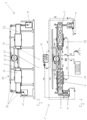
- the Fig. 1 and 2 show a pump device 1 according to the invention according to a first embodiment, in which the heat necessary to operate the pump device 1 is provided with the help of solar power.
- the pump device 1 has a first cylinder 2A and a second cylinder 2B, which are essentially aligned in the same way and arranged parallel to one another.
- a piston 3 is guided in each of the cylinders 2A, 2B and is connected to an associated piston rod 4.
- Each of the cylinders 2A, 2B has a front end 5 and a rear end 6, a working chamber 7 being formed between the piston 3 and the front end 5 and a pump chamber 8 being formed between the piston 3 and the rear end 6.
- a working fluid 9 is accommodated in the working chamber 7 of each cylinder 2A, 2B, which expands when heat is supplied, moves the respective piston 3 towards the rear end 6 and thus increases the volume of the working chamber 7.
- an inner shoulder 10 is formed in the cylinder 2A, 2B, against which the piston 3 rests in its end position - in which it cannot be pushed further towards the front end 5.
- the working chamber 7 of a cylinder 2A, 2B therefore has the smallest possible volume when the piston 3 is in the end position.
- Heat can be supplied to the working fluid 9 via a heating device 11 provided for this purpose in the area of the front end 5 of each cylinder 2A, 2B.
- the heating devices 11 have electrical heating elements, the heating coils 12 of which protrude into the working chambers 7.
- the heating devices 11 - and thus the heating coils 12 - are supplied with electrical current via power connections 13, so that the heating coils 12 through which the current flows supply heat to the working fluid 9.
- the power connections 13 are connected via power lines 14 to a solar panel 15, which generates solar power.
- the piston rods 4 of the cylinders 2A, 2B are coupled to one another via a pivotable linkage 16 in such a way that when one piston rod 4 is extended, the other piston rod 4 is automatically retracted and vice versa. Accordingly, the piston 3 of the first cylinder 2A also moves toward the front end 5 when the piston 3 of the second cylinder 2B is displaced toward the rear end 6 by the expanding working fluid 9 and vice versa.
- the pump chamber 8 of each cylinder 2A, 2B has two line connections 17.
- One of the line connections 17 is each connected via a supply line 18 to a liquid reservoir, in particular a water reservoir 19, of a pump liquid 20.
- the other line connection 17 is each connected via a discharge line 21 to a liquid distribution device, in particular a water distribution device 22, for distributing or dispensing the pump liquid 20.
- the line connection 17 connected to the supply line 18 has a check valve which prevents pump liquid 20 from flowing from the pump chamber 8 into the supply line 18.
- the line connection 17 connected to the drain line 21 has a check valve which prevents pump liquid 20 from being sucked out of the drain line 21 into the pump chamber 8.
- Each of the cylinders 2A, 2B is surrounded by a cooling device 23 which is spaced from the front end 5 of the cylinder 2A, 2B.
- the piston 3 must therefore first be moved a certain distance from the front end 5 to the rear end 6 of the cylinder 2A, 2B so that the working chamber 7 opens extends to the cooling device 23 and can be cooled by this.
- the cooling devices 23 are connected to the drain line 21 via a cooling line 24 or integrated directly into the drain line 21.
- An electrical control device 25 is coupled to the pistons 3 or piston rods 4, so that the power supply to the heating device 11 of each cylinder 2A, 2B is interrupted as soon as the piston 3 of this cylinder 2A, 2B is moved into the area of the rear end 6.
- the control device 25 can have sensors to measure how far the respective piston rod 4 has extended out of the cylinder 2A, 2B.
- a pumping process with the pumping device according to the invention proceeds, for example, as follows:
- the piston 3 of the first cylinder 2A is arranged in its end position at the front end 5 of the first cylinder 2A and rests on the inner shoulder 10.
- the working fluid 9 is in a liquid, substantially unexpanded state in which it does not exert pressure on the piston.
- Heat is supplied to the working fluid 9 of the first cylinder 2A via the heating device 11 of the first cylinder 2A, so that it at least partially evaporates and expands.
- the piston 3 of the first cylinder 2A is displaced towards the rear end 6 of the first cylinder 2A due to the excess pressure in the working chamber.
- the pump liquid 20 received in the pump chamber 8 is discharged from the pump chamber through the line connection 17 connected to the drain line 21 8 pressed out, and passed via the discharge line 21 and the cooling devices 23 to the water distribution device 22.
- the piston rod of the first cylinder 2A moves out of the first cylinder 2A, so that the control device 25 interrupts the power supply to the heating device 11 of the first cylinder 2A and thus also the heat supply to the working fluid 9 of the first cylinder 2A.
- the control device 25 restores the previously interrupted power supply to the heating device 11 of the second cylinder 2B.
- the 3 and 4 show the pump device 1 according to the invention according to a second embodiment, in which the heat necessary to operate the pump device 1 is generated with the help of solar rays 26.
- the pump devices 1 of the first and second embodiments are constructed essentially the same, but differ in the design of the heating device 11 and the control device 25.
- the heating devices 11 in the 3 and 4 Pump device 1 shown has lenses 27, with the help of which sun rays 26 can be bundled onto the front ends 5 of the cylinders 2A, 2B. At least one lens 27 is assigned to each cylinder 2A, 2B.
- the front end 5 of the cylinders 2A, 2B has a particularly high thermal conductivity, so that a large part of the heat generated by the bundling of the sun's rays 26 can be supplied to the working fluid 9 in the cylinders 2A, 2B.
- the control device 25 points in the 3 and 4 illustrated embodiment per cylinder 2A, 2B a control mechanism 28 coupled to the piston rods 4 and a pivotable shield 29.
- the respective Shield 29 is pivoted between the front end 5 of the cylinder 2A, 2B and the associated lens 27, so that no sun rays 26 can impinge on the front end 5 and heat it. The supply of heat to the working fluid 9 of the affected cylinder 2A, 2B is thus prevented.
- control mechanism 28 of each cylinder 2A, 2B comprises a linkage 28 coupled to the piston rods 4, which is moved in opposite directions to the piston rod 4 of the corresponding cylinder 2A, 2B with the aid of toothed rails 31 and a gear 32.
- the pump device 1 is shown as part of an irrigation device. However, it is also possible that the pump device 1 is part of another liquid system, for example a drinking water supply, an oil circuit, a bathing water circuit, etc.
- the 5 and 6 show the pump device 1 according to the invention according to a third embodiment.
- the cylinders 2A, 2B of the pump device 1 are aligned in a line and opposite to one another, so that the rear end 6 of each cylinder 2A, 2B points towards the rear end of the other cylinder 2B, 2A.
- the piston rods 4 of the pistons 3 guided in the cylinders 2A, 2B are connected to one another and form a single common piston rod 4.
- the control device 25 has a common control mechanism 28 coupled to the piston rod 4 and connected to the heating devices 11 of both cylinders 2A, 2B.
- the common control mechanism 28 of the cylinders 2A, 2B comprises a linkage 30 with chains coupled to the common piston rod 4, which is moved in opposite direction to the common piston rod 4 with the aid of toothed rails 31 and a gear 32.
- a pump device 1 in which the cylinders 2A, 2B as in the 5 and 6 illustrated embodiment are opposite and arranged in a line, an electrical control device 25, as in the Fig. 1 and 2 shown, have.
- the heating devices 11 are preferably permanently arranged at the front ends 5 of the cylinders 2A, 2B.
- the power supply to the heating devices 11 is interrupted or released by the electrical control device 25 - depending on the position of the common piston rod 4.
Landscapes
- Engineering & Computer Science (AREA)
- Mechanical Engineering (AREA)
- General Engineering & Computer Science (AREA)
- Life Sciences & Earth Sciences (AREA)
- Sustainable Development (AREA)
- Sustainable Energy (AREA)
- Chemical & Material Sciences (AREA)
- Combustion & Propulsion (AREA)
- Reciprocating Pumps (AREA)
Description
Die Erfindung betrifft eine Pumpvorrichtung, insbesondere zum Pumpen von Wasser, mit wenigstens einem ersten Zylinder und einem zweiten Zylinder, in denen jeweils ein Kolben mit einer damit verbundenen Kolbenstange verschiebbar geführt ist, wobei jeder der Zylinder ein vorderes Ende und ein hinteres Ende aufweist, wobei die Kolbenstangen jeweils am hinteren Ende aus den Zylindern austreten und derart miteinander gekoppelt sind, dass ein Verschieben des Kolbens eines der Zylinder zum hinteren Ende dieses Zylinders hin ein Verschieben des Kolbens des anderen Zylinders zu dessen vorderen Ende hin bewirkt und umgekehrt, und wobei jeweils im Bereich des hinteren Endes wenigstens ein Leitungsanschluss in jeden der Zylinder führt. Doppelkolbenpumpen sind allgemein bekannt und gewährleisten - anders als Einkolbenpumpen - beim Pumpen einer Flüssigkeit einen im Wesentlichen kontinuierlichen Flüssigkeitsstrom. Da die Kolben in zwei Zylindern gegengleich verschoben werden, wird wechselweise die Pumpflüssigkeit in einen der Zylinder hineingesaugt, während aus dem anderen Zylinder die darin befindliche Pumpflüssigkeit herausgepresst wird. Eine Doppelkolbenpumpe dieser Art ist aus der Druckschrift
Bei herkömmlichen Doppelkolbenpumpen werden die mit den Kolben verbundenen Kolbenstangen über einen Antrieb in gegengleiche Richtung hin und her bewegt. Der Antrieb kann dafür manuell, beispielsweise durch eine Handhebelmechanik, oder über einen Motor, beispielsweise einen Elektromotor, erfolgen.In conventional double piston pumps, the piston rods connected to the pistons are moved back and forth in opposite directions via a drive. The drive can be done manually, for example by a hand lever mechanism, or via a motor, for example an electric motor.
Pumpen, die autark, d.h. ohne an ein Stromnetz angeschlossen zu sein, betrieben werden können, werden in unterschiedlichsten Bereichen eingesetzt. Beispielsweise finden sie bei Bewässerungsanlagen Verwendung, bei denen die Pumpen dafür benutzt werden, Wasser über ein Leitungssystem aus einem Reservoir, z.B. einem Tank, einem See oder dem Grundwasser, anzusaugen und über eine Verteileinrichtung an Pflanzen abzugeben bzw. über eine Fläche zu verteilen.Pumps that can be operated autonomously, i.e. without being connected to a power grid, are used in a wide variety of areas. For example, they are used in irrigation systems where the pumps are used to draw water via a pipe system from a reservoir, such as a tank, a lake or groundwater. suck it in and deliver it to plants via a distribution device or distribute it over an area.
Handbetriebene Pumpen sind im Wesentlichen autark, wobei das Betreiben derartiger Pumpen körperlich anstrengend ist und die Anwesenheit einer die Pumpe betreibenden Person vor Ort verlangt.Hand-operated pumps are essentially self-sufficient, although operating such pumps is physically demanding and requires the presence of a person operating the pump on site.
Durch Motoren, wie Elektromotoren oder Verbrennungskraftmotoren, betriebene, autarke Pumpen benötigen eine unabhängige Stromversorgung, wodurch sie für den Dauerbetrieb über mehrere Tage oder Wochen relativ ungeeignet sind. Überdies sind derartige Motoren störanfällig und müssen daher in regelmäßigen Abständen gewartet werden.Self-sufficient pumps powered by motors such as electric motors or internal combustion engines require an independent power supply, making them relatively unsuitable for continuous operation over several days or weeks. In addition, such engines are prone to failure and therefore need to be serviced at regular intervals.
Der Erfindung liegt daher die Aufgabe zu Grunde, eine Pumpeinrichtung der eingangs genannten Gattung zur Verfügung zu stellen, die die Nachteile des Standes der Technik nicht aufweist. Insbesondere soll eine für den Dauerbetrieb geeignete Pumpe bereitgestellt werden, die automatisiert, jedoch ohne die Verwendung eines störanfälligen Motors, betrieben werden kann.The invention is therefore based on the object of providing a pump device of the type mentioned at the outset which does not have the disadvantages of the prior art. In particular, a pump suitable for continuous operation should be provided which can be operated automatically, but without the use of a fault-prone motor.
Gelöst wird diese Aufgabe erfindungsgemäß mit einer Pumpvorrichtung, die die Merkmale von Anspruch 1 aufweist.This object is achieved according to the invention with a pump device which has the features of claim 1.
Bevorzugte und vorteilhafte Ausführungsformen der Erfindung sind Gegenstand der Unteransprüche.Preferred and advantageous embodiments of the invention are the subject of the subclaims.
Erfindungsgemäß ist vorgesehen, dass in den Zylindern jeweils zwischen dem Kolben und dem vorderen Ende ein Arbeitsfluid, dem im Bereich des vorderen Endes über eine Wärmeeinrichtung Wärme zuführbar ist, aufgenommen ist, und dass die Zufuhr der Wärme durch eine Steuereinrichtung derart gesteuert ist, dass die Wärmezufuhr an das Arbeitsfluid des einen Zylinders unterbrochen ist, während dem Arbeitsfluid des anderen Zylinders Wärme zugeführt wird, und umgekehrt.According to the invention, it is provided that a working fluid, to which heat can be supplied via a heating device in the area of the front end, is accommodated in the cylinders between the piston and the front end, and that the supply of heat is controlled by a control device in such a way that Heat supply to the working fluid of one cylinder is interrupted is while heat is supplied to the working fluid of the other cylinder, and vice versa.
Dadurch, dass dem Arbeitsfluid eines der Zylinder Wärme zugeführt wird, dehnt sich dieses aus, sodass der Kolben des Zylinders vom vorderen Ende zum hinteren Ende geschoben wird. Durch die Kopplung der Kolben wird der Kolben des anderen Zylinders gleichzeitig vom hinteren zum vorderen Ende geschoben. Indem abwechselnd immer nur dem Arbeitsfluid eines der Zylinder Wärme zugeführt wird, während die Wärmezufuhr beim anderen Zylinder unterbrochen ist, kann die Doppelpumpe ohne Hilfe eines zusätzlichen Motors oder einer die Pumpe bedienenden Person betrieben werden.As heat is added to the working fluid of one of the cylinders, it expands, pushing the piston of the cylinder from the front end to the rear end. By coupling the pistons, the piston of the other cylinder is simultaneously pushed from the rear end to the front end. By alternately supplying heat to the working fluid of one of the cylinders while the heat supply to the other cylinder is interrupted, the double pump can be operated without the help of an additional motor or a person operating the pump.
Beim Verschieben des Kolbens zum hinteren Ende hin entsteht in dem Teil des Zylinders zwischen dem hinteren Ende und dem Kolben ein Überdruck. Pumpflüssigkeit, die sich in diesem Abschnitt des Zylinders befindet, wird aus dem Leitungsanschluss bzw. einem der Leitungsanschlüsse hinausgepresst. Beim Verschieben des Kolbens zum vorderen Ende hin entsteht zwischen dem hinteren Ende und dem Kolben ein Unterdruck. Dadurch wird Pumpflüssigkeit durch den Leitungsanschluss bzw. einen der Leitungsanschlüsse in den Zylinder hineingesaugt.As the piston moves toward the rear end, excess pressure is created in the portion of the cylinder between the rear end and the piston. Pump fluid that is in this section of the cylinder is pressed out of the line connection or one of the line connections. When the piston is moved towards the front end, a negative pressure is created between the rear end and the piston. This causes pump fluid to be sucked into the cylinder through the line connection or one of the line connections.
Im Rahmen der Erfindung ist eine Ausführungsform besonders bevorzugt, bei der die Steuereinrichtung mit den Kolben bzw. Kolbenstangen derart gekoppelt ist, dass bei jedem der Zylinder beim Verschieben des darin geführten Kolbens zum hinteren Ende die Wärmezufuhr an das Arbeitsfluid dieses Zylinders unterbrochen und beim Verschieben des Kolbens zum vorderen Ende die Wärmezufuhr freigegeben ist. Durch eine derartige Steuerung kann die Pumpeinrichtung in einem im Wesentlichen kontinuierlichen Pumpbetrieb betrieben werden.Within the scope of the invention, an embodiment is particularly preferred in which the control device is coupled to the pistons or piston rods in such a way that for each of the cylinders, when the piston guided therein is moved to the rear end, the heat supply to the working fluid of this cylinder is interrupted and when the piston is moved The heat supply to the front end of the piston is released. Through such a control, the pumping device can be operated in a substantially continuous pumping operation.
Möglich ist im Rahmen der Erfindung auch, dass die Steuerung der Zufuhr der Wärme von der Position der Kolben unabhängig ist. Beispielsweise kann die Wärmezufuhr periodisch, d.h. einem bestimmten zeitlichen Takt folgend, zwischen den Zylindern wechseln.It is also possible within the scope of the invention for the control of the supply of heat to be independent of the position of the pistons. For example, the heat supply can change between the cylinders periodically, i.e. following a specific time cycle.
Besonders bevorzugt sind Ausführungsformen, bei denen die Wärmeeinrichtung die Wärme mit Hilfe von Solarenergie bereitstellt. Dadurch kann die Pumpvorrichtung über längere Zeiträume vollkommen autark betrieben werden. Besonders günstig ist es dabei, wenn die erfindungsgemäße Pumpvorrichtung in einem Bewässerungssystem zum Einsatz kommt, da bei starker Sonneneinstrahlung viel bewässert werden muss, jedoch gleichzeitig auch genug Solarenergie zur Verfügung steht, um den dafür notwendigen Energiebedarf zu decken.Embodiments in which the heating device provides the heat with the help of solar energy are particularly preferred. This allows the pumping device to be operated completely independently for longer periods of time. It is particularly advantageous if the pump device according to the invention is used in an irrigation system, since a lot of watering has to be done when there is strong sunlight, but at the same time there is enough solar energy available to cover the necessary energy requirements.
Möglich sind im Rahmen der Erfindung auch Ausführungsformen, bei denen die Wärmeeinrichtung die Wärme stattdessen oder zusätzlich mit Hilfe von Windkraft, z.B. über ein Windrad, und/oder Wasserkraft, z.B. über ein Wasserrad, und/oder Erdwärme bereitstellt. Vorteilhaft bei all diesen Ausführungsformen ist die Unabhängigkeit vom Stromnetz und die sich daraus ergebenden Einsatzmöglichkeiten in unterschiedlichen geographischen Lagen.Embodiments are also possible within the scope of the invention in which the heating device instead or additionally provides the heat with the help of wind power, for example via a wind turbine, and/or hydropower, for example via a water wheel, and/or geothermal energy. The advantage of all of these embodiments is the independence from the power grid and the resulting possible uses in different geographical locations.
Gemäß einer vorteilhaften Ausführungsform ist vorgesehen, dass die Wärmeeinrichtung ein am vorderen Ende des jeweiligen Zylinders angeordnetes, elektrisch betriebenes Heizelement aufweist, und dass durch die Steuereinrichtung die Stromzufuhr zum Heizelement unterbrechbar bzw. herstellbar ist. Das hat den Vorteil, dass die Strom- und somit auch Wärmezufuhr, beispielsweise über Schalter, schnell und ohne großen konstruktiven Aufwand bzw. zusätzliche bewegliche Bauteile unterbrechbar ist. Heizelemente können sich sehr schnell erhitzen und kühlen auch rasch wieder ab, sodass eine Pumpvorrichtung entsprechend dieser Ausführungsform mit verhältnismäßig hoher Pumpfrequenz betrieben werden kann.According to an advantageous embodiment, it is provided that the heating device has an electrically operated heating element arranged at the front end of the respective cylinder, and that the power supply to the heating element can be interrupted or produced by the control device. This has the advantage that the power supply and therefore also heat supply can be interrupted quickly and without great design effort or additional moving components, for example via switches. Heating elements can heat up very quickly and also cool down quickly, so that a Pumping device according to this embodiment can be operated with a relatively high pumping frequency.
Beispielsweise weist das Heizelement eine am bzw. im vorderen Ende angeordnete Heizspule auf, die von außerhalb des Zylinders mit elektrischem Strom (z.B. mit Hilfe von Solarzellen erzeugt) gespeist wird und die in den mit dem Arbeitsfluid befüllten Innenbereich des Zylinders hineinragt.For example, the heating element has a heating coil arranged at or in the front end, which is fed with electrical current from outside the cylinder (e.g. generated with the help of solar cells) and which protrudes into the interior area of the cylinder filled with the working fluid.
Im Rahmen der Erfindung ist es auch möglich, dass das Heizelement dem Arbeitsfluid mit Hilfe hochfrequenter Schwingung/en (insbesondere Ultraschall) Wärme zuführt. Dass Heizelement weist dafür beispielsweise ein im Bereich des Arbeitsfluides anordenbares oder mit dem Arbeitsfluid in Kontakt bringbares Schwingelement auf, das derart in Schwingung versetzbar ist, dass dadurch dem Arbeitsfluid Wärme zugeführt wird. Mit derartigen Heizelementen lässt sich das Arbeitsfluid, beispielsweise unter Zufuhr von aus Solarenergie gewonnenem elektrischen Strom, sehr effektiv und schnell erwärmen.Within the scope of the invention, it is also possible for the heating element to supply heat to the working fluid using high-frequency vibration(s) (in particular ultrasound). For this purpose, the heating element has, for example, an oscillating element that can be arranged in the area of the working fluid or brought into contact with the working fluid and can be set into oscillation in such a way that heat is thereby supplied to the working fluid. With such heating elements, the working fluid can be heated very effectively and quickly, for example by supplying electrical power obtained from solar energy.
Gemäß einer weiteren vorteilhaften Ausführungsform ist vorgesehen, dass die Wärmeeinrichtung ein bewegliches Heizelement aufweist, das durch die Steuereinrichtung an dem vorderen Ende anordenbar oder vom vorderen Ende entfernbar ist. Dem Arbeitsfluid ist somit Wärme vom Heizelement über das vordere Ende zuführbar, wobei die Zufuhr von Wärme durch Entfernen des Heizelementes unterbrochen werden kann. Das Heizelement einer derartig ausgeführten Pumpvorrichtung kann beispielsweise elektrisch (insbesondere über Solarstrom) oder thermisch (insbesondere über mit Sonnenstrahlen aufgewärmtes Wasser) erwärmt werden. Vorteilhaft an dieser Ausführungsform ist, dass das Heizelement nicht extra aufgeheizt und abgekühlt werden muss, und dass dem Arbeitsfluid sehr rasch durch Anordnen und Entfernen des Heizelementes am vorderen Ende Wärme zugeführt oder die Wärmezufuhr unterbrochen werden kann.According to a further advantageous embodiment, it is provided that the heating device has a movable heating element which can be arranged at the front end or removed from the front end by the control device. Heat can thus be supplied to the working fluid from the heating element via the front end, whereby the supply of heat can be interrupted by removing the heating element. The heating element of a pump device designed in this way can be heated, for example, electrically (in particular via solar power) or thermally (in particular via water heated by solar radiation). The advantage of this embodiment is that the heating element does not have to be heated and cooled separately, and that heat can be supplied to the working fluid very quickly by arranging and removing the heating element at the front end or the heat supply can be interrupted.
Gemäß noch einer weiteren vorteilhaften Ausführungsform ist vorgesehen, dass die Wärmeeinrichtung eines jeden Zylinders wenigstens ein Sammelelement aufweist, mit dem Sonnenstrahlen in gebündelter bzw. konzentrierter Form dem vorderen Ende zuführbar sind. Dadurch erwärmt sich der Zylinder im Bereich seines vorderen Endes und dem Arbeitsfluid wird Wärme zugeführt. Durch die Steuereinrichtung ist die Zufuhr von Sonnenstrahlen - und somit die Bereitstellung von Wärme an das Arbeitsfluid - unterbrechbar. Besonders vorteilhaft daran ist, dass eine derartige Ausführungsform nur selten gewartet werden muss, da sie kaum anfällig für Fehler bzw. Defekte ist.According to yet another advantageous embodiment, it is provided that the heating device of each cylinder has at least one collecting element with which sun rays can be fed to the front end in a bundled or concentrated form. This causes the cylinder to heat up in the area of its front end and heat is supplied to the working fluid. The supply of solar rays - and thus the provision of heat to the working fluid - can be interrupted by the control device. What is particularly advantageous is that such an embodiment rarely requires maintenance because it is hardly susceptible to errors or defects.
Das Sammelelement ist beispielsweise ein konkaver Spiegel, der die Sonnenstrahlen auf das vordere Ende bündelt. Ebenso denkbar ist, dass das Sammelelement eine Linse ist, die die Sonnenstrahlen auf das vordere Ende fokussiert. Zum Unterbrechen der Wärmezufuhr kann durch die Steuereinrichtung eine Abschirmung oder Blende zwischen Spiegel bzw. Linse und vorderem Ende platziert werden, z.B. durch Verschwenken der Abschirmung. Denkbar ist jedoch auch, dass der Spiegel bzw. die Linse selbst verstellt, z.B. verschwenkt, wird, sodass die Sonnenstrahlen nicht zum vorderen Ende hin gelenkt werden.The collecting element is, for example, a concave mirror that focuses the sun's rays onto the front end. It is also conceivable that the collecting element is a lens that focuses the sun's rays onto the front end. To interrupt the heat supply, the control device can place a shield or aperture between the mirror or lens and the front end, for example by pivoting the shield. However, it is also conceivable that the mirror or lens itself is adjusted, e.g. pivoted, so that the sun's rays are not directed towards the front end.
Die Wärmeeinrichtung kann auch mehrere Spiegel oder Linsen oder eine Kombination aus Spiegeln und Linsen aufweisen. Weiters müssen die Sonnenstrahlen nicht zwingend direkt dem vorderen Ende zugeführt werden, sondern können beispielsweise eine Flüssigkeit in einem mit dem vorderen Ende verbundenen Flüssigkeitskreislauf erwärmen.The heating device can also have several mirrors or lenses or a combination of mirrors and lenses. Furthermore, the sun's rays do not necessarily have to be supplied directly to the front end, but can, for example, heat a liquid in a liquid circuit connected to the front end.
Im Rahmen der Erfindung kann die Steuereinrichtung mechanisch, insbesondere über ein Gestänge und/oder Zahnräder und/oder Riemen und/oder einen Seilzug, mit den Kolben bzw. Kolbenstangen gekoppelt sein. Derartige Verbindungen sind besonders robust gegen Umwelteinflüsse und lange haltbar.Within the scope of the invention, the control device can be coupled mechanically to the pistons or piston rods, in particular via a linkage and/or gears and/or belts and/or a cable pull. Such connections are particularly robust against environmental influences and have a long shelf life.
Bevorzugt ist es jedoch - insbesondere dann, wenn die Wärme über elektrische Energie erzeugt wird -, wenn die Steuereinrichtung elektrisch bzw. elektronisch mit den Kolben bzw. Kolbenstangen gekoppelt ist. Derartige Verbindungen reagieren besonders schnell, lassen sich präzise regeln und kommen ohne zusätzliche, bewegliche Teile aus, die schneller verschleißen und einen zusätzlichen Energieaufwand erfordern.However, it is preferred - especially if the heat is generated via electrical energy - if the control device is electrically or electronically coupled to the pistons or piston rods. Such connections react particularly quickly, can be controlled precisely and do not require additional moving parts, which wear out more quickly and require additional energy expenditure.
Die Steuereinrichtung kann auch Stellmotoren antreiben, die z.B. Schalter ein- oder ausschalten bzw. Abschirmungen hinein- oder herausklappen.The control device can also drive servomotors, which, for example, switch switches on or off or fold shields in or out.
Insbesondere ist im Rahmen der Erfindung eine Ausführungsform bevorzugt, bei der beabstandet vom vorderen Ende an oder um jeden der Zylinder eine Kühleinrichtung angeordnet ist, mit der dem Arbeitsfluid Wärme entzogen werden kann. Vorzugsweise ist die Kühleinrichtung wenigstens ein Viertel oder ein Drittel der Gesamtlänge des Zylinders von dessen vorderem Ende beabstandet. Dadurch muss der Kolben erst einen bestimmten Weg in Richtung hinteres Ende zurücklegen, bevor das Arbeitsfluid mit dem durch die Kühleinrichtung gekühlten Abschnitt der Zylinderwand in Kontakt kommt. Durch die Kühleinrichtung kann dem erwärmten und dadurch ausgedehnten Arbeitsfluid besonders rasch Wärme entzogen werden, sodass dieses schneller abkühlt und sich rascher zusammenzieht bzw. mit weniger Kraftaufwand zusammengepresst werden kann.In particular, within the scope of the invention, an embodiment is preferred in which a cooling device is arranged at a distance from the front end on or around each of the cylinders, with which heat can be removed from the working fluid. Preferably, the cooling device is spaced at least a quarter or a third of the total length of the cylinder from its front end. As a result, the piston must first travel a certain distance towards the rear end before the working fluid comes into contact with the section of the cylinder wall cooled by the cooling device. The cooling device allows heat to be removed particularly quickly from the heated and thereby expanded working fluid, so that it cools down more quickly and contracts more quickly or can be pressed together with less effort.
Die Kühleinrichtung jedes Zylinders weist beispielsweise wenigstens eine den jeweiligen Zylinder umschließende Leitung auf, durch die eine Kühlflüssigkeit geleitet wird. Diese Kühlflüssigkeit kann ein Teil der Pumpflüssigkeit sein, der beim Herauspressen der Pumpflüssigkeit aus den Zylindern über die Kühleinrichtungen geleitet wird. Zusätzlich oder stattdessen kann die Kühleinrichtung Kühlrippen aufweisen.The cooling device of each cylinder has, for example, at least one line surrounding the respective cylinder, through which a cooling liquid is passed. This cooling liquid can be part of the pump liquid, which is passed over the cooling devices when the pump liquid is pressed out of the cylinders. Additionally or instead, the cooling device can have cooling fins.
Bevorzugt sind Ausführungsformen, bei denen das Arbeitsfluid bei zugeführter Wärme zumindest teilweise gasförmig und bei entzogener Wärme zumindest teilweise flüssig ist. Beispielsweise kann das Arbeitsfluid ein bei Raumtemperatur flüssiger Stoff sein, der bei Zufuhr von Wärme verdampft und in einen gasförmigen Zustand übergeht. Derartige Fluide weisen eine hohe Wärmeausdehnung auf und lassen sich in flüssigem Zustand gut in die Zylinder einfüllen bzw. in den Zylindern speichern.Embodiments are preferred in which the working fluid is at least partially gaseous when heat is supplied and at least partially liquid when heat is removed. For example, the working fluid can be a substance that is liquid at room temperature and that evaporates when heat is supplied and turns into a gaseous state. Such fluids have a high thermal expansion and can easily be filled into the cylinders or stored in the cylinders in the liquid state.
Ebenso bevorzugt sind Ausführungsformen, bei denen das Arbeitsfluid bei zugeführter und entzogener Wärme im Wesentlichen flüssig ist oder bei denen das Arbeitsfluid bei zugeführter und entzogener Wärme im Wesentlichen gasförmig ist.Also preferred are embodiments in which the working fluid is essentially liquid when heat is supplied and removed or in which the working fluid is essentially gaseous when heat is supplied and removed.
Das Arbeitsfluid kann im Rahmen der Erfindung ein Reinstoff, beispielsweise ein im Wesentlichen reiner, bei Raumtemperatur flüssiger Stoff, ein reines Gas oder ein Stoffgemisch aus zwei oder mehr Stoffen (Gasmischung, Dispersion,
Flüssigkeitsgemisch), sein.Within the scope of the invention, the working fluid can be a pure substance, for example a substantially pure substance that is liquid at room temperature, a pure gas or a mixture of two or more substances (gas mixture, dispersion,
liquid mixture).
Vorzugsweise herrscht im Zylinder zwischen dem Kolben und dem vorderen Ende ein Unterdruck, wenn der Kolben des jeweiligen Zylinders in einer Endposition im Bereich des vorderen Endes angeordnet und das Arbeitsfluid in einem unausgedehnten Zustand ist. Bei Verwendung einer Flüssigkeit als Arbeitsfluid wird dadurch der Siedepunkt der Flüssigkeit herabgesetzt. Zusätzlich unterstützt der Unterdruck die Bewegung des Kolbens zum vorderen Ende hin. Wenn, bei einer derartigen Pumpvorrichtung, dem erwärmten und daher ausgedehnten Arbeitsfluid des einen Zylinders Wärme entzogen wird, zieht es sich zusammen (beispielsweise beim Wechsel vom gasförmigen zum flüssigen Aggregatzustand). Der in der Arbeitskammer dieses Zylinders gebildete Druck wird dadurch immer weiter verringert, bis in der Arbeitskammer ein Unterdruck entsteht. Der Kolben dieses Zylinders wird dann nicht nur durch die (über den Kolben des anderen Zylinders und die gekoppelten Kolbenstangen auf ihn übertragene) Druckkraft des sich ausdehnenden Arbeitsfluides des anderen Zylinders, sondern auch durch den Umgebungsdruck (der höher als der Unterdruck in der Arbeitskammer des Zylinders ist) vom hinteren zum vorderen Ende des Zylinders verschoben. Mit der Pumpvorrichtung kann daher schneller und effektiver gepumpt werden.There is preferably a negative pressure in the cylinder between the piston and the front end when the piston of the respective cylinder is arranged in an end position in the area of the front end and the working fluid is in an unexpanded state. When using a liquid as a working fluid, the boiling point of the liquid is reduced. In addition, the negative pressure supports the movement of the piston towards the front end. When, in such a pumping device, heat is removed from the heated and therefore expanded working fluid of one cylinder, it contracts (for example when changing from the gaseous to the liquid state). The pressure formed in the working chamber of this cylinder is thereby continually reduced until a negative pressure is created in the working chamber. The piston of this Cylinder is then not only influenced by the pressure force of the expanding working fluid of the other cylinder (transmitted to it via the piston of the other cylinder and the coupled piston rods), but also by the ambient pressure (which is higher than the negative pressure in the working chamber of the cylinder). moved from the rear to the front end of the cylinder. The pumping device can therefore be used to pump faster and more effectively.
Damit zwischen dem Kolben und dem vorderen Ende des Zylinders eine Kammer gebildet ist, liegt der Kolben in seiner Endposition im Bereich des vorderen Endes - d.h. in einer Position im Zylinder, in der der Kolben nicht weiter in Richtung vorderes Ende verschiebbar ist - nicht direkt am vorderen Ende an. Für diesen Zweck kann beispielsweise im Zylinder eine Innenschulter vorgesehen sein, an der der Kolben in seiner Endposition anliegt. Möglich ist im Rahmen der Erfindung jedoch auch, dass die Kolbenstange (z.B. aufgrund eines daran angeordneten Querflansches) nur bis zu einer bestimmten Länge in den Zylinder eingefahren werden kann. Bei dieser Ausführungsform ist es möglich, zuerst das Arbeitsfluid in den Zylinder einzufüllen, dann die Kolbenstange ein Stück aus dem Zylinder herauszuziehen, um einen Unterdruck zwischen Kolben und vorderem Ende zu erzeugen, und anschließend die Kolbenstange gegen einen möglichen Rückeinzug in den Zylinder zu sichern.So that a chamber is formed between the piston and the front end of the cylinder, the piston is in its end position in the area of the front end - i.e. in a position in the cylinder in which the piston cannot be moved further towards the front end - not directly on the front end. For this purpose, for example, an inner shoulder can be provided in the cylinder, against which the piston rests in its end position. However, it is also possible within the scope of the invention that the piston rod can only be retracted into the cylinder up to a certain length (e.g. due to a transverse flange arranged on it). In this embodiment, it is possible to first fill the working fluid into the cylinder, then pull the piston rod slightly out of the cylinder to create a negative pressure between the piston and the front end, and then secure the piston rod against possible retraction into the cylinder.
Weiters kann im Rahmen der Erfindung vorgesehen sein, dass die Zylinder gleich ausgerichtet, insbesondere nebeneinander angeordnet, sind. Gleich ausgerichtet bedeutet im Sinne der Erfindung, dass das vordere Ende des einen Zylinders auf der selben Seite wie das vordere Ende des anderen Zylinders angeordnet ist. Den Zylindern muss bei einer derartigen Anordnung beispielsweise nur von einer Seite her Wärme zugeführt werden.Furthermore, it can be provided within the scope of the invention that the cylinders are aligned in the same way, in particular arranged next to one another. In the sense of the invention, aligned in the same way means that the front end of one cylinder is arranged on the same side as the front end of the other cylinder. With such an arrangement, heat only needs to be supplied to the cylinders from one side.
Ebenso kann im Rahmen der Erfindung vorgesehen sein, dass die Zylinder gegengleich ausgerichtet, insbesondere in einer Linie angeordnet, sind. Bei einer derartigen Anordnung lassen sich die Kolbenstangen besonders einfache miteinander koppeln (z.B. direkt).It can also be provided within the scope of the invention that the cylinders are aligned in opposite directions, in particular arranged in a line. With such an arrangement, the piston rods can be coupled to one another particularly easily (e.g. directly).
Bevorzugt ist es, wenn die Kolbenstangen über ein bewegliches Gestänge und/oder Zahnräder und/oder Riemen und/oder einen Seilzug miteinander gekoppelt sind. Eine derartige Kopplung ermöglicht, insbesondere bei nebeneinander angeordneten Zylindern, auf einfache Art und Weise das Bewegen der Kolben bzw. Kolbenstangen in gegensätzliche Richtungen.It is preferred if the piston rods are coupled to one another via a movable linkage and/or gears and/or belts and/or a cable pull. Such a coupling enables the pistons or piston rods to be moved in opposite directions in a simple manner, particularly when cylinders are arranged next to one another.
In einer weiteren Ausführungsform sind die Kolbenstangen über eine im Wesentlichen starre Kupplung bzw. ein starres Gestänge direkt miteinander gekoppelt oder jeweils ein Teilabschnitt einer einzigen, die Kolben beider Zylinder verbindenden, Kolbenstange. Insbesondere wenn die Zylinder in einer Linie angeordnet sind, kann dadurch auf einen Koppelmechanismus mit zusätzlichen, beweglichen Teilen verzichtet werden.In a further embodiment, the piston rods are directly coupled to one another via a substantially rigid coupling or a rigid linkage or are each a partial section of a single piston rod connecting the pistons of both cylinders. Particularly if the cylinders are arranged in a line, a coupling mechanism with additional, moving parts can be dispensed with.
Im Rahmen der Erfindung kann vorgesehen sein, dass ein einzelner Leitungsanschluss pro Zylinder vorhanden ist, an dem eine Zwischenleitung angeschlossen ist. Die Zwischenleitung ist (z.B. über eine Strömungsweiche) mit einer Zuleitung, über die eine Pumpflüssigkeit ansaugbar, und einer Ableitung, über die die Pumpflüssigkeit ableitbar ist, verbindbar. Es kann jedoch auch vorgesehen sein, dass wenigstens zwei Leitungsanschlüsse vorhanden sind. Bei einer derartigen Ausführungsform ist einer der Leitungsanschlüsse mit einer Zuleitung, über die eine Pumpflüssigkeit ansaugbar, und der andere der Leitungsanschlüsse mit einer Ableitung, über die die Pumpflüssigkeit ableitbar ist, verbindbar.Within the scope of the invention it can be provided that there is a single line connection per cylinder to which an intermediate line is connected. The intermediate line can be connected (for example via a flow switch) to a supply line, via which a pump liquid can be sucked in, and a discharge line, via which the pump liquid can be drained away. However, it can also be provided that at least two line connections are present. In such an embodiment, one of the line connections can be connected to a supply line through which a pump liquid can be sucked in, and the other of the line connections can be connected to a discharge line through which the pump liquid can be drained away.
Vorzugsweise blockiert ein erstes Rückschlagventil die Zuleitung beim Verschieben des Kolbens zum hinteren Ende, und ein zweites Rückschlagventil die Ableitung beim Verschieben des Kolbens zum vorderen Ende. Derartige Rückschlagventile sind günstiger und wartungsärmer als gesteuerte Ventile. Die Ventile können beispielsweise - falls vorhanden - in der Zwischenleitung, in der Ab- und Zuleitung oder ggf. in den Leitungsanschlüssen angeordnet sein.Preferably, a first check valve blocks the supply line when the piston is moved to the rear end, and a second check valve blocks the discharge line when the piston is moved to the front end. Such check valves are cheaper and require less maintenance than controlled valves. The valves can, for example - if present - be arranged in the intermediate line, in the outgoing and incoming lines or, if necessary, in the line connections.
Im Rahmen der Erfindung sind auch Ausführungsformen denkbar, bei denen die Kolbenstangen derart mechanisch mit wenigstens einer weiteren Einrichtung verbunden sind, dass diese weitere Einrichtung durch die Bewegung der Kolbenstangen antreibbar bzw. betreibbar ist. Die weitere Einrichtung kann beispielsweise eine Gestängepumpe sein, mit deren Hilfe Wasser oder eine andere Flüssigkeit aus großer Tiefe (beispielsweise aus über 100 m Tiefe) an die Oberfläche gefördert werden kann. Ebenso denkbar ist auch, dass die weitere Einrichtung ein Generator zum Erzeugen von elektrischem Strom ist.Within the scope of the invention, embodiments are also conceivable in which the piston rods are mechanically connected to at least one further device in such a way that this further device can be driven or operated by the movement of the piston rods. The further device can be, for example, a rod pump, with the help of which water or another liquid can be conveyed to the surface from a great depth (for example from a depth of over 100 m). It is also conceivable that the further device is a generator for generating electrical current.
Die Erfindung betrifft auch eine Bewässerungsvorrichtung, die wenigstens eine erfindungsgemäße Pumpvorrichtung aufweist. Weiters weist die Bewässerungsvorrichtung wenigstens eine Zuleitung, über die die Pumpvorrichtung/en mit einem Wasserreservoir verbindbar ist/sind, wenigstens eine Wasserverteileinrichtung und wenigstens eine Ableitung, über die die Pumpvorrichtung/en mit der/den Wasserverteileinrichtung/en verbunden ist/sind, auf.The invention also relates to an irrigation device which has at least one pump device according to the invention. Furthermore, the irrigation device has at least one supply line via which the pumping device(s) can be connected to a water reservoir, at least one water distribution device and at least one discharge line via which the pumping device(s) is/are connected to the water distribution device(s).
Das Wasserreservoir kann beispielsweise ein Teich, ein See, das Grundwasser oder ein künstlicher Tank bzw. ein Becken sein.The water reservoir can be, for example, a pond, a lake, groundwater or an artificial tank or basin.
Bevorzugt ist, wenn die Bewässerungsvorrichtung wenigstens ein Solarpaneel zum Erzeugen von elektrischem Strom aufweist. Der damit gewonnene Strom kann insbesondere zum Betreiben der Steuereinrichtung und/oder der Wärmeeinrichtung, aber auch für Überwachungs- bzw. Steuerelektronik und/oder zum Laden eines Pufferstromspeichers verwendet werden.It is preferred if the irrigation device has at least one solar panel for generating electrical current. The electricity generated can be used in particular to operate the Control device and/or the heating device, but also for monitoring or control electronics and/or for charging a buffer current storage device.
Im Rahmen der Erfindung kann auch ein Verfahren zum Betreiben einer Pumpvorrichtung vorgesehen sein, wobei dieses Verfahren ausgewählte oder alle Merkmale einer erfindungsgemäße Pumpvorrichtung - wie vorangehend beschrieben - aufweisen kann.Within the scope of the invention, a method for operating a pump device can also be provided, whereby this method can have selected or all features of a pump device according to the invention - as described above.
Weitere Einzelheiten, Merkmale und Vorteile der Erfindung ergeben sich aus der nachstehenden Beschreibung unter Bezugnahme auf die angeschlossenen Zeichnungen, in welchen bevorzugte Ausführungsformen dargestellt sind. Es zeigt:
- Fig. 1
- eine Seitenansicht der erfindungsgemäßen Pumpvorrichtung gemäß einer ersten Ausführungsform,
- Fig. 2
- eine Draufsicht auf die entlang der Schnittebene II-II geschnittene erfindungsgemäße Pumpvorrichtung der
Fig. 1 , - Fig. 3
- eine Seitenansicht der erfindungsgemäßen Pumpvorrichtung gemäß einer zweiten Ausführungsforme,
- Fig. 4
- eine Draufsicht auf die entlang der Schnittebene IV-IV geschnittene erfindungsgemäße Pumpvorrichtung der
Fig. 3 , - Fig. 5
- eine Seitenansicht der erfindungsgemäßen Pumpvorrichtung gemäß einer dritten Ausführungsform, und
- Fig. 6
- einen um Details ergänzten Längsschnitt durch die erfindungsgemäße Pumpvorrichtung der
Fig. 5 .
- Fig. 1
- a side view of the pump device according to the invention according to a first embodiment,
- Fig. 2
- a top view of the pump device according to the invention cut along the section plane II-II
Fig. 1 , - Fig. 3
- a side view of the pump device according to the invention according to a second embodiment,
- Fig. 4
- a top view of the pump device according to the invention cut along the section plane IV-IV
Fig. 3 , - Fig. 5
- a side view of the pump device according to the invention according to a third embodiment, and
- Fig. 6
- a longitudinal section through the pump device according to the invention, supplemented with details
Fig. 5 .
Die
Die Pumpvorrichtung 1 weist einen ersten Zylinder 2A und einen zweiten Zylinder 2B auf, die im Wesentlichen gleich ausgerichtet und parallel nebeneinander verlaufend angeordnet sind. In jedem der Zylinder 2A, 2B ist ein Kolben 3 geführt, der jeweils mit einer zugeordneten Kolbenstange 4 verbunden ist.The pump device 1 has a
Jeder der Zylinder 2A, 2B weist ein vorderes Ende 5 und ein hinteres Ende 6 auf, wobei zwischen dem Kolben 3 und dem vorderen Ende 5 jeweils eine Arbeitskammer 7 und zwischen dem Kolben 3 und dem hinteren Ende 6 jeweils eine Pumpkammer 8 gebildet ist.Each of the
In der Arbeitskammer 7 jedes Zylinders 2A, 2B ist ein Arbeitsfluid 9 aufgenommen, das sich bei der Zufuhr von Wärme ausdehnt, den jeweiligen Kolben 3 zum hinteren Ende 6 hin verschiebt und somit das Volumen der Arbeitskammer 7 vergrößert.A working
Im Bereich des vorderen Endes 5 ist im Zylinder 2A, 2B eine Innenschulter 10 ausgebildet, an der der Kolben 3 in seiner Endposition - in der er nicht weiter zum vorderen Ende 5 hin geschoben werden kann - anliegt. Die Arbeitskammer 7 eines Zylinders 2A, 2B hat somit, wenn sich der Kolben 3 in der Endposition befindet, das kleinstmögliche Volumen.In the area of the
Dem Arbeitsfluid 9 kann über eine dafür vorgesehene Wärmeeinrichtungen 11 im Bereich des vorderen Endes 5 jedes Zylinders 2A, 2B Wärme zugeführt werden. Die Wärmeeinrichtungen 11 weisen in der dargestellten Ausführungsform elektrische Heizelemente auf, deren Heizspulen 12 in die Arbeitskammern 7 hineinragen. Über Stromanschlüsse 13 werden die Wärmeeinrichtungen 11 - und somit die Heizspulen 12 - mit elektrischem Strom versorgt, sodass die vom Strom durchflossenen Heizspulen 12 dem Arbeitsfluid 9 Wärme zuführen.Heat can be supplied to the working
Die Stromanschlüsse 13 sind über Stromleitungen 14 mit einem Solarpaneel 15, das Solarstrom erzeugt, verbunden.The
Die Kolbenstangen 4 der Zylinder 2A, 2B sind über ein verschwenkbares Gestänge 16 derart miteinander gekoppelt, dass durch das Ausfahren der einen Kolbenstange 4 die andere Kolbenstange 4 automatisch eingefahren wird und umgekehrt. Dementsprechend bewegt sich auch der Kolben 3 des ersten Zylinders 2A zum vorderen Ende 5 hin, wenn der Kolben 3 des zweiten Zylinders 2B durch das sich ausdehnende Arbeitsfluid 9 zum hinteren Ende 6 verschoben wird und umgekehrt.The
Die Pumpkammer 8 eines jeden Zylinders 2A, 2B weist zwei Leitungsanschlüsse 17 auf. Einer der Leitungsanschlüsse 17 ist jeweils über eine Zuleitung 18 mit einem Flüssigkeitsreservoir, insbesondere ein Wasserreservoir 19, einer Pumpflüssigkeit 20 verbunden. Der andere Leitungsanschluss 17 ist jeweils über eine Ableitung 21 mit einer Flüssigkeitsverteileinrichtung, insbesondere eine Wasserverteileinrichtung 22, zum Verteilen bzw. Abgeben der Pumpflüssigkeit 20 verbunden.The
Der mit der Zuleitung 18 verbundene Leitungsanschluss 17 weist ein Rückschlagventil auf, das verhindert, dass Pumpflüssigkeit 20 aus der Pumpkammer 8 in die Zuleitung 18 fließen kann. Im Gegenzug dazu weist der mit der Ableitung 21 verbundene Leitungsanschluss 17 ein Rückschlagventil auf, das verhindert, dass Pumpflüssigkeit 20 aus der Ableitung 21 in die Pumpkammer 8 gesaugt werden kann.The
Jeder der Zylinder 2A, 2B ist von einer Kühleinrichtung 23 ummantelt, die vom vorderen Ende 5 des Zylinders 2A, 2B beabstandet ist. Somit muss der Kolben 3 erst eine bestimmte Strecke vom vorderen Ende 5 zum hinteren Ende 6 des Zylinders 2A, 2B hin verschoben werden, damit die Arbeitskammer 7 sich bis zur Kühleinrichtung 23 erstreckt und durch diese gekühlt werden kann.Each of the
Die Kühleinrichtungen 23 sind über eine Kühlleitung 24 mit der Ableitung 21 verbunden bzw. direkt in die Ableitung 21 integriert.The
Eine elektrische Steuereinrichtung 25 ist mit den Kolben 3 bzw. Kolbenstangen 4 gekoppelt, sodass die Stromzufuhr für die Wärmeeinrichtung 11 eines jeden Zylinders 2A, 2B unterbrochen wird, sobald der Kolben 3 dieses Zylinders 2A, 2B in den Bereich des hinteren Endes 6 verschoben ist. Beispielsweise kann die Steuereinrichtung 25 Sensoren aufweisen, um zu messen, wie weit die jeweilige Kolbenstange 4 aus dem Zylinder 2A, 2B ausgefahren ist.An
Ein Pumpvorgang mit der erfindungsgemäßen Pumpvorrichtung läuft z.B. wie folgt ab:
Der Kolben 3 des ersten Zylinders 2A ist in seiner Endposition am vorderen Ende 5 des ersten Zylinders 2A angeordnet und liegt an der Innenschulter 10 an. Das Arbeitsfluid 9 ist in einem flüssigen, im Wesentlichen unausgedehnten Zustand, in dem es keinen Druck auf den Kolben ausübt.A pumping process with the pumping device according to the invention proceeds, for example, as follows:
The
Über die Wärmeeinrichtung 11 des ersten Zylinders 2A wird dem Arbeitsfluid 9 des ersten Zylinders 2A Wärme zugeführt, sodass dieses zumindest teilweise verdampft und sich ausdehnt.Heat is supplied to the working
Der Kolben 3 des ersten Zylinders 2A wird aufgrund des Überdruckes in der Arbeitskammer in Richtung hinteres Ende 6 des ersten Zylinders 2A verschoben. Dadurch wird die in der Pumpkammer 8 aufgenommene Pumpflüssigkeit 20 durch den mit der Ableitung 21 verbundenen Leitungsanschluss 17 aus der Pumpkammer 8 hinausgepresst, und über die Ableitung 21 und die Kühleinrichtungen 23 zur Wasserverteileinrichtung 22 geleitet.The
Gleichzeitig fährt die Kolbenstange des ersten Zylinders 2A aus dem ersten Zylinder 2A heraus, sodass die Steuereinrichtung 25 die Stromzufuhr zur Wärmeeinrichtung 11 des ersten Zylinders 2A und somit auch die Wärmezufuhr zum Arbeitsfluid 9 des ersten Zylinders 2A unterbricht.At the same time, the piston rod of the
Durch das Herausfahren der Kolbenstange 4 des ersten Zylinders 2A wird über das verschwenkbare Gestänge 16 die Kolbenstange 4 des zweiten Zylinders 2B in den zweiten Zylinder 2B hineingefahren.By extending the
Durch das Hineinfahren der Kolbenstange 4 des zweiten Zylinders 2B wird der Kolben 3 im zweiten Zylinder 2B in Richtung zum vorderen Ende 5 des zweiten Zylinders 2B verschoben, wodurch in der Pumpkammer 8 des zweiten Zylinders 2B ein Unterdruck entsteht. Aufgrund dieses Unterdruckes wird die Pumpflüssigkeit 20 über die Zuleitung 18, die an einem der Leitungsanschlüsse 17 angeschlossen ist, aus dem Wasserreservoir 19 in die Pumpkammer 8 des zweiten Zylinders 2B hinein gesaugt.By moving in the
Wenn der Kolben 3 des zweiten Zylinders 2B in seiner Endposition im Bereich des vorderen Endes 5 des zweiten Zylinders 2B ist, stellt die Steuereinrichtung 25 die davor unterbrochene Stromzufuhr für die Wärmeeinrichtung 11 des zweiten Zylinders 2B wieder her.When the
Dadurch wird nunmehr dem Arbeitsfluid 9 des zweiten Zylinders 2B Wärme zugeführt und der beschriebene Pumpvorgang läuft in gleicher Weise wie beschrieben, nur in umgekehrter Reihenfolge, ab.As a result, heat is now supplied to the working
Damit das Arbeitsfluid 9 in den Zylindern 2A, 2B im ausgedehnten Zustand rascher abkühlt und der jeweilige Kolben 3 schneller wieder zum vorderen Ende 5 des jeweiligen Zylinders 2A, 2B hin verschoben werden kann, wird dem Arbeitsfluid 9 über die Kühleinrichtungen 23 Wärme entzogen, sobald die jeweilige Arbeitskammer 7 ein vorbestimmtes Volumen bzw. eine vorbestimmte Größe erreicht hat.So that the working
Die
Die Pumpvorrichtungen 1 der ersten und der zweiten Ausführungsform sind im Wesentlichen gleich aufgebaut, unterscheiden sich jedoch in der Ausgestaltung der Wärmeeinrichtung 11 und der Steuereinrichtung 25.The pump devices 1 of the first and second embodiments are constructed essentially the same, but differ in the design of the
Die Wärmeeinrichtungen 11 der in den
Das vordere Ende 5 der Zylinder 2A, 2B weist in dieser Ausführungsform eine besonders hohe Wärmeleitfähigkeit auf, sodass dem Arbeitsfluid 9 in den Zylindern 2A, 2B ein Großteil der durch die Bündelung der Sonnenstrahlen 26 erzeugten Wärme zugeführt werden kann.In this embodiment, the
Die Steuereinrichtung 25 weist bei der in den
Die Steuermechanik 28 jedes Zylinders 2A, 2B umfasst in der dargestellten Ausführungsform ein mit den Kolbenstangen 4 gekoppeltes Gestänge 28, das mit Hilfe von Zahnschienen 31 und eines Zahnrades 32 gegengleich zur Kolbenstange 4 des entsprechenden Zylinders 2A, 2B bewegt wird.In the embodiment shown, the
In den Ausführungsformen, die in den
Die
Die Zylinder 2A, 2B der Pumpvorrichtung 1 sind bei dieser Ausführungsform in einer Linie und gegengleich zueinander ausgerichtet, sodass das hintere Ende 6 jedes Zylinders 2A, 2B zum hinteren Ende des anderen Zylinders 2B, 2A hinweist.In this embodiment, the
Die Kolbenstangen 4 der in den Zylindern 2A, 2B geführten Kolben 3 sind miteinander verbunden, und bilden eine einzige gemeinsame Kolbenstange 4.The
Beim Verschieben der gemeinsamen Kolbenstange 4 aus dem einen der Zylinder 2A heraus wird sie direkt in den anderen Zylinder 2B hineingeschoben und vice versa, ohne dass dafür ein verschwenkbares Gestänge 16 benötigt wird.When the
Die Steuereinrichtung 25 weist eine mit der Kolbenstange 4 gekoppelte, gemeinsame Steuermechanik 28 auf, die mit den Wärmeeinrichtungen 11 beider Zylinder 2A, 2B verbunden ist.The
Die Wärmeeinrichtung 11, die jenem Zylinder 2A, 2B zugeordnet ist, aus dem die gemeinsame Kolbenstange 4 herausgeschoben wird, wird vom Zylinder 2A, 2B entfernt, insbesondere abgesenkt. Somit ist die Wärmezufuhr an das Arbeitsfluid 9 dieses Zylinders 2A, 2B unterbunden. Gleichzeitig wird die dem anderen Zylinder 2B, 2A zugeordnete Wärmeeinrichtung 11 an diesen anderen Zylinder 2B, 2A, in den die gemeinsame Kolbenstange 4 hineingeschoben wird, herangeführt, insbesondere angehoben. Die Wärmeeinrichtung 11 kann somit Wärme an das Arbeitsfluid 9 des anderen Zylinders 2b, 2A abgeben.The
Die gemeinsame Steuermechanik 28 der Zylinder 2A, 2B umfasst in der dargestellten Ausführungsform ein mit der gemeinsamen Kolbenstange 4 gekoppeltes Gestänge 30 mit Ketten, das mit Hilfe von Zahnschienen 31 und eines Zahnrades 32 gegengleich zur gemeinsamen Kolbenstange 4 bewegt wird.In the illustrated embodiment, the
Die Erfindung ist nicht auf die dargestellten Ausführungsformen beschränkt. Insbesondere sind weitere Ausführungsformen denkbar, die bestimmte Merkmale der in den
Beispielsweise kann eine erfindungsgemäße Pumpvorrichtung 1, bei der die Zylinder 2A, 2B wie in der in den
- 11
- PumpvorrichtungPumping device
- 22
- (A, B) Zylinder (erster, zweiter)(A, B) Cylinder (first, second)
- 33
- KolbenPistons
- 44
- KolbenstangePiston rod
- 55
- vorderes Endefront end
- 66
- hinteres Enderear end
- 77
- ArbeitskammerChamber of Labor
- 88th
- PumpkammerPump chamber
- 99
- ArbeitsfluidWorking fluid
- 1010
- InnenschulterInside shoulder
- 1111
- WärmeeinrichtungWarming device
- 1212
- HeizspuleHeating coil
- 1313
- StromanschlussPower connection
- 1414
- Stromleitungpower line
- 1515
- SolarpaneelSolar panel
- 1616
- verschwenkbares Gestängeswiveling rod
- 1717
- LeitungsanschlussLine connection
- 1818
- Zuleitungsupply line
- 1919
- WasserreservoirWater reservoir
- 2020
- Pumpflüssigkeitpump fluid
- 2121
- AbleitungDerivation
- 2222
- WasserverteileinrichtungWater distribution device
- 2323
- KühleinrichtungCooling device
- 2424
- KühlleitungCooling line
- 2525
- SteuereinrichtungControl device
- 2626
- SonnenstrahlenSunbeams
- 2727
- Linselens
- 2828
- SteuermechanikControl mechanics
- 2929
- Abschirmungshielding
- 3030
- Gestänge der SteuereinrichtungLinkage of the control device
- 3131
- ZahnschienenDental splints
- 3232
- Zahnradgear
Claims (15)
- Pumping device (1), in particular for pumping water, having at least one first cylinder (2A) and one second cylinder (2B), in each of which a piston (3) with a piston rod (4) connected thereto is displaceably guided, each of the cylinders (2A, 2B) having a front end (5) and a rear end (6), wherein the piston rods (4) each emerge from the cylinders (2A, 2B) at the rear end (6) and are coupled to one another in such a way that a displacement of the piston (3) of one of the cylinders (2A, 2B) towards the rear end (6) of this cylinder (2A, 2B) causes a displacement of the piston (3) of the other cylinder (2B, 2A) towards its front end (5) and vice versa, and wherein at least one line connection (17) leads into each of the cylinders (2A, 2B) in the region of the rear end (6), characterized in that a working fluid (9), to which heat can be supplied via a heating device (11) in the region of the front end (5), is accommodated in the cylinders (2A, 2B) in each case between the piston (3) and the front end (5), and in that the supply of heat is controlled by a control device (25) in such a way that the supply of heat to the working fluid (9) of one cylinder (2A, 2B) is interrupted while heat is supplied to the working fluid (9) of the other cylinder (2B, 2A), and vice versa.
- Pumping device according to claim 1, characterized in that the control device (25) is coupled to the pistons (3) or piston rods (4) in such a way that in each of the cylinders (2A, 2B), when the piston (3) guided therein is displaced to the rear end (6), the heat supply to the working fluid (9) of this cylinder (2A, 2B) is interrupted and, when the piston (3) is displaced to the front end (5), the heat supply is released.
- Pumping device according to claim 1 or 2, characterized in that the heating device (11) provides the heat with the aid of solar energy.
- Pumping device according to one of claims 1 to 3, characterized in that the heating device (11) has an electrically operated heating element arranged at the front end (5) of the respective cylinder (2A, 2B), and in that the power supply to the heating element can be interrupted or established by the control device (25), in particular in that the heating element has a heating coil (12) which can be heated with the aid of electric current or an oscillating element which can be set in oscillation with the aid of electric current.
- Pumping device according to one of claims 1 to 3, characterized in that the heating device (11) has a movable heating element which can be arranged at the front end (5) by the control device (25), so that heat from the heating element can be supplied to the working fluid (9) via the front end (5), or the supply of heat can be interrupted by removing the heating element, or in that the heating device (11) has at least one collecting element, such as a concave mirror or a lens (27), with which solar rays (26) can be supplied to the front end (5), so that the front end (5) heats up and emits heat to the working fluid (9), and in that the supply of solar rays (26) can be interrupted by the control device (25), in particular by placing a shield (29) between the front end (5) and the collecting element.
- Pumping device according to one of claims 1 to 5, characterized in that the control device (25) is coupled mechanically, in particular via a linkage (39) and/or gear wheels (32) and/or belts and/or a cable pull, or electrically or electronically to the pistons (3) or piston rods (4).
- Pumping device according to one of claims 1 to 6,
characterized in that a cooling device (23) is arranged at a distance from the front end (5) at or around each of the cylinders (2A, 2B), with which cooling device heat can be extracted from the working fluid (9). - Pumping device according to one of claims 1 to 7,
characterized in that the working fluid (9) is at least partially gaseous when heat is supplied and at least partially liquid when heat is removed, or in that the working fluid (9) is essentially gaseous when heat is supplied and removed, or in that the working fluid (9) is essentially liquid when heat is supplied and removed. - Pumping device according to one of claims 1 to 8,
characterized in that a negative pressure prevails in each of the cylinders (2A, 2B) between the piston (3) and the front end (5) when the piston (3) of the respective cylinder (2A, 2B) is arranged in an end position in the region of the front end (5) and the working fluid (9) is in an unexpanded state. - Pumping device according to one of claims 1 to 9,
characterized in that the cylinders (2A, 2B) are aligned in the same way, in particular arranged next to each other, or are aligned in opposite ways, in particular arranged in a line. - Pumping device according to one of claims 1 to 10, characterized in that the piston rods (4) are coupled to one another via a movable linkage (16) and/or gear wheels and/or belts and/or a cable pull, or in that the piston rods (4) are coupled directly to one another via an essentially rigid coupling or a rigid linkage, or in that the piston rods (4) are each a section of a single piston rod (4).
- Pumping device according to one of claims 1 to 11,
characterized in that a single line connection (17) is present per cylinder (2A, 2B), to which an intermediate line is connected, which can be connected to a supply line (18), via which a pumping liquid (20) can be sucked in, and a discharge line (21), via which the pumping liquid (29) can be discharged, or that at least two line connections (17) are present, wherein one of the line connections (17) can be connected to a supply line (18), via which a pumping liquid (20) can be sucked in, and the other of the line connections (17) can be connected to a discharge line (21), via which the pumping liquid (20) can be discharged. - Pumping device according to one of claims 1 to 12,
characterized in that a non-return valve blocks the supply line (18) when the piston (3) is displaced towards the rear end (6), and in that a further non-return valve blocks the discharge line (21) when the piston (3) is displaced towards the front end (5). - Pump device according to one of claims 1 to 13,
characterized in that the piston rods (4) are mechanically connected to at least one further device, such as a rod pump or a generator, in such a way that this further device can be driven or operated by the movement of the piston rods (4). - Irrigation device comprising at least one pumping device (1), at least one supply line (18) via which the pumping device(s) (1) can be connected to a water reservoir (19), at least one water distribution device (22) and at least one discharge line (21), via which the pumping device(s) (1) is/are connected to the water distribution device(s) (22), and which preferably has at least one solar panel (15) for generating electric current, characterized in that the pumping device(s) (1) is/are designed according to one of claims 1 to 14.
Applications Claiming Priority (3)
| Application Number | Priority Date | Filing Date | Title |
|---|---|---|---|
| AT2512019 | 2019-07-08 | ||
| ATA288/2019A AT522820B1 (en) | 2019-07-08 | 2019-09-05 | Pumping device |
| PCT/EP2020/068477 WO2021004846A1 (en) | 2019-07-08 | 2020-07-01 | Pump device |
Publications (3)
| Publication Number | Publication Date |
|---|---|
| EP3997337A1 EP3997337A1 (en) | 2022-05-18 |
| EP3997337B1 true EP3997337B1 (en) | 2024-03-13 |
| EP3997337C0 EP3997337C0 (en) | 2024-03-13 |
Family
ID=71465312
Family Applications (1)
| Application Number | Title | Priority Date | Filing Date |
|---|---|---|---|
| EP20736625.3A Active EP3997337B1 (en) | 2019-07-08 | 2020-07-01 | Pump device |
Country Status (2)
| Country | Link |
|---|---|
| EP (1) | EP3997337B1 (en) |
| WO (1) | WO2021004846A1 (en) |
Family Cites Families (5)
| Publication number | Priority date | Publication date | Assignee | Title |
|---|---|---|---|---|
| US308509A (en) * | 1884-11-25 | moleod | ||
| FR32458E (en) * | 1926-10-18 | 1928-01-24 | Suction and pressure pump operated remotely by a fluid under suitable and constant pressure | |
| US4150923A (en) * | 1978-04-20 | 1979-04-24 | Wardman John C | Reciprocating pump powered by solar and wind energy |
| WO2014171934A1 (en) * | 2013-04-17 | 2014-10-23 | International Truck Intellectual Property Company, Llc | Thermal-operated pump |
| CN203272045U (en) * | 2013-05-06 | 2013-11-06 | 肖怀东 | Push-pull type solar water pump |
-
2020
- 2020-07-01 EP EP20736625.3A patent/EP3997337B1/en active Active
- 2020-07-01 WO PCT/EP2020/068477 patent/WO2021004846A1/en unknown
Also Published As
| Publication number | Publication date |
|---|---|
| WO2021004846A1 (en) | 2021-01-14 |
| EP3997337A1 (en) | 2022-05-18 |
| EP3997337C0 (en) | 2024-03-13 |
Similar Documents
| Publication | Publication Date | Title |
|---|---|---|
| EP3551351B1 (en) | Mobile decontamination system | |
| DE2933213A1 (en) | METHOD AND DEVICE FOR CONVERTING HEATING ENERGY INTO MECHANICAL WORK | |
| EP3997337B1 (en) | Pump device | |
| DE2744952C2 (en) | Solar pumping system for pumping liquids | |
| AT522820B1 (en) | Pumping device | |
| DE2507330B2 (en) | Method and device for converting the energy of the ocean wave movement into useful energy | |
| DE102019002370A1 (en) | Hydraulic piston device which can be used at least for the purpose of gas compression, compressed gas energy conversion device, compressed gas energy conversion heat exchanger device, compressed gas energy conversion heat exchanger pre-stage device and compressed gas energy conversion device | |
| DE202011052463U1 (en) | Hydropulsvorrichtung, in particular internal pressure pulse | |
| DE10231008A1 (en) | Hydro-compressor pump with water and air sections has spiral tube around rotatable axle to pressurize air and water | |
| DE102019006695A1 (en) | Hydraulic piston device which can be used at least for the purpose of gas compression, compressed gas energy conversion device, compressed gas energy conversion heat exchanger device, compressed gas energy conversion heat exchanger pre-stage device and compressed gas energy conversion device | |
| DE3428653A1 (en) | CROSS-FLOWED CO (DOWN ARROW) 2 (DOWN ARROW) LASER | |
| DE2756093A1 (en) | Mechanical engine driven by heat pump - has hydraulic drive between thermal engine and mechanical output | |
| EP2141420A2 (en) | Building heating and/or cooling device | |
| DE102004032615A1 (en) | Power generating apparatus, uses gravitational force of liquid, flow of liquid and lift of liquid to drive belt provided with drive blades | |
| DE102011015371A1 (en) | Energy storage device, has hydraulic motor connected in direct fluid communication with working chamber, for conveying hydraulic fluid to working chamber or from working chamber, and heat exchanger arranged in working chamber | |
| DE2919263A1 (en) | Heat engine working over small temp. range - has thermal medium coupled to working cylinders by double acting hydraulic cylinder | |
| DE3005767A1 (en) | Hybrid hydrostatic-pneumatic power generation system - uses hydraulic head of dam to compress air in transfer tanks by admitting water | |
| EP3864289B1 (en) | Hydraulic piston machine, at least usable for compressing gas, pressure gas energy convertion device, pressure gas energy convertion-heat exchanger-device, pressure gas energy convertion-heat exchanger-device as pre-stage | |
| DE102013113252B4 (en) | Device with at least one power and / or work machine, pumped storage power plant, industrial plant and method for their operation | |
| DE102010015851A1 (en) | Device for heating fluid, particularly water by solar energy, comprises multiple absorption pipes, which are arranged parallel to each other for absorption of solar energy and for receiving or for passing fluid to be heated by solar energy | |
| DE102008019866A1 (en) | Method for discharging sewage from sewage tank to sewage effluent treatment plant, involves supplying fluid which is obtained from fluid source to power-transmission device under high pressure | |
| DE102016113007A1 (en) | Return arrangement and method of return | |
| DE102015105992A1 (en) | Conveying device for removing soil material behind the pressure wall of a shield tunneling machine (SVM) | |
| DE10007685A1 (en) | Power station with CO2 liquid as working medium has integral fluid circuit of feed pipe with turbine driving generator, and return pipe with pressure build-up unit | |
| DE102015006954A1 (en) | Device for conveying viscous material |
Legal Events
| Date | Code | Title | Description |
|---|---|---|---|
| STAA | Information on the status of an ep patent application or granted ep patent |
Free format text: STATUS: UNKNOWN |
|
| STAA | Information on the status of an ep patent application or granted ep patent |
Free format text: STATUS: THE INTERNATIONAL PUBLICATION HAS BEEN MADE |
|
| PUAI | Public reference made under article 153(3) epc to a published international application that has entered the european phase |
Free format text: ORIGINAL CODE: 0009012 |
|
| STAA | Information on the status of an ep patent application or granted ep patent |
Free format text: STATUS: REQUEST FOR EXAMINATION WAS MADE |
|
| 17P | Request for examination filed |
Effective date: 20220202 |
|
| AK | Designated contracting states |
Kind code of ref document: A1 Designated state(s): AL AT BE BG CH CY CZ DE DK EE ES FI FR GB GR HR HU IE IS IT LI LT LU LV MC MK MT NL NO PL PT RO RS SE SI SK SM TR |
|
| DAX | Request for extension of the european patent (deleted) | ||
| RAV | Requested validation state of the european patent: fee paid |
Extension state: TN Effective date: 20220202 Extension state: MA Effective date: 20220202 |
|
| GRAP | Despatch of communication of intention to grant a patent |
Free format text: ORIGINAL CODE: EPIDOSNIGR1 |
|
| RIC1 | Information provided on ipc code assigned before grant |
Ipc: F03G 6/06 20060101ALI20221018BHEP Ipc: F04B 17/00 20060101ALI20221018BHEP Ipc: F04B 1/02 20060101ALI20221018BHEP Ipc: F04B 9/135 20060101AFI20221018BHEP |
|
| STAA | Information on the status of an ep patent application or granted ep patent |
Free format text: STATUS: GRANT OF PATENT IS INTENDED |
|
| INTG | Intention to grant announced |
Effective date: 20221124 |
|
| GRAJ | Information related to disapproval of communication of intention to grant by the applicant or resumption of examination proceedings by the epo deleted |
Free format text: ORIGINAL CODE: EPIDOSDIGR1 |
|
| STAA | Information on the status of an ep patent application or granted ep patent |
Free format text: STATUS: REQUEST FOR EXAMINATION WAS MADE |
|
| GRAP | Despatch of communication of intention to grant a patent |
Free format text: ORIGINAL CODE: EPIDOSNIGR1 |
|
| STAA | Information on the status of an ep patent application or granted ep patent |
Free format text: STATUS: GRANT OF PATENT IS INTENDED |
|
| INTC | Intention to grant announced (deleted) | ||
| INTG | Intention to grant announced |
Effective date: 20230426 |
|
| GRAF | Information related to payment of grant fee modified |
Free format text: ORIGINAL CODE: EPIDOSCIGR3 |
|
| GRAS | Grant fee paid |
Free format text: ORIGINAL CODE: EPIDOSNIGR3 |
|
| GRAA | (expected) grant |
Free format text: ORIGINAL CODE: 0009210 |
|
| STAA | Information on the status of an ep patent application or granted ep patent |
Free format text: STATUS: THE PATENT HAS BEEN GRANTED |
|
| AK | Designated contracting states |
Kind code of ref document: B1 Designated state(s): AL AT BE BG CH CY CZ DE DK EE ES FI FR GB GR HR HU IE IS IT LI LT LU LV MC MK MT NL NO PL PT RO RS SE SI SK SM TR |
|
| REG | Reference to a national code |
Ref country code: GB Ref legal event code: FG4D Free format text: NOT ENGLISH |
|
| REG | Reference to a national code |
Ref country code: CH Ref legal event code: EP |
|
| REG | Reference to a national code |
Ref country code: DE Ref legal event code: R096 Ref document number: 502020007352 Country of ref document: DE |
|
| REG | Reference to a national code |
Ref country code: IE Ref legal event code: FG4D Free format text: LANGUAGE OF EP DOCUMENT: GERMAN |
|
| U01 | Request for unitary effect filed |
Effective date: 20240412 |
|
| U07 | Unitary effect registered |
Designated state(s): AT BE BG DE DK EE FI FR IT LT LU LV MT NL PT SE SI Effective date: 20240418 |