EP3996553B1 - Folding seat for a rail vehicle - Google Patents
Folding seat for a rail vehicle Download PDFInfo
- Publication number
- EP3996553B1 EP3996553B1 EP20763992.3A EP20763992A EP3996553B1 EP 3996553 B1 EP3996553 B1 EP 3996553B1 EP 20763992 A EP20763992 A EP 20763992A EP 3996553 B1 EP3996553 B1 EP 3996553B1
- Authority
- EP
- European Patent Office
- Prior art keywords
- seat
- backrest
- seat element
- folding
- gear
- Prior art date
- Legal status (The legal status is an assumption and is not a legal conclusion. Google has not performed a legal analysis and makes no representation as to the accuracy of the status listed.)
- Active
Links
- 230000033001 locomotion Effects 0.000 claims description 22
- 230000000903 blocking effect Effects 0.000 claims 5
- 230000000284 resting effect Effects 0.000 claims 1
- 230000005540 biological transmission Effects 0.000 description 21
- 238000004091 panning Methods 0.000 description 2
- 230000006835 compression Effects 0.000 description 1
- 238000007906 compression Methods 0.000 description 1
- 230000007423 decrease Effects 0.000 description 1
- 230000001419 dependent effect Effects 0.000 description 1
- 238000011161 development Methods 0.000 description 1
- 230000018109 developmental process Effects 0.000 description 1
- 238000006073 displacement reaction Methods 0.000 description 1
- 230000000694 effects Effects 0.000 description 1
- 230000003068 static effect Effects 0.000 description 1
- 230000007704 transition Effects 0.000 description 1
- 238000013316 zoning Methods 0.000 description 1
Images


Classifications
-
- A—HUMAN NECESSITIES
- A47—FURNITURE; DOMESTIC ARTICLES OR APPLIANCES; COFFEE MILLS; SPICE MILLS; SUCTION CLEANERS IN GENERAL
- A47C—CHAIRS; SOFAS; BEDS
- A47C9/00—Stools for specified purposes
- A47C9/02—Office stools not provided for in main groups A47C1/00, A47C3/00 or A47C7/00; Workshop stools
- A47C9/025—Stools for standing or leaning against, e.g. in a semi-standing or half-seated position
-
- A—HUMAN NECESSITIES
- A47—FURNITURE; DOMESTIC ARTICLES OR APPLIANCES; COFFEE MILLS; SPICE MILLS; SUCTION CLEANERS IN GENERAL
- A47C—CHAIRS; SOFAS; BEDS
- A47C7/00—Parts, details, or accessories of chairs or stools
- A47C7/56—Parts or details of tipping-up chairs, e.g. of theatre chairs
- A47C7/563—Parts or details of tipping-up chairs, e.g. of theatre chairs provided with a back-rest moving with the seat
-
- B—PERFORMING OPERATIONS; TRANSPORTING
- B60—VEHICLES IN GENERAL
- B60N—SEATS SPECIALLY ADAPTED FOR VEHICLES; VEHICLE PASSENGER ACCOMMODATION NOT OTHERWISE PROVIDED FOR
- B60N2/00—Seats specially adapted for vehicles; Arrangement or mounting of seats in vehicles
- B60N2/24—Seats specially adapted for vehicles; Arrangement or mounting of seats in vehicles for particular purposes or particular vehicles
- B60N2/30—Non-dismountable or dismountable seats storable in a non-use position, e.g. foldable spare seats
- B60N2/3038—Cushion movements
- B60N2/304—Cushion movements by rotation only
- B60N2/3045—Cushion movements by rotation only about transversal axis
-
- B—PERFORMING OPERATIONS; TRANSPORTING
- B60—VEHICLES IN GENERAL
- B60N—SEATS SPECIALLY ADAPTED FOR VEHICLES; VEHICLE PASSENGER ACCOMMODATION NOT OTHERWISE PROVIDED FOR
- B60N2/00—Seats specially adapted for vehicles; Arrangement or mounting of seats in vehicles
- B60N2/24—Seats specially adapted for vehicles; Arrangement or mounting of seats in vehicles for particular purposes or particular vehicles
- B60N2/30—Non-dismountable or dismountable seats storable in a non-use position, e.g. foldable spare seats
- B60N2/3081—Seats convertible into parts of the seat cushion or the back-rest or disapppearing therein, e.g. for children
- B60N2/3084—Disappearing in a recess of the back-rest
-
- B—PERFORMING OPERATIONS; TRANSPORTING
- B60—VEHICLES IN GENERAL
- B60N—SEATS SPECIALLY ADAPTED FOR VEHICLES; VEHICLE PASSENGER ACCOMMODATION NOT OTHERWISE PROVIDED FOR
- B60N2/00—Seats specially adapted for vehicles; Arrangement or mounting of seats in vehicles
- B60N2/24—Seats specially adapted for vehicles; Arrangement or mounting of seats in vehicles for particular purposes or particular vehicles
- B60N2002/247—Seats specially adapted for vehicles; Arrangement or mounting of seats in vehicles for particular purposes or particular vehicles to support passengers in a half-standing position
Definitions
- the invention relates to a folding seat for a rail vehicle, comprising a backrest, a seat element, the seat element being set up to be reversibly pivotable back and forth between two positions, in a first and second position of the seat element the seat element is folded out so that the folding seat can Sitting a person is set up on the seat element, as well as a folding seat system and a rail vehicle.
- a folding seat of the type mentioned is from DE 19 29 662 U known. This folding seat has the disadvantage that it cannot be adjusted for varying numbers of people.
- One problem to be solved is to specify a folding seat for a rail vehicle that can be adapted to a varying number of people. Another problem to be solved is to specify a folding seat system with such a folding seat. Another problem to be solved is to specify a rail vehicle with such a folding seat.
- the folding seat includes a backrest and a seat element.
- the seat element is set up to be reversibly pivotable back and forth between three positions. In a first and second position of the seat element the seat element is unfolded in each case, so that the folding seat is set up for a person to sit on the seat element. In a third position of the seat element, the seat element is folded in and, together with the backrest, forms a leaning surface for leaning on a standing person. With respect to the third position, the seat member is pivoted in opposite directions in its first and second positions.
- the third position of the seat element is therefore an intermediate position between the first and second position.
- the seat element can be transferred to its first position by pivoting in one direction and to the second position by pivoting in the opposite direction.
- the folding seat is set up in such a way that the seat element can be pivoted manually by one person between the three positions.
- the pivoting is preferably not supported electronically, but takes place purely manually.
- the seat element can preferably be continuously pivoted between the three positions.
- the seating element comprises, for example, two seating surfaces lying opposite one another.
- the backrest preferably comprises two opposing surfaces.
- the first seat surface faces upwards in the first position of the seat element, so that a person can sit on the first seat surface and lean against the first surface of the backrest.
- the second seating surface faces upwards, so that a person can sit down on the second seating surface and lean against the second surface of the backrest.
- the seat element is in the first position unfolded in the direction of travel and unfolded in the second position against the direction of travel.
- the seat element In the third position of the seat element, the seat element is folded in.
- the folding seat is then not used for sitting a person, but for leaning on both sides of a standing person.
- the second seat surface and the first surface of the backrest then form a first leaning surface for leaning on a standing person.
- the first seat surface and the second surface of the backrest form a second leaning surface opposite the first leaning surface for leaning against another standing person.
- people can lean against the folding seat from two opposite sides at the same time.
- the seat element and the backrest In the third position of the seat element, for example, the seat element and the backrest extend along a common plane, with the common plane running vertically when the folding seat is used or aligned correctly.
- the seat element In the first and second position, the seat element extends, for example, along a plane that runs transversely, in particular perpendicularly, to a main plane of extension of the backrest.
- an axis of rotation of the seat element preferably runs horizontally and particularly preferably transversely to the longitudinal axis of the vehicle.
- the axis of rotation of the seat element is the axis with respect to which the seat element executes a pure rotational movement when pivoting.
- the seat element is rotatably mounted about the axis of rotation.
- the invention described here is based in particular on the knowledge that in rail vehicles, in particular in local trains, such as underground or suburban trains, the number of passengers can vary greatly. For example, in city centers there is a high volume of people, whereas in suburbs there are fewer people in the rail vehicle or boarding in the stations.
- the folding seat described allows use that is adapted to the number of people.
- the third position of the seat element is particularly space-saving and allows a person standing to lean against it from two opposite sides.
- the folding seat with the seat element in the third position has a sorting function within a wagon through appropriate zoning. If the number of people decreases, the folding seat can be used to sit one person and offers more comfort accordingly. Since the seat element can be pivoted or folded out in opposite directions, the space in the rail vehicle can still be optimally used.
- the folding seat can be used on both sides and can, for example, be aligned in or against the direction of travel of the train.
- the pivotability of the seat element can be switched on and off electronically.
- the pivotability of the folding seat can preferably be released electronically by a train driver.
- the folding seat includes a locking system that is electronically controllable.
- the locking system is switchable between an open and a closed state. In the closed state, the locking system is set up to lock the folding seat in the third position of the seat element. It is then not possible for a person to manually pivot the seat element into the first and second position.
- the open state for example when the number of people in the rail vehicle is correspondingly low, pivoting to the first and second positions is released.
- the folding seat includes a locking device for locking or securing the seat element in the first and/or second and/or third position.
- the locking device blocks the pivoting of the seat element.
- the locking device blocks the ability to pivot automatically as soon as the seat element is pivoted into the first and/or second and/or third position.
- the locking device can be released manually by a person, for example, so that pivoting out of the first or second or third position is released.
- a push button or a lever is provided on the folding seat, which can be actuated by a passenger.
- the locking device is coupled to the lever or button in such a way that pulling the lever or pressing the button releases the locking device and allows the seat element to pivot.
- the locking device can preferably be released, for example electronically by the train driver. Only when the locking device is released can a person release it manually.
- the backrest can be reversibly pivoted back and forth between three positions.
- the backrest can preferably be continuously pivoted back and forth between the three positions.
- the axis of rotation of the backrest, about which the backrest is rotated during pivoting preferably also runs horizontally when the folding seat is installed, very particularly preferably parallel to the axis of rotation of the seat element.
- the backrest In the third position, the backrest is preferably raised or vertical aligned. In the first and second position, the backrest is pivoted in particular in opposite directions with respect to the third position.
- the backrest can also be secured or fixed by the locking system and/or the locking device.
- the backrest can be swiveled by opening the locking system or releasing the locking device. Accidental swiveling of the backrest by a person leaning against it can thus be avoided.
- the three positions of the backrest correspond to the three positions of the seat element. That is, the first position of the seat element is associated with the first position of the backrest, the second position of the seat element is associated with the second position of the backrest, and the third position of the seat element is associated with the third position of the backrest.
- the folding seat is set up so that as soon as the seat element is in one of its three positions, the backrest is automatically in the corresponding position.
- the backrest and seat member are preferably pivoted in opposite directions in their respective first and second positions.
- the folding seat includes a return system for returning the backrest and/or the seat element to the third position.
- the reset system can automatically reset the backrests and/or the seat element as soon as a person stands up from the seat element.
- the reset system is electronically controlled, for example by a train driver, so that by electronic control, the backrest and/or the style element are automatically reset.
- the restoring system includes, for example, a tension or compression spring or spiral spring system or a motor or a magnet.
- the backrest and the seat element can be pivoted back and forth between the respective three positions independently of one another. This means that the backrest can be swiveled freely in any position of the seat element and vice versa.
- the backrest and the seat element are coupled with regard to the respective pivoting movements via a gear, in particular via a linkage, so that pivoting the backrest or the seat element out of one of the three respective positions forces or releases the pivoting of the seat element or the backrest becomes.
- the gearing is set up in such a way that as soon as the seat element is in one of its three positions, the backrest is automatically in the corresponding position.
- the backrest or the seat element is then automatically pivoted out of its position.
- the backrest and the seat element are then preferably pivoted in mutually opposite directions. For example, by pivoting the seat element or the backrest into a further position, the backrest or the seat element is then automatically pivoted into the corresponding position.
- the transmission is preferably symmetrical, so that when pivoting the seat element / the Backrest works equally in both directions.
- pivoting of the backrest is released only by pivoting the seat element, for example out of its third position.
- the gear includes, for example, a locking device that blocks pivoting of the backrest.
- the gear mechanism is preferably set up in such a way that the locking device is released by pivoting the seat element out of its third position by a predetermined pivoting angle, and pivoting of the backrest is thereby released.
- the transmission comprises a crank element with a pin, a locking device and a slotted wheel.
- the crank element is rigid, i.e. without a movable joint, connected to the seat element, so that when the seat element is pivoted, the crank element is rotated and the pin along is moved along a circular line or circular path.
- the locking device In the third position of the seat element, the locking device is in a locking state, as a result of which the pivoting of the backrest is blocked. Also, in the third position of the seat member, the pin engages the slot of the slotted wheel.
- the gearing is arranged such that as the seat member pivots out of the third position at least up to a predetermined pivot angle, the pin continues to engage the slot and applies a force to the slotted wheel, thereby rotating the slotted wheel.
- the locking device is coupled to the slotted wheel in such a way that the locking state is released by the corresponding rotation of the slotted wheel when the predetermined pivoting angle is exceeded and the pivoting of the backrest is released.
- the turning of the slotted wheel in particular triggers a mechanism which, as soon as the predetermined pivoting angle of the seat element is exceeded, releases the locking device.
- the seat element and the slotted wheel are coupled at least up to the predetermined swivel angle.
- the locking device includes a brake connected to the slotted wheel via a push rod, wherein as the slotted wheel rotates, the push rod is moved linearly, thereby releasing the brake.
- the backrest can preferably be pivoted independently of the seat element.
- the predetermined swivel angle is between 10° and 45° inclusive, for example 25°.
- the pin can leave the slot, as a result of which the crank element and the slotted wheel are decoupled. Further rotation of the crank member then causes no further rotation of the slotted wheel.
- the gear is then based on the functional principle of a geneva gear. This is advantageous because it also allows the locking device to be decoupled from the crank element. A further pivoting of the seat element, even far beyond the predetermined pivoting angle, does not result in the locking device being switched back into the locked state, for example.
- the gear mechanism is preferably set up in such a way that when the seat element is pivoted back and before the specified pivoting angle is not reached, the pin engages in the slot again, thereby causing the slotted element to be pivoted back further Wheel is turned back and thereby the locking device is transferred back into the locked state.
- the crank element can be a crank wheel or a crank.
- the axis of rotation of the seat element runs in particular through the center of the circle of the crank wheel or through one end of the crank.
- the pin is attached to the crank element offset with respect to the axis of rotation of the seat element and at a fixed distance from the axis of rotation of the seat element. As a result, the movement along the circular line is given when the seat element is pivoted.
- a main extension direction of the pin runs, for example, parallel to the axis of rotation of the seat element.
- an axis of rotation of the slotted wheel is offset from the axis of rotation of the seat member but is parallel to the axis of rotation of the seat member.
- a longitudinal axis of the slot runs, for example, perpendicularly to the axis of rotation of the seat element.
- the transmission includes a crank element with a guide element fastened to the crank element.
- the crank element is rigidly connected to the seat element, that is to say without a movable joint, so that the crank element is rotated when the seat element is pivoted.
- the guide element is moved along a circular line.
- the backrest includes an elongate arm that extends transversely to the axis of rotation of the backrest.
- the guide member is connected to the arm and is slidably mounted to the arm along a longitudinal axis of the arm.
- the gear is set up so that when pivoting the seat element the guide element is displaced along the longitudinal axis of the arm and at the same time exerts a leverage on the arm, which forces the backrest to pivot about its axis of rotation. It goes without saying that this mechanism also works in the opposite way, ie by pivoting the backrest, the guide element is displaced along the arm and the crank element is thereby rotated or the seat element is pivoted.
- the crank element can in turn be a crank or a crank wheel.
- the guide member is offset with respect to the axis of rotation of the seat member and is fixed to the crank member at a fixed distance from the axis of rotation of the seat member, thereby urging the guide member to orbit upon pivoting of the seat member.
- the arm of the backrest is elongated and forms a lever. In the third position of the backrest and when the folding seat is installed as intended, the longitudinal axis of the arm runs vertically, for example.
- the longitudinal axis of the arm runs, in particular, perpendicular to the axes of rotation of the seat element and the backrest.
- the guide element is preferably attached to the arm at a distance from the axis of rotation of the backrest. If a force is now exerted on the seat element, this force is transmitted to the arm via the crank element and the guide element.
- the circular movement of the guide element is made possible in that the guide element is linearly movably attached to the arm and the backrest can be pivoted together with the arm. In other words, the guide element implements a sliding pivot joint between the arm and the crank element.
- the guide element is a clamp which encloses the arm and attaches it via a swivel joint attached to the crank element.
- the clamp is thus fastened to the crank element such that it can rotate with respect to the crank element.
- the attachment is such that the distance from the axis of rotation of the seat element is unchangeable.
- the movable connection between the clamp and the crank element has only one degree of freedom, namely rotation.
- the guide element is a pin.
- the arm has an elongated slot that extends along the longitudinal axis of the arm.
- the pin engages the slot and is slidably mounted along the slot.
- the pin is rigidly attached to the crank member.
- a longitudinal axis of the pin runs, for example, parallel to the axis of rotation of the seat element.
- the arm has at least one stop, so that the guide element can only be displaced along the longitudinal axis of the arm as far as the stop.
- the stop can be formed, for example, by a projection on the arm over which the guide element, for example in the form of a clip, cannot be displaced. If the guide element is designed as a pin, for example, the stop can be an end of the slot on which the pin strikes.
- the guide element abuts against a stop both in the first and in the second position of the seat element.
- the stop prevents the seat element from being pivotable beyond the first or second position and away from the third position.
- the guide element is preferably spaced apart from the stop. In the first and second position, the guide element can hit the same stop.
- the transmission includes a first gear wheel and a second gear wheel.
- the first gear is rigidly connected to the seat member such that the first gear is rotated as the seat member pivots.
- the second gear wheel is rigidly connected to the backrest, so that the second gear wheel is rotated when the backrest is pivoted.
- the first gear wheel and the second gear wheel mesh with one another, so that when the seat element is pivoted, the backrest is forced to pivot. It goes without saying that this mechanism also works in the opposite way, that is, by pivoting the backrest, the pivoting of the seat element is forced.
- the transmission ratio of the two gears is preferably chosen so that the backrest is pivoted less than the seat element. For example, when the seat element is pivoted by 45°, the backrest is pivoted by at most 10° and at least 5°.
- the maximum pivoting angles of the backrest and the seat element out of the respective third position are specified, for example, by stops.
- the backrests and the seat element hit the associated stops when the respective first or second position is reached.
- the second toothed wheel preferably has teeth in only one circle segment, the angle of the circle segment being less than 360°, preferably less than 180°, particularly preferably less than 100°. Coupled turning of both gears is restricted to this circle segment.
- the axes of rotation of the seat element and the backrest are preferably at fixed positions. This means that when the folding seat is installed, the positions of the rotary axes do not change when swivelling. In particular, the distance between the axes of rotation always remains the same when panning.
- the transmission includes a first gear wheel and a toothed rack.
- the first gear is rigidly connected to the seat member such that the first gear is rotated as the seat member pivots.
- the backrest includes an arm that extends transversely to the axis of rotation of the backrest.
- the first gear wheel is connected to the arm via a swivel joint at a distance from the axis of rotation of the backrest.
- the first gear meshes with the rack.
- the gearing is arranged such that when the seat member pivots, the first gear wheel is forced to move along the rack and thereby applies leverage to the arm, forcing the backrest to pivot. It goes without saying that this mechanism also works in the opposite way, that is, by pivoting the backrest, the pivoting of the seat element is forced.
- the toothed rack is preferably designed in the shape of a circular arc or extends along a circular arc. Particularly preferably, the center point of the circular arc runs concentrically with the axis of rotation of the backrest. The first gear wheel is then forced into a circular motion along this circular arc.
- the transmission ratio is preferably selected in such a way that the backrest is pivoted less than the seat element.
- the backrest is swiveled by a maximum of 10° and a minimum of 5°.
- the maximum pivoting angles of the backrest and the seat element out of the respective third position are preferably also specified here by stops.
- the backrests and the seat element hit the associated stops when the respective first or second position is reached.
- the axes of rotation of the seat element and the backrest are preferably offset from one another.
- the axis of rotation of the backrest In the installed state of the folding seat, the axis of rotation of the backrest preferably remains in a fixed position during pivoting, whereas the axis of rotation of the seat element is shifted. In particular, the axis of rotation of the seat element is displaced or rotated counter to the direction in which the seat element is pivoted. This increases the seating comfort in the first and second position of the seat element.
- the seat element can be pivoted out of its third position by at least 80° or at least 85° in opposite directions. From its third position, the backrest can be pivoted by at least 5° or at least 10° in opposite directions. Alternatively or additionally, the backrest can be pivoted by at most 30° or at most 20° in opposite directions.
- the seat element can preferably be pivoted by at most 95° or at most 90° in opposite directions.
- the seat element is pivoted by the maximum possible pivoting angle with respect to the third position.
- the first and second positions of the backrest correspond to the maximum pivoting angles of the backrest with respect to its third position.
- the folding seat includes a cantilever for lateral attachment of the folding seat to a side wall of a rail vehicle.
- the cantilever is preferably set up for the freely floating or freely suspended attachment of the folding seat to the side wall. So no additional support element is needed to connect the folding seat to the floor.
- a cantilever is understood to mean a cantilever or jib.
- the cantilever can be configured as a tube, for example.
- an axis of rotation of the backrest runs through the cantilever, in particular parallel to the longitudinal axis of the cantilever.
- the same can apply to the axis of rotation of the seat element.
- the axis of rotation of the backrest and/or the seat element and the longitudinal axis of the cantilever are very particularly preferably identical.
- the cantilever serves, for example, both as an axis of rotation for the backrest and as a support axis in the sense of a freely hanging/floating attachment to the side wall.
- the folding seat system includes at least two of the folding seats described here.
- the folding seats are connected to one another, in particular firmly and permanently connected to one another.
- the folding seats are arranged next to one another in a transverse direction, with the transverse direction running parallel to the axes of rotation of the seat elements/backrests.
- the folding seats use a common cantilver.
- two people can sit in opposite directions on adjacent folding seats in such a folding seat system.
- the seat elements and/or the backrests of the folding seats of the folding seat system can be pivoted independently of one another.
- the rail vehicle includes a folding seat described here and/or a folding seat system described here.
- the rail vehicle preferably comprises several of the folding seats described here.
- the rail vehicle is in particular a wagon of a train, for example a passenger train, such as an S-Bru or U-Bahn or a regional train.
- the folding seat or seats are fixed in particular in the rail vehicle.
- the at least one folding seat is bolted to the floor of the rail vehicle.
- the folding seat preferably includes feet that rest on the floor of the rail vehicle.
- the folding seat can also be mounted on a side wall of the rail vehicle and hang freely above the floor.
- the folding seat preferably comprises a cantilever tube which is fastened, for example screwed, to the wall of the rail vehicle.
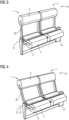
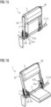
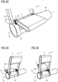
- FIGS. 1 to 3 show a first exemplary embodiment of a folding seat system 10 with two folding seats 1.
- Each folding seat 1 comprises a seat element 2 and a backrest 3.
- the seat element 2 and the backrest 3 in particular each comprise upholstered sections that enable comfortable sitting or leaning against.
- the backrest 3 has an upholstered section
- the seat element 2 has two upholstered sections.
- the backrests 3 each comprise two elongated arms 30.
- the folding seat system 10 includes a lateral fastening element 41 with which the folding seat system 10 can be fastened, for example, to a wall, in particular to a wall of a rail vehicle.
- a foot element 4 of the folding seat system 10 serves as a footrest for one person and/or as additional static support when attached to a wall at the side.
- the folding seats 1 are each set up for leaning against a standing person.
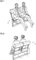
- a person can lean on both sides of each folding seat 1, as is the case, for example, in FIG figure 6 is shown.
- the seat elements 2 are each in a folded or folded-up, third position in which the seat element 2 and the backrest 3 of a folding seat 1 run in a common, vertical plane and thus form a leaning surface.
- a front view of the leaning surfaces is shown.
- FIG 3 is the folding seat system 10 of Figures 1 and 2 shown, in which the seat elements 2 are each in an unfolded, first position.
- the seat elements 2 were pivoted from the third position into the first position.
- the axis of rotation 21 of the seat elements 2 is shown as a dashed line and runs through a section of the seat element 2.
- the seat elements 2 were each pivoted by approximately 90°, for example.
- the folding seats 1 serve to seat a person, as is also the case, for example, in figure 7 is shown.
- the backrests 3 are set up immovably.
- the backrests 3 are consistently in an upright, third position, regardless of the position of the seat elements 2.
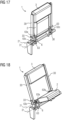
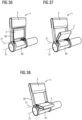
- FIG. 4 to 10 a second exemplary embodiment of the folding seat system 10 is shown, in which the folding seats 1 each have pivotable backrests 3 .
- the backrests 3 are each in a first position, which corresponds to the first position of the seat elements 2 .
- the backrests 3 are folded out in the opposite direction to the seat elements 2 .
- the backrests 3 are each pivoted through an angle of approximately 17° with respect to the upright, third position. This increases comfort when sitting.
- the axes of rotation 31 of the backrests 3 and the axes of rotation 21 of the seat elements 2 coincide.
- FIG 5 is the folding seat system 10 of figure 4 shown, with the seat elements 2 folded up again in their third position.
- the backrests 3, on the other hand, are still in their unfolded, first position.
- the backrests 3 and the seat elements 2 can be pivoted independently of one another.
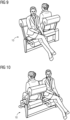
- the exemplary embodiment of the folding seat system 10 is shown, in which the seat elements 2 are each in a second position. In this second position, the seat elements 2 are pivoted in an opposite direction than in the first position. With regard to the third position, the seat elements 2 are in turn pivoted by approximately 90°, for example.
- the backrests 3 are also in a corresponding second position, in which the backrests 3 are pivoted in a direction opposite to the first position. Here, too, the backrests 3 are pivoted by approximately 17°, for example.
- the folding seats 1 can so from opposite directions can be used either for standing leaning or for sitting.
- the second exemplary embodiment of the folding seat system 10 is shown, in which the folding seats 1 are used from different directions.
- both the seat element 2 and the backrest 1 are in their respective first position.
- the seat element 2 and the backrest 3 are in their respective second position.
- the people sitting on the folding seats 1 look in opposite directions, for example once in and once against a direction of travel.
- FIG 11 an exemplary embodiment of a rail vehicle 100 is shown.
- the rail vehicle 100 is, for example, a wagon of a passenger train.
- a large number of the folding seats 1, as they were/are described, for example, in connection with the previous and the following exemplary embodiments, are permanently installed.
- the folding seats 1 are mounted in the rail vehicle 1 via the fastening elements 41 or via a cantilever.
- Figure 11 it can be seen that in the case of two folding seats 1, the seat elements 2 are folded out, one in the direction of travel and one in the opposite direction, and in the case of two further folding seats 1 the seat elements 2 are in the folded, third position in which the folding seats 1 are set up for leaning against a standing person.
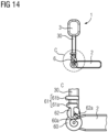
- FIG. 12 to 16 Another exemplary embodiment of the folding seat 1 is shown, in which the seat element 2 and the backrest 3 are coupled to one another via a special transmission 6 .
- the pivoting movements of the seat element 2 and the backrest 3 are no longer independent of one another, but are coupled to one another by the gear mechanism 6 .
- the backrest 3 and the seat element 2 are each in their third position.
- the backrest 3 is thus set upright and the seat element 2 is folded up or folded in.
- a passenger can now lean against the folding seat 1 from both sides while standing.
- the gear 6 comprises a crank wheel 60 from which a pin 60a protrudes.
- the crank wheel 60 is rigidly connected to the seat element 2, so that the crank wheel 60 is rotated when the seat element 2 is pivoted.
- the transmission 6 includes a slotted wheel 62 with an elongated slot 62a. In the third position of the seat member 2 and the backrest 3, the pin 60a engages the slot 62a, whereby the crank wheel 60 and the slotted wheel 62 are mechanically coupled to each other.
- the slotted wheel 62 is in turn coupled to a locking device 61 .
- the locking device 61 comprises a first rack 61a and a second rack 61b.
- the second rack 61b is rigidly connected to the backrest 3, whereas the first rack 61a is connected to the slotted wheel 62 via a push rod and a pivot.
- the two toothed racks 61a, 61b mesh. This blocks the backrest 3 from pivoting.
- a pivoting of the backrest 3 would require a horizontal or circular displacement of the second rack 61b relative to the first rack 61a, which is not possible due to the meshing of the two racks 61a, 61b.
- the seat element 2 is pivoted out of its third position by a predetermined pivoting angle, which is 25° here, for example.
- the backrest 3 is still in its third position.
- the crank wheel 60 has turned with the pin 60a.
- the pin 60a has always remained within the slot 62a and has thereby transmitted a force or torque to the slotted wheel 62, whereby the slotted wheel 62 was rotated simultaneously with the crank wheel 60.
- the first toothed rack 61a was pushed apart in the vertical direction with respect to the second toothed rack 61b via the rotary joint and the push rod.
- the seat element 2 and the backrest 3 are coupled via the transmission 6 in such a way that the backrest 3 can only be pivoted when the seat element 2 is pivoted out of the third position by at least the predetermined pivoting angle.
- the folding seat 1 is shown after the seat element 2 has been fully unfolded into its first position. Up to this point, the pin 60a has continued to engage in the slot 62a and the slotted wheel 62 has been rotated at the same time as the crank wheel 60. As a result, the vertical distance between the two toothed racks 61a, 61b has increased further.
- FIGs 15 and 16 is the embodiment of the folding seat 1 from the Figures 12 to 14 shown in a perspective view.
- the seat element 2 and the backrest 3 in their respective third position. Pivoting of the backrest 3 has not yet been released here.
- the seat element 2 is unfolded into its first position. This also allowed the backrest 3 to pivot.
- the backrest 3 is pivoted into the corresponding first position.
- the axis of rotation 21 of the seat element 2 and the axis of rotation 31 of the backrest 3 coincide.
- the folding seat 1 includes a return spring 7 .
- the return spring 7 is attached to the arm 30 of the backrest 3 at one end.
- the return spring 7 ensures that a lever force acts on the arm 30 which intends to pivot the backrest 3 back into the third position.
- the backrest 3 is pivoted into the first position only if, for example, a person sitting on the seat element 2 leans against the backrest 3 .
- the return spring 7 ensures that the backrest 3 returns to the third position.
- a return to the third position could also be achieved by means of two spiral springs which are aligned in opposite directions and are arranged at the pivot points of the two arms 30 .
- the folding seat 1 is shown in a perspective view.
- the backrest 3 and the seat element 2 are coupled to each other via a gear 6 with respect to their respective pivoting movement.
- the gear mechanism 6, unlike in the previous exemplary embodiment is not designed in such a way that the pivoting of the seat element 2 enables the backrest 3 to pivot independently.
- the transmission 6 is designed here in such a way that the backrest 3 is automatically pivoted along with the pivoting of the seat element 2 and vice versa.
- the transmission 6 in the present case comprises a crank 63 which is rigidly connected to the seat element 2, ie without a movable joint. As a result, when the seat element 2 is pivoted, the crank 63 is also rotated.
- the crank 63 is attached to the seat element 2 with a first end 63a.
- a second end 63b of the crank 63 is attached to the arm 30 of the backrest 3 via a guide element 63c.
- the arm 30 extends perpendicular to the axis of rotation 31 of the backrest 3 and is mounted as part of the backrest 3 so that it can rotate about the axis of rotation 31 .
- the guide member 63c is slidably attached to the arm 30 along a longitudinal axis of the arm 30 .
- the guide element 63c is designed as a clamp which encompasses the arm 30 and is thus mounted on the arm 30 in a displaceable manner.
- the guide element 63c is connected to the second end 63b of the crank 63 via a pivot joint.
- a stop 33 in the form of a projection is formed on the arm 30 .
- the backrest 3 and the seat element 2 are each in their third position, in which the folding seat 1 is used for leaning against a standing person.
- the guide element 63c is arranged along the longitudinal axis 30 at a distance from the stop 33 and at a distance from the axis of rotation 31 .
- the seat element 2 is pivoted out of the third position about its axis of rotation 21 .
- the crank 63 has rotated.
- the second end 63b of the crank 63 was thereby forced to rotate.
- the guide element 63c had to move along the longitudinal axis of the arm 30 in the direction of the stop 33.
- the guide element 63c had to exert a lever force on the arm 30 , which forced the arm 30 or the backrest 3 to pivot in the opposite direction to the pivoting direction of the seat element 2 .
- the backrest 3 was thereby pivoted about its axis of rotation 31 , which in the present case is offset from the axis of rotation 21 of the seat element 2 .
- the transmission ratio is selected in such a way that the pivoting angle of the backrest 3 is smaller than the pivoting angle of the seat element 2. Of course, the transmission also works the other way around when the backrest 3 is pivoted.
- FIG 20 is an embodiment of the folding seat system 10 with two folding seats 1, as shown in FIGS Figures 17 to 19 described shown.
- the gear mechanism 6 as described above.
- the guide element 63c rests against the stop 33 both in the first position and in the second position, so that a pivoting movement beyond the first and second position is not possible.
- the gear also works the other way round when the backrest 3 is pivoted.
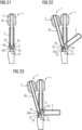
- FIG. 21 to 23 another embodiment of the folding seat 1 is shown.
- the seat element 2 and the backrest 3 are again coupled via a gear 6, so that a pivoting movement of the seat element 2 automatically leads to a pivoting movement of the backrest 3 and vice versa.
- the axes of rotation 21, 31 are offset from one another.
- the transmission 6 includes a crank wheel 60 which is rigidly connected to the seat element 2 .
- the crank wheel 60 is connected to the arm 30 via a guide element 60a in the form of a pin.
- the pin 60a is rigidly attached to the crank wheel 60.
- a main extension direction of the slot 32 runs parallel to the longitudinal axis of the arm 30.
- the seat element 2 is pivoted at an angle to the right.
- the crank wheel 60 has rotated accordingly. This forced the pin 60a into a circular path, sliding it along the slot 32, and at the same time a leverage force was exerted on the arm 30, which forced the arm 30 and the backrest 3 to pivot to the left.
- FIG 24 is a folding seat system 10 with two folding seats 1 as in connection with Figures 21 to 23 described shown. It can be seen that with the gear mechanism 6 just described, it is possible to fold out the seat elements 2 both into the first and into the second position, with the backrests 3 being automatically pivoted as well. In both pivoting directions, the upper end of the slot 32 forms a stop 33 for the pin 60a.
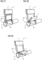
- FIG. 25 to 33 another exemplary embodiment of a folding seat 1 is shown in different positions and in different views.
- the folding seat 1 comprises a cantilever tube 40 which can be attached to a wall so that the folding seat 1 hangs freely above the floor.
- the folding seat 1 does not have any additional support on the floor, but is stably mounted solely by the lateral attachment via the cantilever tube 40 and can carry one or more seated persons.
- FIGs 25 to 29 shows how the seat element 2, starting from the unfolded, second position, is initially transferred to the third position (see figure 27 ), In which the folding seat 1 is set up in particular for leaning against a standing person. Starting from the third position of figure 27 the seat element 2 is then folded out into the first position (see figure 29 ). When the seat element 2 is pivoted, the backrest 3 is automatically pivoted as well. A gear is used again for this purpose.
- the axes of rotation 21, 31 of the seat element 2 and the backrest 3 are spaced apart. The distance remains when the seat element 2 is pivoted from the second position into the first position and the relative position of the axis of rotation 31 of the backrest 3 to the axis of rotation 21 of the seat element 2 is constant. Also with respect to the cantilever tube 40, the positions of the two axes of rotation 21, 31 do not change during pivoting.
- FIGS 30 to 33 are detailed views of the folding seat 1 of Figures 25 to 29 shown, which are intended to illustrate the gear 6 used.
- the transmission 6 has a first gear 64 and a second gear 65 .
- the first gear wheel 64 is rigidly connected to the seat element 2 and is mounted on the cantilever tube via an elongate axle bearing, so that when the seat element 2 is pivoted about its axis of rotation 21, the first gear wheel 64 is also rotated.
- the second gear wheel 65 is rigidly connected to the backrest 3 or to an arm 30 of the backrest 3 (see also figure 31 ). When the backrest 3 is pivoted, the second gear wheel 65 is also rotated (see also figure 31 ).
- the second gear wheel 65 is formed by a ring 34 which runs around the cantilever tube 40 .
- the teeth of the second gear wheel 65 are located on an outside of the ring 34.
- the ring 34 is rotatably mounted with respect to the cantilever tube 40.
- the backrest 3 is pivotable, with the axis of rotation 31 of the backrest 3 running concentrically through the ring 34 or through the cantilever tube 40 .
- the ring 34 includes a groove 34a, the ends of which form stops.
- a bolt (not shown) attached to cantilever tube 40 engages groove 34a. The maximum pivoting angle of the backrest 3 is predetermined by the bolt hitting the ends of the groove 34a.
- the teeth of the second gear wheel 65 do not completely surround the ring 34, but only use a circular segment of the ring 34 with a segment angle of less than 90°.
- FIG 32 shows how the seat element 2 is coupled to the backrest 3 by the first gear wheel 64 being placed on the second gear wheel 65 so that the teeth of the two gear wheels 64, 65 mesh.
- Mechanical stability is achieved in that the seat element 2 is pivotably mounted in an axle bearing of the cantilever tube 40 .
- the first gear wheel 64 is set in rotation, which causes the second gear wheel 65 to rotate. This in turn results in a pivoting of the backrest 3.
- the transmission ratio of the two gears 64, 65 is preferably chosen so that the backrest 3 is pivoted less than the seat element 2.
- the cantilever tube 40 includes two stops 40a, on which the seat element 2 in rests in the first and second position (see Figure 33 ).
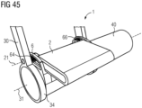
- FIG. 34 to 45 yet another embodiment of the folding seat 1 is shown.
- the seat element 2 is first pivoted into the third position (see figure 36 ) and then starting from the third position to the first position (see figure 38 ) is panned.
- the backrest 3 is pivoted from the second position through the third position to the first position.
- the position of the axis of rotation 21 of the seat element 2 changes here, whereas the position of the axis of rotation 31 of the backrest 3 remains fixed.
- the distance between the axes of rotation 21, 31 remains the same.
- the gear 6 comprises a first gear wheel 64 which is rigidly connected to the seat element 2 and is thus rotated when the seat element 2 is pivoted (see FIG figure 40 ).
- the seat element 2 is rotatably mounted in the arm 30 associated with the backrest 3 via a swivel joint.
- a bolt 64a of the seat element 2 is inserted into a recess of the arm 30 (see FIG Figures 39 , 41, 42 ).
- the bolt 64a engages in an opening 35 in the arm 30 at a distance from the axis of rotation 31 of the backrest 3, so that a lever force can be transmitted to the arm 30 via the bolt 64a.
- the bolt 64a simultaneously forms a bearing for the rotation of the seat element 2.
- the axis of rotation 21 therefore runs through the bolt 64a.
- the arm 30 is again rotatably attached to the cantilever tube 40 via rings 34 (see Fig figure 39 ).
- a toothed rack 66 in the form of a circular arc is arranged on the cantilever tube 40 .
- the rack 66 is fixedly positioned on the cantilever tube 40 .
- the toothed rack 66 is realized by a partly internally toothed gear wheel.
- the transmission also works accordingly when the backrest 3 is pivoted. This might even be the preferred use case.
- the bolt 64a including the coupled gearwheel 64 is displaced, which leads to a movement of the first gearwheel 64 along the toothed rack 66.
- the first gear 64 is rotated together with the pin 64a, resulting in the seat member 2 pivoting.
Description
Die Erfindung bezieht sich auf einen Klappsitz für ein Schienenfahrzeug, umfassend eine Rückenlehne, ein Sitzelement, wobei das Sitzelement zwischen zwei Positionen reversibel hin und her schwenkbar eingerichtet ist,in einer ersten und zweiten Position des Sitzelements das Sitzelement jeweils ausgeklappt ist, sodass der Klappsitz zum Sitzen einer Person auf dem Sitzelement eingerichtet ist, sowie auf ein Klappsitzsystem und ein Schienenfahrzeug.The invention relates to a folding seat for a rail vehicle, comprising a backrest, a seat element, the seat element being set up to be reversibly pivotable back and forth between two positions, in a first and second position of the seat element the seat element is folded out so that the folding seat can Sitting a person is set up on the seat element, as well as a folding seat system and a rail vehicle.
Ein Klappsitz der eingangs genannten Art ist aus der
Eine zu lösende Aufgabe besteht darin, einen Klappsitz für ein Schienenfahrzeug anzugeben, der an ein variierendes Personenaufkommen angepasst werden kann. Eine weitere zu lösende Aufgabe besteht darin, ein Klappsitzsystem mit einem solchen Klappsitz anzugeben. Noch eine zu lösende Aufgabe besteht darin, ein Schienenfahrzeug mit einem solchen Klappsitz anzugeben.One problem to be solved is to specify a folding seat for a rail vehicle that can be adapted to a varying number of people. Another problem to be solved is to specify a folding seat system with such a folding seat. Another problem to be solved is to specify a rail vehicle with such a folding seat.
Diese Aufgabe wird erfindungsgemäß durch die Merkmale des Anspruchs 1 gelöst, während vorteilhafte Ausgestaltungen und Weiterbildungen der Erfindung den Unteransprüchen entnommen werden können.This object is achieved according to the invention by the features of
Gemäß zumindest einer Ausführungsform umfasst der Klappsitz eine Rückenlehne und ein Sitzelement. Das Sitzelement ist zwischen drei Positionen reversibel hin und her schwenkbar eingerichtet. In einer ersten und zweiten Position des Sitzelements ist das Sitzelement jeweils ausgeklappt, sodass der Klappsitz zum Sitzen einer Person auf dem Sitzelement eingerichtet ist. In einer dritten Position des Sitzelements ist das Sitzelement eingeklappt und bildet zusammen mit der Rückenlehne eine Anlehnfläche zum Anlehnen einer stehenden Person. Bezüglich der dritten Position ist das Sitzelement in seiner ersten und zweiten Position in einander entgegengesetzte Richtungen geschwenkt.According to at least one embodiment, the folding seat includes a backrest and a seat element. The seat element is set up to be reversibly pivotable back and forth between three positions. In a first and second position of the seat element the seat element is unfolded in each case, so that the folding seat is set up for a person to sit on the seat element. In a third position of the seat element, the seat element is folded in and, together with the backrest, forms a leaning surface for leaning on a standing person. With respect to the third position, the seat member is pivoted in opposite directions in its first and second positions.
Die dritte Position des Sitzelements ist also eine Zwischenposition zwischen der ersten und zweiten Position. Ausgehend von der dritten Position kann das Sitzelement durch Schwenken in eine Richtung in seine erste Position und durch Schwenken in die entgegengesetzte Richtung in die zweite Position überführt werden. Der Klappsitz ist insbesondere so eingerichtet, dass das Sitzelement manuell durch eine Person zwischen den drei Positionen geschwenkt werden kann. Das Schwenken wird bevorzugt nicht elektronisch unterstützt, sondern erfolgt rein manuell. Zwischen den drei Positionen ist das Sitzelement bevorzugt stufenlos schwenkbar.The third position of the seat element is therefore an intermediate position between the first and second position. Starting from the third position, the seat element can be transferred to its first position by pivoting in one direction and to the second position by pivoting in the opposite direction. In particular, the folding seat is set up in such a way that the seat element can be pivoted manually by one person between the three positions. The pivoting is preferably not supported electronically, but takes place purely manually. The seat element can preferably be continuously pivoted between the three positions.
Das Sitzelement umfasst zum Beispiel zwei einander gegenüberliegende Sitzflächen. Ebenso umfasst die Rückenlehne bevorzugt zwei einander gegenüberliegende Flächen. Bei korrekter Verwendung oder Ausrichtung des Klappsitzes zeigt in der ersten Position des Sitzelements die erste Sitzfläche nach oben, sodass sich eine Person auf die erste Sitzfläche setzen kann und an der ersten Fläche der Rückenlehne anlehnen kann. In der zweiten Position des Sitzelements zeigt die zweite Sitzfläche nach oben, sodass sich eine Person auf die zweite Sitzfläche setzen kann und an der zweiten Fläche der Rückenlehne anlehnen kann. Beispielsweise ist im eingebauten Zustand des Klappsitzes das Sitzelement in der ersten Position in Fahrtrichtung ausgeklappt und in der zweiten Position entgegen der Fahrtrichtung ausgeklappt.The seating element comprises, for example, two seating surfaces lying opposite one another. Likewise, the backrest preferably comprises two opposing surfaces. When the folding seat is used or aligned correctly, the first seat surface faces upwards in the first position of the seat element, so that a person can sit on the first seat surface and lean against the first surface of the backrest. In the second position of the seat element, the second seating surface faces upwards, so that a person can sit down on the second seating surface and lean against the second surface of the backrest. For example, when the folding seat is installed, the seat element is in the first position unfolded in the direction of travel and unfolded in the second position against the direction of travel.
In der dritten Position des Sitzelements ist das Sitzelement eingeklappt. Der Klappsitz dient dann nicht zum Sitzen einer Person, sondern zum beidseitigen Anlehnen einer stehenden Person. Insbesondere bilden dann die zweite Sitzfläche und die erste Fläche der Rückenlehne eine erste Anlehnfläche zum Anlehnen einer stehenden Person. Die erste Sitzfläche und die zweite Fläche der Rückenlehne bilden eine der ersten Anlehnfläche gegenüberliegende zweite Anlehnfläche zum Anlehnen einer weiteren stehenden Person. In der dritten Position des Sitzelements können sich also Personen von zwei einander gegenüberliegenden Seiten gleichzeitig an den Klappsitz anlehnen.In the third position of the seat element, the seat element is folded in. The folding seat is then not used for sitting a person, but for leaning on both sides of a standing person. In particular, the second seat surface and the first surface of the backrest then form a first leaning surface for leaning on a standing person. The first seat surface and the second surface of the backrest form a second leaning surface opposite the first leaning surface for leaning against another standing person. In the third position of the seat element, people can lean against the folding seat from two opposite sides at the same time.
In der dritten Position des Sitzelements erstrecken sich beispielsweise das Sitzelement und die Rückenlehne entlang einer gemeinsamen Ebene, wobei bei korrekter Verwendung oder Ausrichtung des Klappsitzes die gemeinsame Ebene vertikal verläuft. In der ersten und zweiten Position erstreckt sich das Sitzelement beispielsweise entlang einer Ebene, die quer, insbesondere senkrecht, zu einer Haupterstreckungsebene der Rückenlehne verläuft.In the third position of the seat element, for example, the seat element and the backrest extend along a common plane, with the common plane running vertically when the folding seat is used or aligned correctly. In the first and second position, the seat element extends, for example, along a plane that runs transversely, in particular perpendicularly, to a main plane of extension of the backrest.
Im eingebauten Zustand des Klappsitzes verläuft eine Drehachse des Sitzelements bevorzugt horizontal und besonders bevorzugt quer zur Fahrzeuglängsachse. Die Drehachse des Sitzelements ist die Achse, bezüglich der das Sitzelement beim Schwenken eine reine Rotationsbewegung ausführt. Das Sitzelement ist um die Drehachse drehbar gelagert.In the installed state of the folding seat, an axis of rotation of the seat element preferably runs horizontally and particularly preferably transversely to the longitudinal axis of the vehicle. The axis of rotation of the seat element is the axis with respect to which the seat element executes a pure rotational movement when pivoting. The seat element is rotatably mounted about the axis of rotation.
Der hier beschriebenen Erfindung liegt insbesondere die Erkenntnis zu Grunde, dass in Schienenfahrzeugen, insbesondere in Nahverkehrszügen, wie U- oder S-Bahnen, das Personenaufkommen stark variieren kann. Beispielsweise herrscht in Stadtzentren ein hohes Personenaufkommen, wohingegen in Vororten weniger Personen in dem Schienenfahrzeug sind oder in den Stationen zusteigen. Der beschriebene Klappsitz erlaubt eine Nutzung, die an das Personenaufkommen angepasst ist. Bei hohem Personenaufkommen ist die dritte Position des Sitzelements besonders platzsparend und erlaubt das Anlehnen von stehenden Person von zwei einander gegenüberliegenden Seiten. Zudem bewirkt der Klappsitz mit dem Sitzelement in der dritten Position eine Sortierfunktion innerhalb eines Waggons durch entsprechende Zonierung. Nimmt das Personenaufkommen ab, so kann der Klappsitz zum Sitzen einer Person genutzt werden und bietet entsprechend mehr Komfort. Da das Sitzelement in einander gegenüberliegende Richtungen ausschwenkbar oder ausklappbar ist, kann auch dann noch der Platz in dem Schienenfahrzeug optimal genutzt werden. Der Klappsitz kann beidseitig genutzt werden und lässt sich zum Beispiel gezielt in oder gegen die Fahrtrichtung des Zuges ausrichten.The invention described here is based in particular on the knowledge that in rail vehicles, in particular in local trains, such as underground or suburban trains, the number of passengers can vary greatly. For example, in city centers there is a high volume of people, whereas in suburbs there are fewer people in the rail vehicle or boarding in the stations. The folding seat described allows use that is adapted to the number of people. When there is a large number of people, the third position of the seat element is particularly space-saving and allows a person standing to lean against it from two opposite sides. In addition, the folding seat with the seat element in the third position has a sorting function within a wagon through appropriate zoning. If the number of people decreases, the folding seat can be used to sit one person and offers more comfort accordingly. Since the seat element can be pivoted or folded out in opposite directions, the space in the rail vehicle can still be optimally used. The folding seat can be used on both sides and can, for example, be aligned in or against the direction of travel of the train.
Gemäß zumindest einer Ausführungsform ist die Schwenkbarkeit des Sitzelements elektronisch ein- und ausschaltbar. Bevorzugt ist die Schwenkbarkeit des Klappsitzes durch einen Zugführer elektronisch freigebar. Beispielsweise umfasst der Klappsitz ein Verriegelungssystem, das elektronisch steuerbar ist. Das Verriegelungssystem ist zwischen einem geöffneten und einen geschlossenen Zustand hin und her schaltbar. Im geschlossenen Zustand ist das Verriegelungssystem dazu eingerichtet, den Klappsitz in der dritten Position des Sitzelements zu verriegeln. Ein manuelles Schwenken des Sitzelements in die erste und zweite Position durch eine Person ist dann nicht möglich. Durch Umschalten in den geöffneten Zustand, beispielswiese wenn das Personenaufkommen in dem Schienenfahrzeug entsprechend niedrig ist, wird das Schwenken in die erste und zweite Position freigegeben.According to at least one embodiment, the pivotability of the seat element can be switched on and off electronically. The pivotability of the folding seat can preferably be released electronically by a train driver. For example, the folding seat includes a locking system that is electronically controllable. The locking system is switchable between an open and a closed state. In the closed state, the locking system is set up to lock the folding seat in the third position of the seat element. It is then not possible for a person to manually pivot the seat element into the first and second position. By switching to the open state, for example when the number of people in the rail vehicle is correspondingly low, pivoting to the first and second positions is released.
Gemäß zumindest einer Ausführungsform umfasst der Klappsitz eine Arretiervorrichtung zum Arretieren oder Sicheren des Sitzelements in der ersten und/oder zweiten und/oder dritten Position. Die Arretiervorrichtung blockiert die Schwenkbarkeit des Sitzelements. Beispielsweise blockiert die Arretiervorrichtung die Schwenkbarkeit automatisch, sobald das Sitzelement in die erste und/oder zweite und/oder dritte Position geschwenkt ist. Die Arretiervorrichtung ist von einer Person beispielsweise manuell lösbar, wodurch ein Schwenken aus der ersten oder zweiten oder dritten Position freigegeben wird. Dazu ist an dem Klappsitz beispielsweise ein Druckknopf oder ein Hebel vorgesehen, der von einem Fahrgast betätigt werden kann. Die Arretiervorrichtung ist derart mit dem Hebel oder Knopf gekoppelt, dass durch Ziehen des Hebels oder Drücken des Knopfes die Arretiervorrichtung gelöst wird und die Schwenkbarkeit des Sitzelements freigegeben wird.According to at least one embodiment, the folding seat includes a locking device for locking or securing the seat element in the first and/or second and/or third position. The locking device blocks the pivoting of the seat element. For example, the locking device blocks the ability to pivot automatically as soon as the seat element is pivoted into the first and/or second and/or third position. The locking device can be released manually by a person, for example, so that pivoting out of the first or second or third position is released. For this purpose, for example, a push button or a lever is provided on the folding seat, which can be actuated by a passenger. The locking device is coupled to the lever or button in such a way that pulling the lever or pressing the button releases the locking device and allows the seat element to pivot.
Bevorzugt ist die Arretiervorrichtung freigebar, zum Beispiel elektronisch durch den Zugführer. Erst wenn die Arretiervorrichtung freigegeben ist, kann eine Person sie manuell lösen.The locking device can preferably be released, for example electronically by the train driver. Only when the locking device is released can a person release it manually.
Gemäß zumindest einer Ausführungsform ist die Rückenlehne zwischen drei Positionen reversibel hin und her schwenkbar. Die Rückenlehne ist bevorzugt stufenlos zwischen den drei Positionen hin und her schwenkbar. Die Drehachse der Rückenlehne, um die die Rückenlehne beim Schwenken rotiert wird, verläuft im eingebauten Zustand des Klappsitzes bevorzugt ebenfalls horizontal, ganz besonders bevorzugt parallel zur Drehachse des Sitzelements. In der dritten Position ist die Rückenlehne bevorzugt hochgestellt beziehungsweise vertikal ausgerichtet. In der ersten und zweiten Position ist die Rückenlehne bezüglich der dritten Position insbesondere in entgegengesetzte Richtungen geschwenkt.According to at least one embodiment, the backrest can be reversibly pivoted back and forth between three positions. The backrest can preferably be continuously pivoted back and forth between the three positions. The axis of rotation of the backrest, about which the backrest is rotated during pivoting, preferably also runs horizontally when the folding seat is installed, very particularly preferably parallel to the axis of rotation of the seat element. In the third position, the backrest is preferably raised or vertical aligned. In the first and second position, the backrest is pivoted in particular in opposite directions with respect to the third position.
Wie das Sitzelement kann auch die Rückenlehne durch das Verriegelungssystem und/oder die Arretiervorrichtung gesichert beziehungsweise fixiert werden. Durch Öffnen des Verriegelungssystems oder durch Lösen der Arretiervorrichtung kann das Schwenken der Rückenlehne freigegeben werden. Ein versehentliches Schwenken der Rückenlehen durch eine sich anlehnende Person kann so vermieden werden.Like the seat element, the backrest can also be secured or fixed by the locking system and/or the locking device. The backrest can be swiveled by opening the locking system or releasing the locking device. Accidental swiveling of the backrest by a person leaning against it can thus be avoided.
Gemäß zumindest einer Ausführungsform korrespondieren die drei Positionen der Rückenlehne mit den drei Positionen des Sitzelements. Das heißt, die erste Position des Sitzelements ist der ersten Position der Rückenlehne zugeordnet, die zweite Position des Sitzelements ist der zweiten Position der Rückenlehne zugeordnet und die dritte Position des Sitzelements ist der dritten Position der Rückenlehne zugeordnet. Beispielsweise ist der Klappsitz so eingerichtet, dass, sobald das Sitzelement sich in einer seiner drei Positionen befindet, sich die Rückenlehne automatisch in der korrespondierenden Position befindet. Die Rückenlehne und das Sitzelement sind in ihren jeweiligen ersten und zweiten Positionen bevorzugt in einander entgegengesetzte Richtungen geschwenkt.According to at least one embodiment, the three positions of the backrest correspond to the three positions of the seat element. That is, the first position of the seat element is associated with the first position of the backrest, the second position of the seat element is associated with the second position of the backrest, and the third position of the seat element is associated with the third position of the backrest. For example, the folding seat is set up so that as soon as the seat element is in one of its three positions, the backrest is automatically in the corresponding position. The backrest and seat member are preferably pivoted in opposite directions in their respective first and second positions.
Gemäß zumindest einer Ausführungsform umfasst der Klappsitz ein Rückstellsystem zur Rückstellung der Rückenlehne und/oder des Sitzelements in die dritte Position. Das Rückstellsystem kann automatisch zur Rückstellung der Rückenlehen und/oder des Sitzelements führen, sobald eine Person von dem Sitzelement aufsteht. Bevorzugt ist das Rückstellsystem elektronisch ansteuerbar, zum Beispiel von einem Zugführer, sodass durch elektronische Ansteuerung eine Rückstellung der Rückenlehne und/oder des Stilelements automatisch erfolgt. Das Rückstellsystem umfasst zum Beispiel ein Zug- oder Druckfeder- oder Spiralfedersystem oder einen Motor oder einen Magneten.According to at least one embodiment, the folding seat includes a return system for returning the backrest and/or the seat element to the third position. The reset system can automatically reset the backrests and/or the seat element as soon as a person stands up from the seat element. Preferably, the reset system is electronically controlled, for example by a train driver, so that by electronic control, the backrest and/or the style element are automatically reset. The restoring system includes, for example, a tension or compression spring or spiral spring system or a motor or a magnet.
Gemäß zumindest einer Ausführungsform sind die Rückenlehne und das Sitzelement unabhängig voneinander zwischen den jeweiligen drei Positionen hin und her schwenkbar. Das heißt, in jeder Position des Sitzelements kann die Rückenlehne frei geschwenkt werden und umgekehrt.According to at least one embodiment, the backrest and the seat element can be pivoted back and forth between the respective three positions independently of one another. This means that the backrest can be swiveled freely in any position of the seat element and vice versa.
Gemäß zumindest einer Ausführungsform sind die Rückenlehne und das Sitzelement hinsichtlich der jeweiligen Schwenkbewegungen über ein Getriebe, insbesondere über ein Koppelgetriebe, gekoppelt, sodass durch Schwenken der Rückenlehne oder des Sitzelements heraus aus einer der drei jeweiligen Positionen das Schwenken des Sitzelements oder der Rückenlehne erzwungen oder freigegeben wird.According to at least one embodiment, the backrest and the seat element are coupled with regard to the respective pivoting movements via a gear, in particular via a linkage, so that pivoting the backrest or the seat element out of one of the three respective positions forces or releases the pivoting of the seat element or the backrest becomes.
Insbesondere ist das Getriebe so eingerichtet, dass, sobald das Sitzelement in einer seiner drei Positionen ist, die Rückenlehne automatisch in der korrespondierenden Position ist. Beim Schwenken des Sitzelements oder der Rückenlehne heraus aus dessen/ihrer Position wird die Rückenlehne beziehungsweise das Sitzelement dann automatisch heraus aus ihrer/dessen Position geschwenkt. Bevorzugt werden die Rückenlehne und das Sitzelement dann in einander entgegengesetzte Richtungen geschwenkt. Zum Beispiel wird dann weiter durch Schwenken des Sitzelements oder der Rückenlehne in eine weitere Position die Rückenlehne beziehungsweise das Sitzelement automatisch in die korrespondierende Position geschwenkt. Das Getriebe ist bevorzugt symmetrisch, sodass es beim Schwenken des Sitzelements/der Rückenlehne in beide Richtungen gleichermaßen funktioniert.In particular, the gearing is set up in such a way that as soon as the seat element is in one of its three positions, the backrest is automatically in the corresponding position. When the seat element or the backrest is pivoted out of its position, the backrest or the seat element is then automatically pivoted out of its position. The backrest and the seat element are then preferably pivoted in mutually opposite directions. For example, by pivoting the seat element or the backrest into a further position, the backrest or the seat element is then automatically pivoted into the corresponding position. The transmission is preferably symmetrical, so that when pivoting the seat element / the Backrest works equally in both directions.
Alternativ wird erst durch Schwenken des Sitzelements, beispielsweise heraus aus dessen dritter Position, ein Schwenken der Rückenlehne freigegeben. Für diesen Fall umfasst das Getriebe zum Beispiel eine Sperrvorrichtung, die ein Schwenken der Rückenlehne blockiert. Das Getriebe ist bevorzugt so eingerichtet, dass durch Schwenken des Sitzelements heraus aus dessen dritter Position um einen vorgegebenen Schwenkwinkel die Sperrvorrichtung gelöst wird und dadurch ein Schwenken der Rückenlehne freigegeben wird.Alternatively, pivoting of the backrest is released only by pivoting the seat element, for example out of its third position. In this case, the gear includes, for example, a locking device that blocks pivoting of the backrest. The gear mechanism is preferably set up in such a way that the locking device is released by pivoting the seat element out of its third position by a predetermined pivoting angle, and pivoting of the backrest is thereby released.
Gemäß zumindest einer Ausführungsform umfasst das Getriebe ein Kurbelelement mit einem Stift, eine Sperrvorrichtung und ein geschlitztes Rad. Das Kurbelelement ist starr, das heißt ohne bewegliches Gelenk, mit dem Sitzelement verbunden, sodass beim Schwenken des Sitzelements das Kurbelelement gedreht wird und dabei der Stift entlang einer Kreislinie oder Kreisbahn bewegt wird. In der dritten Position des Sitzelements ist die Sperrvorrichtung in einem Sperrzustand, wodurch das Schwenken der Rückenlehne blockiert ist. Ferner greift in der dritten Position des Sitzelements der Stift in den Schlitz des geschlitzten Rades ein. Das Getriebe ist so eingerichtet, dass beim Schwenken des Sitzelements aus der dritten Position heraus zumindest bis zu einem vorgegebenen Schwenkwinkel der Stift weiter in den Schlitz eingreift und eine Kraft auf das geschlitzte Rad ausübt, wodurch das geschlitzte Rad gedreht wird. Die Sperrvorrichtung ist mit dem geschlitzten Rad derart gekoppelt, dass durch die beim Überschreiten des vorgegebenen Schwenkwinkels korrespondierende Drehung des geschlitzten Rades der Sperrzustand gelöst wird und das Schwenken der Rückenlehne freigegeben wird.According to at least one embodiment, the transmission comprises a crank element with a pin, a locking device and a slotted wheel. The crank element is rigid, i.e. without a movable joint, connected to the seat element, so that when the seat element is pivoted, the crank element is rotated and the pin along is moved along a circular line or circular path. In the third position of the seat element, the locking device is in a locking state, as a result of which the pivoting of the backrest is blocked. Also, in the third position of the seat member, the pin engages the slot of the slotted wheel. The gearing is arranged such that as the seat member pivots out of the third position at least up to a predetermined pivot angle, the pin continues to engage the slot and applies a force to the slotted wheel, thereby rotating the slotted wheel. The locking device is coupled to the slotted wheel in such a way that the locking state is released by the corresponding rotation of the slotted wheel when the predetermined pivoting angle is exceeded and the pivoting of the backrest is released.
Durch das Drehen des geschlitzten Rades wird insbesondere ein Mechanismus ausgelöst, der, sobald der vorgegebene Schwenkwinkel des Sitzelements überschritten ist, die Sperrvorrichtung löst. Zumindest bis zu dem vorgegebenen Schwenkwinkel sind das Sitzelement und das geschlitzte Rad gekoppelt. Zum Beispiel umfasst die Sperrvorrichtung eine Bremse, die über eine Schubstange mit dem geschlitzten Rad verbunden ist, wobei beim Drehen des geschlitzten Rades die Schubstange linear bewegt wird und dadurch die Bremse löst.The turning of the slotted wheel in particular triggers a mechanism which, as soon as the predetermined pivoting angle of the seat element is exceeded, releases the locking device. The seat element and the slotted wheel are coupled at least up to the predetermined swivel angle. For example, the locking device includes a brake connected to the slotted wheel via a push rod, wherein as the slotted wheel rotates, the push rod is moved linearly, thereby releasing the brake.
Nach dem Lösen der Sperrvorrichtung ist die Rückenlehne bevorzugt unabhängig von dem Sitzelement schwenkbar. Der vorgegebene Schwenkwinkel beträgt beispielsweise zwischen einschließlich 10° und 45°, beispielsweise 25°.After the locking device has been released, the backrest can preferably be pivoted independently of the seat element. The predetermined swivel angle is between 10° and 45° inclusive, for example 25°.
Nach dem Überschreiten des vorgegebenen Schwenkwinkels kann der Stift den Schlitz verlassen, wodurch das Kurbelelement und das geschlitzte Rad entkoppelt werden. Ein weiteres Drehen des Kurbelelements bewirkt dann keine weitere Drehung des geschlitzten Rades. Mit anderen Worten basiert das Getriebe dann auf dem Funktionsprinzip eines Malteserkreuzgetriebes. Dies ist vorteilhaft, denn dadurch kann die Sperrvorrichtung ebenfalls von dem Kurbelelement entkoppelt werden. Ein weiteres Schwenken des Sitzelements auch weit über den vorgegebenen Schwenkwinkel hinaus führt dann beispielsweise nicht dazu, dass die Sperrvorrichtung wieder in den Sperrzustand überführt wird.After the predetermined pivoting angle has been exceeded, the pin can leave the slot, as a result of which the crank element and the slotted wheel are decoupled. Further rotation of the crank member then causes no further rotation of the slotted wheel. In other words, the gear is then based on the functional principle of a geneva gear. This is advantageous because it also allows the locking device to be decoupled from the crank element. A further pivoting of the seat element, even far beyond the predetermined pivoting angle, does not result in the locking device being switched back into the locked state, for example.
Bevorzugt ist das Getriebe so eingerichtet, dass beim Zurückschwenken des Sitzelements und vor dem Unterschreiten des vorgegebenen Schwenkwinkels, der Stift wieder in den Schlitz eingreift, dadurch bei weiterem Zurückschwenken das geschlitzte Rad zurückgedreht wird und dadurch die Sperrvorrichtung wieder in den Sperrzustand überführt wird.The gear mechanism is preferably set up in such a way that when the seat element is pivoted back and before the specified pivoting angle is not reached, the pin engages in the slot again, thereby causing the slotted element to be pivoted back further Wheel is turned back and thereby the locking device is transferred back into the locked state.
Das Kurbelelement kann ein Kurbelrad oder eine Kurbel sein. Die Drehachse des Sitzelements verläuft insbesondere durch den Kreismittelpunkt des Kurbelrads oder durch ein Ende der Kurbel. Der Stift ist insbesondere bezüglich der Drehachse des Sitzelements versetzt an dem Kurbelelement und in einem festen Abstand zur Drehachse des Sitzelements befestigt. Dadurch ist die Bewegung entlang der Kreislinie beim Schwenken des Sitzelements gegeben. Eine Haupterstreckungsrichtung des Stifts verläuft beispielsweise parallel zur Drehachse des Sitzelements.The crank element can be a crank wheel or a crank. The axis of rotation of the seat element runs in particular through the center of the circle of the crank wheel or through one end of the crank. In particular, the pin is attached to the crank element offset with respect to the axis of rotation of the seat element and at a fixed distance from the axis of rotation of the seat element. As a result, the movement along the circular line is given when the seat element is pivoted. A main extension direction of the pin runs, for example, parallel to the axis of rotation of the seat element.
Eine Drehachse des geschlitzten Rads ist insbesondere versetzt zu der Drehachse des Sitzelements, verläuft aber parallel zur Drehachse des Sitzelements. Eine Längsachse des Schlitzes verläuft beispielsweise senkrecht zur Drehachse des Sitzelements. Während der durch den Stift erzwungenen Drehung des geschlitzten Rads bewegt sich der Stift entlang einer Längsachse des Schlitzes.Specifically, an axis of rotation of the slotted wheel is offset from the axis of rotation of the seat member but is parallel to the axis of rotation of the seat member. A longitudinal axis of the slot runs, for example, perpendicularly to the axis of rotation of the seat element. During rotation of the slotted wheel forced by the pin, the pin moves along a longitudinal axis of the slot.
Gemäß zumindest einer Ausführungsform umfasst das Getriebe ein Kurbelelement mit einem an dem Kurbelelement befestigten Führungselement. Das Kurbelelement ist starr, das heißt ohne bewegliches Gelenk, mit dem Sitzelement verbunden, sodass das Kurbelelement beim Schwenken des Sitzelements gedreht wird. Dabei wird das Führungselement entlang einer Kreislinie bewegt. Die Rückenlehne umfasst einen länglichen Arm, der sich quer zur Drehachse der Rückenlehne erstreckt. Das Führungselement ist mit dem Arm verbunden und ist entlang einer Längsachse des Arms verschiebbar an dem Arm befestigt. Das Getriebe ist so eingerichtet, dass beim Schwenken des Sitzelements das Führungselement entlang der Längsachse des Arms verschoben wird und gleichzeitig eine Hebelkraft auf den Arm ausübt, die ein Schwenken der Rückenlehne um dessen Drehachse erzwingt. Es versteht sich von selbst, dass dieses Getriebe auch in umgekehrter Weise funktioniert, also durch Schwenken der Rückenlehne das Führungselement entlang des Arms verschoben wird und dadurch das Kurbelelement gedreht beziehungsweise das Sitzelement geschwenkt wird.According to at least one embodiment, the transmission includes a crank element with a guide element fastened to the crank element. The crank element is rigidly connected to the seat element, that is to say without a movable joint, so that the crank element is rotated when the seat element is pivoted. The guide element is moved along a circular line. The backrest includes an elongate arm that extends transversely to the axis of rotation of the backrest. The guide member is connected to the arm and is slidably mounted to the arm along a longitudinal axis of the arm. The gear is set up so that when pivoting the seat element the guide element is displaced along the longitudinal axis of the arm and at the same time exerts a leverage on the arm, which forces the backrest to pivot about its axis of rotation. It goes without saying that this mechanism also works in the opposite way, ie by pivoting the backrest, the guide element is displaced along the arm and the crank element is thereby rotated or the seat element is pivoted.
Das Kurbelelement kann wiederum eine Kurbel oder ein Kurbelrad sein. Das Führungselement ist bezüglich der Drehachse des Sitzelements versetzt und in einem festen Abstand zu der Drehachse des Sitzelements an dem Kurbelelement befestigt, wodurch das Führungselement beim Schwenken des Sitzelements auf die Kreisbahn gezwungen wird. Der Arm der Rückenlehne ist länglich ausgebildet und bildet einen Hebel. In der dritten Position der Rückenlehne und im bestimmungsgemäß eingebauten Zustand des Klappsitzes verläuft die Längsachse des Arms beispielsweise vertikal. Die Längsachse des Arms verläuft insbesondere senkrecht zu den Drehachsen des Sitzelements und der Rückenlehne.The crank element can in turn be a crank or a crank wheel. The guide member is offset with respect to the axis of rotation of the seat member and is fixed to the crank member at a fixed distance from the axis of rotation of the seat member, thereby urging the guide member to orbit upon pivoting of the seat member. The arm of the backrest is elongated and forms a lever. In the third position of the backrest and when the folding seat is installed as intended, the longitudinal axis of the arm runs vertically, for example. The longitudinal axis of the arm runs, in particular, perpendicular to the axes of rotation of the seat element and the backrest.
Das Führungselement ist in der dritten Position des Sitzelements bevorzugt beabstandet zu der Drehachse der Rückenlehne an dem Arm befestigt. Wird nun eine Kraft auf das Sitzelement ausgeübt, so wird diese Kraft über das Kurbelelement und das Führungselement auf den Arm übertragen. Die Kreisbewegung des Führungselements ist dadurch ermöglicht, dass das Führungselement linear beweglich an dem Arm befestigt ist und die Rückenlehne zusammen mit dem Arm schwenkbar ist. Mit anderen Worten realisiert das Führungselement ein Schubdrehgelenk zwischen dem Arm und dem Kurbelelement.In the third position of the seat element, the guide element is preferably attached to the arm at a distance from the axis of rotation of the backrest. If a force is now exerted on the seat element, this force is transmitted to the arm via the crank element and the guide element. The circular movement of the guide element is made possible in that the guide element is linearly movably attached to the arm and the backrest can be pivoted together with the arm. In other words, the guide element implements a sliding pivot joint between the arm and the crank element.
Gemäß zumindest einer Ausführungsform ist das Führungselement eine Klammer, die den Arm umgreift und über ein Drehgelenk an dem Kurbelelement befestigt ist. Insbesondere ist die Klammer also bezüglich des Kurbelelements drehbar an dem Kurbelelement befestigt. Die Befestigung ist aber dergestalt, dass der Abstand zur Drehachse des Sitzelements unveränderlich ist. Mit anderen Worten hat die bewegliche Verbindung zwischen der Klammer und dem Kurbelelement nur einen Freiheitsgrad, nämlich die Rotation.In accordance with at least one embodiment, the guide element is a clamp which encloses the arm and attaches it via a swivel joint attached to the crank element. In particular, the clamp is thus fastened to the crank element such that it can rotate with respect to the crank element. However, the attachment is such that the distance from the axis of rotation of the seat element is unchangeable. In other words, the movable connection between the clamp and the crank element has only one degree of freedom, namely rotation.
Gemäß zumindest einer Ausführungsform ist das Führungselement ein Stift. Der Arm weist einen länglichen Schlitz auf, der sich entlang der Längsachse des Arms erstreckt. Der Stift greift in den Schlitz ein und ist entlang des Schlitzes verschiebbar gelagert. Der Stift ist beispielsweise starr an dem Kurbelelement befestigt. Eine Längsachse des Stifts verläuft beispielsweise parallel zur Drehachse des Sitzelements.According to at least one embodiment, the guide element is a pin. The arm has an elongated slot that extends along the longitudinal axis of the arm. The pin engages the slot and is slidably mounted along the slot. For example, the pin is rigidly attached to the crank member. A longitudinal axis of the pin runs, for example, parallel to the axis of rotation of the seat element.
Gemäß zumindest einer Ausführungsform weist der Arm zumindest einen Anschlag auf, sodass das Führungselement nur bis zu dem Anschlag entlang der Längsachse des Arms verschiebbar ist. Der Anschlag kann beispielsweise durch einen Vorsprung an dem Arm ausgebildet sein, über den das Führungselement, beispielsweise in Form einer Klammer, nicht verschoben werden kann. Ist das Führungselement beispielsweise als Stift ausgebildet, so kann der Anschlag ein Ende des Schlitzes sein, an dem der Stift anschlägt.According to at least one embodiment, the arm has at least one stop, so that the guide element can only be displaced along the longitudinal axis of the arm as far as the stop. The stop can be formed, for example, by a projection on the arm over which the guide element, for example in the form of a clip, cannot be displaced. If the guide element is designed as a pin, for example, the stop can be an end of the slot on which the pin strikes.
Gemäß zumindest einer Ausführungsform schlägt das Führungselement sowohl in der ersten als auch in der zweiten Position des Sitzelements an einem Anschlag an. Insbesondere ist durch den Anschlag verhindert, dass das Sitzelement über die erste oder zweite Position hinaus weg von der dritten Position schwenkbar ist. Zwischen der ersten und der zweiten Position, beispielsweise in der dritten Position, ist das Führungselement bevorzugt von dem Anschlag beabstandet. In der ersten und zweiten Position kann das Führungselement am selben Anschlag anschlagen.According to at least one embodiment, the guide element abuts against a stop both in the first and in the second position of the seat element. In particular, the stop prevents the seat element from being pivotable beyond the first or second position and away from the third position. Between the first and the second position, for example in the third position, the guide element is preferably spaced apart from the stop. In the first and second position, the guide element can hit the same stop.
Gemäß zumindest einer Ausführungsform umfasst das Getriebe ein erstes Zahnrad und ein zweites Zahnrad. Das erste Zahnrad ist starr mit dem Sitzelement verbunden, sodass das erste Zahnrad beim Schwenken des Sitzelements gedreht wird. Das zweite Zahnrad ist starr mit der Rückenlehne verbunden, sodass das zweite Zahnrad beim Schwenken der Rückenlehne gedreht wird. Das erste Zahnrad und das zweite Zahnrad greifen ineinander, sodass beim Schwenken des Sitzelements ein Schwenken der Rückenlehne erzwungen wird. Auch bei diesem Getriebe versteht sich von selbst, dass es ebenso in umgekehrter Weise funktioniert, also durch Schwenken der Rückenlehne das Schwenken des Sitzelements erzwungen wird.According to at least one embodiment, the transmission includes a first gear wheel and a second gear wheel. The first gear is rigidly connected to the seat member such that the first gear is rotated as the seat member pivots. The second gear wheel is rigidly connected to the backrest, so that the second gear wheel is rotated when the backrest is pivoted. The first gear wheel and the second gear wheel mesh with one another, so that when the seat element is pivoted, the backrest is forced to pivot. It goes without saying that this mechanism also works in the opposite way, that is, by pivoting the backrest, the pivoting of the seat element is forced.
Das Übersetzungsverhältnis der beiden Zahnräder ist vorzugsweise so gewählt, dass die Rückenlehne weniger stark geschwenkt wird als das Sitzelement. Beispielsweise wird beim Schwenken des Sitzelements um 45° die Rückenlehne um höchstens 10° und mindestens 5° geschwenkt.The transmission ratio of the two gears is preferably chosen so that the backrest is pivoted less than the seat element. For example, when the seat element is pivoted by 45°, the backrest is pivoted by at most 10° and at least 5°.
Die maximalen Schwenkwinkel der Rückenlehne und des Sitzelements heraus aus der jeweiligen dritten Position sind beispielsweise durch Anschläge vorgegeben. Die Rückenlehen und das Sitzelement schlagen bei Erreichen der jeweiligen ersten oder zweiten Position an den zugehörigen Anschlägen an.The maximum pivoting angles of the backrest and the seat element out of the respective third position are specified, for example, by stops. The backrests and the seat element hit the associated stops when the respective first or second position is reached.
Bevorzugt weist das zweite Zahnrad nur in einem Kreissegment Zähne auf, wobei der Winkel des Kreissegments kleiner 360°, bevorzugt kleiner 180°, besonders bevorzugt kleiner 100° ist. Die gekoppelte Drehung beider Zahnräder ist auf dieses Kreissegment beschränkt.The second toothed wheel preferably has teeth in only one circle segment, the angle of the circle segment being less than 360°, preferably less than 180°, particularly preferably less than 100°. Coupled turning of both gears is restricted to this circle segment.
Bei der Ausführung des Getriebes mit zwei Zahnrädern sind die Drehachsen des Sitzelements und der Rückenlehne bevorzugt an festen Positionen. Das heißt, im eingebauten Zustand des Klappsitzes ändern sich die Positionen der Drehachsen beim Schwenken nicht. Insbesondere bleibt der Abstand zwischen den Drehachsen beim Schwenken immer gleich.In the embodiment of the transmission with two gear wheels, the axes of rotation of the seat element and the backrest are preferably at fixed positions. This means that when the folding seat is installed, the positions of the rotary axes do not change when swivelling. In particular, the distance between the axes of rotation always remains the same when panning.
Gemäß zumindest einer Ausführungsform umfasst das Getriebe ein erstes Zahnrad und eine Zahnstange. Das erste Zahnrad ist starr mit dem Sitzelement verbunden, sodass das erste Zahnrad beim Schwenken des Sitzelements gedreht wird. Die Rückenlehne umfasst einen Arm, der sich quer zur Drehachse der Rückenlehne erstreckt. Das erste Zahnrad ist über ein Drehgelenk beabstandet zur Drehachse der Rückenlehne mit dem Arm verbunden.According to at least one embodiment, the transmission includes a first gear wheel and a toothed rack. The first gear is rigidly connected to the seat member such that the first gear is rotated as the seat member pivots. The backrest includes an arm that extends transversely to the axis of rotation of the backrest. The first gear wheel is connected to the arm via a swivel joint at a distance from the axis of rotation of the backrest.
Das erste Zahnrad greift in die Zahnstange ein. Das Getriebe ist so eingerichtet, dass beim Schwenken des Sitzelements das erste Zahnrad in eine Bewegung entlang der Zahnstange gezwungen wird und dabei eine Hebelkraft auf den Arm ausübt, die ein Schwenken der Rückenlehne erzwingt. Auch bei diesem Getriebe versteht sich von selbst, dass es ebenso in umgekehrter Weise funktioniert, also durch Schwenken der Rückenlehne das Schwenken des Sitzelements erzwungen wird.The first gear meshes with the rack. The gearing is arranged such that when the seat member pivots, the first gear wheel is forced to move along the rack and thereby applies leverage to the arm, forcing the backrest to pivot. It goes without saying that this mechanism also works in the opposite way, that is, by pivoting the backrest, the pivoting of the seat element is forced.
Die Zahnstange ist bevorzugt kreisbogenförmig ausgestaltet beziehungsweise erstreckt sich entlang eines Kreisbogens. Besonders bevorzugt verläuft der Kreismittelpunkt des Kreisbogens konzentrisch mit der Drehachse der Rückenlehne. Das erste Zahnrad wird dann also in eine Kreisbewegung entlang dieses Kreisbogens gezwungen.The toothed rack is preferably designed in the shape of a circular arc or extends along a circular arc. Particularly preferably, the center point of the circular arc runs concentrically with the axis of rotation of the backrest. The first gear wheel is then forced into a circular motion along this circular arc.
Auch hier ist das Übersetzungsverhältnis vorzugsweise so gewählt, dass die Rückenlehne weniger stark geschwenkt wird als das Sitzelement. Beispielsweise wird beim Schwenken des Sitzelements um 45° die Rückenlehne um höchstens 10° und mindestens 5° geschwenkt.Here, too, the transmission ratio is preferably selected in such a way that the backrest is pivoted less than the seat element. For example, when pivoting the seat element 45° the backrest is swiveled by a maximum of 10° and a minimum of 5°.
Die maximalen Schwenkwinkel der Rückenlehne und des Sitzelements heraus aus der jeweiligen dritten Position sind bevorzugt auch hier durch Anschläge vorgegeben. Die Rückenlehen und das Sitzelement schlagen bei Erreichen der jeweiligen ersten oder zweiten Position an den zugehörigen Anschlägen an.The maximum pivoting angles of the backrest and the seat element out of the respective third position are preferably also specified here by stops. The backrests and the seat element hit the associated stops when the respective first or second position is reached.
Bei der Ausgestaltung mit einer Zahnstange und einem ersten Zahnrad sind die Drehachsen des Sitzelements und der Rückenlehne bevorzugt zueinander versetzt. Im eingebauten Zustand des Klappsitzes bleibt die Drehachse der Rückenlehne beim Schwenken bevorzugt an einer festen Position, wohingegen die Drehachse des Sitzelements verschoben wird. Insbesondere wird die Drehachse des Sitzelements entgegen der Richtung verschoben beziehungsweise rotiert, in die das Sitzelement geschwenkt wird. Dadurch wird der Sitzkomfort in der ersten und zweiten Position des Sitzelements erhöht.In the configuration with a toothed rack and a first gear wheel, the axes of rotation of the seat element and the backrest are preferably offset from one another. In the installed state of the folding seat, the axis of rotation of the backrest preferably remains in a fixed position during pivoting, whereas the axis of rotation of the seat element is shifted. In particular, the axis of rotation of the seat element is displaced or rotated counter to the direction in which the seat element is pivoted. This increases the seating comfort in the first and second position of the seat element.
Gemäß zumindest einer Ausführungsform ist das Sitzelement aus seiner dritten Position heraus jeweils um zumindest 80° oder zumindest 85° in einander entgegengesetzte Richtungen schwenkbar. Die Rückenlehne ist aus ihrer dritten Position heraus jeweils um zumindest 5° oder zumindest 10° in einander entgegengesetzte Richtungen schwenkbar. Alternativ oder zusätzlich ist die Rückenlehne jeweils um höchstens 30° oder höchstens 20° in die einander entgegengesetzten Richtungen schwenkbar.According to at least one embodiment, the seat element can be pivoted out of its third position by at least 80° or at least 85° in opposite directions. From its third position, the backrest can be pivoted by at least 5° or at least 10° in opposite directions. Alternatively or additionally, the backrest can be pivoted by at most 30° or at most 20° in opposite directions.
Bevorzugt ist das Sitzelement ausgehend von der dritten Position um jeweils höchstens 95° oder höchstens 90° in die einander entgegengesetzten Richtungen schwenkbar. In der ersten und zweiten Position ist das Sitzelement um den maximal möglichen Schwenkwinkel bezüglich der dritten Position geschwenkt. Die erste und zweite Position der Rückenlehne entsprechen den maximalen Schwenkwinkeln der Rückenlehne bezüglich ihrer dritten Position.Starting from the third position, the seat element can preferably be pivoted by at most 95° or at most 90° in opposite directions. In the first and second position, the seat element is pivoted by the maximum possible pivoting angle with respect to the third position. The first and second positions of the backrest correspond to the maximum pivoting angles of the backrest with respect to its third position.
Gemäß zumindest einer Ausführungsform umfasst der Klappsitz ein Cantilever zur seitlichen Befestigung des Klappsitzes an einer Seitenwand eines Schienenfahrzeuges. Bevorzugt ist das Cantilever zur freischwebenden oder freihängenden Befestigung des Klappsitzes an der Seitenwand eingerichtet. Es wird also kein zusätzliches Stützelement zur Verbindung des Klappsitzes zum Boden benötigt. Unter einem Cantilver wird ein Kragträger oder Ausleger verstanden. Der Cantilever kann zum Beispiel als Rohr ausgestaltet sein.According to at least one embodiment, the folding seat includes a cantilever for lateral attachment of the folding seat to a side wall of a rail vehicle. The cantilever is preferably set up for the freely floating or freely suspended attachment of the folding seat to the side wall. So no additional support element is needed to connect the folding seat to the floor. A cantilever is understood to mean a cantilever or jib. The cantilever can be configured as a tube, for example.
Gemäß zumindest einer Ausführungsform verläuft eine Drehachse der Rückenlehne durch den Cantilever, insbesondere parallel zur Längsachse des Cantilevers. Selbiges kann für die Drehachse des Sitzelements gelten. Ganz besonders bevorzugt sind die Drehachse der Rückenlehne und/oder des Sitzelements und die Längsachse des Cantilevers identisch. Der Cantilever dient in diesem Fall zum Beispiel sowohl als Drehachse für die Rückenlehne, als auch als Stützachse im Sinne einer freihängenden/freischwebenden Befestigung an der Seitenwand.According to at least one embodiment, an axis of rotation of the backrest runs through the cantilever, in particular parallel to the longitudinal axis of the cantilever. The same can apply to the axis of rotation of the seat element. The axis of rotation of the backrest and/or the seat element and the longitudinal axis of the cantilever are very particularly preferably identical. In this case, the cantilever serves, for example, both as an axis of rotation for the backrest and as a support axis in the sense of a freely hanging/floating attachment to the side wall.
Als nächstes wird das Klappsitzsystem angegeben. Das Klappsitzsystem umfasst zumindest zwei der hier beschriebenen Klappsitze. Die Klappsitze sind miteinander verbunden, insbesondere fest und dauerhaft miteinander verbunden. Insbesondere sind die Klappsitze in einer Querrichtung nebeneinander angeordnet, wobei die Querrichtung parallel zu den Drehachsen der Sitzelemente/Rückenlehnen verläuft. Zum Beispiel umfassen und nutzen die Klappsitze einen gemeinsamen Cantilver. Mit den hier beschriebenen Klappsitzen können bei einem solchen Klappsitzsystem zwei Personen in einander entgegengesetzte Richtungen auf benachbarten Klappsitzen sitzen. Mit anderen Worten sind die Sitzelemente und/oder die Rückenlehnen der Klappsitze des Klappsitzsystems unabhängig voneinander schwenkbar.Next is the folding seat system. The folding seat system includes at least two of the folding seats described here. The folding seats are connected to one another, in particular firmly and permanently connected to one another. In particular, the folding seats are arranged next to one another in a transverse direction, with the transverse direction running parallel to the axes of rotation of the seat elements/backrests. For example include and the folding seats use a common cantilver. With the folding seats described here, two people can sit in opposite directions on adjacent folding seats in such a folding seat system. In other words, the seat elements and/or the backrests of the folding seats of the folding seat system can be pivoted independently of one another.
Als nächstes wird das Schienenfahrzeug angegeben. Das Schienenfahrzeug umfasst einen hier beschriebenen Klappsitz und/oder ein hier beschriebenes Klappsitzsystem. Bevorzugt umfasst das Schienenfahrzeug mehrere der hier beschriebenen Klappsitze. Bei dem Schienenfahrzeug handelt es sich insbesondere um einen Waggon eines Zuges, zum Beispiel eines Personentransportzuges, wie zum Beispiel einer S-Bahn oder U-Bahn oder einem Regionalzug. Der oder die Klappsitze sind insbesondere in dem Schienenfahrzeug fest montiert. Beispielsweise ist der zumindest ein Klappsitz auf dem Boden des Schienenfahrzeugs angeschraubt. In diesem Fall umfasst der Klappsitz bevorzugt Füße, die auf dem Boden des Schienenfahrzeugs aufliegen. Alternativ kann der Klappsitz auch an einer Seitenwand des Schienenfahrzeugs montiert sein und frei über dem Boden hängen. In diesem Fall umfasst der Klappsitz bevorzugt ein Cantileverrohr, das an der Wand des Schienenfahrzeugs befestigt ist, beispielsweise angeschraubt ist.Next, the rail vehicle is specified. The rail vehicle includes a folding seat described here and/or a folding seat system described here. The rail vehicle preferably comprises several of the folding seats described here. The rail vehicle is in particular a wagon of a train, for example a passenger train, such as an S-Bahn or U-Bahn or a regional train. The folding seat or seats are fixed in particular in the rail vehicle. For example, the at least one folding seat is bolted to the floor of the rail vehicle. In this case, the folding seat preferably includes feet that rest on the floor of the rail vehicle. Alternatively, the folding seat can also be mounted on a side wall of the rail vehicle and hang freely above the floor. In this case, the folding seat preferably comprises a cantilever tube which is fastened, for example screwed, to the wall of the rail vehicle.
Die oben genannten Eigenschaften, Merkmale und Vorteile der Erfindung und die Art und Weise, wie diese erreicht werden, werden durch die folgende Beschreibung der Ausführungsbeispiele der Erfindung in Verbindung mit den entsprechenden Figuren weitergehend erläutert. Gleiche, gleichartige oder gleich wirkende Elemente sind in den Figuren mit den gleichen Bezugszeichen versehen. Die Figuren und die Größenverhältnisse der in den Figuren dargestellten Elemente untereinander sind nicht grundsätzlich als maßstäblich zu betrachten. Vielmehr können einzelne Elemente zur besseren Darstellbarkeit und/oder für eine bessere Verständlichkeit übertrieben groß dargestellt sein.The above properties, features and advantages of the invention and the manner in which these are achieved are further explained by the following description of the exemplary embodiments of the invention in connection with the corresponding figures. Elements that are the same, of the same type or have the same effect are provided with the same reference symbols in the figures. The figures and the proportions of the elements shown in the figures are not to be regarded as true to scale. Rather, individual elements can be shown in an exaggerated size for better representation and/or for better comprehensibility.
Es zeigen:
-
Figuren 1bis 10 -
Figur 11 ein Ausführungsbeispiel eines Schienenfahrzeuges, -
Figuren 12 bis 45 Ausführungsbeispiele des Klappsitzes in verschiedenen Ansichten und Detailansichten.
-
Figures 1 to 10 Examples of the folding seat system in different positions, -
figure 11 an embodiment of a rail vehicle, -
Figures 12 to 45 Examples of the folding seat in different views and detailed views.
Die
Das Sitzelement 2 und die Rückenlehne 3 umfassen insbesondere jeweils gepolsterte Abschnitte, die ein komfortables Sitzen oder Anlehnen ermöglichen. Vorliegend umfasst die Rückenlehne 3 einen gepolsterten Abschnitt, das Sitzelement 2 zwei gepolsterte Abschnitte. Die Rückenlehnen 3 umfassen neben dem gepolsterten Abschnitt jeweils zwei längliche Arme 30.The
Ferner umfasst das Klappsitzsystem 10 ein seitliches Befestigungselement 41, mit dem das Klappsitzsystem 10 beispielsweise an einer Wand, insbesondere an einer Wand eines Schienenfahrzeuges, befestigbar ist. Ein Fußelement 4 des Klappsitzsystems 10 dient als Fußablage für eine Person und/oder als zusätzliche statische Abstützung bei einer seitlichen Befestigung an einer Wand.Furthermore, the
In der
In der
In dem ersten Ausführungsbeispiel des Klappsitzsystems 10 der
In den
In der
In der
In der
In der
In der
In der
In den
In der
Im unteren Teil der
Das geschlitzte Rad 62 wiederum ist mit einer Sperrvorrichtung 61 gekoppelt. Die Sperrvorrichtung 61 umfasst eine erste Zahnstange 61a und eine zweite Zahnstange 61b. Die zweite Zahnstange 61b ist starr mit der Rückenlehne 3 verbunden, wohingegen die erste Zahnstange 61a über eine Schubstange und ein Drehgelenk mit dem geschlitzten Rad 62 verbunden ist. In der dritten Position der Rückenlehne 3 und des Sitzelements 2 greifen die beiden Zahnstangen 61a, 61b ineinander. Dadurch ist ein Schwenken der Rückenlehne 3 blockiert. Ein Schwenken der Rückenlehne 3 würde ein horizontales beziehungsweise kreisbogenförmiges Verschieben der zweiten Zahnstange 61b gegenüber der ersten Zahnstange 61a erfordern, was durch das Ineinandergreifen der beiden Zahnstangen 61a, 61b aber nicht möglich ist.The slotted
In der
In anderen Worten sind das Sitzelement 2 und die Rückenlehne 3 über das Getriebe 6 derart gekoppelt, dass ein Schwenken der Rückenlehne 3 erst freigegeben wird, wenn das Sitzelement 2 um zumindest den vorgegebenen Schwenkwinkel aus der dritten Position heraus geschwenkt ist.In other words, the
In der
In den
In den
In den
Die Kurbel 63 ist mit einem ersten Ende 63a an dem Sitzelement 2 befestigt. Mit einem zweiten Ende 63b ist die Kurbel 63 über ein Führungselement 63c an dem Arm 30 der Rückenlehne 3 befestigt. Der Arm 30 erstreckt sich senkrecht zur Drehachse 31 der Rückenlehne 3 und ist als Teil der Rückenlehne 3 drehbar um die Drehachse 31 gelagert. Das Führungselement 63c ist verschiebbar entlang einer Längsachse des Arms 30 an dem Arm 30 befestigt. Vorliegend ist das Führungselement 63c als eine Klammer ausgebildet, die den Arm 30 umgreift und so verschiebbar an dem Arm 30 gelagert ist. Das Führungselement 63c ist über ein Drehgelenk mit dem zweiten Ende 63b der Kurbel 63 verbunden.The
Ferner ist zu erkennen, dass an dem Arm 30 ein Anschlag 33 in Form eines Vorsprungs ausgebildet ist.It can also be seen that a
In der
In der
In der
In der
In den
Vorliegend umfasst das Getriebe 6 ein Kurbelrad 60, das starr mit dem Sitzelement 2 verbunden ist. Das Kurbelrad 60 ist über ein Führungselement 60a in Form eines Stiftes mit dem Arm 30 verbunden. Der Stift 60a ist dabei starr an dem Kurbelrad 60 befestigt. In den Arm 30 der Rückenlehne 3 ist ein länglicher Schlitz 32 eingebracht, in den der Stift 60a eingreift und entlang dessen der Stift 60a bei einer Rotation des Kurbelrades 60 entlang gleiten kann. Einer Haupterstreckungsrichtung des Schlitzes 32 verläuft parallel zur Längsachse des Arms 30.In the present case, the
In der
In der
In der
In der
In den
In den
Wie außerdem in den
In den
Wie in der
Die Zähne des zweiten Zahnrads 65 umgeben den Ring 34 nicht vollständig, sondern nutzen lediglich ein Kreissegment des Rings 34 mit einem Segmentwinkel von kleiner 90°.The teeth of the
In der
Das Getriebe funktioniert natürlich entsprechend auch umgekehrt, wenn die Rückenlehne 3 geschwenkt wird.Of course, the gear also works the other way round when the
In den
Anders als in den vorhergehenden Ausführungsbeispielen ändert sich hier aber die Position der Drehachse 21 des Sitzelements 2, wohingegen die Position der Drehachse 31 der Rückenlehne 3 fest bleibt. Der Abstand zwischen den Drehachsen 21, 31 bleibt gleich.In contrast to the previous exemplary embodiments, however, the position of the axis of
In den
Der Arm 30 ist wieder über Ringe 34 rotierbar an dem Cantileverrohr 40 befestigt(siehe
Entsprechend funktioniert das Getriebe auch, wenn die Rückenlehne 3 geschwenkt wird. Dies könnte sogar der bevorzugte Anwendungsfall sein. In diesem Fall wird der Bolzen 64a inklusive des gekoppelten Zahnrades 64 verschoben, was zu einer Bewegung des ersten Zahnrads 64 entlang der Zahnstange 66 führt. Durch das Eingreifen in die Zahnstange 66 wird das erste Zahnrad 64 zusammen mit dem Bolzen 64a rotiert, was zu einem Schwenken des Sitzelements 2 führt.The transmission also works accordingly when the
Die maximalen Schwenkwinkel der Rückenlehne 3 und des Sitzelements 2 sind wieder durch Anschläge begrenzt, wie sie im Zusammenhang mit dem vorhergehenden Ausführungsbeispiel beschrieben wurden. Das Getriebe funktioniert natürlich entsprechend auch umgekehrt, wenn die Rückenlehne 3 geschwenkt wird.The maximum swiveling angles of the
- 11
- Klappsitzfolding seat
- 22
- Sitzelementseat element
- 33
- Rückenlehnebackrest
- 44
- Fußelementfoot element
- 66
- Getriebetransmission
- 1010
- Klappsitzsystemfolding seat system
- 2121
- Drehachseaxis of rotation
- 3030
- Armpoor
- 3131
- Drehachseaxis of rotation
- 3232
- Schlitzslot
- 3333
- Anschlagattack
- 3434
- Ringring
- 34a34a
- Nutgroove
- 3535
- Öffnungopening
- 4040
- Cantileverrohrcantilever tube
- 40a40a
- Anschlagattack
- 4141
- Befestigungselementfastener
- 6060
- Kurbelradcrank wheel
- 60a60a
- StiftPen
- 6161
- Sperrvorrichtunglocking device
- 61a61a
- erste Zahnstangefirst rack
- 61b61b
- zweite Zahnstangesecond rack
- 6262
- geschlitztes Radslotted wheel
- 62a62a
- Schlitzslot
- 6363
- Kurbelcrank
- 63a63a
- erstes Ende der Kurbelfirst end of the crank
- 63b63b
- zweites Ende der Kurbelsecond end of the crank
- 63c63c
- Klammerbracket
- 6464
- erstes Zahnradfirst gear
- 64a64a
- Bolzenbolt
- 6565
- zweites Zahnradsecond gear
- 6666
- Zahnstangerack
- 100100
- Schienenfahrzeugrail vehicle
Claims (15)
- Folding seat (1) for a rail vehicle (100), comprising- a backrest (3);- a seat element (2); wherein- the seat element (2) is specified to be reversibly pivotable in a reciprocating manner between two positions;- in a first and a second position of the seat element (2), the seat element (2) is in each case folded out such that the folding seat (1) is specified for seating one person on the seat element (2),
characterized in that- the seat element (2) is specified to be reversibly pivotable in a reciprocating manner between three positions,- in a third position of the seat element (2), the seat element (2) is folded in and conjointly with the backrest (3) forms a resting face for a standing person to rest on;- the seat element (2) in the first and the second position thereof in terms of the third position is pivoted in mutually opposite directions. - Folding seat (1) according to Claim 1, characterized in that- the backrest (3) is reversibly pivotable in a reciprocating manner between three positions;- the three positions of the backrest (3) correspond to the three positions of the seat element (2).
- Folding seat (1) according to Claim 2, characterized in that the backrest (3) and the seat element (2) are pivotable in a reciprocating manner between the respective three positions independently of one another.
- Folding seat (1) according to Claim 2, characterized in that
the backrest (3) and the seat element (2) in terms of the respective pivoting movements are coupled by a gear mechanism (6) such that, by pivoting the backrest (3) or the seat element (2) from one of the three respective positions, the pivoting of the seat element (2) or of the backrest (3) is enforced or unblocked. - Folding seat (1) according to Claim 4, characterized in that- the gear mechanism (6) comprises a crank element (60) having a pin (60a), a blocking device (61) and a slotted wheel (62);- the crank element (60) is rigidly connected to the seat element (2) such that the crank element (60) is rotated when the seat element (2) is pivoted, and the pin (60a) in the process is moved along a circular line;- in the third position of the seat element (2), the blocking device (61) is in a blocking state, as a result of which the pivoting of the backrest (3) is blocked;- in the third position of the seat element (2), the pin (60a) engages in the slot (62a) of the slotted wheel (62);- the gear mechanism (6) is specified such that when pivoting the seat element (2) from the third position at least up to a predefined pivoting angle, the pin (60a) engages further in the slot (62a) and exerts a force on the slotted wheel (62), as a result of which the slotted wheel (62) is rotated;- the blocking device (61) is coupled to the slotted wheel (62) in such a manner that, as a result of the corresponding rotation of the slotted wheel (62) when the predefined pivot angle is exceeded, the blocking state is released and the pivoting of the backrest (3) is unblocked.
- Folding seat (1) according to Claim 4, characterized in that- the gear mechanism (6) comprises a crank element (60, 63) having a guiding element (60a, 63c) which is fastened to the crank element (60, 63);- the crank element (60, 63) is rigidly connected to the seat element (2) such that the crank element (60, 63) is rotated when the seat element (2) is pivoted, and the guiding element (60a, 63c) in the process is moved along a circular line;- the backrest (3) comprises an elongate arm (30) which extends transversely to the rotation axis (31) of the backrest (3);- the guiding element (60a, 63c) is connected to the arm (30) and is fastened to the arm (30) so as to be displaceable along a longitudinal axis of the arm (30);- the gear mechanism (60) is specified such that, when pivoting the seat element (2), the guiding element (60a, 63c) is displaced along the longitudinal axis of the arm (30) and simultaneously exerts on the arm (30) a leverage force which forces the backrest (3) to pivot about the rotation axis (31) thereof.
- Folding seat according to Claim 6, characterized in that the guiding element is a bracket (63c) which encompasses the arm (30) and which by way of a rotary joint is fastened to the crank element (63).
- Folding seat (1) according to Claim 6, characterized in that- the guiding element is a pin (60a);- the arm (30) has an elongate slot (32) which extends along the longitudinal axis of the arm (30);- the pin (60a) engages in the slot (32) and is mounted so as to be displaceable along the slot (32).
- Folding seat (1) according to one of Claims 6 to 8, characterized in that- the arm (30) has at least one detent (33) such that the guiding element (60a, 63c) is displaceable along the longitudinal axis of the arm (30) only up to the detent (33) ;- in the first as well as in the second position of the seat element (2), the guiding element (60a, 63c) impacts a detent (33).
- Folding seat according to Claim 4, characterized in that- the gear mechanism (6) comprises a first gear (64) and a second gear (65);- the first gear (64) is rigidly connected to the seat element (64) such that the first gear (64) is rotated when the seat element (2) is pivoted;- the second gear (65) is rigidly connected to the backrest (3) such that the second gear (65) is rotated when the backrest (3) is pivoted;- the first gear (64) and the second gear (65) engage in one another such that pivoting of the backrest (3) is enforced when the seat element (2) is pivoted.
- Folding seat according to Claim 4, characterized in that- the gear mechanism (6) comprises a first gear (64) and a rack (66);- the first gear (64) is rigidly connected to the seat element (2) such that the first gear (64) is rotated when the seat element (2) is pivoted;- the backrest (3) comprises an arm (30) which extends transversely to the rotation axis (31) of the backrest (3);- the first gear (64) is connected to the arm (30) so as to be spaced apart from the rotation axis (31) of the backrest (3) by way of a rotary joint;- the first gear (64) engages in the rack (66);- the gear mechanism (6) is specified such that, when pivoting the seat element (2), the first gear (64) is forced to perform a translatory movement along the rack (65) and in the process exerts on the arm (30) a leverage force which forces the backrest (3) to pivot about the rotation axis (31) thereof.
- Folding seat (1) according to one of Claims 2 to 11, characterized in that- the seat element (2) from the third position thereof is pivotable in each case by at least 80° in mutually opposite directions;- the backrest (3) from the third position thereof is pivotable in each case by at least 10° and at most 45° in mutually opposite directions.
- Folding seat (1) according to one of Claims 2 to 12, characterized by- a cantilever (40) for fastening the folding seat (1) laterally to a side wall of a rail vehicle, wherein- a rotation axis (31) of the backrest (3) runs through the cantilever (40).
- Folding seat system (10) comprising at least two folding seats (1), each according to one of the preceding claims, wherein the folding seats (1) are connected to one another.
- Rail vehicle (100) comprising a folding seat (1) according to one of Claims 1 to 13.
Applications Claiming Priority (2)
| Application Number | Priority Date | Filing Date | Title |
|---|---|---|---|
| DE102019213595.1A DE102019213595A1 (en) | 2019-09-06 | 2019-09-06 | Folding seat for a rail vehicle |
| PCT/EP2020/072274 WO2021043531A1 (en) | 2019-09-06 | 2020-08-07 | Folding seat for a rail vehicle |
Publications (3)
| Publication Number | Publication Date |
|---|---|
| EP3996553A1 EP3996553A1 (en) | 2022-05-18 |
| EP3996553B1 true EP3996553B1 (en) | 2023-06-07 |
| EP3996553C0 EP3996553C0 (en) | 2023-06-07 |
Family
ID=72266244
Family Applications (1)
| Application Number | Title | Priority Date | Filing Date |
|---|---|---|---|
| EP20763992.3A Active EP3996553B1 (en) | 2019-09-06 | 2020-08-07 | Folding seat for a rail vehicle |
Country Status (5)
| Country | Link |
|---|---|
| EP (1) | EP3996553B1 (en) |
| DE (1) | DE102019213595A1 (en) |
| ES (1) | ES2952259T3 (en) |
| PL (1) | PL3996553T3 (en) |
| WO (1) | WO2021043531A1 (en) |
Families Citing this family (3)
| Publication number | Priority date | Publication date | Assignee | Title |
|---|---|---|---|---|
| DE102020109167A1 (en) * | 2019-09-16 | 2021-03-18 | Grammer Aktiengesellschaft | Seat arrangement for a means of transport |
| WO2023156098A1 (en) * | 2022-02-15 | 2023-08-24 | Siemens Mobility GmbH | Seat unit and vehicle comprising a seat unit |
| DE102022201545A1 (en) | 2022-02-15 | 2023-08-17 | Siemens Mobility GmbH | Seat unit and vehicle with seat unit |
Family Cites Families (3)
| Publication number | Priority date | Publication date | Assignee | Title |
|---|---|---|---|---|
| DE1929662U (en) * | 1965-10-21 | 1965-12-23 | Drabert Soehne | ROW CHAIR WITH SWIVELING SEAT AND SWIVELING BACKREST. |
| FR2779621B1 (en) * | 1998-06-11 | 2001-11-30 | R & D Ind Sarl | MERCY TYPE SEAT |
| US20120280194A1 (en) * | 2010-01-22 | 2012-11-08 | Tri-On Gmbh | Fence with pivotable panels |
-
2019
- 2019-09-06 DE DE102019213595.1A patent/DE102019213595A1/en not_active Withdrawn
-
2020
- 2020-08-07 PL PL20763992.3T patent/PL3996553T3/en unknown
- 2020-08-07 EP EP20763992.3A patent/EP3996553B1/en active Active
- 2020-08-07 WO PCT/EP2020/072274 patent/WO2021043531A1/en unknown
- 2020-08-07 ES ES20763992T patent/ES2952259T3/en active Active
Also Published As
| Publication number | Publication date |
|---|---|
| EP3996553A1 (en) | 2022-05-18 |
| WO2021043531A1 (en) | 2021-03-11 |
| EP3996553C0 (en) | 2023-06-07 |
| PL3996553T3 (en) | 2023-10-30 |
| DE102019213595A1 (en) | 2021-03-11 |
| ES2952259T3 (en) | 2023-10-30 |
Similar Documents
| Publication | Publication Date | Title |
|---|---|---|
| EP3996553B1 (en) | Folding seat for a rail vehicle | |
| EP1853455B1 (en) | Seat | |
| DE19611892C1 (en) | Central console for vehicle | |
| DE60304991T2 (en) | HEADREST FOR MOTOR VEHICLES | |
| DE102014107816B4 (en) | Commercial vehicle seat with lockable cross-slide part | |
| DE3637362C2 (en) | ||
| DE2813534C2 (en) | Adjustable vehicle seat, in particular vehicle seat | |
| DE3800754A1 (en) | SEAT FOR AN OFFICE CHAIR OD. DGL. WITH A PARTICULARLY ADJUSTABLE SEAT AND BACK PART BY BODY WEIGHT SHIFTING | |
| DE2246771B2 (en) | Backrest for a seat | |
| DE102014226645A1 (en) | Adjustment mechanism for adjusting a force acting on a backrest of a chair restoring force and office chair with such adjustment mechanism | |
| DE102006036121B4 (en) | Foldable motor vehicle seat | |
| EP1048510B1 (en) | Bench for automotive vehicles | |
| DE3109302A1 (en) | Safety lock on backrests of vehicle seats | |
| EP1718494A1 (en) | Vehicle seat, particularly for a motor vehicle, comprising a folding back rest and a foldable seat base and method | |
| EP0518130B1 (en) | Vehicle seat with seat height and backrest adjustment | |
| DE4134053C2 (en) | Vehicle seat | |
| DE202004016889U1 (en) | Chair has fixed seat and adjustable backrest linked by lever action to telescopic leg-rest located under seat | |
| DE3531992C2 (en) | Adjustment device for a motor vehicle rear seat back that is adjustable in its inclination | |
| DE102018207036B4 (en) | Height-adjustable armrest with a motorized drive device and a motor vehicle with such an armrest | |
| EP1048509A2 (en) | Automotive vehicle seat | |
| DE102014214564B4 (en) | Vehicle seat, in particular motor vehicle seat | |
| DE3638231C2 (en) | ||
| DE10038813A1 (en) | Car seat headrest with rod-guided movement uses cross axis in top and bottom guides parallel to supporting rods so headrest resting on seat back can flip round and over to rear | |
| DE19737036B4 (en) | Steering module of a motor vehicle with both in their inclination and in length adjustable steering column | |
| DE102016123811B4 (en) | Swiveling and height-adjustable armrest for use in a vehicle |
Legal Events
| Date | Code | Title | Description |
|---|---|---|---|
| STAA | Information on the status of an ep patent application or granted ep patent |
Free format text: STATUS: UNKNOWN |
|
| STAA | Information on the status of an ep patent application or granted ep patent |
Free format text: STATUS: THE INTERNATIONAL PUBLICATION HAS BEEN MADE |
|
| PUAI | Public reference made under article 153(3) epc to a published international application that has entered the european phase |
Free format text: ORIGINAL CODE: 0009012 |
|
| STAA | Information on the status of an ep patent application or granted ep patent |
Free format text: STATUS: REQUEST FOR EXAMINATION WAS MADE |
|
| 17P | Request for examination filed |
Effective date: 20220208 |
|
| AK | Designated contracting states |
Kind code of ref document: A1 Designated state(s): AL AT BE BG CH CY CZ DE DK EE ES FI FR GB GR HR HU IE IS IT LI LT LU LV MC MK MT NL NO PL PT RO RS SE SI SK SM TR |
|
| DAV | Request for validation of the european patent (deleted) | ||
| DAX | Request for extension of the european patent (deleted) | ||
| GRAP | Despatch of communication of intention to grant a patent |
Free format text: ORIGINAL CODE: EPIDOSNIGR1 |
|
| STAA | Information on the status of an ep patent application or granted ep patent |
Free format text: STATUS: GRANT OF PATENT IS INTENDED |
|
| INTG | Intention to grant announced |
Effective date: 20230206 |
|
| GRAS | Grant fee paid |
Free format text: ORIGINAL CODE: EPIDOSNIGR3 |
|
| GRAA | (expected) grant |
Free format text: ORIGINAL CODE: 0009210 |
|
| STAA | Information on the status of an ep patent application or granted ep patent |
Free format text: STATUS: THE PATENT HAS BEEN GRANTED |
|
| AK | Designated contracting states |
Kind code of ref document: B1 Designated state(s): AL AT BE BG CH CY CZ DE DK EE ES FI FR GB GR HR HU IE IS IT LI LT LU LV MC MK MT NL NO PL PT RO RS SE SI SK SM TR |
|
| REG | Reference to a national code |
Ref country code: GB Ref legal event code: FG4D Free format text: NOT ENGLISH |
|
| REG | Reference to a national code |
Ref country code: CH Ref legal event code: EP Ref country code: AT Ref legal event code: REF Ref document number: 1572158 Country of ref document: AT Kind code of ref document: T Effective date: 20230615 Ref country code: DE Ref legal event code: R096 Ref document number: 502020003723 Country of ref document: DE |
|
| U01 | Request for unitary effect filed |
Effective date: 20230705 |
|
| U07 | Unitary effect registered |
Designated state(s): AT BE BG DE DK EE FI FR IT LT LU LV MT NL PT SE SI Effective date: 20230714 |
|
| REG | Reference to a national code |
Ref country code: LT Ref legal event code: MG9D |
|
| U20 | Renewal fee paid [unitary effect] |
Year of fee payment: 4 Effective date: 20230818 |
|
| REG | Reference to a national code |
Ref country code: ES Ref legal event code: FG2A Ref document number: 2952259 Country of ref document: ES Kind code of ref document: T3 Effective date: 20231030 |
|
| PG25 | Lapsed in a contracting state [announced via postgrant information from national office to epo] |
Ref country code: NO Free format text: LAPSE BECAUSE OF FAILURE TO SUBMIT A TRANSLATION OF THE DESCRIPTION OR TO PAY THE FEE WITHIN THE PRESCRIBED TIME-LIMIT Effective date: 20230907 |
|
| PGFP | Annual fee paid to national office [announced via postgrant information from national office to epo] |
Ref country code: CZ Payment date: 20230731 Year of fee payment: 4 |
|
| PG25 | Lapsed in a contracting state [announced via postgrant information from national office to epo] |
Ref country code: RS Free format text: LAPSE BECAUSE OF FAILURE TO SUBMIT A TRANSLATION OF THE DESCRIPTION OR TO PAY THE FEE WITHIN THE PRESCRIBED TIME-LIMIT Effective date: 20230607 Ref country code: HR Free format text: LAPSE BECAUSE OF FAILURE TO SUBMIT A TRANSLATION OF THE DESCRIPTION OR TO PAY THE FEE WITHIN THE PRESCRIBED TIME-LIMIT Effective date: 20230607 Ref country code: GR Free format text: LAPSE BECAUSE OF FAILURE TO SUBMIT A TRANSLATION OF THE DESCRIPTION OR TO PAY THE FEE WITHIN THE PRESCRIBED TIME-LIMIT Effective date: 20230908 |
|
| PG25 | Lapsed in a contracting state [announced via postgrant information from national office to epo] |
Ref country code: SK Free format text: LAPSE BECAUSE OF FAILURE TO SUBMIT A TRANSLATION OF THE DESCRIPTION OR TO PAY THE FEE WITHIN THE PRESCRIBED TIME-LIMIT Effective date: 20230607 |
|
| PGFP | Annual fee paid to national office [announced via postgrant information from national office to epo] |
Ref country code: ES Payment date: 20231124 Year of fee payment: 4 |
|
| PG25 | Lapsed in a contracting state [announced via postgrant information from national office to epo] |
Ref country code: IS Free format text: LAPSE BECAUSE OF FAILURE TO SUBMIT A TRANSLATION OF THE DESCRIPTION OR TO PAY THE FEE WITHIN THE PRESCRIBED TIME-LIMIT Effective date: 20231007 |
|
| PG25 | Lapsed in a contracting state [announced via postgrant information from national office to epo] |
Ref country code: SM Free format text: LAPSE BECAUSE OF FAILURE TO SUBMIT A TRANSLATION OF THE DESCRIPTION OR TO PAY THE FEE WITHIN THE PRESCRIBED TIME-LIMIT Effective date: 20230607 Ref country code: SK Free format text: LAPSE BECAUSE OF FAILURE TO SUBMIT A TRANSLATION OF THE DESCRIPTION OR TO PAY THE FEE WITHIN THE PRESCRIBED TIME-LIMIT Effective date: 20230607 Ref country code: RO Free format text: LAPSE BECAUSE OF FAILURE TO SUBMIT A TRANSLATION OF THE DESCRIPTION OR TO PAY THE FEE WITHIN THE PRESCRIBED TIME-LIMIT Effective date: 20230607 Ref country code: IS Free format text: LAPSE BECAUSE OF FAILURE TO SUBMIT A TRANSLATION OF THE DESCRIPTION OR TO PAY THE FEE WITHIN THE PRESCRIBED TIME-LIMIT Effective date: 20231007 |
|
| PGFP | Annual fee paid to national office [announced via postgrant information from national office to epo] |
Ref country code: CH Payment date: 20231114 Year of fee payment: 4 |
|
| PGFP | Annual fee paid to national office [announced via postgrant information from national office to epo] |
Ref country code: PL Payment date: 20230727 Year of fee payment: 4 |
|
| PG25 | Lapsed in a contracting state [announced via postgrant information from national office to epo] |
Ref country code: MC Free format text: LAPSE BECAUSE OF FAILURE TO SUBMIT A TRANSLATION OF THE DESCRIPTION OR TO PAY THE FEE WITHIN THE PRESCRIBED TIME-LIMIT Effective date: 20230607 |
|
| PG25 | Lapsed in a contracting state [announced via postgrant information from national office to epo] |
Ref country code: MC Free format text: LAPSE BECAUSE OF FAILURE TO SUBMIT A TRANSLATION OF THE DESCRIPTION OR TO PAY THE FEE WITHIN THE PRESCRIBED TIME-LIMIT Effective date: 20230607 |