EP3996280A1 - Circuit and method for random edge injection locking - Google Patents
Circuit and method for random edge injection locking Download PDFInfo
- Publication number
- EP3996280A1 EP3996280A1 EP20205829.3A EP20205829A EP3996280A1 EP 3996280 A1 EP3996280 A1 EP 3996280A1 EP 20205829 A EP20205829 A EP 20205829A EP 3996280 A1 EP3996280 A1 EP 3996280A1
- Authority
- EP
- European Patent Office
- Prior art keywords
- oscillator
- phase
- injection
- clock signal
- phases
- Prior art date
- Legal status (The legal status is an assumption and is not a legal conclusion. Google has not performed a legal analysis and makes no representation as to the accuracy of the status listed.)
- Granted
Links
Images





Classifications
-
- H—ELECTRICITY
- H03—ELECTRONIC CIRCUITRY
- H03L—AUTOMATIC CONTROL, STARTING, SYNCHRONISATION OR STABILISATION OF GENERATORS OF ELECTRONIC OSCILLATIONS OR PULSES
- H03L7/00—Automatic control of frequency or phase; Synchronisation
- H03L7/24—Automatic control of frequency or phase; Synchronisation using a reference signal directly applied to the generator
-
- H—ELECTRICITY
- H03—ELECTRONIC CIRCUITRY
- H03L—AUTOMATIC CONTROL, STARTING, SYNCHRONISATION OR STABILISATION OF GENERATORS OF ELECTRONIC OSCILLATIONS OR PULSES
- H03L7/00—Automatic control of frequency or phase; Synchronisation
- H03L7/06—Automatic control of frequency or phase; Synchronisation using a reference signal applied to a frequency- or phase-locked loop
- H03L7/08—Details of the phase-locked loop
- H03L7/081—Details of the phase-locked loop provided with an additional controlled phase shifter
- H03L7/0812—Details of the phase-locked loop provided with an additional controlled phase shifter and where no voltage or current controlled oscillator is used
- H03L7/0814—Details of the phase-locked loop provided with an additional controlled phase shifter and where no voltage or current controlled oscillator is used the phase shifting device being digitally controlled
-
- H—ELECTRICITY
- H03—ELECTRONIC CIRCUITRY
- H03L—AUTOMATIC CONTROL, STARTING, SYNCHRONISATION OR STABILISATION OF GENERATORS OF ELECTRONIC OSCILLATIONS OR PULSES
- H03L7/00—Automatic control of frequency or phase; Synchronisation
- H03L7/06—Automatic control of frequency or phase; Synchronisation using a reference signal applied to a frequency- or phase-locked loop
- H03L7/08—Details of the phase-locked loop
- H03L7/099—Details of the phase-locked loop concerning mainly the controlled oscillator of the loop
- H03L7/0995—Details of the phase-locked loop concerning mainly the controlled oscillator of the loop the oscillator comprising a ring oscillator
-
- H—ELECTRICITY
- H03—ELECTRONIC CIRCUITRY
- H03L—AUTOMATIC CONTROL, STARTING, SYNCHRONISATION OR STABILISATION OF GENERATORS OF ELECTRONIC OSCILLATIONS OR PULSES
- H03L2207/00—Indexing scheme relating to automatic control of frequency or phase and to synchronisation
- H03L2207/50—All digital phase-locked loop
Definitions
- the invention relates to injection locking techniques for injection-locked digital phase locked loop (IL-DPLLs), especially for DPLLs that support frequency modulation in Bluetooth Low Energy (BLE) technology.
- IL-DPLLs injection-locked digital phase locked loop
- BLE Bluetooth Low Energy
- the BLE technology is widely deployed in Internet-of-Things (IoT) applications due to its low energy consumption.
- IoT Internet-of-Things
- PLL phase locked loop
- small area oscillators are implemented along with injection-locking techniques in order to suppress the phase noise performance of the oscillators.
- the system often requires the clock generator to support fractional-N mode. This makes the possibility for the system to tune the frequency offset of the crystal oscillator and enables the clock generator to generate small frequency step without using very small oscillator frequency.
- the document EP 3 249 817 A1 shows a DTC-based PLL operable at fractional-N mode with an improved PLL output spectral purity.
- the delay of the DTC changes periodically and the period depends on the fractional part of the frequency control word (FCW).
- FCW frequency control word
- the non-linearity of the DTC introduces periodic error and this error leads to fractional spur at the output spectrum.
- the frequency offset of the oscillator and the timing error between the injection path and the PLL path generate periodic error lead to reference spur at the output spectrum.
- an object of the invention is to provide a circuit, a digital phase locked loop and a method that can overcome the aforementioned limitations.
- a circuit for facilitating random edge injection locking of an oscillator comprises a clock signal and a digitally controlled delay line, where said digitally controlled delay line is configured to delay the clock signal, thereby generating a delayed clock signal.
- the circuit further comprises an edge selector configured to generate a phase select signal with a random pulse sequence.
- the circuit preferably comprises a pulse generator downstream to the digitally controlled delay line configured to generate injection pulses from the delayed clock signal for at least two phases of the oscillator based on the phase select signal. Therefore, the injection pulses are no longer injected to a fixed phase of the oscillator. Rather, the pulses are injected to different phases of the oscillator in order to break the repeating patterns that cause the spurs.
- the pulse generator is further configured to generate a first set of injection pulses for one phase of the at least two phases of the oscillator when the phase select signal is high and a second set of injection pulses for other phase of the at least two phases of the oscillator when the phase select signal is low.
- the oscillator may generate RF signals at 90 degrees phase separation, i.e. at phases 0, 90, 180 and 270.
- the pulse generator may generate a first set of pulses for the RF signals at phase 0 and a second set of pulses for the RF signals at phase 180, for example.
- the respective sets of pulses are injected to the respective phases of the oscillator. This advantageously facilitates the injection of the injection pulses at different phases of the oscillator in a simplified and an effective manner.
- the circuit further comprises control means configured to tune a delay of the digitally controlled delay line based on a duty cycle of the clock signal in order to compensate at least one half of oscillator period when injecting the injection pulses from one phase to the other phase of the at least two phases of the oscillator. This advantageously prevents the injection of pulses at an opposite or unwanted phase of the oscillator.
- the edge selector comprises a pseudo-random binary sequence generator and the phase select signal preferably comprises a pseudo-random binary sequence. Therefore, random selection of phases of the oscillator to be injected is incorporated.
- the oscillator is an inverter-based oscillator, preferably an inverter-based ring oscillator, more preferably a quadrature four-stage ring oscillator operable with a minimum phase separation equal to pi/2.
- the proposed random edge injection locking technique can be implemented in a cost-effective manner due to the smaller area of the oscillator.
- the oscillator is a multi-phase oscillator and wherein the pulse generator is configured to generate injection pulses for phases of the multi-phase oscillator based on the phase select signal.
- the circuit further comprises switching means downstream to the pulse generator in order to inject the injection pulses at the phases of the multi-phase oscillator, and wherein the switching means is configured to be operable via a random switching logic.
- the proposed solution can be implemented with oscillators operable with a minimum phase separation of pi/N, where N is an even integer.
- a digital phase locked loop comprises a reference clock signal, and a digital to time converter. Said digital to time converter is configured to delay the reference clock signal, thereby generating a delayed reference clock signal.
- the DPLL further comprises an oscillator configured to generate radio frequency signals at at least two phases.
- the DPLL comprises a time to digital converter configured to generate an error signal by comparing an edge of the delayed reference clock signal and an edge of the radio frequency signals.
- the DPLL comprises a circuit configured to input the delayed reference clock signal and further to perform random edge injection locking of the oscillator according to the first aspect of the invention.
- the DPLL further comprises a feedback path from the time to digital converter to a loop filter, and wherein the loop filter is configured to tune the oscillator based on the error signal generated by the time to digital converter.
- the digital to time converter delays the reference signal where the delayed reference signal phase is compared to the phase of the RF signals of the oscillator in order to phase-lock the oscillator output.
- the circuit especially the digitally controlled delay line, takes the delayed reference clock signal as clock signal input and further delays the delayed reference clock signal.
- the latter is preferably used by the pulse generator along with the phase select signal in order to generate and further to inject pulses at different phases of the oscillator, thereby resetting the noisy phase in the oscillator.
- the DPLL further comprises injection control means configured to control the generation of injection pulses at the pulse generator.
- the injection control means is further configured to enable or disable the generation of injection pulses at the pulse generator for a predefined number of cycles of the reference clock signal. This advantageously keeps the balance between the reference spur and the effectiveness of the proposed random edge injection locking scheme, especially by disabling the injection in different numbers of reference cycles.
- the digital phase locked loop is an injection-locked fractional-N digital phase locked loop, preferably, an injection-locked ring-oscillator based fractional-N digital phase locked loop.
- the proposed DPLL supports BLE technology, especially the Gaussian-FSK modulation, and further provides a cost-effective solution due to the smaller size oscillator.
- a method for facilitating random edge injection locking of an oscillator comprises the steps of providing a clock signal, generating a delayed clock signal, generating a phase select signal with a random pulse sequence, and generating injection pulses from the delayed clock signal for at least two phases of the oscillator based on the phase select signal. Therefore, the injection pulses are injected to different phases of the oscillator in order to break the repeating patterns, thereby suppressing the level of reference spur and fractional spur effectively.
- the method further comprises the step of generating a first set of injection pulses for one phase of the at least two phases of the oscillator when the phase select signal is high.
- the method further comprises the step of generating a second set of injection pulses for another phase of the at least two phases of the oscillator when the phase select signal is low. This advantageously facilitates the injection of the injection pulses at different phases of the oscillator in a simplified and an effective manner.
- the method further comprises the step of compensating at least one half of an oscillator period when injecting the injection pulses from one phase to the other phase of the at least two phases of the oscillator. This advantageously prevents the injection of pulses at an opposite or unwanted phase of the oscillator.
- the circuit 100 comprises a clock signal 101 that is fed to a digitally controlled delay line or DCDL 110, where the DCDL 110 generates a delayed clocked signal 102 by delaying the clock signal 101.
- the circuit 100 further comprises an edge selector 120 that generates a phase select signal 103 with a random pulse sequence.
- the edge selector 120 comprises a pseudo-random binary sequence generator that generates a pseudo-random binary sequence, i.e. PRBS-k as the phase select signal 103, where k defines the size of a unique word of data in the sequence.
- PRBS-k pseudo-random binary sequence generator
- other random sequences e.g., true random sequences, chaotic sequences and the like, as known in the art can also be implemented in order to generate the phase select signal 103.
- the circuit 100 further comprises a pulse generator 130 downstream to the DCDL 110 and an oscillator 140 downstream to the pulse generator 130.
- Said oscillator 140 is configured to generate radio frequency (RF) signals 106,107 at at least two phases, preferably more.
- the pulse generator 130 generates injection pulses 104,105 from the delayed clock signal 102 for the two phases of the oscillator 140 based on the phase select signal 103. The generation of said phase select signal 103 and the injection arrangement for the oscillator 140 will be discussed in the later sections in detail.
- the circuit 100 effectively solves the two main limitations specially associated with a fractional-N injection-locked oscillator, namely the high reference spur and the high fractional spur at the output spectrum.
- the circuit 100 effectively breaks the repeating patterns of pulse injection, especially by injecting pulses at different phases of the oscillator 140.
- the clock signal may correspond to the reference clock signal and the DCDL 110 can be extended to have a first DCDL and a second DCDL.
- the first DCDL i.e. a digital to time converter
- the second DCDL may generate a second delayed reference clock signal by delaying the first reference clock signal.
- the pulse generator 130 may generate the injection pulses 104,105 from the second delayed reference clock signal for the two phases of the oscillator 140 based on the phase select signal 103. Therefore, the oscillator 140 will be locked with respect to the first delayed reference clock signal whereas the second delayed reference clock signal is used to generate the injection pulses 104,105.
- the circuit 100 comprises control means 150 that is configured to tune the delay of the DCDL 110 based on the duty cycle of the clock signal 101 or the reference clock signal coming from, for instance, a crystal oscillator.
- the control means 150 is configured to tune the DCDL 110 according to the digital RF duty-cycle of the oscillator 140 and further to perform static timing offset calibration of the DCDL 110 by taking into account the random pulse sequence from the edge selector 120, for instance.
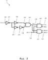
- Fig. 2 an exemplary embodiment of the pulse generator 130 according to the first aspect of the invention is illustrated.
- the implementation of said pulse generator 130 is illustrated with digital logic gates, namely NOT gates or inverters and AND gates.
- digital logic gates namely NOT gates or inverters and AND gates.
- any alternative logic gate arrangements are feasible so long the output results in short pulses from a continuous signal.
- the delayed clock signal 102 is inputted at a first inverter 201 that inverts the polarity of the delayed clock signal 102.
- the output of the first inverter 201 acts as a common node, which serves two propagation paths 205,206.
- the output of the first inverter 201 passes through a second inverter 202 along the propagation path 205, reverting the polarity again that results in the delayed clock signal 102, along with the propagation delay caused by the first and second inverter 201,202, respectively.
- the output of the first inverter 201 is inverted twice, by a third inverter 203 and a fourth inverter 204, respectively. This results in the delayed clock signal 102 with an opposite polarity along with propagation delay caused by the first inverter 201, the third inverter 203 and the fourth inverter 204.
- the signals at the propagation paths 205,206 are fed to a first AND gate 207.
- the signal at the propagation path 205 has an opposite polarity than the signal at the propagation path 206, however with the additional delay caused by the fourth inverter 204, the signals will have same polarity for a brief moment, especially defined by the delay time cause by each delay stage of the inverters 201,202,203,204,205.
- the AND gate output will be high and will produce a pulse or injection pulse 208 with a width corresponding to the delay time of each inverter delay stage.
- the injection pulse 208 is then fed to a second AND gate 209 where the second input of said AND gate 209 is the phase select signal 103. Therefore, the output 104 of the second AND gate 209 will be high when the phase select signal 103 is high. Additionally, the injection pulse 208 is fed to a third AND gate 210 where the second input of said AND gate 210 is also the phase select signal, however with an opposite polarity, i.e. inverted via an inverter in-between. Therefore, the output 105 of the third AND gate will be high when the phase select signal 103 is low. In order to facilitate complementary arrangements, e.g. CMOS implementation, the outputs 104, 105 of the second AND gate 209 and the third AND gate 210, respectively, are further inverted.
- the outputs 104 of the second AND gate 209 are shown as INJ 0P and INJ ON for P-type and N-type transistors, respectively, in CMOS configuration.
- the outputs 105 of the third AND gate 210 are shown as INJ 180P and INJ 180N for P-type and N-type transistors, respectively, in CMOS configuration.
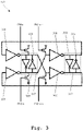
- FIG. 3 an exemplary embodiment of the oscillator 140 according to the first aspect of the invention is illustrated. Particularly, Fig. 3 shows the injection scheme for injecting the injection pulses at different phases of the oscillator 140.
- the first inverter 301 results a first stage output 106
- the second inverter 302 results a second stage output 317
- the third inverter 303 results a third stage output 107
- the fourth inverter 304 results a fourth stage output 316.
- the first stage output 106 and the third stage output 107 carry complementary waveforms and so do the second stage output 317 and the fourth stage output 316.
- the latter two are 90° out of phase with respect to the former two.
- the oscillator 140 consists of four one-pole stages, thereby generating 90° phase separations between consecutive nodes when oscillates.
- the outputs 106,317,107,316 prefer to latch up and then the loop can indefinitely maintain the first stage output 106 and the third stage output 107 high, and the second stage output 317 and the fourth stage output 316 low, or vice versa.
- a first pair of cross-coupled inverters 305 is included between the first stage output 106 and the third stage output 107 and further a second pair of cross-coupled inverters 306 is included between the second stage output 317 and the fourth stage output 316.
- the first pair of cross-coupled inverters 305 and the second pair of cross-coupled inverters 306 prevent equal logical states at their respective input and output nodes.
- the injection pulses INJ 0P , INJ ON and INJ 180P , INJ 180N are injected in a complementary arrangement at the respective phases of the oscillator 140.
- the injection pulse INJ 0P is injected at the first stage output 106 whereas the injection pulse INJ ON is injected at the third stage output 107, which carries complementary waveform to the first stage output 106.
- the injection pulse INJ 180P is injected at the third stage output 107 whereas the injection pulse INJ 180N is injected at the first stage output 106, which carries complementary waveform to the second stage output 107.
- the RF signals from the first stage output 106 correspond to RF signals at phase 0 of the oscillator 140 and the RF signals from the third stage output 107 correspond to RF signals at phase 180 of the oscillator 140.
- said injection principle can be analogously implemented for the second stage output 317 and the fourth stage output 316, thereby injection locking the oscillator 140 at phases 90 and 270, respectively.
- the signal CLK represents the clock input signal 101 of the DCDL 110 and the signal O DCDL represents the delayed clock signal 102.
- the signal SEL ED represents the phase select signal 103 with random sequences for the polarity of the signal.
- the signal INJ 0 and INJ 180 represent the injection pulses 104 and 106, respectively, generated by the pulse generator 130. It can be seen that, the injection pulses INJ 0 are generated when SEL ED is high and the injection pulses INJ 180 are generated when SEL ED is low.
- the signal RF 0 represents the RF signals at the phase 0 of the oscillator 140 and the signal RF 180 represents the RF signals at the phase 180 of the oscillator 140. It can be seen that, when SEL ED is high, the injection pulses INJ 0 are injected at the phase 0 of the oscillator 140 as a clean reference pulse to reset RF 0 . Further, when SEL ED is low, the injection pulses INJ 180 are injected at the phase 180 of the oscillator 140 as a clean reference pulse to reset RF 180 .
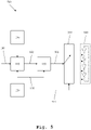
- a second exemplary embodiment of the circuit 500 according to the first aspect of the invention is illustrated.
- the circuit 500 differs from the circuit 100 of Fig. 1 in that the circuit 500 comprises a multi-phase oscillator 540 and additional switching means 510 in order to drive the injection pulses 501 to a respective phase of the oscillator 540.
- the multi-phase oscillator 540 can be a multi-stage ring oscillator, a multi-stage LC oscillator, or any oscillators operable with a minimum phase separation of pi/N, where N is an integer greater than 1, preferably an even integer.
- the switching means 510 is configured to be operable via a random switching logic 503, preferably generated by the edge selector 120.
- the edge selector may further tune the DCDL 110 based on the random switching logic 503, for instance via normalization, in order to synchronize the injection pulses 501 with the respective phases of the multi-phase oscillator 540.
- DPLL 600 digital phase locked loop
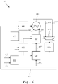
- Said DPLL 600 comprises a reference clock signal 601, preferably generated from an on-board crystal oscillator (not shown), and a digital to time converter (DTC) 610.
- the DTC 610 generates a delayed reference clock signal 602 by delaying the reference clock signal 601.
- the DPLL 600 further comprises the circuit 100 according to the first aspect of the invention, downstream to the DTC 610 so that the circuit 100 is able to take the delayed reference clock signal 602 as its input clock signal.
- the DPLL 600 further comprises the oscillator 140 that generates RF signals at phases 0 and 180, for example, as described along Fig. 3 .
- the circuit 100 generates injection pulses 604,605 from the delayed reference clock signal 602 for the two phases of the oscillator 140.
- the oscillator 140 outputs RF signals at two phases 606,607 that are reset by the injection pulses 604,605 and are further fed to a multiplexer 620.
- the multiplexer 620 is implemented as, for instance a 2x1 multiplexer, which takes the RF signals at inputs and outputs a selective RF signal 608 out of the two based on a control signal.
- Said control signal is preferably the phase select signal 103 provided by the edge selector 120.
- the multiplexer 620 when the phase select signal 103 is high, the multiplexer 620 will output the RF signal at phase 0 of the oscillator 140 and when the phase select signal 103 is low, the multiplexer 620 will output the RF signal at phase 180 of the oscillator.
- the DPLL 600 further comprises a time to digital converter (TDC) 630 that compares an edge of the delayed reference clock signal 602 at the output of DTC 610 with an edge of the RF signals 606,607 at the output 608 of the multiplexer 620. Therefore, the TDC 630 generates an error signal based on the difference between the edges, i.e. phase difference, of said signals.
- the error signal is fed to a loop filter 640 through a feedback path 609, where the loop filter 640 tunes the oscillator 140 based on said error signal.
- the DPLL 600 would align the phases between the output 602 of the DTC 610 and the output 608 of the multiplexer 620 with a random pattern.
- the DTC output 602 sometimes may align with the oscillator phase RF 0 and sometimes may align with RF 180 in a random manner.
- the injection pulses may sometimes be sent to the opposite RF edge if the DTC output 602 is directly used to generate the injection pulses without any compensation for said random patterns. This may result in huge disturbances to the oscillator 140 and may cause large spurious.
- the proposed random edge injection technique allows the DPLL 600 to align the DTC output 602, for instance with rising edges of RF 180 when the phase select signal 103 is high, and, for instance with rising edges of RF 0 when the phase select signal 103 is low.
- the proposed random edge injection technique further ensures the polarity of the injection signals as described along Fig. 2 and Fig. 3 , so that the injection pulses INJ 0P and INJ ON are generated if the phase select signal 103 is high otherwise the injection pulses INJ 180P and INJ 180N are generated.
- the DPLL 600 further comprises an accumulator 660 that comprises a control input 611 and a data input 612.
- the control input 611 corresponds to frequency control input, e.g. a frequency control word (FCW) and the data input 612 corresponds to the transmission data, especially during modulation.
- the accumulator 660 generally comprises a counter or counters for counting, e.g. the edges of the oscillator 140 in one reference clock to coarsely tune the oscillator 140 to the target frequency.
- the accumulator 660 is disabled during the fine-tuning of the oscillator 140, i.e. the correction of the phase error between the RF edge 608 and the delayed reference edge 602.
- the DPLL 600 further comprises so-called estimators 650, which estimate and further calibrate, for instance, the duty cycle of the reference clock signal 601 (crystal oscillator duty cycle), the duty cycle of the oscillator 140, static timing offset for the DCDL, and so on.
- the DPLL 600 further comprises injection control means 670 that is configured to control the generation of the injection pulses 604,605 at the pulse generator 130.
- the injection control means enables or disables the injection path for a selective number of cycles or periods of the reference clock signal 601. The operation of said injection control means will be described in a later section in detail.
- the reference clock signal 601 is generated from a crystal oscillator (not shown) at a clock frequency of 64MHz and the DTC 610 generates the delayed reference clock signal 602 at a clock frequency of 128MHz (i.e. double edge).
- the DCDL 110 takes in the delayed reference clock signal 602 and further delays the signal 602.
- the DCDL output 603 is fed to the pulse generator 130 along with the phase select signal 613 coming from the edge selector 120.
- the pulse generator 130 generates a set of injection pulses 604 for the phase 0 of the oscillator 140 and a set of injection pulses 605 for the phase 180 of the oscillator 140 from the DCDL output 110 and the phase select signal 613.
- the oscillator 140 therefore generates RF signals, which are already reset by the injection pulses, particularly the RF signal at the phase 0 of the oscillator 606 and the RF signal at the phase 180 of the oscillator 607.
- the multiplexer 620 outputs the respective pulses 606,607 to the TDC 630 with respect to the phase select signal 613.
- the TDC 630 generates phase error signals by comparing the edges of the DTC output 602 with the respective RF signals 606,607 and feeds to the loop filter 640 via the feedback path 609.
- the loop filter 640 generates oscillator tuning words correspond to the phase error in order to tune the oscillator phases.
- the phase error signals are further fed to the estimators 710,720,730.
- the estimator 710 estimates and/or calibrates the duty cycles of crystal oscillator and the oscillator 140 and further tunes the DTC edges.
- the estimator 720 estimates and/or calibrates the static timing offset of the DCDL and the duty cycle of the oscillator 140 in order to tune the DCDL 110.
- the estimator 730 estimates or calibrates the DPLL 600 for the modulation of the transmitting data, especially when the DPLL 600 operates in the transmitter mode.
- Fig. 8A shows the operation phases of the DPLL 600 over the required lock time.
- the DPLL 600 uses the accumulator 660, especially the counter, to count the edges of the oscillator 140 in one reference clock to coarsely tune the oscillator 140 close to the target frequency. Then the counter is disabled to reduce power consumption and the fine tuning of the oscillator 140 stats correcting the phase error between the RF edge 608 and the delayed reference edge 602, where the phase error is measured by the TDC 630.
- the TDC output i.e. the phase error
- the injection path is enabled and the phase-locking path is frozen to avoid racing conditions between the two loops.
- the TDC output i.e. the phase error
- the phase-locking path and the injection path are enabled while the aforementioned calibrations are running in the background in order to decrease the level of spurious tones.
- Fig. 8B shows the timing diagram for the operations of the DPLL 600.
- the signal REF represents the reference clock signal 601.
- the signal O DTC represents the DTC output, i.e. the delayed reference clock signal 602.
- the signal O DCDL represents the DCDL output, i.e. the further delayed reference clock signal 603.
- the signal SEL ED represents the phase select signal 613 generated from the edge selector 120.
- the signal INJ 0 represents the injection pulses 604 to be injected at the phase 0 of the oscillator 140 and the signal INJ 180 represents the injection pulses 605 to be injected at the phase 180 of the oscillator 140.
- the signal RF 0 represents the RF signal 606 from the oscillator 140 at the phase 0 and the signal RF 180 represents the RF signal 607 from the oscillator 140 at the phase 180.
- the DPLL 600 aligns O DTC with rising edges of the RF 180 when the SEL ED is high and with rising edges of the RF 0 when the SEL ED is low.
- the proposed random edge injection technique further ensures the polarity of the injection signals such that the injection pulses INJ 0 are generated when SEL ED is high and the injection pulses INJ 180 are generated when SEL ED is low.
- the random pattern of the DTC output 602 is effectively compensated, thereby eliminating any erroneous alignment between the phases of the O DTC and the RF signals.
- Fig. 9A shows an exemplary embodiment of the injection control means 670 in a simplified block diagram, where the components of the DPLL 600 are simplified into three basic blocks in order not to repeat the DPLL 600 operation as described along Fig. 6 and Fig. 7 .
- the injection control means 670 comprises a number pool 901 that is configured to select a number N 902 from a pool of numbers with a geometric distribution for selection. It is conceivable that the pool of numbers may comprise any random distribution. It is further conceivable that the number pool 901 may select the number N 902 from the pool of numbers in a random manner.
- the injection control means 670 further comprises a nonuniform selector 903 that is configured to generate an enable signal 904 with a pulse duration corresponds to the number of clock periods based on the selected number N 902.
- the pulse generator 130 is then configured such that the pulse generator 130 will be enabled when the enable signal 904 is high and the pulse generator 130 will be disabled when the enable signal 904 is low.
- Fig. 9B shows the timing diagram for the operations performed by the injection control means 670.
- the signal REF represents the reference clock signal.
- the signal N represents the number selected from the number pool 901.
- the signal EN INJ represents the enable signal.
- the signal P INJ represents the injection pulses in general.
- the signal PE represents the phase error from the TDC 630.
- the pulse generator 130 is enabled for 3 cycles of the reference clock REF.
- the TDC 630 compares the phase difference between the reference and the RF signal, and the output is used for tuning as described above. After 3 reference cycles, the EN INJ goes low, therefore no injection pulse is sent to the oscillator 140. At this moment, the TDC output represents the phase (frequency) error of the oscillator 140 and the oscillator frequency is tuned, which further reduces the reference spur level. After that, a new number N is selected, e.g. 5 as shown, in order to prevent quasi static states from occurring.
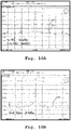
- Fig. 10A and Fig. 10B measurement results are illustrated for the output spectrum indicating the spur level reduction by means of the proposed random edge injection technique.
- Fig. 10A shows the fractional spur level for two output spectrums, where the first spectrum 1001 represents the DPLL output without the proposed random edge injection technique and the second spectrum 1002 represents the DPLL output with the proposed random edge injection technique.
- Fig. 10B shows the reference spur level at the DPLL output 1003 where the proposed random edge injection technique is implemented.
- Fig. 10A shows the fractional spur at 2.434GHz where the fractional part is 2MHz. It can be seen that the fractional spur is -34dBc at the DPLL output 1001 if the random edge injection technique is not implemented. Whereas, the fractional spur is -44dBc at the DPLL output 1002 where the proposed random edge injection technique is implemented. From Fig. 10B , it can be seen that the reference spur at the DPLL output is -51dBc.
- a clock signal is provided.
- a delayed clock signal is generated from the clock signal.
- a phase select signal is generated with a random pulse sequence.
- injection pulses are generated from the delayed clock signal for at least two phases of the oscillator based on the phase select signal.
- a first set of injection pulses are generated for one phase of the at least two phases of the oscillator when the phase select signal is high and a second set of injection pulses are generated for other phase of the at least two phases of the oscillator when the phase select signal is low.
- the embodiments of the present invention can be implemented by hardware, software, or any combination thereof.
- Various embodiments of the present invention may be implemented by one or more application specific integrated circuits (ASICs), digital signal processors (DSPs), digital signal processing devices (DSPDs), programmable logic devices (PLDs), field programmable gate arrays (FPGAs), processors, controllers, microcontrollers, microprocessors, or the like.
- ASICs application specific integrated circuits
- DSPs digital signal processors
- DSPDs digital signal processing devices
- PLDs programmable logic devices
- FPGAs field programmable gate arrays
- processors controllers, microcontrollers, microprocessors, or the like.
Landscapes
- Stabilization Of Oscillater, Synchronisation, Frequency Synthesizers (AREA)
Abstract
Description
- The invention relates to injection locking techniques for injection-locked digital phase locked loop (IL-DPLLs), especially for DPLLs that support frequency modulation in Bluetooth Low Energy (BLE) technology.
- The BLE technology is widely deployed in Internet-of-Things (IoT) applications due to its low energy consumption. Generally, a phase locked loop (PLL) which can support frequency modulation needs to be implemented in BLE systems. In order to reduce the die area of a BLE transceiver, small area oscillators are implemented along with injection-locking techniques in order to suppress the phase noise performance of the oscillators. Moreover, the system often requires the clock generator to support fractional-N mode. This makes the possibility for the system to tune the frequency offset of the crystal oscillator and enables the clock generator to generate small frequency step without using very small oscillator frequency.
- For example, the
document EP 3 249 817 A1 shows a DTC-based PLL operable at fractional-N mode with an improved PLL output spectral purity. However, during the fractional-N, the delay of the DTC changes periodically and the period depends on the fractional part of the frequency control word (FCW). Thus, the non-linearity of the DTC introduces periodic error and this error leads to fractional spur at the output spectrum. In addition the frequency offset of the oscillator and the timing error between the injection path and the PLL path generate periodic error lead to reference spur at the output spectrum. - Accordingly, an object of the invention is to provide a circuit, a digital phase locked loop and a method that can overcome the aforementioned limitations.
- The object is solved by the features of the claim 1 for the circuit, by the features of the claim 8 for the digital phase locked loop and by the features of the claim 13 for the method. The dependent claims contain further developments.
- According to a first aspect of the invention, a circuit for facilitating random edge injection locking of an oscillator is provided. The circuit comprises a clock signal and a digitally controlled delay line, where said digitally controlled delay line is configured to delay the clock signal, thereby generating a delayed clock signal. The circuit further comprises an edge selector configured to generate a phase select signal with a random pulse sequence.
- Moreover, the circuit preferably comprises a pulse generator downstream to the digitally controlled delay line configured to generate injection pulses from the delayed clock signal for at least two phases of the oscillator based on the phase select signal. Therefore, the injection pulses are no longer injected to a fixed phase of the oscillator. Rather, the pulses are injected to different phases of the oscillator in order to break the repeating patterns that cause the spurs.
- Preferably, the pulse generator is further configured to generate a first set of injection pulses for one phase of the at least two phases of the oscillator when the phase select signal is high and a second set of injection pulses for other phase of the at least two phases of the oscillator when the phase select signal is low.
- For instance, the oscillator may generate RF signals at 90 degrees phase separation, i.e. at
phases 0, 90, 180 and 270. In this regard, the pulse generator may generate a first set of pulses for the RF signals at phase 0 and a second set of pulses for the RF signals atphase 180, for example. Using the signal level of the phase select signal as a control input, the respective sets of pulses are injected to the respective phases of the oscillator. This advantageously facilitates the injection of the injection pulses at different phases of the oscillator in a simplified and an effective manner. - Preferably, the circuit further comprises control means configured to tune a delay of the digitally controlled delay line based on a duty cycle of the clock signal in order to compensate at least one half of oscillator period when injecting the injection pulses from one phase to the other phase of the at least two phases of the oscillator. This advantageously prevents the injection of pulses at an opposite or unwanted phase of the oscillator.
- Further preferably, the edge selector comprises a pseudo-random binary sequence generator and the phase select signal preferably comprises a pseudo-random binary sequence. Therefore, random selection of phases of the oscillator to be injected is incorporated.
- Preferably, the oscillator is an inverter-based oscillator, preferably an inverter-based ring oscillator, more preferably a quadrature four-stage ring oscillator operable with a minimum phase separation equal to pi/2. Advantageously, the proposed random edge injection locking technique can be implemented in a cost-effective manner due to the smaller area of the oscillator.
- Further preferably, the oscillator is a multi-phase oscillator and wherein the pulse generator is configured to generate injection pulses for phases of the multi-phase oscillator based on the phase select signal. In this regard, the circuit further comprises switching means downstream to the pulse generator in order to inject the injection pulses at the phases of the multi-phase oscillator, and wherein the switching means is configured to be operable via a random switching logic. Advantageously, the proposed solution can be implemented with oscillators operable with a minimum phase separation of pi/N, where N is an even integer.
- According to a second aspect of the invention, a digital phase locked loop (DPLL) is provided. The DPLL comprises a reference clock signal, and a digital to time converter. Said digital to time converter is configured to delay the reference clock signal, thereby generating a delayed reference clock signal. The DPLL further comprises an oscillator configured to generate radio frequency signals at at least two phases. Furthermore, the DPLL comprises a time to digital converter configured to generate an error signal by comparing an edge of the delayed reference clock signal and an edge of the radio frequency signals.
- Moreover, the DPLL comprises a circuit configured to input the delayed reference clock signal and further to perform random edge injection locking of the oscillator according to the first aspect of the invention. Preferably, the DPLL further comprises a feedback path from the time to digital converter to a loop filter, and wherein the loop filter is configured to tune the oscillator based on the error signal generated by the time to digital converter.
- Therefore, the digital to time converter delays the reference signal where the delayed reference signal phase is compared to the phase of the RF signals of the oscillator in order to phase-lock the oscillator output. On the other hand, the circuit, especially the digitally controlled delay line, takes the delayed reference clock signal as clock signal input and further delays the delayed reference clock signal. The latter is preferably used by the pulse generator along with the phase select signal in order to generate and further to inject pulses at different phases of the oscillator, thereby resetting the noisy phase in the oscillator.
- Further preferably, the DPLL further comprises injection control means configured to control the generation of injection pulses at the pulse generator. In this regard, the injection control means is further configured to enable or disable the generation of injection pulses at the pulse generator for a predefined number of cycles of the reference clock signal. This advantageously keeps the balance between the reference spur and the effectiveness of the proposed random edge injection locking scheme, especially by disabling the injection in different numbers of reference cycles.
- Preferably, the digital phase locked loop is an injection-locked fractional-N digital phase locked loop, preferably, an injection-locked ring-oscillator based fractional-N digital phase locked loop. Advantageously, the proposed DPLL supports BLE technology, especially the Gaussian-FSK modulation, and further provides a cost-effective solution due to the smaller size oscillator.
- According to a third aspect of the invention, a method for facilitating random edge injection locking of an oscillator is provided. The method comprises the steps of providing a clock signal, generating a delayed clock signal, generating a phase select signal with a random pulse sequence, and generating injection pulses from the delayed clock signal for at least two phases of the oscillator based on the phase select signal. Therefore, the injection pulses are injected to different phases of the oscillator in order to break the repeating patterns, thereby suppressing the level of reference spur and fractional spur effectively.
- Preferably, the method further comprises the step of generating a first set of injection pulses for one phase of the at least two phases of the oscillator when the phase select signal is high. In addition, the method further comprises the step of generating a second set of injection pulses for another phase of the at least two phases of the oscillator when the phase select signal is low. This advantageously facilitates the injection of the injection pulses at different phases of the oscillator in a simplified and an effective manner.
- Preferably, the method further comprises the step of compensating at least one half of an oscillator period when injecting the injection pulses from one phase to the other phase of the at least two phases of the oscillator. This advantageously prevents the injection of pulses at an opposite or unwanted phase of the oscillator.
- Exemplary embodiments of the invention are now further explained with respect to the drawings by way of example only, and not for limitation. In the drawings:
- Fig. 1
- shows a first exemplary embodiment of the circuit according to the first aspect of the invention;
- Fig. 2
- shows an exemplary embodiment of the pulse generator according to the first aspect of the invention;
- Fig. 3
- shows an exemplary embodiment of the oscillator according to the first aspect of the invention;
- Fig. 4
- shows an exemplary timing diagram of operations according to the first aspect of the invention;
- Fig. 5
- shows a second exemplary embodiment of the circuit according to the first aspect of the invention;
- Fig. 6
- shows an exemplary embodiment of the digital phase locked loop according to the second aspect of the invention;
- Fig. 7
- shows the digital phase locked loop of
Fig. 6 in detail; - Fig. 8A
- shows exemplary operation phases of the digital phase locked loop according to the second aspect of the invention;
- Fig. 8B
- shows an exemplary timing diagram of operations of the digital phase locked loop according to the second aspect of the invention;
- Fig. 9A
- shows an exemplary embodiment of the injection control means according to the second aspect of the invention;
- Fig. 9B
- shows an exemplary timing diagram of operations of the injection control means of
Fig. 9A ; - Fig. 10A
- shows measurement results for fractional spur level at the output spectrum;
- Fig. 10B
- shows measurement results for reference spur level at the output spectrum; and
- Fig. 11
- shows an exemplary embodiment of the method according to the third aspect of the invention.
- Reference will now be made in detail to the embodiments of the present invention, examples of which are illustrated in the accompanying drawings. However, the following embodiments of the present invention may be variously modified and the range of the present invention is not limited by the following embodiments.
- In
Fig. 1 , a first exemplary embodiment of thecircuit 100 according to the first aspect of the invention is illustrated. Thecircuit 100 comprises aclock signal 101 that is fed to a digitally controlled delay line orDCDL 110, where theDCDL 110 generates a delayed clockedsignal 102 by delaying theclock signal 101. Thecircuit 100 further comprises anedge selector 120 that generates a phaseselect signal 103 with a random pulse sequence. Preferably, theedge selector 120 comprises a pseudo-random binary sequence generator that generates a pseudo-random binary sequence, i.e. PRBS-k as the phaseselect signal 103, where k defines the size of a unique word of data in the sequence. However, other random sequences, e.g., true random sequences, chaotic sequences and the like, as known in the art can also be implemented in order to generate the phaseselect signal 103. - The
circuit 100 further comprises apulse generator 130 downstream to theDCDL 110 and anoscillator 140 downstream to thepulse generator 130. Saidoscillator 140 is configured to generate radio frequency (RF) signals 106,107 at at least two phases, preferably more. In this regard, thepulse generator 130 generates injection pulses 104,105 from the delayedclock signal 102 for the two phases of theoscillator 140 based on the phaseselect signal 103. The generation of said phaseselect signal 103 and the injection arrangement for theoscillator 140 will be discussed in the later sections in detail. - Therefore, the
circuit 100 effectively solves the two main limitations specially associated with a fractional-N injection-locked oscillator, namely the high reference spur and the high fractional spur at the output spectrum. Thecircuit 100 effectively breaks the repeating patterns of pulse injection, especially by injecting pulses at different phases of theoscillator 140. - For instance, if the above-mentioned injection locking is to be performed for a PLL with fractional-N mode having an injection-locked oscillator, the clock signal may correspond to the reference clock signal and the
DCDL 110 can be extended to have a first DCDL and a second DCDL. The first DCDL (i.e. a digital to time converter) may generate a first delayed reference clock signal by delaying the reference clock signal and the second DCDL may generate a second delayed reference clock signal by delaying the first reference clock signal. Then, thepulse generator 130 may generate the injection pulses 104,105 from the second delayed reference clock signal for the two phases of theoscillator 140 based on the phaseselect signal 103. Therefore, theoscillator 140 will be locked with respect to the first delayed reference clock signal whereas the second delayed reference clock signal is used to generate the injection pulses 104,105. - It is important that when the pulses are sent from one phase to another phase of the
oscillator 140, one-half of the oscillator period needs to be compensated by theDCDL 110. Otherwise, a large error will introduce which, in itself, may cause large spurious at the output spectrum. In order to do so, thecircuit 100 comprises control means 150 that is configured to tune the delay of theDCDL 110 based on the duty cycle of theclock signal 101 or the reference clock signal coming from, for instance, a crystal oscillator. In this regard, the control means 150 is configured to tune theDCDL 110 according to the digital RF duty-cycle of theoscillator 140 and further to perform static timing offset calibration of theDCDL 110 by taking into account the random pulse sequence from theedge selector 120, for instance. - In
Fig. 2 , an exemplary embodiment of thepulse generator 130 according to the first aspect of the invention is illustrated. Here, the implementation of saidpulse generator 130 is illustrated with digital logic gates, namely NOT gates or inverters and AND gates. However, it is to be noted that any alternative logic gate arrangements are feasible so long the output results in short pulses from a continuous signal. During the operation, the delayedclock signal 102 is inputted at afirst inverter 201 that inverts the polarity of the delayedclock signal 102. The output of thefirst inverter 201 acts as a common node, which serves two propagation paths 205,206. The output of thefirst inverter 201 passes through asecond inverter 202 along thepropagation path 205, reverting the polarity again that results in the delayedclock signal 102, along with the propagation delay caused by the first and second inverter 201,202, respectively. - Along the
propagation path 206, the output of thefirst inverter 201 is inverted twice, by athird inverter 203 and afourth inverter 204, respectively. This results in the delayedclock signal 102 with an opposite polarity along with propagation delay caused by thefirst inverter 201, thethird inverter 203 and thefourth inverter 204. The signals at the propagation paths 205,206 are fed to a first ANDgate 207. Due to the inversion stages, the signal at thepropagation path 205 has an opposite polarity than the signal at thepropagation path 206, however with the additional delay caused by thefourth inverter 204, the signals will have same polarity for a brief moment, especially defined by the delay time cause by each delay stage of the inverters 201,202,203,204,205. For this brief moment, the AND gate output will be high and will produce a pulse orinjection pulse 208 with a width corresponding to the delay time of each inverter delay stage. - The
injection pulse 208 is then fed to a second ANDgate 209 where the second input of said ANDgate 209 is the phaseselect signal 103. Therefore, theoutput 104 of the second ANDgate 209 will be high when the phaseselect signal 103 is high. Additionally, theinjection pulse 208 is fed to a third ANDgate 210 where the second input of said ANDgate 210 is also the phase select signal, however with an opposite polarity, i.e. inverted via an inverter in-between. Therefore, theoutput 105 of the third AND gate will be high when the phaseselect signal 103 is low. In order to facilitate complementary arrangements, e.g. CMOS implementation, theoutputs gate 209 and the third ANDgate 210, respectively, are further inverted. InFig. 2 , theoutputs 104 of the second ANDgate 209 are shown as INJ0P and INJON for P-type and N-type transistors, respectively, in CMOS configuration. Similarly, theoutputs 105 of the third ANDgate 210 are shown as INJ180P and INJ180N for P-type and N-type transistors, respectively, in CMOS configuration. - In
Fig. 3 , an exemplary embodiment of theoscillator 140 according to the first aspect of the invention is illustrated. Particularly,Fig. 3 shows the injection scheme for injecting the injection pulses at different phases of theoscillator 140. Theoscillator 140 illustrated herein as a quadrature four-stage ring oscillator having a 90° of phase separation. The four stages correspond to four inverters, namely afirst inverter 301, asecond inverter 302, athird inverter 303 and afourth inverter 304. Thefirst inverter 301 results afirst stage output 106, thesecond inverter 302 results asecond stage output 317, thethird inverter 303 results athird stage output 107 and thefourth inverter 304 results afourth stage output 316. - The
first stage output 106 and thethird stage output 107 carry complementary waveforms and so do thesecond stage output 317 and thefourth stage output 316. In addition, the latter two are 90° out of phase with respect to the former two. Hence, theoscillator 140 consists of four one-pole stages, thereby generating 90° phase separations between consecutive nodes when oscillates. However, the outputs 106,317,107,316 prefer to latch up and then the loop can indefinitely maintain thefirst stage output 106 and thethird stage output 107 high, and thesecond stage output 317 and thefourth stage output 316 low, or vice versa. - In order to prevent said indefinite latch up, a first pair of
cross-coupled inverters 305 is included between thefirst stage output 106 and thethird stage output 107 and further a second pair ofcross-coupled inverters 306 is included between thesecond stage output 317 and thefourth stage output 316. The first pair ofcross-coupled inverters 305 and the second pair ofcross-coupled inverters 306 prevent equal logical states at their respective input and output nodes. - The injection pulses INJ0P, INJON and INJ180P, INJ180N, as shown in
Fig. 2 , are injected in a complementary arrangement at the respective phases of theoscillator 140. In particular, the injection pulse INJ0P is injected at thefirst stage output 106 whereas the injection pulse INJON is injected at thethird stage output 107, which carries complementary waveform to thefirst stage output 106. Similarly, the injection pulse INJ180P is injected at thethird stage output 107 whereas the injection pulse INJ180N is injected at thefirst stage output 106, which carries complementary waveform to thesecond stage output 107. - In other words, the RF signals from the
first stage output 106 correspond to RF signals at phase 0 of theoscillator 140 and the RF signals from thethird stage output 107 correspond to RF signals atphase 180 of theoscillator 140. It is to be noted that said injection principle can be analogously implemented for thesecond stage output 317 and thefourth stage output 316, thereby injection locking theoscillator 140 at phases 90 and 270, respectively. - In
Fig. 4 , an exemplary timing diagram of operations according to the first aspect of the invention is illustrated. The signal CLK represents theclock input signal 101 of theDCDL 110 and the signal ODCDL represents the delayedclock signal 102. The signal SELED represents the phaseselect signal 103 with random sequences for the polarity of the signal. The signal INJ0 and INJ180 represent theinjection pulses pulse generator 130. It can be seen that, the injection pulses INJ0 are generated when SELED is high and the injection pulses INJ180 are generated when SELED is low. - The signal RF0 represents the RF signals at the phase 0 of the
oscillator 140 and the signal RF180 represents the RF signals at thephase 180 of theoscillator 140. It can be seen that, when SELED is high, the injection pulses INJ0 are injected at the phase 0 of theoscillator 140 as a clean reference pulse to reset RF0. Further, when SELED is low, the injection pulses INJ180 are injected at thephase 180 of theoscillator 140 as a clean reference pulse to reset RF180. - In
Fig. 5 , a second exemplary embodiment of thecircuit 500 according to the first aspect of the invention is illustrated. Thecircuit 500 differs from thecircuit 100 ofFig. 1 in that thecircuit 500 comprises amulti-phase oscillator 540 and additional switching means 510 in order to drive theinjection pulses 501 to a respective phase of theoscillator 540. Themulti-phase oscillator 540 can be a multi-stage ring oscillator, a multi-stage LC oscillator, or any oscillators operable with a minimum phase separation of pi/N, where N is an integer greater than 1, preferably an even integer. - The switching means 510 is configured to be operable via a
random switching logic 503, preferably generated by theedge selector 120. In this regard, the edge selector may further tune theDCDL 110 based on therandom switching logic 503, for instance via normalization, in order to synchronize theinjection pulses 501 with the respective phases of themulti-phase oscillator 540. - In
Fig. 6 , an exemplary embodiment of the digital phase locked loop (DPLL) 600 according to the second aspect of the invention is illustrated. SaidDPLL 600 comprises areference clock signal 601, preferably generated from an on-board crystal oscillator (not shown), and a digital to time converter (DTC) 610. TheDTC 610 generates a delayedreference clock signal 602 by delaying thereference clock signal 601. TheDPLL 600 further comprises thecircuit 100 according to the first aspect of the invention, downstream to theDTC 610 so that thecircuit 100 is able to take the delayedreference clock signal 602 as its input clock signal. TheDPLL 600 further comprises theoscillator 140 that generates RF signals atphases 0 and 180, for example, as described alongFig. 3 . - As described along
Fig. 1 , thecircuit 100 generates injection pulses 604,605 from the delayedreference clock signal 602 for the two phases of theoscillator 140. Theoscillator 140 outputs RF signals at two phases 606,607 that are reset by the injection pulses 604,605 and are further fed to amultiplexer 620. Themultiplexer 620 is implemented as, for instance a 2x1 multiplexer, which takes the RF signals at inputs and outputs aselective RF signal 608 out of the two based on a control signal. Said control signal is preferably the phaseselect signal 103 provided by theedge selector 120. Hence, when the phaseselect signal 103 is high, themultiplexer 620 will output the RF signal at phase 0 of theoscillator 140 and when the phaseselect signal 103 is low, themultiplexer 620 will output the RF signal atphase 180 of the oscillator. - The
DPLL 600 further comprises a time to digital converter (TDC) 630 that compares an edge of the delayedreference clock signal 602 at the output ofDTC 610 with an edge of the RF signals 606,607 at theoutput 608 of themultiplexer 620. Therefore, theTDC 630 generates an error signal based on the difference between the edges, i.e. phase difference, of said signals. The error signal is fed to aloop filter 640 through afeedback path 609, where theloop filter 640 tunes theoscillator 140 based on said error signal. - It is to be noted that, if the proposed injection locking technique, as performed by the
circuit 100, is not implemented in theDPLL 600, theDPLL 600 would align the phases between theoutput 602 of theDTC 610 and theoutput 608 of themultiplexer 620 with a random pattern. In other words, theDTC output 602 sometimes may align with the oscillator phase RF0 and sometimes may align with RF180 in a random manner. Hence, the injection pulses may sometimes be sent to the opposite RF edge if theDTC output 602 is directly used to generate the injection pulses without any compensation for said random patterns. This may result in huge disturbances to theoscillator 140 and may cause large spurious. - The proposed random edge injection technique, as facilitated by the
circuit 100, allows theDPLL 600 to align theDTC output 602, for instance with rising edges of RF180 when the phaseselect signal 103 is high, and, for instance with rising edges of RF0 when the phaseselect signal 103 is low. The proposed random edge injection technique further ensures the polarity of the injection signals as described alongFig. 2 andFig. 3 , so that the injection pulses INJ0P and INJON are generated if the phaseselect signal 103 is high otherwise the injection pulses INJ180P and INJ180N are generated. - The
DPLL 600 further comprises anaccumulator 660 that comprises acontrol input 611 and adata input 612. Thecontrol input 611 corresponds to frequency control input, e.g. a frequency control word (FCW) and thedata input 612 corresponds to the transmission data, especially during modulation. Theaccumulator 660 generally comprises a counter or counters for counting, e.g. the edges of theoscillator 140 in one reference clock to coarsely tune theoscillator 140 to the target frequency. Preferably, theaccumulator 660 is disabled during the fine-tuning of theoscillator 140, i.e. the correction of the phase error between theRF edge 608 and the delayedreference edge 602. - The
DPLL 600 further comprises so-calledestimators 650, which estimate and further calibrate, for instance, the duty cycle of the reference clock signal 601 (crystal oscillator duty cycle), the duty cycle of theoscillator 140, static timing offset for the DCDL, and so on. TheDPLL 600 further comprises injection control means 670 that is configured to control the generation of the injection pulses 604,605 at thepulse generator 130. In particular, the injection control means enables or disables the injection path for a selective number of cycles or periods of thereference clock signal 601. The operation of said injection control means will be described in a later section in detail. - In
Fig. 7 , theDPLL 600 ofFig. 6 is illustrated in detail. Thereference clock signal 601 is generated from a crystal oscillator (not shown) at a clock frequency of 64MHz and theDTC 610 generates the delayedreference clock signal 602 at a clock frequency of 128MHz (i.e. double edge). TheDCDL 110 takes in the delayedreference clock signal 602 and further delays thesignal 602. TheDCDL output 603 is fed to thepulse generator 130 along with the phaseselect signal 613 coming from theedge selector 120. Thepulse generator 130 generates a set ofinjection pulses 604 for the phase 0 of theoscillator 140 and a set ofinjection pulses 605 for thephase 180 of theoscillator 140 from theDCDL output 110 and the phaseselect signal 613. - The
oscillator 140 therefore generates RF signals, which are already reset by the injection pulses, particularly the RF signal at the phase 0 of theoscillator 606 and the RF signal at thephase 180 of theoscillator 607. Themultiplexer 620 outputs the respective pulses 606,607 to theTDC 630 with respect to the phaseselect signal 613. TheTDC 630 generates phase error signals by comparing the edges of theDTC output 602 with the respective RF signals 606,607 and feeds to theloop filter 640 via thefeedback path 609. - The
loop filter 640 generates oscillator tuning words correspond to the phase error in order to tune the oscillator phases. The phase error signals are further fed to the estimators 710,720,730. Particularly, theestimator 710 estimates and/or calibrates the duty cycles of crystal oscillator and theoscillator 140 and further tunes the DTC edges. Theestimator 720 estimates and/or calibrates the static timing offset of the DCDL and the duty cycle of theoscillator 140 in order to tune theDCDL 110. Moreover, theestimator 730 estimates or calibrates theDPLL 600 for the modulation of the transmitting data, especially when theDPLL 600 operates in the transmitter mode. - Along
Fig. 8A and Fig. 8B , the operation phases of theDPLL 600 are illustrated. In particular,Fig. 8A shows the operation phases of theDPLL 600 over the required lock time. During the initial phase, theDPLL 600 uses theaccumulator 660, especially the counter, to count the edges of theoscillator 140 in one reference clock to coarsely tune theoscillator 140 close to the target frequency. Then the counter is disabled to reduce power consumption and the fine tuning of theoscillator 140 stats correcting the phase error between theRF edge 608 and the delayedreference edge 602, where the phase error is measured by theTDC 630. - During the PLL only phase, the TDC output, i.e. the phase error, is used to compute or estimate the duty cycle error of the reference clock and the RF signal and further to estimate the gain of the
DTC 610. Next, the injection path is enabled and the phase-locking path is frozen to avoid racing conditions between the two loops. During the injection lock only phase, the TDC output, i.e. the phase error, is used for calibrating the duty cycle of the crystal oscillator and further to tune the delay of theDCDL 110 in order to reduce the static timing offset. Finally, the phase-locking path and the injection path are enabled while the aforementioned calibrations are running in the background in order to decrease the level of spurious tones. -
Fig. 8B shows the timing diagram for the operations of theDPLL 600. The signal REF represents thereference clock signal 601. The signal ODTC represents the DTC output, i.e. the delayedreference clock signal 602. The signal ODCDL represents the DCDL output, i.e. the further delayedreference clock signal 603. The signal SELED represents the phaseselect signal 613 generated from theedge selector 120. The signal INJ0 represents theinjection pulses 604 to be injected at the phase 0 of theoscillator 140 and the signal INJ180 represents theinjection pulses 605 to be injected at thephase 180 of theoscillator 140. The signal RF0 represents the RF signal 606 from theoscillator 140 at the phase 0 and the signal RF180 represents the RF signal 607 from theoscillator 140 at thephase 180. - It can be seen that, by the virtue of the proposed random edge injection technique, the
DPLL 600 aligns ODTC with rising edges of the RF180 when the SELED is high and with rising edges of the RF0 when the SELED is low. The proposed random edge injection technique further ensures the polarity of the injection signals such that the injection pulses INJ0 are generated when SELED is high and the injection pulses INJ180 are generated when SELED is low. As such, the random pattern of theDTC output 602 is effectively compensated, thereby eliminating any erroneous alignment between the phases of the ODTC and the RF signals. - Along
Fig. 9A and Fig. 9B , the operation of the injection control means 670 is illustrated. Particularly,Fig. 9A shows an exemplary embodiment of the injection control means 670 in a simplified block diagram, where the components of theDPLL 600 are simplified into three basic blocks in order not to repeat theDPLL 600 operation as described alongFig. 6 andFig. 7 . Generally, the injection control means 670 comprises anumber pool 901 that is configured to select anumber N 902 from a pool of numbers with a geometric distribution for selection. It is conceivable that the pool of numbers may comprise any random distribution. It is further conceivable that thenumber pool 901 may select thenumber N 902 from the pool of numbers in a random manner. - The injection control means 670 further comprises a
nonuniform selector 903 that is configured to generate an enablesignal 904 with a pulse duration corresponds to the number of clock periods based on the selectednumber N 902. Thepulse generator 130 is then configured such that thepulse generator 130 will be enabled when the enable signal 904 is high and thepulse generator 130 will be disabled when the enable signal 904 is low. -
Fig. 9B shows the timing diagram for the operations performed by the injection control means 670. The signal REF represents the reference clock signal. The signal N represents the number selected from thenumber pool 901. The signal ENINJ represents the enable signal. The signal PINJ represents the injection pulses in general. The signal PE represents the phase error from theTDC 630. - It can be seen that, for example, if the output of the
number pool 901 is updated to 3, thepulse generator 130 is enabled for 3 cycles of the reference clock REF. TheTDC 630 compares the phase difference between the reference and the RF signal, and the output is used for tuning as described above. After 3 reference cycles, the ENINJ goes low, therefore no injection pulse is sent to theoscillator 140. At this moment, the TDC output represents the phase (frequency) error of theoscillator 140 and the oscillator frequency is tuned, which further reduces the reference spur level. After that, a new number N is selected, e.g. 5 as shown, in order to prevent quasi static states from occurring. - Along
Fig. 10A and Fig. 10B , measurement results are illustrated for the output spectrum indicating the spur level reduction by means of the proposed random edge injection technique. In particular,Fig. 10A shows the fractional spur level for two output spectrums, where thefirst spectrum 1001 represents the DPLL output without the proposed random edge injection technique and thesecond spectrum 1002 represents the DPLL output with the proposed random edge injection technique.Fig. 10B shows the reference spur level at theDPLL output 1003 where the proposed random edge injection technique is implemented. -
Fig. 10A shows the fractional spur at 2.434GHz where the fractional part is 2MHz. It can be seen that the fractional spur is -34dBc at theDPLL output 1001 if the random edge injection technique is not implemented. Whereas, the fractional spur is -44dBc at theDPLL output 1002 where the proposed random edge injection technique is implemented. FromFig. 10B , it can be seen that the reference spur at the DPLL output is -51dBc. - In
Fig. 11 , an exemplary embodiment of the method according to the third aspect of the invention is illustrated. In a first step S1, a clock signal is provided. In a second step S2, a delayed clock signal is generated from the clock signal. In a third step S3, a phase select signal is generated with a random pulse sequence. In a fourth step S4, injection pulses are generated from the delayed clock signal for at least two phases of the oscillator based on the phase select signal. - Particularly, a first set of injection pulses are generated for one phase of the at least two phases of the oscillator when the phase select signal is high and a second set of injection pulses are generated for other phase of the at least two phases of the oscillator when the phase select signal is low.
- The embodiments of the present invention can be implemented by hardware, software, or any combination thereof. Various embodiments of the present invention may be implemented by one or more application specific integrated circuits (ASICs), digital signal processors (DSPs), digital signal processing devices (DSPDs), programmable logic devices (PLDs), field programmable gate arrays (FPGAs), processors, controllers, microcontrollers, microprocessors, or the like.
- Although the invention has been illustrated and described with respect to one or more implementations, equivalent alterations and modifications will occur to others skilled in the art upon the reading and understanding of this specification and the annexed drawings. In addition, while a particular feature of the invention may have been disclosed with respect to only one of several implementations, such feature may be combined with one or more other features of the other implementations as may be desired and advantageous for any given or particular application.
Claims (15)
- A circuit (100) for facilitating random edge injection locking of an oscillator (140) comprising:a clock signal (101),a digitally controlled delay line (110) configured to delay the clock signal (101), thereby generating a delayed clock signal (102),an edge selector (120) configured to generate a phase select signal (103) with a random pulse sequence, anda pulse generator (130) downstream to the digitally controlled delay line (110) configured to generate injection pulses (104,105) from the delayed clock signal (102) for at least two phases of the oscillator (140) based on the phase select signal (103).
- The circuit according to claim 1,
wherein the pulse generator (130) is further configured to generate a first set of injection pulses (104) for one phase of the at least two phases of the oscillator (140) when the phase select signal (103) is high and a second set of injection pulses (105) for other phase of the at least two phases of the oscillator (140) when the phase select signal (103) is low. - The circuit according to claim 1 or 2,
wherein the circuit further comprises control means (150) configured to tune a delay of the digitally controlled delay line (110) based on a duty cycle of the clock signal (101) in order to compensate at least one half of oscillator period when injecting the injection pulses (104,105) from one phase to the other phase of the at least two phases of the oscillator (140). - The circuit according to any of claims 1 to 3,
wherein the edge selector (120) comprises a pseudo-random binary sequence generator and the phase select signal (103) preferably comprises a pseudo-random binary sequence. - The circuit according to any of claims 1 to 4,
wherein the oscillator (140) is an inverter-based oscillator, preferably an inverter-based ring oscillator, more preferably a quadrature four-stage ring oscillator operable with a minimum phase separation equal to pi/2. - The circuit according to any claims 1 to 5,
wherein the oscillator is a multi-phase oscillator (540) and wherein the pulse generator (130) is configured to generate injection pulses for phases of the multi-phase oscillator (540) based on the phase select signal (103). - The circuit according to claim 6,
wherein the circuit further comprises switching means (510) downstream to the pulse generator (130) in order to inject the injection pulses at the phases of the multi-phase oscillator (540), and wherein the switching means (510) is configured to be operable via a random switching logic (503). - A digital phase locked loop (600) comprising:a reference clock signal (601),a digital to time converter (610) configured to delay the reference clock signal (601), thereby generating a delayed reference clock signal (602),an oscillator (140) configured to generate radio frequency signals (606,607) at at least two phases,a time to digital converter (630) configured to generate an error signal by comparing an edge of the delayed reference clock signal (602) and an edge of the radio frequency signals (606,607), anda circuit (100) configured to input the delayed reference clock signal (602) and further to perform random edge injection locking of the oscillator (140) according to claims 1 to 7.
- The digital phase locked loop according to claim 8, wherein the digital phase locked loop (600) further comprises a feedback path (609) from the time to digital converter (630) to a loop filter (640), and wherein the loop filter (640) is configured to tune the oscillator (140) based on the error signal generated by the time to digital converter (630).
- The digital phase locked loop according to claim 8 or 9,
wherein the digital phase locked loop (600) further comprises injection control means (670) configured to control the generation of injection pulses at the pulse generator (130). - The digital phase locked loop according to claim 10, wherein the injection control means (670) is further configured to enable or disable the generation of injection pulses at the pulse generator (130) for a predefined number of cycles of the reference clock signal (601).
- The digital phase locked loop according to any of claims 8 to 11,
wherein the digital phase locked loop (600) is an injection-locked fractional-N digital phase locked loop, preferably, an injection-locked ring-oscillator based fractional-N digital phase locked loop. - A method for facilitating random edge injection locking of an oscillator comprises the steps of:providing a clock signal,generating a delayed clock signal,generating a phase select signal with a random pulse sequence, andgenerating injection pulses from the delayed clock signal for at least two phases of the oscillator based on the phase select signal.
- The method according to claim 13,
wherein the method further comprises the steps of:generating a first set of injection pulses for one phase of the at least two phases of the oscillator when the phase select signal is high, andgenerating a second set of injection pulses for other phase of the at least two phases of the oscillator when the phase select signal is low. - The method according to claim 13 or 14,
wherein the method further comprises the step of compensating at least one half of oscillator period when injecting the injection pulses from one phase to the other phase of the at least two phases of the oscillator.
Priority Applications (2)
| Application Number | Priority Date | Filing Date | Title |
|---|---|---|---|
| EP20205829.3A EP3996280B1 (en) | 2020-11-05 | 2020-11-05 | Circuit and method for random edge injection locking |
| US17/401,924 US11342923B1 (en) | 2020-11-05 | 2021-08-13 | Circuit and method for random edge injection locking |
Applications Claiming Priority (1)
| Application Number | Priority Date | Filing Date | Title |
|---|---|---|---|
| EP20205829.3A EP3996280B1 (en) | 2020-11-05 | 2020-11-05 | Circuit and method for random edge injection locking |
Publications (2)
| Publication Number | Publication Date |
|---|---|
| EP3996280A1 true EP3996280A1 (en) | 2022-05-11 |
| EP3996280B1 EP3996280B1 (en) | 2025-07-23 |
Family
ID=73138638
Family Applications (1)
| Application Number | Title | Priority Date | Filing Date |
|---|---|---|---|
| EP20205829.3A Active EP3996280B1 (en) | 2020-11-05 | 2020-11-05 | Circuit and method for random edge injection locking |
Country Status (2)
| Country | Link |
|---|---|
| US (1) | US11342923B1 (en) |
| EP (1) | EP3996280B1 (en) |
Families Citing this family (4)
| Publication number | Priority date | Publication date | Assignee | Title |
|---|---|---|---|---|
| US12348233B2 (en) | 2022-10-31 | 2025-07-01 | Samsung Electronics Co., Ltd. | Frequency multiplier for phase rotation |
| TW202445998A (en) | 2023-04-05 | 2024-11-16 | 南韓商三星電子股份有限公司 | Clock generation device and clock generation method using the same |
| US12451876B2 (en) * | 2024-02-22 | 2025-10-21 | Nvidia Corporation | Asynchronous control of phase shift using an injection-locked-oscillator-based phase rotator |
| US20250373256A1 (en) * | 2024-06-03 | 2025-12-04 | Qualcomm Incorporated | Injection locking oscillator with phase rotation capability |
Citations (5)
| Publication number | Priority date | Publication date | Assignee | Title |
|---|---|---|---|---|
| US9306585B1 (en) * | 2015-02-04 | 2016-04-05 | Xilinx, Inc. | Fractional-N multiplying injection-locked oscillation |
| US9614537B1 (en) * | 2016-04-07 | 2017-04-04 | Xilinx, Inc. | Digital fractional-N multiplying injection locked oscillator |
| EP3249817A1 (en) | 2016-05-25 | 2017-11-29 | IMEC vzw | Dtc-based pll and method for operating the dtc-based pll |
| US10110239B1 (en) * | 2017-10-12 | 2018-10-23 | Oracle International Corporation | Injection-locking PLL with frequency drift tracking and duty-cycle distortion cancellation |
| US20190058480A1 (en) * | 2017-08-15 | 2019-02-21 | Taiwan Semiconductor Manufacturing Company, Ltd. | Injection-locked digital bang-bang phase-locked loop with timing calibration |
Family Cites Families (37)
| Publication number | Priority date | Publication date | Assignee | Title |
|---|---|---|---|---|
| US5451911A (en) * | 1994-04-07 | 1995-09-19 | Media Vision, Inc. | Timing generator |
| PT1382172E (en) * | 2001-03-30 | 2009-01-21 | M & Fc Holding Llc | Enhanced wireless packet data communication system, method, and apparatus apllicable to both wide area networks and local area networks |
| US7545232B2 (en) * | 2007-06-22 | 2009-06-09 | Infineon Technologies Ag | Polar modulator arrangement and polar modulation method |
| KR20090074412A (en) * | 2008-01-02 | 2009-07-07 | 삼성전자주식회사 | Division circuit and phase locked loop using the same |
| US8134411B2 (en) * | 2008-04-17 | 2012-03-13 | Texas Instruments Incorporated | Computation spreading utilizing dithering for spur reduction in a digital phase lock loop |
| US8063669B2 (en) * | 2008-11-06 | 2011-11-22 | Nokia Corporation | Frequency synthesizer having a plurality of independent output tones |
| EP2339753B1 (en) * | 2009-12-24 | 2012-07-04 | Nxp B.V. | A digital phase locked loop |
| US8634512B2 (en) * | 2011-02-08 | 2014-01-21 | Qualcomm Incorporated | Two point modulation digital phase locked loop |
| JP5684076B2 (en) * | 2011-09-06 | 2015-03-11 | 株式会社日立製作所 | Analog to digital converter and radio receiver |
| US8692598B2 (en) * | 2012-02-23 | 2014-04-08 | Lsi Corporation | Digital phase locked loop |
| US8866519B1 (en) * | 2013-02-28 | 2014-10-21 | Pmc-Sierra Us, Inc. | System and method for reducing spectral pollution in a signal |
| US9319051B2 (en) * | 2013-05-28 | 2016-04-19 | Broadcom Corporation | Digital PLL with hybrid phase/frequency detector and digital noise cancellation |
| TWI630798B (en) * | 2014-02-07 | 2018-07-21 | 美商線性科技股份有限公司 | Arbitrary phase trajectory frequency synthesizer |
| US9819356B2 (en) * | 2014-12-15 | 2017-11-14 | Intel IP Corporation | Injection locked ring oscillator based digital-to-time converter and method for providing a filtered interpolated phase signal |
| US9531394B1 (en) * | 2015-06-22 | 2016-12-27 | Silicon Laboratories Inc. | Calibration of digital-to-time converter |
| US11210871B2 (en) * | 2015-08-05 | 2021-12-28 | EZ Lynk SEZC | System and method for remote emissions control unit monitoring and reprogramming |
| US10644708B2 (en) * | 2016-09-30 | 2020-05-05 | Apple Inc. | Method and apparatus for calibration of voltage controlled oscillator |
| KR102589448B1 (en) * | 2017-02-03 | 2023-10-13 | 에스케이하이닉스 주식회사 | Injection locked phase locked loop |
| JP2018157434A (en) * | 2017-03-17 | 2018-10-04 | 株式会社東芝 | Oscillator, integrated circuit, and wireless communication device |
| EP3422580B1 (en) * | 2017-06-28 | 2025-01-01 | Analog Devices, Inc. | Apparatus and methods for clock synchronization and frequency translation |
| DE112018005256T5 (en) * | 2017-09-18 | 2020-07-02 | Intel Corporation | Time-coded data communication protocol, device and method for generating and receiving a data signal |
| US10320401B2 (en) * | 2017-10-13 | 2019-06-11 | Xilinx, Inc. | Dual-path digital-to-time converter |
| US10067478B1 (en) * | 2017-12-11 | 2018-09-04 | Silicon Laboratories Inc. | Use of a recirculating delay line with a time-to-digital converter |
| US11003205B2 (en) * | 2019-02-04 | 2021-05-11 | Sigmasense, Llc. | Receive analog to digital circuit of a low voltage drive circuit data communication system |
| US10659060B2 (en) * | 2018-09-27 | 2020-05-19 | Silicon Laboratories Inc. | Spur cancellation with adaptive frequency tracking |
| US11231741B1 (en) * | 2018-10-11 | 2022-01-25 | Marvell Asia Pte, Ltd. | Systems and methods for generating clock signals |
| US10567154B1 (en) * | 2018-11-21 | 2020-02-18 | The Regents Of The University Of Michigan | Ring oscillator based all-digital Bluetooth low energy transmitter |
| US10862488B2 (en) * | 2018-12-26 | 2020-12-08 | Texas Instruments Incorporated | Time-to-digital converter stop time control |
| US10895850B1 (en) * | 2019-07-25 | 2021-01-19 | Si-Ware Systems S.A.E. | Mixed-domain circuit with differential domain-converters |
| US11121731B2 (en) * | 2019-08-26 | 2021-09-14 | Intel Corporation | Digital radio head control |
| US10819353B1 (en) * | 2019-10-04 | 2020-10-27 | Silicon Laboratories Inc. | Spur cancellation in a PLL system with an automatically updated target spur frequency |
| US10790833B1 (en) * | 2020-03-27 | 2020-09-29 | The Boeing Company | Clock data recovery circuit |
| US11223362B2 (en) * | 2020-05-14 | 2022-01-11 | Mediatek Inc. | Phase-locked loop circuit and digital-to-time convertor error cancelation method thereof |
| KR102451264B1 (en) * | 2020-05-21 | 2022-10-06 | 홍익대학교 산학협력단 | All-digital multiplying delay-locked loop with a delta-sigma dithering cell |
| US11949441B2 (en) * | 2020-07-23 | 2024-04-02 | Intel Corporation | Transmitter and method for generating radio frequency transmit signal, mobile device and base station |
| US11201626B1 (en) * | 2020-09-21 | 2021-12-14 | Samsung Electronics Co., Ltd. | Phase locked loop device and method of operating ihe same |
| US11218158B1 (en) * | 2021-01-21 | 2022-01-04 | Analog Devices International Unlimited Company | Digital estimation of transfer functions in continuous-time analog-to-digital converters |
-
2020
- 2020-11-05 EP EP20205829.3A patent/EP3996280B1/en active Active
-
2021
- 2021-08-13 US US17/401,924 patent/US11342923B1/en active Active
Patent Citations (5)
| Publication number | Priority date | Publication date | Assignee | Title |
|---|---|---|---|---|
| US9306585B1 (en) * | 2015-02-04 | 2016-04-05 | Xilinx, Inc. | Fractional-N multiplying injection-locked oscillation |
| US9614537B1 (en) * | 2016-04-07 | 2017-04-04 | Xilinx, Inc. | Digital fractional-N multiplying injection locked oscillator |
| EP3249817A1 (en) | 2016-05-25 | 2017-11-29 | IMEC vzw | Dtc-based pll and method for operating the dtc-based pll |
| US20190058480A1 (en) * | 2017-08-15 | 2019-02-21 | Taiwan Semiconductor Manufacturing Company, Ltd. | Injection-locked digital bang-bang phase-locked loop with timing calibration |
| US10110239B1 (en) * | 2017-10-12 | 2018-10-23 | Oracle International Corporation | Injection-locking PLL with frequency drift tracking and duty-cycle distortion cancellation |
Also Published As
| Publication number | Publication date |
|---|---|
| US20220140831A1 (en) | 2022-05-05 |
| EP3996280B1 (en) | 2025-07-23 |
| US11342923B1 (en) | 2022-05-24 |
Similar Documents
| Publication | Publication Date | Title |
|---|---|---|
| US11342923B1 (en) | Circuit and method for random edge injection locking | |
| US8531322B2 (en) | Time-to-digital converter | |
| US9170564B2 (en) | Time-to-digital converter and PLL circuit using the same | |
| US9755574B2 (en) | Injection-locked oscillator and method for controlling jitter and/or phase noise | |
| US7495488B2 (en) | Phase-locked loop circuit, delay-locked loop circuit and method of tuning output frequencies of the same | |
| US8228126B2 (en) | Multi-band burst-mode clock and data recovery circuit | |
| US8368439B2 (en) | Phase locked loop circuit, method of detecting lock, and system having the circuit | |
| US20140021987A1 (en) | Injection-locked-type frequency-locked oscillator | |
| US20110074514A1 (en) | Frequency measurement circuit and pll synthesizer provided therewith | |
| US7071750B2 (en) | Method for multiple-phase splitting by phase interpolation and circuit the same | |
| CN108023578B (en) | Quadrature clock generator and communication system transmitter | |
| TWI726791B (en) | Signal divider, signal distribution system, and method thereof | |
| US20090135885A1 (en) | Non-linear feedback control loops as spread spectrum clock generator | |
| US9369139B1 (en) | Fractional reference-injection PLL | |
| US9634677B2 (en) | Clock generator and integrated circuit using the same and injection-locked phase-locked loop control method | |
| KR20080016179A (en) | Clock multiplier and clock multiplication method | |
| Chen et al. | A fast-locking all-digital deskew buffer with duty-cycle correction | |
| JP6481502B2 (en) | Lock detection circuit, oscillation source circuit, and wireless device | |
| US7372340B2 (en) | Precision frequency and phase synthesis with fewer voltage-controlled oscillator stages | |
| US20070285082A1 (en) | Lock Detecting Circuit, Lock Detecting Method | |
| US7498887B1 (en) | High frequency digital oscillator-on-demand with synchronization | |
| JP2013077869A (en) | Time-digital converter and pll circuit | |
| US10230381B2 (en) | Frequency divider | |
| US10560053B2 (en) | Digital fractional frequency divider | |
| JP7482745B2 (en) | Oscillator Circuit |
Legal Events
| Date | Code | Title | Description |
|---|---|---|---|
| PUAI | Public reference made under article 153(3) epc to a published international application that has entered the european phase |
Free format text: ORIGINAL CODE: 0009012 |
|
| STAA | Information on the status of an ep patent application or granted ep patent |
Free format text: STATUS: THE APPLICATION HAS BEEN PUBLISHED |
|
| AK | Designated contracting states |
Kind code of ref document: A1 Designated state(s): AL AT BE BG CH CY CZ DE DK EE ES FI FR GB GR HR HU IE IS IT LI LT LU LV MC MK MT NL NO PL PT RO RS SE SI SK SM TR |
|
| STAA | Information on the status of an ep patent application or granted ep patent |
Free format text: STATUS: REQUEST FOR EXAMINATION WAS MADE |
|
| 17P | Request for examination filed |
Effective date: 20221017 |
|
| RBV | Designated contracting states (corrected) |
Designated state(s): AL AT BE BG CH CY CZ DE DK EE ES FI FR GB GR HR HU IE IS IT LI LT LU LV MC MK MT NL NO PL PT RO RS SE SI SK SM TR |
|
| GRAP | Despatch of communication of intention to grant a patent |
Free format text: ORIGINAL CODE: EPIDOSNIGR1 |
|
| STAA | Information on the status of an ep patent application or granted ep patent |
Free format text: STATUS: GRANT OF PATENT IS INTENDED |
|
| INTG | Intention to grant announced |
Effective date: 20250402 |
|
| GRAS | Grant fee paid |
Free format text: ORIGINAL CODE: EPIDOSNIGR3 |
|
| GRAA | (expected) grant |
Free format text: ORIGINAL CODE: 0009210 |
|
| STAA | Information on the status of an ep patent application or granted ep patent |
Free format text: STATUS: THE PATENT HAS BEEN GRANTED |
|
| AK | Designated contracting states |
Kind code of ref document: B1 Designated state(s): AL AT BE BG CH CY CZ DE DK EE ES FI FR GB GR HR HU IE IS IT LI LT LU LV MC MK MT NL NO PL PT RO RS SE SI SK SM TR |
|
| REG | Reference to a national code |
Ref country code: GB Ref legal event code: FG4D |
|
| REG | Reference to a national code |
Ref country code: CH Ref legal event code: EP |
|
| REG | Reference to a national code |
Ref country code: DE Ref legal event code: R096 Ref document number: 602020054923 Country of ref document: DE |
|
| REG | Reference to a national code |
Ref country code: IE Ref legal event code: FG4D |
|
| P01 | Opt-out of the competence of the unified patent court (upc) registered |
Free format text: CASE NUMBER: APP_32298/2025 Effective date: 20250703 |
|
| REG | Reference to a national code |
Ref country code: NL Ref legal event code: MP Effective date: 20250723 |
|
| PG25 | Lapsed in a contracting state [announced via postgrant information from national office to epo] |
Ref country code: PT Free format text: LAPSE BECAUSE OF FAILURE TO SUBMIT A TRANSLATION OF THE DESCRIPTION OR TO PAY THE FEE WITHIN THE PRESCRIBED TIME-LIMIT Effective date: 20251124 |
|
| PG25 | Lapsed in a contracting state [announced via postgrant information from national office to epo] |
Ref country code: NL Free format text: LAPSE BECAUSE OF FAILURE TO SUBMIT A TRANSLATION OF THE DESCRIPTION OR TO PAY THE FEE WITHIN THE PRESCRIBED TIME-LIMIT Effective date: 20250723 |
|
| REG | Reference to a national code |
Ref country code: AT Ref legal event code: MK05 Ref document number: 1817517 Country of ref document: AT Kind code of ref document: T Effective date: 20250723 |
|
| PG25 | Lapsed in a contracting state [announced via postgrant information from national office to epo] |
Ref country code: IS Free format text: LAPSE BECAUSE OF FAILURE TO SUBMIT A TRANSLATION OF THE DESCRIPTION OR TO PAY THE FEE WITHIN THE PRESCRIBED TIME-LIMIT Effective date: 20251123 |
|
| PGFP | Annual fee paid to national office [announced via postgrant information from national office to epo] |
Ref country code: DE Payment date: 20251022 Year of fee payment: 6 |
|
| PG25 | Lapsed in a contracting state [announced via postgrant information from national office to epo] |
Ref country code: NO Free format text: LAPSE BECAUSE OF FAILURE TO SUBMIT A TRANSLATION OF THE DESCRIPTION OR TO PAY THE FEE WITHIN THE PRESCRIBED TIME-LIMIT Effective date: 20251023 |
|
| REG | Reference to a national code |
Ref country code: LT Ref legal event code: MG9D |
|
| PG25 | Lapsed in a contracting state [announced via postgrant information from national office to epo] |
Ref country code: AT Free format text: LAPSE BECAUSE OF FAILURE TO SUBMIT A TRANSLATION OF THE DESCRIPTION OR TO PAY THE FEE WITHIN THE PRESCRIBED TIME-LIMIT Effective date: 20250723 |
|
| PG25 | Lapsed in a contracting state [announced via postgrant information from national office to epo] |
Ref country code: FI Free format text: LAPSE BECAUSE OF FAILURE TO SUBMIT A TRANSLATION OF THE DESCRIPTION OR TO PAY THE FEE WITHIN THE PRESCRIBED TIME-LIMIT Effective date: 20250723 |
|
| PG25 | Lapsed in a contracting state [announced via postgrant information from national office to epo] |
Ref country code: HR Free format text: LAPSE BECAUSE OF FAILURE TO SUBMIT A TRANSLATION OF THE DESCRIPTION OR TO PAY THE FEE WITHIN THE PRESCRIBED TIME-LIMIT Effective date: 20250723 |
|
| PG25 | Lapsed in a contracting state [announced via postgrant information from national office to epo] |
Ref country code: GR Free format text: LAPSE BECAUSE OF FAILURE TO SUBMIT A TRANSLATION OF THE DESCRIPTION OR TO PAY THE FEE WITHIN THE PRESCRIBED TIME-LIMIT Effective date: 20251024 |
|
| PG25 | Lapsed in a contracting state [announced via postgrant information from national office to epo] |
Ref country code: SE Free format text: LAPSE BECAUSE OF FAILURE TO SUBMIT A TRANSLATION OF THE DESCRIPTION OR TO PAY THE FEE WITHIN THE PRESCRIBED TIME-LIMIT Effective date: 20250723 |
|
| PG25 | Lapsed in a contracting state [announced via postgrant information from national office to epo] |
Ref country code: LV Free format text: LAPSE BECAUSE OF FAILURE TO SUBMIT A TRANSLATION OF THE DESCRIPTION OR TO PAY THE FEE WITHIN THE PRESCRIBED TIME-LIMIT Effective date: 20250723 |
|
| PG25 | Lapsed in a contracting state [announced via postgrant information from national office to epo] |
Ref country code: BG Free format text: LAPSE BECAUSE OF FAILURE TO SUBMIT A TRANSLATION OF THE DESCRIPTION OR TO PAY THE FEE WITHIN THE PRESCRIBED TIME-LIMIT Effective date: 20250723 Ref country code: PL Free format text: LAPSE BECAUSE OF FAILURE TO SUBMIT A TRANSLATION OF THE DESCRIPTION OR TO PAY THE FEE WITHIN THE PRESCRIBED TIME-LIMIT Effective date: 20250723 |
|
| PG25 | Lapsed in a contracting state [announced via postgrant information from national office to epo] |
Ref country code: RS Free format text: LAPSE BECAUSE OF FAILURE TO SUBMIT A TRANSLATION OF THE DESCRIPTION OR TO PAY THE FEE WITHIN THE PRESCRIBED TIME-LIMIT Effective date: 20251023 |
|
| PG25 | Lapsed in a contracting state [announced via postgrant information from national office to epo] |
Ref country code: ES Free format text: LAPSE BECAUSE OF FAILURE TO SUBMIT A TRANSLATION OF THE DESCRIPTION OR TO PAY THE FEE WITHIN THE PRESCRIBED TIME-LIMIT Effective date: 20250723 |
|
| PG25 | Lapsed in a contracting state [announced via postgrant information from national office to epo] |
Ref country code: RO Free format text: LAPSE BECAUSE OF FAILURE TO SUBMIT A TRANSLATION OF THE DESCRIPTION OR TO PAY THE FEE WITHIN THE PRESCRIBED TIME-LIMIT Effective date: 20250723 |
|
| PG25 | Lapsed in a contracting state [announced via postgrant information from national office to epo] |
Ref country code: SM Free format text: LAPSE BECAUSE OF FAILURE TO SUBMIT A TRANSLATION OF THE DESCRIPTION OR TO PAY THE FEE WITHIN THE PRESCRIBED TIME-LIMIT Effective date: 20250723 |
|
| PG25 | Lapsed in a contracting state [announced via postgrant information from national office to epo] |
Ref country code: DK Free format text: LAPSE BECAUSE OF FAILURE TO SUBMIT A TRANSLATION OF THE DESCRIPTION OR TO PAY THE FEE WITHIN THE PRESCRIBED TIME-LIMIT Effective date: 20250723 |
|
| PG25 | Lapsed in a contracting state [announced via postgrant information from national office to epo] |
Ref country code: IT Free format text: LAPSE BECAUSE OF FAILURE TO SUBMIT A TRANSLATION OF THE DESCRIPTION OR TO PAY THE FEE WITHIN THE PRESCRIBED TIME-LIMIT Effective date: 20250723 |
|
| PG25 | Lapsed in a contracting state [announced via postgrant information from national office to epo] |
Ref country code: CZ Free format text: LAPSE BECAUSE OF FAILURE TO SUBMIT A TRANSLATION OF THE DESCRIPTION OR TO PAY THE FEE WITHIN THE PRESCRIBED TIME-LIMIT Effective date: 20250723 |
|
| PG25 | Lapsed in a contracting state [announced via postgrant information from national office to epo] |
Ref country code: SK Free format text: LAPSE BECAUSE OF FAILURE TO SUBMIT A TRANSLATION OF THE DESCRIPTION OR TO PAY THE FEE WITHIN THE PRESCRIBED TIME-LIMIT Effective date: 20250723 Ref country code: EE Free format text: LAPSE BECAUSE OF FAILURE TO SUBMIT A TRANSLATION OF THE DESCRIPTION OR TO PAY THE FEE WITHIN THE PRESCRIBED TIME-LIMIT Effective date: 20250723 |