EP3996181A1 - Cell assembly method, storage unit and relative vehicular battery pack - Google Patents
Cell assembly method, storage unit and relative vehicular battery pack Download PDFInfo
- Publication number
- EP3996181A1 EP3996181A1 EP21206797.9A EP21206797A EP3996181A1 EP 3996181 A1 EP3996181 A1 EP 3996181A1 EP 21206797 A EP21206797 A EP 21206797A EP 3996181 A1 EP3996181 A1 EP 3996181A1
- Authority
- EP
- European Patent Office
- Prior art keywords
- cell
- tabs
- planar cell
- planar
- terminal
- Prior art date
- Legal status (The legal status is an assumption and is not a legal conclusion. Google has not performed a legal analysis and makes no representation as to the accuracy of the status listed.)
- Pending
Links
Images


Classifications
-
- H—ELECTRICITY
- H01—ELECTRIC ELEMENTS
- H01M—PROCESSES OR MEANS, e.g. BATTERIES, FOR THE DIRECT CONVERSION OF CHEMICAL ENERGY INTO ELECTRICAL ENERGY
- H01M50/00—Constructional details or processes of manufacture of the non-active parts of electrochemical cells other than fuel cells, e.g. hybrid cells
- H01M50/50—Current conducting connections for cells or batteries
- H01M50/502—Interconnectors for connecting terminals of adjacent batteries; Interconnectors for connecting cells outside a battery casing
- H01M50/509—Interconnectors for connecting terminals of adjacent batteries; Interconnectors for connecting cells outside a battery casing characterised by the type of connection, e.g. mixed connections
- H01M50/51—Connection only in series
-
- H—ELECTRICITY
- H01—ELECTRIC ELEMENTS
- H01M—PROCESSES OR MEANS, e.g. BATTERIES, FOR THE DIRECT CONVERSION OF CHEMICAL ENERGY INTO ELECTRICAL ENERGY
- H01M10/00—Secondary cells; Manufacture thereof
- H01M10/05—Accumulators with non-aqueous electrolyte
- H01M10/058—Construction or manufacture
- H01M10/0585—Construction or manufacture of accumulators having only flat construction elements, i.e. flat positive electrodes, flat negative electrodes and flat separators
-
- H—ELECTRICITY
- H01—ELECTRIC ELEMENTS
- H01M—PROCESSES OR MEANS, e.g. BATTERIES, FOR THE DIRECT CONVERSION OF CHEMICAL ENERGY INTO ELECTRICAL ENERGY
- H01M50/00—Constructional details or processes of manufacture of the non-active parts of electrochemical cells other than fuel cells, e.g. hybrid cells
- H01M50/50—Current conducting connections for cells or batteries
- H01M50/502—Interconnectors for connecting terminals of adjacent batteries; Interconnectors for connecting cells outside a battery casing
- H01M50/503—Interconnectors for connecting terminals of adjacent batteries; Interconnectors for connecting cells outside a battery casing characterised by the shape of the interconnectors
-
- H—ELECTRICITY
- H01—ELECTRIC ELEMENTS
- H01M—PROCESSES OR MEANS, e.g. BATTERIES, FOR THE DIRECT CONVERSION OF CHEMICAL ENERGY INTO ELECTRICAL ENERGY
- H01M10/00—Secondary cells; Manufacture thereof
- H01M10/04—Construction or manufacture in general
- H01M10/0413—Large-sized flat cells or batteries for motive or stationary systems with plate-like electrodes
-
- H—ELECTRICITY
- H01—ELECTRIC ELEMENTS
- H01M—PROCESSES OR MEANS, e.g. BATTERIES, FOR THE DIRECT CONVERSION OF CHEMICAL ENERGY INTO ELECTRICAL ENERGY
- H01M50/00—Constructional details or processes of manufacture of the non-active parts of electrochemical cells other than fuel cells, e.g. hybrid cells
- H01M50/10—Primary casings; Jackets or wrappings
- H01M50/102—Primary casings; Jackets or wrappings characterised by their shape or physical structure
- H01M50/105—Pouches or flexible bags
-
- H—ELECTRICITY
- H01—ELECTRIC ELEMENTS
- H01M—PROCESSES OR MEANS, e.g. BATTERIES, FOR THE DIRECT CONVERSION OF CHEMICAL ENERGY INTO ELECTRICAL ENERGY
- H01M50/00—Constructional details or processes of manufacture of the non-active parts of electrochemical cells other than fuel cells, e.g. hybrid cells
- H01M50/20—Mountings; Secondary casings or frames; Racks, modules or packs; Suspension devices; Shock absorbers; Transport or carrying devices; Holders
- H01M50/204—Racks, modules or packs for multiple batteries or multiple cells
- H01M50/207—Racks, modules or packs for multiple batteries or multiple cells characterised by their shape
- H01M50/211—Racks, modules or packs for multiple batteries or multiple cells characterised by their shape adapted for pouch cells
-
- H—ELECTRICITY
- H01—ELECTRIC ELEMENTS
- H01M—PROCESSES OR MEANS, e.g. BATTERIES, FOR THE DIRECT CONVERSION OF CHEMICAL ENERGY INTO ELECTRICAL ENERGY
- H01M50/00—Constructional details or processes of manufacture of the non-active parts of electrochemical cells other than fuel cells, e.g. hybrid cells
- H01M50/50—Current conducting connections for cells or batteries
- H01M50/502—Interconnectors for connecting terminals of adjacent batteries; Interconnectors for connecting cells outside a battery casing
- H01M50/514—Methods for interconnecting adjacent batteries or cells
- H01M50/516—Methods for interconnecting adjacent batteries or cells by welding, soldering or brazing
-
- H—ELECTRICITY
- H01—ELECTRIC ELEMENTS
- H01M—PROCESSES OR MEANS, e.g. BATTERIES, FOR THE DIRECT CONVERSION OF CHEMICAL ENERGY INTO ELECTRICAL ENERGY
- H01M50/00—Constructional details or processes of manufacture of the non-active parts of electrochemical cells other than fuel cells, e.g. hybrid cells
- H01M50/50—Current conducting connections for cells or batteries
- H01M50/531—Electrode connections inside a battery casing
-
- H—ELECTRICITY
- H01—ELECTRIC ELEMENTS
- H01M—PROCESSES OR MEANS, e.g. BATTERIES, FOR THE DIRECT CONVERSION OF CHEMICAL ENERGY INTO ELECTRICAL ENERGY
- H01M50/00—Constructional details or processes of manufacture of the non-active parts of electrochemical cells other than fuel cells, e.g. hybrid cells
- H01M50/50—Current conducting connections for cells or batteries
- H01M50/543—Terminals
-
- H—ELECTRICITY
- H01—ELECTRIC ELEMENTS
- H01M—PROCESSES OR MEANS, e.g. BATTERIES, FOR THE DIRECT CONVERSION OF CHEMICAL ENERGY INTO ELECTRICAL ENERGY
- H01M50/00—Constructional details or processes of manufacture of the non-active parts of electrochemical cells other than fuel cells, e.g. hybrid cells
- H01M50/50—Current conducting connections for cells or batteries
- H01M50/543—Terminals
- H01M50/564—Terminals characterised by their manufacturing process
- H01M50/566—Terminals characterised by their manufacturing process by welding, soldering or brazing
-
- H—ELECTRICITY
- H01—ELECTRIC ELEMENTS
- H01M—PROCESSES OR MEANS, e.g. BATTERIES, FOR THE DIRECT CONVERSION OF CHEMICAL ENERGY INTO ELECTRICAL ENERGY
- H01M2220/00—Batteries for particular applications
- H01M2220/20—Batteries in motive systems, e.g. vehicle, ship, plane
-
- Y—GENERAL TAGGING OF NEW TECHNOLOGICAL DEVELOPMENTS; GENERAL TAGGING OF CROSS-SECTIONAL TECHNOLOGIES SPANNING OVER SEVERAL SECTIONS OF THE IPC; TECHNICAL SUBJECTS COVERED BY FORMER USPC CROSS-REFERENCE ART COLLECTIONS [XRACs] AND DIGESTS
- Y02—TECHNOLOGIES OR APPLICATIONS FOR MITIGATION OR ADAPTATION AGAINST CLIMATE CHANGE
- Y02E—REDUCTION OF GREENHOUSE GAS [GHG] EMISSIONS, RELATED TO ENERGY GENERATION, TRANSMISSION OR DISTRIBUTION
- Y02E60/00—Enabling technologies; Technologies with a potential or indirect contribution to GHG emissions mitigation
- Y02E60/10—Energy storage using batteries
-
- Y—GENERAL TAGGING OF NEW TECHNOLOGICAL DEVELOPMENTS; GENERAL TAGGING OF CROSS-SECTIONAL TECHNOLOGIES SPANNING OVER SEVERAL SECTIONS OF THE IPC; TECHNICAL SUBJECTS COVERED BY FORMER USPC CROSS-REFERENCE ART COLLECTIONS [XRACs] AND DIGESTS
- Y02—TECHNOLOGIES OR APPLICATIONS FOR MITIGATION OR ADAPTATION AGAINST CLIMATE CHANGE
- Y02P—CLIMATE CHANGE MITIGATION TECHNOLOGIES IN THE PRODUCTION OR PROCESSING OF GOODS
- Y02P70/00—Climate change mitigation technologies in the production process for final industrial or consumer products
- Y02P70/50—Manufacturing or production processes characterised by the final manufactured product
Definitions
- the present invention relates to the scope of energy storage systems in the automotive sector and in particular it relates to a cell assembly method, to an electrical energy storage unit and to a relative vehicular battery pack.
- Lithium batteries in relation to their high density increasingly allow the implementation of electrics in the automotive sector.
- Lithium polymers in particular, currently represent, from a chemical point of view, the state of the art in the production of high-capacity batteries.
- Solutions are known which provide for the interconnection in series and in parallel of different cells (generally, each of 3.7 V) to achieve the desired total voltage and energy density for a vehicular battery pack.
- the battery modules usually available on the market for powering smartphones and tablets (and increasingly widespread also in the automotive sector), consist of planar pouch batteries, which have a very limited thickness compared to the other dimensions. Two very wide opposite faces (through which the heat is dissipated almost entirely) and four thin and elongated sides are identified, in which the positive and negative terminals of the cell are arranged on one or two opposite sides.
- each cell consists of a plurality of stacked electrode plates with alternating polarity (positive and negative).
- Each of these electrode plates comprises a tab extending from the rest of the electrode plate and configured to be, by means of a first weld, electrically connected to the other tabs of the same cell extending from plates with the same polarity and, subsequently, by means of a second weld, so as to be connected to the terminal (positive or negative, respectively) of the cell, generally consisting of a metal plate which is thicker and more rigid with respect to the electrode tabs.
- welds are generally carried out by means of laser devices (very slow for welding great thicknesses), or ultrasound devices (subject to heavy wear, in particular the sonotrode must be replaced often and the laser device adjusted at each replacement).
- the battery packs obtained by means of the aforesaid production method are still particularly expensive and bulky.
- the object of the present invention is to provide a cell assembly method, an electrical energy storage unit and a relative vehicular battery pack which are at least partially free from the drawbacks described above and, at the same time, are of simple and cost-effective implementation.
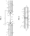
- U indicates a generic electrical energy storage unit belonging to the prior art and comprising at least two planar cells C, each closed inside a respective pouch P, each of which comprises in turn a plurality of positive E+ and negative E- electrode plates stacked alternate to each other and spaced by means of a separator layer (also of a known type and therefore not illustrated).
- Each electrode plate E+, E- comprises a respective electrode tab T (arranged, in this case, on opposite sides of the cell C, i.e. those illustrated in Figure 1 are all electrode tabs T having the same polarity, positive or negative), which extends from a main body B of the cell C (defined precisely by the stack of electrodes and separators).
- the electrode tabs T are initially welded together by means of a weld W' forming a bundle of tabs.
- Such bundle of tabs is then further welded by means of a welding W" to an electrical terminal TR of the cell, having a much greater thickness with respect to each tab T.
- the cells C are then connected in series by contacting the respective terminals TR having a same polarity.
- the distance between the main bodies B of the two cells connected in series corresponds to a distance L', generally in the order of centimeters, in particular greater than 3 cm.
- reference numeral 1 indicates as a whole an electrical energy storage unit that can be installed in a vehicular battery pack (for the mobility of the vehicle) in accordance with a first aspect of the present invention.
- the electrical energy storage unit 1 comprises at least two planar cells C connected to each other in series.
- Each cell C comprises a plurality of electrodes 3 and 4 (for example, negative and positive, respectively).
- each electrode comprises a respective terminal tab 6, which extends protruding from a main body 8 of the cell 2.
- the terminal tabs 6 are made integrally with, or made from, the positive and/or negative electrodes.
- each terminal tab 6 is made integrally with (made from) a current collector (usually coated with active materials) of the positive or negative electrode.
- the current collector and the terminal tab extending therefrom are made of copper for the anode and of aluminum or zinc for the cathode.
- each planar cell 2 has a parallelepiped shape with a very limited thickness with respect to the other dimensions.
- Six faces corresponding two-by-two are thus identified, of which, as illustrated in the non-limiting embodiments of Figures 3 and 4 , two very wide planar faces S', two thin and elongated front faces S" and two lateral thin and elongated faces"' (less with respect to the front faces S"').
- the electrodes 3 and 4 are stacked together in such a way that the tabs 6 with the same polarity (positive or negative - and therefore of the same material) are aligned with each other (vertically).
- the planar cells 2 are arranged in such a way that the tabs 6 having the same polarity (positive or negative - and thus of the same material) of each planar cell 2 are at least partially facing each other.
- the faces S"' (as in the non-limiting embodiment of Figure 3 ) or the faces S" (as in the non-limiting embodiment of Figure 4 ) of two adjacent cells are facing each other (and parallel).
- the planar cells 2 are arranged in such a way that the tabs 6 having the same polarity of two adjacent cells, connected in series, are at least partially superimposed in correspondence with an overlapping area 7. More precisely, the overlapping area 7 between the tabs 6 of two adjacent cells 2 is, with respect to each cell 2, in a distal position of each tab 6, with respect to the main body 8 of the respective cell 2.
- At least one terminal tab 6, belonging to a planar cell 2, and a terminal tab 6, belonging to the adjacent planar cell 2 are directly welded together, in particular preferably by means of a heat welding, so as to connect the two planar cells 2 in series.
- the tabs 6 superimposed in the area 7 clearly having the same polarity.
- the welding is a laser welding, in particular linear (along a direction parallel to the face S", S"' from which the terminal tabs 6 to be welded project) or a spot welding.
- the distance between the main bodies 8 of the two cells 2 connected in series corresponds to a distance L", less than the distance L', preferably in the order of millimeters, in particular less than 25 mm, more precisely less than 10 mm.
- At least one terminal tab 6 of a cell 2 is interposed between two terminal tabs 6 of the other cell 2 and/or vice versa.
- two or more (for example three or four) consecutive aligned tabs having the same polarity and belonging to a planar cell 2 are welded together before being welded with the tabs 6 having the same polarity as the adjacent planar cell 2.
- the terminal tabs 6 having different (opposite) polarities of the same planar cell 2 protrude from opposite sides of the planar cell 2, in particular from the faces S"' of each cell.
- the planar cells 2 connected in series lie on a same plane and on a same longitudinal axis of symmetry.
- the terminal tabs 6 having different (opposite) polarities of a same planar cell 2 protrude from a same side of the planar cell 2, in particular from one of the faces S" of each cell 2.
- the planar cells 2 connected in series lie on the same plane, but not on a same longitudinal axis of symmetry. In particular, they are arranged offset from each other along both directions belonging to the plane on which they lie. More specifically, the cells 2 are equal to each other (in length) and, along a longitudinal direction of the storage unit 1, are offset by half their length. In this way, it is possible to organize the unit 1 with the cells arranged as a coil as illustrated in Figure 4 . In this way, moreover, all the contacts in series are consecutive on the same straight line and it is thus possible to simplify the structure of a safety structure which continuously detects the voltage of each cell.
- the storage unit 1 comprises a single external pouch 5, inside which at least one pair of cells 2 are housed.
- a vehicular battery pack 10 comprising at least one unit 1 according to what previously described.
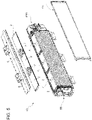
- the battery pack 10 comprises a plurality of levels (layers) of units 1 as illustrated in the non-limiting embodiment of Figure 5 .
- the unit 1 occupies an entire level of the battery pack and also comprises more than two cells connected in series as described. In this way, the advantages of the present invention are maximum.
- a level comprises a plurality of units 1 interconnected in series, according to known techniques.
- the advantages of the present invention are partial, but in any case appreciable.
- the battery pack 10 also comprises a safety system SS and a Battery Management Unit (BMU), in particular arranged, together, on opposite sides of the battery pack 10.
- BMU Battery Management Unit
- the battery pack 10 also comprises a refrigeration system CS, in particular arranged on a wall of the battery pack 10 perpendicular to the levels of the energy storage unit 1 (and on a wall other than those occupied by the system SS and by the BMU).
- a refrigeration system CS in particular arranged on a wall of the battery pack 10 perpendicular to the levels of the energy storage unit 1 (and on a wall other than those occupied by the system SS and by the BMU).
- a method for assemblying planar cells 2 which can be installed in a vehicular battery pack.
- the method is aimed at manufacturing the electrical energy storage units 1.
- the method comprises a step of stacking, with alternating polarity so as to generate the planar cell 2, a plurality of at least three electrodes 3 and 4, each of which comprises a respective terminal tab 6 extending from a main body 8 of the cell 2.
- the electrodes 3 and 4 are stacked in such a way that the tabs 6 having the same polarity are aligned with each other (vertically).
- the method also comprises a step of arranging at least two planar cells 2 in such a way that tabs 6 having the same polarity of each of the two planar cells 2 are at least partially facing and at least partially superimposed in correspondence with an overlapping area 7 of each tab 6, distal with respect to the main body 8.
- the tabs 6 having positive (or negative) polarity of a cell 2 are at least partially superimposed on tabs 6 having negative polarity (or positive polarity, depending on the type of connection in series or in parallel to be made) of the other cell 2.
- the method provides for the further step of welding together, directly, at least one terminal tab 6 belonging to a planar cell 2 and a terminal tab 6 belonging to the adjacent planar cell 2 to which it is connected in series.
- the welding is carried out in correspondence with said overlapping area 7.
- the terminal tabs 6 having the same polarity as a cell 2 and respective terminal tabs 6 having the same polarity of the other cell 2 are welded together so that at least one terminal tab 6 of the first cell 2 is interposed between two terminal tabs 6 of the second cell 2 and/or vice versa.
- the method further comprises a step of pre-welding together one or more terminal tabs 6 having the same polarity and belonging to the same planar cell 6.
- the terminal tabs 6 having the same polarity of a planar cell 2 are welded individually or in pairs with respective terminal tabs 6 having the same polarity of the adjacent cell 2 connected in series.
- the method comprises the further step of enveloping at least the first cell and the second cell inside a same pouch 5.
- the welding step is carried out by means of a welding device provided with a plurality of prongs, as many as the welds between tabs of different cells to be carried out.
- the welding step is carried out by means of a laser welding device.
- the electrical energy storage unit 1 does not comprise intermediate metal terminals (for example the terminal TR) between the tabs 6 of two adjacent cells 2 connected in series.
- the present invention allows optimizing the use of the space inside a battery pack.
- the empty space generally present between two cells connected in series can consequently be filled with active material or can be used to reduce the general volume of the battery pack (given the presence of hundreds of cells, the optimized use of such space produces a considerable effect).
- the present invention allows preventing the slowness of the double laser welding and the high installation and maintenance costs of the double ultrasonic welding, allowing saving time and waste.
- a further advantage of the present invention resides in the fact that the present structure allows reducing or simplifying the number of controls necessary inside the battery pack.
- the method, the unit and the battery pack described above allow limiting the likelihood of waste during the production of a battery pack since the general number of welds to be carried out in the production of a battery pack is almost halved, and therefore also the relative error coefficient.
Landscapes
- Chemical & Material Sciences (AREA)
- Chemical Kinetics & Catalysis (AREA)
- Electrochemistry (AREA)
- General Chemical & Material Sciences (AREA)
- Engineering & Computer Science (AREA)
- Manufacturing & Machinery (AREA)
- Connection Of Batteries Or Terminals (AREA)
- Battery Mounting, Suspending (AREA)
- Secondary Cells (AREA)
Abstract
Description
- This Patent Application claims priority from
Italian Patent Application No. 102020000026593 filed on November 6, 2020 - The present invention relates to the scope of energy storage systems in the automotive sector and in particular it relates to a cell assembly method, to an electrical energy storage unit and to a relative vehicular battery pack.
- Lithium batteries in relation to their high density increasingly allow the implementation of electrics in the automotive sector. Lithium polymers, in particular, currently represent, from a chemical point of view, the state of the art in the production of high-capacity batteries.
- Solutions are known which provide for the interconnection in series and in parallel of different cells (generally, each of 3.7 V) to achieve the desired total voltage and energy density for a vehicular battery pack.
- The battery modules usually available on the market for powering smartphones and tablets (and increasingly widespread also in the automotive sector), consist of planar pouch batteries, which have a very limited thickness compared to the other dimensions. Two very wide opposite faces (through which the heat is dissipated almost entirely) and four thin and elongated sides are identified, in which the positive and negative terminals of the cell are arranged on one or two opposite sides.
- Generally, the aforesaid terminals are used to electrically connect the different cells with each other in series or in parallel. In particular, each cell consists of a plurality of stacked electrode plates with alternating polarity (positive and negative). Each of these electrode plates comprises a tab extending from the rest of the electrode plate and configured to be, by means of a first weld, electrically connected to the other tabs of the same cell extending from plates with the same polarity and, subsequently, by means of a second weld, so as to be connected to the terminal (positive or negative, respectively) of the cell, generally consisting of a metal plate which is thicker and more rigid with respect to the electrode tabs.
- However, the aforesaid welds are generally carried out by means of laser devices (very slow for welding great thicknesses), or ultrasound devices (subject to heavy wear, in particular the sonotrode must be replaced often and the laser device adjusted at each replacement).
- Furthermore, the battery packs obtained by means of the aforesaid production method are still particularly expensive and bulky.
- The object of the present invention, among others, is to provide a cell assembly method, an electrical energy storage unit and a relative vehicular battery pack which are at least partially free from the drawbacks described above and, at the same time, are of simple and cost-effective implementation.
- According to the present invention, a cell assembly method, an electrical energy storage unit and a relative vehicular battery pack are provided as claimed in the appended claims.
- The claims describe preferred embodiments of the present invention forming integral part of the present description.
- The present invention will now be described with reference to the accompanying drawings, which illustrate several non-limiting example embodiments thereof; in particular:
-
Figure 1 is a schematic cross-section view of a portion of an electrical energy storage unit comprising two cells electrically interconnected in series according to the prior art; -
Figure 2 is a schematic cross-section view of a portion of an electrical energy storage unit comprising two cells electrically interconnected in series according to the present invention; -
Figure 3 is a schematic and perspective view of a first embodiment of the present invention; -
Figure 4 is a schematic and perspective view of a second embodiment in accordance with the present invention; and -
Figure 5 is a perspective and schematic view of a vehicular battery pack comprising the storage units ofFigure 3 . - In
Figure 1 , U indicates a generic electrical energy storage unit belonging to the prior art and comprising at least two planar cells C, each closed inside a respective pouch P, each of which comprises in turn a plurality of positive E+ and negative E- electrode plates stacked alternate to each other and spaced by means of a separator layer (also of a known type and therefore not illustrated). Each electrode plate E+, E- comprises a respective electrode tab T (arranged, in this case, on opposite sides of the cell C, i.e. those illustrated inFigure 1 are all electrode tabs T having the same polarity, positive or negative), which extends from a main body B of the cell C (defined precisely by the stack of electrodes and separators). - In each of the cells C illustrated in
Figure 1 , the electrode tabs T are initially welded together by means of a weld W' forming a bundle of tabs. - Such bundle of tabs is then further welded by means of a welding W" to an electrical terminal TR of the cell, having a much greater thickness with respect to each tab T.
- The cells C are then connected in series by contacting the respective terminals TR having a same polarity. As evident from
Figure 1 , the distance between the main bodies B of the two cells connected in series corresponds to a distance L', generally in the order of centimeters, in particular greater than 3 cm. - In
Figure 2 , reference numeral 1 indicates as a whole an electrical energy storage unit that can be installed in a vehicular battery pack (for the mobility of the vehicle) in accordance with a first aspect of the present invention. - The electrical energy storage unit 1 comprises at least two planar cells C connected to each other in series.
- Each cell C comprises a plurality of
electrodes 3 and 4 (for example, negative and positive, respectively). In turn, each electrode comprises arespective terminal tab 6, which extends protruding from a main body 8 of thecell 2. - Advantageously but not necessarily, the
terminal tabs 6 are made integrally with, or made from, the positive and/or negative electrodes. In particular, eachterminal tab 6 is made integrally with (made from) a current collector (usually coated with active materials) of the positive or negative electrode. More particularly, the current collector and the terminal tab extending therefrom are made of copper for the anode and of aluminum or zinc for the cathode. - In particular, each
planar cell 2 has a parallelepiped shape with a very limited thickness with respect to the other dimensions. Six faces corresponding two-by-two are thus identified, of which, as illustrated in the non-limiting embodiments ofFigures 3 and4 , two very wide planar faces S', two thin and elongated front faces S" and two lateral thin and elongated faces"' (less with respect to the front faces S"'). - Advantageously, the
electrodes 3 and 4 are stacked together in such a way that thetabs 6 with the same polarity (positive or negative - and therefore of the same material) are aligned with each other (vertically). In particular, theplanar cells 2 are arranged in such a way that thetabs 6 having the same polarity (positive or negative - and thus of the same material) of eachplanar cell 2 are at least partially facing each other. In other words, the faces S"' (as in the non-limiting embodiment ofFigure 3 ) or the faces S" (as in the non-limiting embodiment ofFigure 4 ) of two adjacent cells are facing each other (and parallel). - Advantageously, and as illustrated in the non-limiting embodiments of
Figures 2 to 5 , theplanar cells 2 are arranged in such a way that thetabs 6 having the same polarity of two adjacent cells, connected in series, are at least partially superimposed in correspondence with anoverlapping area 7. More precisely, theoverlapping area 7 between thetabs 6 of twoadjacent cells 2 is, with respect to eachcell 2, in a distal position of eachtab 6, with respect to the main body 8 of therespective cell 2. - In particular, in correspondence with said overlapping
area 7, at least oneterminal tab 6, belonging to aplanar cell 2, and aterminal tab 6, belonging to the adjacentplanar cell 2, are directly welded together, in particular preferably by means of a heat welding, so as to connect the twoplanar cells 2 in series. Thetabs 6 superimposed in thearea 7 clearly having the same polarity. - In some non-limiting cases, the welding is a laser welding, in particular linear (along a direction parallel to the face S", S"' from which the
terminal tabs 6 to be welded project) or a spot welding. - Advantageously but not necessarily, as illustrated in the non-limiting embodiment of
Figure 2 , the distance between the main bodies 8 of the twocells 2 connected in series corresponds to a distance L", less than the distance L', preferably in the order of millimeters, in particular less than 25 mm, more precisely less than 10 mm. - Preferably, as illustrated in the non-limiting embodiments of
Figures 2 and3 , in the overlapping area (7), at least oneterminal tab 6 of acell 2 is interposed between twoterminal tabs 6 of theother cell 2 and/or vice versa. - According to some non-limiting embodiments, two or more (for example three or four) consecutive aligned tabs having the same polarity and belonging to a
planar cell 2 are welded together before being welded with thetabs 6 having the same polarity as the adjacentplanar cell 2. - According to the non-limiting embodiment of
Figures 3 and5 , theterminal tabs 6 having different (opposite) polarities of the sameplanar cell 2 protrude from opposite sides of theplanar cell 2, in particular from the faces S"' of each cell. In this case, theplanar cells 2 connected in series lie on a same plane and on a same longitudinal axis of symmetry. - In the non-limiting embodiment of
Figure 4 , theterminal tabs 6 having different (opposite) polarities of a sameplanar cell 2 protrude from a same side of theplanar cell 2, in particular from one of the faces S" of eachcell 2. In these cases, theplanar cells 2 connected in series lie on the same plane, but not on a same longitudinal axis of symmetry. In particular, they are arranged offset from each other along both directions belonging to the plane on which they lie. More specifically, thecells 2 are equal to each other (in length) and, along a longitudinal direction of the storage unit 1, are offset by half their length. In this way, it is possible to organize the unit 1 with the cells arranged as a coil as illustrated inFigure 4 . In this way, moreover, all the contacts in series are consecutive on the same straight line and it is thus possible to simplify the structure of a safety structure which continuously detects the voltage of each cell. - Advantageously but not necessarily, the storage unit 1 comprises a single
external pouch 5, inside which at least one pair ofcells 2 are housed. - According to a further aspect of the present invention, a
vehicular battery pack 10 is provided comprising at least one unit 1 according to what previously described. - Advantageously but not necessarily, the
battery pack 10 comprises a plurality of levels (layers) of units 1 as illustrated in the non-limiting embodiment ofFigure 5 . - In some non-limiting cases, such as that illustrated in the upper layer of
Figure 5 , the unit 1 occupies an entire level of the battery pack and also comprises more than two cells connected in series as described. In this way, the advantages of the present invention are maximum. - In other non-limiting cases, such as that illustrated in the second layer (starting from the top), a level comprises a plurality of units 1 interconnected in series, according to known techniques. In this way, the advantages of the present invention are partial, but in any case appreciable.
- Advantageously but not necessarily, the
battery pack 10 also comprises a safety system SS and a Battery Management Unit (BMU), in particular arranged, together, on opposite sides of thebattery pack 10. - Advantageously but not necessarily, the
battery pack 10 also comprises a refrigeration system CS, in particular arranged on a wall of thebattery pack 10 perpendicular to the levels of the energy storage unit 1 (and on a wall other than those occupied by the system SS and by the BMU). - According to a further aspect of the present invention, a method is provided for assemblying
planar cells 2 which can be installed in a vehicular battery pack. In particular, the method is aimed at manufacturing the electrical energy storage units 1. - Advantageously, the method comprises a step of stacking, with alternating polarity so as to generate the
planar cell 2, a plurality of at least threeelectrodes 3 and 4, each of which comprises a respectiveterminal tab 6 extending from a main body 8 of thecell 2. In particular, theelectrodes 3 and 4 are stacked in such a way that thetabs 6 having the same polarity are aligned with each other (vertically). - Advantageously but not necessarily, the method also comprises a step of arranging at least two
planar cells 2 in such a way thattabs 6 having the same polarity of each of the twoplanar cells 2 are at least partially facing and at least partially superimposed in correspondence with an overlappingarea 7 of eachtab 6, distal with respect to the main body 8. In other words, thetabs 6 having positive (or negative) polarity of acell 2 are at least partially superimposed ontabs 6 having negative polarity (or positive polarity, depending on the type of connection in series or in parallel to be made) of theother cell 2. - In particular, the method provides for the further step of welding together, directly, at least one
terminal tab 6 belonging to aplanar cell 2 and aterminal tab 6 belonging to the adjacentplanar cell 2 to which it is connected in series. In detail, the welding is carried out in correspondence with said overlappingarea 7. - Preferably, the
terminal tabs 6 having the same polarity as acell 2 and respectiveterminal tabs 6 having the same polarity of theother cell 2 are welded together so that at least oneterminal tab 6 of thefirst cell 2 is interposed between twoterminal tabs 6 of thesecond cell 2 and/or vice versa. - Advantageously but not necessarily, the method further comprises a step of pre-welding together one or more
terminal tabs 6 having the same polarity and belonging to the sameplanar cell 6. - In some non-limiting cases, the
terminal tabs 6 having the same polarity of aplanar cell 2 are welded individually or in pairs with respectiveterminal tabs 6 having the same polarity of theadjacent cell 2 connected in series. - Advantageously but not necessarily, the method comprises the further step of enveloping at least the first cell and the second cell inside a
same pouch 5. - In some non-limiting cases, the welding step is carried out by means of a welding device provided with a plurality of prongs, as many as the welds between tabs of different cells to be carried out.
- In other non-limiting cases, the welding step is carried out by means of a laser welding device.
- Advantageously but not necessarily, therefore, the electrical energy storage unit 1 does not comprise intermediate metal terminals (for example the terminal TR) between the
tabs 6 of twoadjacent cells 2 connected in series. - In particular, therefore, in the assembly method no intermediate metal terminals are used between the
tabs 6 of twoadjacent cells 2 connected in series. - Although the invention described above makes particular reference to a very precise example embodiment, it is not to be considered limited to such example embodiment, since all the variants, modifications or simplifications covered by the appended claims, such as for example a different type of arrangement, a different type of materials, a different geometric configuration, etc., fall within its scope.
- The method, the unit and the apparatus described above have numerous advantages.
- Firstly, the present invention allows optimizing the use of the space inside a battery pack. In particular, as highlighted by the difference between the length L' and the length L", the empty space generally present between two cells connected in series can consequently be filled with active material or can be used to reduce the general volume of the battery pack (given the presence of hundreds of cells, the optimized use of such space produces a considerable effect).
- Furthermore, the present invention allows preventing the slowness of the double laser welding and the high installation and maintenance costs of the double ultrasonic welding, allowing saving time and waste.
- A further advantage of the present invention resides in the fact that the present structure allows reducing or simplifying the number of controls necessary inside the battery pack.
- Finally, the method, the unit and the battery pack described above allow limiting the likelihood of waste during the production of a battery pack since the general number of welds to be carried out in the production of a battery pack is almost halved, and therefore also the relative error coefficient.
-
- 1
- storage unit
- 2
- cell
- 3
- electrode
- 4
- electrode
- 5
- pouch
- 6
- tab
- 7
- weld
- 8
- cell body
- 10
- battery pack
- U
- storage unit
- C
- cell
- E+
- electrode
- E-
- electrode
- P
- pouch
- T
- tab
- W'
- weld
- W"
- weld
- L'
- cell-to-cell distance
- L"
- cell-to-cell distance
- B
- cell body
- TR
- terminal
- S'
- surface
- S"
- surface
- S"'
- surface
- BMU
- battery management unit
- SS
- safety
- CS
- cooling system
Claims (13)
- A method for assembling cells installable in a vehicle battery pack (10); the method including the steps of:stacking, with alternating polarity so as to generate a planar cell (2), a plurality of at least three electrodes (3, 4), each of which comprises a respective terminal tab (6) extending from a main body (8) of said cell (2); the electrodes (3, 4) being stacked in such a way that the tabs (6) with the same polarity are aligned with each other; wherein the terminal tabs (6) are made integrally with, or made from, the electrodes (3, 4);arranging a first planar cell (2) and a second planar cell (2) in such a way that tabs (6) having the same polarity of the first planar cell (2) and of the second planar cell (2) are, each other, at least partially facing and at least partially superimposed in correspondence with an overlapping area (7) of each tab (6), distal with respect to the main body (8);welding together, directly, at least one terminal tab (6) belonging to the first planar cell (2) and one terminal tab (6) belonging to the second planar cell (2) in correspondence with said overlapping area (7).wherein the terminal tabs (6) having the same polarity as the first cell (2) and respective terminal tabs (6) having the same polarity as the second cell (2) are welded together so that at least one terminal tab (6) of the first cell (2) is interposed between two terminal tabs (6) of the second cell (2) and/or vice versa.
- The method according to claim 1, and comprising a step of pre-welding together more terminal tabs (6) having the same polarity and belonging to the same first or second cell (2).
- The method according to claim 1, wherein the terminal tabs (6) of the first (2) cell and having the same polarity are welded individually or in pairs with respective terminal tabs (6) having the same polarity as the second cell (2).
- The method according to any one of the preceding claims, and comprising the further step of enveloping at least the first cell (2) and the second cell (2) inside the same pouch (5) or casing.
- The method according to any one of the preceding claims, wherein the welding step is carried out by means of a welding device provided with a plurality of prongs, as many as the welds between tabs (6) of different cells to be carried out.
- Method according to any one of the preceding claims, wherein intermediate metal terminals are not used between the tabs (6) belonging to the first planar cell (2) and the tabs (6) belonging to the second planar cell (2).
- An electric energy storage unit (1) installable in a vehicle battery pack (10); the unit (1) comprising at least a first planar cell (2) and a second planar cell (2) each comprising a plurality of at least three electrodes (3, 4), each of which in turn comprises a respective terminal tab (6) extending from a main body (8) of the respective cell (2); the electrodes (3, 4) being stacked in such a way that the tabs (6) with the same polarity are aligned with each other; wherein the terminal tabs (6) are made integrally with, or made from, the electrodes (3, 4); wherein the first planar cell (2) and the second planar cell (2) are arranged so that the tabs (6) having the same polarity of the first planar cell (2) and of the second planar cell (2) at least partially face each other;the storage unit (1) being characterized in that the first planar cell (2) and the second planar cell (2) are arranged so that the tabs (6) having the same polarity of the first planar cell (2) and of the second planar cell (2) are at least partially superimposed in correspondence with an overlapping area (7) of each tab (6), distal with respect to the main body (8); wherein, in correspondence with said overlapping area (7), at least one terminal tab (6) belonging to the first planar cell (2) and one terminal tab (6) belonging to the second planar cell (2) are directly welded together;wherein, in the overlapping area (7), at least one terminal tab (6) of the first cell (2) is interposed between two terminal tabs (6) of the second cell (2) and/or vice versa.
- The unit (1) according to claim 7, wherein adjacent tabs (6) having the same polarity and belonging to the first planar cell (2) are welded together before being welded with the tabs (6) having the same polarity as the second planar cell (2).
- The unit (1) according to any one of claims 7 or 8, wherein the terminal tabs (6) having different polarity protrude from opposite sides of the respective planar cell (2); wherein the first planar cell (2) and the second planar cell (2) lie on the same plane and on the same longitudinal axis of symmetry.
- The unit (1) according to any one of claims 7 or 8, wherein the terminal tabs (6) having different polarity protrude from the same side of the respective planar cell (2); wherein the first planar cell (2) and the second planar cell (2) lie on the same plane, but not on the same longitudinal axis of symmetry.
- The unit (1) according to claim 10, wherein the cells are arranged offset from each other along both directions belonging to the plane on which they lie.
- The unit (1) according to claim 11, wherein the cells are equal to each other in length and, along a longitudinal direction of the storage unit (1), are offset by half their length.
- A vehicular battery pack (10) comprising at least one unit (1) according to any one of claims 7 to 12.
Applications Claiming Priority (1)
| Application Number | Priority Date | Filing Date | Title |
|---|---|---|---|
| IT102020000026593A IT202000026593A1 (en) | 2020-11-06 | 2020-11-06 | ASSEMBLY METHOD OF CELLS, STORAGE UNITS AND RELATIVE VEHICLE BATTERY PACK |
Publications (1)
| Publication Number | Publication Date |
|---|---|
| EP3996181A1 true EP3996181A1 (en) | 2022-05-11 |
Family
ID=74347550
Family Applications (1)
| Application Number | Title | Priority Date | Filing Date |
|---|---|---|---|
| EP21206797.9A Pending EP3996181A1 (en) | 2020-11-06 | 2021-11-05 | Cell assembly method, storage unit and relative vehicular battery pack |
Country Status (5)
| Country | Link |
|---|---|
| US (1) | US20220149486A1 (en) |
| EP (1) | EP3996181A1 (en) |
| JP (1) | JP7840660B2 (en) |
| CN (1) | CN114447526A (en) |
| IT (1) | IT202000026593A1 (en) |
Families Citing this family (1)
| Publication number | Priority date | Publication date | Assignee | Title |
|---|---|---|---|---|
| CN115966850A (en) * | 2022-12-30 | 2023-04-14 | 蜂巢能源科技股份有限公司 | Arrangement method of a pouch battery module |
Citations (3)
| Publication number | Priority date | Publication date | Assignee | Title |
|---|---|---|---|---|
| WO2006109610A1 (en) * | 2005-04-05 | 2006-10-19 | Nec Corporation | Production method for electric device assembly and electric device assembly |
| KR20080074239A (en) * | 2007-02-08 | 2008-08-13 | 주식회사 엘지화학 | High capacity battery cell with excellent lifespan characteristics and safety |
| US20130323559A1 (en) * | 2006-06-05 | 2013-12-05 | Lg Chem, Ltd. | High capacity battery cell employed with two or more unit cells |
Family Cites Families (10)
| Publication number | Priority date | Publication date | Assignee | Title |
|---|---|---|---|---|
| JP4461686B2 (en) * | 2003-02-13 | 2010-05-12 | トヨタ自動車株式会社 | Secondary battery, manufacturing apparatus and manufacturing method thereof |
| JP2006196428A (en) * | 2004-05-31 | 2006-07-27 | Nissan Motor Co Ltd | Battery pack and manufacturing method thereof |
| US20070134551A1 (en) * | 2005-12-14 | 2007-06-14 | Avestor Limited Partnership | Electrochemical battery and method for making same |
| US8460817B2 (en) * | 2009-05-06 | 2013-06-11 | GM Global Technology Operations LLC | Method for manufacture of battery pouch terminals |
| EP2765631B1 (en) * | 2011-10-06 | 2016-07-20 | Toyota Jidosha Kabushiki Kaisha | Assembled battery and production method for assembled battery |
| JP6891930B2 (en) * | 2015-03-30 | 2021-06-18 | 三洋電機株式会社 | Square secondary battery and assembled battery using it |
| EP4668405A3 (en) * | 2015-06-18 | 2026-03-25 | 24M Technologies, Inc. | Single pouch battery cells and methods of manufacture |
| JP2017212178A (en) * | 2016-05-27 | 2017-11-30 | 株式会社豊田自動織機 | Battery module |
| US11038192B2 (en) * | 2017-06-02 | 2021-06-15 | GM Global Technology Operations LLC | Configurations for power module having an integrated flexible circuit assembly |
| KR102410862B1 (en) * | 2017-11-10 | 2022-06-21 | 에스케이온 주식회사 | Battery module |
-
2020
- 2020-11-06 IT IT102020000026593A patent/IT202000026593A1/en unknown
-
2021
- 2021-11-04 CN CN202111301233.1A patent/CN114447526A/en active Pending
- 2021-11-05 JP JP2021181445A patent/JP7840660B2/en active Active
- 2021-11-05 US US17/519,702 patent/US20220149486A1/en not_active Abandoned
- 2021-11-05 EP EP21206797.9A patent/EP3996181A1/en active Pending
Patent Citations (3)
| Publication number | Priority date | Publication date | Assignee | Title |
|---|---|---|---|---|
| WO2006109610A1 (en) * | 2005-04-05 | 2006-10-19 | Nec Corporation | Production method for electric device assembly and electric device assembly |
| US20130323559A1 (en) * | 2006-06-05 | 2013-12-05 | Lg Chem, Ltd. | High capacity battery cell employed with two or more unit cells |
| KR20080074239A (en) * | 2007-02-08 | 2008-08-13 | 주식회사 엘지화학 | High capacity battery cell with excellent lifespan characteristics and safety |
Also Published As
| Publication number | Publication date |
|---|---|
| US20220149486A1 (en) | 2022-05-12 |
| CN114447526A (en) | 2022-05-06 |
| JP7840660B2 (en) | 2026-04-06 |
| JP2022075652A (en) | 2022-05-18 |
| IT202000026593A1 (en) | 2022-05-06 |
Similar Documents
| Publication | Publication Date | Title |
|---|---|---|
| EP2535962B1 (en) | Battery module having enhanced welding reliability and medium or large battery pack including same | |
| US20250025957A1 (en) | Electrode Having Improved Electrode Tab Welding Characteristics and Secondary Battery Comprising the Same | |
| EP1812982B1 (en) | Secondary battery pack having configuration of alternative orientation | |
| KR100590006B1 (en) | Secondary Battery and Electrode Assembly Used in the Same | |
| EP2779269B1 (en) | Battery cell having a novel structure | |
| US11777178B2 (en) | Battery module, vehicle provided with same, and bus bar | |
| EP3676888B1 (en) | Lead tab for a battery terminal | |
| JP2015187910A (en) | Battery pack and electric vehicle including the same and power storage device | |
| EP3561906B1 (en) | Battery module | |
| EP2615666A2 (en) | Battery pack with high output and large capacity | |
| CN113614996B (en) | Power supply device, electric vehicle equipped with power supply device, and power storage device | |
| KR20180126534A (en) | Multi-joint battery module | |
| US12183952B2 (en) | Battery pack with enhanced structure for preventing short circuit and shock | |
| KR20110005595A (en) | Battery module | |
| KR20180081604A (en) | Wall-through collector for pouch cells | |
| CN113646956A (en) | Power supply device, electric vehicle using the same, and power storage device, fastening member for power supply device, method for manufacturing power supply device, and method for producing fastening member for power supply device | |
| EP3996181A1 (en) | Cell assembly method, storage unit and relative vehicular battery pack | |
| US20200161626A1 (en) | Laminar Current Collector | |
| EP4362206B1 (en) | Battery module and battery pack and vehicle including the same | |
| JP2024021232A (en) | Battery modules and batteries | |
| KR20260027785A (en) | Secondary battery | |
| KR20260027765A (en) | Secondary battery, and battery module, battery pack and vehicle comprising the same |
Legal Events
| Date | Code | Title | Description |
|---|---|---|---|
| PUAI | Public reference made under article 153(3) epc to a published international application that has entered the european phase |
Free format text: ORIGINAL CODE: 0009012 |
|
| STAA | Information on the status of an ep patent application or granted ep patent |
Free format text: STATUS: THE APPLICATION HAS BEEN PUBLISHED |
|
| AK | Designated contracting states |
Kind code of ref document: A1 Designated state(s): AL AT BE BG CH CY CZ DE DK EE ES FI FR GB GR HR HU IE IS IT LI LT LU LV MC MK MT NL NO PL PT RO RS SE SI SK SM TR |
|
| STAA | Information on the status of an ep patent application or granted ep patent |
Free format text: STATUS: REQUEST FOR EXAMINATION WAS MADE |
|
| 17P | Request for examination filed |
Effective date: 20221111 |
|
| P01 | Opt-out of the competence of the unified patent court (upc) registered |
Effective date: 20230525 |
|
| STAA | Information on the status of an ep patent application or granted ep patent |
Free format text: STATUS: EXAMINATION IS IN PROGRESS |
|
| 17Q | First examination report despatched |
Effective date: 20241002 |