EP3995925A1 - Autonomous mobile robot, transporter, autonomous mobile robot control method, and transporter control method - Google Patents
Autonomous mobile robot, transporter, autonomous mobile robot control method, and transporter control method Download PDFInfo
- Publication number
- EP3995925A1 EP3995925A1 EP21206670.8A EP21206670A EP3995925A1 EP 3995925 A1 EP3995925 A1 EP 3995925A1 EP 21206670 A EP21206670 A EP 21206670A EP 3995925 A1 EP3995925 A1 EP 3995925A1
- Authority
- EP
- European Patent Office
- Prior art keywords
- mobile robot
- autonomous mobile
- data
- accordance
- detector
- Prior art date
- Legal status (The legal status is an assumption and is not a legal conclusion. Google has not performed a legal analysis and makes no representation as to the accuracy of the status listed.)
- Granted
Links
Images




Classifications
-
- G—PHYSICS
- G05—CONTROLLING; REGULATING
- G05D—SYSTEMS FOR CONTROLLING OR REGULATING NON-ELECTRIC VARIABLES
- G05D1/00—Control of position, course, altitude or attitude of land, water, air or space vehicles, e.g. using automatic pilots
- G05D1/02—Control of position or course in two dimensions
- G05D1/021—Control of position or course in two dimensions specially adapted to land vehicles
- G05D1/0231—Control of position or course in two dimensions specially adapted to land vehicles using optical position detecting means
- G05D1/0238—Control of position or course in two dimensions specially adapted to land vehicles using optical position detecting means using obstacle or wall sensors
- G05D1/024—Control of position or course in two dimensions specially adapted to land vehicles using optical position detecting means using obstacle or wall sensors in combination with a laser
-
- B—PERFORMING OPERATIONS; TRANSPORTING
- B66—HOISTING; LIFTING; HAULING
- B66F—HOISTING, LIFTING, HAULING OR PUSHING, NOT OTHERWISE PROVIDED FOR, e.g. DEVICES WHICH APPLY A LIFTING OR PUSHING FORCE DIRECTLY TO THE SURFACE OF A LOAD
- B66F9/00—Devices for lifting or lowering bulky or heavy goods for loading or unloading purposes
- B66F9/06—Devices for lifting or lowering bulky or heavy goods for loading or unloading purposes movable, with their loads, on wheels or the like, e.g. fork-lift trucks
- B66F9/063—Automatically guided
-
- B—PERFORMING OPERATIONS; TRANSPORTING
- B66—HOISTING; LIFTING; HAULING
- B66F—HOISTING, LIFTING, HAULING OR PUSHING, NOT OTHERWISE PROVIDED FOR, e.g. DEVICES WHICH APPLY A LIFTING OR PUSHING FORCE DIRECTLY TO THE SURFACE OF A LOAD
- B66F9/00—Devices for lifting or lowering bulky or heavy goods for loading or unloading purposes
- B66F9/06—Devices for lifting or lowering bulky or heavy goods for loading or unloading purposes movable, with their loads, on wheels or the like, e.g. fork-lift trucks
- B66F9/075—Constructional features or details
- B66F9/0755—Position control; Position detectors
-
- G—PHYSICS
- G05—CONTROLLING; REGULATING
- G05D—SYSTEMS FOR CONTROLLING OR REGULATING NON-ELECTRIC VARIABLES
- G05D1/00—Control of position, course, altitude or attitude of land, water, air or space vehicles, e.g. using automatic pilots
- G05D1/02—Control of position or course in two dimensions
- G05D1/021—Control of position or course in two dimensions specially adapted to land vehicles
- G05D1/0212—Control of position or course in two dimensions specially adapted to land vehicles with means for defining a desired trajectory
- G05D1/0219—Control of position or course in two dimensions specially adapted to land vehicles with means for defining a desired trajectory ensuring the processing of the whole working surface
-
- G—PHYSICS
- G05—CONTROLLING; REGULATING
- G05D—SYSTEMS FOR CONTROLLING OR REGULATING NON-ELECTRIC VARIABLES
- G05D1/00—Control of position, course, altitude or attitude of land, water, air or space vehicles, e.g. using automatic pilots
- G05D1/02—Control of position or course in two dimensions
- G05D1/021—Control of position or course in two dimensions specially adapted to land vehicles
- G05D1/0212—Control of position or course in two dimensions specially adapted to land vehicles with means for defining a desired trajectory
- G05D1/0225—Control of position or course in two dimensions specially adapted to land vehicles with means for defining a desired trajectory involving docking at a fixed facility, e.g. base station or loading bay
-
- G—PHYSICS
- G05—CONTROLLING; REGULATING
- G05D—SYSTEMS FOR CONTROLLING OR REGULATING NON-ELECTRIC VARIABLES
- G05D1/00—Control of position, course, altitude or attitude of land, water, air or space vehicles, e.g. using automatic pilots
- G05D1/02—Control of position or course in two dimensions
- G05D1/021—Control of position or course in two dimensions specially adapted to land vehicles
- G05D1/0231—Control of position or course in two dimensions specially adapted to land vehicles using optical position detecting means
- G05D1/0246—Control of position or course in two dimensions specially adapted to land vehicles using optical position detecting means using a video camera in combination with image processing means
- G05D1/0251—Control of position or course in two dimensions specially adapted to land vehicles using optical position detecting means using a video camera in combination with image processing means extracting 3D information from a plurality of images taken from different locations, e.g. stereo vision
-
- G—PHYSICS
- G05—CONTROLLING; REGULATING
- G05D—SYSTEMS FOR CONTROLLING OR REGULATING NON-ELECTRIC VARIABLES
- G05D1/00—Control of position, course, altitude or attitude of land, water, air or space vehicles, e.g. using automatic pilots
- G05D1/02—Control of position or course in two dimensions
- G05D1/021—Control of position or course in two dimensions specially adapted to land vehicles
- G05D1/0268—Control of position or course in two dimensions specially adapted to land vehicles using internal positioning means
- G05D1/0274—Control of position or course in two dimensions specially adapted to land vehicles using internal positioning means using mapping information stored in a memory device
-
- G—PHYSICS
- G05—CONTROLLING; REGULATING
- G05D—SYSTEMS FOR CONTROLLING OR REGULATING NON-ELECTRIC VARIABLES
- G05D1/00—Control of position, course, altitude or attitude of land, water, air or space vehicles, e.g. using automatic pilots
- G05D1/60—Intended control result
- G05D1/646—Following a predefined trajectory, e.g. a line marked on the floor or a flight path
-
- G—PHYSICS
- G05—CONTROLLING; REGULATING
- G05D—SYSTEMS FOR CONTROLLING OR REGULATING NON-ELECTRIC VARIABLES
- G05D1/00—Control of position, course, altitude or attitude of land, water, air or space vehicles, e.g. using automatic pilots
- G05D1/60—Intended control result
- G05D1/656—Interaction with payloads or external entities
- G05D1/667—Delivering or retrieving payloads
-
- G—PHYSICS
- G06—COMPUTING OR CALCULATING; COUNTING
- G06V—IMAGE OR VIDEO RECOGNITION OR UNDERSTANDING
- G06V20/00—Scenes; Scene-specific elements
- G06V20/50—Context or environment of the image
- G06V20/56—Context or environment of the image exterior to a vehicle by using sensors mounted on the vehicle
- G06V20/58—Recognition of moving objects or obstacles, e.g. vehicles or pedestrians; Recognition of traffic objects, e.g. traffic signs, traffic lights or roads
-
- G—PHYSICS
- G05—CONTROLLING; REGULATING
- G05D—SYSTEMS FOR CONTROLLING OR REGULATING NON-ELECTRIC VARIABLES
- G05D2107/00—Specific environments of the controlled vehicles
- G05D2107/70—Industrial sites, e.g. warehouses or factories
-
- G—PHYSICS
- G05—CONTROLLING; REGULATING
- G05D—SYSTEMS FOR CONTROLLING OR REGULATING NON-ELECTRIC VARIABLES
- G05D2111/00—Details of signals used for control of position, course, altitude or attitude of land, water, air or space vehicles
- G05D2111/10—Optical signals
- G05D2111/17—Coherent light, e.g. laser signals
Definitions
- Embodiments described herein relate generally to an autonomous mobile robot, a transporter, an autonomous mobile robot control method, and a transporter control method.
- an AGV Automatic Guided Vehicle
- the AGV is configured to calculate a self-location by measuring a direction and a distance with respect to a reflector provided on a wall using a laser range finder, and automatically travels in accordance with the calculation result.
- SLAM Simultaneous Localization and Mapping
- an autonomous mobile robot has a driver, a first detector, a second detector, a localization estimation part, a route-generating part, and a control part.
- the autonomous mobile robot is autonomously movable.
- the driver is configured to cause the autonomous mobile robot to move.
- the first detector is provided at a position higher than a position in height of an object present around the autonomous mobile robot.
- the first detector is configured to obtain first data by scanning the object at a first region around the autonomous mobile robot.
- the second detector is configured to obtain second data by scanning the object at a second region around the autonomous mobile robot.
- the localization estimation part is configured to calculate an estimated position of the autonomous mobile robot in a predetermined region in accordance with the first data.
- the route-generating part is configured to calculate a position of the object present around the autonomous mobile robot in accordance with the second data.
- the route-generating part is configured to calculate a route to a target position in accordance with the estimated position and the position of the object.
- the control part is configured to control the driver in accordance with the route.
- the control part is configured to cause the autonomous mobile robot to travel to the target position.
- the autonomous mobile robot is applicable to a transporter.
- the transporter is configured to transport a transport object.
- the transporter transfers the transport object in which packages, commercial products, or the like are loaded in a distribution center or a back yard of a shop.
- a transporter 1 (referred to as a locomotion robot or an autonomous mobile robot) transports a transport object D.
- the transport object D is, for example, a roll box pallet.
- a travel direction P in which the transport object D moves is determined.
- the transport object D has a lower surface and an upper surface.
- the transport object D includes, for example, a bottom plate D1 formed in a rectangular plate shape, a plurality of wheels C (leg) provided on the lower surface of the bottom plate D1, and a frame D2 provided on the upper surface of the bottom plate D1.
- a transport object (not shown in the drawings) is to be mounted on the upper surface side of the bottom plate D1.
- the frame D2 is provided so as to surround the transport object on the upper surface side of the bottom plate D1.
- the frame D2 has four faces.
- the frame D2 is formed so as to surround a circumference of the transport object, for example, on four surfaces of the transport object above the bottom plate D1. At least one of the four faces of the frame D2 is an openable and closable door.
- the frame D2 may have a configuration in which one face of the frame D2 is opened without providing a door.
- the wheels C are disposed at four corners on the lower surface side of the bottom plate D1.
- the wheels C cause the bottom plate D1 to move with respect to the floor surface E.
- the wheels C are two pairs of wheels provided on the lower surface side of the bottom plate D1.
- the two pairs of the wheels are spaced at a predetermined distance in the travel direction P.
- the transporter 1 includes, for example, a transfer carriage 2 that transfers the transport object D and a plurality of detectors used for sensing provided at the transfer carriage 2.
- the detectors includes a first detector 10, a second detector 11, and a third detector 12.
- the transfer carriage 2 includes, for example, a load base 3 having an upper surface.
- the bottom plate D1 is to be mounted on the upper surface of the load base 3.
- the load base 3 has a lower surface.
- a plurality of wheels 6 are provided on the lower surface of load base 3.
- the wheels 6 are driven by a driver 14 (refer to FIG. 2 ) as described hereinbelow. As the wheels 6 are driven, the load base 3 can travel on the floor surface E.
- the wheels 6 are driven by a commonly-used two-wheel independent drive system using the driver 14 described below. As the wheels 6 are driven, the transporter 1 travels. The direction of movement of the transporter 1 is controlled by a control part 110 as described hereinbelow.
- the wheels 6 may be driven by use of a steering wheel or a particular kind of wheel so as to omnidirectionally travel.
- the height of the load base 3 is determined such that the load base 3 can enter into a region between the bottom plate D1 of the transport object D and the floor surface E.
- a lifter 4 is provided on the upper surface side of the load base 3.
- the height of the lifter 4 is adjustable.
- the lifter 4 is controlled by the control part 110 described later.
- the load base 3 transfers the transport object D in a state in which the transport object D is lifted up by the lifter 4.
- the load base 3 may transfer the transport object D while generating a friction between the lower surface side of the bottom plate D1 and an upper surface side of the lifter 4 without lifting up the transport object D.
- the transfer carriage 2 may transfer the transport object D by traction while hooking the transport object D using a pin or the like without providing the load base 3 and the lifter 4.
- a housing 7 is provided at, for example, a front side in the travel direction P on the load base 3 (refer to FIG. 1 ).
- a controller 100 described later is housed in the housing 7.
- the housing 7 is formed in a rectangular parallelepiped shape.
- the housing 7 is provided upright from the upper surface side of the load base 3.
- a rotating light K is provided at an upper surface side of the housing 7. The rotating light K informs operators around the transporter 1 that the transporter 1 is approaching.
- the rotating light K has a light source, for example, that rotates to cause the operators to visually recognize the transporter 1, and the rotating light K attracts the attention of the operators to the approaching transfer carriage 2.
- a support member 8 is provided at an upper surface side of the housing 7.
- the support member 8 is formed in a rod shape.
- the support member 8 is configured to be provided upright.
- the support member 8 is formed in, for example, a frame shape when viewed from a direction along the travel direction P.
- the support member 8 has a configuration in which two rod members are provided upright, and another rod member is further connected to the two rod members so as to intersect therewith.
- the support member 8 may be formed so as to have a reinforced truss structure that increases bending rigidity in a front-back direction for preventing vibration or may be formed so as to have other structures.
- the first detector 10 and the rotating light K are provided at an upper end of the support member 8.
- the first detector 10 detects an object around the transporter 1.
- the first detector 10 is, for example, an LRF (Laser Range Finder).
- the first detector 10 scans the object with a laser beam, receives reflection light reflected from the object, and measures a distance to the surface of the object in accordance with a phase difference of the reflection light or a differential arrival time.
- the first detector 10 obtains first data by scanning the object at a first region around the transfer carriage 2.
- the first detector 10 scans the object in a predetermined angle range, for example, in a planar direction around the first detector 10 and obtains the first data associated with a distance to the surface of the object around the first detector 10 at a plurality of points.
- the first data is used to generate a localization-and-estimation map of the transfer carriage 2 as described hereinbelow.
- a degree of accuracy of estimating the localization becomes degraded.
- a distribution center a back yard of a shop, or the like, a human is present around the transporter 1, other roll box pallets are placed, and the ambient environment of the transporter 1 varies from hour to hour.
- commercial products are often on a store shelf or the like near the floor surface, and the number of products temporally varies.
- the ambient environment includes an environment inherence object and a surrounding existence object.
- the environment inherence object means an inherence object, for example, a circumference wall, fixed equipment, a pillar, or the like. It is assumed that the position or the shape of the environment inherence object is not changed when the transfer carriage 2 is driven.
- the surrounding existence object is an object other than the environment inherence object of the ambient environment. It is assumed that the position or the shape of the surrounding existence object is changed when the transfer carriage 2 is driven.
- the surrounding existence object is, for example, an object present around the transfer carriage 2 (a human, a transport object such as transfer carriage, roll box pallet, or the like).
- the surrounding existence object is often located closer to the moving transfer carriage 2 than the environment inherence object. Furthermore, regarding the ambient environment, the environment inherence object such as the circumference wall, the fixed equipment, the pillar, or the like is not changed. Consequently, the first detector 10 is attached to a position in height which is assumed in advance such that the surrounding existence object of the ambient environment such as a transfer object, a movable object, or the like is not present. Particularly, the first detector 10 is provided at a position in height of the object (surrounding existence object) present around the transfer carriage 2.
- the first detector 10 be attached to a position higher than that of the other transport object (roll box pallet) or the moving obstacle such as a human, which causes the ambient environment to be varied.
- the first detector 10 is provided at a position, for example, higher than or equal to 1.8 meters, which is a position higher than a body height of a common person. Heights of roll box pallets used in a distribution center or a back yard of a shop are different from each other.
- the first detector 10 is provided such that the height of the first detector 10 is manually adjustable so as to be higher than the position in height of an object, for example, a moving obstacle or the like present around the first detector.
- an adjuster (not shown in the drawings) may be provided at the first detector 10. The adjuster can automatically adjust the position of the first detector 10 to be higher than the position in height of an object, for example, a moving obstacle or the like present around the first detector.
- the second detector 11 that obtains second data by scanning the object is provided at a second region around the transfer carriage 2 at the forward side of the housing 7 in the travel direction P.
- the second detector 11 is, for example, an LRF.
- the second detector 11 scans the object with a laser beam, receives reflection light reflected from the object, and measures a distance to the surface of the object in accordance with a phase difference of the reflection light or a differential arrival time.
- the second detector 11 scans the object in a predetermined angle range, for example, in a planar direction in front of the second detector 11 and obtains the second data associated with a distance to the surface of the object in front of the second detector 11 at a plurality of points.
- the second detector 11 detects, for example, a transfer object or a movable object around the second detector 11.
- the movable object means, for example, a shelf that is optionally changeable in position, the other transport object D that is being temporarily halted, a transfer object such as a human, or the like.
- the third detector 12 is provided at the back side of the load base 3 in the travel direction P.
- the third detector 12 obtains third data associated with positions of the wheels 6 (leg) provided at the lower portion of the transport object D.
- the third detector 12 is, for example, an LRF.
- the third detector 12 is attached to a lower position in order to detect the wheels 6.
- the third detector 12 scans the wheels 6 with a laser beam, receives reflection light reflected from the wheels 6, and measures a distance to the surface of the wheel 6 in accordance with a phase difference of the reflection light or a differential arrival time.
- the third detector 12 scans the object in a predetermined angle range, for example, in a planar direction of the laser scanning direction and obtains the third data associated with a distance to the surface of the wheel 6 in front of the third detector 12 at a plurality of points. As described below, the positions of the wheels 6 supporting the transport object D are obtained in accordance with the third data detected by the third detector 12, and the load base 3 can be inserted between the pair of the wheels 6 facing each other in the travel direction P.
- a depth camera capable of obtaining distance information as well as the LRF may be used as the third detector 12.
- the third detector 12 may be configured of a plurality of infrared distance sensors.
- the controller 100 is housed in, for example, the housing 7.
- the controller 100 may be a device that may be configured by a server device and controls the transfer carriage 2 via a network.
- the transfer carriage 2 includes a power-supply device (not shown in the drawings) as well as the shown configuration.
- the server device is a device capable of communicating with a plurality of transfer carriages 2 and is configured to concentratedly control the transfer carriages 2.
- the server device includes a communicator configured to communicate with the transfer carriages 2, a processor such as CPU (Central Processing Unit), a storage, or the like.
- the controller 100 includes, for example, a storage 102, a map-generating part 104, a localization estimation part 106, a route-generating part 108, a control part 110, and a docking control part 112.
- the storage 102 stores various data.
- the map-generating part 104 generates a map for estimating a position of the transporter 1.
- the localization estimation part 106 calculates an estimated position of the transfer carriage 2 in accordance with the first data obtained by the first detector 10 and the map.
- the route-generating part 108 calculates a route to a target position of the transporter 1 in accordance with the second data obtained by the second detector 11 and the estimated position.
- the control part 110 controls the driver 14 in accordance with the third data formed by the route and the third detector 12 and causes the transfer carriage to travel to the target position.
- the docking control part 112 controls docking with respect to the transport object D.
- a processor such as CPU (Central Processing Unit) executes program (computer program, software) stored in the storage 102
- program computer program, software
- a part or all of functional parts of the map-generating part 104, the localization estimation part 106, the route-generating part 108, the control part 110, and the docking control part 112 is operated.
- a part or all of the functions of the aforementioned constituent parts may be achieved by hardware (circuit part, including circuitry) such as LSI (Large Scale Integration Circuit), ASIC (Application Specific Integrated Circuit), FPGA (Field Programmable Gate Array), GPU (Graphics Processing Unit), or the like, or may be achieved by cooperation of software and hardware.
- LSI Large Scale Integration Circuit
- ASIC Application Specific Integrated Circuit
- FPGA Field Programmable Gate Array
- GPU Graphics Processing Unit
- the program may be stored in advance in a storage device such as a HDD (hard disk drive), a flash memory, or the like.
- the program may be stored in a removable recording medium such as a DVD, a CD-ROM, or the like. By loading the recording medium to a drive device, the program may be installed in the drive device.
- a localization-and-estimation map is generated by SLAM in order to estimate the localization of the transporter 1.
- the environment of generating the map is the same as the environment of movement of the locomotion robot.
- the localization-and-estimation map is generated by causing the transporter 1 to travel by a manual operation.
- the transporter 1 travels in a predetermined region such as a business place, that is an object in which the transporter 1 travels
- the first data generated by the first detector 10 is stored in the storage 102.
- the storage 102 is realized by a recording medium, for example, a RAM (Random Access Memory), a ROM (Read Only Memory), a HDD, a flash memory, or the like.
- the map-generating part 104 uses, for example, the first data, calculates a two-dimensional shape associated with the environment inherence object such as the circumference wall, the fixed equipment, or the like, and generates the localization-and-estimation map.
- the map-generating part 104 may generate the localization-and-estimation map in accordance with the first data as well as the localization-and-estimation map in accordance with the second data.
- the map-generating part 104 may separately generate the localization-and-estimation map at the horizontal plane at a measured height of the first detector 10 in accordance with construction drawing data.
- the localization-and-estimation map generated by the map-generating part 104 is stored in the storage 102.
- the localization estimation part 106 calculates two-dimensional distance information associated with the environment inherence object such as the wall around the transporter 1 (the transfer carriage 2), the fixed equipment, or the like in accordance with the first data obtained by the first detector 10.
- the localization estimation part 106 compares the calculated two-dimensional distance information to the localization-and-estimation map and extracts the predetermined region coincident with the two-dimensional distance information from the localization-and-estimation map.
- the localization estimation part 106 calculates a relative angle (posture) and a relative position with respect to a planar direction of the transporter 1 in the predetermined region extracted in accordance with the extracted predetermined region and the calculated two-dimensional distance information.
- the localization estimation part 106 calculates an estimated position on the two-dimensional coordinate system of the transporter 1 in the localization-and-estimation map in accordance with the calculation result.
- the route-generating part 108 calculates the shape of the obstacle present around the transporter 1 in accordance with the second data obtained by the second detector 11.
- the route-generating part 108 compares the two-dimensional distance information associated with the environment inherence object such as the wall around the transporter 1, the fixed equipment, or the like in the extracted predetermined region and the shape of the object present around the transporter 1 in accordance with the second data, and extracts the obstacle present around the transporter 1.
- the route-generating part 108 generates a route from the estimated position of the transporter 1 to the target position.
- the route-generating part 108 generates a route that avoids the extracted obstacle.
- the route-generating part 108 updates real-time information associated with the obstacles such as the number, the position, the direction of movement, the speed, the size, or the like at a predetermined timing, and updates route that avoids the obstacle.
- the predetermined timing is adjusted in accordance with the movement speed of the transporter 1.
- the route-generating part 108 may not only generate a route that avoids the obstacle in accordance with a moving state of the obstacle but also generate a route that avoids the obstacle by adjusting the speed of the transfer carriage 2
- the control part 110 controls the driver 14 in accordance with the route generated by the route-generating part 108 and causes the transfer carriage 2 to travel along the route.
- the driver 14 independently controls the wheels 6 provided at right and left of the transfer carriage 2, and controls the speed and the direction of the transfer carriage 2.
- the control part 110 controls the driver 14 and thereby controls the transfer carriage 2 so as to be stopped or so as to avoid the obstacle in the case in which the obstacle comes close at a distance to be less than or equal to a previously-set reference.
- the control part 110 controls deceleration of the driver 14 and the direction of the transfer carriage so as to prevent load collapse.
- the control part 110 may cause the rotating light K to change a light emission pattern thereof and to light up in the case in which a human comes close at a distance to be less than or equal to a previously-set reference. As well as the rotating light K, the control part 110 may cause a speaker (not shown in the drawings) to emit sound and thereby notify the human. In the case in which the obstacle is the other transporter 1, the control part 110 may communicate with the other transporter 1 and adjust the relative distance with respect to the other transporter 1. The control part 110 may communicate with a control apparatus (not shown in the drawings) via a network and adjust the relative position with respect to the other transporter 1.
- the docking control part 112 recognizes arrangement of the wheels C of the transport object D in accordance with the third data obtained by the third detector.
- the docking control part 112 recognizes a space between the wheels C on the lower surface side of the transport object D in accordance with the third data.
- the docking control part 112 recognizes the relative position and the posture of the transport object D.
- the distance between the pair of the wheels C facing each other in the travel direction P of the transport object D is different from distance between the pair of the wheels C facing each other in the direction orthogonal to the travel direction P.
- the docking control part 112 determines the insertion direction of the transfer carriage 2 with respect to the transport object D in accordance with the distance between the pair of the wheels C in the recognized travel direction P and the distance between the pair of the wheels C in the direction orthogonal to the travel direction P.
- the docking control part 112 generates a docking route in which the transfer carriage 2 is inserted between the wheels C in accordance with the third data.
- the control part 110 controls the driver 14 in accordance with the docking route generated by the docking control part 112 and causes the transfer carriage 2 to be disposed at the transport object D.
- the control part 110 controls the driver 14 and causes the transfer carriage 2 to be inserted into the lower surface side of the transport object D from the back portion thereof.
- the control part 110 causes the driver 14 to be stopped, controls the lifter 4 so as to lift up the bottom plate D1 of the transport object D, and causes the transport object D to be in a state of being transportable.
- FIG. 4 shows a flowchart showing processes of a control method of the transporter 1.
- first data and second data are obtained in advance by causing the transporter 1 to travel by a manual operation in a region of a building or the like in which the transporter 1 is used.
- the localization estimation part 106 generates a localization-and-estimation map in accordance with first data (step S100).
- the first data is obtained by scanning an object at a first region around the transfer carriage at a position higher than the height position of an object present around the transfer carriage transporting a transport object.
- the docking control part 112 recognizes a space between the wheels C of the transport object D in accordance with third data obtained by the third detector 12.
- the control part 110 causes the transfer carriage 2 to be disposed in the space at the lower side of the transport object D in accordance with the recognized space (step S102).
- the localization estimation part 106 calculates a shape of a peripheral region in accordance with the first data obtained by the first detector 10, compares the calculation result and the localization-and-estimation map, and extracts a predetermined region coincident with the localization-and-estimation map.
- the localization estimation part 106 calculates an estimated position of the transfer carriage in the extracted predetermined region (step S104).
- the route-generating part 108 calculates a shape and a position of the peripheral region in accordance with the second data obtained by scanning the object at a second region around the transfer carriage 2, and extracts an obstacle around the transfer carriage 2 in accordance with the calculate shape and the localization-and-estimation map (step S106).
- the route-generating part 108 generates a route to a target position in accordance with the estimated position and generates a route to the target position, which avoids the obstacle in accordance with the first data and the second data (step S108).
- the control part 110 controls the driver 14 in accordance with the route and causes the transfer carriage 2 to travel to the target position (step S110). In the case in which the other transport object is present, the steps after the step 102 are repeated.
- the transporter 1 in a distribution center or a back yard of a shop, it is possible to automatically transfer the transport object D such as a roll box pallet or the like, in which, packages, commercial products, or the like are loaded.
- the transporter 1 since the first detector 10 is provided at the position higher than that of the obstacle or the like around the first detector, it is possible to calculate the estimated position of the transporter 1 without being affected by the obstacle. Since the second detector 11 detects the obstacle therearound, the transporter 1 can travel along the route to the target position while avoiding the obstacle.
- a camera R that captures an image of a circumference of the transfer carriage 2 at a position at which the first detector 10 is provided may be provided.
- the camera R captures an image of, for example, a wide field of view.
- the camera R looks down upon the circumference of the transporter 1 from the position of the first detector 10 and captures an image.
- the camera R may be, for example, a depth camera that calculates a distance to an object.
- the controller 100 may include a recognition part 114 that recognizes the transport object D and an object present around the transfer carriage 2 in accordance with an image data obtained by the camera R.
- the recognition part 114 extracts an obstacle around the transfer carriage 2 in accordance with the image data.
- the recognition part 114 may recognize the transport object D in accordance with the image data.
- the recognition part 114 extracts the transport object D in accordance with the image data, and recognizes a distance to the transport object D, a relative posture of the transport object D, and an insertion direction of the transfer carriage 2.
- the control part 110 controls the driver 14 based on the recognition result recognized by the recognition part 114, causes the transfer carriage 2 to travel so as to be inserted into the lower surface side of the transport object D, and causes the transfer carriage 2 to be disposed at the lower surface side of the transport object D.
- the route-generating part 108 generates a route to a target position, which avoids the obstacle in accordance with the position, the speed, the direction of movement, the size, or the like of the obstacle extracted by the recognition part 114.
- the control part 110 causes the transfer carriage 2 to travel to the target position while avoiding the obstacle in accordance with the generated route.
- the route-generating part 108 may extract the obstacle present in the circumference by use of the image data obtained by the camera R and the second data of the second detector 11. As the aforementioned camera R, a plurality of infrared distance sensors that measure a distance may be used.
- the transporter 1 A by use of the camera R, it is possible to easily avoid the obstacle in the circumference.
- the transporter 1A by use of the camera R, it is possible to dispose the transfer carriage 2 at the lower surface side of the transport object D. Additionally, when the transport object is unloaded at a transferring place, it is possible to arrange the transport object next to the other transport objects side by side.
- an object present around the transfer carriage 2 is extracted by use of the second detector 11 or the camera R.
- the object around the transfer carriage 2 may be extracted by use of the first data of the first detector 10.
- the route-generating part 108 may extract an object such as the obstacle or the like around the transfer carriage 2 in accordance with the first data obtained by the first detector 10.
- the third embodiment it is possible to extract the object around the transfer carriage 2 in accordance with the first data obtained by the first detector 10, and it is possible to simplify a device configuration.
- the first detector 10 is attached to a high position via the support member 8. Consequently, there is a concern that the value of the first data varies due to an error in position at which the first detector 10 is attached or an effect of vibration generated along with movement of the transfer carriage 2.
- the controller 100 compares the second data obtained by the second detector 11 and the first data obtained by the first detector 10, and carries out calibration with respect to an error in position at which the first detector is attached or an error generated due to vibration.
- a measurement object to be measured by the second detector 11 is selected from the environment inherence objects such as a wall, a pillar, or the like of a building, in which it is assumed that the shape at the detection position of the second detector 11 is the substantially same as that of the detection position of the first detector 10. Since the second detector 11 is provided at the housing 7 of the transfer carriage 2, the second data is stabilized more than the first data. For this reason, in the controller 100, it is possible to carry out calibration of the first data by carrying out verification by comparing the first data and the second data.
- the route-generating part 108 calculates the shape of the object of the circumference in accordance with the first data.
- the route-generating part 108 calculates the shape of the object of the circumference in accordance with the second data.
- the route-generating part 108 extracts characteristic parts, for example, the wall, the pillar, the corner, or the like of the building in accordance with the first data and the second data.
- the route-generating part 108 compares a second characteristic portion of the building in accordance with the second data and a first characteristic portion of the building in accordance with the first data.
- the route-generating part 108 compares, for example, data associated with a distance, a posture, a shape, or the like of the second characteristic portion and data associated with a distance, a posture, a shape, or the like of the first characteristic portion, and thereby carries out calibration with respect to the error in position at which the first detector is attached or the error generated due to vibration.
- the first data is compared to the second data stabilized more than the first data.
- the calibration with respect to the error in position at which the first detector 10 is attached or the error generated due to vibration which is included in the first data is carried out by comparing the first data of the first detector 10 and the second data of the second detector 11.
- the first data is corrected by detecting swing of the first detector 10.
- a transporter 1B includes a fourth detector V that obtains fourth data representing swing of the first detector 10 of the transfer carriage 2.
- the fourth detector V is, for example, a six-axis acceleration sensor (inertial sensor).
- the fourth detector V is attached to a position near, for example, the first detector 10.
- the localization estimation part 106 calculates the posture of the first detector 10 in accordance with the fourth data obtained by the fourth detector V. In accordance with the calculated posture, the localization estimation part 106 corrects the first data obtained by the first detector 10 to be data associated with a state in which swing is not generated.
- map-generating part 104 the localization estimation part 106, the route-generating part 108, the docking control part 112, and the recognition part 114 are each software functional part, each of them may be a hardware functional part such as LSI or the like.
- the autonomous mobile robot is autonomously movable, a driver 14 configured to cause the autonomous mobile robot to move; a first detector 10 provided at a position higher than a position in height of an object present around the autonomous mobile robot, the first detector being configured to obtain first data by scanning the object at a first region around the autonomous mobile robot; a second detector 11 configured to obtain second data by scanning the object at a second region around the autonomous mobile robot; a localization estimation part 106 configured to calculate an estimated position of the autonomous mobile robot in a predetermined region in accordance with the first data; a route-generating part 108 configured to calculate a position of the object present around the autonomous mobile robot in accordance with the second data, the route-generating part being configured to calculate a route to a target position in accordance with the estimated position and the position of the object; and a control part 110 configured to control the driver in accordance with the route, the control part being configured to cause the autonomous mobile robot to travel to the target position. Accordingly, the autonomous mobile robot can automatically travel in the environment in
Landscapes
- Engineering & Computer Science (AREA)
- Physics & Mathematics (AREA)
- Radar, Positioning & Navigation (AREA)
- General Physics & Mathematics (AREA)
- Automation & Control Theory (AREA)
- Remote Sensing (AREA)
- Aviation & Aerospace Engineering (AREA)
- Transportation (AREA)
- Structural Engineering (AREA)
- Electromagnetism (AREA)
- Mechanical Engineering (AREA)
- Geology (AREA)
- Life Sciences & Earth Sciences (AREA)
- Civil Engineering (AREA)
- Multimedia (AREA)
- Computer Vision & Pattern Recognition (AREA)
- Optics & Photonics (AREA)
- Theoretical Computer Science (AREA)
- Control Of Position, Course, Altitude, Or Attitude Of Moving Bodies (AREA)
Abstract
Description
- Embodiments described herein relate generally to an autonomous mobile robot, a transporter, an autonomous mobile robot control method, and a transporter control method.
- Conventionally, an AGV (Automatic Guided Vehicle) has been used. For example, the AGV is configured to calculate a self-location by measuring a direction and a distance with respect to a reflector provided on a wall using a laser range finder, and automatically travels in accordance with the calculation result.
- Furthermore, a technique of simultaneously carrying out estimation of localization and formation of an environment map, which is referred to as SLAM (Simultaneous Localization and Mapping), is known.
-
-
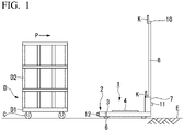
FIG. 1 is a view showing a configuration of a transporter according to a first embodiment. -
FIG. 2 is a perspective view showing the configuration of the transporter according to the first embodiment. -
FIG. 3 is a block diagram showing the configuration of the transporter according to the first embodiment. -
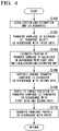
FIG. 4 is a flowchart showing processes carried out by the transporter according to the first embodiment. -
FIG. 5 is a view showing a configuration of a transporter according to a second embodiment. -
FIG. 6 is a block diagram showing the configuration of the transporter according to the second embodiment. -
FIG. 7 is a block diagram showing the configuration of the transporter according to a fifth embodiment. - According to one embodiment, an autonomous mobile robot has a driver, a first detector, a second detector, a localization estimation part, a route-generating part, and a control part. The autonomous mobile robot is autonomously movable. The driver is configured to cause the autonomous mobile robot to move. The first detector is provided at a position higher than a position in height of an object present around the autonomous mobile robot. The first detector is configured to obtain first data by scanning the object at a first region around the autonomous mobile robot. The second detector is configured to obtain second data by scanning the object at a second region around the autonomous mobile robot. The localization estimation part is configured to calculate an estimated position of the autonomous mobile robot in a predetermined region in accordance with the first data. The route-generating part is configured to calculate a position of the object present around the autonomous mobile robot in accordance with the second data. The route-generating part is configured to calculate a route to a target position in accordance with the estimated position and the position of the object. The control part is configured to control the driver in accordance with the route. The control part is configured to cause the autonomous mobile robot to travel to the target position.
- Hereinafter, an autonomous mobile robot, a transporter, an autonomous mobile robot control method, and a transporter control method according to an embodiment will be described with reference to the drawings. In the embodiment, the autonomous mobile robot is applicable to a transporter. In the embodiment, the transporter is configured to transport a transport object. The transporter transfers the transport object in which packages, commercial products, or the like are loaded in a distribution center or a back yard of a shop.
- As shown in
FIGS. 1 and2 , a transporter 1 (referred to as a locomotion robot or an autonomous mobile robot) transports a transport object D. The transport object D is, for example, a roll box pallet. A travel direction P in which the transport object D moves is determined. The transport object D has a lower surface and an upper surface. The transport object D includes, for example, a bottom plate D1 formed in a rectangular plate shape, a plurality of wheels C (leg) provided on the lower surface of the bottom plate D1, and a frame D2 provided on the upper surface of the bottom plate D1. - A transport object (not shown in the drawings) is to be mounted on the upper surface side of the bottom plate D1. The frame D2 is provided so as to surround the transport object on the upper surface side of the bottom plate D1. The frame D2 has four faces. The frame D2 is formed so as to surround a circumference of the transport object, for example, on four surfaces of the transport object above the bottom plate D1. At least one of the four faces of the frame D2 is an openable and closable door. The frame D2 may have a configuration in which one face of the frame D2 is opened without providing a door.
- Four wheels C are disposed at four corners on the lower surface side of the bottom plate D1. The wheels C cause the bottom plate D1 to move with respect to the floor surface E. The wheels C are two pairs of wheels provided on the lower surface side of the bottom plate D1. The two pairs of the wheels are spaced at a predetermined distance in the travel direction P. With the aforementioned configuration, the transport object D travels on the floor surface E when an external force is applied thereto in the travel direction P. The transport object D is transferred to a target position by the
transporter 1. - The
transporter 1 includes, for example, atransfer carriage 2 that transfers the transport object D and a plurality of detectors used for sensing provided at thetransfer carriage 2. The detectors includes afirst detector 10, asecond detector 11, and athird detector 12. Thetransfer carriage 2 includes, for example, aload base 3 having an upper surface. The bottom plate D1 is to be mounted on the upper surface of theload base 3. Theload base 3 has a lower surface. A plurality ofwheels 6 are provided on the lower surface ofload base 3. Thewheels 6 are driven by a driver 14 (refer toFIG. 2 ) as described hereinbelow. As thewheels 6 are driven, theload base 3 can travel on the floor surface E. - The
wheels 6 are driven by a commonly-used two-wheel independent drive system using thedriver 14 described below. As thewheels 6 are driven, thetransporter 1 travels. The direction of movement of thetransporter 1 is controlled by acontrol part 110 as described hereinbelow. Thewheels 6 may be driven by use of a steering wheel or a particular kind of wheel so as to omnidirectionally travel. - The height of the
load base 3 is determined such that theload base 3 can enter into a region between the bottom plate D1 of the transport object D and the floor surface E. A lifter 4 is provided on the upper surface side of theload base 3. The height of the lifter 4 is adjustable. The lifter 4 is controlled by thecontrol part 110 described later. When theload base 3 is inserted between the bottom plate D1 and the floor surface E, the lifter 4 increases the position thereof in height and lifts up the transport object D. Theload base 3 transfers the transport object D in a state in which the transport object D is lifted up by the lifter 4. Theload base 3 may transfer the transport object D while generating a friction between the lower surface side of the bottom plate D1 and an upper surface side of the lifter 4 without lifting up the transport object D. Thetransfer carriage 2 may transfer the transport object D by traction while hooking the transport object D using a pin or the like without providing theload base 3 and the lifter 4. - A
housing 7 is provided at, for example, a front side in the travel direction P on the load base 3 (refer toFIG. 1 ). Acontroller 100 described later is housed in thehousing 7. Thehousing 7 is formed in a rectangular parallelepiped shape. At the front side of theload base 3, thehousing 7 is provided upright from the upper surface side of theload base 3. A rotating light K is provided at an upper surface side of thehousing 7. The rotating light K informs operators around thetransporter 1 that thetransporter 1 is approaching. The rotating light K has a light source, for example, that rotates to cause the operators to visually recognize thetransporter 1, and the rotating light K attracts the attention of the operators to the approachingtransfer carriage 2. - A
support member 8 is provided at an upper surface side of thehousing 7. Thesupport member 8 is formed in a rod shape. Thesupport member 8 is configured to be provided upright. Thesupport member 8 is formed in, for example, a frame shape when viewed from a direction along the travel direction P. Particularly, thesupport member 8 has a configuration in which two rod members are provided upright, and another rod member is further connected to the two rod members so as to intersect therewith. Thesupport member 8 may be formed so as to have a reinforced truss structure that increases bending rigidity in a front-back direction for preventing vibration or may be formed so as to have other structures. - The
first detector 10 and the rotating light K are provided at an upper end of thesupport member 8. Thefirst detector 10 detects an object around thetransporter 1. Thefirst detector 10 is, for example, an LRF (Laser Range Finder). Thefirst detector 10 scans the object with a laser beam, receives reflection light reflected from the object, and measures a distance to the surface of the object in accordance with a phase difference of the reflection light or a differential arrival time. Thefirst detector 10 obtains first data by scanning the object at a first region around thetransfer carriage 2. Thefirst detector 10 scans the object in a predetermined angle range, for example, in a planar direction around thefirst detector 10 and obtains the first data associated with a distance to the surface of the object around thefirst detector 10 at a plurality of points. - The first data is used to generate a localization-and-estimation map of the
transfer carriage 2 as described hereinbelow. In the case in which there is a difference in an ambient environment between a time of generating the localization-and-estimation map and a time of practically carrying out a transfer operation, a degree of accuracy of estimating the localization becomes degraded. In a distribution center, a back yard of a shop, or the like, a human is present around thetransporter 1, other roll box pallets are placed, and the ambient environment of thetransporter 1 varies from hour to hour. Moreover, for example, in a distribution center or a back yard of a shop, commercial products are often on a store shelf or the like near the floor surface, and the number of products temporally varies. - Consequently, depending on the above, a situation of the object to be detected by the LRF may vary temporally. In the distribution center, for example, roll box pallets or operators frequently move, and the object to be detected by the LRF varies. The ambient environment includes an environment inherence object and a surrounding existence object. The environment inherence object means an inherence object, for example, a circumference wall, fixed equipment, a pillar, or the like. It is assumed that the position or the shape of the environment inherence object is not changed when the
transfer carriage 2 is driven. The surrounding existence object is an object other than the environment inherence object of the ambient environment. It is assumed that the position or the shape of the surrounding existence object is changed when thetransfer carriage 2 is driven. The surrounding existence object is, for example, an object present around the transfer carriage 2 (a human, a transport object such as transfer carriage, roll box pallet, or the like). - As compared with the environment inherence object, the surrounding existence object is often located closer to the moving
transfer carriage 2 than the environment inherence object. Furthermore, regarding the ambient environment, the environment inherence object such as the circumference wall, the fixed equipment, the pillar, or the like is not changed. Consequently, thefirst detector 10 is attached to a position in height which is assumed in advance such that the surrounding existence object of the ambient environment such as a transfer object, a movable object, or the like is not present. Particularly, thefirst detector 10 is provided at a position in height of the object (surrounding existence object) present around thetransfer carriage 2. - In an environment in which there are a lot of movable objects or operators are present, it is preferable that the
first detector 10 be attached to a position higher than that of the other transport object (roll box pallet) or the moving obstacle such as a human, which causes the ambient environment to be varied. Thefirst detector 10 is provided at a position, for example, higher than or equal to 1.8 meters, which is a position higher than a body height of a common person. Heights of roll box pallets used in a distribution center or a back yard of a shop are different from each other. Thefirst detector 10 is provided such that the height of thefirst detector 10 is manually adjustable so as to be higher than the position in height of an object, for example, a moving obstacle or the like present around the first detector. Additionally, an adjuster (not shown in the drawings) may be provided at thefirst detector 10. The adjuster can automatically adjust the position of thefirst detector 10 to be higher than the position in height of an object, for example, a moving obstacle or the like present around the first detector. - The
second detector 11 that obtains second data by scanning the object is provided at a second region around thetransfer carriage 2 at the forward side of thehousing 7 in the travel direction P. Thesecond detector 11 is, for example, an LRF. Thesecond detector 11 scans the object with a laser beam, receives reflection light reflected from the object, and measures a distance to the surface of the object in accordance with a phase difference of the reflection light or a differential arrival time. Thesecond detector 11 scans the object in a predetermined angle range, for example, in a planar direction in front of thesecond detector 11 and obtains the second data associated with a distance to the surface of the object in front of thesecond detector 11 at a plurality of points. Thesecond detector 11 detects, for example, a transfer object or a movable object around thesecond detector 11. The movable object means, for example, a shelf that is optionally changeable in position, the other transport object D that is being temporarily halted, a transfer object such as a human, or the like. - The
third detector 12 is provided at the back side of theload base 3 in the travel direction P. Thethird detector 12 obtains third data associated with positions of the wheels 6 (leg) provided at the lower portion of the transport object D. Thethird detector 12 is, for example, an LRF. Thethird detector 12 is attached to a lower position in order to detect thewheels 6. Thethird detector 12 scans thewheels 6 with a laser beam, receives reflection light reflected from thewheels 6, and measures a distance to the surface of thewheel 6 in accordance with a phase difference of the reflection light or a differential arrival time. - The
third detector 12 scans the object in a predetermined angle range, for example, in a planar direction of the laser scanning direction and obtains the third data associated with a distance to the surface of thewheel 6 in front of thethird detector 12 at a plurality of points. As described below, the positions of thewheels 6 supporting the transport object D are obtained in accordance with the third data detected by thethird detector 12, and theload base 3 can be inserted between the pair of thewheels 6 facing each other in the travel direction P. A depth camera capable of obtaining distance information as well as the LRF may be used as thethird detector 12. Thethird detector 12 may be configured of a plurality of infrared distance sensors. - Next, control of the
transporter 1 will be described. - As shown in
FIG. 3 , movement of thetransporter 1 is controlled by thecontroller 100. Thecontroller 100 is housed in, for example, thehousing 7. Thecontroller 100 may be a device that may be configured by a server device and controls thetransfer carriage 2 via a network. Thetransfer carriage 2 includes a power-supply device (not shown in the drawings) as well as the shown configuration. Here, the server device is a device capable of communicating with a plurality oftransfer carriages 2 and is configured to concentratedly control thetransfer carriages 2. For example, the server device includes a communicator configured to communicate with thetransfer carriages 2, a processor such as CPU (Central Processing Unit), a storage, or the like. - The
controller 100 includes, for example, astorage 102, a map-generatingpart 104, alocalization estimation part 106, a route-generatingpart 108, acontrol part 110, and adocking control part 112. Thestorage 102 stores various data. The map-generatingpart 104 generates a map for estimating a position of thetransporter 1. Thelocalization estimation part 106 calculates an estimated position of thetransfer carriage 2 in accordance with the first data obtained by thefirst detector 10 and the map. The route-generatingpart 108 calculates a route to a target position of thetransporter 1 in accordance with the second data obtained by thesecond detector 11 and the estimated position. Thecontrol part 110 controls thedriver 14 in accordance with the third data formed by the route and thethird detector 12 and causes the transfer carriage to travel to the target position. Thedocking control part 112 controls docking with respect to the transport object D. - For example, as a processor such as CPU (Central Processing Unit) executes program (computer program, software) stored in the
storage 102, a part or all of functional parts of the map-generatingpart 104, thelocalization estimation part 106, the route-generatingpart 108, thecontrol part 110, and thedocking control part 112 is operated. Furthermore, a part or all of the functions of the aforementioned constituent parts may be achieved by hardware (circuit part, including circuitry) such as LSI (Large Scale Integration Circuit), ASIC (Application Specific Integrated Circuit), FPGA (Field Programmable Gate Array), GPU (Graphics Processing Unit), or the like, or may be achieved by cooperation of software and hardware. The program may be stored in advance in a storage device such as a HDD (hard disk drive), a flash memory, or the like. The program may be stored in a removable recording medium such as a DVD, a CD-ROM, or the like. By loading the recording medium to a drive device, the program may be installed in the drive device. - A localization-and-estimation map is generated by SLAM in order to estimate the localization of the
transporter 1. In the SLAM, it is assumed that the environment of generating the map is the same as the environment of movement of the locomotion robot. Initially, the localization-and-estimation map is generated by causing thetransporter 1 to travel by a manual operation. When thetransporter 1 travels in a predetermined region such as a business place, that is an object in which thetransporter 1 travels, the first data generated by thefirst detector 10 is stored in thestorage 102. Thestorage 102 is realized by a recording medium, for example, a RAM (Random Access Memory), a ROM (Read Only Memory), a HDD, a flash memory, or the like. - The map-generating
part 104 uses, for example, the first data, calculates a two-dimensional shape associated with the environment inherence object such as the circumference wall, the fixed equipment, or the like, and generates the localization-and-estimation map. The map-generatingpart 104 may generate the localization-and-estimation map in accordance with the first data as well as the localization-and-estimation map in accordance with the second data. The map-generatingpart 104 may separately generate the localization-and-estimation map at the horizontal plane at a measured height of thefirst detector 10 in accordance with construction drawing data. The localization-and-estimation map generated by the map-generatingpart 104 is stored in thestorage 102. - The
localization estimation part 106 calculates two-dimensional distance information associated with the environment inherence object such as the wall around the transporter 1 (the transfer carriage 2), the fixed equipment, or the like in accordance with the first data obtained by thefirst detector 10. Thelocalization estimation part 106 compares the calculated two-dimensional distance information to the localization-and-estimation map and extracts the predetermined region coincident with the two-dimensional distance information from the localization-and-estimation map. - The
localization estimation part 106 calculates a relative angle (posture) and a relative position with respect to a planar direction of thetransporter 1 in the predetermined region extracted in accordance with the extracted predetermined region and the calculated two-dimensional distance information. Thelocalization estimation part 106 calculates an estimated position on the two-dimensional coordinate system of thetransporter 1 in the localization-and-estimation map in accordance with the calculation result. - The route-generating
part 108 calculates the shape of the obstacle present around thetransporter 1 in accordance with the second data obtained by thesecond detector 11. The route-generatingpart 108 compares the two-dimensional distance information associated with the environment inherence object such as the wall around thetransporter 1, the fixed equipment, or the like in the extracted predetermined region and the shape of the object present around thetransporter 1 in accordance with the second data, and extracts the obstacle present around thetransporter 1. The route-generatingpart 108 generates a route from the estimated position of thetransporter 1 to the target position. - At this time, the route-generating
part 108 generates a route that avoids the extracted obstacle. In accordance with the second data, the route-generatingpart 108 updates real-time information associated with the obstacles such as the number, the position, the direction of movement, the speed, the size, or the like at a predetermined timing, and updates route that avoids the obstacle. The predetermined timing is adjusted in accordance with the movement speed of thetransporter 1. The route-generatingpart 108 may not only generate a route that avoids the obstacle in accordance with a moving state of the obstacle but also generate a route that avoids the obstacle by adjusting the speed of thetransfer carriage 2 - The
control part 110 controls thedriver 14 in accordance with the route generated by the route-generatingpart 108 and causes thetransfer carriage 2 to travel along the route. Thedriver 14 independently controls thewheels 6 provided at right and left of thetransfer carriage 2, and controls the speed and the direction of thetransfer carriage 2. Thecontrol part 110 controls thedriver 14 and thereby controls thetransfer carriage 2 so as to be stopped or so as to avoid the obstacle in the case in which the obstacle comes close at a distance to be less than or equal to a previously-set reference. At this time, in the case in which the transport object D being transferred, thecontrol part 110 controls deceleration of thedriver 14 and the direction of the transfer carriage so as to prevent load collapse. - The
control part 110 may cause the rotating light K to change a light emission pattern thereof and to light up in the case in which a human comes close at a distance to be less than or equal to a previously-set reference. As well as the rotating light K, thecontrol part 110 may cause a speaker (not shown in the drawings) to emit sound and thereby notify the human. In the case in which the obstacle is theother transporter 1, thecontrol part 110 may communicate with theother transporter 1 and adjust the relative distance with respect to theother transporter 1. Thecontrol part 110 may communicate with a control apparatus (not shown in the drawings) via a network and adjust the relative position with respect to theother transporter 1. - The
docking control part 112 recognizes arrangement of the wheels C of the transport object D in accordance with the third data obtained by the third detector. Thedocking control part 112 recognizes a space between the wheels C on the lower surface side of the transport object D in accordance with the third data. Thedocking control part 112 recognizes the relative position and the posture of the transport object D. The distance between the pair of the wheels C facing each other in the travel direction P of the transport object D is different from distance between the pair of the wheels C facing each other in the direction orthogonal to the travel direction P. Thedocking control part 112 determines the insertion direction of thetransfer carriage 2 with respect to the transport object D in accordance with the distance between the pair of the wheels C in the recognized travel direction P and the distance between the pair of the wheels C in the direction orthogonal to the travel direction P. Thedocking control part 112 generates a docking route in which thetransfer carriage 2 is inserted between the wheels C in accordance with the third data. - The
control part 110 controls thedriver 14 in accordance with the docking route generated by thedocking control part 112 and causes thetransfer carriage 2 to be disposed at the transport object D. Thecontrol part 110 controls thedriver 14 and causes thetransfer carriage 2 to be inserted into the lower surface side of the transport object D from the back portion thereof. When thetransfer carriage 2 reaches a predetermined position at the lower surface side of the transport object D, thecontrol part 110 causes thedriver 14 to be stopped, controls the lifter 4 so as to lift up the bottom plate D1 of the transport object D, and causes the transport object D to be in a state of being transportable. - Next, a controlling method of the
transporter 1 will be described. -
FIG. 4 shows a flowchart showing processes of a control method of thetransporter 1. First of all, first data and second data are obtained in advance by causing thetransporter 1 to travel by a manual operation in a region of a building or the like in which thetransporter 1 is used. Thelocalization estimation part 106 generates a localization-and-estimation map in accordance with first data (step S100). The first data is obtained by scanning an object at a first region around the transfer carriage at a position higher than the height position of an object present around the transfer carriage transporting a transport object. - The
docking control part 112 recognizes a space between the wheels C of the transport object D in accordance with third data obtained by thethird detector 12. Thecontrol part 110 causes thetransfer carriage 2 to be disposed in the space at the lower side of the transport object D in accordance with the recognized space (step S102). Thelocalization estimation part 106 calculates a shape of a peripheral region in accordance with the first data obtained by thefirst detector 10, compares the calculation result and the localization-and-estimation map, and extracts a predetermined region coincident with the localization-and-estimation map. - The
localization estimation part 106 calculates an estimated position of the transfer carriage in the extracted predetermined region (step S104). The route-generatingpart 108 calculates a shape and a position of the peripheral region in accordance with the second data obtained by scanning the object at a second region around thetransfer carriage 2, and extracts an obstacle around thetransfer carriage 2 in accordance with the calculate shape and the localization-and-estimation map (step S106). The route-generatingpart 108 generates a route to a target position in accordance with the estimated position and generates a route to the target position, which avoids the obstacle in accordance with the first data and the second data (step S108). Thecontrol part 110 controls thedriver 14 in accordance with the route and causes thetransfer carriage 2 to travel to the target position (step S110). In the case in which the other transport object is present, the steps after thestep 102 are repeated. - As described above, according to the
transporter 1, in a distribution center or a back yard of a shop, it is possible to automatically transfer the transport object D such as a roll box pallet or the like, in which, packages, commercial products, or the like are loaded. According to thetransporter 1, since thefirst detector 10 is provided at the position higher than that of the obstacle or the like around the first detector, it is possible to calculate the estimated position of thetransporter 1 without being affected by the obstacle. Since thesecond detector 11 detects the obstacle therearound, thetransporter 1 can travel along the route to the target position while avoiding the obstacle. - Hereinbelow, a second embodiment will be described. In the following description, identical names and identical reference numerals are used for the components which are identical to those of the above-described embodiment, and duplicate description is omitted (the same applies hereinafter).
- As shown in
FIGS. 5 and6 , in a transporter 1A according to the second embodiment, a camera R that captures an image of a circumference of thetransfer carriage 2 at a position at which thefirst detector 10 is provided may be provided. The camera R captures an image of, for example, a wide field of view. The camera R looks down upon the circumference of thetransporter 1 from the position of thefirst detector 10 and captures an image. The camera R may be, for example, a depth camera that calculates a distance to an object. - The
controller 100 may include arecognition part 114 that recognizes the transport object D and an object present around thetransfer carriage 2 in accordance with an image data obtained by the camera R. Therecognition part 114 extracts an obstacle around thetransfer carriage 2 in accordance with the image data. Therecognition part 114 may recognize the transport object D in accordance with the image data. Therecognition part 114 extracts the transport object D in accordance with the image data, and recognizes a distance to the transport object D, a relative posture of the transport object D, and an insertion direction of thetransfer carriage 2. - The
control part 110 controls thedriver 14 based on the recognition result recognized by therecognition part 114, causes thetransfer carriage 2 to travel so as to be inserted into the lower surface side of the transport object D, and causes thetransfer carriage 2 to be disposed at the lower surface side of the transport object D. - The route-generating
part 108 generates a route to a target position, which avoids the obstacle in accordance with the position, the speed, the direction of movement, the size, or the like of the obstacle extracted by therecognition part 114. Thecontrol part 110 causes thetransfer carriage 2 to travel to the target position while avoiding the obstacle in accordance with the generated route. The route-generatingpart 108 may extract the obstacle present in the circumference by use of the image data obtained by the camera R and the second data of thesecond detector 11. As the aforementioned camera R, a plurality of infrared distance sensors that measure a distance may be used. - As described above, according to the transporter 1 A, by use of the camera R, it is possible to easily avoid the obstacle in the circumference. According to the transporter 1A, by use of the camera R, it is possible to dispose the
transfer carriage 2 at the lower surface side of the transport object D. Additionally, when the transport object is unloaded at a transferring place, it is possible to arrange the transport object next to the other transport objects side by side. - In the aforementioned embodiment, an object present around the
transfer carriage 2 is extracted by use of thesecond detector 11 or the camera R. In the third embodiment, the object around thetransfer carriage 2 may be extracted by use of the first data of thefirst detector 10. In the case in which, for example, a three-dimensional LRF that can also carries out scanning in a vertical direction is used as thefirst detector 10, the route-generatingpart 108 may extract an object such as the obstacle or the like around thetransfer carriage 2 in accordance with the first data obtained by thefirst detector 10. - As described above, according to the third embodiment, it is possible to extract the object around the
transfer carriage 2 in accordance with the first data obtained by thefirst detector 10, and it is possible to simplify a device configuration. - The
first detector 10 is attached to a high position via thesupport member 8. Consequently, there is a concern that the value of the first data varies due to an error in position at which thefirst detector 10 is attached or an effect of vibration generated along with movement of thetransfer carriage 2. In the fourth embodiment, thecontroller 100 compares the second data obtained by thesecond detector 11 and the first data obtained by thefirst detector 10, and carries out calibration with respect to an error in position at which the first detector is attached or an error generated due to vibration. - At this time, a measurement object to be measured by the
second detector 11 is selected from the environment inherence objects such as a wall, a pillar, or the like of a building, in which it is assumed that the shape at the detection position of thesecond detector 11 is the substantially same as that of the detection position of thefirst detector 10. Since thesecond detector 11 is provided at thehousing 7 of thetransfer carriage 2, the second data is stabilized more than the first data. For this reason, in thecontroller 100, it is possible to carry out calibration of the first data by carrying out verification by comparing the first data and the second data. The route-generatingpart 108 calculates the shape of the object of the circumference in accordance with the first data. The route-generatingpart 108 calculates the shape of the object of the circumference in accordance with the second data. The route-generatingpart 108 extracts characteristic parts, for example, the wall, the pillar, the corner, or the like of the building in accordance with the first data and the second data. - The route-generating
part 108 compares a second characteristic portion of the building in accordance with the second data and a first characteristic portion of the building in accordance with the first data. The route-generatingpart 108 compares, for example, data associated with a distance, a posture, a shape, or the like of the second characteristic portion and data associated with a distance, a posture, a shape, or the like of the first characteristic portion, and thereby carries out calibration with respect to the error in position at which the first detector is attached or the error generated due to vibration. - According to the fourth embodiment, in the case of measuring the same measurement object by the
second detector 11 and thefirst detector 10, the first data is compared to the second data stabilized more than the first data. As a result, it is possible to carry out the calibration with respect to the error in position at which thefirst detector 10 is attached or the error generated due to vibration which is included in the first data. - In the fourth embodiment, the calibration with respect to the error in position at which the
first detector 10 is attached or the error generated due to vibration which is included in the first data is carried out by comparing the first data of thefirst detector 10 and the second data of thesecond detector 11. In the fifth embodiment, the first data is corrected by detecting swing of thefirst detector 10. - As shown in
FIG. 7 , atransporter 1B includes a fourth detector V that obtains fourth data representing swing of thefirst detector 10 of thetransfer carriage 2. The fourth detector V is, for example, a six-axis acceleration sensor (inertial sensor). The fourth detector V is attached to a position near, for example, thefirst detector 10. Thelocalization estimation part 106 calculates the posture of thefirst detector 10 in accordance with the fourth data obtained by the fourth detector V. In accordance with the calculated posture, thelocalization estimation part 106 corrects the first data obtained by thefirst detector 10 to be data associated with a state in which swing is not generated. - In each of the aforementioned embodiments, although the map-generating
part 104, thelocalization estimation part 106, the route-generatingpart 108, thedocking control part 112, and therecognition part 114 are each software functional part, each of them may be a hardware functional part such as LSI or the like. - According to at least one embodiment described above, the autonomous mobile robot is autonomously movable, a
driver 14 configured to cause the autonomous mobile robot to move; afirst detector 10 provided at a position higher than a position in height of an object present around the autonomous mobile robot, the first detector being configured to obtain first data by scanning the object at a first region around the autonomous mobile robot; asecond detector 11 configured to obtain second data by scanning the object at a second region around the autonomous mobile robot; alocalization estimation part 106 configured to calculate an estimated position of the autonomous mobile robot in a predetermined region in accordance with the first data; a route-generatingpart 108 configured to calculate a position of the object present around the autonomous mobile robot in accordance with the second data, the route-generating part being configured to calculate a route to a target position in accordance with the estimated position and the position of the object; and acontrol part 110 configured to control the driver in accordance with the route, the control part being configured to cause the autonomous mobile robot to travel to the target position. Accordingly, the autonomous mobile robot can automatically travel in the environment in which a movable object is present around the autonomous mobile robot. - While certain embodiments have been described, these embodiments have been presented by way of example only, and are not intended to limit the scope of the inventions. Indeed, the novel embodiments described herein may be embodied in a variety of other forms; furthermore, various omissions, substitutions and changes in the form of the embodiments described herein may be made without departing from the inventions. The accompanying claims and their equivalents are intended to cover such forms or modifications as would fall within the scope of the inventions.
- 1...transporter, 1A...transporter, 1B...transporter, 2...transfer carriage, 3...load base, 4...lifter, 6...wheel, 7...housing, 8...support member, 10...first detector, 11...second detector, 12...third detector, 14...driver, 100...controller, 102...storage, 104...map-generating part, 106...localization estimation part, 108...route-generating part, 110...control part, 112...docking control part, 114...recognition part, C...wheel, D...transport object, D1...bottom plate, D2...frame, E...floor surface, K...rotating light, R...camera, V...fourth detector
Claims (16)
- An autonomous mobile robot, comprising:a driver configured to cause the autonomous mobile robot to move;a first detector provided at a position higher than a position in height of an object present around the autonomous mobile robot, the first detector being configured to obtain first data by scanning the object at a first region around the autonomous mobile robot;a second detector configured to obtain second data by scanning the object at a second region around the autonomous mobile robot;a localization estimation part configured to calculate an estimated position of the autonomous mobile robot in a predetermined region in accordance with the first data;a route-generating part configured to calculate a position of the object present around the autonomous mobile robot in accordance with the second data, the route-generating part being configured to calculate a route to a target position in accordance with the estimated position and the position of the object; anda control part configured to control the driver in accordance with the route, the control part being configured to cause the autonomous mobile robot to travel to the target position.
- The autonomous mobile robot according to claim 1, wherein
the object present around the autonomous mobile robot is movable. - The autonomous mobile robot according to claim 1, wherein
the object present around the autonomous mobile robot is changeable in shape. - A transporter comprising an autonomous mobile robot configured to transport a transport object,
the autonomous mobile robot comprising:a driver configured to cause the autonomous mobile robot to move;a first detector provided at a position higher than a position in height of an object present around the autonomous mobile robot, the first detector being configured to obtain first data by scanning the object at a first region around the autonomous mobile robot;a second detector configured to obtain second data by scanning the object at a second region around the autonomous mobile robot;a localization estimation part configured to calculate an estimated position of the autonomous mobile robot in a predetermined region in accordance with the first data;a route-generating part configured to calculate a position of an object present around the autonomous mobile robot in accordance with the second data, the route-generating part being configured to calculate a route to a target position in accordance with the estimated position and the position of the object; anda control part configured to control the driver in accordance with the route, the control part being configured to cause the autonomous mobile robot to travel to the target position. - The transporter according to claim 4, wherein
the autonomous mobile robot is a transfer carriage configured to transport the transport object. - The transporter according to claim 4, wherein
the first detector is adjustable in height to be higher than the position in height of the object. - The transporter according to any one of claims 4 to 6, wherein
the first detector is provided at a position in height higher than 1.8 m. - The transporter according to any one of claims 4 to 7, further comprising:a third detector configured to obtain third data associated with a position of a leg provided under the transport object, whereinthe control part controls the driver in accordance with the third data to cause the autonomous mobile robot to be disposed at the transport object.
- The transporter according to any one of claims 4 to 8, further comprising:a camera configured to capture an image of a region around the autonomous mobile robot at a position at which the first detector is provided; anda recognition part configured to recognize the transport object and the object in accordance with image data obtained by the camera, whereinthe control part controls the driver in accordance with a recognition result recognized by the recognition part to cause the autonomous mobile robot to travel.
- The transporter according to any one of claims 4 to 9, wherein
the route-generating part calculates a position of the object in accordance with the first data. - The transporter according to any one of claims 4 to 10, wherein
the route-generating part compares the second data to the first data and calibrates an error in position at which the first detector is provided. - The transporter according to any one of claims 4 to 11, further comprising:a fourth detector configured to obtain fourth data representing swing of the first detector, whereinthe localization estimation part corrects the first data in accordance with the fourth data.
- An autonomous mobile robot control method, comprising:obtaining first data by scanning an object at a position higher than a position in height of the object present around an autonomous mobile robot at a first region around the autonomous mobile robot;obtaining second data by scanning the object at a second region around the autonomous mobile robot;calculating an estimated position of the autonomous mobile robot in a predetermined region in accordance with the first data;calculating a position of the object in accordance with the second data;calculating a route to a target position in accordance with the estimated position and the position of the object; andcontrolling a driver in accordance with the route, the driver being configured to cause the autonomous mobile robot to transfer, causing the autonomous mobile robot to travel to the target position.
- The autonomous mobile robot control method according to claim 13, wherein the object present around the autonomous mobile robot is movable.
- The autonomous mobile robot control method according to claim 13 or claim 14, wherein
the object present around the autonomous mobile robot is changeable in shape. - A transporter control method, comprising:obtaining first data by scanning an object at a position higher than a position in height of the object present around an autonomous mobile robot at a first region around the autonomous mobile robot, the autonomous mobile robot being configured to transport a transport object;obtaining second data by scanning the object at a second region around the autonomous mobile robot;calculating an estimated position of the autonomous mobile robot in a predetermined region in accordance with the first data;calculating a position of the object in accordance with the second data;calculating a route to a target position in accordance with the estimated position and the position of the object; andcontrolling a driver in accordance with the route, the driver being configured to cause the autonomous mobile robot to transfer, causing the autonomous mobile robot to travel to the target position.
Applications Claiming Priority (1)
| Application Number | Priority Date | Filing Date | Title |
|---|---|---|---|
| JP2020186088 | 2020-11-06 |
Publications (2)
| Publication Number | Publication Date |
|---|---|
| EP3995925A1 true EP3995925A1 (en) | 2022-05-11 |
| EP3995925B1 EP3995925B1 (en) | 2023-08-30 |
Family
ID=78528829
Family Applications (1)
| Application Number | Title | Priority Date | Filing Date |
|---|---|---|---|
| EP21206670.8A Active EP3995925B1 (en) | 2020-11-06 | 2021-11-05 | Autonomous mobile robot, transporter, autonomous mobile robot control method, and transporter control method |
Country Status (4)
| Country | Link |
|---|---|
| US (1) | US20220144609A1 (en) |
| EP (1) | EP3995925B1 (en) |
| JP (1) | JP2022075659A (en) |
| CN (1) | CN114527742B (en) |
Cited By (1)
| Publication number | Priority date | Publication date | Assignee | Title |
|---|---|---|---|---|
| EP4276564A1 (en) * | 2022-12-23 | 2023-11-15 | Hiab AB | Image and range sensor-based position controller and associated method |
Families Citing this family (10)
| Publication number | Priority date | Publication date | Assignee | Title |
|---|---|---|---|---|
| JP7159083B2 (en) * | 2019-03-06 | 2022-10-24 | 株式会社クボタ | work vehicle |
| JP7524882B2 (en) * | 2021-11-15 | 2024-07-30 | トヨタ自動車株式会社 | CONTROL SYSTEM, CONTROL METHOD, AND PROGRAM |
| US12227218B1 (en) * | 2022-03-28 | 2025-02-18 | Amazon Technologies, Inc. | Cart lift robotic transport |
| CA3246785A1 (en) * | 2022-03-28 | 2023-10-05 | Seegrid Corporation | A system for amrs that leverages priors when localizing and manipulating industrial infrastructure |
| JP7537468B2 (en) * | 2022-04-28 | 2024-08-21 | トヨタ自動車株式会社 | Notification system, vehicle transport system, computer program, and notification method |
| KR102814901B1 (en) * | 2022-12-12 | 2025-06-02 | 현대모비스 주식회사 | Lighting device and method for vehicle |
| JP2024154469A (en) * | 2023-04-19 | 2024-10-31 | トヨタ自動車株式会社 | CONTROL SYSTEM, CONTROL METHOD, AND PROGRAM |
| CN116605124B (en) * | 2023-06-16 | 2026-03-06 | 鞍钢集团工程技术有限公司 | A non-tractor-driven metallurgical vehicle |
| WO2025197012A1 (en) | 2024-03-21 | 2025-09-25 | 株式会社LexxPluss | Route generation system for mobile body, route generation method, and program |
| US20260048970A1 (en) * | 2024-08-19 | 2026-02-19 | Fox Robotics, Inc. | Systems and methods for load height and overhead clearance estimation for the autonomous loading and unloading of pallets |
Citations (4)
| Publication number | Priority date | Publication date | Assignee | Title |
|---|---|---|---|---|
| US20150362921A1 (en) * | 2013-02-27 | 2015-12-17 | Sharp Kabushiki Kaisha | Surrounding environment recognition device, autonomous mobile system using same, and surrounding environment recognition method |
| US20170153641A1 (en) * | 2015-12-01 | 2017-06-01 | Keiichi Serizawa | Autonomous traveling device |
| US20180180421A1 (en) * | 2016-12-23 | 2018-06-28 | X Development Llc | Localization of Robotic Vehicles |
| WO2021170852A1 (en) * | 2020-02-28 | 2021-09-02 | Tretyakov Slava | Method for controlling an automatic guided vehicle and control system adapted to execute the method |
Family Cites Families (41)
| Publication number | Priority date | Publication date | Assignee | Title |
|---|---|---|---|---|
| JP2849127B2 (en) * | 1989-09-29 | 1999-01-20 | マツダ株式会社 | Mobile vehicle environment recognition device |
| JP3252618B2 (en) * | 1994-10-13 | 2002-02-04 | 村田機械株式会社 | Automatic guided vehicle |
| SE0004465D0 (en) * | 2000-12-04 | 2000-12-04 | Abb Ab | Robot system |
| JP3995412B2 (en) * | 2000-12-25 | 2007-10-24 | Tcm株式会社 | Work vehicle with traversing system |
| JP3510853B2 (en) * | 2000-12-27 | 2004-03-29 | 川崎重工業株式会社 | Transfer device with robot |
| JP3565178B2 (en) * | 2001-03-23 | 2004-09-15 | オムロン株式会社 | Displacement sensor |
| US20110301757A1 (en) * | 2008-02-21 | 2011-12-08 | Harvest Automation, Inc. | Adaptable container handling robot with boundary sensing subsystem |
| JP5255366B2 (en) * | 2008-08-11 | 2013-08-07 | 株式会社日立産機システム | Transfer robot system |
| JP5699471B2 (en) * | 2010-07-22 | 2015-04-08 | 村田機械株式会社 | Transfer device and fork attachment |
| JP5776332B2 (en) * | 2011-05-27 | 2015-09-09 | 富士通株式会社 | Map processing method and program, and robot system |
| DE102011089858A1 (en) * | 2011-12-23 | 2013-06-27 | Krones Ag | System for transporting goods arranged on auxiliary means |
| EP3000771B1 (en) * | 2014-09-25 | 2017-11-22 | Toyota Material Handling Manufacturing Sweden AB | Fork-lift truck |
| GB2531776B (en) * | 2014-10-30 | 2017-12-20 | Jaguar Land Rover Ltd | Controlling the operation of a vehicle brake system |
| JP6559413B2 (en) * | 2014-11-13 | 2019-08-14 | 株式会社東芝 | Transfer device and baggage removal method |
| US20160260142A1 (en) * | 2015-03-06 | 2016-09-08 | Wal-Mart Stores, Inc. | Shopping facility assistance systems, devices and methods to support requesting in-person assistance |
| US9561941B1 (en) * | 2015-03-30 | 2017-02-07 | X Development Llc | Autonomous approach and object pickup |
| DE102015004330A1 (en) * | 2015-04-09 | 2016-10-13 | Eisenmann Se | Position and position recognition for a conveyor |
| CN105004620B (en) * | 2015-07-16 | 2017-09-26 | 浙江工业大学 | A kind of dynamic load error compensating method of HF fatigue testing machine |
| JP2017033450A (en) * | 2015-08-05 | 2017-02-09 | 日本精工株式会社 | Moving robot |
| JP2017178567A (en) * | 2016-03-30 | 2017-10-05 | 株式会社豊田中央研究所 | forklift |
| JP6698479B2 (en) * | 2016-09-06 | 2020-05-27 | シャープ株式会社 | Autonomous traveling device |
| KR102326077B1 (en) * | 2017-06-15 | 2021-11-12 | 엘지전자 주식회사 | Method of identifying movable obstacle in 3-dimensional space and robot implementing thereof |
| JP2019059460A (en) * | 2017-09-22 | 2019-04-18 | トピー工業株式会社 | Robot for load-carrying platform conveyance |
| WO2019063816A1 (en) * | 2017-09-29 | 2019-04-04 | Roeq Aps | System for connecting an autonomous mobile robot |
| US11014238B2 (en) * | 2017-11-27 | 2021-05-25 | Amazon Technologies, Inc. | Dynamic navigation of autonomous vehicle with safety infrastructure |
| JP6797848B2 (en) * | 2018-01-04 | 2020-12-09 | 株式会社東芝 | Automated guided vehicle |
| CN208684316U (en) * | 2018-05-02 | 2019-04-02 | 汇专科技集团股份有限公司 | A kind of AGV laser fork truck gantry upper frame structure |
| CN113163918B (en) * | 2018-08-28 | 2023-03-28 | 灵动科技(北京)有限公司 | Autopilot system with inventory carrying trolley |
| US20200130510A1 (en) * | 2018-10-30 | 2020-04-30 | Brandon Eck | System and method for autonomous shipping |
| US11215990B2 (en) * | 2018-11-02 | 2022-01-04 | Lingdong Technology (Beijing) Co. Ltd | Manual direction control component for self-driving vehicle |
| CN110770600B (en) * | 2018-11-29 | 2023-04-14 | 深圳市大疆创新科技有限公司 | Distributed Light Detection and Ranging (LIDAR) Management System |
| JP7208783B2 (en) * | 2018-12-20 | 2023-01-19 | 前田建設工業株式会社 | automatic chair placement system |
| JP7163782B2 (en) * | 2019-01-15 | 2022-11-01 | 株式会社豊田自動織機 | Autonomous cart |
| DE102019201595A1 (en) * | 2019-02-07 | 2020-08-13 | Bhs Intralogistics Gmbh | Transfer system |
| KR20210132674A (en) * | 2019-02-19 | 2021-11-04 | 크라운 이큅먼트 코포레이션 | Systems and methods for calibration of the pose of a sensor relative to a material handling vehicle |
| CN114341450B (en) * | 2019-08-12 | 2024-05-31 | N.M.B.医疗应用有限公司 | Autonomous system for diverting vehicles |
| US11649147B2 (en) * | 2019-09-20 | 2023-05-16 | Clearpath Robotics Inc. | Autonomous material transport vehicles, and systems and methods of operating thereof |
| DE102019215176A1 (en) * | 2019-10-02 | 2021-04-08 | Robert Bosch Gmbh | Industrial truck, set up for driverless, autonomous operation for a load to be transported |
| DE102020006337A1 (en) * | 2019-10-09 | 2021-04-15 | Metralabs Gmbh Neue Technologien Und Systeme | Autonomous industrial truck |
| US11459221B2 (en) * | 2020-04-24 | 2022-10-04 | Autoguide, LLC | Robot for stacking elements |
| CN112859832A (en) * | 2020-07-06 | 2021-05-28 | 丰疆智能(深圳)有限公司 | Mobile robot with height-adjustable sensor and method for adjusting height of sensor |
-
2021
- 2021-11-05 US US17/520,269 patent/US20220144609A1/en active Pending
- 2021-11-05 EP EP21206670.8A patent/EP3995925B1/en active Active
- 2021-11-05 CN CN202111304127.9A patent/CN114527742B/en active Active
- 2021-11-08 JP JP2021182160A patent/JP2022075659A/en active Pending
Patent Citations (4)
| Publication number | Priority date | Publication date | Assignee | Title |
|---|---|---|---|---|
| US20150362921A1 (en) * | 2013-02-27 | 2015-12-17 | Sharp Kabushiki Kaisha | Surrounding environment recognition device, autonomous mobile system using same, and surrounding environment recognition method |
| US20170153641A1 (en) * | 2015-12-01 | 2017-06-01 | Keiichi Serizawa | Autonomous traveling device |
| US20180180421A1 (en) * | 2016-12-23 | 2018-06-28 | X Development Llc | Localization of Robotic Vehicles |
| WO2021170852A1 (en) * | 2020-02-28 | 2021-09-02 | Tretyakov Slava | Method for controlling an automatic guided vehicle and control system adapted to execute the method |
Cited By (3)
| Publication number | Priority date | Publication date | Assignee | Title |
|---|---|---|---|---|
| EP4276564A1 (en) * | 2022-12-23 | 2023-11-15 | Hiab AB | Image and range sensor-based position controller and associated method |
| EP4468105A2 (en) | 2022-12-23 | 2024-11-27 | Hiab AB | Image and range sensor-based position controller and associated method |
| EP4671900A1 (en) | 2022-12-23 | 2025-12-31 | Hiab AB | Image and distance sensor-based position control and associated method |
Also Published As
| Publication number | Publication date |
|---|---|
| JP2022075659A (en) | 2022-05-18 |
| CN114527742A (en) | 2022-05-24 |
| CN114527742B (en) | 2025-12-23 |
| EP3995925B1 (en) | 2023-08-30 |
| US20220144609A1 (en) | 2022-05-12 |
Similar Documents
| Publication | Publication Date | Title |
|---|---|---|
| EP3995925B1 (en) | Autonomous mobile robot, transporter, autonomous mobile robot control method, and transporter control method | |
| JP7469494B2 (en) | Method for controlling an automated guided vehicle and a control system configured to carry out said method - Patents.com | |
| JP5255366B2 (en) | Transfer robot system | |
| JP7500484B2 (en) | Automated guided vehicles, automated guided vehicles systems and transport programs | |
| CN113387302B (en) | Mobile control system, mobile body, control method and storage medium | |
| JP7003097B2 (en) | Automated guided vehicle | |
| US20230348248A1 (en) | Transfer system, control device, mobile body, method for controlling mobile body, and storage medium | |
| JP2017534836A (en) | Combination of stereo processing and structured light processing | |
| JP7646473B2 (en) | DETECTION SYSTEM, PROCESSING DEVICE, MOBILE BODY, DETECTION METHOD, AND PROGRAM | |
| JP2021037776A (en) | Automated guided vehicle | |
| JP7511504B2 (en) | MOBILE BODY, MOBILE CONTROL SYSTEM, AND METHOD AND PROGRAM FOR CONTROLLING MOBILE BODY | |
| JP2019053391A (en) | Moving body | |
| CN114555511B (en) | Spreader position control | |
| JP2022028342A (en) | Unmanned conveyance vehicle system | |
| CN111971633A (en) | Position estimation system, mobile object having the same, and computer program | |
| US12209004B2 (en) | Initial setting method of unmanned forklift, palette for adjustment, and adjustment system of unmanned forklift | |
| JP6937416B2 (en) | Transport equipment and programs | |
| US20250340416A1 (en) | Path specification system, path specification apparatus, and path specification method | |
| JP7775779B2 (en) | Cargo Handling System | |
| US12540064B2 (en) | Systems and methods for generating coverage fields for obstacle detection | |
| JP6687313B1 (en) | Transport system | |
| US20240308827A1 (en) | Load Handling Sensors for a Material Handling Vehicle | |
| JP2025134301A (en) | Position and Orientation Detection System | |
| HK40114557A (en) | Load handling sensors for a material handling vehicle | |
| HK40110298A (en) | Systems and methods for generating coverage fields for obstacle detection |
Legal Events
| Date | Code | Title | Description |
|---|---|---|---|
| PUAI | Public reference made under article 153(3) epc to a published international application that has entered the european phase |
Free format text: ORIGINAL CODE: 0009012 |
|
| STAA | Information on the status of an ep patent application or granted ep patent |
Free format text: STATUS: REQUEST FOR EXAMINATION WAS MADE |
|
| 17P | Request for examination filed |
Effective date: 20211105 |
|
| AK | Designated contracting states |
Kind code of ref document: A1 Designated state(s): AL AT BE BG CH CY CZ DE DK EE ES FI FR GB GR HR HU IE IS IT LI LT LU LV MC MK MT NL NO PL PT RO RS SE SI SK SM TR |
|
| GRAP | Despatch of communication of intention to grant a patent |
Free format text: ORIGINAL CODE: EPIDOSNIGR1 |
|
| STAA | Information on the status of an ep patent application or granted ep patent |
Free format text: STATUS: GRANT OF PATENT IS INTENDED |
|
| INTG | Intention to grant announced |
Effective date: 20230310 |
|
| GRAS | Grant fee paid |
Free format text: ORIGINAL CODE: EPIDOSNIGR3 |
|
| GRAA | (expected) grant |
Free format text: ORIGINAL CODE: 0009210 |
|
| STAA | Information on the status of an ep patent application or granted ep patent |
Free format text: STATUS: THE PATENT HAS BEEN GRANTED |
|
| AK | Designated contracting states |
Kind code of ref document: B1 Designated state(s): AL AT BE BG CH CY CZ DE DK EE ES FI FR GB GR HR HU IE IS IT LI LT LU LV MC MK MT NL NO PL PT RO RS SE SI SK SM TR |
|
| REG | Reference to a national code |
Ref country code: GB Ref legal event code: FG4D |
|
| REG | Reference to a national code |
Ref country code: CH Ref legal event code: EP |
|
| REG | Reference to a national code |
Ref country code: DE Ref legal event code: R096 Ref document number: 602021004703 Country of ref document: DE |
|
| REG | Reference to a national code |
Ref country code: IE Ref legal event code: FG4D |
|
| REG | Reference to a national code |
Ref country code: DE Ref legal event code: R079 Ref document number: 602021004703 Country of ref document: DE Free format text: PREVIOUS MAIN CLASS: G05D0001020000 Ipc: G05D0001430000 |
|
| REG | Reference to a national code |
Ref country code: LT Ref legal event code: MG9D |
|
| REG | Reference to a national code |
Ref country code: NL Ref legal event code: MP Effective date: 20230830 |
|
| REG | Reference to a national code |
Ref country code: AT Ref legal event code: MK05 Ref document number: 1606244 Country of ref document: AT Kind code of ref document: T Effective date: 20230830 |
|
| PG25 | Lapsed in a contracting state [announced via postgrant information from national office to epo] |
Ref country code: GR Free format text: LAPSE BECAUSE OF FAILURE TO SUBMIT A TRANSLATION OF THE DESCRIPTION OR TO PAY THE FEE WITHIN THE PRESCRIBED TIME-LIMIT Effective date: 20231201 |
|
| PG25 | Lapsed in a contracting state [announced via postgrant information from national office to epo] |
Ref country code: IS Free format text: LAPSE BECAUSE OF FAILURE TO SUBMIT A TRANSLATION OF THE DESCRIPTION OR TO PAY THE FEE WITHIN THE PRESCRIBED TIME-LIMIT Effective date: 20231230 |
|
| PG25 | Lapsed in a contracting state [announced via postgrant information from national office to epo] |
Ref country code: SE Free format text: LAPSE BECAUSE OF FAILURE TO SUBMIT A TRANSLATION OF THE DESCRIPTION OR TO PAY THE FEE WITHIN THE PRESCRIBED TIME-LIMIT Effective date: 20230830 Ref country code: RS Free format text: LAPSE BECAUSE OF FAILURE TO SUBMIT A TRANSLATION OF THE DESCRIPTION OR TO PAY THE FEE WITHIN THE PRESCRIBED TIME-LIMIT Effective date: 20230830 Ref country code: NO Free format text: LAPSE BECAUSE OF FAILURE TO SUBMIT A TRANSLATION OF THE DESCRIPTION OR TO PAY THE FEE WITHIN THE PRESCRIBED TIME-LIMIT Effective date: 20231130 Ref country code: LV Free format text: LAPSE BECAUSE OF FAILURE TO SUBMIT A TRANSLATION OF THE DESCRIPTION OR TO PAY THE FEE WITHIN THE PRESCRIBED TIME-LIMIT Effective date: 20230830 Ref country code: LT Free format text: LAPSE BECAUSE OF FAILURE TO SUBMIT A TRANSLATION OF THE DESCRIPTION OR TO PAY THE FEE WITHIN THE PRESCRIBED TIME-LIMIT Effective date: 20230830 Ref country code: IS Free format text: LAPSE BECAUSE OF FAILURE TO SUBMIT A TRANSLATION OF THE DESCRIPTION OR TO PAY THE FEE WITHIN THE PRESCRIBED TIME-LIMIT Effective date: 20231230 Ref country code: HR Free format text: LAPSE BECAUSE OF FAILURE TO SUBMIT A TRANSLATION OF THE DESCRIPTION OR TO PAY THE FEE WITHIN THE PRESCRIBED TIME-LIMIT Effective date: 20230830 Ref country code: GR Free format text: LAPSE BECAUSE OF FAILURE TO SUBMIT A TRANSLATION OF THE DESCRIPTION OR TO PAY THE FEE WITHIN THE PRESCRIBED TIME-LIMIT Effective date: 20231201 Ref country code: FI Free format text: LAPSE BECAUSE OF FAILURE TO SUBMIT A TRANSLATION OF THE DESCRIPTION OR TO PAY THE FEE WITHIN THE PRESCRIBED TIME-LIMIT Effective date: 20230830 Ref country code: AT Free format text: LAPSE BECAUSE OF FAILURE TO SUBMIT A TRANSLATION OF THE DESCRIPTION OR TO PAY THE FEE WITHIN THE PRESCRIBED TIME-LIMIT Effective date: 20230830 |
|
| PG25 | Lapsed in a contracting state [announced via postgrant information from national office to epo] |
Ref country code: PL Free format text: LAPSE BECAUSE OF FAILURE TO SUBMIT A TRANSLATION OF THE DESCRIPTION OR TO PAY THE FEE WITHIN THE PRESCRIBED TIME-LIMIT Effective date: 20230830 Ref country code: NL Free format text: LAPSE BECAUSE OF FAILURE TO SUBMIT A TRANSLATION OF THE DESCRIPTION OR TO PAY THE FEE WITHIN THE PRESCRIBED TIME-LIMIT Effective date: 20230830 |
|
| PG25 | Lapsed in a contracting state [announced via postgrant information from national office to epo] |
Ref country code: ES Free format text: LAPSE BECAUSE OF FAILURE TO SUBMIT A TRANSLATION OF THE DESCRIPTION OR TO PAY THE FEE WITHIN THE PRESCRIBED TIME-LIMIT Effective date: 20230830 |
|
| PG25 | Lapsed in a contracting state [announced via postgrant information from national office to epo] |
Ref country code: SM Free format text: LAPSE BECAUSE OF FAILURE TO SUBMIT A TRANSLATION OF THE DESCRIPTION OR TO PAY THE FEE WITHIN THE PRESCRIBED TIME-LIMIT Effective date: 20230830 Ref country code: RO Free format text: LAPSE BECAUSE OF FAILURE TO SUBMIT A TRANSLATION OF THE DESCRIPTION OR TO PAY THE FEE WITHIN THE PRESCRIBED TIME-LIMIT Effective date: 20230830 Ref country code: ES Free format text: LAPSE BECAUSE OF FAILURE TO SUBMIT A TRANSLATION OF THE DESCRIPTION OR TO PAY THE FEE WITHIN THE PRESCRIBED TIME-LIMIT Effective date: 20230830 Ref country code: EE Free format text: LAPSE BECAUSE OF FAILURE TO SUBMIT A TRANSLATION OF THE DESCRIPTION OR TO PAY THE FEE WITHIN THE PRESCRIBED TIME-LIMIT Effective date: 20230830 Ref country code: DK Free format text: LAPSE BECAUSE OF FAILURE TO SUBMIT A TRANSLATION OF THE DESCRIPTION OR TO PAY THE FEE WITHIN THE PRESCRIBED TIME-LIMIT Effective date: 20230830 Ref country code: CZ Free format text: LAPSE BECAUSE OF FAILURE TO SUBMIT A TRANSLATION OF THE DESCRIPTION OR TO PAY THE FEE WITHIN THE PRESCRIBED TIME-LIMIT Effective date: 20230830 Ref country code: SK Free format text: LAPSE BECAUSE OF FAILURE TO SUBMIT A TRANSLATION OF THE DESCRIPTION OR TO PAY THE FEE WITHIN THE PRESCRIBED TIME-LIMIT Effective date: 20230830 Ref country code: PT Free format text: LAPSE BECAUSE OF FAILURE TO SUBMIT A TRANSLATION OF THE DESCRIPTION OR TO PAY THE FEE WITHIN THE PRESCRIBED TIME-LIMIT Effective date: 20240102 |
|
| PG25 | Lapsed in a contracting state [announced via postgrant information from national office to epo] |
Ref country code: IT Free format text: LAPSE BECAUSE OF FAILURE TO SUBMIT A TRANSLATION OF THE DESCRIPTION OR TO PAY THE FEE WITHIN THE PRESCRIBED TIME-LIMIT Effective date: 20230830 |
|
| REG | Reference to a national code |
Ref country code: DE Ref legal event code: R097 Ref document number: 602021004703 Country of ref document: DE |
|
| PG25 | Lapsed in a contracting state [announced via postgrant information from national office to epo] |
Ref country code: MC Free format text: LAPSE BECAUSE OF FAILURE TO SUBMIT A TRANSLATION OF THE DESCRIPTION OR TO PAY THE FEE WITHIN THE PRESCRIBED TIME-LIMIT Effective date: 20230830 |
|
| PLBE | No opposition filed within time limit |
Free format text: ORIGINAL CODE: 0009261 |
|
| STAA | Information on the status of an ep patent application or granted ep patent |
Free format text: STATUS: NO OPPOSITION FILED WITHIN TIME LIMIT |
|
| PG25 | Lapsed in a contracting state [announced via postgrant information from national office to epo] |
Ref country code: LU Free format text: LAPSE BECAUSE OF NON-PAYMENT OF DUE FEES Effective date: 20231105 |
|
| PG25 | Lapsed in a contracting state [announced via postgrant information from national office to epo] |
Ref country code: MC Free format text: LAPSE BECAUSE OF FAILURE TO SUBMIT A TRANSLATION OF THE DESCRIPTION OR TO PAY THE FEE WITHIN THE PRESCRIBED TIME-LIMIT Effective date: 20230830 Ref country code: LU Free format text: LAPSE BECAUSE OF NON-PAYMENT OF DUE FEES Effective date: 20231105 Ref country code: SI Free format text: LAPSE BECAUSE OF FAILURE TO SUBMIT A TRANSLATION OF THE DESCRIPTION OR TO PAY THE FEE WITHIN THE PRESCRIBED TIME-LIMIT Effective date: 20230830 |
|
| REG | Reference to a national code |
Ref country code: BE Ref legal event code: MM Effective date: 20231130 |
|
| 26N | No opposition filed |
Effective date: 20240603 |
|
| REG | Reference to a national code |
Ref country code: IE Ref legal event code: MM4A |
|
| PG25 | Lapsed in a contracting state [announced via postgrant information from national office to epo] |
Ref country code: IE Free format text: LAPSE BECAUSE OF NON-PAYMENT OF DUE FEES Effective date: 20231105 |
|
| PG25 | Lapsed in a contracting state [announced via postgrant information from national office to epo] |
Ref country code: BE Free format text: LAPSE BECAUSE OF NON-PAYMENT OF DUE FEES Effective date: 20231130 |
|
| PG25 | Lapsed in a contracting state [announced via postgrant information from national office to epo] |
Ref country code: FR Free format text: LAPSE BECAUSE OF NON-PAYMENT OF DUE FEES Effective date: 20231130 |
|
| PG25 | Lapsed in a contracting state [announced via postgrant information from national office to epo] |
Ref country code: IE Free format text: LAPSE BECAUSE OF NON-PAYMENT OF DUE FEES Effective date: 20231105 Ref country code: FR Free format text: LAPSE BECAUSE OF NON-PAYMENT OF DUE FEES Effective date: 20231130 Ref country code: BE Free format text: LAPSE BECAUSE OF NON-PAYMENT OF DUE FEES Effective date: 20231130 |
|
| PG25 | Lapsed in a contracting state [announced via postgrant information from national office to epo] |
Ref country code: BG Free format text: LAPSE BECAUSE OF FAILURE TO SUBMIT A TRANSLATION OF THE DESCRIPTION OR TO PAY THE FEE WITHIN THE PRESCRIBED TIME-LIMIT Effective date: 20230830 |
|
| PG25 | Lapsed in a contracting state [announced via postgrant information from national office to epo] |
Ref country code: BG Free format text: LAPSE BECAUSE OF FAILURE TO SUBMIT A TRANSLATION OF THE DESCRIPTION OR TO PAY THE FEE WITHIN THE PRESCRIBED TIME-LIMIT Effective date: 20230830 |
|
| REG | Reference to a national code |
Ref country code: CH Ref legal event code: PL |
|
| REG | Reference to a national code |
Ref country code: CH Ref legal event code: PL |
|
| PG25 | Lapsed in a contracting state [announced via postgrant information from national office to epo] |
Ref country code: CH Free format text: LAPSE BECAUSE OF NON-PAYMENT OF DUE FEES Effective date: 20241130 |
|
| PG25 | Lapsed in a contracting state [announced via postgrant information from national office to epo] |
Ref country code: CY Free format text: LAPSE BECAUSE OF FAILURE TO SUBMIT A TRANSLATION OF THE DESCRIPTION OR TO PAY THE FEE WITHIN THE PRESCRIBED TIME-LIMIT; INVALID AB INITIO Effective date: 20211105 |
|
| REG | Reference to a national code |
Ref country code: DE Ref legal event code: R081 Ref document number: 602021004703 Country of ref document: DE Owner name: KABUSHIKI KAISHA TOSHIBA, JP Free format text: FORMER OWNERS: KABUSHIKI KAISHA TOSHIBA, TOKYO, JP; TOSHIBA INFRASTRUCTURE SYSTEMS & SOLUTIONS CORPORATION, KAWASAKI-SHI, KANAGAWA, JP |
|
| PG25 | Lapsed in a contracting state [announced via postgrant information from national office to epo] |
Ref country code: TR Free format text: LAPSE BECAUSE OF FAILURE TO SUBMIT A TRANSLATION OF THE DESCRIPTION OR TO PAY THE FEE WITHIN THE PRESCRIBED TIME-LIMIT Effective date: 20230830 |
|
| PGFP | Annual fee paid to national office [announced via postgrant information from national office to epo] |
Ref country code: DE Payment date: 20250910 Year of fee payment: 5 |
|
| PG25 | Lapsed in a contracting state [announced via postgrant information from national office to epo] |
Ref country code: HU Free format text: LAPSE BECAUSE OF FAILURE TO SUBMIT A TRANSLATION OF THE DESCRIPTION OR TO PAY THE FEE WITHIN THE PRESCRIBED TIME-LIMIT; INVALID AB INITIO Effective date: 20211105 |