EP3995631A1 - Work machine - Google Patents
Work machine Download PDFInfo
- Publication number
- EP3995631A1 EP3995631A1 EP20854849.5A EP20854849A EP3995631A1 EP 3995631 A1 EP3995631 A1 EP 3995631A1 EP 20854849 A EP20854849 A EP 20854849A EP 3995631 A1 EP3995631 A1 EP 3995631A1
- Authority
- EP
- European Patent Office
- Prior art keywords
- action
- amount
- controller
- work
- respect
- Prior art date
- Legal status (The legal status is an assumption and is not a legal conclusion. Google has not performed a legal analysis and makes no representation as to the accuracy of the status listed.)
- Granted
Links
Images





Classifications
-
- E—FIXED CONSTRUCTIONS
- E02—HYDRAULIC ENGINEERING; FOUNDATIONS; SOIL SHIFTING
- E02F—DREDGING; SOIL-SHIFTING
- E02F3/00—Dredgers; Soil-shifting machines
- E02F3/04—Dredgers; Soil-shifting machines mechanically-driven
- E02F3/96—Dredgers; Soil-shifting machines mechanically-driven with arrangements for alternate or simultaneous use of different digging elements
- E02F3/965—Dredgers; Soil-shifting machines mechanically-driven with arrangements for alternate or simultaneous use of different digging elements of metal-cutting or concrete-crushing implements
-
- E—FIXED CONSTRUCTIONS
- E02—HYDRAULIC ENGINEERING; FOUNDATIONS; SOIL SHIFTING
- E02F—DREDGING; SOIL-SHIFTING
- E02F3/00—Dredgers; Soil-shifting machines
- E02F3/04—Dredgers; Soil-shifting machines mechanically-driven
- E02F3/28—Dredgers; Soil-shifting machines mechanically-driven with digging tools mounted on a dipper- or bucket-arm, i.e. there is either one arm or a pair of arms, e.g. dippers, buckets
- E02F3/36—Component parts
- E02F3/42—Drives for dippers, buckets, dipper-arms or bucket-arms
- E02F3/43—Control of dipper or bucket position; Control of sequence of drive operations
- E02F3/435—Control of dipper or bucket position; Control of sequence of drive operations for dipper-arms, backhoes or the like
-
- E—FIXED CONSTRUCTIONS
- E02—HYDRAULIC ENGINEERING; FOUNDATIONS; SOIL SHIFTING
- E02F—DREDGING; SOIL-SHIFTING
- E02F3/00—Dredgers; Soil-shifting machines
- E02F3/04—Dredgers; Soil-shifting machines mechanically-driven
- E02F3/28—Dredgers; Soil-shifting machines mechanically-driven with digging tools mounted on a dipper- or bucket-arm, i.e. there is either one arm or a pair of arms, e.g. dippers, buckets
- E02F3/36—Component parts
- E02F3/40—Dippers; Buckets ; Grab devices, e.g. manufacturing processes for buckets, form, geometry or material of buckets
- E02F3/413—Dippers; Buckets ; Grab devices, e.g. manufacturing processes for buckets, form, geometry or material of buckets with grabbing device
- E02F3/4135—Dippers; Buckets ; Grab devices, e.g. manufacturing processes for buckets, form, geometry or material of buckets with grabbing device with grabs mounted directly on a boom
-
- E—FIXED CONSTRUCTIONS
- E02—HYDRAULIC ENGINEERING; FOUNDATIONS; SOIL SHIFTING
- E02F—DREDGING; SOIL-SHIFTING
- E02F9/00—Component parts of dredgers or soil-shifting machines, not restricted to one of the kinds covered by groups E02F3/00 - E02F7/00
- E02F9/08—Superstructures; Supports for superstructures
- E02F9/10—Supports for movable superstructures mounted on travelling or walking gears or on other superstructures
- E02F9/12—Slewing or traversing gears
- E02F9/121—Turntables, i.e. structure rotatable about 360°
- E02F9/123—Drives or control devices specially adapted therefor
-
- E—FIXED CONSTRUCTIONS
- E02—HYDRAULIC ENGINEERING; FOUNDATIONS; SOIL SHIFTING
- E02F—DREDGING; SOIL-SHIFTING
- E02F9/00—Component parts of dredgers or soil-shifting machines, not restricted to one of the kinds covered by groups E02F3/00 - E02F7/00
- E02F9/26—Indicating devices
- E02F9/264—Sensors and their calibration for indicating the position of the work tool
- E02F9/265—Sensors and their calibration for indicating the position of the work tool with follow-up actions (e.g. control signals sent to actuate the work tool)
-
- E—FIXED CONSTRUCTIONS
- E02—HYDRAULIC ENGINEERING; FOUNDATIONS; SOIL SHIFTING
- E02F—DREDGING; SOIL-SHIFTING
- E02F3/00—Dredgers; Soil-shifting machines
- E02F3/04—Dredgers; Soil-shifting machines mechanically-driven
- E02F3/96—Dredgers; Soil-shifting machines mechanically-driven with arrangements for alternate or simultaneous use of different digging elements
- E02F3/963—Arrangements on backhoes for alternate use of different tools
- E02F3/964—Arrangements on backhoes for alternate use of different tools of several tools mounted on one machine
Definitions
- the present invention relates to a work machine such as a hydraulic excavator or a dismantling work machine dismantling a vehicle.
- an upper swivel body including an operator cab or the like is laid on a lower traveling body to be swivelable by a swivel device.
- One end of a boom is rotatably coupled with a front portion of the upper swivel body.
- One end of an arm is rotatably coupled with another end of the boom.
- a bucket is rotatably coupled with another end of the arm.
- a swiveling action of the upper swivel body and rotating actions of the boom, the arm, and the bucket are performed by operations, by an operator, of operation levers provided to the operator cab, for example.
- Patent Literature 1 discloses that switches for adjusting speeds of rotating actions of the boom, the arm, and the bucket are provided to the operation levers (see Patent Literature 1).
- Patent Literature 1 Japanese Patent Laid-Open No. 2000-284849
- Patent Literature 1 an operator has to adjust speeds of rotating actions of a boom, an arm, and a bucket by manually operating switches. Consequently, for example, one problem may be raised that in a case where the operator makes wrong switching of the switch, an action can be performed at a speed not intended by the operator.
- An object of the present invention which has been made in consideration of the above problems in related art, is to provide a work machine that is capable of causing an action object of the work machine to act in a manner intended by an operator.
- a work machine of the present invention is a work machine for processing a work target object, the work machine including: a base body; a working unit which is displaceable with respect to the base body and performs a processing action on the work target object; an operation accepting unit which accepts an operation for the working unit; a controller which controls displacement and the processing action of the working unit in accordance with an operation accepted by the operation accepting unit and an operation amount of the operation; and a distance acquisition unit which acquires a distance between the working unit and one region defined based on a position of the work target object, in which the controller adjusts a displacement amount or an action amount of the processing action of the working unit with respect to the operation amount in accordance with the distance.
- FIG. 1 is a side view of a vehicle dismantling machine 100 as a work machine according to a first embodiment. Note that the arrows in FIG. 1 indicate an up-down direction and a front-rear direction of the vehicle dismantling machine 100.
- the vehicle dismantling machine 100 as the work machine is a machine that dismantles a scrapped vehicle as a work target object into each component, for example.
- the vehicle dismantling machine 100 has a traveling body 11 as a base body.
- the traveling body 11 is of a crawler type and causes the vehicle dismantling machine 100 to move forward or rearward.
- a swivel body 12 is provided on the traveling body 11 to be swivelable with respect to the traveling body 11.
- the swivel body 12 is provided to be swivelable in a direction around a swivel axis CX with respect to the traveling body 11.
- a drive unit DV is provided to the swivel body 12.
- the drive unit DV includes a swiveling motor (not illustrated) which is capable of causing the swivel body 12 to swivel with respect to the traveling body 11.
- the swiveling motor is driven by hydraulic oil from a hydraulic pressure generation device (not illustrated) which includes a hydraulic pressure pump to be driven by a driving force of an engine (not illustrated), causing the swivel body 12 to swivel.
- a driver cab CB is disposed in a front side portion of the swivel body 12 in the front-rear direction of the vehicle dismantling machine 100 (the front-rear direction of the arrows in FIG. 1 ).
- two operation levers (not illustrated) are provided by which the operator is capable of operating actions such as swiveling of the swivel body 12.
- a display (not illustrated) is provided which displays a control state of a swiveling action of the swivel body 12.
- a boom 13a as a first arm portion is formed into a rod shape.
- One end of the boom 13a is connected with a front side of the swivel body 12 to be rotatable with respect to the swivel body 12, that is, to be capable of rising and falling.
- the boom 13a is rotatable with respect to the swivel body 12 in accordance with an operation of the operation lever by the operator.
- One end of a rod-shaped arm 13b as a second arm portion is connected with another end of the boom 13a to be rotatable, that is, to be capable of rising and falling with respect to the boom 13a.
- the arm 13b is rotatable with respect to the boom 13a in accordance with an operation of the operation lever by the operator.
- a working arm 13 is made up of the boom 13a and the arm 13b.
- a grasping mechanism 14 as a working unit is connected with another end of the arm 13b to be rotatable, that is, to be capable of rising and falling with respect to the arm 13b.
- the grasping mechanism 14 is rotatable with respect to the arm 13b in accordance with an operation of the operation lever by the operator.
- the grasping mechanism 14 is capable of making a grasping action for the vehicle as the work target object.
- the grasping mechanism 14 is displaceable with respect to the traveling body 11 and is capable of performing a processing action on the vehicle, that is, a grasping action.
- a clamping device 15 has an arm support portion 15a which is provided to a front portion of the traveling body 11.
- the arm support portion 15a is connected with the traveling body 11.
- the clamping device 15 has a pair of left and right pressing arms 15b which are supported by the arm support portion 15a.
- the clamping device 15 is capable of rising and falling in the up-down direction, that is, of rotating with respect to the traveling body 11.
- Cameras CM are mounted on a total of four parts such that one camera is mounted on each of both sides in front and rear portions of the swivel body 12. Each of the cameras CM captures an image, and the vehicle dismantling machine 100 is thereby capable of acquiring videos or images on both sides in its front and rear portions.
- FIG. 2 illustrates an upper surface of the vehicle dismantling machine 100.
- the swivel body 12 is capable of swiveling around a swiveling center as the center.
- a control unit 20 controls a swiveling action of the swivel body 12, rotating actions of the boom 13a and the arm 13b, an action of the grasping mechanism 14, and so forth.
- the control unit 20 is provided to the swivel body 12.
- the control unit 20 is connected with the cameras CM to be capable of receiving imaged information from the cameras CM.
- the control unit 20 is capable of performing the control of the above swiveling action and so forth of the vehicle dismantling machine 100 based on the imaged information of the cameras CM.
- a seat ST is provided on which the operator is capable of being seated. Further, in the driver cab CB, an operation lever 30 is provided on a left side when seen from the seat ST. Further, in the driver cab CB, an operation lever 40 is provided on a right side when seen from the seat ST. The operator operates the operation levers 30 and 40 and can thereby cause the swivel body 12 to perform a swiveling action, for example.
- FIG. 3 illustrates the operation lever.
- the operation levers 30 and 40 have base portions BS and rod-shaped shafts 31 and 41 which are rotatably mounted on the base portions BS.
- the shafts 31 and 41 are rotatable in the front-rear direction and a left-right direction.
- the shafts 31 and 41 have, on their upper end sides, grip portions which are formed into cylindrical shapes.
- One ends, that is, lower ends of the shafts 31 and 41 are connected with sensors (not illustrated) which are capable of detecting inclination amounts, that is, operation amounts of the operation levers 30 and 40.
- the swivel body 12 When the shaft 31 is inclined in the left-right direction by the operator, for example, by control by the control unit 20, the swivel body 12 is caused to rotate, that is, swivel with respect to the traveling body 11. Specifically, when the shaft 31 is inclined rightward by the operator, the swivel body 12 is caused to swivel in a right-hand direction. When the shaft 31 is inclined leftward by the operator, the swivel body 12 is caused to swivel in a left-hand direction.
- An operation of the operation lever 30 for causing the swivel body 12 with respect to the traveling body 11 as described above will be denoted as a first operation.
- the boom 13a When the shaft 41 is inclined in the front-rear direction by the operator, for example, by control by the control unit 20, the boom 13a is rotated with respect to the swivel body 12. Specifically, when the shaft 41 is inclined forward by the operator, the boom 13a is pushed out forward. When the shaft 41 is inclined rearward by the operator, the boom 13a is pulled rearward. An operation of the operation lever 40 for rotating the boom 13a with respect to the swivel body 12 as described above will be denoted as a second operation.
- the arm 13b When the shaft 31 is inclined in the front-rear direction by the operator, for example, by control by the control unit 20, the arm 13b is rotated with respect to the boom 13a. Specifically, when the shaft 31 is inclined forward by the operator, the arm 13b is pushed out forward. When the shaft 31 is inclined rearward by the operator, the arm 13b is pulled rearward. An operation of the operation lever 30 for rotating the arm 13b with respect to the boom 13a as described above will be denoted as a third operation.
- the grasping mechanism 14 When the shaft 41 is inclined in the left-right direction by the operator, for example, by control by the control unit 20, the grasping mechanism 14 is rotated with respect to the arm 13b. Specifically, when the shaft 41 is inclined rightward by the operator, the grasping mechanism 14 is pushed out forward. When the shaft 41 is inclined rearward by the operator, the grasping mechanism 14 is pulled rearward.
- the shafts 31 and 41 have, at their other ends, that is, at upper ends, opening portions which are formed by boring in the left-rear direction. Through these opening portions, operation buttons 32 and 42 are inserted.
- the operation buttons 32 and 42 have base bodies 32a and 42a which are formed into rod shapes. Button portions 32b and 42b are integrally formed with other ends, that is, upper ends of the base bodies 32a and 42a.
- the operation buttons 32 and 42 are rotatable in the left-right direction along opening shapes of the opening portions of the shafts 31 and 41.
- One ends, that is, lower ends of the base bodies 32a and 42a are connected with sensors (not illustrated) which are capable of detecting inclination amounts, that is, operation amounts of the operation buttons 32 and 42.
- the grasping mechanism 14 When the operation button 32 is inclined in the left-right direction by the operator, for example, by control by the control unit 20, the grasping mechanism 14 is rotated with respect to the arm 13b. Specifically, when the operation button 32 is inclined rightward by the operator, the grasping mechanism 14 is rotated in the right-hand direction. When the operation button 32 is inclined leftward by the operator, the grasping mechanism 14 is rotated in the left-hand direction.
- a pair of claw portions 14b and 14c of the grasping mechanism 14 are caused to open or close.
- the pair of claw portions 14b and 14c of the grasping mechanism 14 are separated from each other, that is, the claw portion 14b is opened.
- the operation button 42 is inclined leftward by the operator, the pair of claw portions 14b and 14c of the grasping mechanism 14 are caused to approach each other, that is, the claw portion 14b is closed.
- An operation of the operation button 42 for causing the pair of claw portions 14b and 14c of the grasping mechanism 14 to open and close, that is, for causing grasping as described above will be denoted as a fourth operation.
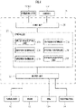
- FIG. 4 illustrates function blocks of the control unit 20.
- an input unit 21 is an interface unit which is connected with the cameras CM and the operation levers 30 and 40.
- the control unit 20 is capable of acquiring the fact of whether the engine is in operation.
- the control unit 20 is capable of accepting operations performed for the operation levers 30 and 40 via the input unit 21. Further, the control unit 20 is capable of acquiring imaged data of images captured by the cameras CM via the input unit 21.
- An output unit 22 sends out drive signals to drive units (not illustrated) of the swivel body 12, the boom 13a, the arm 13b, and the grasping mechanism 14.
- the control unit 20 is, by the drive signals from the output unit 22, capable of causing the swivel body 12, the boom 13a, the arm 13b, and the grasping mechanism 14 to perform the above-described actions.
- a controller 23 is realized with a computer which has a CPU (central processing unit) as an arithmetic processing unit, a ROM (read only memory) as a main storage device, and a RAM (random access memory).
- the CPU reads out a program corresponding to a processing content from the ROM, expands that in the RAM, cooperates with the expanded program, and thereby realizes various kinds of functions.
- An operation accepting unit 23a is capable of accepting input operations by the operation levers 30 and 40.
- the operation accepting unit 23a is capable of acquiring facts that operations for the operation levers 30 and 40 are performed and amounts of the operations via the input unit 21. Consequently, the operation accepting unit 23a is capable of determining whether or not an operation of the operation levers 30 and 40 is performed.
- the operation accepting unit 23a is capable of accepting input operations by the operation buttons 32 and 42.
- the operation accepting unit 23a is capable of acquiring facts that operations for the operation buttons 32 and 42 are performed and amounts of the operations via the input unit 21. Consequently, the operation accepting unit 23a is capable of determining whether or not an operation of the operation buttons 32 and 42 is performed.
- the operation accepting unit 23a is capable of accepting the first to fourth operations about the swiveling action of the swivel body. Specifically, in addition to the first operation for causing the swivel body 12 to swivel, the operation accepting unit 23a is capable of accepting the second operation about the rotating action of the boom 13a of the working arm 13. The operation accepting unit 23a is capable of accepting the third operation about the rotating action of the arm 13b of the working arm 13. The operation accepting unit 23a is capable of accepting the fourth operation about the grasping action of the grasping mechanism 14. Note that the operation accepting unit 23a is capable of acquiring, via the input unit 21, the fact of whether an operation of turning ON or OFF the engine of the drive unit DV of the vehicle dismantling machine 100 is performed.
- a swiveling controller 23b is capable of controlling a rotating action, that is, a swiveling action of the swivel body 12.
- the swiveling controller 23b is capable of causing the swivel body 12 to swivel by driving the drive unit DV based on operations of the operation levers 30 and 40, the operations being accepted by the operation accepting unit 23a. Consequently, the swiveling controller 23b is capable of causing the swivel body 12 to perform a swiveling action in accordance with the amount of the first operation which is accepted by the operation accepting unit 23a.
- a rotation controller 23c is capable of controlling a rotating action of the boom 13a.
- the rotation controller 23c is capable of rotating the boom 13a by driving the drive unit DV based on operations of the operation levers 30 and 40, the operations being accepted by the operation accepting unit 23a. Consequently, the rotation controller 23c is capable of causing the boom 13a of the working arm 13 to perform a rotating action in accordance with the amount of the second operation.
- a rise-fall controller 23d is capable of controlling a rotating action, that is, a rising-falling action of the arm 13b.
- the rise-fall controller 23d is capable of causing the arm 13b to rise and fall by driving the drive unit DV based on operations of the operation levers 30 and 40, the operations being accepted by the operation accepting unit 23a. Consequently, the rise-fall controller 23d is capable of causing the arm 13b of the working arm 13 to perform a rising-falling action, that is, a rotating action in accordance with the amount of the third operation.
- a grasping controller 23e is capable of controlling a rotating action and a grasping action of the grasping mechanism 14.
- the grasping controller 23e is capable of rotating the grasping mechanism 14 or causing the grasping mechanism 14 to perform a grasping action based on operations of the operation buttons 32 and 42, the operations being accepted by the operation accepting unit 23a. Consequently, the grasping controller 23e is capable of causing the grasping mechanism 14 to act in accordance with the amount of the fourth operation.
- a distance acquisition unit 23f is capable of, based on the imaged data of images captured by the cameras CM, for example, acquiring a distance between the grasping mechanism 14 and one region defined based on a position of the vehicle as the work target object.
- the one region may be set as a work region, which is a region in which work is performed by an action of the grasping mechanism 14. In the present embodiment, descriptions will be made while the one region is set as the work region.
- the distance acquisition unit 23f is capable of acquiring the distance from the grasping mechanism 14 to the work region, which is the region in which the vehicle dismantling machine 100 works.
- the distance acquisition unit 23f calculates the distance from the grasping mechanism 14 to the work region based on image processing, for example.
- the work region may be a specific section of a vehicle to be dismantled, for example.
- FIG. 5 illustrates a manner in which the controller 23 controls actions of the swivel body 12.
- a description will be made while the vicinity of a hood of a vehicle OB is set as a work region OA.
- the work region OA is not limited to the vicinity of the hood of the vehicle OB but can appropriately be changed in accordance with embodiments.
- the clamping device 15 is not illustrated in order to make clear a swiveling manner of the swivel body 12.
- the controller 23 is capable of controlling a swiveling amount of the swivel body 12 in accordance with the distance from the grasping mechanism 14 to the work region OA.
- the controller 23 controls the above swiveling amount based on a reference distance D1 to be a reference of the distance to the work region OA in which a process is to be performed by actions of the grasping mechanism 14.
- the controller 23 is capable of controlling the swiveling amount of the swiveling action of the swivel body 12 based on whether or not the distance from the grasping mechanism 14 to the work region OA is longer than the reference distance D1.
- the work region OA may be input by the operator, for example, by a touch panel of a display provided to the driver cab CB. Further, the work region OA may also be acquired from an external apparatus (not illustrated) connected with the control unit 20.
- a processing area PR is a region within the reference distance D1 from a center C of the work region OA.
- a description will be made about a case where a swiveling action of the swivel body 12 is started from a state where the grasping mechanism 14 is present on the outside of the processing area PR, that is, a state where the vehicle dismantling machine 100 is in a posture illustrated by broken lines in FIG. 5 and the swivel body 12 is caused to swivel until the grasping mechanism 14 enters the processing area PR.
- the controller 23 causes the swivel body 12 to swivel while switching modes of the swiveling action of the swivel body 12 in accordance with whether the grasping mechanism 14 is positioned on the outside of the processing area PR or positioned on the inside of the processing area PR, for example. In other words, the controller 23 switches modes of the swiveling action of the swivel body 12 in accordance with whether the grasping mechanism 14 is positioned within the reference distance D1 from the center C of the work region OA or the grasping mechanism 14 is positioned on the outside of the reference distance D1 from the center C of the work region OA.
- the controller 23 causes the swivel body 12 to perform a swiveling action in a displacement mode as a mode of the swiveling action of the swivel body 12.
- the controller 23 causes the swivel body 12 to perform a swiveling action in a work mode as a mode of the swiveling action of the swivel body 12.
- the swivel body 12 is caused to swivel more precisely in the work mode than the displacement mode. That is, in the work mode, the swivel body 12 is caused to swivel in a manner in which a swiveling speed is slower than the displacement mode.
- the swiveling amount of the swivel body 12 is different in accordance with whether or not the distance from the grasping mechanism 14 to the work region OA is the reference distance D1 or less.
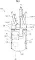
- FIG. 6 illustrates an enlarged front view of the grasping mechanism 14.
- the grasping mechanism 14 has a base portion 14a which is connected with the other end of the arm 13b.
- the base portion 14a is connected with the other end of the arm 13b to be turnable around an axis of the arm 13b. Consequently, the grasping mechanism 14 is rotatable around the axis of the arm 13b.
- the grasping mechanism 14 is rotatable with respect to the arm 13b in accordance with an operation of the operation lever by the operator.
- the grasping mechanism 14 has the pair of claw portions 14b and 14c which are formed into claw shapes. In other words, the grasping mechanism 14 has the pair of claw portions 14b and 14c as gripping members.
- the claw portion 14b is integrally formed with the base portion 14a.
- One end of the claw portion 14c is pivotally supported by a shaft SH of the base portion 14a.
- the claw portion 14c rotates around an axis of the shaft SH, and the respective other ends of the pair of claw portions 14b and 14c thereby approach each other or are separated from each other, that is, a grasping action is capable of being performed.
- the respective other ends of the pair of claw portions 14b and 14c are capable of approaching each other or being separated from each other in accordance with an operation of the operation button 42 by the operator, for example.
- the arrows in FIG. 6 indicate a movable range RM of a claw portion 14c.
- the controller 23 is capable of controlling an action amount of the grasping action of the grasping mechanism 14 in accordance with the distance from the grasping mechanism 14 to the work region OA. Specifically, the controller 23 causes the grasping mechanism 14 to perform grasp while switching modes of the grasping action of the grasping mechanism 14 in accordance with whether the grasping mechanism 14 is positioned on the outside of the processing area PR or positioned on the inside of the processing area PR. In other words, the controller 23 switches modes of the grasping action of the grasping mechanism 14 in accordance with whether the grasping mechanism 14 is positioned within the reference distance D1 from the center C of the work region OA or the grasping mechanism 14 is positioned on the outside of the reference distance D1 from the center C of the work region OA.
- the controller 23 causes the grasping mechanism 14 to perform a grasping action in a displacement mode as a mode of the grasping action of the grasping mechanism 14.
- the controller 23 causes the grasping mechanism 14 to perform a grasping action in a work mode as a mode of the grasping action of the grasping mechanism 14.
- the grasping mechanism 14 is caused to operate more precisely in the work mode than the displacement mode. That is, in the work mode, the grasping mechanism 14 is caused to operate in a manner in which a grasping speed is slower than the displacement mode. Further, a maximum opening is set narrower than the displacement mode such that the grasping mechanism 14 operates suitably for work in a narrow and small space.
- the controller 23 may change modes of the grasping action of the grasping mechanism 14 in accordance with an attribute of the work region. For example, in a step of detaching a harness from the vehicle OB, the grasping mechanism 14 has to be caused to act more precisely than a step of removing the hood from the vehicle. Consequently, for example, in a case where the grasping mechanism 14 is caused to perform a grasping action for an object, for which the grasping mechanism 14 is caused to precisely act, such as a harness (also referred to as precise processing target), the controller 23 may cause the grasping mechanism 14 to act in a fine operation mode for performing a grasping action in a manner in which a grasping action speed is slower than the work mode.
- a harness also referred to as precise processing target
- FIG. 7 illustrates one example of an action processing routine R1 of an object to be operated by the controller 23. Note that a description will be made on the assumption that in FIG. 7 and FIG. 8 , the objects to be operated are the swivel body 12, the boom 13a, the arm 13b, and the grasping mechanism 14.
- the controller 23 determines whether or not the engine of the vehicle dismantling machine 100 is ON (STEP 101). In STEP 101, the controller 23 acquires the fact of whether an operation of turning ON or OFF the engine of the vehicle dismantling machine 100 is performed via the input unit 21, for example. That is, the controller 23 functions as the operation accepting unit 23a.
- the controller 23 determines whether or not the distance from the grasping mechanism 14 to the work region OA is the reference distance D1 or less (STEP 102).
- the determination in STEP 102 is made, for example, based on image data of images captured by the cameras CM and in accordance with whether the grasping mechanism 14 is positioned on the inside of the processing area PR.
- the controller 23 acquires the distance from the grasping mechanism 14 to the work region OA based on the image data. Consequently, the controller 23 functions as the distance acquisition unit 23f which acquires the distance from the grasping mechanism 14 to the work region OA.
- the controller 23 sets a control mode for the object to be operated to the above-described displacement mode (STEP 103).
- the displacement mode is a control mode for performing an action in a manner in which an action speed is faster than the work mode.
- the controller 23 sets the control mode for the object to be operated to the above-described work mode (STEP 104).
- the work mode is a control mode for performing an action in a manner in which an action of the object to be operated is precise and the action speed is faster than the fine operation mode.
- the controller 23 determines whether or not the engine of the vehicle dismantling machine 100 is OFF (STEP 105).
- the controller 23 In a case where it is determined that the engine is ON, that is, the engine is not OFF in the determination in STEP 105 (STEP 105: N), the controller 23 returns to the determination in STEP 102 and repeats subsequent processes.
- FIG. 8 illustrates one example of an output processing routine R2 for the drive unit in each control mode to be executed by each of the swiveling controller 23b to the grasping controller 23e of the controller 23.
- the controller 23 performs an output to the drive unit while making correction, which corresponds to each of the control modes, to an input amount of the first operation to the fourth operation.
- the controller 23 determines whether or not an operation about an action of the object to be operated is accepted (STEP 201). In STEP 201, the controller 23 makes the determination based on whether or not an operation by the operation button 42 is accepted. Consequently, the controller 23 functions as the operation accepting unit 23a.
- the controller 23 determines whether or not the control mode is the work mode (STEP 202).
- the determination about whether or not the control mode is the work mode is made by acquiring a result of a determination process in STEP 102 illustrated in FIG. 7 .
- the controller 23 performs an output to the drive unit while multiplying the operation amount of the operation accepted in STEP 201 by a first correction value defined in advance, that is, performs a first correction output (STEP 203).
- the first correction value is a numerical value which is smaller than one and greater than zero, for example.
- the controller 23 outputs the action amount corresponding to the accepted operation amount to the drive unit of the object to be operated and causes the object to be operated to act. That is, the controller 23 functions as from the swiveling controller 23b to the grasping controller 23e. Consequently, the controller 23 adjusts the action amounts of the objects for action, with respect to the amounts of the first operation to the fourth operation in accordance with the distance from the grasping mechanism 14 to the work region OA.
- the controller 23 In a case where the distance acquisition unit 23f of the controller 23 determines that the control mode is not the work mode in the determination in STEP 202 (STEP 202: N), the controller 23 outputs the operation amount accepted in STEP 201 to the drive unit, that is, performs an output (STEP 204).
- the controller 23 outputs the action amount corresponding to the accepted operation amount to the drive unit of the object to be operated and causes the object to be operated to act. That is, the controller 23 functions as from the swiveling controller 23b to the grasping controller 23e. Consequently, the controller 23 adjusts the action amounts of the objects for action, with respect to the amounts of the first operation to the fourth operation in accordance with the distance from the grasping mechanism 14 to the work region OA.
- the controller 23 determines whether or not the engine of the vehicle dismantling machine 100 is OFF (STEP 205).
- the controller 23 In a case where it is determined that the engine is not OFF in the determination in STEP 205 (STEP 205: N), the controller 23 returns to the determination in STEP 201 and repeats subsequent processes.
- the controller 23 adjusts the action amounts of the objects to be operated, which are caused to act, with respect to the operation amounts of the first operation to the fourth operation in accordance with the distance to the work region OA.
- the objects to be operated whose action amounts are adjusted by the controller 23 are not limited to the swivel body 12, the boom 13a, the arm 13b, or the grasping mechanism 14 but may be the clamping device 15, for example.
- the controller 23 adjusts the action amounts of the objects for action, with respect to the operation amount of the first operation, the amount of the second operation, the amount of the third operation, and the amount of the fourth operation in accordance with the distance to the work region OA. Accordingly, for example, in a case where the distance to the work region OA is long, the actions of the swivel body 12 and so forth can largely and quickly be performed. Further, for example, in a case where the distance to the work region OA is short, the actions of the swivel body 12 and so forth can small and slowly be performed. Consequently, it becomes possible to cause an action object of the vehicle dismantling machine 100 to act in a manner intended by the operator.
- a vehicle dismantling machine 100 according to a second embodiment of the present invention will be described.
- the vehicle dismantling machine 100 according to the second embodiment is different from the vehicle dismantling machine 100 of the first embodiment in the point that the action amount of the object caused to act is adjusted in accordance with a section of the vehicle OB as an object to be dismantled, in other words, an attribute of the work region OA.
- the other points are the same as the vehicle dismantling machine 100 of the first embodiment, and descriptions thereof will thus not be made.
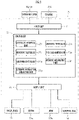
- FIG. 9 illustrates function blocks of the control unit 20 of the vehicle dismantling machine 100 of the second embodiment. As illustrated in FIG. 9 , the control unit 20 of the second embodiment is different from the control unit 20 of the first embodiment in the point that the controller 23 has an attribute information acquisition unit 23g.
- the attribute information acquisition unit 23g is capable of acquiring attribute information of the work region OA such as the vicinity of the hood, the vicinity of a door, or a bottom surface side of the vehicle OB, for example, based on imaged data of image captured by the cameras CM, for example. Consequently, the attribute information acquisition unit 23g is capable of acquiring the attribute information of the work region OA.
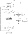
- FIG. 10 illustrates one example of an action processing routine R3 of the object to be operated by the controller 23. Note that a description will be made on the assumption that in FIG. 10 and FIG. 11 , the objects to be operated are the swivel body 12, the boom 13a, the arm 13b, and the grasping mechanism 14.
- the controller 23 determines whether or not the engine of the vehicle dismantling machine 100 is ON (STEP 301). In STEP 301, the controller 23 acquires the fact of whether an operation of turning ON or OFF the engine of the vehicle dismantling machine 100 is performed via the input unit 21, for example. That is, the controller 23 functions as the operation accepting unit 23a.
- the controller 23 determines whether or not the distance from the grasping mechanism 14 to the work region OA is the reference distance D1 or less (STEP 302).
- the determination in STEP 302 is made, for example, based on image data of images captured by the cameras CM and in accordance with whether the grasping mechanism 14 is positioned on the inside of the processing area PR.
- the controller 23 acquires the distance from the grasping mechanism 14 to the work region OA based on the image data. Consequently, the controller 23 functions as the distance acquisition unit 23f which acquires the distance from the grasping mechanism 14 to the work region OA.
- the controller 23 sets the control mode for the object to be operated to the above-described displacement mode (STEP 303).
- the displacement mode is a control mode for performing an action in a manner in which the action speed is faster than the work mode.
- the controller 23 determines whether or not the attribute of the work region OA is the precise processing target (STEP 304).
- the determination about whether or not the attribute of the work region OA is the precise processing target may be performed based on input information input by the operator by a touch panel of a display provided to the driver cab CB, for example, as described above or may be performed based on information acquired from an external apparatus (not illustrated) connected with the control unit 20.
- the work region OA may be acquired based on the imaged data of image captured by the cameras CM as described below.
- the controller 23 acquires plural sets of imaged data of images captured by the cameras CM in each regular time period, for example. By image processing, the controller 23 assesses to which section of the vehicle OB the grasping mechanism 14 is moving based on the plural sets of imaged data.
- the controller 23 acquires the attribute information while setting a section of the vehicle OB, the section being positioned in a moving direction of the grasping mechanism 14, as the attribute of the work region OA.
- the grasping mechanism 14 gradually moves toward the hood.
- the controller 23 is capable of, by image processing, assessing that the grasping mechanism 14 is moving to the hood of the vehicle OB based on the plural sets of imaged data of images captured in each regular time period.
- the controller 23 acquires the attribute information while setting the hood of the vehicle OB as the attribute of the work region OA. Consequently, the controller 23 functions as the attribute information acquisition unit 23g.
- the controller 23 sets the control mode for the object to be operated to the above-described fine operation mode (STEP 305).
- the fine operation mode is a control mode for performing an action in a manner in which an action of the object to be operated is precise and the action speed is slower than the work mode.
- the controller 23 sets the control mode for the object to be operated to the above-described work mode (STEP 306).
- the work mode is a control mode for performing an action in a manner in which an action of the object to be operated is precise and the action speed is faster than the fine operation mode.
- the controller 23 determines whether or not the engine of the vehicle dismantling machine 100 is OFF (STEP 307).
- the controller 23 In a case where it is determined that the engine is not OFF in the determination in STEP 307 (STEP 307: N), the controller 23 returns to the determination in STEP 302 and repeats subsequent processes.
- the controller 23 adjusts the action amounts of the objects to be operated, which are caused to act, with respect to the operation amounts of the first operation to the fourth operation in accordance with the distance to the work region OA.
- the objects to be operated whose action amounts are adjusted by the controller 23 are not limited to the swivel body 12, the boom 13a, the arm 13b, or the grasping mechanism 14 but may be the clamping device 15, for example.
- FIG. 11 illustrates one example of an output processing routine R4 for the drive unit in each control mode to be executed by each of the swiveling controller 23b to the grasping controller 23e of the controller 23.
- the controller 23 performs an output to the drive unit while making correction, which corresponds to the displacement mode, the work mode, or the fine operation mode, to an input amount of the first operation to the fourth operation.
- the controller 23 determines whether or not an operation about an action of the object to be operated is accepted (STEP 401). In STEP 401, the controller 23 makes the determination based on whether or not an operation by the operation button 42 is accepted. Consequently, the controller 23 functions as the operation accepting unit 23a.
- the controller 23 determines whether or not the control mode is the work mode (STEP 402).
- the determination about whether or not the control mode is the work mode is made by acquiring a result of a determination process in STEP 304 illustrated in FIG. 10 .
- the controller 23 performs an output to the drive unit while multiplying the operation amount of the operation accepted in STEP 401 by a first correction value defined in advance, that is, performs a first correction output (STEP 403).
- the first correction value is a numerical value which is smaller than one and greater than zero, for example.
- the controller 23 outputs the action amount corresponding to the accepted operation amount to the drive unit of the object to be operated and causes the object to be operated to act. That is, the controller 23 functions as from the swiveling controller 23b to the grasping controller 23e. Consequently, the controller 23 adjusts the action amounts of the objects for action, with respect to the amounts of the first operation to the fourth operation in accordance with the attribute of the work region OA.
- the distance acquisition unit 23f of the controller 23 determines whether or not the control mode is the fine operation mode (STEP 404).
- the determination about whether or not the control mode is the fine operation mode is made by acquiring a result of a determination process in STEP 304 illustrated in FIG. 10 .
- the controller 23 determines that the control mode is the fine operation mode in the determination in STEP 404 (STEP 404: Y)
- the controller 23 performs an output to the drive unit while multiplying the operation amount accepted in STEP 401 by a second correction value defined in advance, that is, performs a second correction output (STEP 405).
- the second correction value is a numerical value which is smaller than one and greater than zero and is a numerical value which is smaller than the first correction value, for example.
- the controller 23 outputs the action amount corresponding to the accepted operation amount to the drive unit of the object to be operated and causes the object to be operated to act. That is, the controller 23 functions as from the swiveling controller 23b to the grasping controller 23e.
- the controller 23 adjusts the action amounts of the objects for action, with respect to the amounts of the first operation to the fourth operation in accordance with the attribute of the work region OA.
- the controller 23 determines that the control mode is not the fine operation mode in the determination in STEP 404 (STEP 404: N)
- the controller 23 outputs the operation amount accepted in STEP 401 to the drive unit, that is, performs an output (STEP 406).
- the controller 23 outputs the action amount corresponding to the accepted operation amount to the drive unit of the object to be operated and causes the object to be operated to act. That is, the controller 23 functions as from the swiveling controller 23b to the grasping controller 23e.
- the controller 23 adjusts the action amounts of the objects for action, with respect to the amounts of the first operation to the fourth operation in accordance with the attribute of the work region OA.
- the controller 23 determines whether or not the engine of the vehicle dismantling machine 100 is OFF (STEP 407).
- the controller 23 In a case where it is determined that the engine is not OFF in the determination in STEP 407 (STEP 407: N), the controller 23 returns to the determination in STEP 401 and repeats subsequent processes.
- the objects whose action amounts are changed by the controller 23 are not limited to the swivel body 12, the boom 13a, the arm 13b, or the grasping mechanism 14 but may be the clamping device 15, for example.
- the working unit is set as the grasping mechanism 14.
- the working unit is not limited to the grasping mechanism 14 but may be a bucket used for an excavator, for example.
- the working machine is set as the vehicle dismantling machine 100.
- the working machine may be used not only for the vehicle dismantling machine 100 but also for machines such as a construction demolition machine, a hydraulic shovel, and a scrap loader, for example.
- the grasping mechanism 14 has to be caused to act more finely than a step of removing a hood from the vehicle.
- the controller 23 adjusts the action amounts of the objects for action, with respect to the amount of the first operation, the amount of the second operation, the amount of the third operation, and the amount of the fourth operation in accordance with the attribute of the work region OA, in other words, in accordance with whether a target of work is tearing of the hood of the vehicle OB or detachment of the harness, for example, and the vehicle dismantling machine 100 thereby adjusts the action amounts of the objects for action. Consequently, it becomes possible to adjust the action amount of the object for action, in accordance with the work intended by the operator.
- the controller 23 adjusts a displacement amount or an action amount of a processing action of the grasping mechanism 14 with respect to the operation amount in accordance with a distance between the grasping mechanism 14 (working unit) and one region. Accordingly, for example, in a case where the distance is long, the grasping mechanism 14 can be caused to quickly act while its displacement amount is made large. Further, for example, in a case where the distance is short, the grasping mechanism 14 can be caused to slowly act while its displacement amount is made small. Consequently, it becomes possible to cause the grasping mechanism 14 to be displaced or to act in a manner intended by the operator.
- the one region is the work region OA as a region in which work is performed by an action of the grasping mechanism 14.
- the one region is the work region OA
- the controller 23 thereby adjusts the displacement amount or the action amount of the processing action of the grasping mechanism 14 with respect to the operation amount in accordance with the distance from the grasping mechanism 14 to the region where work is performed, that is, the distance to the work region OA. Consequently, it becomes possible to cause the grasping mechanism 14 to be displaced or to act in a manner corresponding to work to be performed by the operator.
- the work machine has the attribute information acquisition unit 23g which acquires the attribute information indicating the attribute of a process to be performed in the one region, and the controller 23 adjusts the displacement amount or the action amount of the grasping mechanism 14 with respect to the operation amount in accordance with the attribute information of the one region.
- the controller 23 adjusts the displacement amount or the action amount of the grasping mechanism 14 in accordance with the attribute information of the work region OA, in other words, in accordance with whether a target of work is tearing of the hood of the vehicle OB or detachment of the harness, for example. Consequently, it becomes possible to adjust the action amount of the object for action, in accordance with the work intended by the operator.
- the work machine includes the swivel body 12 which is swivelable with respect to the traveling body 11 and the working arm 13 that has the boom 13a (first arm portion) whose one end is rotatably coupled with the swivel body 12 and the arm 13b (second arm portion) whose one end is coupled with the other end of the boom 13a rotatably with respect to the boom 13a and whose other end is coupled with the grasping mechanism 14.
- the operation accepting unit 23a accepts the first operation about the swiveling action of the swivel body 12, the second operation about the rotating action of the boom 13a of the working arm 13, the third operation about the rotating action of the arm 13b of the working arm 13, or the fourth operation about the action of the grasping mechanism 14.
- the controller 23 causes the swivel body 12 to perform the swiveling action by the swiveling amount corresponding to the operation amount of the first operation accepted by the operation accepting unit 23a, causes the boom 13a of the working arm 13 to perform the rotating action by a first rotation amount corresponding to the operation amount of the second operation, causes the arm 13b of the working arm 13 to perform the rotating action by a second rotation amount corresponding to the operation amount of the third operation, causes the grasping mechanism 14 to perform the action by the action amount corresponding to the operation amount of the fourth operation, and adjusts the swiveling amount with respect to the operation amount of the first operation, the first rotation amount with respect to the operation amount of the second operation, the second rotation amount with respect to the operation amount of the third operation, or the action amount with respect to the operation amount of the fourth operation in accordance with the distance to the one region.
- the controller 23 adjusts the swiveling amount with respect to the operation amount of the first operation, the first rotation amount with respect to the operation amount of the second operation, the second rotation amount with respect to the operation amount of the third operation, or the action amount with respect to the operation amount of the fourth operation in accordance with the distance to the one region. Consequently, it is possible to perform minute adjustment by adjusting the action amount or the like of each of the objects caused to act, and it becomes possible to cause the object to perform the action corresponding to an intention of the operator.
- the grasping mechanism 14 has the base portion connected with the arm 13b and the pair of claw portions 14b and 14c (gripping members) which are pivotally supported by the base portion and are capable of pinching and retaining an object by an opening-closing action, and the controller 23 causes the grasping mechanism 14 to act in plural work action modes among which an opening-closing action amount of the pair of claw portions 14b and 14c with respect to the operation amount of the fourth operation is different.
- the controller 23 adjusts the action amount of the grasping mechanism 14 and can thereby cause the pair of claw portions 14b and 14c of the grasping mechanism 14 to perform a proper action corresponding to a work step.
- the grasping mechanism 14 it is possible to cause the grasping mechanism 14 to more minutely act than work needing a large action such as removing the hood from the vehicle OB.
- the controller 23 may cause the swivel body 12 to swivel in plural work action modes among which the swiveling amount of the swivel body 12 with respect to the operation amount of the first operation is mutually different. In such a manner, it becomes possible to cause the swivel body 12 to swivel, that is, cause the grasping mechanism 14 to be displaced in a manner intended by the operator.
Landscapes
- Engineering & Computer Science (AREA)
- Structural Engineering (AREA)
- Mining & Mineral Resources (AREA)
- Civil Engineering (AREA)
- General Engineering & Computer Science (AREA)
- Mechanical Engineering (AREA)
- Operation Control Of Excavators (AREA)
- Crushing And Grinding (AREA)
Abstract
Description
- The present invention relates to a work machine such as a hydraulic excavator or a dismantling work machine dismantling a vehicle.
- For example, in a hydraulic excavator, an upper swivel body including an operator cab or the like is laid on a lower traveling body to be swivelable by a swivel device. One end of a boom is rotatably coupled with a front portion of the upper swivel body. One end of an arm is rotatably coupled with another end of the boom. A bucket is rotatably coupled with another end of the arm.
- A swiveling action of the upper swivel body and rotating actions of the boom, the arm, and the bucket are performed by operations, by an operator, of operation levers provided to the operator cab, for example.
- In a case of ground leveling work or the like, precision of actions of the boom, the arm, and the bucket are requested. Accordingly,
Patent Literature 1 discloses that switches for adjusting speeds of rotating actions of the boom, the arm, and the bucket are provided to the operation levers (see Patent Literature 1). - Patent Literature 1:
Japanese Patent Laid-Open No. 2000-284849 - In an operation control method disclosed in
Patent Literature 1, an operator has to adjust speeds of rotating actions of a boom, an arm, and a bucket by manually operating switches. Consequently, for example, one problem may be raised that in a case where the operator makes wrong switching of the switch, an action can be performed at a speed not intended by the operator. - An object of the present invention, which has been made in consideration of the above problems in related art, is to provide a work machine that is capable of causing an action object of the work machine to act in a manner intended by an operator.
- A work machine of the present invention is a work machine for processing a work target object, the work machine including: a base body; a working unit which is displaceable with respect to the base body and performs a processing action on the work target object; an operation accepting unit which accepts an operation for the working unit; a controller which controls displacement and the processing action of the working unit in accordance with an operation accepted by the operation accepting unit and an operation amount of the operation; and a distance acquisition unit which acquires a distance between the working unit and one region defined based on a position of the work target object, in which the controller adjusts a displacement amount or an action amount of the processing action of the working unit with respect to the operation amount in accordance with the distance.
-
-
FIG. 1 is a side view of a work machine according to a first embodiment. -
FIG. 2 is a plan view of the work machine according to the first embodiment. -
FIG. 3 is a perspective view of an operation lever inFIG. 2 . -
FIG. 4 is a block diagram illustrating function blocks of the work machine according to the first embodiment. -
FIG. 5 is an explanatory diagram illustrating a control manner of the work machine by a controller inFIG. 4 . -
FIG. 6 is an enlarged front view of a grasping mechanism inFIG. 1 . -
FIG. 7 is a flowchart illustrating an action processing routine of the work machine according to the first embodiment. -
FIG. 8 is a flowchart illustrating an output processing routine of the work machine according to the first embodiment. -
FIG. 9 is a block diagram illustrating function blocks of a work machine according to a second embodiment. -
FIG. 10 is a flowchart illustrating an action processing routine of the work machine according to the second embodiment. -
FIG. 11 is a flowchart illustrating an output processing routine of the work machine according to the second embodiment. - Embodiments of the present invention will hereinafter be described in detail with reference to drawings. However, those may appropriately be altered and combined. Further, in the following descriptions and the attached drawings, descriptions will be made while giving the same reference characters to substantially the same or equivalent portions.
-
FIG. 1 is a side view of avehicle dismantling machine 100 as a work machine according to a first embodiment. Note that the arrows inFIG. 1 indicate an up-down direction and a front-rear direction of thevehicle dismantling machine 100. Thevehicle dismantling machine 100 as the work machine is a machine that dismantles a scrapped vehicle as a work target object into each component, for example. - As illustrated in
FIG. 1 , thevehicle dismantling machine 100 has atraveling body 11 as a base body. The travelingbody 11 is of a crawler type and causes thevehicle dismantling machine 100 to move forward or rearward. - A
swivel body 12 is provided on thetraveling body 11 to be swivelable with respect to thetraveling body 11. Theswivel body 12 is provided to be swivelable in a direction around a swivel axis CX with respect to thetraveling body 11. - A drive unit DV is provided to the
swivel body 12. The drive unit DV includes a swiveling motor (not illustrated) which is capable of causing theswivel body 12 to swivel with respect to thetraveling body 11. For example, the swiveling motor is driven by hydraulic oil from a hydraulic pressure generation device (not illustrated) which includes a hydraulic pressure pump to be driven by a driving force of an engine (not illustrated), causing theswivel body 12 to swivel. - A driver cab CB is disposed in a front side portion of the
swivel body 12 in the front-rear direction of the vehicle dismantling machine 100 (the front-rear direction of the arrows inFIG. 1 ). In the driver cab CB, two operation levers (not illustrated) are provided by which the operator is capable of operating actions such as swiveling of theswivel body 12. Further, in the driver cab CB, a display (not illustrated) is provided which displays a control state of a swiveling action of theswivel body 12. - A
boom 13a as a first arm portion is formed into a rod shape. One end of theboom 13a is connected with a front side of theswivel body 12 to be rotatable with respect to theswivel body 12, that is, to be capable of rising and falling. Theboom 13a is rotatable with respect to theswivel body 12 in accordance with an operation of the operation lever by the operator. - One end of a rod-
shaped arm 13b as a second arm portion is connected with another end of theboom 13a to be rotatable, that is, to be capable of rising and falling with respect to theboom 13a. Thearm 13b is rotatable with respect to theboom 13a in accordance with an operation of the operation lever by the operator. A workingarm 13 is made up of theboom 13a and thearm 13b. - A
grasping mechanism 14 as a working unit is connected with another end of thearm 13b to be rotatable, that is, to be capable of rising and falling with respect to thearm 13b. Thegrasping mechanism 14 is rotatable with respect to thearm 13b in accordance with an operation of the operation lever by the operator. Thegrasping mechanism 14 is capable of making a grasping action for the vehicle as the work target object. As described above, thegrasping mechanism 14 is displaceable with respect to thetraveling body 11 and is capable of performing a processing action on the vehicle, that is, a grasping action. - A
clamping device 15 has anarm support portion 15a which is provided to a front portion of thetraveling body 11. Thearm support portion 15a is connected with thetraveling body 11. - The
clamping device 15 has a pair of left and right pressingarms 15b which are supported by thearm support portion 15a. Theclamping device 15 is capable of rising and falling in the up-down direction, that is, of rotating with respect to thetraveling body 11. - Cameras CM are mounted on a total of four parts such that one camera is mounted on each of both sides in front and rear portions of the
swivel body 12. Each of the cameras CM captures an image, and thevehicle dismantling machine 100 is thereby capable of acquiring videos or images on both sides in its front and rear portions. -
FIG. 2 illustrates an upper surface of thevehicle dismantling machine 100. As illustrated inFIG. 2 , theswivel body 12 is capable of swiveling around a swiveling center as the center. Acontrol unit 20 controls a swiveling action of theswivel body 12, rotating actions of theboom 13a and thearm 13b, an action of the graspingmechanism 14, and so forth. Thecontrol unit 20 is provided to theswivel body 12. Thecontrol unit 20 is connected with the cameras CM to be capable of receiving imaged information from the cameras CM. Thecontrol unit 20 is capable of performing the control of the above swiveling action and so forth of thevehicle dismantling machine 100 based on the imaged information of the cameras CM. - In the driver cab CB, a seat ST is provided on which the operator is capable of being seated. Further, in the driver cab CB, an
operation lever 30 is provided on a left side when seen from the seat ST. Further, in the driver cab CB, anoperation lever 40 is provided on a right side when seen from the seat ST. The operator operates the operation levers 30 and 40 and can thereby cause theswivel body 12 to perform a swiveling action, for example. -
FIG. 3 illustrates the operation lever. As illustrated inFIG. 3 , the operation levers 30 and 40 have base portions BS and rod-shapedshafts shafts shafts shafts - When the
shaft 31 is inclined in the left-right direction by the operator, for example, by control by thecontrol unit 20, theswivel body 12 is caused to rotate, that is, swivel with respect to the travelingbody 11. Specifically, when theshaft 31 is inclined rightward by the operator, theswivel body 12 is caused to swivel in a right-hand direction. When theshaft 31 is inclined leftward by the operator, theswivel body 12 is caused to swivel in a left-hand direction. An operation of theoperation lever 30 for causing theswivel body 12 with respect to the travelingbody 11 as described above will be denoted as a first operation. - When the
shaft 41 is inclined in the front-rear direction by the operator, for example, by control by thecontrol unit 20, theboom 13a is rotated with respect to theswivel body 12. Specifically, when theshaft 41 is inclined forward by the operator, theboom 13a is pushed out forward. When theshaft 41 is inclined rearward by the operator, theboom 13a is pulled rearward. An operation of theoperation lever 40 for rotating theboom 13a with respect to theswivel body 12 as described above will be denoted as a second operation. - When the
shaft 31 is inclined in the front-rear direction by the operator, for example, by control by thecontrol unit 20, thearm 13b is rotated with respect to theboom 13a. Specifically, when theshaft 31 is inclined forward by the operator, thearm 13b is pushed out forward. When theshaft 31 is inclined rearward by the operator, thearm 13b is pulled rearward. An operation of theoperation lever 30 for rotating thearm 13b with respect to theboom 13a as described above will be denoted as a third operation. - When the
shaft 41 is inclined in the left-right direction by the operator, for example, by control by thecontrol unit 20, the graspingmechanism 14 is rotated with respect to thearm 13b. Specifically, when theshaft 41 is inclined rightward by the operator, the graspingmechanism 14 is pushed out forward. When theshaft 41 is inclined rearward by the operator, the graspingmechanism 14 is pulled rearward. - The
shafts operation buttons - The
operation buttons base bodies Button portions base bodies operation buttons shafts base bodies operation buttons - When the
operation button 32 is inclined in the left-right direction by the operator, for example, by control by thecontrol unit 20, the graspingmechanism 14 is rotated with respect to thearm 13b. Specifically, when theoperation button 32 is inclined rightward by the operator, the graspingmechanism 14 is rotated in the right-hand direction. When theoperation button 32 is inclined leftward by the operator, the graspingmechanism 14 is rotated in the left-hand direction. - When the
operation button 42 is inclined in the left-right direction by the operator, for example, by control by thecontrol unit 20, a pair ofclaw portions mechanism 14 are caused to open or close. Specifically, when theoperation button 42 is inclined rightward by the operator, the pair ofclaw portions mechanism 14 are separated from each other, that is, theclaw portion 14b is opened. When theoperation button 42 is inclined leftward by the operator, the pair ofclaw portions mechanism 14 are caused to approach each other, that is, theclaw portion 14b is closed. An operation of theoperation button 42 for causing the pair ofclaw portions mechanism 14 to open and close, that is, for causing grasping as described above will be denoted as a fourth operation. -
FIG. 4 illustrates function blocks of thecontrol unit 20. As illustrated inFIG. 4 , aninput unit 21 is an interface unit which is connected with the cameras CM and the operation levers 30 and 40. Note that thecontrol unit 20 is capable of acquiring the fact of whether the engine is in operation. - The
control unit 20 is capable of accepting operations performed for the operation levers 30 and 40 via theinput unit 21. Further, thecontrol unit 20 is capable of acquiring imaged data of images captured by the cameras CM via theinput unit 21. - An
output unit 22 sends out drive signals to drive units (not illustrated) of theswivel body 12, theboom 13a, thearm 13b, and the graspingmechanism 14. Thecontrol unit 20 is, by the drive signals from theoutput unit 22, capable of causing theswivel body 12, theboom 13a, thearm 13b, and the graspingmechanism 14 to perform the above-described actions. - A
controller 23 is realized with a computer which has a CPU (central processing unit) as an arithmetic processing unit, a ROM (read only memory) as a main storage device, and a RAM (random access memory). The CPU reads out a program corresponding to a processing content from the ROM, expands that in the RAM, cooperates with the expanded program, and thereby realizes various kinds of functions. - An
operation accepting unit 23a is capable of accepting input operations by the operation levers 30 and 40. Theoperation accepting unit 23a is capable of acquiring facts that operations for the operation levers 30 and 40 are performed and amounts of the operations via theinput unit 21. Consequently, theoperation accepting unit 23a is capable of determining whether or not an operation of the operation levers 30 and 40 is performed. - Further, the
operation accepting unit 23a is capable of accepting input operations by theoperation buttons operation accepting unit 23a is capable of acquiring facts that operations for theoperation buttons input unit 21. Consequently, theoperation accepting unit 23a is capable of determining whether or not an operation of theoperation buttons - As described above, the
operation accepting unit 23a is capable of accepting the first to fourth operations about the swiveling action of the swivel body. Specifically, in addition to the first operation for causing theswivel body 12 to swivel, theoperation accepting unit 23a is capable of accepting the second operation about the rotating action of theboom 13a of the workingarm 13. Theoperation accepting unit 23a is capable of accepting the third operation about the rotating action of thearm 13b of the workingarm 13. Theoperation accepting unit 23a is capable of accepting the fourth operation about the grasping action of the graspingmechanism 14. Note that theoperation accepting unit 23a is capable of acquiring, via theinput unit 21, the fact of whether an operation of turning ON or OFF the engine of the drive unit DV of thevehicle dismantling machine 100 is performed. - A swiveling
controller 23b is capable of controlling a rotating action, that is, a swiveling action of theswivel body 12. The swivelingcontroller 23b is capable of causing theswivel body 12 to swivel by driving the drive unit DV based on operations of the operation levers 30 and 40, the operations being accepted by theoperation accepting unit 23a. Consequently, the swivelingcontroller 23b is capable of causing theswivel body 12 to perform a swiveling action in accordance with the amount of the first operation which is accepted by theoperation accepting unit 23a. - A
rotation controller 23c is capable of controlling a rotating action of theboom 13a. Therotation controller 23c is capable of rotating theboom 13a by driving the drive unit DV based on operations of the operation levers 30 and 40, the operations being accepted by theoperation accepting unit 23a. Consequently, therotation controller 23c is capable of causing theboom 13a of the workingarm 13 to perform a rotating action in accordance with the amount of the second operation. - A rise-
fall controller 23d is capable of controlling a rotating action, that is, a rising-falling action of thearm 13b. The rise-fall controller 23d is capable of causing thearm 13b to rise and fall by driving the drive unit DV based on operations of the operation levers 30 and 40, the operations being accepted by theoperation accepting unit 23a. Consequently, the rise-fall controller 23d is capable of causing thearm 13b of the workingarm 13 to perform a rising-falling action, that is, a rotating action in accordance with the amount of the third operation. - A grasping
controller 23e is capable of controlling a rotating action and a grasping action of the graspingmechanism 14. The graspingcontroller 23e is capable of rotating the graspingmechanism 14 or causing the graspingmechanism 14 to perform a grasping action based on operations of theoperation buttons operation accepting unit 23a. Consequently, the graspingcontroller 23e is capable of causing the graspingmechanism 14 to act in accordance with the amount of the fourth operation. - A
distance acquisition unit 23f is capable of, based on the imaged data of images captured by the cameras CM, for example, acquiring a distance between the graspingmechanism 14 and one region defined based on a position of the vehicle as the work target object. Note that the one region may be set as a work region, which is a region in which work is performed by an action of the graspingmechanism 14. In the present embodiment, descriptions will be made while the one region is set as the work region. - As described above, the
distance acquisition unit 23f is capable of acquiring the distance from the graspingmechanism 14 to the work region, which is the region in which thevehicle dismantling machine 100 works. - The
distance acquisition unit 23f calculates the distance from the graspingmechanism 14 to the work region based on image processing, for example. The work region may be a specific section of a vehicle to be dismantled, for example. -
FIG. 5 illustrates a manner in which thecontroller 23 controls actions of theswivel body 12. InFIG. 5 , a description will be made while the vicinity of a hood of a vehicle OB is set as a work region OA. Note that the work region OA is not limited to the vicinity of the hood of the vehicle OB but can appropriately be changed in accordance with embodiments. Further, inFIG. 5 , the clampingdevice 15 is not illustrated in order to make clear a swiveling manner of theswivel body 12. - The
controller 23 is capable of controlling a swiveling amount of theswivel body 12 in accordance with the distance from the graspingmechanism 14 to the work region OA. For example, thecontroller 23 controls the above swiveling amount based on a reference distance D1 to be a reference of the distance to the work region OA in which a process is to be performed by actions of the graspingmechanism 14. In this case, thecontroller 23 is capable of controlling the swiveling amount of the swiveling action of theswivel body 12 based on whether or not the distance from the graspingmechanism 14 to the work region OA is longer than the reference distance D1. - Note that the work region OA may be input by the operator, for example, by a touch panel of a display provided to the driver cab CB. Further, the work region OA may also be acquired from an external apparatus (not illustrated) connected with the
control unit 20. - As illustrated in
FIG. 5 , a processing area PR is a region within the reference distance D1 from a center C of the work region OA. A description will be made about a case where a swiveling action of theswivel body 12 is started from a state where the graspingmechanism 14 is present on the outside of the processing area PR, that is, a state where thevehicle dismantling machine 100 is in a posture illustrated by broken lines inFIG. 5 and theswivel body 12 is caused to swivel until the graspingmechanism 14 enters the processing area PR. - The
controller 23 causes theswivel body 12 to swivel while switching modes of the swiveling action of theswivel body 12 in accordance with whether the graspingmechanism 14 is positioned on the outside of the processing area PR or positioned on the inside of the processing area PR, for example. In other words, thecontroller 23 switches modes of the swiveling action of theswivel body 12 in accordance with whether the graspingmechanism 14 is positioned within the reference distance D1 from the center C of the work region OA or the graspingmechanism 14 is positioned on the outside of the reference distance D1 from the center C of the work region OA. - On the outside of the processing area PR, the
controller 23 causes theswivel body 12 to perform a swiveling action in a displacement mode as a mode of the swiveling action of theswivel body 12. When the graspingmechanism 14 enters the processing area PR, thecontroller 23 causes theswivel body 12 to perform a swiveling action in a work mode as a mode of the swiveling action of theswivel body 12. - In a case where the
operation lever 30 is operated by the same operation amount in the displacement mode and the work mode, theswivel body 12 is caused to swivel more precisely in the work mode than the displacement mode. That is, in the work mode, theswivel body 12 is caused to swivel in a manner in which a swiveling speed is slower than the displacement mode. - As described above, even when the operation amount of the
operation lever 30 is the same, the swiveling amount of theswivel body 12 is different in accordance with whether or not the distance from the graspingmechanism 14 to the work region OA is the reference distance D1 or less. -
FIG. 6 illustrates an enlarged front view of the graspingmechanism 14. As illustrated inFIG. 6 , the graspingmechanism 14 has abase portion 14a which is connected with the other end of thearm 13b. Specifically, thebase portion 14a is connected with the other end of thearm 13b to be turnable around an axis of thearm 13b. Consequently, the graspingmechanism 14 is rotatable around the axis of thearm 13b. The graspingmechanism 14 is rotatable with respect to thearm 13b in accordance with an operation of the operation lever by the operator. - The grasping
mechanism 14 has the pair ofclaw portions mechanism 14 has the pair ofclaw portions claw portion 14b is integrally formed with thebase portion 14a. One end of theclaw portion 14c is pivotally supported by a shaft SH of thebase portion 14a. - Consequently, the
claw portion 14c rotates around an axis of the shaft SH, and the respective other ends of the pair ofclaw portions claw portions operation button 42 by the operator, for example. Note that the arrows inFIG. 6 indicate a movable range RM of aclaw portion 14c. - The
controller 23 is capable of controlling an action amount of the grasping action of the graspingmechanism 14 in accordance with the distance from the graspingmechanism 14 to the work region OA. Specifically, thecontroller 23 causes the graspingmechanism 14 to perform grasp while switching modes of the grasping action of the graspingmechanism 14 in accordance with whether the graspingmechanism 14 is positioned on the outside of the processing area PR or positioned on the inside of the processing area PR. In other words, thecontroller 23 switches modes of the grasping action of the graspingmechanism 14 in accordance with whether the graspingmechanism 14 is positioned within the reference distance D1 from the center C of the work region OA or the graspingmechanism 14 is positioned on the outside of the reference distance D1 from the center C of the work region OA. - On the outside of the processing area PR, the
controller 23 causes the graspingmechanism 14 to perform a grasping action in a displacement mode as a mode of the grasping action of the graspingmechanism 14. When the graspingmechanism 14 enters the processing area PR, thecontroller 23 causes the graspingmechanism 14 to perform a grasping action in a work mode as a mode of the grasping action of the graspingmechanism 14. - In a case where the
operation lever 30 is operated by the same operation amount in the displacement mode and the work mode, the graspingmechanism 14 is caused to operate more precisely in the work mode than the displacement mode. That is, in the work mode, the graspingmechanism 14 is caused to operate in a manner in which a grasping speed is slower than the displacement mode. Further, a maximum opening is set narrower than the displacement mode such that the graspingmechanism 14 operates suitably for work in a narrow and small space. - Further, the
controller 23 may change modes of the grasping action of the graspingmechanism 14 in accordance with an attribute of the work region. For example, in a step of detaching a harness from the vehicle OB, the graspingmechanism 14 has to be caused to act more precisely than a step of removing the hood from the vehicle. Consequently, for example, in a case where the graspingmechanism 14 is caused to perform a grasping action for an object, for which the graspingmechanism 14 is caused to precisely act, such as a harness (also referred to as precise processing target), thecontroller 23 may cause the graspingmechanism 14 to act in a fine operation mode for performing a grasping action in a manner in which a grasping action speed is slower than the work mode. -
FIG. 7 illustrates one example of an action processing routine R1 of an object to be operated by thecontroller 23. Note that a description will be made on the assumption that inFIG. 7 andFIG. 8 , the objects to be operated are theswivel body 12, theboom 13a, thearm 13b, and the graspingmechanism 14. - As illustrated in
FIG. 7 , thecontroller 23 determines whether or not the engine of thevehicle dismantling machine 100 is ON (STEP 101). InSTEP 101, thecontroller 23 acquires the fact of whether an operation of turning ON or OFF the engine of thevehicle dismantling machine 100 is performed via theinput unit 21, for example. That is, thecontroller 23 functions as theoperation accepting unit 23a. - In a case where it is determined that the engine is not ON in the determination in STEP 101 (STEP 101: N), the
controller 23 finishes the process. - In a case where it is determined that the engine is ON in the determination in STEP 101 (STEP 101: Y), the
controller 23 determines whether or not the distance from the graspingmechanism 14 to the work region OA is the reference distance D1 or less (STEP 102). - The determination in
STEP 102 is made, for example, based on image data of images captured by the cameras CM and in accordance with whether the graspingmechanism 14 is positioned on the inside of the processing area PR. In other words, thecontroller 23 acquires the distance from the graspingmechanism 14 to the work region OA based on the image data. Consequently, thecontroller 23 functions as thedistance acquisition unit 23f which acquires the distance from the graspingmechanism 14 to the work region OA. - In a case where the
distance acquisition unit 23f of thecontroller 23 determines, in the determination inSTEP 102, that the distance is longer than the reference distance D1, that is, not the reference distance D1 or less (STEP 102: N), thecontroller 23 sets a control mode for the object to be operated to the above-described displacement mode (STEP 103). Note that as described above, the displacement mode is a control mode for performing an action in a manner in which an action speed is faster than the work mode. - In a case where it is determined that the distance is the reference distance D1 or less in the determination in STEP 102 (STEP 102: Y), the
controller 23 sets the control mode for the object to be operated to the above-described work mode (STEP 104). Note that as described above, the work mode is a control mode for performing an action in a manner in which an action of the object to be operated is precise and the action speed is faster than the fine operation mode. - After
STEP 103 orSTEP 104, thecontroller 23 determines whether or not the engine of thevehicle dismantling machine 100 is OFF (STEP 105). - In a case where it is determined that the engine is ON, that is, the engine is not OFF in the determination in STEP 105 (STEP 105: N), the
controller 23 returns to the determination inSTEP 102 and repeats subsequent processes. - In a case where it is determined that the engine is OFF in the determination in STEP 105 (STEP 105: Y), the
controller 23 finishes the process. -
FIG. 8 illustrates one example of an output processing routine R2 for the drive unit in each control mode to be executed by each of the swivelingcontroller 23b to the graspingcontroller 23e of thecontroller 23. Thecontroller 23 performs an output to the drive unit while making correction, which corresponds to each of the control modes, to an input amount of the first operation to the fourth operation. - As illustrated in
FIG. 8 , thecontroller 23 determines whether or not an operation about an action of the object to be operated is accepted (STEP 201). InSTEP 201, thecontroller 23 makes the determination based on whether or not an operation by theoperation button 42 is accepted. Consequently, thecontroller 23 functions as theoperation accepting unit 23a. - In a case where it is determined that the operation is not accepted in the determination in STEP 201 (STEP 201: N), the
controller 23 finishes the process. - In a case where it is determined that the operation is accepted in the determination in STEP 201 (STEP 201: Y), the
controller 23 determines whether or not the control mode is the work mode (STEP 202). InSTEP 202, the determination about whether or not the control mode is the work mode is made by acquiring a result of a determination process inSTEP 102 illustrated inFIG. 7 . - In a case where it is determined that the control mode is the work mode in the determination in STEP 202 (STEP 202: Y), the
controller 23 performs an output to the drive unit while multiplying the operation amount of the operation accepted inSTEP 201 by a first correction value defined in advance, that is, performs a first correction output (STEP 203). Note that the first correction value is a numerical value which is smaller than one and greater than zero, for example. - In STEP 203, the
controller 23 outputs the action amount corresponding to the accepted operation amount to the drive unit of the object to be operated and causes the object to be operated to act. That is, thecontroller 23 functions as from the swivelingcontroller 23b to the graspingcontroller 23e. Consequently, thecontroller 23 adjusts the action amounts of the objects for action, with respect to the amounts of the first operation to the fourth operation in accordance with the distance from the graspingmechanism 14 to the work region OA. - In a case where the
distance acquisition unit 23f of thecontroller 23 determines that the control mode is not the work mode in the determination in STEP 202 (STEP 202: N), thecontroller 23 outputs the operation amount accepted inSTEP 201 to the drive unit, that is, performs an output (STEP 204). - In
STEP 204, thecontroller 23 outputs the action amount corresponding to the accepted operation amount to the drive unit of the object to be operated and causes the object to be operated to act. That is, thecontroller 23 functions as from the swivelingcontroller 23b to the graspingcontroller 23e. Consequently, thecontroller 23 adjusts the action amounts of the objects for action, with respect to the amounts of the first operation to the fourth operation in accordance with the distance from the graspingmechanism 14 to the work region OA. - After STEP 203 or
STEP 204, thecontroller 23 determines whether or not the engine of thevehicle dismantling machine 100 is OFF (STEP 205). - In a case where it is determined that the engine is not OFF in the determination in STEP 205 (STEP 205: N), the
controller 23 returns to the determination inSTEP 201 and repeats subsequent processes. - In a case where it is determined that the engine is OFF in the determination in STEP 205 (STEP 205: Y), the
controller 23 finishes the process. - As described above, the
controller 23 adjusts the action amounts of the objects to be operated, which are caused to act, with respect to the operation amounts of the first operation to the fourth operation in accordance with the distance to the work region OA. Note that the objects to be operated whose action amounts are adjusted by thecontroller 23 are not limited to theswivel body 12, theboom 13a, thearm 13b, or the graspingmechanism 14 but may be the clampingdevice 15, for example. - As described above, in the
vehicle dismantling machine 100 according to the present embodiment, thecontroller 23 adjusts the action amounts of the objects for action, with respect to the operation amount of the first operation, the amount of the second operation, the amount of the third operation, and the amount of the fourth operation in accordance with the distance to the work region OA. Accordingly, for example, in a case where the distance to the work region OA is long, the actions of theswivel body 12 and so forth can largely and quickly be performed. Further, for example, in a case where the distance to the work region OA is short, the actions of theswivel body 12 and so forth can small and slowly be performed. Consequently, it becomes possible to cause an action object of thevehicle dismantling machine 100 to act in a manner intended by the operator. - A
vehicle dismantling machine 100 according to a second embodiment of the present invention will be described. Thevehicle dismantling machine 100 according to the second embodiment is different from thevehicle dismantling machine 100 of the first embodiment in the point that the action amount of the object caused to act is adjusted in accordance with a section of the vehicle OB as an object to be dismantled, in other words, an attribute of the work region OA. The other points are the same as thevehicle dismantling machine 100 of the first embodiment, and descriptions thereof will thus not be made. -
FIG. 9 illustrates function blocks of thecontrol unit 20 of thevehicle dismantling machine 100 of the second embodiment. As illustrated inFIG. 9 , thecontrol unit 20 of the second embodiment is different from thecontrol unit 20 of the first embodiment in the point that thecontroller 23 has an attributeinformation acquisition unit 23g. - The attribute
information acquisition unit 23g is capable of acquiring attribute information of the work region OA such as the vicinity of the hood, the vicinity of a door, or a bottom surface side of the vehicle OB, for example, based on imaged data of image captured by the cameras CM, for example. Consequently, the attributeinformation acquisition unit 23g is capable of acquiring the attribute information of the work region OA. -
FIG. 10 illustrates one example of an action processing routine R3 of the object to be operated by thecontroller 23. Note that a description will be made on the assumption that inFIG. 10 andFIG. 11 , the objects to be operated are theswivel body 12, theboom 13a, thearm 13b, and the graspingmechanism 14. - As illustrated in
FIG. 10 , thecontroller 23 determines whether or not the engine of thevehicle dismantling machine 100 is ON (STEP 301). In STEP 301, thecontroller 23 acquires the fact of whether an operation of turning ON or OFF the engine of thevehicle dismantling machine 100 is performed via theinput unit 21, for example. That is, thecontroller 23 functions as theoperation accepting unit 23a. - In a case where it is determined that the engine is not ON in the determination in STEP 301 (STEP 301: N), the
controller 23 finishes the process. - In a case where it is determined that the engine is ON in the determination in STEP 301 (STEP 301: Y), the
controller 23 determines whether or not the distance from the graspingmechanism 14 to the work region OA is the reference distance D1 or less (STEP 302). - The determination in
STEP 302 is made, for example, based on image data of images captured by the cameras CM and in accordance with whether the graspingmechanism 14 is positioned on the inside of the processing area PR. In other words, thecontroller 23 acquires the distance from the graspingmechanism 14 to the work region OA based on the image data. Consequently, thecontroller 23 functions as thedistance acquisition unit 23f which acquires the distance from the graspingmechanism 14 to the work region OA. - In a case where the
distance acquisition unit 23f of thecontroller 23 determines, in the determination inSTEP 302, that the distance is longer than the reference distance D1, that is, not the reference distance D1 or less (STEP 302: N), thecontroller 23 sets the control mode for the object to be operated to the above-described displacement mode (STEP 303). Note that as described above, the displacement mode is a control mode for performing an action in a manner in which the action speed is faster than the work mode. - In a case where it is determined that the distance is the reference distance D1 or less in the determination in STEP 302 (STEP 302: Y), the
controller 23 determines whether or not the attribute of the work region OA is the precise processing target (STEP 304). InSTEP 304, the determination about whether or not the attribute of the work region OA is the precise processing target may be performed based on input information input by the operator by a touch panel of a display provided to the driver cab CB, for example, as described above or may be performed based on information acquired from an external apparatus (not illustrated) connected with thecontrol unit 20. - Further, the work region OA may be acquired based on the imaged data of image captured by the cameras CM as described below. The
controller 23 acquires plural sets of imaged data of images captured by the cameras CM in each regular time period, for example. By image processing, thecontroller 23 assesses to which section of the vehicle OB the graspingmechanism 14 is moving based on the plural sets of imaged data. Thecontroller 23 acquires the attribute information while setting a section of the vehicle OB, the section being positioned in a moving direction of the graspingmechanism 14, as the attribute of the work region OA. - For example, in a case where the attribute of the work region OA is the hood, the grasping
mechanism 14 gradually moves toward the hood. Thecontroller 23 is capable of, by image processing, assessing that the graspingmechanism 14 is moving to the hood of the vehicle OB based on the plural sets of imaged data of images captured in each regular time period. Thecontroller 23 acquires the attribute information while setting the hood of the vehicle OB as the attribute of the work region OA. Consequently, thecontroller 23 functions as the attributeinformation acquisition unit 23g. - In a case where the
distance acquisition unit 23f of thecontroller 23 determines that the attribute of the work region OA is the precise processing target in the determination in STEP 304 (STEP 304: Y), thecontroller 23 sets the control mode for the object to be operated to the above-described fine operation mode (STEP 305). Note that as described above, the fine operation mode is a control mode for performing an action in a manner in which an action of the object to be operated is precise and the action speed is slower than the work mode. - In a case where the
distance acquisition unit 23f of thecontroller 23 determines that the attribute of the work region OA is not the precise processing target in the determination in STEP 304 (STEP 304: N), thecontroller 23 sets the control mode for the object to be operated to the above-described work mode (STEP 306). Note that as described above, the work mode is a control mode for performing an action in a manner in which an action of the object to be operated is precise and the action speed is faster than the fine operation mode. - After STEP 303,
STEP 305, orSTEP 306, thecontroller 23 determines whether or not the engine of thevehicle dismantling machine 100 is OFF (STEP 307). - In a case where it is determined that the engine is not OFF in the determination in STEP 307 (STEP 307: N), the
controller 23 returns to the determination inSTEP 302 and repeats subsequent processes. - In a case where it is determined that the engine is OFF in the determination in STEP 307 (STEP 307: Y), the
controller 23 finishes the process. - As described above, the
controller 23 adjusts the action amounts of the objects to be operated, which are caused to act, with respect to the operation amounts of the first operation to the fourth operation in accordance with the distance to the work region OA. Note that the objects to be operated whose action amounts are adjusted by thecontroller 23 are not limited to theswivel body 12, theboom 13a, thearm 13b, or the graspingmechanism 14 but may be the clampingdevice 15, for example. -
FIG. 11 illustrates one example of an output processing routine R4 for the drive unit in each control mode to be executed by each of the swivelingcontroller 23b to the graspingcontroller 23e of thecontroller 23. Thecontroller 23 performs an output to the drive unit while making correction, which corresponds to the displacement mode, the work mode, or the fine operation mode, to an input amount of the first operation to the fourth operation. - As illustrated in
FIG. 11 , thecontroller 23 determines whether or not an operation about an action of the object to be operated is accepted (STEP 401). InSTEP 401, thecontroller 23 makes the determination based on whether or not an operation by theoperation button 42 is accepted. Consequently, thecontroller 23 functions as theoperation accepting unit 23a. - In a case where it is determined that the operation is not accepted in the determination in STEP 401 (STEP 401: N), the
controller 23 finishes the process. - In a case where it is determined that the operation is accepted in the determination in STEP 401 (STEP 401: Y), the
controller 23 determines whether or not the control mode is the work mode (STEP 402). In STEP 402, the determination about whether or not the control mode is the work mode is made by acquiring a result of a determination process inSTEP 304 illustrated inFIG. 10 . - In a case where it is determined that the control mode is the work mode in the determination in STEP 402 (STEP 402: Y), the
controller 23 performs an output to the drive unit while multiplying the operation amount of the operation accepted inSTEP 401 by a first correction value defined in advance, that is, performs a first correction output (STEP 403). Note that the first correction value is a numerical value which is smaller than one and greater than zero, for example. - In STEP 403, the
controller 23 outputs the action amount corresponding to the accepted operation amount to the drive unit of the object to be operated and causes the object to be operated to act. That is, thecontroller 23 functions as from the swivelingcontroller 23b to the graspingcontroller 23e. Consequently, thecontroller 23 adjusts the action amounts of the objects for action, with respect to the amounts of the first operation to the fourth operation in accordance with the attribute of the work region OA. - In a case where the
distance acquisition unit 23f of thecontroller 23 determines that the control mode is not the work mode in the determination in STEP 402 (STEP 402: N), thedistance acquisition unit 23f determines whether or not the control mode is the fine operation mode (STEP 404). InSTEP 404, the determination about whether or not the control mode is the fine operation mode is made by acquiring a result of a determination process inSTEP 304 illustrated inFIG. 10 . - In a case where the
controller 23 determines that the control mode is the fine operation mode in the determination in STEP 404 (STEP 404: Y), thecontroller 23 performs an output to the drive unit while multiplying the operation amount accepted inSTEP 401 by a second correction value defined in advance, that is, performs a second correction output (STEP 405). Note that the second correction value is a numerical value which is smaller than one and greater than zero and is a numerical value which is smaller than the first correction value, for example. - In
STEP 405, thecontroller 23 outputs the action amount corresponding to the accepted operation amount to the drive unit of the object to be operated and causes the object to be operated to act. That is, thecontroller 23 functions as from the swivelingcontroller 23b to the graspingcontroller 23e. - Consequently, the
controller 23 adjusts the action amounts of the objects for action, with respect to the amounts of the first operation to the fourth operation in accordance with the attribute of the work region OA. - In a case where the
controller 23 determines that the control mode is not the fine operation mode in the determination in STEP 404 (STEP 404: N), thecontroller 23 outputs the operation amount accepted inSTEP 401 to the drive unit, that is, performs an output (STEP 406). - In
STEP 406, thecontroller 23 outputs the action amount corresponding to the accepted operation amount to the drive unit of the object to be operated and causes the object to be operated to act. That is, thecontroller 23 functions as from the swivelingcontroller 23b to the graspingcontroller 23e. - Consequently, the
controller 23 adjusts the action amounts of the objects for action, with respect to the amounts of the first operation to the fourth operation in accordance with the attribute of the work region OA. - After STEP 403,
STEP 405, orSTEP 406, thecontroller 23 determines whether or not the engine of thevehicle dismantling machine 100 is OFF (STEP 407). - In a case where it is determined that the engine is not OFF in the determination in STEP 407 (STEP 407: N), the
controller 23 returns to the determination inSTEP 401 and repeats subsequent processes. - In a case where it is determined that the engine is OFF in the determination in STEP 407 (STEP 407: Y), the
controller 23 finishes the process. - Note that the objects whose action amounts are changed by the
controller 23 are not limited to theswivel body 12, theboom 13a, thearm 13b, or the graspingmechanism 14 but may be the clampingdevice 15, for example. - Further, in the above-described embodiment, a description is made while the working unit is set as the grasping
mechanism 14. However, the working unit is not limited to the graspingmechanism 14 but may be a bucket used for an excavator, for example. - In addition, in the above-described embodiment, a description is made while the working machine is set as the
vehicle dismantling machine 100. However, the working machine may be used not only for thevehicle dismantling machine 100 but also for machines such as a construction demolition machine, a hydraulic shovel, and a scrap loader, for example. - For example, in a step of detaching a harness from a vehicle, the grasping
mechanism 14 has to be caused to act more finely than a step of removing a hood from the vehicle. In thevehicle dismantling machine 100 according to the present embodiment, thecontroller 23 adjusts the action amounts of the objects for action, with respect to the amount of the first operation, the amount of the second operation, the amount of the third operation, and the amount of the fourth operation in accordance with the attribute of the work region OA, in other words, in accordance with whether a target of work is tearing of the hood of the vehicle OB or detachment of the harness, for example, and thevehicle dismantling machine 100 thereby adjusts the action amounts of the objects for action. Consequently, it becomes possible to adjust the action amount of the object for action, in accordance with the work intended by the operator. - The
controller 23 adjusts a displacement amount or an action amount of a processing action of the graspingmechanism 14 with respect to the operation amount in accordance with a distance between the grasping mechanism 14 (working unit) and one region. Accordingly, for example, in a case where the distance is long, the graspingmechanism 14 can be caused to quickly act while its displacement amount is made large. Further, for example, in a case where the distance is short, the graspingmechanism 14 can be caused to slowly act while its displacement amount is made small. Consequently, it becomes possible to cause the graspingmechanism 14 to be displaced or to act in a manner intended by the operator. - Further, the one region is the work region OA as a region in which work is performed by an action of the grasping
mechanism 14. In such a manner, the one region is the work region OA, and thecontroller 23 thereby adjusts the displacement amount or the action amount of the processing action of the graspingmechanism 14 with respect to the operation amount in accordance with the distance from the graspingmechanism 14 to the region where work is performed, that is, the distance to the work region OA. Consequently, it becomes possible to cause the graspingmechanism 14 to be displaced or to act in a manner corresponding to work to be performed by the operator. - Further, the work machine has the attribute
information acquisition unit 23g which acquires the attribute information indicating the attribute of a process to be performed in the one region, and thecontroller 23 adjusts the displacement amount or the action amount of the graspingmechanism 14 with respect to the operation amount in accordance with the attribute information of the one region. In such a manner, thecontroller 23 adjusts the displacement amount or the action amount of the graspingmechanism 14 in accordance with the attribute information of the work region OA, in other words, in accordance with whether a target of work is tearing of the hood of the vehicle OB or detachment of the harness, for example. Consequently, it becomes possible to adjust the action amount of the object for action, in accordance with the work intended by the operator. - The work machine includes the
swivel body 12 which is swivelable with respect to the travelingbody 11 and the workingarm 13 that has theboom 13a (first arm portion) whose one end is rotatably coupled with theswivel body 12 and thearm 13b (second arm portion) whose one end is coupled with the other end of theboom 13a rotatably with respect to theboom 13a and whose other end is coupled with the graspingmechanism 14. Theoperation accepting unit 23a accepts the first operation about the swiveling action of theswivel body 12, the second operation about the rotating action of theboom 13a of the workingarm 13, the third operation about the rotating action of thearm 13b of the workingarm 13, or the fourth operation about the action of the graspingmechanism 14. Thecontroller 23 causes theswivel body 12 to perform the swiveling action by the swiveling amount corresponding to the operation amount of the first operation accepted by theoperation accepting unit 23a, causes theboom 13a of the workingarm 13 to perform the rotating action by a first rotation amount corresponding to the operation amount of the second operation, causes thearm 13b of the workingarm 13 to perform the rotating action by a second rotation amount corresponding to the operation amount of the third operation, causes the graspingmechanism 14 to perform the action by the action amount corresponding to the operation amount of the fourth operation, and adjusts the swiveling amount with respect to the operation amount of the first operation, the first rotation amount with respect to the operation amount of the second operation, the second rotation amount with respect to the operation amount of the third operation, or the action amount with respect to the operation amount of the fourth operation in accordance with the distance to the one region. - In such a manner, the
controller 23 adjusts the swiveling amount with respect to the operation amount of the first operation, the first rotation amount with respect to the operation amount of the second operation, the second rotation amount with respect to the operation amount of the third operation, or the action amount with respect to the operation amount of the fourth operation in accordance with the distance to the one region. Consequently, it is possible to perform minute adjustment by adjusting the action amount or the like of each of the objects caused to act, and it becomes possible to cause the object to perform the action corresponding to an intention of the operator. - The grasping
mechanism 14 has the base portion connected with thearm 13b and the pair ofclaw portions controller 23 causes the graspingmechanism 14 to act in plural work action modes among which an opening-closing action amount of the pair ofclaw portions - In such a manner, the
controller 23 adjusts the action amount of the graspingmechanism 14 and can thereby cause the pair ofclaw portions mechanism 14 to perform a proper action corresponding to a work step. Specifically, for example, in a case where precise work such as detaching the harness from the vehicle OB is needed, it is possible to cause the graspingmechanism 14 to more minutely act than work needing a large action such as removing the hood from the vehicle OB. - The
controller 23 may cause theswivel body 12 to swivel in plural work action modes among which the swiveling amount of theswivel body 12 with respect to the operation amount of the first operation is mutually different. In such a manner, it becomes possible to cause theswivel body 12 to swivel, that is, cause the graspingmechanism 14 to be displaced in a manner intended by the operator. -
- 100
- vehicle dismantling machine
- 11
- traveling body (base body)
- 12
- swivel body
- 13
- working arm
- 13a
- boom
- 13b
- arm
- 14
- grasping mechanism (working unit)
- 20
- control unit
- 23
- controller
- 23g
- attribute information acquisition unit
- OB
- vehicle
Claims (6)
- A work machine for processing a work target object, the work machine comprising:a base body;a working unit which is displaceable with respect to the base body and performs a processing action on the work target object;an operation accepting unit which accepts an operation for the working unit;a controller which controls displacement and the processing action of the working unit in accordance with an operation accepted by the operation accepting unit and an operation amount of the operation; anda distance acquisition unit which acquires a distance between the working unit and one region defined based on a position of the work target object, whereinthe controller adjusts a displacement amount or an action amount of the processing action of the working unit with respect to the operation amount in accordance with the distance.
- The work machine according to claim 1, wherein
the one region is a work region, which is a region in which work is performed by an action of the working unit. - The work machine according to claim 2, further comprisingan attribute information acquisition unit which acquires attribute information indicating an attribute of a process to be performed in the one region, whereinthe controller adjusts the displacement amount or an action amount of the working unit with respect to the operation amount in accordance with the attribute information of the one region.
- The work machine according to claim 1, further comprising:a swivel body which is swivelable with respect to the base body; anda working arm which has a first arm portion whose one end is rotatably coupled with the swivel body and a second arm portion whose one end is coupled with another end of the first arm portion rotatably with respect to the first arm portion and whose other end is coupled with a grasping mechanism, whereinthe operation accepting unit accepts a first operation about a swiveling action of the swivel body, a second operation about a rotating action of the first arm portion of the working arm, a third operation about a rotating action of the second arm portion of the working arm, or a fourth operation about an action of the working unit, andthe controllercauses the swivel body to perform the swiveling action by a swiveling amount corresponding to an operation amount of the first operation accepted by the operation accepting unit, causes the first arm portion of the working arm to perform the rotating action by a first rotation amount corresponding to an operation amount of the second operation, causes the second arm portion of the working arm to perform the rotating action by a second rotation amount corresponding to an operation amount of the third operation, causes the working unit to perform the action by an action amount corresponding to an operation amount of the fourth operation, andadjusts the swiveling amount with respect to the operation amount of the first operation, the first rotation amount with respect to the operation amount of the second operation, the second rotation amount with respect to the operation amount of the third operation, or the action amount with respect to the operation amount of the fourth operation in accordance with the distance to the one region.
- The work machine according to claim 4, whereinthe working unit has a base portion connected with the second arm portion and a pair of gripping members which are pivotally supported by the base portion and are capable of pinching and retaining an object by an opening-closing action, andthe controller causes the working unit to act in plural work action modes among which an opening-closing action amount of the pair of gripping members with respect to the operation amount of the fourth operation is different.
- The work machine according to claim 4 or 5, wherein
the controller causes the swivel body to swivel in plural work action modes among which the swiveling amount of the swivel body with respect to the operation amount of the first operation is mutually different.
Applications Claiming Priority (2)
| Application Number | Priority Date | Filing Date | Title |
|---|---|---|---|
| JP2019151079A JP7318414B2 (en) | 2019-08-21 | 2019-08-21 | working machine |
| PCT/JP2020/016300 WO2021033365A1 (en) | 2019-08-21 | 2020-04-13 | Work machine |
Publications (3)
| Publication Number | Publication Date |
|---|---|
| EP3995631A1 true EP3995631A1 (en) | 2022-05-11 |
| EP3995631A4 EP3995631A4 (en) | 2022-09-07 |
| EP3995631B1 EP3995631B1 (en) | 2024-07-31 |
Family
ID=74660806
Family Applications (1)
| Application Number | Title | Priority Date | Filing Date |
|---|---|---|---|
| EP20854849.5A Active EP3995631B1 (en) | 2019-08-21 | 2020-04-13 | Work machine |
Country Status (5)
| Country | Link |
|---|---|
| US (1) | US20220275602A1 (en) |
| EP (1) | EP3995631B1 (en) |
| JP (1) | JP7318414B2 (en) |
| CN (1) | CN114258447A (en) |
| WO (1) | WO2021033365A1 (en) |
Families Citing this family (1)
| Publication number | Priority date | Publication date | Assignee | Title |
|---|---|---|---|---|
| JP2024075941A (en) * | 2022-11-24 | 2024-06-05 | ヤンマーホールディングス株式会社 | CONTROL METHOD FOR CONTROLLING A WORK MACHINE, CONTROL PROGRAM FOR CONTROLLING A WORK MACHINE, AND CONTROL SYSTEM FOR CONTROLLING A WORK MACHINE |
Family Cites Families (21)
| Publication number | Priority date | Publication date | Assignee | Title |
|---|---|---|---|---|
| JPH1018353A (en) * | 1996-07-01 | 1998-01-20 | Hitachi Constr Mach Co Ltd | Remotely controlled work machine |
| JP2000284849A (en) | 1999-03-31 | 2000-10-13 | Kobe Steel Ltd | Controls |
| JP4430574B2 (en) * | 2005-04-18 | 2010-03-10 | 日立建機株式会社 | Gripping force control device and work machine |
| JP2008255597A (en) * | 2007-04-02 | 2008-10-23 | Hitachi Constr Mach Co Ltd | Work machine |
| JP5145159B2 (en) * | 2008-08-04 | 2013-02-13 | 東急建設株式会社 | Work machine |
| JP2010189921A (en) * | 2009-02-18 | 2010-09-02 | Caterpillar Japan Ltd | Working device control circuit and working machine |
| JP5314573B2 (en) * | 2009-11-12 | 2013-10-16 | 株式会社神戸製鋼所 | Control device and dismantling machine equipped with the same |
| JP5600830B2 (en) * | 2010-11-05 | 2014-10-08 | 日立建機株式会社 | Operation control device for work machine |
| CN103354855B (en) * | 2011-03-24 | 2016-08-10 | 株式会社小松制作所 | Excavation control system and construction machinery |
| JP2015074052A (en) * | 2013-10-09 | 2015-04-20 | 日立建機株式会社 | Double-arm work machine |
| JP5823044B1 (en) * | 2014-05-30 | 2015-11-25 | 株式会社小松製作所 | Work machine control system, work machine, and work machine control method |
| DE112014000127B4 (en) * | 2014-09-10 | 2022-11-17 | Komatsu Ltd. | construction vehicle |
| JP6477259B2 (en) * | 2015-05-28 | 2019-03-06 | コベルコ建機株式会社 | Construction machinery |
| JP6522441B2 (en) * | 2015-06-29 | 2019-05-29 | 日立建機株式会社 | Work support system for work machine |
| JP6572156B2 (en) * | 2016-03-02 | 2019-09-04 | 株式会社神戸製鋼所 | Construction equipment interference prevention device |
| WO2016133225A1 (en) * | 2016-03-17 | 2016-08-25 | 株式会社小松製作所 | Work vehicle control system, control method, and work vehicle |
| JP6549803B2 (en) * | 2017-03-31 | 2019-07-24 | 日立建機株式会社 | Construction machinery |
| JP6807290B2 (en) * | 2017-09-14 | 2021-01-06 | 日立建機株式会社 | Work machine |
| JP6752186B2 (en) * | 2017-09-26 | 2020-09-09 | 日立建機株式会社 | Work machine |
| JP7155516B2 (en) * | 2017-12-20 | 2022-10-19 | コベルコ建機株式会社 | construction machinery |
| FI129250B (en) * | 2018-07-12 | 2021-10-15 | Novatron Oy | Control system for controlling a tool of a machine |
-
2019
- 2019-08-21 JP JP2019151079A patent/JP7318414B2/en active Active
-
2020
- 2020-04-13 US US17/633,783 patent/US20220275602A1/en not_active Abandoned
- 2020-04-13 WO PCT/JP2020/016300 patent/WO2021033365A1/en not_active Ceased
- 2020-04-13 CN CN202080057285.6A patent/CN114258447A/en active Pending
- 2020-04-13 EP EP20854849.5A patent/EP3995631B1/en active Active
Also Published As
| Publication number | Publication date |
|---|---|
| JP2021031899A (en) | 2021-03-01 |
| EP3995631A4 (en) | 2022-09-07 |
| EP3995631B1 (en) | 2024-07-31 |
| US20220275602A1 (en) | 2022-09-01 |
| CN114258447A (en) | 2022-03-29 |
| JP7318414B2 (en) | 2023-08-01 |
| WO2021033365A1 (en) | 2021-02-25 |
Similar Documents
| Publication | Publication Date | Title |
|---|---|---|
| CN109689978B (en) | work machinery | |
| CN108291390B (en) | Work vehicle and work vehicle control method | |
| CN113454293B (en) | Working machine | |
| EP3693829B1 (en) | Remote control device for a construction machine | |
| JPH09184168A (en) | Operating device of excavator | |
| KR101994132B1 (en) | Manipulators of working machines | |
| EP3995631B1 (en) | Work machine | |
| CN117255880A (en) | Work machine and method for controlling work machine | |
| EP1130175A1 (en) | Construction machine | |
| WO2022049987A1 (en) | System for setting target trajectory of attachment | |
| EP4101990B1 (en) | Operating machine and method for controlling operating machine | |
| WO2020054412A1 (en) | Work-machine display system and control method therefor | |
| WO2020054411A1 (en) | Display system for work machine, and method for controlling display system | |
| CN1940188B (en) | work machine | |
| CN112567103B (en) | Hydraulic excavator | |
| EP4603642B1 (en) | Work support device and work machine | |
| WO2020054413A1 (en) | Display system for wheel loader, and control method for display system | |
| JP2016211149A (en) | Construction machinery | |
| WO2017164055A1 (en) | Control method for motor graders and motor grader | |
| JP6471446B2 (en) | Robot operation device, robot system, and robot operation program | |
| JP6896558B2 (en) | Work machine | |
| KR20230125058A (en) | Display system of working machine | |
| WO2021186849A1 (en) | Motor grader and control method of motor grader | |
| JPH05295754A (en) | Working machine manipulating device for hydraulic excavator | |
| JP6692882B2 (en) | Work machine hydraulic system control method, work machine hydraulic system and work machine |
Legal Events
| Date | Code | Title | Description |
|---|---|---|---|
| STAA | Information on the status of an ep patent application or granted ep patent |
Free format text: STATUS: THE INTERNATIONAL PUBLICATION HAS BEEN MADE |
|
| PUAI | Public reference made under article 153(3) epc to a published international application that has entered the european phase |
Free format text: ORIGINAL CODE: 0009012 |
|
| STAA | Information on the status of an ep patent application or granted ep patent |
Free format text: STATUS: REQUEST FOR EXAMINATION WAS MADE |
|
| 17P | Request for examination filed |
Effective date: 20220204 |
|
| AK | Designated contracting states |
Kind code of ref document: A1 Designated state(s): AL AT BE BG CH CY CZ DE DK EE ES FI FR GB GR HR HU IE IS IT LI LT LU LV MC MK MT NL NO PL PT RO RS SE SI SK SM TR |
|
| A4 | Supplementary search report drawn up and despatched |
Effective date: 20220808 |
|
| RIC1 | Information provided on ipc code assigned before grant |
Ipc: E02F 9/12 20060101ALI20220802BHEP Ipc: B02C 1/06 20060101ALI20220802BHEP Ipc: B02C 1/04 20060101ALI20220802BHEP Ipc: E02F 9/20 20060101AFI20220802BHEP |
|
| DAV | Request for validation of the european patent (deleted) | ||
| DAX | Request for extension of the european patent (deleted) | ||
| GRAP | Despatch of communication of intention to grant a patent |
Free format text: ORIGINAL CODE: EPIDOSNIGR1 |
|
| STAA | Information on the status of an ep patent application or granted ep patent |
Free format text: STATUS: GRANT OF PATENT IS INTENDED |
|
| RIC1 | Information provided on ipc code assigned before grant |
Ipc: E02F 9/12 20060101ALI20240201BHEP Ipc: B02C 1/06 20060101ALI20240201BHEP Ipc: B02C 1/04 20060101ALI20240201BHEP Ipc: E02F 9/20 20060101AFI20240201BHEP |
|
| INTG | Intention to grant announced |
Effective date: 20240306 |
|
| GRAS | Grant fee paid |
Free format text: ORIGINAL CODE: EPIDOSNIGR3 |
|
| GRAA | (expected) grant |
Free format text: ORIGINAL CODE: 0009210 |
|
| STAA | Information on the status of an ep patent application or granted ep patent |
Free format text: STATUS: THE PATENT HAS BEEN GRANTED |
|
| AK | Designated contracting states |
Kind code of ref document: B1 Designated state(s): AL AT BE BG CH CY CZ DE DK EE ES FI FR GB GR HR HU IE IS IT LI LT LU LV MC MK MT NL NO PL PT RO RS SE SI SK SM TR |
|
| REG | Reference to a national code |
Ref country code: CH Ref legal event code: EP Ref country code: GB Ref legal event code: FG4D |
|
| REG | Reference to a national code |
Ref country code: DE Ref legal event code: R096 Ref document number: 602020035032 Country of ref document: DE |
|
| REG | Reference to a national code |
Ref country code: IE Ref legal event code: FG4D |
|
| REG | Reference to a national code |
Ref country code: LT Ref legal event code: MG9D |
|
| REG | Reference to a national code |
Ref country code: NL Ref legal event code: MP Effective date: 20240731 |
|
| PG25 | Lapsed in a contracting state [announced via postgrant information from national office to epo] |
Ref country code: PT Free format text: LAPSE BECAUSE OF FAILURE TO SUBMIT A TRANSLATION OF THE DESCRIPTION OR TO PAY THE FEE WITHIN THE PRESCRIBED TIME-LIMIT Effective date: 20241202 |
|
| REG | Reference to a national code |
Ref country code: AT Ref legal event code: MK05 Ref document number: 1708577 Country of ref document: AT Kind code of ref document: T Effective date: 20240731 |
|
| PG25 | Lapsed in a contracting state [announced via postgrant information from national office to epo] |
Ref country code: PT Free format text: LAPSE BECAUSE OF FAILURE TO SUBMIT A TRANSLATION OF THE DESCRIPTION OR TO PAY THE FEE WITHIN THE PRESCRIBED TIME-LIMIT Effective date: 20241202 |
|
| PG25 | Lapsed in a contracting state [announced via postgrant information from national office to epo] |
Ref country code: NO Free format text: LAPSE BECAUSE OF FAILURE TO SUBMIT A TRANSLATION OF THE DESCRIPTION OR TO PAY THE FEE WITHIN THE PRESCRIBED TIME-LIMIT Effective date: 20241031 |
|
| PG25 | Lapsed in a contracting state [announced via postgrant information from national office to epo] |
Ref country code: FI Free format text: LAPSE BECAUSE OF FAILURE TO SUBMIT A TRANSLATION OF THE DESCRIPTION OR TO PAY THE FEE WITHIN THE PRESCRIBED TIME-LIMIT Effective date: 20240731 Ref country code: NL Free format text: LAPSE BECAUSE OF FAILURE TO SUBMIT A TRANSLATION OF THE DESCRIPTION OR TO PAY THE FEE WITHIN THE PRESCRIBED TIME-LIMIT Effective date: 20240731 Ref country code: PL Free format text: LAPSE BECAUSE OF FAILURE TO SUBMIT A TRANSLATION OF THE DESCRIPTION OR TO PAY THE FEE WITHIN THE PRESCRIBED TIME-LIMIT Effective date: 20240731 Ref country code: GR Free format text: LAPSE BECAUSE OF FAILURE TO SUBMIT A TRANSLATION OF THE DESCRIPTION OR TO PAY THE FEE WITHIN THE PRESCRIBED TIME-LIMIT Effective date: 20241101 |
|
| PG25 | Lapsed in a contracting state [announced via postgrant information from national office to epo] |
Ref country code: BG Free format text: LAPSE BECAUSE OF FAILURE TO SUBMIT A TRANSLATION OF THE DESCRIPTION OR TO PAY THE FEE WITHIN THE PRESCRIBED TIME-LIMIT Effective date: 20240731 |
|
| PG25 | Lapsed in a contracting state [announced via postgrant information from national office to epo] |
Ref country code: LV Free format text: LAPSE BECAUSE OF FAILURE TO SUBMIT A TRANSLATION OF THE DESCRIPTION OR TO PAY THE FEE WITHIN THE PRESCRIBED TIME-LIMIT Effective date: 20240731 |
|
| PG25 | Lapsed in a contracting state [announced via postgrant information from national office to epo] |
Ref country code: AT Free format text: LAPSE BECAUSE OF FAILURE TO SUBMIT A TRANSLATION OF THE DESCRIPTION OR TO PAY THE FEE WITHIN THE PRESCRIBED TIME-LIMIT Effective date: 20240731 Ref country code: IS Free format text: LAPSE BECAUSE OF FAILURE TO SUBMIT A TRANSLATION OF THE DESCRIPTION OR TO PAY THE FEE WITHIN THE PRESCRIBED TIME-LIMIT Effective date: 20241130 |
|
| PG25 | Lapsed in a contracting state [announced via postgrant information from national office to epo] |
Ref country code: HR Free format text: LAPSE BECAUSE OF FAILURE TO SUBMIT A TRANSLATION OF THE DESCRIPTION OR TO PAY THE FEE WITHIN THE PRESCRIBED TIME-LIMIT Effective date: 20240731 |
|
| PG25 | Lapsed in a contracting state [announced via postgrant information from national office to epo] |
Ref country code: RS Free format text: LAPSE BECAUSE OF FAILURE TO SUBMIT A TRANSLATION OF THE DESCRIPTION OR TO PAY THE FEE WITHIN THE PRESCRIBED TIME-LIMIT Effective date: 20241031 Ref country code: ES Free format text: LAPSE BECAUSE OF FAILURE TO SUBMIT A TRANSLATION OF THE DESCRIPTION OR TO PAY THE FEE WITHIN THE PRESCRIBED TIME-LIMIT Effective date: 20240731 |
|
| PG25 | Lapsed in a contracting state [announced via postgrant information from national office to epo] |
Ref country code: RS Free format text: LAPSE BECAUSE OF FAILURE TO SUBMIT A TRANSLATION OF THE DESCRIPTION OR TO PAY THE FEE WITHIN THE PRESCRIBED TIME-LIMIT Effective date: 20241031 Ref country code: PL Free format text: LAPSE BECAUSE OF FAILURE TO SUBMIT A TRANSLATION OF THE DESCRIPTION OR TO PAY THE FEE WITHIN THE PRESCRIBED TIME-LIMIT Effective date: 20240731 Ref country code: NO Free format text: LAPSE BECAUSE OF FAILURE TO SUBMIT A TRANSLATION OF THE DESCRIPTION OR TO PAY THE FEE WITHIN THE PRESCRIBED TIME-LIMIT Effective date: 20241031 Ref country code: NL Free format text: LAPSE BECAUSE OF FAILURE TO SUBMIT A TRANSLATION OF THE DESCRIPTION OR TO PAY THE FEE WITHIN THE PRESCRIBED TIME-LIMIT Effective date: 20240731 Ref country code: LV Free format text: LAPSE BECAUSE OF FAILURE TO SUBMIT A TRANSLATION OF THE DESCRIPTION OR TO PAY THE FEE WITHIN THE PRESCRIBED TIME-LIMIT Effective date: 20240731 Ref country code: IS Free format text: LAPSE BECAUSE OF FAILURE TO SUBMIT A TRANSLATION OF THE DESCRIPTION OR TO PAY THE FEE WITHIN THE PRESCRIBED TIME-LIMIT Effective date: 20241130 Ref country code: HR Free format text: LAPSE BECAUSE OF FAILURE TO SUBMIT A TRANSLATION OF THE DESCRIPTION OR TO PAY THE FEE WITHIN THE PRESCRIBED TIME-LIMIT Effective date: 20240731 Ref country code: GR Free format text: LAPSE BECAUSE OF FAILURE TO SUBMIT A TRANSLATION OF THE DESCRIPTION OR TO PAY THE FEE WITHIN THE PRESCRIBED TIME-LIMIT Effective date: 20241101 Ref country code: FI Free format text: LAPSE BECAUSE OF FAILURE TO SUBMIT A TRANSLATION OF THE DESCRIPTION OR TO PAY THE FEE WITHIN THE PRESCRIBED TIME-LIMIT Effective date: 20240731 Ref country code: ES Free format text: LAPSE BECAUSE OF FAILURE TO SUBMIT A TRANSLATION OF THE DESCRIPTION OR TO PAY THE FEE WITHIN THE PRESCRIBED TIME-LIMIT Effective date: 20240731 Ref country code: BG Free format text: LAPSE BECAUSE OF FAILURE TO SUBMIT A TRANSLATION OF THE DESCRIPTION OR TO PAY THE FEE WITHIN THE PRESCRIBED TIME-LIMIT Effective date: 20240731 Ref country code: AT Free format text: LAPSE BECAUSE OF FAILURE TO SUBMIT A TRANSLATION OF THE DESCRIPTION OR TO PAY THE FEE WITHIN THE PRESCRIBED TIME-LIMIT Effective date: 20240731 |
|
| PG25 | Lapsed in a contracting state [announced via postgrant information from national office to epo] |
Ref country code: DK Free format text: LAPSE BECAUSE OF FAILURE TO SUBMIT A TRANSLATION OF THE DESCRIPTION OR TO PAY THE FEE WITHIN THE PRESCRIBED TIME-LIMIT Effective date: 20240731 Ref country code: SM Free format text: LAPSE BECAUSE OF FAILURE TO SUBMIT A TRANSLATION OF THE DESCRIPTION OR TO PAY THE FEE WITHIN THE PRESCRIBED TIME-LIMIT Effective date: 20240731 Ref country code: RO Free format text: LAPSE BECAUSE OF FAILURE TO SUBMIT A TRANSLATION OF THE DESCRIPTION OR TO PAY THE FEE WITHIN THE PRESCRIBED TIME-LIMIT Effective date: 20240731 |
|
| PG25 | Lapsed in a contracting state [announced via postgrant information from national office to epo] |
Ref country code: EE Free format text: LAPSE BECAUSE OF FAILURE TO SUBMIT A TRANSLATION OF THE DESCRIPTION OR TO PAY THE FEE WITHIN THE PRESCRIBED TIME-LIMIT Effective date: 20240731 |
|
| PG25 | Lapsed in a contracting state [announced via postgrant information from national office to epo] |
Ref country code: CZ Free format text: LAPSE BECAUSE OF FAILURE TO SUBMIT A TRANSLATION OF THE DESCRIPTION OR TO PAY THE FEE WITHIN THE PRESCRIBED TIME-LIMIT Effective date: 20240731 |
|
| PG25 | Lapsed in a contracting state [announced via postgrant information from national office to epo] |
Ref country code: IT Free format text: LAPSE BECAUSE OF FAILURE TO SUBMIT A TRANSLATION OF THE DESCRIPTION OR TO PAY THE FEE WITHIN THE PRESCRIBED TIME-LIMIT Effective date: 20240731 Ref country code: SK Free format text: LAPSE BECAUSE OF FAILURE TO SUBMIT A TRANSLATION OF THE DESCRIPTION OR TO PAY THE FEE WITHIN THE PRESCRIBED TIME-LIMIT Effective date: 20240731 |
|
| REG | Reference to a national code |
Ref country code: DE Ref legal event code: R097 Ref document number: 602020035032 Country of ref document: DE |
|
| PLBE | No opposition filed within time limit |
Free format text: ORIGINAL CODE: 0009261 |
|
| STAA | Information on the status of an ep patent application or granted ep patent |
Free format text: STATUS: NO OPPOSITION FILED WITHIN TIME LIMIT |
|
| 26N | No opposition filed |
Effective date: 20250501 |
|
| PGFP | Annual fee paid to national office [announced via postgrant information from national office to epo] |
Ref country code: DE Payment date: 20250305 Year of fee payment: 6 |
|
| PG25 | Lapsed in a contracting state [announced via postgrant information from national office to epo] |
Ref country code: SE Free format text: LAPSE BECAUSE OF FAILURE TO SUBMIT A TRANSLATION OF THE DESCRIPTION OR TO PAY THE FEE WITHIN THE PRESCRIBED TIME-LIMIT Effective date: 20240731 |
|
| REG | Reference to a national code |
Ref country code: CH Ref legal event code: H13 Free format text: ST27 STATUS EVENT CODE: U-0-0-H10-H13 (AS PROVIDED BY THE NATIONAL OFFICE) Effective date: 20251125 |
|
| PG25 | Lapsed in a contracting state [announced via postgrant information from national office to epo] |
Ref country code: LU Free format text: LAPSE BECAUSE OF NON-PAYMENT OF DUE FEES Effective date: 20250413 |
|
| PG25 | Lapsed in a contracting state [announced via postgrant information from national office to epo] |
Ref country code: MC Free format text: LAPSE BECAUSE OF FAILURE TO SUBMIT A TRANSLATION OF THE DESCRIPTION OR TO PAY THE FEE WITHIN THE PRESCRIBED TIME-LIMIT Effective date: 20240731 |
|
| REG | Reference to a national code |
Ref country code: BE Ref legal event code: MM Effective date: 20250430 |
|
| PG25 | Lapsed in a contracting state [announced via postgrant information from national office to epo] |
Ref country code: BE Free format text: LAPSE BECAUSE OF NON-PAYMENT OF DUE FEES Effective date: 20250430 |
|
| PG25 | Lapsed in a contracting state [announced via postgrant information from national office to epo] |
Ref country code: CH Free format text: LAPSE BECAUSE OF NON-PAYMENT OF DUE FEES Effective date: 20250430 |
|
| PGFP | Annual fee paid to national office [announced via postgrant information from national office to epo] |
Ref country code: GB Payment date: 20260313 Year of fee payment: 7 |
|
| PG25 | Lapsed in a contracting state [announced via postgrant information from national office to epo] |
Ref country code: IE Free format text: LAPSE BECAUSE OF NON-PAYMENT OF DUE FEES Effective date: 20250413 |
|
| PGFP | Annual fee paid to national office [announced via postgrant information from national office to epo] |
Ref country code: FR Payment date: 20260309 Year of fee payment: 7 |