EP3995614A1 - Combination washer/dryer with a lint screen - Google Patents
Combination washer/dryer with a lint screen Download PDFInfo
- Publication number
- EP3995614A1 EP3995614A1 EP21204866.4A EP21204866A EP3995614A1 EP 3995614 A1 EP3995614 A1 EP 3995614A1 EP 21204866 A EP21204866 A EP 21204866A EP 3995614 A1 EP3995614 A1 EP 3995614A1
- Authority
- EP
- European Patent Office
- Prior art keywords
- dryer
- combination washer
- housing
- lint screen
- screen box
- Prior art date
- Legal status (The legal status is an assumption and is not a legal conclusion. Google has not performed a legal analysis and makes no representation as to the accuracy of the status listed.)
- Withdrawn
Links
- 230000007704 transition Effects 0.000 claims abstract description 15
- 230000008878 coupling Effects 0.000 claims description 12
- 238000010168 coupling process Methods 0.000 claims description 12
- 238000005859 coupling reaction Methods 0.000 claims description 12
- 238000001035 drying Methods 0.000 description 13
- 238000005406 washing Methods 0.000 description 10
- 230000014759 maintenance of location Effects 0.000 description 2
- 238000013022 venting Methods 0.000 description 2
- 230000002708 enhancing effect Effects 0.000 description 1
- 238000012986 modification Methods 0.000 description 1
- 230000004048 modification Effects 0.000 description 1
- 230000002787 reinforcement Effects 0.000 description 1
- 239000004753 textile Substances 0.000 description 1
Images



Classifications
-
- D—TEXTILES; PAPER
- D06—TREATMENT OF TEXTILES OR THE LIKE; LAUNDERING; FLEXIBLE MATERIALS NOT OTHERWISE PROVIDED FOR
- D06F—LAUNDERING, DRYING, IRONING, PRESSING OR FOLDING TEXTILE ARTICLES
- D06F25/00—Washing machines with receptacles, e.g. perforated, having a rotary movement, e.g. oscillatory movement, the receptacle serving both for washing and for centrifugally separating water from the laundry and having further drying means, e.g. using hot air
-
- D—TEXTILES; PAPER
- D06—TREATMENT OF TEXTILES OR THE LIKE; LAUNDERING; FLEXIBLE MATERIALS NOT OTHERWISE PROVIDED FOR
- D06F—LAUNDERING, DRYING, IRONING, PRESSING OR FOLDING TEXTILE ARTICLES
- D06F58/00—Domestic laundry dryers
- D06F58/20—General details of domestic laundry dryers
- D06F58/22—Lint collecting arrangements
-
- B—PERFORMING OPERATIONS; TRANSPORTING
- B01—PHYSICAL OR CHEMICAL PROCESSES OR APPARATUS IN GENERAL
- B01D—SEPARATION
- B01D46/00—Filters or filtering processes specially modified for separating dispersed particles from gases or vapours
- B01D46/0002—Casings; Housings; Frame constructions
- B01D46/001—Means for connecting filter housings to supports
-
- B—PERFORMING OPERATIONS; TRANSPORTING
- B01—PHYSICAL OR CHEMICAL PROCESSES OR APPARATUS IN GENERAL
- B01D—SEPARATION
- B01D46/00—Filters or filtering processes specially modified for separating dispersed particles from gases or vapours
- B01D46/0002—Casings; Housings; Frame constructions
- B01D46/0012—In-line filters
-
- B—PERFORMING OPERATIONS; TRANSPORTING
- B01—PHYSICAL OR CHEMICAL PROCESSES OR APPARATUS IN GENERAL
- B01D—SEPARATION
- B01D46/00—Filters or filtering processes specially modified for separating dispersed particles from gases or vapours
- B01D46/0039—Filters or filtering processes specially modified for separating dispersed particles from gases or vapours with flow guiding by feed or discharge devices
- B01D46/0041—Filters or filtering processes specially modified for separating dispersed particles from gases or vapours with flow guiding by feed or discharge devices for feeding
-
- B—PERFORMING OPERATIONS; TRANSPORTING
- B01—PHYSICAL OR CHEMICAL PROCESSES OR APPARATUS IN GENERAL
- B01D—SEPARATION
- B01D46/00—Filters or filtering processes specially modified for separating dispersed particles from gases or vapours
- B01D46/10—Particle separators, e.g. dust precipitators, using filter plates, sheets or pads having plane surfaces
-
- D—TEXTILES; PAPER
- D06—TREATMENT OF TEXTILES OR THE LIKE; LAUNDERING; FLEXIBLE MATERIALS NOT OTHERWISE PROVIDED FOR
- D06F—LAUNDERING, DRYING, IRONING, PRESSING OR FOLDING TEXTILE ARTICLES
- D06F39/00—Details of washing machines not specific to a single type of machines covered by groups D06F9/00 - D06F27/00
-
- D—TEXTILES; PAPER
- D06—TREATMENT OF TEXTILES OR THE LIKE; LAUNDERING; FLEXIBLE MATERIALS NOT OTHERWISE PROVIDED FOR
- D06F—LAUNDERING, DRYING, IRONING, PRESSING OR FOLDING TEXTILE ARTICLES
- D06F39/00—Details of washing machines not specific to a single type of machines covered by groups D06F9/00 - D06F27/00
- D06F39/12—Casings; Tubs
-
- D—TEXTILES; PAPER
- D06—TREATMENT OF TEXTILES OR THE LIKE; LAUNDERING; FLEXIBLE MATERIALS NOT OTHERWISE PROVIDED FOR
- D06F—LAUNDERING, DRYING, IRONING, PRESSING OR FOLDING TEXTILE ARTICLES
- D06F39/00—Details of washing machines not specific to a single type of machines covered by groups D06F9/00 - D06F27/00
- D06F39/12—Casings; Tubs
- D06F39/14—Doors or covers; Securing means therefor
-
- D—TEXTILES; PAPER
- D06—TREATMENT OF TEXTILES OR THE LIKE; LAUNDERING; FLEXIBLE MATERIALS NOT OTHERWISE PROVIDED FOR
- D06F—LAUNDERING, DRYING, IRONING, PRESSING OR FOLDING TEXTILE ARTICLES
- D06F58/00—Domestic laundry dryers
- D06F58/02—Domestic laundry dryers having dryer drums rotating about a horizontal axis
- D06F58/04—Details
-
- D—TEXTILES; PAPER
- D06—TREATMENT OF TEXTILES OR THE LIKE; LAUNDERING; FLEXIBLE MATERIALS NOT OTHERWISE PROVIDED FOR
- D06F—LAUNDERING, DRYING, IRONING, PRESSING OR FOLDING TEXTILE ARTICLES
- D06F58/00—Domestic laundry dryers
- D06F58/20—General details of domestic laundry dryers
-
- B—PERFORMING OPERATIONS; TRANSPORTING
- B01—PHYSICAL OR CHEMICAL PROCESSES OR APPARATUS IN GENERAL
- B01D—SEPARATION
- B01D2279/00—Filters adapted for separating dispersed particles from gases or vapours specially modified for specific uses
- B01D2279/35—Filters adapted for separating dispersed particles from gases or vapours specially modified for specific uses for venting arrangements
-
- D—TEXTILES; PAPER
- D06—TREATMENT OF TEXTILES OR THE LIKE; LAUNDERING; FLEXIBLE MATERIALS NOT OTHERWISE PROVIDED FOR
- D06F—LAUNDERING, DRYING, IRONING, PRESSING OR FOLDING TEXTILE ARTICLES
- D06F58/00—Domestic laundry dryers
- D06F58/02—Domestic laundry dryers having dryer drums rotating about a horizontal axis
Definitions
- the present disclosure relates to a combination washer/dryer machines and, more particularly, to a washer/dryer machine with a lint screen in a stationary exhaust system.
- the flexible piping within the cabinet can lead to undesirable noise and movement within the cabinet.
- the flexible piping is susceptible to hitting against various components that generates noise.
- the contact, over time, may wear the exhaust piping components causing a potential leakage within the cabinet.
- an airflow exhaust subsystem for a combination washer/dryer comprises an exit duct coupling with an exhaust exit opening in a tub.
- a lint screen box is coupled with the exhaust duct.
- a transition duct is coupled with the lint screen box.
- a fan includes or is coupled with the transition duct.
- the fan includes an outlet for coupling with an exhaust tube to outside the housing.
- a mounting assembly stationarily fastens the airflow exhaust system with the housing of the combination washer/dryer.
- the mounting assembly further comprises fasteners for coupling the airflow exhaust system with a frame member coupled with the housing.
- the lint screen box is secured to the frame member via fasteners adjacent a front of the combination washer/dryer machine.
- the intermediate duct is secured to the frame member via the fasteners.
- the fan is secured in position by the coupling with the intermediate duct and the exhaust tube.
- the combination washer/dryer machine comprises a housing defining a cavity for receiving washer/dryer components including a drum and a tub positioned in the housing.
- a door is coupled with the housing enabling access to the drum.
- An airflow exhaust system is coupled with the combination washer/dryer. It comprises an exit duct coupling with an exhaust exit opening in the tub.
- a lint screen box is coupled with the exhaust duct.
- a transition duct is coupled with the lint screen box.
- a fan includes or is coupled with the transition duct. The fan includes an outlet for coupling with an exhaust tube.
- a mounting assembly stationarily fastens the airflow exhaust system with the housing. The mounting assembly further comprises fasteners for coupling the airflow exhaust system with a frame member coupled with the housing.
- the lint screen box is secured to the frame member via fasteners adjacent a front panel of the combination washer/dryer machine.
- the intermediate duct is secured to the frame member via the fasteners.
- the fan is secured in position by coupling with the intermediate duct and the exhaust tube.
- a frame structure is positioned in the housing.
- the housing includes a plurality of panels secured to the frame structure.
- the door is positioned on one of the panels.
- the door defines a front of the combination washing/drying machine.
- the lint screen clean out is removable from the front of the combination washing/drying machine.
- the exhaust tube extends from one of the panels opposing the door.
- the washing/drying machine 10 includes a plurality of panels 12 that define a housing 14.
- the front panel includes a door 16 and a control panel 18.
- the panels 12 form an overall rectangular configuration that houses a drum 20 and tub 22 as well as a washing circuit 23 and drying circuit 25.
- a framework 24 defines the infrastructure of the housing 14 and secures the panels 12.
- the framework 24 includes a plurality of beams 26 defining an open rectangular configuration. Additionally, crossbeams 28 span between the rectangular skeleton to enhance the reinforcement and rigidity of the framework 24.
- An airflow system 40 is positioned within a cavity or housing 14.
- An air exit opening 42 is on the tub enclosure 22. Thus, heated air for drying the clothes or textiles within the drum exits through the exit opening 42.
- a flexible hose 44 connects the air exit opening 42 with the airflow system 40.
- the airflow system 40 includes a lint screen box 50 and a centrifugal fan 52.
- the airflow system could be a single or multiple parts.
- the lint screen box 50 is connected with centrifugal fan 52 via a transition duct 54. Additionally, the centrifugal fan 52 includes an outlet connecting to the housing exhaust tube 56.
- the lint screen box 50 is connected by fasteners with the beams 26 of the frame 24. This holds the lint screen box 50 in position on the framework 24. Additionally, the lint screen box includes a drawer 58 adjacent the control panel 18 enabling a lint screen to be removed from the lint screen box 50. Thus, the drawer 58 enables the lint screen to be removed from the lint screen box 50 through the front of the combination washing/drying machine housing 14.
- the lint screen box 50 includes an inlet 60 that couples with the flexible hose 44. Thus, air exiting the tub 22 is directed into the lint screen box 50.
- the lint screen box 50 in the lint box removes or catches lint exiting the tub 22 during the clothes drying cycle.
- the air in the lint screen box 50 is passed through the intermediate or transition duct 54 via the fan 52.
- the centrifugal fan 52 draws a vacuum from the tub to withdraw the air from the tub 22.
- the centrifugal fan 52 has an outlet 64 coupled with the exit tube 56. Thus, air is drawn from the drum/tub through the lint screen box 50 and exits the exhaust tube 56.
- the exhaust tube 56 is then coupled with the interior piping of the residence to exhaust the exhaust air to ambient.
- a mounting assembly 70 stationarily secures the airflow system 40 with the framework 24.
- a plurality of fasteners 72 are attached to the lint screen box 50 to secure the lint screen box 50 with the frame structure 24.
- the lint screen box 50 includes a flange 74 that is positioned inside of an opening in the beam 26. Thus, this additionally holds the lint screen box 50 in a stationary position inside the housing.
- a plurality of fasteners 76 extend from the cross beam 28 to secure the transition duct 54 in a stationary position inside the housing 14.
- the fasteners may include a bolt and a nut secured on the transition duct 54 molded into it. Additionally, a bolt could extend from the transition duct 54 and a nut could be positioned on the bolt once the bolt passes through the cross beam 28.
- the transition duct 54 is coupled with the centrifugal fan 52.
- the transition duct 54 connect with the inlet of the fan 52 and is secured with the fan at the inlet opening. This enhances the retention of the fan 52 with the crossbeam 28.
- the outlet of the fan 52 is coupled with the exhaust tube 56 likewise enhancing the retention of the fan 52 within the housing. Additionally, fasteners may pass through the beam 26 to secure with the fan 52 to hold it in position with the exhaust tube 56.
- the airflow system 40 is stationarily positioned within the housing 14.
- the fasteners and mounting assembly 70 secure the airflow system 40 with the framework and beams 26, 28.
- the airflow system 40 is prevented from moving during operation of the combination washing/drying machine 10 during the drying cycle. This eliminates vibration and noise that is created in prior machines during operation. Additionally, by eliminating the movement of the airflow system, this reduces the wear of the system within the housing to prohibit voids that create leakage within the housing.
Landscapes
- Engineering & Computer Science (AREA)
- Textile Engineering (AREA)
- Chemical & Material Sciences (AREA)
- Chemical Kinetics & Catalysis (AREA)
- Detail Structures Of Washing Machines And Dryers (AREA)
Abstract
The combination washer/dryer (10) includes a flexible hose (44) to couple with an exit (42) from a tub (22). A lint screen box (50) is associated with the flexible hose (44). A transition duct (54) is associated with the lint screen box (50). A fan (52) is associated with the transition duct (54). The fan (52) includes an outlet to couple with an exhaust tube (56). A mounting assembly (70) stationarily fastens the airflow exhaust system (40) within a housing (14) of the combination washer/dryer machine (10).
Description
- The present disclosure relates to a combination washer/dryer machines and, more particularly, to a washer/dryer machine with a lint screen in a stationary exhaust system.
- In current combination washing/drying machines, in order to attach components to the outside of the washing/drying chamber, flexible piping is required. The piping connects to a fixed venting connection of the dwelling. The washing/drying chamber is suspended by a mass, spring, damper system to reduce the vibration of the cabinet. Accordingly, this necessitates flexible piping to compensate for the movement of the suspended washing/drying chamber. Thus, this provides a flexible movable venting system within the machine housing or cabinet.
- Accordingly, having the flexible piping within the cabinet can lead to undesirable noise and movement within the cabinet. Thus, the flexible piping is susceptible to hitting against various components that generates noise. Also, the contact, over time, may wear the exhaust piping components causing a potential leakage within the cabinet.
- Accordingly, it would be desirable to have an exhaust system that is stationarily positioned within the cabinet. Having a stationary positioned exhaust system eliminates noise of the piping hitting against various components. Also, by fixing the exhaust system in the cabinet, a possibility of wear is substantially eliminated. Thus, the piping exhaust system is not moving and therefore reduces the chance of leakage within the cabinet.
- Accordingly to a first object of the disclosure, an airflow exhaust subsystem for a combination washer/dryer comprises an exit duct coupling with an exhaust exit opening in a tub. A lint screen box is coupled with the exhaust duct. A transition duct is coupled with the lint screen box. A fan includes or is coupled with the transition duct. The fan includes an outlet for coupling with an exhaust tube to outside the housing. A mounting assembly stationarily fastens the airflow exhaust system with the housing of the combination washer/dryer. The mounting assembly further comprises fasteners for coupling the airflow exhaust system with a frame member coupled with the housing. The lint screen box is secured to the frame member via fasteners adjacent a front of the combination washer/dryer machine. The intermediate duct is secured to the frame member via the fasteners. The fan is secured in position by the coupling with the intermediate duct and the exhaust tube.
- The combination washer/dryer machine comprises a housing defining a cavity for receiving washer/dryer components including a drum and a tub positioned in the housing. A door is coupled with the housing enabling access to the drum. An airflow exhaust system is coupled with the combination washer/dryer. It comprises an exit duct coupling with an exhaust exit opening in the tub. A lint screen box is coupled with the exhaust duct. A transition duct is coupled with the lint screen box. A fan includes or is coupled with the transition duct. The fan includes an outlet for coupling with an exhaust tube. A mounting assembly stationarily fastens the airflow exhaust system with the housing. The mounting assembly further comprises fasteners for coupling the airflow exhaust system with a frame member coupled with the housing. The lint screen box is secured to the frame member via fasteners adjacent a front panel of the combination washer/dryer machine. The intermediate duct is secured to the frame member via the fasteners. The fan is secured in position by coupling with the intermediate duct and the exhaust tube.
- A frame structure is positioned in the housing. The housing includes a plurality of panels secured to the frame structure. The door is positioned on one of the panels. The door defines a front of the combination washing/drying machine. The lint screen clean out is removable from the front of the combination washing/drying machine. The exhaust tube extends from one of the panels opposing the door.
- Further areas of applicability will become apparent from the description provided herein. The description and specific examples in this summary are intended for purposes of illustration only and are not intended to limit the scope of the present disclosure.
- The drawings described herein are for illustrative purposes only of selected embodiments and not all possible implementations, and are not intended to limit the scope of the present disclosure.
-
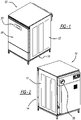
FIG. 1 is a perspective view of a combination washer/dryer machine in accordance with the disclosure. -
FIG. 2 is a perspective rear view of the combination washer/dryer machine ofFIG. 1 . -
FIG. 3 is an elevation side view of the combination washer/dryer machine ofFIG. 1 with a panel removed. -
FIG. 4 is a top plan view of the washer/dryer machine ofFIG. 1 with the panel removed. -
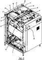
FIG. 5 is a perspective view likeFIG. 2 with panels removed. -
FIG. 6 is a cross-section view ofFIG. 5 along lines 6-6 thereof. - Example embodiments will now be described more fully with reference to the accompanying drawings.
- Turning to the figures, a combination washer/dryer machine is illustrated and designated with the
reference numeral 10. The washing/drying machine 10 includes a plurality ofpanels 12 that define ahousing 14. The front panel includes adoor 16 and acontrol panel 18. Thepanels 12 form an overall rectangular configuration that houses adrum 20 andtub 22 as well as a washing circuit 23 and drying circuit 25. Aframework 24 defines the infrastructure of thehousing 14 and secures thepanels 12. Theframework 24 includes a plurality ofbeams 26 defining an open rectangular configuration. Additionally,crossbeams 28 span between the rectangular skeleton to enhance the reinforcement and rigidity of theframework 24. - An
airflow system 40 is positioned within a cavity orhousing 14. Anair exit opening 42 is on thetub enclosure 22. Thus, heated air for drying the clothes or textiles within the drum exits through theexit opening 42. Aflexible hose 44 connects theair exit opening 42 with theairflow system 40. - The
airflow system 40 includes alint screen box 50 and acentrifugal fan 52. The airflow system could be a single or multiple parts. Thelint screen box 50 is connected withcentrifugal fan 52 via atransition duct 54. Additionally, thecentrifugal fan 52 includes an outlet connecting to thehousing exhaust tube 56. - The
lint screen box 50 is connected by fasteners with thebeams 26 of theframe 24. This holds thelint screen box 50 in position on theframework 24. Additionally, the lint screen box includes adrawer 58 adjacent thecontrol panel 18 enabling a lint screen to be removed from thelint screen box 50. Thus, thedrawer 58 enables the lint screen to be removed from thelint screen box 50 through the front of the combination washing/dryingmachine housing 14. - The
lint screen box 50 includes aninlet 60 that couples with theflexible hose 44. Thus, air exiting thetub 22 is directed into thelint screen box 50. Thelint screen box 50 in the lint box removes or catches lint exiting thetub 22 during the clothes drying cycle. The air in thelint screen box 50 is passed through the intermediate ortransition duct 54 via thefan 52. Thecentrifugal fan 52 draws a vacuum from the tub to withdraw the air from thetub 22. Thecentrifugal fan 52 has anoutlet 64 coupled with theexit tube 56. Thus, air is drawn from the drum/tub through thelint screen box 50 and exits theexhaust tube 56. Theexhaust tube 56 is then coupled with the interior piping of the residence to exhaust the exhaust air to ambient. - A mounting
assembly 70 stationarily secures theairflow system 40 with theframework 24. A plurality offasteners 72 are attached to thelint screen box 50 to secure thelint screen box 50 with theframe structure 24. Also, thelint screen box 50 includes aflange 74 that is positioned inside of an opening in thebeam 26. Thus, this additionally holds thelint screen box 50 in a stationary position inside the housing. - A plurality of
fasteners 76 extend from thecross beam 28 to secure thetransition duct 54 in a stationary position inside thehousing 14. The fasteners may include a bolt and a nut secured on thetransition duct 54 molded into it. Additionally, a bolt could extend from thetransition duct 54 and a nut could be positioned on the bolt once the bolt passes through thecross beam 28. Thetransition duct 54 is coupled with thecentrifugal fan 52. Thetransition duct 54 connect with the inlet of thefan 52 and is secured with the fan at the inlet opening. This enhances the retention of thefan 52 with thecrossbeam 28. The outlet of thefan 52 is coupled with theexhaust tube 56 likewise enhancing the retention of thefan 52 within the housing. Additionally, fasteners may pass through thebeam 26 to secure with thefan 52 to hold it in position with theexhaust tube 56. - Thus, the
airflow system 40 is stationarily positioned within thehousing 14. The fasteners and mountingassembly 70 secure theairflow system 40 with the framework and beams 26, 28. Thus, theairflow system 40 is prevented from moving during operation of the combination washing/dryingmachine 10 during the drying cycle. This eliminates vibration and noise that is created in prior machines during operation. Additionally, by eliminating the movement of the airflow system, this reduces the wear of the system within the housing to prohibit voids that create leakage within the housing. - The foregoing description of the embodiments has been provided for purposes of illustration and description. It is not intended to be exhaustive or to limit the disclosure. Individual elements or features of a particular embodiment are generally not limited to that particular embodiment, but, where applicable, are interchangeable and can be used in a selected embodiment, even if not specifically shown or described. The same may also be varied in many ways. Such variations are not to be regarded as a departure from the disclosure, and all such modifications are intended to be included within the scope of the disclosure.
Claims (12)
- A combination washer/dryer (10) comprising:an airflow exhaust system (40) comprising:- a lint screen box (50) for coupling with an exhaust duct of a tub (22); and- a fan (52) coupled with the lint screen box (50), the fan (52) including an outlet for coupling with an exhaust tube (56);a mounting assembly (70) for stationarily fastening the airflow exhaust system with a housing of the combination washer/dryer (10).
- The combination washer/dryer (10) according to Claim 1, wherein:a transition duct (54) is associated with the lint screen box (50); andthe fan is associated with the transition duct (54).
- The combination washer/dryer (10) of claim 2 including:a housing (14) defining a cavity for receiving washer/dryer components including a drum (20) and a tub (22) positioned inside the housing (14);a door (16) coupled with the housing (14) enabling access to the drum (20); anda flexible hose (44) coupling with an air exit opening (42) from the tub (22);the lint screen box (50) associated with the flexible hose (44).
- The combination washer/dryer as set forth in one of the preceding claims, wherein a frame (24) structure is positioned in the housing (14).
- The combination washer/dryer machine as set forth in one of the preceding claims, wherein the housing (14) includes a plurality of panels (12) secured to the frame structure (24).
- The combination washer/dryer machine as set forth in one of the preceding claims, wherein the door (16) is positioned on one of the panels (12).
- The combination washer/dryer machine as set forth in one of the preceding claims, wherein the door (16) defines a front of the combination washer/dryer machine (10).
- The combination washer/dryer machine as set forth in one of the preceding claims, wherein the exhaust tube (56) extends from one of the panels (12) away from the door (16).
- The combination washer/dryer as set forth in one of the preceding claims, wherein the mounting assembly (70) further comprises fasteners (72) coupled with the airflow exhaust for coupling the airflow exhaust system (40) with a frame (24) coupled with a housing (14).
- The combination washer/dryer as set forth in one of the preceding claims, wherein the lint screen box (50) is secured to the frame (24) via the fasteners (72) adjacent a front panel of the combination washer/dryer.
- The combination washer/dryer as set forth in one of the preceding claims, wherein the intermediate duct (54) is secured to the frame (24) via the fasteners (72).
- The combination washer/dryer as set forth in one of the preceding claims, wherein the fan (52) is secured in position by the association with the intermediate duct (54) and the exhaust tube (56).
Applications Claiming Priority (1)
| Application Number | Priority Date | Filing Date | Title |
|---|---|---|---|
| US17/094,360 US11807973B2 (en) | 2020-11-10 | 2020-11-10 | Combination washer/dryer with a lint screen |
Publications (1)
| Publication Number | Publication Date |
|---|---|
| EP3995614A1 true EP3995614A1 (en) | 2022-05-11 |
Family
ID=81000607
Family Applications (1)
| Application Number | Title | Priority Date | Filing Date |
|---|---|---|---|
| EP21204866.4A Withdrawn EP3995614A1 (en) | 2020-11-10 | 2021-10-26 | Combination washer/dryer with a lint screen |
Country Status (3)
| Country | Link |
|---|---|
| US (1) | US11807973B2 (en) |
| EP (1) | EP3995614A1 (en) |
| CN (1) | CN114541114A (en) |
Families Citing this family (2)
| Publication number | Priority date | Publication date | Assignee | Title |
|---|---|---|---|---|
| EP4365346A4 (en) * | 2021-12-16 | 2024-12-04 | Samsung Electronics Co., Ltd. | LAUNDRY TREATMENT APPARATUS AND CONTROL METHOD FOR A LAUNDRY TREATMENT APPARATUS |
| US12331451B2 (en) * | 2022-02-21 | 2025-06-17 | Haier Us Appliance Solutions, Inc. | Dryer appliance and compartment for non-tumbling items |
Citations (4)
| Publication number | Priority date | Publication date | Assignee | Title |
|---|---|---|---|---|
| US20040221474A1 (en) * | 2003-05-05 | 2004-11-11 | Dennis Slutsky | Combination washer/dryer having common heat source |
| US20060075577A1 (en) * | 2004-10-08 | 2006-04-13 | Lg Electronics Inc. | Washing machine and method of controlling the same |
| EP1669487A1 (en) * | 2004-12-10 | 2006-06-14 | LG Electronics, Inc. | Washing machine combined with dryer |
| EP2843100A1 (en) * | 2013-08-30 | 2015-03-04 | Electrolux Appliances Aktiebolag | Laundry appliance having a water filter |
Family Cites Families (17)
| Publication number | Priority date | Publication date | Assignee | Title |
|---|---|---|---|---|
| GB1461073A (en) | 1973-06-01 | 1977-01-13 | Colston Appliances Ltd | Washing machine having a hot air dryer |
| ES242354Y (en) | 1979-03-16 | 1979-11-16 | DRYING DEVICE FOR CLOTHES WASHING MACHINES. | |
| KR20060031164A (en) | 2004-10-07 | 2006-04-12 | 엘지전자 주식회사 | Dry washing machine |
| EP1650338A3 (en) | 2004-10-22 | 2006-07-05 | LG Electronics, Inc. | Washing machine combined with dryer |
| KR20060040352A (en) | 2004-11-05 | 2006-05-10 | 엘지전자 주식회사 | Dry washing machine with lint filter assembly |
| KR100700780B1 (en) | 2004-11-12 | 2007-03-27 | 엘지전자 주식회사 | How to control washing in a dry washing machine and a dry washing machine |
| KR100738714B1 (en) | 2004-12-10 | 2007-07-12 | 엘지전자 주식회사 | Drying Washer |
| US7501005B2 (en) * | 2005-02-28 | 2009-03-10 | Caterpillar Inc. | Exhaust treatment device having submerged connecting flanges |
| JP4236678B2 (en) | 2006-10-26 | 2009-03-11 | 株式会社東芝 | Washing and drying machine |
| JP2009125453A (en) * | 2007-11-27 | 2009-06-11 | Toshiba Corp | Washing and drying machine |
| WO2010114332A2 (en) * | 2009-04-02 | 2010-10-07 | (주)엘지전자 | Clothes dryer having a steam generator using a hot air heater |
| KR20120066549A (en) * | 2010-12-14 | 2012-06-22 | 삼성전자주식회사 | Clothing dryer |
| US20120304396A1 (en) * | 2011-06-02 | 2012-12-06 | General Electric Company | Overnight cycle for horizontal axis clothes washer |
| KR102086508B1 (en) * | 2013-07-16 | 2020-03-09 | 엘지전자 주식회사 | Laundry drying Apparatus |
| KR20150081602A (en) | 2014-01-06 | 2015-07-15 | 삼성전자주식회사 | Washing machine with drying apparatus and method to control thereof |
| EP3775356B1 (en) | 2018-04-02 | 2023-01-25 | Arçelik Anonim Sirketi | A laundry washer-dryer |
| US11434601B2 (en) * | 2019-12-20 | 2022-09-06 | Whirlpool Corporation | Laundry treating appliance having a condenser |
-
2020
- 2020-11-10 US US17/094,360 patent/US11807973B2/en active Active
-
2021
- 2021-10-26 EP EP21204866.4A patent/EP3995614A1/en not_active Withdrawn
- 2021-11-10 CN CN202111324763.8A patent/CN114541114A/en active Pending
Patent Citations (4)
| Publication number | Priority date | Publication date | Assignee | Title |
|---|---|---|---|---|
| US20040221474A1 (en) * | 2003-05-05 | 2004-11-11 | Dennis Slutsky | Combination washer/dryer having common heat source |
| US20060075577A1 (en) * | 2004-10-08 | 2006-04-13 | Lg Electronics Inc. | Washing machine and method of controlling the same |
| EP1669487A1 (en) * | 2004-12-10 | 2006-06-14 | LG Electronics, Inc. | Washing machine combined with dryer |
| EP2843100A1 (en) * | 2013-08-30 | 2015-03-04 | Electrolux Appliances Aktiebolag | Laundry appliance having a water filter |
Also Published As
| Publication number | Publication date |
|---|---|
| US20220145508A1 (en) | 2022-05-12 |
| CN114541114A (en) | 2022-05-27 |
| US11807973B2 (en) | 2023-11-07 |
Similar Documents
| Publication | Publication Date | Title |
|---|---|---|
| US11807973B2 (en) | Combination washer/dryer with a lint screen | |
| US12031255B2 (en) | Front load all-in-one washer/dryer combo reverse airflow system | |
| EP3124676B1 (en) | Method to position a rack in a laundry dryer and laundry dryer including a rack | |
| US20080265721A1 (en) | Laundry treating apparatus | |
| US9297109B2 (en) | Laundry dryer | |
| CN102301052A (en) | Heat pump module and laundry treatment device using the same | |
| EP2935683B1 (en) | Laundry treating appliance | |
| US4989347A (en) | Dryer transition duct | |
| KR20160097890A (en) | Clothing dryer | |
| KR20140100227A (en) | Laundry Machine | |
| WO2021010601A1 (en) | Clothing care apparatus | |
| US5066050A (en) | Dryer transition duct | |
| KR20050062869A (en) | Structure of back cover in clothes dryer | |
| EP3265600B1 (en) | Laundry treatment apparatus | |
| JP5449921B2 (en) | Drum washing machine | |
| KR20210056306A (en) | Fabric treating apparatus | |
| CN214529776U (en) | Combined clothes treating device | |
| CN106978698A (en) | washing and drying integrated washing machine | |
| EP3124688A1 (en) | A laundry dryer | |
| CN114045629A (en) | Drum washing machine with drying function | |
| US10851489B2 (en) | Laundry treatment apparatus | |
| EP3995613A1 (en) | Washer/dryer | |
| CN115012161B (en) | Combined clothes processing device | |
| JP2011143310A (en) | Drum washing machine | |
| US20250027259A1 (en) | Clothes treatment apparatus, and method for assembling clothes treatment apparatus |
Legal Events
| Date | Code | Title | Description |
|---|---|---|---|
| PUAI | Public reference made under article 153(3) epc to a published international application that has entered the european phase |
Free format text: ORIGINAL CODE: 0009012 |
|
| STAA | Information on the status of an ep patent application or granted ep patent |
Free format text: STATUS: THE APPLICATION HAS BEEN PUBLISHED |
|
| AK | Designated contracting states |
Kind code of ref document: A1 Designated state(s): AL AT BE BG CH CY CZ DE DK EE ES FI FR GB GR HR HU IE IS IT LI LT LU LV MC MK MT NL NO PL PT RO RS SE SI SK SM TR |
|
| STAA | Information on the status of an ep patent application or granted ep patent |
Free format text: STATUS: THE APPLICATION IS DEEMED TO BE WITHDRAWN |
|
| 18D | Application deemed to be withdrawn |
Effective date: 20221112 |