EP3995601A1 - Bilayer thermal barrier coatings with an advanced interface - Google Patents
Bilayer thermal barrier coatings with an advanced interface Download PDFInfo
- Publication number
- EP3995601A1 EP3995601A1 EP20205571.1A EP20205571A EP3995601A1 EP 3995601 A1 EP3995601 A1 EP 3995601A1 EP 20205571 A EP20205571 A EP 20205571A EP 3995601 A1 EP3995601 A1 EP 3995601A1
- Authority
- EP
- European Patent Office
- Prior art keywords
- coating
- ceramic
- particles
- last pass
- segmented
- Prior art date
- Legal status (The legal status is an assumption and is not a legal conclusion. Google has not performed a legal analysis and makes no representation as to the accuracy of the status listed.)
- Withdrawn
Links
- 239000012720 thermal barrier coating Substances 0.000 title description 5
- 238000000576 coating method Methods 0.000 claims abstract description 65
- 239000011248 coating agent Substances 0.000 claims abstract description 60
- 238000005524 ceramic coating Methods 0.000 claims abstract description 24
- 239000000843 powder Substances 0.000 claims abstract description 12
- 238000005507 spraying Methods 0.000 claims abstract description 8
- 239000000919 ceramic Substances 0.000 claims description 20
- 239000002245 particle Substances 0.000 claims description 10
- 238000002844 melting Methods 0.000 claims description 6
- 230000008018 melting Effects 0.000 claims description 6
- 229910002078 fully stabilized zirconia Inorganic materials 0.000 claims description 5
- 238000000034 method Methods 0.000 claims description 5
- 229910002077 partially stabilized zirconia Inorganic materials 0.000 claims description 4
- 239000000758 substrate Substances 0.000 claims description 4
- 235000012771 pancakes Nutrition 0.000 claims description 3
- 229910017052 cobalt Inorganic materials 0.000 claims description 2
- 239000010941 cobalt Substances 0.000 claims description 2
- GUTLYIVDDKVIGB-UHFFFAOYSA-N cobalt atom Chemical compound [Co] GUTLYIVDDKVIGB-UHFFFAOYSA-N 0.000 claims description 2
- 239000010419 fine particle Substances 0.000 claims description 2
- 229910000601 superalloy Inorganic materials 0.000 claims description 2
- 238000000151 deposition Methods 0.000 claims 1
- 239000000203 mixture Substances 0.000 claims 1
- 230000003628 erosive effect Effects 0.000 description 4
- PXHVJJICTQNCMI-UHFFFAOYSA-N Nickel Chemical compound [Ni] PXHVJJICTQNCMI-UHFFFAOYSA-N 0.000 description 2
- 230000002411 adverse Effects 0.000 description 2
- 238000013459 approach Methods 0.000 description 2
- 230000036961 partial effect Effects 0.000 description 2
- 229910002076 stabilized zirconia Inorganic materials 0.000 description 2
- 230000003247 decreasing effect Effects 0.000 description 1
- 230000032798 delamination Effects 0.000 description 1
- 230000001419 dependent effect Effects 0.000 description 1
- 229910052759 nickel Inorganic materials 0.000 description 1
- 230000002829 reductive effect Effects 0.000 description 1
- 238000009877 rendering Methods 0.000 description 1
- 230000035945 sensitivity Effects 0.000 description 1
- 238000005245 sintering Methods 0.000 description 1
- 239000007921 spray Substances 0.000 description 1
- 230000003746 surface roughness Effects 0.000 description 1
- 238000009736 wetting Methods 0.000 description 1
Images
Classifications
-
- C—CHEMISTRY; METALLURGY
- C23—COATING METALLIC MATERIAL; COATING MATERIAL WITH METALLIC MATERIAL; CHEMICAL SURFACE TREATMENT; DIFFUSION TREATMENT OF METALLIC MATERIAL; COATING BY VACUUM EVAPORATION, BY SPUTTERING, BY ION IMPLANTATION OR BY CHEMICAL VAPOUR DEPOSITION, IN GENERAL; INHIBITING CORROSION OF METALLIC MATERIAL OR INCRUSTATION IN GENERAL
- C23C—COATING METALLIC MATERIAL; COATING MATERIAL WITH METALLIC MATERIAL; SURFACE TREATMENT OF METALLIC MATERIAL BY DIFFUSION INTO THE SURFACE, BY CHEMICAL CONVERSION OR SUBSTITUTION; COATING BY VACUUM EVAPORATION, BY SPUTTERING, BY ION IMPLANTATION OR BY CHEMICAL VAPOUR DEPOSITION, IN GENERAL
- C23C4/00—Coating by spraying the coating material in the molten state, e.g. by flame, plasma or electric discharge
- C23C4/02—Pretreatment of the material to be coated, e.g. for coating on selected surface areas
-
- C—CHEMISTRY; METALLURGY
- C23—COATING METALLIC MATERIAL; COATING MATERIAL WITH METALLIC MATERIAL; CHEMICAL SURFACE TREATMENT; DIFFUSION TREATMENT OF METALLIC MATERIAL; COATING BY VACUUM EVAPORATION, BY SPUTTERING, BY ION IMPLANTATION OR BY CHEMICAL VAPOUR DEPOSITION, IN GENERAL; INHIBITING CORROSION OF METALLIC MATERIAL OR INCRUSTATION IN GENERAL
- C23C—COATING METALLIC MATERIAL; COATING MATERIAL WITH METALLIC MATERIAL; SURFACE TREATMENT OF METALLIC MATERIAL BY DIFFUSION INTO THE SURFACE, BY CHEMICAL CONVERSION OR SUBSTITUTION; COATING BY VACUUM EVAPORATION, BY SPUTTERING, BY ION IMPLANTATION OR BY CHEMICAL VAPOUR DEPOSITION, IN GENERAL
- C23C4/00—Coating by spraying the coating material in the molten state, e.g. by flame, plasma or electric discharge
- C23C4/04—Coating by spraying the coating material in the molten state, e.g. by flame, plasma or electric discharge characterised by the coating material
- C23C4/10—Oxides, borides, carbides, nitrides or silicides; Mixtures thereof
-
- C—CHEMISTRY; METALLURGY
- C22—METALLURGY; FERROUS OR NON-FERROUS ALLOYS; TREATMENT OF ALLOYS OR NON-FERROUS METALS
- C22C—ALLOYS
- C22C19/00—Alloys based on nickel or cobalt
-
- C—CHEMISTRY; METALLURGY
- C23—COATING METALLIC MATERIAL; COATING MATERIAL WITH METALLIC MATERIAL; CHEMICAL SURFACE TREATMENT; DIFFUSION TREATMENT OF METALLIC MATERIAL; COATING BY VACUUM EVAPORATION, BY SPUTTERING, BY ION IMPLANTATION OR BY CHEMICAL VAPOUR DEPOSITION, IN GENERAL; INHIBITING CORROSION OF METALLIC MATERIAL OR INCRUSTATION IN GENERAL
- C23C—COATING METALLIC MATERIAL; COATING MATERIAL WITH METALLIC MATERIAL; SURFACE TREATMENT OF METALLIC MATERIAL BY DIFFUSION INTO THE SURFACE, BY CHEMICAL CONVERSION OR SUBSTITUTION; COATING BY VACUUM EVAPORATION, BY SPUTTERING, BY ION IMPLANTATION OR BY CHEMICAL VAPOUR DEPOSITION, IN GENERAL
- C23C24/00—Coating starting from inorganic powder
- C23C24/02—Coating starting from inorganic powder by application of pressure only
- C23C24/04—Impact or kinetic deposition of particles
-
- C—CHEMISTRY; METALLURGY
- C23—COATING METALLIC MATERIAL; COATING MATERIAL WITH METALLIC MATERIAL; CHEMICAL SURFACE TREATMENT; DIFFUSION TREATMENT OF METALLIC MATERIAL; COATING BY VACUUM EVAPORATION, BY SPUTTERING, BY ION IMPLANTATION OR BY CHEMICAL VAPOUR DEPOSITION, IN GENERAL; INHIBITING CORROSION OF METALLIC MATERIAL OR INCRUSTATION IN GENERAL
- C23C—COATING METALLIC MATERIAL; COATING MATERIAL WITH METALLIC MATERIAL; SURFACE TREATMENT OF METALLIC MATERIAL BY DIFFUSION INTO THE SURFACE, BY CHEMICAL CONVERSION OR SUBSTITUTION; COATING BY VACUUM EVAPORATION, BY SPUTTERING, BY ION IMPLANTATION OR BY CHEMICAL VAPOUR DEPOSITION, IN GENERAL
- C23C28/00—Coating for obtaining at least two superposed coatings either by methods not provided for in a single one of groups C23C2/00 - C23C26/00 or by combinations of methods provided for in subclasses C23C and C25C or C25D
- C23C28/04—Coating for obtaining at least two superposed coatings either by methods not provided for in a single one of groups C23C2/00 - C23C26/00 or by combinations of methods provided for in subclasses C23C and C25C or C25D only coatings of inorganic non-metallic material
- C23C28/042—Coating for obtaining at least two superposed coatings either by methods not provided for in a single one of groups C23C2/00 - C23C26/00 or by combinations of methods provided for in subclasses C23C and C25C or C25D only coatings of inorganic non-metallic material including a refractory ceramic layer, e.g. refractory metal oxides, ZrO2, rare earth oxides
-
- C—CHEMISTRY; METALLURGY
- C23—COATING METALLIC MATERIAL; COATING MATERIAL WITH METALLIC MATERIAL; CHEMICAL SURFACE TREATMENT; DIFFUSION TREATMENT OF METALLIC MATERIAL; COATING BY VACUUM EVAPORATION, BY SPUTTERING, BY ION IMPLANTATION OR BY CHEMICAL VAPOUR DEPOSITION, IN GENERAL; INHIBITING CORROSION OF METALLIC MATERIAL OR INCRUSTATION IN GENERAL
- C23C—COATING METALLIC MATERIAL; COATING MATERIAL WITH METALLIC MATERIAL; SURFACE TREATMENT OF METALLIC MATERIAL BY DIFFUSION INTO THE SURFACE, BY CHEMICAL CONVERSION OR SUBSTITUTION; COATING BY VACUUM EVAPORATION, BY SPUTTERING, BY ION IMPLANTATION OR BY CHEMICAL VAPOUR DEPOSITION, IN GENERAL
- C23C28/00—Coating for obtaining at least two superposed coatings either by methods not provided for in a single one of groups C23C2/00 - C23C26/00 or by combinations of methods provided for in subclasses C23C and C25C or C25D
- C23C28/04—Coating for obtaining at least two superposed coatings either by methods not provided for in a single one of groups C23C2/00 - C23C26/00 or by combinations of methods provided for in subclasses C23C and C25C or C25D only coatings of inorganic non-metallic material
- C23C28/048—Coating for obtaining at least two superposed coatings either by methods not provided for in a single one of groups C23C2/00 - C23C26/00 or by combinations of methods provided for in subclasses C23C and C25C or C25D only coatings of inorganic non-metallic material with layers graded in composition or physical properties
-
- C—CHEMISTRY; METALLURGY
- C23—COATING METALLIC MATERIAL; COATING MATERIAL WITH METALLIC MATERIAL; CHEMICAL SURFACE TREATMENT; DIFFUSION TREATMENT OF METALLIC MATERIAL; COATING BY VACUUM EVAPORATION, BY SPUTTERING, BY ION IMPLANTATION OR BY CHEMICAL VAPOUR DEPOSITION, IN GENERAL; INHIBITING CORROSION OF METALLIC MATERIAL OR INCRUSTATION IN GENERAL
- C23C—COATING METALLIC MATERIAL; COATING MATERIAL WITH METALLIC MATERIAL; SURFACE TREATMENT OF METALLIC MATERIAL BY DIFFUSION INTO THE SURFACE, BY CHEMICAL CONVERSION OR SUBSTITUTION; COATING BY VACUUM EVAPORATION, BY SPUTTERING, BY ION IMPLANTATION OR BY CHEMICAL VAPOUR DEPOSITION, IN GENERAL
- C23C4/00—Coating by spraying the coating material in the molten state, e.g. by flame, plasma or electric discharge
- C23C4/04—Coating by spraying the coating material in the molten state, e.g. by flame, plasma or electric discharge characterised by the coating material
- C23C4/10—Oxides, borides, carbides, nitrides or silicides; Mixtures thereof
- C23C4/11—Oxides
-
- C—CHEMISTRY; METALLURGY
- C23—COATING METALLIC MATERIAL; COATING MATERIAL WITH METALLIC MATERIAL; CHEMICAL SURFACE TREATMENT; DIFFUSION TREATMENT OF METALLIC MATERIAL; COATING BY VACUUM EVAPORATION, BY SPUTTERING, BY ION IMPLANTATION OR BY CHEMICAL VAPOUR DEPOSITION, IN GENERAL; INHIBITING CORROSION OF METALLIC MATERIAL OR INCRUSTATION IN GENERAL
- C23C—COATING METALLIC MATERIAL; COATING MATERIAL WITH METALLIC MATERIAL; SURFACE TREATMENT OF METALLIC MATERIAL BY DIFFUSION INTO THE SURFACE, BY CHEMICAL CONVERSION OR SUBSTITUTION; COATING BY VACUUM EVAPORATION, BY SPUTTERING, BY ION IMPLANTATION OR BY CHEMICAL VAPOUR DEPOSITION, IN GENERAL
- C23C4/00—Coating by spraying the coating material in the molten state, e.g. by flame, plasma or electric discharge
- C23C4/12—Coating by spraying the coating material in the molten state, e.g. by flame, plasma or electric discharge characterised by the method of spraying
- C23C4/123—Spraying molten metal
-
- C—CHEMISTRY; METALLURGY
- C23—COATING METALLIC MATERIAL; COATING MATERIAL WITH METALLIC MATERIAL; CHEMICAL SURFACE TREATMENT; DIFFUSION TREATMENT OF METALLIC MATERIAL; COATING BY VACUUM EVAPORATION, BY SPUTTERING, BY ION IMPLANTATION OR BY CHEMICAL VAPOUR DEPOSITION, IN GENERAL; INHIBITING CORROSION OF METALLIC MATERIAL OR INCRUSTATION IN GENERAL
- C23C—COATING METALLIC MATERIAL; COATING MATERIAL WITH METALLIC MATERIAL; SURFACE TREATMENT OF METALLIC MATERIAL BY DIFFUSION INTO THE SURFACE, BY CHEMICAL CONVERSION OR SUBSTITUTION; COATING BY VACUUM EVAPORATION, BY SPUTTERING, BY ION IMPLANTATION OR BY CHEMICAL VAPOUR DEPOSITION, IN GENERAL
- C23C4/00—Coating by spraying the coating material in the molten state, e.g. by flame, plasma or electric discharge
- C23C4/12—Coating by spraying the coating material in the molten state, e.g. by flame, plasma or electric discharge characterised by the method of spraying
- C23C4/134—Plasma spraying
-
- F—MECHANICAL ENGINEERING; LIGHTING; HEATING; WEAPONS; BLASTING
- F01—MACHINES OR ENGINES IN GENERAL; ENGINE PLANTS IN GENERAL; STEAM ENGINES
- F01D—NON-POSITIVE DISPLACEMENT MACHINES OR ENGINES, e.g. STEAM TURBINES
- F01D5/00—Blades; Blade-carrying members; Heating, heat-insulating, cooling or antivibration means on the blades or the members
- F01D5/12—Blades
- F01D5/28—Selecting particular materials; Particular measures relating thereto; Measures against erosion or corrosion
- F01D5/288—Protective coatings for blades
-
- F—MECHANICAL ENGINEERING; LIGHTING; HEATING; WEAPONS; BLASTING
- F05—INDEXING SCHEMES RELATING TO ENGINES OR PUMPS IN VARIOUS SUBCLASSES OF CLASSES F01-F04
- F05D—INDEXING SCHEME FOR ASPECTS RELATING TO NON-POSITIVE-DISPLACEMENT MACHINES OR ENGINES, GAS-TURBINES OR JET-PROPULSION PLANTS
- F05D2300/00—Materials; Properties thereof
- F05D2300/20—Oxide or non-oxide ceramics
- F05D2300/21—Oxide ceramics
- F05D2300/2118—Zirconium oxides
-
- F—MECHANICAL ENGINEERING; LIGHTING; HEATING; WEAPONS; BLASTING
- F05—INDEXING SCHEMES RELATING TO ENGINES OR PUMPS IN VARIOUS SUBCLASSES OF CLASSES F01-F04
- F05D—INDEXING SCHEME FOR ASPECTS RELATING TO NON-POSITIVE-DISPLACEMENT MACHINES OR ENGINES, GAS-TURBINES OR JET-PROPULSION PLANTS
- F05D2300/00—Materials; Properties thereof
- F05D2300/50—Intrinsic material properties or characteristics
- F05D2300/516—Surface roughness
Definitions
- the invention relates to a component with a ceramic coating system which reveals a two layered ceramic coating system.
- TBC Turbine Inlet Temperatures
- TBC Advanced Thermal Barrier Coatings
- TBC typically comprise a partially high fracture toughness partially stabilized zirconia lower coating and one or multiple lower fracture ceramic upper coating.
- a very typical ceramic coating is a fully stabilized zirconia thermal barrier coating, which typically shows low fracture toughness, sintering resistance and phase stability at high temperatures.
- fully stabilized coatings are characterized by low fracture toughness and thus low erosion resistance and are deposited on top of partially stabilized zirconia coatings, bonded by a ceramic-ceramic interface, that can be rather weak and can lead to complete delamination of the upper coating, with adverse consequences regarding the thermal protection of the underlying component.
- the solution was to deposit both ceramic coatings, the lower coating partially stabilized and the upper coating fully stabilized, especially with a segmented microstructure.
- a segmented microstructure is characterized by low porosity ( ⁇ 3%) and vertical cracks that travel along the coatings thickness, rendering it thermal compliant, which means the ceramic coating shows increased ability to absorb and withstand thermal strain. Typically, the vertical cracks will extend and continue from the lower coating to the upper coating.
- the dense segmented microstructure can increase the erosion resistance of the ceramic coatings at least three times.
- a segmented lower coating is in general rather smooth and the asperities or cavities that can assist with the mechanical interlocking are small or few. This can affect the robustness and the strength of the bond between the two ceramic coatings.
- Concerning temperature ideally a strong interface will appear when the upper stabilized coating will be deposited on an intensely preheated lower coating. High temperature will help with the wetting and spreading of the incoming fully stabilized particles on the partially stabilized lower coating. The particles will spread evenly and fill almost all cavities and asperities improving in this manner the mechanical interlocking between the two coatings.
- homogeneous preheating for bulky components with complex geometries and varying metallic wall thickness can be challenging.
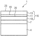
- the figure shows an inventive ceramic coating system of a component.
- a coating is usually applied by a spray torch passing over the same surface several times by applying powder in layers.
- the current invention improves the strength and robustness of the interface interlocking and bonding between two ceramic coatings. The manner it does that, is through achieving higher roughness on a ceramic lower coating, without sacrificing its microstructure.
- the ceramic lower coating 10 is sprayed by using a finer particle powder, especially using a powder cut, in order to achieve maximum melting degree, which in turn reduces the porosity and promotes the vertical crack appearance.
- the reason for the smooth surface of the coating is the almost complete melting of the powder particles that resemble pancakes when they are deposited.
- the resulting ceramic coating system 16 will comprise of the following:
- the present invention comes to improve the robustness of a bilayer ceramic coating system 16, which is especially segmented.
- Experience has shown the importance of temperature control during the spraying of bilayer ceramic coating systems 16 and temperature control can be rather challenging during the spraying of large components.
- the sensitivity of the ceramic coating system 16 to temperature is decreased providing an overall robuster ceramic coating system.
- the adoption of both approaches described above is rather easy and both can be easily incorporated in the spraying sequence of the components.
- the figure shows an inventive component 1.
- the component 1 has especially a metallic substrate 4, which is preferably a nickel or cobalt based superalloy.
- NiCoCrAlY On the metallic substrate 4 there is a metallic bond coat 7, especially on a NiCoCrAl base, means NiCoCrAlY, NiCoCrAlYSi, NiCoCrAlYRe, NiCoCrAlYTa, ....
Abstract
The bonding capacity of a ceramic coating system (16) is improved by adapting the coating parameters such as size of the powder and changing of the parameters of the spraying system.
Description
- The invention relates to a component with a ceramic coating system which reveals a two layered ceramic coating system.
- The ever increasing Turbine Inlet Temperatures (TIT) have led to the introduction of advanced Thermal Barrier Coatings (TBC), that typically appear as multilayer ceramic systems. These TBC typically comprise a partially high fracture toughness partially stabilized zirconia lower coating and one or multiple lower fracture ceramic upper coating.
A very typical ceramic coating is a fully stabilized zirconia thermal barrier coating, which typically shows low fracture toughness, sintering resistance and phase stability at high temperatures.
However, fully stabilized coatings are characterized by low fracture toughness and thus low erosion resistance and are deposited on top of partially stabilized zirconia coatings, bonded by a ceramic-ceramic interface, that can be rather weak and can lead to complete delamination of the upper coating, with adverse consequences regarding the thermal protection of the underlying component. - However, the introduction of the multilayer thermal protection ceramic coatings comes with two caveats:
- i) The associated low fracture toughness of the fully stabilized ceramic upper coating, which impacts adversely its erosion resistance,
- ii) An inherited weak interface between ceramic lower coating and ceramic upper coating.
- Regarding the erosion resistance of the ceramic coating system, the solution was to deposit both ceramic coatings, the lower coating partially stabilized and the upper coating fully stabilized, especially with a segmented microstructure.
- A segmented microstructure is characterized by low porosity (<3%) and vertical cracks that travel along the coatings thickness, rendering it thermal compliant, which means the ceramic coating shows increased ability to absorb and withstand thermal strain. Typically, the vertical cracks will extend and continue from the lower coating to the upper coating. The dense segmented microstructure can increase the erosion resistance of the ceramic coatings at least three times.
- Regarding the bonding capability of the two segmented ceramic coatings, the most important elements that influence that are surface roughness and temperature control.
Regarding roughness, a segmented lower coating is in general rather smooth and the asperities or cavities that can assist with the mechanical interlocking are small or few. This can affect the robustness and the strength of the bond between the two ceramic coatings.
Concerning temperature, ideally a strong interface will appear when the upper stabilized coating will be deposited on an intensely preheated lower coating. High temperature will help with the wetting and spreading of the incoming fully stabilized particles on the partially stabilized lower coating. The particles will spread evenly and fill almost all cavities and asperities improving in this manner the mechanical interlocking between the two coatings.
However, homogeneous preheating for bulky components with complex geometries and varying metallic wall thickness can be challenging. - Is therefore aim of the invention to improve the problem listed above.
- The problem is solved by a component according to claim 1. In the dependent claims further advantages are listed which can be arbitrarily combined with each other to yield further advantages.
- The figure shows an inventive ceramic coating system of a component.
- A coating is usually applied by a spray torch passing over the same surface several times by applying powder in layers.
- The current invention improves the strength and robustness of the interface interlocking and bonding between two ceramic coatings. The manner it does that, is through achieving higher roughness on a ceramic lower coating, without sacrificing its microstructure.
- That can be achieved as following:
Typically, the ceramiclower coating 10 is sprayed by using a finer particle powder, especially using a powder cut, in order to achieve maximum melting degree, which in turn reduces the porosity and promotes the vertical crack appearance. The reason for the smooth surface of the coating is the almost complete melting of the powder particles that resemble pancakes when they are deposited. - Usage of coarser with grain sizes particles, especially >45um will reduce their melting degree, possibly increase the inherent porosity in the coating and thus reduce the population of vertical cracks per unit of length and ultimately the thermal compliance of the coating.
- The solution to that, is to adopt a "flash" coating approach. That means to deposit a rough thin coating intermediated between the lower coating and the upper coating. That can be achieved with two methods:
- 1. Change of the spraying parameters of the
lower coating 10 during the last pass(es):
By adopting colder parameters during the last pass(es) the melting degree of the fine particles is significantly reduced and the particles are deposited semimolten and not as flatten pancakes. That will increase significantly the roughness without affecting the microstructure of the lower coating. - 2. Change of the powder for the last pass(es) of the ceramic
lower coating 10. The powder can be changed and replaced by coarser particles (especially >45um) in order to deposit the last pass(es) of the ceramic lower coating. - Essentially, the resulting
ceramic coating system 16 will comprise of the following: - a) partial stabilized Zirconia (PSZ) as ceramic
lower coating 10 sprayed with fine powder on a substrate 4 or metallic bond coat 7 having asurface 20, - b) a thin coating of partial stabilized Zirconia sprayed in the middle (ceramic intermediate coating 11) with a
rougher surface 19, - c) fully stabilized Zirconia (FSZ) as ceramic
upper coating 13 sprayed with fine powder; theupper coating 13 represents theouter surface 23. - The present invention comes to improve the robustness of a bilayer
ceramic coating system 16, which is especially segmented.
Experience has shown the importance of temperature control during the spraying of bilayerceramic coating systems 16 and temperature control can be rather challenging during the spraying of large components. With the introduction of arough surface 19 between the two especially segmentedcoatings ceramic coating system 16 to temperature is decreased providing an overall robuster ceramic coating system. The adoption of both approaches described above is rather easy and both can be easily incorporated in the spraying sequence of the components. - The figure shows an inventive component 1.
- The component 1 has especially a metallic substrate 4, which is preferably a nickel or cobalt based superalloy.
- On the metallic substrate 4 there is a metallic bond coat 7, especially on a NiCoCrAl base, means NiCoCrAlY, NiCoCrAlYSi, NiCoCrAlYRe, NiCoCrAlYTa, ....
- On top of the metallic bond coat 7 there is the
ceramic coating system 16 as described above: - a PSZ segmented
lower coating 10 - a PSZ segmented
intermediate coating 11 - a FSZ segmented
upper coating 13.
Claims (6)
- Component (1),
comprising at least:a substrate (4),especially a nickel- or cobalt-based superalloy,a metallic bond coat (7),especially based on a NiCoCrAl composition,a ceramic coating system (16)with an lower ceramic coating (10) andan upper ceramic coating (13),characterized by that,wherein an intermediate coating (11) is located between lower coating (10) and upper coating (13),providing a rougher surface (19)which has a maximum thickness of 25% of the thickness of the lower coating (10) or of the upper coating (13). - Coating system according to claim 1,
wherein the lower coating (10) reveals a finer microstructure the upper coating (13). - Method to produce a ceramic coating system according to claim 1,
comprising the steps:spraying the lower ceramic coating (10),especially by using a fine particles powder,in order to achieve maximum melting degree,depositing an intermediate coating (11):eitherby changing of the spraying parameters of the ceramic lower (10) coating during the last pass(es)by adopting colder parameters during the last pass(es) which reduces the melting degree of the particles significantly andthe particles are deposited semimolten and not as flatten pancakes,leading to an increase significantly the roughness,
orchanging the powder for the last pass(es) of the ceramic lower coating (10) by replacing it by coarser particles, especially larger than 45pm,in order to deposit the last pass(es) on the intermediate coating (11) onto the ceramic lower coating (10),and finally spraying a fully stabilized ceramic upper coating (13) sprayed with fine powder. - Coating or method according to any of the claims 1, 2 or 3,
wherein the ceramic lower coating (10) is a partially stabilized Zirconia based coating,
and is especially segmented. - Coating or method according to any of the claims 1, 2, 3 or 4,
wherein the ceramic intermediate coating (11) is a partially stabilized Zirconia based coating,
and is especially segmented. - Coating or method according to any of the claims 1, 2, 3, 4 or 5,
wherein the ceramic upper coating (13) is a fully stabilized Zirconia based coating,
and is especially segmented.
Priority Applications (6)
| Application Number | Priority Date | Filing Date | Title |
|---|---|---|---|
| EP20205571.1A EP3995601A1 (en) | 2020-11-04 | 2020-11-04 | Bilayer thermal barrier coatings with an advanced interface |
| KR1020237018329A KR20230097141A (en) | 2020-11-04 | 2021-10-05 | Double-layer thermal barrier coating with improved interface |
| PCT/EP2021/077439 WO2022096211A1 (en) | 2020-11-04 | 2021-10-05 | Bilayer thermal barrier coatings with an advanced interface |
| CN202180073240.2A CN116615573A (en) | 2020-11-04 | 2021-10-05 | Bilayer thermal barrier coating with advanced interfaces |
| US18/033,099 US20230383393A1 (en) | 2020-11-04 | 2021-10-05 | Bilayer thermal barrier coatings with an advanced interface |
| EP21794312.5A EP4208580A1 (en) | 2020-11-04 | 2021-10-05 | Bilayer thermal barrier coatings with an advanced interface |
Applications Claiming Priority (1)
| Application Number | Priority Date | Filing Date | Title |
|---|---|---|---|
| EP20205571.1A EP3995601A1 (en) | 2020-11-04 | 2020-11-04 | Bilayer thermal barrier coatings with an advanced interface |
Publications (1)
| Publication Number | Publication Date |
|---|---|
| EP3995601A1 true EP3995601A1 (en) | 2022-05-11 |
Family
ID=73059641
Family Applications (2)
| Application Number | Title | Priority Date | Filing Date |
|---|---|---|---|
| EP20205571.1A Withdrawn EP3995601A1 (en) | 2020-11-04 | 2020-11-04 | Bilayer thermal barrier coatings with an advanced interface |
| EP21794312.5A Pending EP4208580A1 (en) | 2020-11-04 | 2021-10-05 | Bilayer thermal barrier coatings with an advanced interface |
Family Applications After (1)
| Application Number | Title | Priority Date | Filing Date |
|---|---|---|---|
| EP21794312.5A Pending EP4208580A1 (en) | 2020-11-04 | 2021-10-05 | Bilayer thermal barrier coatings with an advanced interface |
Country Status (5)
| Country | Link |
|---|---|
| US (1) | US20230383393A1 (en) |
| EP (2) | EP3995601A1 (en) |
| KR (1) | KR20230097141A (en) |
| CN (1) | CN116615573A (en) |
| WO (1) | WO2022096211A1 (en) |
Citations (3)
| Publication number | Priority date | Publication date | Assignee | Title |
|---|---|---|---|---|
| US20050170200A1 (en) * | 2004-02-03 | 2005-08-04 | General Electric Company | Thermal barrier coating system |
| WO2015080804A1 (en) * | 2013-11-26 | 2015-06-04 | Praxair S.T. Technology, Inc. | Modified thermal barrier composite coatings |
| EP3438325A1 (en) * | 2017-07-31 | 2019-02-06 | General Electric Company | Improved adhesion of thermal spray coatings over a smooth surface |
-
2020
- 2020-11-04 EP EP20205571.1A patent/EP3995601A1/en not_active Withdrawn
-
2021
- 2021-10-05 WO PCT/EP2021/077439 patent/WO2022096211A1/en active Application Filing
- 2021-10-05 CN CN202180073240.2A patent/CN116615573A/en active Pending
- 2021-10-05 EP EP21794312.5A patent/EP4208580A1/en active Pending
- 2021-10-05 KR KR1020237018329A patent/KR20230097141A/en unknown
- 2021-10-05 US US18/033,099 patent/US20230383393A1/en active Pending
Patent Citations (3)
| Publication number | Priority date | Publication date | Assignee | Title |
|---|---|---|---|---|
| US20050170200A1 (en) * | 2004-02-03 | 2005-08-04 | General Electric Company | Thermal barrier coating system |
| WO2015080804A1 (en) * | 2013-11-26 | 2015-06-04 | Praxair S.T. Technology, Inc. | Modified thermal barrier composite coatings |
| EP3438325A1 (en) * | 2017-07-31 | 2019-02-06 | General Electric Company | Improved adhesion of thermal spray coatings over a smooth surface |
Also Published As
| Publication number | Publication date |
|---|---|
| EP4208580A1 (en) | 2023-07-12 |
| WO2022096211A1 (en) | 2022-05-12 |
| US20230383393A1 (en) | 2023-11-30 |
| KR20230097141A (en) | 2023-06-30 |
| CN116615573A (en) | 2023-08-18 |
Similar Documents
| Publication | Publication Date | Title |
|---|---|---|
| US11739657B2 (en) | Method of forming a thermal barrier coating system with engineered surface roughness | |
| US8153204B2 (en) | Imparting functional characteristics to engine portions | |
| TWI606921B (en) | Laminate and method for manufacturing the same | |
| EP3074546B1 (en) | Modified thermal barrier composite coatings | |
| JP6768513B2 (en) | Heat shield coating and coating method | |
| US20090324401A1 (en) | Article having a protective coating and methods | |
| US11123796B2 (en) | Method of making a pre-sintered preform | |
| JP5737996B2 (en) | Method for manufacturing thermal barrier coating, turbine member provided with thermal barrier coating, and gas turbine | |
| CN104674217B (en) | A kind of preparation method of the thermal barrier coating of the tack coat containing double-decker | |
| US20130052442A1 (en) | Material system of co-sintered metal and ceramic layers | |
| EP3106541A1 (en) | Dvc-coating with fully and partially stabilized zirconia | |
| CN106011721B (en) | A method of laminated coating is prepared using hot spray process | |
| EP3995601A1 (en) | Bilayer thermal barrier coatings with an advanced interface | |
| EP3453784A1 (en) | Coating with dense columns separated by gaps | |
| JP2019524997A (en) | Cylinder bore coating that does not pre-activate the surface | |
| EP3170918A1 (en) | Dvc-coating with fully and partially stabilized zirconia | |
| KR101598858B1 (en) | Ni-YSZ COMPOSITE MATERIAL POWDER, MANUFACTURING METHOD THEREOF AND COATING METHOD USING THE POWDER | |
| RU2558783C2 (en) | Method of application of heat-resistant ceramic-metal coating on products from heat resisting alloys | |
| Mendelson | Manufacturing of Plasma‐Sprayed Graded Structures |
Legal Events
| Date | Code | Title | Description |
|---|---|---|---|
| PUAI | Public reference made under article 153(3) epc to a published international application that has entered the european phase |
Free format text: ORIGINAL CODE: 0009012 |
|
| STAA | Information on the status of an ep patent application or granted ep patent |
Free format text: STATUS: THE APPLICATION HAS BEEN PUBLISHED |
|
| AK | Designated contracting states |
Kind code of ref document: A1 Designated state(s): AL AT BE BG CH CY CZ DE DK EE ES FI FR GB GR HR HU IE IS IT LI LT LU LV MC MK MT NL NO PL PT RO RS SE SI SK SM TR |
|
| RAP3 | Party data changed (applicant data changed or rights of an application transferred) |
Owner name: SIEMENS ENERGY GLOBAL GMBH & CO. KG |
|
| STAA | Information on the status of an ep patent application or granted ep patent |
Free format text: STATUS: THE APPLICATION IS DEEMED TO BE WITHDRAWN |
|
| 18D | Application deemed to be withdrawn |
Effective date: 20221112 |