EP3995342A1 - Measurement system and method for determining a status of a power system in a vehicle using the measurement system - Google Patents
Measurement system and method for determining a status of a power system in a vehicle using the measurement system Download PDFInfo
- Publication number
- EP3995342A1 EP3995342A1 EP20205941.6A EP20205941A EP3995342A1 EP 3995342 A1 EP3995342 A1 EP 3995342A1 EP 20205941 A EP20205941 A EP 20205941A EP 3995342 A1 EP3995342 A1 EP 3995342A1
- Authority
- EP
- European Patent Office
- Prior art keywords
- voltage
- measurement
- power system
- measure
- vehicle
- Prior art date
- Legal status (The legal status is an assumption and is not a legal conclusion. Google has not performed a legal analysis and makes no representation as to the accuracy of the status listed.)
- Pending
Links
Images


Classifications
-
- G—PHYSICS
- G01—MEASURING; TESTING
- G01R—MEASURING ELECTRIC VARIABLES; MEASURING MAGNETIC VARIABLES
- G01R31/00—Arrangements for testing electric properties; Arrangements for locating electric faults; Arrangements for electrical testing characterised by what is being tested not provided for elsewhere
- G01R31/36—Arrangements for testing, measuring or monitoring the electrical condition of accumulators or electric batteries, e.g. capacity or state of charge [SoC]
- G01R31/382—Arrangements for monitoring battery or accumulator variables, e.g. SoC
- G01R31/3835—Arrangements for monitoring battery or accumulator variables, e.g. SoC involving only voltage measurements
-
- G—PHYSICS
- G01—MEASURING; TESTING
- G01R—MEASURING ELECTRIC VARIABLES; MEASURING MAGNETIC VARIABLES
- G01R19/00—Arrangements for measuring currents or voltages or for indicating presence or sign thereof
- G01R19/25—Arrangements for measuring currents or voltages or for indicating presence or sign thereof using digital measurement techniques
-
- B—PERFORMING OPERATIONS; TRANSPORTING
- B60—VEHICLES IN GENERAL
- B60L—PROPULSION OF ELECTRICALLY-PROPELLED VEHICLES; SUPPLYING ELECTRIC POWER FOR AUXILIARY EQUIPMENT OF ELECTRICALLY-PROPELLED VEHICLES; ELECTRODYNAMIC BRAKE SYSTEMS FOR VEHICLES IN GENERAL; MAGNETIC SUSPENSION OR LEVITATION FOR VEHICLES; MONITORING OPERATING VARIABLES OF ELECTRICALLY-PROPELLED VEHICLES; ELECTRIC SAFETY DEVICES FOR ELECTRICALLY-PROPELLED VEHICLES
- B60L3/00—Electric devices on electrically-propelled vehicles for safety purposes; Monitoring operating variables, e.g. speed, deceleration or energy consumption
- B60L3/0023—Detecting, eliminating, remedying or compensating for drive train abnormalities, e.g. failures within the drive train
- B60L3/0046—Detecting, eliminating, remedying or compensating for drive train abnormalities, e.g. failures within the drive train relating to electric energy storage systems, e.g. batteries or capacitors
-
- B—PERFORMING OPERATIONS; TRANSPORTING
- B60—VEHICLES IN GENERAL
- B60L—PROPULSION OF ELECTRICALLY-PROPELLED VEHICLES; SUPPLYING ELECTRIC POWER FOR AUXILIARY EQUIPMENT OF ELECTRICALLY-PROPELLED VEHICLES; ELECTRODYNAMIC BRAKE SYSTEMS FOR VEHICLES IN GENERAL; MAGNETIC SUSPENSION OR LEVITATION FOR VEHICLES; MONITORING OPERATING VARIABLES OF ELECTRICALLY-PROPELLED VEHICLES; ELECTRIC SAFETY DEVICES FOR ELECTRICALLY-PROPELLED VEHICLES
- B60L3/00—Electric devices on electrically-propelled vehicles for safety purposes; Monitoring operating variables, e.g. speed, deceleration or energy consumption
- B60L3/0023—Detecting, eliminating, remedying or compensating for drive train abnormalities, e.g. failures within the drive train
- B60L3/0069—Detecting, eliminating, remedying or compensating for drive train abnormalities, e.g. failures within the drive train relating to the isolation, e.g. ground fault or leak current
-
- B—PERFORMING OPERATIONS; TRANSPORTING
- B60—VEHICLES IN GENERAL
- B60L—PROPULSION OF ELECTRICALLY-PROPELLED VEHICLES; SUPPLYING ELECTRIC POWER FOR AUXILIARY EQUIPMENT OF ELECTRICALLY-PROPELLED VEHICLES; ELECTRODYNAMIC BRAKE SYSTEMS FOR VEHICLES IN GENERAL; MAGNETIC SUSPENSION OR LEVITATION FOR VEHICLES; MONITORING OPERATING VARIABLES OF ELECTRICALLY-PROPELLED VEHICLES; ELECTRIC SAFETY DEVICES FOR ELECTRICALLY-PROPELLED VEHICLES
- B60L3/00—Electric devices on electrically-propelled vehicles for safety purposes; Monitoring operating variables, e.g. speed, deceleration or energy consumption
- B60L3/12—Recording operating variables ; Monitoring of operating variables
-
- G—PHYSICS
- G01—MEASURING; TESTING
- G01R—MEASURING ELECTRIC VARIABLES; MEASURING MAGNETIC VARIABLES
- G01R19/00—Arrangements for measuring currents or voltages or for indicating presence or sign thereof
- G01R19/165—Indicating that current or voltage is either above or below a predetermined value or within or outside a predetermined range of values
- G01R19/16566—Circuits and arrangements for comparing voltage or current with one or several thresholds and for indicating the result not covered by subgroups G01R19/16504, G01R19/16528, G01R19/16533
- G01R19/16576—Circuits and arrangements for comparing voltage or current with one or several thresholds and for indicating the result not covered by subgroups G01R19/16504, G01R19/16528, G01R19/16533 comparing DC or AC voltage with one threshold
-
- G—PHYSICS
- G01—MEASURING; TESTING
- G01R—MEASURING ELECTRIC VARIABLES; MEASURING MAGNETIC VARIABLES
- G01R31/00—Arrangements for testing electric properties; Arrangements for locating electric faults; Arrangements for electrical testing characterised by what is being tested not provided for elsewhere
- G01R31/005—Testing of electric installations on transport means
- G01R31/006—Testing of electric installations on transport means on road vehicles, e.g. automobiles or trucks
-
- H—ELECTRICITY
- H02—GENERATION; CONVERSION OR DISTRIBUTION OF ELECTRIC POWER
- H02H—EMERGENCY PROTECTIVE CIRCUIT ARRANGEMENTS
- H02H3/00—Emergency protective circuit arrangements for automatic disconnection directly responsive to an undesired change from normal electric working condition with or without subsequent reconnection ; integrated protection
- H02H3/26—Emergency protective circuit arrangements for automatic disconnection directly responsive to an undesired change from normal electric working condition with or without subsequent reconnection ; integrated protection responsive to difference between voltages or between currents; responsive to phase angle between voltages or between currents
- H02H3/32—Emergency protective circuit arrangements for automatic disconnection directly responsive to an undesired change from normal electric working condition with or without subsequent reconnection ; integrated protection responsive to difference between voltages or between currents; responsive to phase angle between voltages or between currents involving comparison of the voltage or current values at corresponding points in different conductors of a single system, e.g. of currents in go and return conductors
- H02H3/325—Emergency protective circuit arrangements for automatic disconnection directly responsive to an undesired change from normal electric working condition with or without subsequent reconnection ; integrated protection responsive to difference between voltages or between currents; responsive to phase angle between voltages or between currents involving comparison of the voltage or current values at corresponding points in different conductors of a single system, e.g. of currents in go and return conductors involving voltage comparison
Definitions
- the invention relates to a measurement system and method for determining a status of a power system in an electrical or hybrid vehicle.
- the invention relates to a system and method for ensuring the absence of hazardous voltages in a high-voltage system of an electrical vehicle.
- the invention is applicable in electrical and hybrid vehicles within the fields of trucks, buses, industrial construction machines and the like. Although the invention will be described with reference to a truck, the invention is not restricted to this particular vehicle, but may also be used in other electric vehicles.
- a secure measurement is performed to confirm the absence of hazardous voltages in the system.
- Such a secure measurement is often performed by connecting an external device to the vehicle power system and measuring the voltage at a selected location.
- One main safety feature of a typical traction voltage system in a vehicle is to have the traction voltage floating with no galvanic connection to the chassis.
- the DC isolation can be monitored to increase safety, but capacitances are more difficult to avoid, and such capacitances may contain enough energy to be dangerous.
- capacitances between traction voltage lines and the chassis for instance decoupling Y-capacitors on electric machine drives
- An object of the invention is to provide a measurement system for determining safe operating conditions of a high-voltage power system in a vehicle to improve the safety in a high-voltage power system by ensuring that there are no hazardous voltages in the system.
- a measurement system for determining safe operating conditions of a high-voltage power system of a vehicle.
- the measurement system comprises: a first voltage measurement unit arranged to measure a first voltage between a positive pole and a negative pole of the power system; a second voltage measurement unit arranged to measure a second voltage between the positive pole and ground of the power system; a third voltage measurement unit arranged to measure a third voltage between a negative pole and ground of the power system; and a measurement system control unit connected to the first, second and third voltage measurement units and configured to compare each of the first, second and third voltage with a corresponding first, second and third voltage threshold value, and if any of the first second or third voltages exceed the corresponding threshold value, provide an indication that a threshold voltage is exceeded.
- the high-voltage power system herein refers to a system for providing electrical power to electrical components of a vehicle.
- the energy source may be a battery arranged to provide power to an electrical motor for vehicle propulsion, or in the case of a working machine, to an implement of the working machine.
- the high-voltage system typically operates at voltages over 200V, and often the in the range of 400V to 1000V in order to provide propulsive power for heavy vehicles such as trucks and buses.
- the measurement system is arranged to measure both the pole-to-pole voltage as well as pole-to-ground voltages for both poles in order to ensure that there is no hazardous voltage in the system.
- the measurements are intended to be performed in decommissioned system to provide safety for an operator. An operator can thereby be ensured that a decommissioned system is safe for performing repairs or other maintenance.
- control unit is further configured to compare the second voltage to the third voltage, and if a difference between the second and third voltage is higher than a predetermined voltage difference threshold value, provide an indication that there is a voltage asymmetry.
- the measurement system is capable of detecting and characterizing asymmetric isolation faults in the high-voltage power system.
- the capacitances may be charged and discharged differently, with different voltages and at different speeds, in particular when there is a fault such as a short circuit somewhere in the system, which in turn can lead to an asymmetry in the two pole-to-chassis voltages.
- An asymmetry can also occur if the capacitors have deteriorated such that capacitors have a capacitance which deviates from a nominal value.
- an asymmetric voltage would be if there is a difference in resistance from pole to chassis on positive and negative side, which will lead to a residual voltage when a pole-to-pole discharge is done.
- Another example is if an isolation monitoring mechanism is aborted during a measurement sequence since it involves active discharge in an asymmetric way.
- a discharge is typically performed automatically at system shut down.
- the system typically comprises means for passive discharge, but which is comparatively quite slow. Regardless of the discharge method, an asymmetric scenario will give a remaining voltage that might be hazardous.
- the second and third voltage measurement units are arranged to measure at an energy storage of the high-voltage power system.
- the energy storage may for example being a battery for providing power to a propulsion system in an electric or hybrid vehicle, and the power system may comprise one or more batteries.
- control unit is further configured to control the first second and third voltage measurement units to repeatedly and simultaneously measure the respective first, second and third voltage.
- the measurements may for example be performed repeatedly as long as work is being performed, thereby ensuring that an operator is safe when working with the vehicle.
- the voltage measurement units may for example be configured to repeatedly measure the first, second and third voltages with a fixed interval, wherein the fixed interval is in the range of 10ms to 500ms. By measuring each of the first, second and third voltages simultaneously it can be ensured that an instantaneous system state is characterized.
- the first, second and third voltage measurement units are integral parts of a high voltage system of a vehicle.
- the second and third voltage measurement units i.e. for measuring the pole to chassis voltages may be voltage measurement units used for measuring an output voltage of the battery.
- the first voltage measurement unit for measuring the pole-to-pole voltage may be integrated in an electric motor drive unit.
- a high-voltage power system for a vehicle comprising: a high-voltage energy source; a high-voltage system; and a measurement system and a vehicle comprising such a high-voltage power system according to claim 7.
- a method for determining safe operating conditions of a high-voltage power system in a vehicle using a measurement system comprising: a first voltage measurement unit arranged to measure a first voltage between a positive pole and a negative pole of the power system; a second voltage measurement unit arranged to measure a second voltage between the positive pole and ground of the power system; a third voltage measurement unit arranged to measure a third voltage between a negative pole (106) and ground of the power system;
- the method comprises: controlling the first, second and third voltage measurement units to measure a respective first, second and third voltage; comparing each of the first, second and third voltage with a corresponding first, second and third voltage threshold value; and if any of the first second and third voltage exceeds the corresponding threshold value, providing an indication that a threshold voltage is exceeded.
- a measurement system for a high-voltage power system is mainly discussed with reference to a power system in a truck. It should however be noted that this by no means limits the scope of the present invention since the described invention is equally applicable in other types of vehicles such as cars, buses and construction vehicles.
- the described safety circuit may also be used in marine applications such as boats and ships, and in other applications comprising a high-voltage power source and a high-voltage system.
- Fig. 1 is a circuit schematic illustrating a measurement system 100 for determining a safe operating conditions of a high-voltage power system in a vehicle.
- the measurement system comprises a first voltage measurement unit 102, a second voltage measurement unit 104 and a third voltage measurement unit 106.
- the first voltage measurement unit 102 is arranged to measure a first voltage between a positive pole 108 and a negative pole 110 of the power system.
- the second voltage measurement unit 104 arranged to measure a second voltage between the positive pole 108 and ground 112 of the power system and the third voltage measurement unit 106 is arranged to measure a third voltage between the negative pole 110 and ground 112 of the power system.
- the ground potential of the vehicle may be defined by the chassis, and the second and third voltage measurement units 104, 106 are thereby connected between a respective pole and the vehicle chassis.
- the measurement system further comprises a measurement system control unit 114 connected to the first, second and third voltage measurement units 102, 104, 106 and is configured to compare each of the first, second and third voltage with a corresponding first, second and third voltage threshold value. If any of the first second or third voltages exceed the corresponding threshold value, an indication is provided that a threshold voltage is exceeded.
- a measurement system control unit 114 connected to the first, second and third voltage measurement units 102, 104, 106 and is configured to compare each of the first, second and third voltage with a corresponding first, second and third voltage threshold value. If any of the first second or third voltages exceed the corresponding threshold value, an indication is provided that a threshold voltage is exceeded.
- the measurement system control unit 114 may include a microprocessor, microcontroller, programmable digital signal processor or another programmable device.
- the control unit may also, or instead, include an application specific integrated circuit, a programmable gate array or programmable array logic, a programmable logic device, or a digital signal processor.
- the control unit includes a programmable device such as the microprocessor, microcontroller or programmable digital signal processor mentioned above, the processor may further include computer executable code that controls operation of the programmable device.
- the functionality of the measurement system control unit 114 may also be integrated in one or more general purpose or dedicated ECUs (electronic control units) of the vehicle.
- the indication that a threshold voltage is exceeded may for example be provided by a notification unit configured to provide a visual and/or audible indication to an operator.
- the notification unit may be a separate unit configured to sound an alarm or to flash a light if a threshold voltage is exceeded.
- a notification may also be provided by a horn, a buzzer, or lights of the vehicle.
- the measurement system 100 may further comprise a display device 116 arranged to be visible to an operator, wherein the display is configured to show the first, second and third voltages.
- the operator can thus monitor the voltages in person to ensure that the threshold voltages are not exceeded, and that system is safe.
- the display may be mounted on the vehicle. It is also possible to provide a remote monitoring device where the vehicle sends the measured voltages to an external device.
- the external device may be a dedicated display device, or it may be provided in the form of functionality integrated in a smartphone, a tablet or the like in the form of an app. Thereby, by providing a notification to a user that a voltage threshold is exceeded, the user can be alerted that there may be a hazardous voltage in the vehicle and appropriate precautions can be taken.
- the voltage threshold value may be in the range of 30V to 50V, such as 40V. According to current standards for vehicle implementation, it may be required that a system voltage in a decommissioned system does not exceed 60V. However, it may be desirable to set the threshold voltage lower than 60V since also lower voltages can be indicative on a fault in the system.
- the definition of a safe operating voltage for an operator is the same whether it concerns a pole-to-pole or a pole-to-ground voltage. However, if a capacitor between a pole and ground is large, the capacitor may hold sufficient energy for a harmful discharge also at voltage lower than a safe operating voltage. Accordingly, in some implementations it may desirable to have a voltage threshold value for the pole-to-ground voltage which is lower than a voltage threshold value for the pole-to-pole voltage.
- the measurement system control unit 114 is configured to control the first, second and third voltage measurement units 102, 104, 106 to measure a voltage to determine a pole-to-pole voltage, U p-p , and a respective voltage between the positive and negative poles 108, 110 and ground 112, U p+ , U p- .
- the tree voltages may preferably be performed simultaneously. Each voltage is compared to a corresponding threshold voltage, and if any one of the voltages exceed the threshold, an indication is provided by the measurement system control unit 114 to the appropriate vehicle system.
- the voltages may be measured or sampled repeatedly, such as ever 10ms.
- it may be required that a plurality of consecutive voltages exceed the corresponding voltage threshold value, such as three consecutive voltages.
- Fig. 2 schematically illustrates an example power system 200 comprising the measurement system 100 described above with reference to Fig. 1 .
- the power system 200 comprises at least one high-voltage energy source 202.
- the high-voltage energy source 202 comprises a plurality of battery packs connected to the high-voltage system 204 via a junction box 206.
- the high-voltage system 204 is here illustrated as comprising two electrical machines 208a-b for providing vehicle propulsion, each electrical machine being controlled by a corresponding electric motor drive unit 210a-b.
- a voltage measurement unit for may for example be integrated in the electric motor drive unit 210a-b.
- a voltage measurement unit may also be integrated in a DC-DC converter 212 of the high voltage system.
- pole-to-chassis measurements which are compared to corresponding threshold voltages may be performed both at batteries 202 of the system and/or centrally for the whole high-voltage system.
- a central voltage measurement may for example be performed by a traction voltage monitoring unit (TVMU).
- TVMU traction voltage monitoring unit
- Fig. 3 is a flow chart outlining the general steps of a method which may be performed by the above described measurement system control unit 110.
- the method comprises controlling 300 the first, second and third voltage measurement units 102, 104, 106 to measure a respective first, second and third voltage U p-p , U p+ , U p- , and comparing 302 each of the first, second and third voltages with a corresponding first, second and third voltage threshold value. If any of the first second and third voltage exceeds the corresponding threshold value, an indication is provided 304 that a threshold voltage is exceeded.
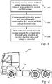
- Fig. 4 is a vehicle 400 comprising a measurement system 100 for a power system according to any of the aforementioned embodiments and examples.
Abstract
Description
- The invention relates to a measurement system and method for determining a status of a power system in an electrical or hybrid vehicle. In particular, the invention relates to a system and method for ensuring the absence of hazardous voltages in a high-voltage system of an electrical vehicle.
- The invention is applicable in electrical and hybrid vehicles within the fields of trucks, buses, industrial construction machines and the like. Although the invention will be described with reference to a truck, the invention is not restricted to this particular vehicle, but may also be used in other electric vehicles.
- In vehicles comprising electrical or hybrid drive systems, it is important to be able to safely disconnect the high-voltage energy source from the other high-voltage vehicle systems, for example for allowing the vehicle to be serviced and repaired in a secure manner. There are typically ways of manually shutting down or otherwise disconnecting the high-voltage system. However, due to the potentially great hazards of working with a high-voltage system that has not been properly shut down, back-up systems for ensuring that no high-voltage components are accessible to a user are desirable.
- Moreover, according to safety standards such as CENELEC - EN 50110, it is required that a secure measurement is performed to confirm the absence of hazardous voltages in the system. Such a secure measurement is often performed by connecting an external device to the vehicle power system and measuring the voltage at a selected location.
- One main safety feature of a typical traction voltage system in a vehicle is to have the traction voltage floating with no galvanic connection to the chassis. However, it is not practically possible to have infinite DC isolation resistance between traction voltage lines and the chassis, and this in itself constitute a risk. The DC isolation can be monitored to increase safety, but capacitances are more difficult to avoid, and such capacitances may contain enough energy to be dangerous. Hence, it's important to make sure that capacitances between traction voltage lines and the chassis (for instance decoupling Y-capacitors on electric machine drives) are sufficiently discharged before work on the vehicle traction voltage system is started.
- Accordingly, it is desirable to further improve the safety of a high-voltage vehicle system.
- An object of the invention is to provide a measurement system for determining safe operating conditions of a high-voltage power system in a vehicle to improve the safety in a high-voltage power system by ensuring that there are no hazardous voltages in the system.
- According to a first aspect of the invention, there is provided a measurement system for determining safe operating conditions of a high-voltage power system of a vehicle. The measurement system comprises: a first voltage measurement unit arranged to measure a first voltage between a positive pole and a negative pole of the power system; a second voltage measurement unit arranged to measure a second voltage between the positive pole and ground of the power system; a third voltage measurement unit arranged to measure a third voltage between a negative pole and ground of the power system; and a measurement system control unit connected to the first, second and third voltage measurement units and configured to compare each of the first, second and third voltage with a corresponding first, second and third voltage threshold value, and if any of the first second or third voltages exceed the corresponding threshold value, provide an indication that a threshold voltage is exceeded.
- The high-voltage power system herein refers to a system for providing electrical power to electrical components of a vehicle. The energy source may be a battery arranged to provide power to an electrical motor for vehicle propulsion, or in the case of a working machine, to an implement of the working machine. The high-voltage system typically operates at voltages over 200V, and often the in the range of 400V to 1000V in order to provide propulsive power for heavy vehicles such as trucks and buses.
- The measurement system is arranged to measure both the pole-to-pole voltage as well as pole-to-ground voltages for both poles in order to ensure that there is no hazardous voltage in the system. The measurements are intended to be performed in decommissioned system to provide safety for an operator. An operator can thereby be ensured that a decommissioned system is safe for performing repairs or other maintenance.
- According to one embodiment of the invention, the control unit is further configured to compare the second voltage to the third voltage, and if a difference between the second and third voltage is higher than a predetermined voltage difference threshold value, provide an indication that there is a voltage asymmetry. By comparing the two pole-to-pole voltages, i.e. the voltage between the respective negative and positive pole and ground, the measurement system is capable of detecting and characterizing asymmetric isolation faults in the high-voltage power system. There are typically capacitances between both poles and ground in the form of so-called class-Y capacitors which are configured to fail open. However, the capacitances may be charged and discharged differently, with different voltages and at different speeds, in particular when there is a fault such as a short circuit somewhere in the system, which in turn can lead to an asymmetry in the two pole-to-chassis voltages. An asymmetry can also occur if the capacitors have deteriorated such that capacitors have a capacitance which deviates from a nominal value.
- Another example of an asymmetric voltage would be if there is a difference in resistance from pole to chassis on positive and negative side, which will lead to a residual voltage when a pole-to-pole discharge is done. Another example is if an isolation monitoring mechanism is aborted during a measurement sequence since it involves active discharge in an asymmetric way.
- In a fully functional system, a discharge is typically performed automatically at system shut down. However, in a workshop, defective vehicles are also handled. The system typically comprises means for passive discharge, but which is comparatively quite slow. Regardless of the discharge method, an asymmetric scenario will give a remaining voltage that might be hazardous.
- According to one embodiment of the invention, the second and third voltage measurement units are arranged to measure at an energy storage of the high-voltage power system. The energy storage may for example being a battery for providing power to a propulsion system in an electric or hybrid vehicle, and the power system may comprise one or more batteries.
- According to one embodiment of the invention, the control unit is further configured to control the first second and third voltage measurement units to repeatedly and simultaneously measure the respective first, second and third voltage. The measurements may for example be performed repeatedly as long as work is being performed, thereby ensuring that an operator is safe when working with the vehicle. The voltage measurement units may for example be configured to repeatedly measure the first, second and third voltages with a fixed interval, wherein the fixed interval is in the range of 10ms to 500ms. By measuring each of the first, second and third voltages simultaneously it can be ensured that an instantaneous system state is characterized.
- According to one embodiment of the invention, the first, second and third voltage measurement units are integral parts of a high voltage system of a vehicle. As outlined above, the second and third voltage measurement units, i.e. for measuring the pole to chassis voltages may be voltage measurement units used for measuring an output voltage of the battery. The first voltage measurement unit for measuring the pole-to-pole voltage may be integrated in an electric motor drive unit.
- There is also provided a high-voltage power system for a vehicle comprising: a high-voltage energy source; a high-voltage system; and a measurement system and a vehicle comprising such a high-voltage power system according to claim 7.
- According to a second aspect of the invention, there is provided a method for determining safe operating conditions of a high-voltage power system in a vehicle using a measurement system. The measurement system comprising: a first voltage measurement unit arranged to measure a first voltage between a positive pole and a negative pole of the power system; a second voltage measurement unit arranged to measure a second voltage between the positive pole and ground of the power system; a third voltage measurement unit arranged to measure a third voltage between a negative pole (106) and ground of the power system; The method comprises: controlling the first, second and third voltage measurement units to measure a respective first, second and third voltage; comparing each of the first, second and third voltage with a corresponding first, second and third voltage threshold value; and if any of the first second and third voltage exceeds the corresponding threshold value, providing an indication that a threshold voltage is exceeded.
- Effects and features of this second aspect of the present invention are largely analogous to those described above in connection with the first aspect of the invention.
- Further advantages and advantageous features of the invention are disclosed in the following description and in the dependent claims.
- With reference to the appended drawings, below follows a more detailed description of embodiments of the invention cited as examples.
- In the drawings:
-
Fig. 1 is a schematic illustration of a measurement system for a high-voltage power system in a vehicle according to an embodiment of the invention; -
Fig. 2 is a schematic illustration of a measurement system for a high-voltage power system in a vehicle according to an embodiment of the invention; -
Fig. 3 is a flow chart outlining a method of controlling a measurement system for a high-voltage power system in a vehicle according to an embodiment of the invention, and -
Fig. 4 is a vehicle comprising a measurement system according to an embodiment of the invention. - In the present detailed description, various embodiments of a measurement system for a high-voltage power system according to the present invention are mainly discussed with reference to a power system in a truck. It should however be noted that this by no means limits the scope of the present invention since the described invention is equally applicable in other types of vehicles such as cars, buses and construction vehicles. The described safety circuit may also be used in marine applications such as boats and ships, and in other applications comprising a high-voltage power source and a high-voltage system.
-
Fig. 1 is a circuit schematic illustrating ameasurement system 100 for determining a safe operating conditions of a high-voltage power system in a vehicle. The measurement system comprises a firstvoltage measurement unit 102, a second voltage measurement unit 104 and a third voltage measurement unit 106. The firstvoltage measurement unit 102 is arranged to measure a first voltage between apositive pole 108 and anegative pole 110 of the power system. The second voltage measurement unit 104 arranged to measure a second voltage between thepositive pole 108 and ground 112 of the power system and the third voltage measurement unit 106 is arranged to measure a third voltage between thenegative pole 110 and ground 112 of the power system. The ground potential of the vehicle may be defined by the chassis, and the second and third voltage measurement units 104, 106 are thereby connected between a respective pole and the vehicle chassis. - The measurement system further comprises a measurement
system control unit 114 connected to the first, second and thirdvoltage measurement units 102, 104, 106 and is configured to compare each of the first, second and third voltage with a corresponding first, second and third voltage threshold value. If any of the first second or third voltages exceed the corresponding threshold value, an indication is provided that a threshold voltage is exceeded. - The measurement
system control unit 114 may include a microprocessor, microcontroller, programmable digital signal processor or another programmable device. The control unit may also, or instead, include an application specific integrated circuit, a programmable gate array or programmable array logic, a programmable logic device, or a digital signal processor. Where the control unit includes a programmable device such as the microprocessor, microcontroller or programmable digital signal processor mentioned above, the processor may further include computer executable code that controls operation of the programmable device. The functionality of the measurementsystem control unit 114 may also be integrated in one or more general purpose or dedicated ECUs (electronic control units) of the vehicle. - The indication that a threshold voltage is exceeded may for example be provided by a notification unit configured to provide a visual and/or audible indication to an operator. The notification unit may be a separate unit configured to sound an alarm or to flash a light if a threshold voltage is exceeded. A notification may also be provided by a horn, a buzzer, or lights of the vehicle.
- As schematically illustrated in
Fig. 1 , themeasurement system 100 may further comprise adisplay device 116 arranged to be visible to an operator, wherein the display is configured to show the first, second and third voltages. The operator can thus monitor the voltages in person to ensure that the threshold voltages are not exceeded, and that system is safe. The display may be mounted on the vehicle. It is also possible to provide a remote monitoring device where the vehicle sends the measured voltages to an external device. The external device may be a dedicated display device, or it may be provided in the form of functionality integrated in a smartphone, a tablet or the like in the form of an app. Thereby, by providing a notification to a user that a voltage threshold is exceeded, the user can be alerted that there may be a hazardous voltage in the vehicle and appropriate precautions can be taken. - In an example embodiment, the voltage threshold value may be in the range of 30V to 50V, such as 40V. According to current standards for vehicle implementation, it may be required that a system voltage in a decommissioned system does not exceed 60V. However, it may be desirable to set the threshold voltage lower than 60V since also lower voltages can be indicative on a fault in the system. The definition of a safe operating voltage for an operator is the same whether it concerns a pole-to-pole or a pole-to-ground voltage. However, if a capacitor between a pole and ground is large, the capacitor may hold sufficient energy for a harmful discharge also at voltage lower than a safe operating voltage. Accordingly, in some implementations it may desirable to have a voltage threshold value for the pole-to-ground voltage which is lower than a voltage threshold value for the pole-to-pole voltage.
- The measurement
system control unit 114 is configured to control the first, second and thirdvoltage measurement units 102, 104, 106 to measure a voltage to determine a pole-to-pole voltage, Up-p, and a respective voltage between the positive andnegative poles system control unit 114 to the appropriate vehicle system. - To provide continuous monitoring in order to ensure the safety of the operator also during work on the vehicle, the voltages may be measured or sampled repeatedly, such as ever 10ms. To prevent that the system provides an indication or alert for transient voltages, it may be required that a plurality of consecutive voltages exceed the corresponding voltage threshold value, such as three consecutive voltages.
-
Fig. 2 schematically illustrates anexample power system 200 comprising themeasurement system 100 described above with reference toFig. 1 . Thepower system 200 comprises at least one high-voltage energy source 202. In the illustrated example, the high-voltage energy source 202 comprises a plurality of battery packs connected to the high-voltage system 204 via ajunction box 206. The high-voltage system 204 is here illustrated as comprising twoelectrical machines 208a-b for providing vehicle propulsion, each electrical machine being controlled by a corresponding electricmotor drive unit 210a-b. A voltage measurement unit for may for example be integrated in the electricmotor drive unit 210a-b. A voltage measurement unit may also be integrated in a DC-DC converter 212 of the high voltage system. - Moreover, the pole-to-chassis measurements which are compared to corresponding threshold voltages may be performed both at
batteries 202 of the system and/or centrally for the whole high-voltage system. A central voltage measurement may for example be performed by a traction voltage monitoring unit (TVMU). -
Fig. 3 is a flow chart outlining the general steps of a method which may be performed by the above described measurementsystem control unit 110. The method comprises controlling 300 the first, second and thirdvoltage measurement units 102, 104, 106 to measure a respective first, second and third voltage Up-p, Up+, Up-, and comparing 302 each of the first, second and third voltages with a corresponding first, second and third voltage threshold value. If any of the first second and third voltage exceeds the corresponding threshold value, an indication is provided 304 that a threshold voltage is exceeded. -
Fig. 4 is avehicle 400 comprising ameasurement system 100 for a power system according to any of the aforementioned embodiments and examples. - It is to be understood that the present invention is not limited to the embodiments described above and illustrated in the drawings; rather, the skilled person will recognize that many changes and modifications may be made within the scope of the appended claims.
Claims (15)
- A measurement system (100) for determining safe operating conditions of a high-voltage power system of a vehicle (400), the measurement system comprising:a first voltage measurement unit (102) arranged to measure a first voltage between a positive pole (108) and a negative pole (110) of the power system;a second voltage measurement unit (104) arranged to measure a second voltage between the positive pole and ground (112) of the power system;a third voltage measurement unit (106) arranged to measure a third voltage between the negative pole and ground of the power system; anda measurement system control unit (114) connected to the first, second and third voltage measurement units and configured to compare each of the first, second and third voltage with a corresponding first, second and third voltage threshold value, and if any of the first second or third voltages exceed the corresponding threshold value, provide an indication that a threshold voltage is exceeded.
- The measurement system according to claim 1, wherein the control unit is further configured to compare the second voltage to the third voltage, and if a difference between the second and third voltage is higher than a predetermined voltage difference threshold value, provide an indication that there is a voltage asymmetry.
- The measurement system according to claim 1 or 2, wherein the second and third voltage measurement units are arranged to measure at an energy storage of the high-voltage power system.
- The measurement system according to any one of the preceding claims, wherein the control unit is further configured to control the first second and third voltage measurement units to repeatedly and simultaneously measure the respective first, second and third voltage.
- The measurement system according to claim 4, wherein the control unit is further configured to control the first, second and third voltage measurement units to repeatedly measure the respective first, second and third voltage with a fixed interval, wherein the fixed interval is in the range of 10ms to 500ms.
- The measurement system according to any one of the preceding claims, wherein the first, second and third voltage measurement units are integral parts of a high voltage system of a vehicle.
- A high-voltage power system (200) for a vehicle comprising:a high-voltage energy source (202);a high-voltage system (204); anda measurement system (100) according to any one of the preceding claims.
- A vehicle (400) comprising a high-voltage power system according to claim 7.
- Method for determining safe operating conditions of a high-voltage power system (200) in a vehicle (400) using a measurement system (100), the measurement system comprising:a first voltage measurement unit (102) arranged to measure a first voltage between a positive pole (108) and a negative pole (110) of the power system;a second voltage measurement unit (104) arranged to measure a second voltage between the positive pole and ground (112) of the power system;a third voltage measurement unit (106) arranged to measure a third voltage between the negative pole and ground of the power system; wherein the method comprises:controlling (300) the first, second and third voltage measurement units to measure a respective first, second and third voltage;comparing (302) each of the first, second and third voltage with a corresponding first, second and third voltage threshold value; andif any of the first second and third voltage exceeds the corresponding threshold value, providing (304) an indication that a threshold voltage is exceeded.
- The method according to claim 9, further comprising comparing the second voltage to the third voltage, and if a difference between the second and third voltage is higher than a predetermined voltage difference threshold value, providing an indication that there is a voltage asymmetry.
- The method according to claim 9 or 10, further comprising simultaneously measuring the first, second and third voltages.
- The method according to any one of claims 9 to 11, further comprising measuring the respective first, second and third voltages repeatedly and with a fixed interval.
- The method according to any one of claims 9 to 12, further comprising providing an indication that a threshold voltage is exceeded only if a predetermined number of consecutive measured voltages exceed the corresponding voltage threshold value.
- The method according to any one of claims 9 to 13, further comprising determining that the vehicle power system is in a passive state.
- The method according to any one of claims 9 to 14, further comprising, if any of the first, second or third voltages exceed the corresponding threshold value, providing a visual and/or audible alert to notify an operator that the high-voltage power system is unsafe.
Priority Applications (3)
| Application Number | Priority Date | Filing Date | Title |
|---|---|---|---|
| EP20205941.6A EP3995342A1 (en) | 2020-11-05 | 2020-11-05 | Measurement system and method for determining a status of a power system in a vehicle using the measurement system |
| CN202111262951.2A CN114441844A (en) | 2020-11-05 | 2021-10-28 | Measurement system and method for determining the state of an electrical system in a vehicle using the measurement system |
| US17/453,112 US20220137148A1 (en) | 2020-11-05 | 2021-11-01 | Measurement system and method for determining a status of a power system in a vehicle using the measurement system |
Applications Claiming Priority (1)
| Application Number | Priority Date | Filing Date | Title |
|---|---|---|---|
| EP20205941.6A EP3995342A1 (en) | 2020-11-05 | 2020-11-05 | Measurement system and method for determining a status of a power system in a vehicle using the measurement system |
Publications (1)
| Publication Number | Publication Date |
|---|---|
| EP3995342A1 true EP3995342A1 (en) | 2022-05-11 |
Family
ID=73138708
Family Applications (1)
| Application Number | Title | Priority Date | Filing Date |
|---|---|---|---|
| EP20205941.6A Pending EP3995342A1 (en) | 2020-11-05 | 2020-11-05 | Measurement system and method for determining a status of a power system in a vehicle using the measurement system |
Country Status (3)
| Country | Link |
|---|---|
| US (1) | US20220137148A1 (en) |
| EP (1) | EP3995342A1 (en) |
| CN (1) | CN114441844A (en) |
Citations (4)
| Publication number | Priority date | Publication date | Assignee | Title |
|---|---|---|---|---|
| US20040189330A1 (en) * | 2003-01-09 | 2004-09-30 | Ulrich Herb | Circuit and method for detecting insulation faults |
| DE102010006108A1 (en) * | 2010-01-29 | 2011-08-04 | Bayerische Motoren Werke Aktiengesellschaft, 80809 | Isolation determining device for use in propulsion net of e.g. hybrid car, has resistors connected with supply conduit of isolated terra-system over switches, where isolation failure is determined based on signal sequence in system |
| US20130221997A1 (en) * | 2010-06-15 | 2013-08-29 | Vicente Garcia Alvarrez | Method and device for monitoring the insulation resistance in an ungrounded electrical network |
| US20170106754A1 (en) * | 2014-03-28 | 2017-04-20 | Continental Automotive Gmbh | Device and method for monitoring an electrical insulation in a vehicle electrical system |
Family Cites Families (3)
| Publication number | Priority date | Publication date | Assignee | Title |
|---|---|---|---|---|
| US8013548B2 (en) * | 2008-10-14 | 2011-09-06 | General Electric Company | System, vehicle and related method |
| US8538617B2 (en) * | 2011-06-15 | 2013-09-17 | GM Global Technology Operations LLC | Mode selection technique for onboard energy management |
| WO2017004182A1 (en) * | 2015-07-02 | 2017-01-05 | Hubbell Incorporated | Voltage measurement and wireless communication system |
-
2020
- 2020-11-05 EP EP20205941.6A patent/EP3995342A1/en active Pending
-
2021
- 2021-10-28 CN CN202111262951.2A patent/CN114441844A/en active Pending
- 2021-11-01 US US17/453,112 patent/US20220137148A1/en active Pending
Patent Citations (4)
| Publication number | Priority date | Publication date | Assignee | Title |
|---|---|---|---|---|
| US20040189330A1 (en) * | 2003-01-09 | 2004-09-30 | Ulrich Herb | Circuit and method for detecting insulation faults |
| DE102010006108A1 (en) * | 2010-01-29 | 2011-08-04 | Bayerische Motoren Werke Aktiengesellschaft, 80809 | Isolation determining device for use in propulsion net of e.g. hybrid car, has resistors connected with supply conduit of isolated terra-system over switches, where isolation failure is determined based on signal sequence in system |
| US20130221997A1 (en) * | 2010-06-15 | 2013-08-29 | Vicente Garcia Alvarrez | Method and device for monitoring the insulation resistance in an ungrounded electrical network |
| US20170106754A1 (en) * | 2014-03-28 | 2017-04-20 | Continental Automotive Gmbh | Device and method for monitoring an electrical insulation in a vehicle electrical system |
Non-Patent Citations (1)
| Title |
|---|
| ANONYMOUS: "Laboratory Test Procedure For FMVSS 305, Electric Powered Vehicles: Electrolyte Spillage And Electrical Shock Protection", TEST PROCEDURES, vol. TP-305-01, 11 September 2008 (2008-09-11), US, pages 1 - 46, XP055794530, Retrieved from the Internet <URL:https://www.nhtsa.gov/sites/nhtsa.dot.gov/files/tp-305-01.pdf> [retrieved on 20210412] * |
Also Published As
| Publication number | Publication date |
|---|---|
| CN114441844A (en) | 2022-05-06 |
| US20220137148A1 (en) | 2022-05-05 |
Similar Documents
| Publication | Publication Date | Title |
|---|---|---|
| CN105667324B (en) | The maintenance direction method of electronic component leaks in BMS diagnosis and vehicle driving state | |
| US9057750B2 (en) | Test of a testing device for determining a voltage state of a high-voltage vehicle electrical system | |
| US7709977B2 (en) | Method and arrangement for controlling a switching connection between the electrical outputs of a fuel cell and an isolated electrical network | |
| EP2664480B1 (en) | System for servicing high voltage battery packs | |
| KR101234059B1 (en) | Apparatus and Method for diagnosis of cell balancing unit | |
| US9696385B2 (en) | Apparatus for detecting the state of a rechargeable battery to be checked | |
| KR101664594B1 (en) | System and method for diagnosing insulation-breakdown of vehicel component | |
| KR101316186B1 (en) | Drive control method of vehicle by detected dielectric breakdown | |
| KR101714243B1 (en) | Apparatus and method for diagonising current sensor of green car | |
| KR20180023140A (en) | Power Relay Assembly fault controlling system and the method thereof | |
| KR20150119724A (en) | Battery Discharge Preventing System and Method Using the Same for Hybrid Vehicle | |
| KR20140072522A (en) | System and method for managing battery and vehicle equipped with the same system | |
| KR101558736B1 (en) | Method for diagnosing the failure of vehicle using output impedance of DC/DC Converter | |
| KR101574429B1 (en) | The detecting device of insulation resistance and the method for eco-friendly vehicles | |
| EP3995342A1 (en) | Measurement system and method for determining a status of a power system in a vehicle using the measurement system | |
| US20190031030A1 (en) | Method for Operating an Electrical System of a Motor Vehicle, and Motor Vehicle | |
| KR101490716B1 (en) | Battery management apparatus and method | |
| EP2889174A1 (en) | Battery management device and power supplying system including the same, electrically isolating each battery unit upon fault | |
| JP2017034939A (en) | Power control unit | |
| CN114248626B (en) | Vehicle high-voltage discharge control method and device and vehicle | |
| EP3988946A1 (en) | Measurement system and method for determining a status of a power system in a vehicle using the measurement system | |
| CN112654523B (en) | Method for operating a battery module | |
| KR102207054B1 (en) | Battery Module Connection Diagnostic Equipment | |
| KR20110136468A (en) | Malfunction preventing electrical control unit for lowering voltage of main battery and driving method thereof | |
| CN112467698A (en) | Safety protection method of relay and electric vehicle |
Legal Events
| Date | Code | Title | Description |
|---|---|---|---|
| PUAI | Public reference made under article 153(3) epc to a published international application that has entered the european phase |
Free format text: ORIGINAL CODE: 0009012 |
|
| STAA | Information on the status of an ep patent application or granted ep patent |
Free format text: STATUS: THE APPLICATION HAS BEEN PUBLISHED |
|
| AK | Designated contracting states |
Kind code of ref document: A1 Designated state(s): AL AT BE BG CH CY CZ DE DK EE ES FI FR GB GR HR HU IE IS IT LI LT LU LV MC MK MT NL NO PL PT RO RS SE SI SK SM TR |
|
| STAA | Information on the status of an ep patent application or granted ep patent |
Free format text: STATUS: REQUEST FOR EXAMINATION WAS MADE |
|
| 17P | Request for examination filed |
Effective date: 20221025 |
|
| RBV | Designated contracting states (corrected) |
Designated state(s): AL AT BE BG CH CY CZ DE DK EE ES FI FR GB GR HR HU IE IS IT LI LT LU LV MC MK MT NL NO PL PT RO RS SE SI SK SM TR |