EP3995252A1 - Wiring terminal clamping jaw - Google Patents
Wiring terminal clamping jaw Download PDFInfo
- Publication number
- EP3995252A1 EP3995252A1 EP20837283.9A EP20837283A EP3995252A1 EP 3995252 A1 EP3995252 A1 EP 3995252A1 EP 20837283 A EP20837283 A EP 20837283A EP 3995252 A1 EP3995252 A1 EP 3995252A1
- Authority
- EP
- European Patent Office
- Prior art keywords
- clamping
- connecting terminal
- component
- rotation angle
- limit part
- Prior art date
- Legal status (The legal status is an assumption and is not a legal conclusion. Google has not performed a legal analysis and makes no representation as to the accuracy of the status listed.)
- Pending
Links
Images



Classifications
-
- B—PERFORMING OPERATIONS; TRANSPORTING
- B25—HAND TOOLS; PORTABLE POWER-DRIVEN TOOLS; MANIPULATORS
- B25J—MANIPULATORS; CHAMBERS PROVIDED WITH MANIPULATION DEVICES
- B25J15/00—Gripping heads and other end effectors
- B25J15/0052—Gripping heads and other end effectors multiple gripper units or multiple end effectors
- B25J15/0061—Gripping heads and other end effectors multiple gripper units or multiple end effectors mounted on a modular gripping structure
-
- B—PERFORMING OPERATIONS; TRANSPORTING
- B25—HAND TOOLS; PORTABLE POWER-DRIVEN TOOLS; MANIPULATORS
- B25J—MANIPULATORS; CHAMBERS PROVIDED WITH MANIPULATION DEVICES
- B25J15/00—Gripping heads and other end effectors
- B25J15/02—Gripping heads and other end effectors servo-actuated
- B25J15/0253—Gripping heads and other end effectors servo-actuated comprising parallel grippers
-
- B—PERFORMING OPERATIONS; TRANSPORTING
- B25—HAND TOOLS; PORTABLE POWER-DRIVEN TOOLS; MANIPULATORS
- B25J—MANIPULATORS; CHAMBERS PROVIDED WITH MANIPULATION DEVICES
- B25J19/00—Accessories fitted to manipulators, e.g. for monitoring, for viewing; Safety devices combined with or specially adapted for use in connection with manipulators
- B25J19/02—Sensing devices
- B25J19/021—Optical sensing devices
-
- B—PERFORMING OPERATIONS; TRANSPORTING
- B25—HAND TOOLS; PORTABLE POWER-DRIVEN TOOLS; MANIPULATORS
- B25J—MANIPULATORS; CHAMBERS PROVIDED WITH MANIPULATION DEVICES
- B25J9/00—Program-controlled manipulators
- B25J9/10—Program-controlled manipulators characterised by positioning means for manipulator elements
- B25J9/1005—Program-controlled manipulators characterised by positioning means for manipulator elements comprising adjusting means
- B25J9/101—Program-controlled manipulators characterised by positioning means for manipulator elements comprising adjusting means using limit-switches, -stops
-
- B—PERFORMING OPERATIONS; TRANSPORTING
- B25—HAND TOOLS; PORTABLE POWER-DRIVEN TOOLS; MANIPULATORS
- B25J—MANIPULATORS; CHAMBERS PROVIDED WITH MANIPULATION DEVICES
- B25J9/00—Program-controlled manipulators
- B25J9/10—Program-controlled manipulators characterised by positioning means for manipulator elements
- B25J9/14—Program-controlled manipulators characterised by positioning means for manipulator elements fluid
- B25J9/144—Linear actuators
Definitions
- the disclosure relates to the field of power distribution, and more particularly to a clamping jaw of connecting terminal.
- An object of the present disclosure is to solve at least above problems, and to provide, at least, the advantages that will be described later.
- Another object of the present disclosure is to provide a clamping jaw of connecting terminal, which can solve the problem of clamping of different types and models of connecting terminals, and even clamping of special types of connecting terminals by one clamping device.
- a clamping jaw of connecting terminal comprising: a rotary cylinder component, which is configured for achieving different swing angles for clamping different types of connecting terminals; a pneumatic clamper component, which is connected with the rotary cylinder component and makes open and close movement; a terminal clamping arm component, which is connected with the pneumatic clamper component, moves with the pneumatic clamper component, and is configured for clamping a connecting terminal; wherein the rotary cylinder component comprises:
- the initial state limit part is a first limit block, which is provided with a semi-cylindrical clamping groove, through which a clamping component with a protrusion can be clamped.
- the first positioning pin shaft realizes its concertina movement through a needle-shaped cylinder mounted on the bearing mounting plate through a needle-shaped cylinder mounting seat.
- the clamping jaw of connecting terminal further comprising a clamping head component, which is used for connecting the rotary cylinder component to a mechanical hand, and the clamping head component comprises:
- the rotation of the rotating cylinder 31 until the connecting terminal is positioned is completed by the following process: S31, a control mechanism recognizing the type of connecting terminals to be installed, and clamping two types of connecting terminals to be installed at one time; wherein a rotation angle is the first rotation angle when a first type of connecting terminal is installed, and a rotation angle is the second rotation angle when a second type of connecting terminal is installed; S32, the control mechanism selecting limit parts according to the types of connecting terminals to be installed, the first state limit part starting to work and the rotating cylinder 31 being positioned at the first rotation angle if the connecting terminal to be installed is the first type; and the second state limit part starting to work and the rotating cylinder 31 being positioned at the second rotation angle if the connecting terminal to be installed is the second type; S4, clamping the connecting terminal: disconnecting air supply for the rotating cylinder 31, moving the clamping jaw of the connecting terminal downward along the Z axis, contacting the connecting terminal to be installed with the guiding rail, separating the pneumatic clamper component from the first state limit
- connecting terminals there are various types of connecting terminals, and various types of connecting terminals are clamped by different devices or multiple mechanical hands in prior art.
- One clamping jaw of connecting terminal of the present disclosure can clamp various types of connecting terminals without requiring multiple mechanical hands to operate, and has more flexible operation.
- the second state limit part is a first positioning pin shaft 40, which is a cylinder or a quasi-cylinder that is stretchable relative to the bearing mounting plate 41.
- the first positioning pin shaft 40 is installed on the bearing mounting plate 41 through a positioning pin shaft seat 39, and is located between the buffer block 34 and the first limit block 38.
- the rotation angle of the rotating cylinder 31 is positioned at 15 degrees, and when the first positioning pin shaft 40 draws back, the rotating cylinder 31 can be rotated to 83-85 degrees.
- the first positioning pin shaft 40 realizes its concertina movement through a needle-shaped cylinder 43, and the needle-shaped cylinder 43 is mounted on the bearing mounting plate 41 through a needle-shaped cylinder mounting seat 42.
- the needle-shaped cylinder 43 realizes the automatic operation of the second state limit part, and improves the operation efficiency.
- components on the pneumatic clamper component 50 are clamped with the first state limit part and the second state limit part to realize the positioning of the rotating cylinder 32 at different rotation angles, so that the entire device has higher stability and flexibility.
- the POM block 63 is a plurality of independent sub-blocks that are stacked.
- the POM block 63 includes 3-12 independent sub-blocks that are stacked.
- the multi-layer POM block 63 moves back and forward with the terminal clamping arm 61, and the terminal clamping arm 61 plays a guiding role to achieve the purpose of conformal clamping and preventing the connecting terminal from falling off.
- the setting of multiple independent sub-blocks allows the conformal clamping from the point to the surface to prevent the connecting terminal from falling off.
Landscapes
- Engineering & Computer Science (AREA)
- Robotics (AREA)
- Mechanical Engineering (AREA)
- Manipulator (AREA)
- Jigs For Machine Tools (AREA)
Abstract
Description
- The disclosure relates to the field of power distribution, and more particularly to a clamping jaw of connecting terminal.
- With the rapid development of the power distribution industry,, automatically installing a connecting terminal on a guide rail has became inevitable trend in the development of the power distribution industry. However, due to different types and models of the connecting terminal, when the connecting terminal is automatically installed on the guide rail, a technical problem that will be confronted is how to realize clamping of different types and models of connecting terminals, and even clamping of special types of connecting terminals by one clamping device.
- An object of the present disclosure is to solve at least above problems, and to provide, at least, the advantages that will be described later.
- Another object of the present disclosure is to provide a clamping jaw of connecting terminal, which can solve the problem of clamping of different types and models of connecting terminals, and even clamping of special types of connecting terminals by one clamping device.
- In order to achieve the above objects and other advantages, the present disclosure provides a clamping jaw of connecting terminal, comprising: a rotary cylinder component, which is configured for achieving different swing angles for clamping different types of connecting terminals; a pneumatic clamper component, which is connected with the rotary cylinder component and makes open and close movement; a terminal clamping arm component, which is connected with the pneumatic clamper component, moves with the pneumatic clamper component, and is configured for clamping a connecting terminal; wherein the rotary cylinder component comprises:
- a fixing plate component, which comprises a bearing mounting plate;
- a rotating shaft, which is mounted on the bearing mounting plate and provides a driving force through a rotating cylinder;
- an initial state limit part, which is installed on the bearing mounting plate, is configured for realizing positioning of the rotating cylinder in an initial state of rotation;
- a first state limit part, which is installed on the bearing mounting plate, is configured for realizing positioning of the rotating cylinder in a first rotation angle, the first rotation angle being rotated clockwise by a predetermined angle relative to the initial state; and
- a second state limit part, which is movably installed on the bearing mounting plate, and has a working position and a non-working position relative to the bearing mounting plate; wherein when the second state limit part is in the working position, it is configured for realizing positioning of the rotating cylinder in a second rotation angle, and when the second state limit part is in the non-working position, it is configured for realizing the positioning of the rotating cylinder in the first rotation angle; wherein the second rotation angle is smaller than the first rotation angle.
- Preferably, the first rotation angle is 83-85 degrees, and the second rotation angle is 15 degrees.
- Preferably, the initial state limit part is a first limit block, which is provided with a semi-cylindrical clamping groove, through which a clamping component with a protrusion can be clamped.
- Preferably, the first state limit part is a buffer block, which is provided with a cylinder or a quasi-cylinder.
- Preferably, the second state limit part is a first positioning pin shaft, which is a cylinder or a quasi-cylinder that is stretchable relative to the bearing mounting plate.
- Preferably, the first positioning pin shaft realizes its concertina movement through a needle-shaped cylinder mounted on the bearing mounting plate through a needle-shaped cylinder mounting seat.
- Preferably, the pneumatic clamper component comprises:
- a pneumatic clamper mounting plate, which is connected with the rotary cylinder component, makes open and close movement, and moves with the rotating cylinder component;
- a pneumatic clamper, which is mounted on the pneumatic clamper mounting plate, and drives the terminal clamping arm component to move;
- a second limit block, which is mounted on the pneumatic clamper mounting plate, and cooperates with the first state limit part and the second state limit part to realize positioning of the rotating cylinder in the first rotation angle and the positioning of the rotating cylinder in the second rotation angle, respectively; and
- a second positioning pin shaft, which is mounted on the pneumatic clamper mounting plate, and cooperates with the initial state limit part to realize positioning of the rotating cylinder in the initial state of rotation.
- Preferably, the terminal clamping arm component comprises:
- a terminal clamping arm, which is fixedly connected with the pneumatic clamper;
- a POM block, which is installed at a lower part of the terminal clamping arm and protruds to a side where the connecting terminal is clamped.
- Preferably, a mounting column is arranged at the lower part of the terminal clamping arm, and a mounting hole is arranged at the POM block; wherein the mounting hole is sleeved on the mounting column, the POM block can slide relative to the mounting column, and a sliding direction is parallel to a movement direction of the pneumatic clamper. A rubber block is arranged between the mounting hole and the mounting column and at the side where the connecting terminal is clamped, and is configured for filling a gap between the POM block and the terminal clamping arm. At the gap between the POM block and the terminal clamping arm, the compressed rubber block has an inconsistent length when the connecting terminal is clamped, so that the POM block can wraps the connecting terminal to achieve an effect of conformal clamping without falling off.
- Preferably, the POM block is a plurality of independent sub-blocks that are stacked. When clamping, the multi-layer POM block moves back and forward with the terminal clamping arm, and the terminal clamping arm plays a guiding role to achieve the purpose of conformal clamping and preventing the connecting terminal from falling off.
- Preferably, the clamping jaw of connecting terminal further comprising a clamping head component, which is used for connecting the rotary cylinder component to a mechanical hand, and the clamping head component comprises:
- a vertical plate, which is fixed on the rotary cylinder component;
- a guiding seat, which is fixed on the mechanical hand and arranged in parallel with the vertical plate;
- an optical shaft, which is fixed on the vertical plate, is sleeved with a spring, and is slidably penetrated on the guiding seat;
- a fixing block, which is fixed on the optical shaft, the fixing block and the vertical plate being located on both sides of the guiding seat, respectively;
- a light blocking plate, which is installed between the vertical plate and the fixing block, and is provided with a notch; and
- a photoelectric switch, which is installed on the guiding seat, and can be triggered by the notch on the light blocking plate when the vertical plate compresses the spring in place.
- The disclosure includes at least the following substantial improvements and beneficial effects.
- 1. The clamping jaw of connecting terminal of the disclosure can solve the problem of clamping of different types and models of connecting terminals, and even clamping of special types of connecting terminals by one clamping device; can also easily clamp large-size and complex-shaped connecting terminals that are not easy to be clamped.
- 2. The clamping jaw of connecting terminal of the disclosure can be connected to a PLC control system to realize the purpose of automatic clamping of the connecting terminal.
- 3. The clamping jaw of connecting terminal of the disclosure has compact mechanical structure and flexible operation, and is suitable for large-scale promotion and use.
- Other advantages, objects, and features of the present disclosure will be showed in part through following description, and in part will be understood by those skilled in the art from study and practice of the present disclosure.
-
-
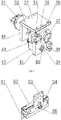
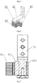
Fig. 1 is a structural diagram of the disclosure. -
Fig. 2 is a structural diagram of the rotary cylinder component according to a technical solution of the disclosure. -
Fig. 3 is a structural diagram of the pneumatic clamper component according to a technical solution of the disclosure. -
Fig. 4 is a structural diagram of the clamping head component according to a technical solution of the disclosure. -
Fig. 5 is a structural diagram of the clamping head component according to a technical solution of the disclosure. -
Fig. 6 is a structural diagram of the terminal clamping arm component according to a technical solution of the disclosure. -
Fig. 7 is a sectional diagram of the terminal clamping arm component according to a technical solution of the disclosure. -
Fig. 8 is a structural diagram of the mechanical hand according to a technical solution of the disclosure. - The following will clearly and completely describe the technical solutions in the embodiments of the present disclosure with reference to the accompanying drawings in the embodiments of the present disclosure.
- It should be noted that terms such as "having", "including" and "comprising" as used herein do not exclude presence or addition of one or more other elements or combinations thereof.
- As shown in
Fig. 1 , the disclosure provides a clamping jaw of connecting terminal, comprising:
arotary cylinder component 30, which is configured for achieving different swing angles for clamping different types of connecting terminals; apneumatic clamper component 50, which is connected with therotary cylinder component 30 and makes open and close movement; a terminalclamping arm component 60, which is connected with thepneumatic clamper component 50, moves with thepneumatic clamper component 50, and is configured for clamping a connecting terminal. - As shown in
Fig. 1 andFig. 2 , therotary cylinder component 30 comprises: - a fixing plate component, which comprises a
bearing mounting plate 41, a rotatingcylinder fixing plate 44 and a rotatingcylinder top plate 33; wherein the rotatingcylinder top plate 33 is arranged horizontally, and the rotatingcylinder fixing plate 44 and thebearing mounting plate 41 are respectively arranged on opposite sides of the rotatingcylinder top plate 33 and are perpendicular to the rotatingcylinder top plate 33 for forming a gate shape to place components; - a rotating
shaft 37, which is mounted on thebearing mounting plate 41 through a rotatingshaft bearing seat 36 and provides a driving force through a rotatingcylinder 31; wherein the rotatingshaft 37 and the rotatingcylinder 31 are connected by acoupling 32 to transmit a driving force, and thecoupling 32 is arranged under the rotatingcylinder top plate 33 so that the components are compact; - an initial state limit part, which is installed on the
bearing mounting plate 41, is configured for realizing positioning of the rotatingcylinder 31 in an initial state of rotation; wherein the initial state limit part may be a buffer component, a toggle block, a block with a clamping groove, or a manual toggle component; - a first state limit part, which is installed on the
bearing mounting plate 41, is configured for realizing positioning of therotating cylinder 31 in a first rotation angle, the first rotation angle being rotated clockwise by a predetermined angle relative to the initial state, and wherein the first state limit part may be a buffer component, a toggle block, a block with a clamping groove, or a manual toggle component; and - a second state limit part, which is movably installed on the
bearing mounting plate 41, and has a working position and a non-working position relative to thebearing mounting plate 41; wherein when the second state limit part is in the working position, it is configured for realizing positioning of therotating cylinder 31 in a second rotation angle, and when the second state limit part is in the non-working position, it is configured for realizing the positioning of therotating cylinder 31 in the first rotation angle; wherein the second rotation angle is smaller than the first rotation angle; wherein second state limit part may be a manual telescopic column or an automatic telescopic shaft, and wherein the automatic telescopic shaft can realize its telescopic function through an air cylinder, a screw rod or an elastic component. - In the above technical solution, the rotating
cylinder 31 rotates at different angles to realize the clamping of different types of connecting terminals, and a specific process is as follow: S1, initialization: the initial state limit part positioning therotating cylinder 31 to an initial state, and the pneumatic clamper component starting to work; S2, clamping the connecting terminal: a mechanical hand moving a clamping jaw of a connecting terminal along the Y-axis or along the X-axis (if necessary) to the vicinity of a elastic clamp, moving the clamping jaw of the connecting terminal downward along the Z axis, the pneumatic clamper component driving the terminal clamping arm component to clamp the connecting terminal, moving the clamping jaw of the connecting terminal upward along the Z axis and clamping up the connecting terminal to be clamped; S3, transport and rotation of the connecting terminal: moving the clamping jaw of the connecting terminal along the Y axis or along the X axis (if necessary) to the vicinity of a guiding rail, and simultaneously rotating therotating cylinder 31 until the connecting terminal is positioned. The rotation of the rotating cylinder 31 until the connecting terminal is positioned is completed by the following process: S31, a control mechanism recognizing the type of connecting terminals to be installed, and clamping two types of connecting terminals to be installed at one time; wherein a rotation angle is the first rotation angle when a first type of connecting terminal is installed, and a rotation angle is the second rotation angle when a second type of connecting terminal is installed; S32, the control mechanism selecting limit parts according to the types of connecting terminals to be installed, the first state limit part starting to work and the rotating cylinder 31 being positioned at the first rotation angle if the connecting terminal to be installed is the first type; and the second state limit part starting to work and the rotating cylinder 31 being positioned at the second rotation angle if the connecting terminal to be installed is the second type; S4, clamping the connecting terminal: disconnecting air supply for the rotating cylinder 31, moving the clamping jaw of the connecting terminal downward along the Z axis, contacting the connecting terminal to be installed with the guiding rail, separating the pneumatic clamper component from the first state limit part or the second state limit part under the drive of the reaction force of the guiding rail, resetting and rotating the connecting terminal, and clamping the connecting terminal with the guiding rail. - In an actual production, there are various types of connecting terminals, and various types of connecting terminals are clamped by different devices or multiple mechanical hands in prior art. One clamping jaw of connecting terminal of the present disclosure can clamp various types of connecting terminals without requiring multiple mechanical hands to operate, and has more flexible operation.
- In one technical solution, the first rotation angle is 83-85 degrees, and the second rotation angle is 15 degrees. The set angles are inclination angles required when clamping two most common types of connecting terminals.
- As shown in
Fig. 2 , in one technical solution, the initial state limit part is afirst limit block 38, which is provided with a semi-cylindrical clamping groove. A clamping component with a protrusion can be clamped through the clamping groove, which realizes positioning automation. - As shown in
Fig. 2 , in one technical solution, the first state limit part is abuffer block 34, wherein thebuffer block 34 is mounted on thebearing mounting plate 41 through a bufferblock mounting plate 35, and is provided with a cylinder or a quasi-cylinder. Thebuffer block 34 of cylinder or a quasi-cylinder can cooperate with a component with a clamping groove structure to achieve the purpose of automatic positioning - As shown in
Fig. 2 , in one technical solution, the second state limit part is a firstpositioning pin shaft 40, which is a cylinder or a quasi-cylinder that is stretchable relative to thebearing mounting plate 41. The firstpositioning pin shaft 40 is installed on thebearing mounting plate 41 through a positioningpin shaft seat 39, and is located between thebuffer block 34 and thefirst limit block 38. When the firstpositioning pin shaft 40 stretches out, the rotation angle of therotating cylinder 31 is positioned at 15 degrees, and when the firstpositioning pin shaft 40 draws back, the rotatingcylinder 31 can be rotated to 83-85 degrees. - As shown in
Fig. 2 , in one technical solution, the firstpositioning pin shaft 40 realizes its concertina movement through a needle-shapedcylinder 43, and the needle-shapedcylinder 43 is mounted on thebearing mounting plate 41 through a needle-shapedcylinder mounting seat 42. The needle-shapedcylinder 43 realizes the automatic operation of the second state limit part, and improves the operation efficiency. - As shown in
Fig. 1 andFig. 3 , in one technical solution, thepneumatic clamper component 50 is connected with therotary cylinder component 30 to realize the movement of the terminalclamping arm component 60. Thepneumatic clamper component 50 comprises: - a pneumatic
clamper mounting plate 53, which is connected with therotary cylinder component 30, specifically the pneumaticclamper mounting plate 53 being provided with a mounting hole, which is connected to arotating shaft 37 in therotary cylinder component 30; - a
pneumatic clamper 52, which is mounted on the pneumaticclamper mounting plate 53, and drives the terminal clampingarm component 60 to move; wherein the terminal clampingarm component 60 is connected with thepneumatic clamper 52 through a terminal clamping armcomponent mounting plate 51; - a
second limit block 54, which is mounted on the pneumaticclamper mounting plate 53, and cooperates with the first state limit part to realize positioning of therotating cylinder 31 in the first rotation angle; specifically, a clamping groove being arranged at thesecond limit block 54 mounted on thepneumatic clamper component 50, the clamping groove being provided with a silicone-containing pad for buffering, when the firstpositioning pin shaft 40 stretching out the rotation angle of therotating cylinder 31 being positioned at 15 degrees and the firstpositioning pin shaft 40 being clamped with thesecond limit block 54 mounted on thepneumatic clamper component 50, and when the firstpositioning pin shaft 40 drawing back thebuffer block 34 being clamped with thesecond limit block 54 mounted on thepneumatic clamper component 50, and the therotating cylinder 31 being allowed to be rotated to 83-85 degrees; and - a second
positioning pin shaft 55, which is mounted on the pneumaticclamper mounting plate 53, and cooperates with the initial state limit part to realize positioning of therotating cylinder 31 in the initial state of rotation; specifically, in the initial state of rotation, thefirst limit block 38 on therotary cylinder component 30 being clamped with the secondpositioning pin shaft 55 on thepneumatic clamper component 50. - In the above technical solution, components on the
pneumatic clamper component 50 are clamped with the first state limit part and the second state limit part to realize the positioning of therotating cylinder 32 at different rotation angles, so that the entire device has higher stability and flexibility. - As shown in
Fig. 6 , in one technical solution, the terminal clampingarm component 60 comprises: - a
terminal clamping arm 61, which is fixedly connected with thepneumatic clamper 52; - a POM (polyformaldehyde)
block 63, which is installed at a lower part of theterminal clamping arm 61 and protrudes to a side where the connecting terminal is clamped. - In the above technical solution, in a clamping process, the
POM block 63 is installed between theterminal clamping arm 61 and a squarepressing plate 64, thePOM block 63 moves back and forward with theterminal clamping arm 61, and theterminal clamping arm 61 plays a guiding role, so as to achieve the purpose of conformal clamping and preventing the connecting terminal from falling off. In the prior art, clamping jaws are generally metal clamping jaws or plastic flexible clamping jaw. The metal clamping jaws have high rigidity and low elastic deformability, which can easily cause damage to the surface of a clamped object; and the flexible clamping jaws, which are mainly made of plastic material, have high elasticity and low rigidity, which cannot meet the requirement of clamping of the connecting terminal. In the technical solution, the clamping jaw made ofPOM block 63 has high rigidity, good elasticity and antifriction and wear resistance, which is not easy to damage the surface of the clamped object. - As shown in
Fig. 6 and Fig. 7 , in one technical solution, a mountingcolumn 610 is arranged at a lower part of theterminal clamping arm 61, and a mounting hole is arranged at thePOM block 63. The mounting hole is sleeved on the mountingcolumn 610, thePOM block 63 can slide relative to the mountingcolumn 610, and a sliding direction is parallel to a movement direction of thepneumatic clamper 52. Arubber block 62 is arranged between the mounting hole and the mountingcolumn 610 and at the side where the connecting terminal is clamped. Specifically, the mountingcolumn 610 is a square column, and the mounting hole is a square hole. The mounting hole is sleeved on the mountingcolumn 610, and the width of the mounting hole is larger than the width of the mountingcolumn 610, so that thePOM block 63 can slide relative to the mountingcolumn 610, and the sliding direction is parallel to a movement direction of thepneumatic clamper 52. Therubber block 62 is arranged between the mounting hole and the mountingcolumn 610 and at the side where the connecting terminal is clamped. In a clamping process, the compression amount of an arc shape on the connecting terminal surface to therubber block 62 is different, which results in different sliding distances of the POM block on the mountingcolumn 610 to realize fit of the POM block and the arc shape on the connecting terminal surface and then to achieve conformal clamping and prevent the connecting terminal from falling off. Therefore, the terminal clampingarm component 60 has wider application range. - In one technical solution, the
POM block 63 is a plurality of independent sub-blocks that are stacked. Preferably, thePOM block 63 includes 3-12 independent sub-blocks that are stacked. In the clamping process, themulti-layer POM block 63 moves back and forward with theterminal clamping arm 61, and theterminal clamping arm 61 plays a guiding role to achieve the purpose of conformal clamping and preventing the connecting terminal from falling off. The setting of multiple independent sub-blocks allows the conformal clamping from the point to the surface to prevent the connecting terminal from falling off. - As shown in
Fig. 1 ,Fig. 4 and Fig. 5 , in one technical solution, the clamping jaw of connecting terminal further comprises a clampinghead component 10, which is used for connecting therotary cylinder component 30 to a mechanical hand, and the clampinghead component 10 comprises: - a
vertical plate 11, which is fixed on therotary cylinder component 30; specifically, wherein thevertical plate 11 is connected to thebearing mounting plate 41 and the rotatingcylinder fixing plate 44 by screws; and thevertical plate 11 may also be preferably provided with alimit column 14 that limits its movement; - a guiding
seat 15, which is fixed on the mechanical hand and arranged in parallel with thevertical plate 11; wherein a three-axis mechanical hand is shown inFig. 6 , which can realizes the X, Y, Z three-axis linkage; - an
optical shaft 18, which is fixed on thevertical plate 11 through an opticalshaft fixing seat 12, is sleeved with aspring 13, and is slidably penetrated on the guidingseat 15; preferably, wherein theoptical shaft 18 is further provided with alinear bearing 16; and more preferably, two sets of theoptical shafts 18 are provided; - a fixing
block 17, which is fixed on theoptical shaft 18, the fixingblock 17 and thevertical plate 11 being located on both sides of the guidingseat 15, respectively; - a
light blocking plate 20, which is installed between thevertical plate 11 and the fixingblock 17, and is provided with anotch 21; and - a
photoelectric switch 19, which is installed on the guidingseat 15, and can be triggered by thenotch 21 on thelight blocking plate 20 when thevertical plate 11 compresses thespring 13 in place, so as to feedback the information of whether the connecting terminal is clamped. - As shown in
Fig. 8 , a clamping process of the mechanical hand is as follow:
S1, initialization: the secondpositioning pin shaft 55 is clamped to thefirst limit block 38. At this time, the angle of therotating cylinder 31 is 0 degree, and thepneumatic clamper 52 is opened. - S2, clamping the connecting terminal: a clamping jaw of a connecting terminal moves along the Y-axis or along the X-axis (if necessary) to the vicinity of the elastic clamp, the clamping jaw of the connecting terminal moves downward along the Z axis, the
pneumatic clamper 52 drives the POM block to to clamp the connecting terminal to be clamped, and the clamping jaw of the connecting terminal moves upward along the Z axis to clamp up the connecting terminal to be clamped. - S3, transport and rotation of the connecting terminal: the clamping jaw of the connecting terminal moves along the Y axis or along the X-axis (if necessary) to the vicinity of the guiding rail, and the
rotating cylinder 31 is simultaneously rotated until the connecting terminal is positioned. - The rotation of the
rotating cylinder 31 until the connecting terminal is positioned is completed by the following process: S31, the control mechanism recognizes the type of connecting terminals to be installed. In the embodiment, there are two types of connecting terminals to be installed, a first type is installed at a rotation angle of 15 degrees, and a second type is installed at a rotation angle of 83-85 degrees. S32, the control mechanism selects limit parts according to the types of connecting terminals to be installed. If the connecting terminal to be installed is the first type, the needle-shapedcylinder 43 is controlled to stretch out and to drive the firstpositioning pin shaft 40 to stretch out , which indicates that the firstpositioning pin shaft 40 is selected for positioning. If the connecting terminal to be installed is the second type, the needle-shapedcylinder 43 is controlled to draw back and to drive the firstpositioning pin shaft 40 to draw back, which indicates that thebuffer block 34 is selected for positioning. S33, the rotatingcylinder 31 is rotated until thesecond limit block 54 is clamped to the firstpositioning pin shaft 40 or thebuffer block 34 to realize that the connecting terminal to be installed can be rotated at an angle of 15 degrees or 83-85 degrees. - S4, clamping the connecting terminal: air supply for the
rotating cylinder 31 is disconnected, and the clamping jaw of the connecting terminal moves downward along the Z axis. When the connecting terminal to be installed is in contact with the guiding rail, thesecond limit block 54 is separated from the firstpositioning pin shaft 40 or thebuffer block 34 under the drive of the reaction force of the guiding rail, the connecting terminal is subjected to reset rotation, and the connecting terminal is clamped with the guiding rail. At this time, the secondpositioning pin shaft 55 is clamped to thefirst limit block 38. - S5, confirming of clamping in place: the rotation during the clamping process of the connecting terminal brings a thrust and displacement in the Y-axis direction. The
vertical plate 11 moves relative to the guidingseat 15, and thenotch 21 on thelight blocking plate 20 can trigger thephotoelectric switch 19 to confirm that the clamping is in place. If thephotoelectric switch 19 is triggered, thepneumatic clamper 52 is opened, and the clamping jaw of the connecting terminal moves upward along the Z axis, return to the step S2 to continue clamping. In the step S4, if the connecting terminal is not in contact with the guiding rail or the connecting terminal is not clamped to the guiding rail due to some reasons, this will cause that thephotoelectric switch 19 can not be triggered. The system will issue an alarm. The clamping jaw of connecting terminal of the disclosure can solve the problem of clamping of different types and models of connecting terminals, and even clamping of special types of connecting terminals by one clamping device; can also easily clamp large-size and complex-shaped connecting terminals that are not easy to be clamped. The clamping jaw of connecting terminal has compact mechanical structure and flexible operation, and is suitable for large-scale promotion and use. - As mentioned above, the disclosure includes at least the following substantial improvements and beneficial effects: 1. The clamping jaw of connecting terminal of the disclosure can solve the problem of clamping of different types and models of connecting terminals, and even clamping of special types of connecting terminals by one clamping device; can also easily clamp large-size and complex-shaped connecting terminals that are not easy to be clamped. 2. The clamping jaw of connecting terminal of the disclosure can be connected to a PLC control system to realize the purpose of automatic clamping of the connecting terminal. 3. The clamping jaw of connecting terminal of the disclosure has compact mechanical structure and flexible operation, and is suitable for large-scale promotion and use.
- Although the embodiments of the present disclosure have been shown and described, those of ordinary skill in the art can understand that various changes, modifications, replacements and variations can be made to these embodiments without departing from the principle and spirit of the present disclosure, and the scope of the present disclosure is defined by the appended claims and their equivalents.
Claims (11)
- A clamping jaw of connecting terminal, comprising: a rotary cylinder component, which is configured for achieving different swing angles for clamping different types of connecting terminals; a pneumatic clamper component, which is connected with the rotary cylinder component and makes open and close movement; a terminal clamping arm component, which is connected with the pneumatic clamper component, moves with the pneumatic clamper component, and is configured for clamping a connecting terminal; wherein the rotary cylinder component comprises:a fixing plate component, which comprises a bearing mounting plate;a rotating shaft, which is mounted on the bearing mounting plate and provides a driving force through a rotating cylinder;an initial state limit part, which is installed on the bearing mounting plate, is configured for realizing positioning of the rotating cylinder in an initial state of rotation;a first state limit part, which is installed on the bearing mounting plate, is configured for realizing positioning of the rotating cylinder in a first rotation angle, the first rotation angle being rotated clockwise by a predetermined angle relative to the initial state; anda second state limit part, which is movably installed on the bearing mounting plate, and has a working position and a non-working position relative to the bearing mounting plate; wherein when the second state limit part is in the working position, it is configured for realizing positioning of the rotating cylinder in a second rotation angle, and when the second state limit part is in the non-working position, it is configured for realizing the positioning of the rotating cylinder in the first rotation angle; wherein the second rotation angle is smaller than the first rotation angle.
- The clamping jaw of connecting terminal according to claim 1, wherein the first rotation angle is 83-85 degrees, and the second rotation angle is 15 degrees.
- The clamping jaw of connecting terminal according to claim 2, wherein the initial state limit part is a first limit block, which is provided with a semi-cylindrical clamping groove, through which a clamping component with a protrusion can be clamped.
- The clamping jaw of connecting terminal according to claim 2, wherein the first state limit part is a buffer block, which is provided with a cylinder or a quasi-cylinder.
- The clamping jaw of connecting terminal according to claim 2, wherein the second state limit part is a first positioning pin shaft, which is a cylinder or a quasi-cylinder that is stretchable relative to the bearing mounting plate.
- The clamping jaw of connecting terminal according to claim 5, wherein the first positioning pin shaft realizes its concertina movement through a needle-shaped cylinder mounted on the bearing mounting plate through a needle-shaped cylinder mounting seat.
- The clamping jaw of connecting terminal according to claim 1, wherein the pneumatic clamper component comprises:a pneumatic clamper mounting plate, which is connected with the rotary cylinder component, makes open and close movement, and moves with the rotating cylinder component;a pneumatic clamper, which is mounted on the pneumatic clamper mounting plate, and drives the terminal clamping arm component to move;a second limit block, which is mounted on the pneumatic clamper mounting plate, and cooperates with the first state limit part and the second state limit part to realize positioning of the rotating cylinder in the first rotation angle and the positioning of the rotating cylinder in the second rotation angle, respectively; anda second positioning pin shaft, which is mounted on the pneumatic clamper mounting plate, and cooperates with the initial state limit part to realize positioning of the rotating cylinder in the initial state of rotation.
- The clamping jaw of connecting terminal according to claim 1, wherein the terminal clamping arm component comprises:a terminal clamping arm, which is fixedly connected with the pneumatic clamper;a POM block, which is installed at a lower part of the terminal clamping arm and protruds to a side where the connecting terminal is clamped.
- The clamping jaw of connecting terminal according to claim 8, wherein a mounting column is arranged at the lower part of the terminal clamping arm, and a mounting hole is arranged at the POM block; wherein the mounting hole is sleeved on the mounting column, the POM block can slide relative to the mounting column, a sliding direction is parallel to a movement direction of the pneumatic clamper, and a rubber block is arranged between the mounting hole and the mounting column and at the side where the connecting terminal is clamped.
- The clamping jaw of connecting terminal according to claim 9, wherein the POM block is a plurality of independent sub-blocks that are stacked.
- The clamping jaw of connecting terminal according to claim 1, further comprising a clamping head component, which is used for connecting the rotary cylinder component to a mechanical hand, wherein the clamping head component comprises:a vertical plate, which is fixed on the rotary cylinder component;a guiding seat, which is fixed on the mechanical hand and arranged in parallel with the vertical plate;an optical shaft, which is fixed on the vertical plate, is sleeved with a spring, and is slidably penetrated on the guiding seat;a fixing block, which is fixed on the optical shaft, the fixing block and the vertical plate being located on both sides of the guiding seat, respectively;a light blocking plate, which is installed between the vertical plate and the fixing block, and is provided with a notch; anda photoelectric switch, which is installed on the guiding seat, and can be triggered by the notch on the light blocking plate when the vertical plate compresses the spring in place.
Applications Claiming Priority (3)
| Application Number | Priority Date | Filing Date | Title |
|---|---|---|---|
| CN201910604446.8A CN110202339B (en) | 2019-07-05 | 2019-07-05 | Binding post clamping jaw |
| CN201921043845.3U CN210099405U (en) | 2019-07-05 | 2019-07-05 | Binding post clamping jaw |
| PCT/CN2020/098095 WO2021004290A1 (en) | 2019-07-05 | 2020-06-24 | Wiring terminal clamping jaw |
Publications (2)
| Publication Number | Publication Date |
|---|---|
| EP3995252A1 true EP3995252A1 (en) | 2022-05-11 |
| EP3995252A4 EP3995252A4 (en) | 2023-08-02 |
Family
ID=74115022
Family Applications (1)
| Application Number | Title | Priority Date | Filing Date |
|---|---|---|---|
| EP20837283.9A Pending EP3995252A4 (en) | 2019-07-05 | 2020-06-24 | Wiring terminal clamping jaw |
Country Status (2)
| Country | Link |
|---|---|
| EP (1) | EP3995252A4 (en) |
| WO (1) | WO2021004290A1 (en) |
Families Citing this family (11)
| Publication number | Priority date | Publication date | Assignee | Title |
|---|---|---|---|---|
| CN113320977B (en) * | 2021-06-04 | 2025-01-21 | 杭州盈天科学仪器有限公司 | Rotating clamping device |
| DE102021129211A1 (en) | 2021-11-10 | 2023-05-11 | Weidmüller Interface GmbH & Co. KG | Gripper fingers for a pick and place machine |
| CN114199886B (en) * | 2021-12-10 | 2023-07-21 | 苏州讯奇软件有限公司 | A product appearance inspection equipment |
| CN114347050A (en) * | 2021-12-17 | 2022-04-15 | 江苏康业金属制品有限公司 | Automatic swing arm manipulator for derusting, polishing and machining based on metal spool |
| CN114311000B (en) * | 2022-01-17 | 2024-06-25 | 浙江精尚数控科技有限公司 | Manipulator clamping device capable of automatically adjusting clamping force |
| CN114799824B (en) * | 2022-04-25 | 2023-10-10 | 深圳市世宗自动化设备有限公司 | Automatic rubber plug removing device |
| CN115258667A (en) * | 2022-08-09 | 2022-11-01 | 苏州佳祺仕信息科技有限公司 | Go up unloading mobile device and go up unloading workstation |
| CN117644424B (en) * | 2024-01-30 | 2024-04-12 | 连云港东睦新材料有限公司 | Rotor processing material loading manipulator |
| CN119408054B (en) * | 2024-09-27 | 2025-12-02 | 玄甲智能科技有限公司 | A flexible gripper device and operating method for pre-embedding micro parts in injection molding |
| CN119408950B (en) * | 2024-11-04 | 2025-11-14 | 上海思客琦智能装备科技股份有限公司 | Battery cell transfer gripper |
| CN119999475B (en) * | 2025-04-08 | 2025-10-17 | 浙江大学 | An end effector for removing abnormal leaves of hydroponic lettuce |
Family Cites Families (9)
| Publication number | Priority date | Publication date | Assignee | Title |
|---|---|---|---|---|
| US4398136A (en) * | 1981-12-22 | 1983-08-09 | Enshu Limited | Controller for automatic tool changer |
| JP2004283944A (en) * | 2003-03-20 | 2004-10-14 | Toyota Motor Corp | Gantry loader device |
| CN201214194Y (en) * | 2008-04-21 | 2009-04-01 | 广州中国科学院工业技术研究院 | Small-sized workpiece automatic feed mechanism |
| JP2015074066A (en) * | 2013-10-11 | 2015-04-20 | 株式会社アイエイアイ | Gripper |
| CN103786152A (en) * | 2014-02-19 | 2014-05-14 | 苏州博众精工科技有限公司 | Rotatable clamping claw mechanism |
| CN204221501U (en) * | 2014-10-08 | 2015-03-25 | 玉环华莱机床有限公司 | A kind of mechanical arm |
| CN208358800U (en) * | 2018-06-25 | 2019-01-11 | 广州高富帅智能科技有限公司 | Multiaxis feeding manipulator |
| CN110202339B (en) * | 2019-07-05 | 2023-12-26 | 北京金雨科创自动化技术股份有限公司 | Binding post clamping jaw |
| CN210099405U (en) * | 2019-07-05 | 2020-02-21 | 北京金雨科创自动化技术股份有限公司 | Binding post clamping jaw |
-
2020
- 2020-06-24 WO PCT/CN2020/098095 patent/WO2021004290A1/en not_active Ceased
- 2020-06-24 EP EP20837283.9A patent/EP3995252A4/en active Pending
Also Published As
| Publication number | Publication date |
|---|---|
| WO2021004290A1 (en) | 2021-01-14 |
| EP3995252A4 (en) | 2023-08-02 |
Similar Documents
| Publication | Publication Date | Title |
|---|---|---|
| WO2021004290A1 (en) | Wiring terminal clamping jaw | |
| CN110202339B (en) | Binding post clamping jaw | |
| CN108098097B (en) | A kind of transformer lead welding equipment | |
| US9089975B2 (en) | Robotic arm | |
| CN210099405U (en) | Binding post clamping jaw | |
| US11784451B2 (en) | Clamping jaw of connecting terminal | |
| CN110149792B (en) | Plug-in machine | |
| CN102554638B (en) | Positioning machine table | |
| CN102861697A (en) | Full-automatic dispensing equipment | |
| CN106392525A (en) | Torsion block cover plate loading mechanism of limit switch part assembling machine | |
| CN110587276A (en) | Threading clamp | |
| CN207657420U (en) | A kind of pcb board stamp equipment | |
| CN107052865B (en) | Multifunctional clamp for special-shaped parts | |
| CN105911958A (en) | Screen connector ultra-precision intelligent alignment system | |
| CN218503815U (en) | Automatic installation equipment for CPU (central processing unit) cooling fan | |
| CN218776049U (en) | Screw tightening device for robot | |
| CN104692116A (en) | Material assembling mechanism | |
| CN216503460U (en) | Workpiece machining equipment | |
| CN105508822B (en) | A kind of camera lens clamping device | |
| CN110170873B (en) | Clamping mechanism | |
| CN211031198U (en) | FPC winding displacement bending device and conveying system of bending | |
| CN211728256U (en) | Automatic drilling and tapping equipment | |
| CN222354970U (en) | Limiting block for mounting limit switch | |
| CN223719308U (en) | Wire clamping device | |
| CN223338402U (en) | Stainless steel plate punching device |
Legal Events
| Date | Code | Title | Description |
|---|---|---|---|
| STAA | Information on the status of an ep patent application or granted ep patent |
Free format text: STATUS: THE INTERNATIONAL PUBLICATION HAS BEEN MADE |
|
| PUAI | Public reference made under article 153(3) epc to a published international application that has entered the european phase |
Free format text: ORIGINAL CODE: 0009012 |
|
| STAA | Information on the status of an ep patent application or granted ep patent |
Free format text: STATUS: REQUEST FOR EXAMINATION WAS MADE |
|
| 17P | Request for examination filed |
Effective date: 20220120 |
|
| AK | Designated contracting states |
Kind code of ref document: A1 Designated state(s): AL AT BE BG CH CY CZ DE DK EE ES FI FR GB GR HR HU IE IS IT LI LT LU LV MC MK MT NL NO PL PT RO RS SE SI SK SM TR |
|
| DAV | Request for validation of the european patent (deleted) | ||
| DAX | Request for extension of the european patent (deleted) | ||
| RIN1 | Information on inventor provided before grant (corrected) |
Inventor name: MA, YUNCHANG |
|
| A4 | Supplementary search report drawn up and despatched |
Effective date: 20230705 |
|
| RIC1 | Information provided on ipc code assigned before grant |
Ipc: B25J 15/00 20060101ALI20230629BHEP Ipc: B25J 15/02 20060101ALI20230629BHEP Ipc: B25J 19/02 20060101ALI20230629BHEP Ipc: B25J 9/14 20060101ALI20230629BHEP Ipc: B25J 9/10 20060101ALI20230629BHEP Ipc: B23Q 7/04 20060101ALI20230629BHEP Ipc: B23P 19/00 20060101AFI20230629BHEP |