EP3995170A2 - Catheter braid wire with variable cross-section shape - Google Patents
Catheter braid wire with variable cross-section shape Download PDFInfo
- Publication number
- EP3995170A2 EP3995170A2 EP21206742.5A EP21206742A EP3995170A2 EP 3995170 A2 EP3995170 A2 EP 3995170A2 EP 21206742 A EP21206742 A EP 21206742A EP 3995170 A2 EP3995170 A2 EP 3995170A2
- Authority
- EP
- European Patent Office
- Prior art keywords
- braid
- cross
- catheter
- section shape
- metal
- Prior art date
- Legal status (The legal status is an assumption and is not a legal conclusion. Google has not performed a legal analysis and makes no representation as to the accuracy of the status listed.)
- Granted
Links
Images






Classifications
-
- A—HUMAN NECESSITIES
- A61—MEDICAL OR VETERINARY SCIENCE; HYGIENE
- A61M—DEVICES FOR INTRODUCING MEDIA INTO, OR ONTO, THE BODY; DEVICES FOR TRANSDUCING BODY MEDIA OR FOR TAKING MEDIA FROM THE BODY; DEVICES FOR PRODUCING OR ENDING SLEEP OR STUPOR
- A61M25/00—Catheters; Hollow probes
- A61M25/0043—Catheters; Hollow probes characterised by structural features
- A61M25/005—Catheters; Hollow probes characterised by structural features with embedded materials for reinforcement, e.g. wires, coils, braids
-
- A—HUMAN NECESSITIES
- A61—MEDICAL OR VETERINARY SCIENCE; HYGIENE
- A61L—METHODS OR APPARATUS FOR STERILISING MATERIALS OR OBJECTS IN GENERAL; DISINFECTION, STERILISATION OR DEODORISATION OF AIR; CHEMICAL ASPECTS OF BANDAGES, DRESSINGS, ABSORBENT PADS OR SURGICAL ARTICLES; MATERIALS FOR BANDAGES, DRESSINGS, ABSORBENT PADS OR SURGICAL ARTICLES
- A61L29/00—Materials for catheters, medical tubing, cannulae, or endoscopes or for coating catheters
- A61L29/02—Inorganic materials
-
- A—HUMAN NECESSITIES
- A61—MEDICAL OR VETERINARY SCIENCE; HYGIENE
- A61M—DEVICES FOR INTRODUCING MEDIA INTO, OR ONTO, THE BODY; DEVICES FOR TRANSDUCING BODY MEDIA OR FOR TAKING MEDIA FROM THE BODY; DEVICES FOR PRODUCING OR ENDING SLEEP OR STUPOR
- A61M25/00—Catheters; Hollow probes
- A61M25/0021—Catheters; Hollow probes characterised by the form of the tubing
- A61M25/0023—Catheters; Hollow probes characterised by the form of the tubing by the form of the lumen, e.g. cross-section, variable diameter
-
- A—HUMAN NECESSITIES
- A61—MEDICAL OR VETERINARY SCIENCE; HYGIENE
- A61M—DEVICES FOR INTRODUCING MEDIA INTO, OR ONTO, THE BODY; DEVICES FOR TRANSDUCING BODY MEDIA OR FOR TAKING MEDIA FROM THE BODY; DEVICES FOR PRODUCING OR ENDING SLEEP OR STUPOR
- A61M25/00—Catheters; Hollow probes
- A61M25/0043—Catheters; Hollow probes characterised by structural features
- A61M25/005—Catheters; Hollow probes characterised by structural features with embedded materials for reinforcement, e.g. wires, coils, braids
- A61M25/0053—Catheters; Hollow probes characterised by structural features with embedded materials for reinforcement, e.g. wires, coils, braids having a variable stiffness along the longitudinal axis, e.g. by varying the pitch of the coil or braid
-
- A—HUMAN NECESSITIES
- A61—MEDICAL OR VETERINARY SCIENCE; HYGIENE
- A61M—DEVICES FOR INTRODUCING MEDIA INTO, OR ONTO, THE BODY; DEVICES FOR TRANSDUCING BODY MEDIA OR FOR TAKING MEDIA FROM THE BODY; DEVICES FOR PRODUCING OR ENDING SLEEP OR STUPOR
- A61M25/00—Catheters; Hollow probes
- A61M25/0043—Catheters; Hollow probes characterised by structural features
- A61M25/0054—Catheters; Hollow probes characterised by structural features with regions for increasing flexibility
-
- A—HUMAN NECESSITIES
- A61—MEDICAL OR VETERINARY SCIENCE; HYGIENE
- A61M—DEVICES FOR INTRODUCING MEDIA INTO, OR ONTO, THE BODY; DEVICES FOR TRANSDUCING BODY MEDIA OR FOR TAKING MEDIA FROM THE BODY; DEVICES FOR PRODUCING OR ENDING SLEEP OR STUPOR
- A61M2205/00—General characteristics of the apparatus
- A61M2205/02—General characteristics of the apparatus characterised by a particular materials
- A61M2205/0238—General characteristics of the apparatus characterised by a particular materials the material being a coating or protective layer
-
- A—HUMAN NECESSITIES
- A61—MEDICAL OR VETERINARY SCIENCE; HYGIENE
- A61M—DEVICES FOR INTRODUCING MEDIA INTO, OR ONTO, THE BODY; DEVICES FOR TRANSDUCING BODY MEDIA OR FOR TAKING MEDIA FROM THE BODY; DEVICES FOR PRODUCING OR ENDING SLEEP OR STUPOR
- A61M25/00—Catheters; Hollow probes
- A61M25/0009—Making of catheters or other medical or surgical tubes
- A61M25/0012—Making of catheters or other medical or surgical tubes with embedded structures, e.g. coils, braids, meshes, strands or radiopaque coils
Definitions
- This invention generally relates to devices and methods for accessing blood vessels during intravascular medical treatments. More specifically, the present disclosure relates to a catheter having improved flexibility while maintaining axial stiffness.
- Catheters serve a broad range of functions in intravascular medical treatments. Catheters are typically a thin tube manufactured from medical grade materials that can be inserted into a body and can be used to deliver drugs or other devices, perform surgical procedures, remove blockages from vessels, and a variety of other purposes. By modifying the material or adjusting the way a catheter is manufactured, it is possible to tailor different sections of the catheter for particular applications.
- a catheter braid including wire segments with varying cross-section shapes to provide a relatively soft, flexible catheter shaft at a distal portion of the braid and relatively stiff catheter shaft at the proximal portion of the braid.
- the wire segments at the proximal portion can have a substantially rectangular cross-section shape
- wire segments at the distal portion can have a substantially circular cross-section shape.
- the cross-section shape of wire segment can gradually transition from the rectangular cross-section shape to the circular cross-section shape to provide a smooth transition, thereby minimizing the potential of kinking.
- the wire segments can have an outer core and an inner core.
- the inner core at the proximal portion of the braid can have a substantially rectangular cross-section shape, while the inner core at the distal portion of the braid can have a substantially circular cross-section shape.
- the cross-section shape of the inner core can gradually transition from rectangular to circular to provide a smooth transition.
- the composition of the outer shell can be different than the composition of the inner core, and the composition of the inner core can vary as the wire segments extend from the proximal portion to the distal portion.
- An example catheter braid can include a proximal portion with a proximal end, a distal portion with a distal end, and a length extending between the proximal and distal ends.
- the catheter braid can include a plurality of wire segments, each wire segment including an outer shell and an inner core.
- the outer shell can have a first material composition.
- the inner core can extend through the outer shell and can have a second material composition that is different than the first material composition over at least a portion of the length of the catheter braid.
- the inner core can have a first cross-section shape approximate the proximal end and a second cross-section shape approximate the distal end. The first cross-section shape can transition to the second cross-section shape along the length of the catheter braid.
- the proximal portion of the catheter braid can have a first picks per inch and the distal portion of the catheter braid can have a second picks per inch.
- the first picks per inch can be less than the second picks per inch.
- the first picks per inch can be between approximately 20 and approximately 45.
- the second picks per inch can be between approximately 120 and approximately 200.
- the first cross-section shape can be substantially rectangular, and the second cross-section shape can be substantially circular.
- the catheter braid can further include a transitional portion extending over at least a portion of the proximal portion and over at least a portion of the distal portion.
- the transitional portion can have a variable cross-section shape that can be substantially rectangular approximate the proximal portion and can gradually transition to be substantially circular approximate the distal portion.
- the second material composition can include a first metal at the proximal portion, a second metal at the transitional portion, and a third metal at the distal portion.
- the first metal can have a greater stiffness than the second metal and the third metal.
- the second metal can have a greater stiffness than the third metal.
- the inner core can be a cavity at the distal end of the distal portion.
- the first-cross-section shape can be substantially rectangular, and the second cross-section shape can be substantially rectangular.
- the inner core can include a first metal at the proximal portion and a second metal at the distal portion.
- the first metal can have a greater stiffness than the second metal.
- the outer shell can include an upper semi-cylinder with respect to a longitudinal axis and a lower semi-cylinder with respect to the longitudinal axis.
- the inner core can include a first metal
- the upper semi-cylinder can include a second metal
- the lower semi-cylinder can include a third metal.
- the third metal can have a greater density than the first metal and the second metal and the first metal can have a greater density than the second metal.
- the upper semi-cylinder can include one or more air channels.
- Another example catheter can include a tubular body, a first braid, and a second braid.
- the tubular body can include a proximal portion and a distal portion.
- the first braid can be disposed over the proximal portion.
- the first braid can include a first plurality of wire segments.
- Each wire segment can include a first outer shell and a first inner core with a substantially rectangular cross-section shape.
- the second braid can be disposed over the distal portion.
- the second braid can include a second plurality of wire segments.
- Each wire segment can have a second outer shell and a second inner core with a substantially circular cross-section shape.
- the first braid can have a first picks per inch and the second braid can have a second picks per inch.
- the second picks per inch can be greater than the first picks per inch.
- each wire segment of the second plurality of wire segments can be a cavity approximate the distal end of the distal portion.
- Another example catheter braid disposed along a length of a catheter can include a proximal portion and a distal portion.
- the proximal portion can include wire segments having a first cross-section shape that is substantially rectangular.
- the distal portion can include wire segments having a second cross-section shape that is substantially circular.
- the proximal portion can have a smaller picks per inch that the distal portion.
- the catheter braid can further include a transitional portion disposed between the proximal portion and the distal portion.
- the transitional portion can have a greater picks per inch than the proximal portion and a smaller picks per inch than the distal portion.
- the transitional portion can extend a length of between approximately 5 and approximately 15 centimeters and can have a variable cross-section.
- the variable cross-section can be substantially rectangular proximate the proximal portion and substantially circular proximate the distal portion.
- the proximal portion can have a picks per inch of between approximately 20 and approximately 50
- the transitional portion can have a picks per inch of between approximately 50 and approximately 90
- the distal portion can have a picks per inch of between approximately 110 and approximately 200.
- the disclosed technology can include a catheter braid including wire segments with varying cross-section shapes over the length of the braid to provide a relatively soft, flexible shaft at the distal portion, relatively stiff shaft at the proximal portion, and a graduated transition between the flexible shaft and stiff shaft.
- the wire segments at the proximal portion of the braid can have a substantially rectangular cross-section shape, thereby providing a rigid proximal shaft and maximizing column strength.
- the cross-section shape of wire segment can gradually transition from rectangular to circular to provide increased radial flexibility at the distal portion. By gradually transitioning from one cross-section shape to a different cross-section shape the potential for kinks can be reduced.
- the wire segments can have an outer core and an inner core.
- the inner core at the proximal section of the braid can have a substantially rectangular cross-section shape, while the inner core at the distal portion of the braid can have a substantially circular cross-section shape.
- the cross-section shape of the inner core can gradually transition from rectangular to circular to provide a smooth transition.
- the composition of the outer shell can be different than the composition of the inner core, and the composition of the inner core can vary as the wire segment extends from the proximal portion to the distal portion.
- vasculature can be that of any "subject” or "patient” including of any human or animal.
- an animal may be a variety of any applicable type, including, but not limited thereto, mammal, veterinarian animal, livestock animal or pet type animal, etc.
- the animal may be a laboratory animal specifically selected to have certain characteristics similar to a human (e.g., rat, dog, pig, monkey, or the like).
- the subject may be any applicable human patient, for example.
- the terms “about” or “approximately” for any numerical values or ranges indicate a suitable dimensional tolerance that allows the part or collection of components to function for its intended purpose as described herein. More specifically, “about” or “approximately” may refer to the range of values ⁇ 20% of the recited value, e.g. "about 90%” may refer to the range of values from 71% to 99%.
- the term "substantially” in describing a geometrical property indicates a suitable dimensional tolerance that allows the part of collection of components to function for its intended purpose and the geometric property, despite deviations from a strict shape, is appropriately described as being close to the described strict shape.
- a “substantially” rectangular shape may deviate from a strictly rectangular shape, e.g. rounded corners, sides that are not precisely parallel, and/or corners that are not precisely 90°, where the "substantially” rectangular shape achieves similar functionality to that of a strictly rectangular shape.
- a “substantially” rectangular shape may close enough to a strictly rectangular shape that "rectangular” is a reasonably appropriate descriptor by the plain and ordinary meaning of the word “rectangular”.
- a rectangle with semicircles at each short side may be considered “substantially” rectangular as “stadium” is a less common shape descriptor compared to "rectangular” and when a feature having a “stadium” shape retains its functionality when the "stadium” shape is replaced by a “rectangular” shape.
- tubular and “tube” are to be construed broadly and are not limited to a structure that is a right cylinder or strictly circumferential in cross-section or of a uniform cross-section throughout its length.
- the tubular structure or system is generally illustrated as a substantially right cylindrical structure.
- the tubular system may have a tapered or curved outer surface without departing from the scope of the present invention.
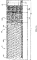
- FIG. 1A illustrates a catheter 10 having a braid 100.
- the catheter 10 can include an elongated tubular body 120.
- the tubular body 120 can be made of various medical grade polymers, such as PTFE, polyether block amide (Pebax ® ), or Nylon.
- the catheter 10 can include a braid 100 disposed over the tubular body 120.
- the braid 100 can extend a length L.
- the braid 100 can extend a length L that is substantially the same as the length of the tubular body 120. Alternatively, the braid 100 can extend over a portion of the tubular body 120.
- the braid 100 can be a single continuous braid extending over the tubular body 120 and can have a proximal portion 102, a transitional portion 104, and a distal portion 106.
- the proximal portion 102 can extend between approximately 45 centimeters to approximately 55 centimeters
- the transitional portion 104 can extend between approximately 5 centimeters and approximately 15
- the distal portion 106 can extend between approximately 25 centimeters and approximately 35 centimeters.
- the braid 100 can be made of a plurality of wire segments 108.
- the wire segments 108 can be made of a variety of metallic materials.
- the wire segments 108 can be made from stainless steel, cobalt chromium, molybdenum and niobium alloy, or any other hard metal alloy.
- the braid 100 can have varying picks per inch along its length L.
- the proximal portion 102 of the braid 100 can have a low picks per inch as compared to the transitional portion 104 and the distal portion 106, thereby aiding in axial rigidity.
- the proximal portion 102 can have a picks per inch of between approximately 20 and approximately 50.
- the picks per inch of the braid 100 can increase within the transitional portion 104 and the distal portion 106.
- the transitional portion 104 can have a picks per inch of between approximately 50 and approximately 90.
- the distal portion 106 can have a picks per inch of between approximately 110 and approximately 200, thereby providing a flexible catheter shaft that can effectively navigate through tortuous vasculature.
- each wire segment of the plurality of wire segments 108 can have a first cross-section shape at the proximal portion 102 and a second cross-section shape at the distal portion 106.
- the transitional portion 104 can facilitate gradually transitioning the wire segments 108 from the first cross-section shape to the second cross-section shape.
- the catheter 10 can further include a marker band 110 disposed approximate a tip 122 of the tubular body 120.
- the markerband 110 can be affixed to the tubular body 120 to provide radiopacity, thereby allowing users to precisely locate the catheter 10 within the vasculature of a patient.
- the marker band 110 can be a platinum marker band.
- a polymer jacket 124a can be disposed around the braid 100.
- a first polymer jacket 124a can be disposed around the proximal portion 102 of the braid 100. In some instances, the first polymer jacket 124a can be disposed around the proximal portion 102 and at least a portion of the transitional portion 104. The first polymer jacket 124a can have between approximately 60 to approximately 80 durometers.
- a second polymer jacket 124b can be disposed around at least a portion of the transitional portion 104 and the distal portion 106 of the braid 100. In some instances, the second polymer jacket 124b can extend to the tubular body tip 122 and thus can cover the marker band 110. The second polymer jacket 124b can have between approximately 40 to approximately 80 durometers.
- FIG. 1B illustrates a wire segment 108 of the braid 100 illustrated in FIG. 1A .
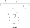
- FIGs. 1C and 1D illustrate cross-sections of respective wire segment portions 108a, 108c of the wire segment 108 as indicated in FIG. 1B .
- the wire segments 108 of the braid 100 can have varying cross-sections as the braid 100 extends from its proximal portion 102 to its distal portion 106.
- the proximal portion 102 can include the wire segment portion 108a having a substantially rectangular cross-section.
- the wire segment portion 108a within the proximal portion 102 of the braid 100 can be designed to maximize the width 112.
- the width 112 of the wire segment portion 108a at the proximal portion 102 can be approximately 0.25 millimeters (0.01 inches).
- the resulting braid 100 can substantially resemble a metal hypotube.
- the wire segment portion 108a can further be designed to have a height 110 of approximately 0.01 millimeters (0.0004 inches). Accordingly, the proximal portion 102 of the braid 100 can provide sufficient column strength and axial rigidity.
- the distal portion 106 can include the wire segment portion 108c having a substantially circular cross-section.
- the wire segment portion 108c can have a diameter 114 of approximately 0.06 millimeters (0.0025 inches).
- the diameter 114 can be maintained relatively small, allowing for the overall inner diameter of the catheter 10 to be larger compared to several commercially available catheters.
- the circular cross-section of the wire segment portion 108c can provide increased flexibility as compared to the wire segment portions 108a within the proximal portion 102. Having a flexible catheter tip can facilitate navigating the distal end of the catheter 10 through tortuous vasculature.
- the transitional portion 104 of the braid 100 can include wire segment portion 108b having a varying cross-section shape.
- the wire segment portion 108b can have a substantially rectangular cross-section shape proximate the proximal portion 102 and gradually transition to a substantially circular cross-section shape proximate the distal portion 106.
- the smooth transition can facilitate the transmission of force as the catheter 10 is pushed distally through vasculature.
- the proximal shaft of the catheter 10 can have the desired stiffness and column strength for sufficient navigation, thereby reducing the potential for damage during navigation, while the distal shaft of the catheter 10 can have the desired flexibility and trackability.
- FIG. 2A illustrates the catheter 10 including an alternative example braid 200, 300, 400.
- FIGs. 2A through 2D illustrate the example braid 200 including a plurality of wire segments 208.
- FIGs. 2A and 3A through 3C illustrate the example braid 300 including a plurality of wire segments 308.
- FIGs. 2A and 4A and 4B illustrate the example braid 400 including a plurality of wire segments 408. Accordingly, the example braid 200, 300, 400 can be similarly disposed over the tubular body 120 of the catheter 10, however, some of the characteristics of the plurality of wire segments 208, 308, 408 can vary depending on the example braid 200, 300, 400.
- the catheter 10 can include the tubular body 120.
- the braid 200, 300, 400 can extend a length L over the catheter 10. In some instances, the braid 200, 300, 400 can extend over a portion of the catheter 10. Alternatively, the braid 200, 300, 400 can extend over the entire length of the catheter 10.
- the braid 200, 300, 400 can have a proximal portion 202, 302, 402 having a proximal end 202a, 302a, 402a and a distal portion 206, 306, 406 having a distal end 206a, 306a, 406a.
- the braid 200 can further include a transitional portion 204 that can extend over at least a portion of the proximal portion 202 and at least a portion of the distal portion 206.
- the braid 200, 300, 400 can be made of a plurality of wire segments 208, 308, 408 and can have varying picks per inch as the braid 200, 300, 400 extends the length L along the catheter 10.
- the proximal portion 202, 302, 402 of the braid 200, 300, 400 can have a picks per inch of between approximately 20 to approximately 45.
- the distal portion 206, 306, 406 of the braid 200, 300, 400 can have a picks per inch of between approximately 120 to approximately 200.
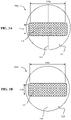
- FIGs. 2B through 2D illustrate cross-section views of the respective wire segment portions 208a, 208b, 208c of each wire segment 208 of braid 100b.
- the wire segments 208 can be drawn filled tubes ("DFT") with each wire segment 208 having an outer shell 210 and an inner core 212.
- the outer shell 210 can have a material composition and the inner core 212 can have a material composition that is different from the material composition of the outer core 212 over at least a portion of the wire segment 208.
- the wire segment 208 can bend and flex equally in all radial directions.
- the wire segment can bend or flex in preferable directions as dictated by the non-circular shape of the inner core 212 while maintaining a circular outer profile.
- the first metal composition of the outer shell 210 can remain the same as the braid 100b and extends along the length L of the braid 200.
- the second composition of the inner core 212 can vary as the braid 200 extends from the proximal portion 202 to the distal portion 206, such that the second composition can be different than the first composition along at least a portion of the length L of the braid 200.
- the inner core 212 can have a varying cross-section shape as the braid 100b extends over the tubular body 120. By gradually varying the cross-section shape of the inner core 212 and/or varying the material composition of the inner core 212, the catheter 10 can have a relatively stiff proximal shaft and a relatively flexible distal shaft, thereby providing effective navigation through vasculature.
- FIG. 2B illustrates a cross-section view of the first wire segment portion 208a of the wire segment 208.
- the first wire segment portion 208a can be disposed over the proximal portion 202 of the braid 200.
- the first wire segment portion 208a can include the outer shell 210 and the inner core 212.
- the outer shell 210 can have a substantially circular cross-section.
- the outer shell 210 can have a diameter 214 of approximately 0.06 millimeters (0.0025 inches).
- the outer shell 210 includes stainless steel and the composition of the inner core 212 includes a relatively stiff metal and/or combination of metals compared to the outer shell 210 over at the proximal portion 202 of the wire segment 208.
- the inner core 212 of the first wire segment portion 208a can be made of cobalt chromium, martensitic steel, or chromium-steel.
- the outer shell 210 can be stiffer than the inner core 212 in the proximal portion 202.
- Overall stiffness of each segment portion 208a, 208b, 208c of the wire segment 208 can be determined based on relative cross-sectional area of the outer shell 210 compared to the inner core 212, where the material that encompasses the greatest cross-sectional area has the greatest effect on the overall stiffness of the wire segment.
- the shape and material properties of the inner core 212 can more significantly determine overall material properties of the wire segment 208 than the outer shell 210.
- Relative stiffness of the outer shell 210 and the inner core 212 can be based on the Young's Modulus and/or ultimate tensile strength (“UTS") value of the metal compositions of the outer shell 210 and the inner core 212.
- the inner core 212 can have a substantially rectangular cross-section shape.
- the inner core 212 have a length 218 that is similar to the diameter 214 of the outer shell 210 and a width 216.
- the inner core 212 can have a length 218 of approximately 0.05 millimeters (0.0018 inches) and a width 216 of approximately 0.01 millimeters (0.0003 inches).
- the ratio between the length 218 of the inner core to the width 216 of the inner core can be approximately 6 to 1.
- a circular outer shell 210 with an inner core 212 having a substantially rectangular cross-section shape and a relatively stiff metal composition e.g., having a Young's Modulus and/or UTS that is substantially similar to or greater than that of the outer shell 210) can allow the wire segment portion 208a to be round wire but have similar characteristics and functionality as a flat wire.
- the first wire segment portion 208a can provide increased axial rigidity and stiffness at the proximal end of the catheter 10 as compared to a catheter having entirely round wires with no inner core 212.
- FIG. 2C illustrates a cross-section view of the second wire segment portion 208b of the wire segment 208.
- the second wire segment portion 208b can be disposed over the transitional portion 204 of the braid 200.
- the composition of the inner core 212 in the second wire segment portion 208b can be made a second metal and/or combination of metals that is less stiff (e.g., having a lower Young's Modulus and/or UTS value) than the first metal(s) of the inner core 212 of the proximal portion, thereby increasing flexibility as the braid 100b extends along the length L of the catheter 10.
- the outer shell 210 can have a substantially circular cross-section with the same diameter 214 as the second wire segment portion 208a.
- the inner core 212 can have a varying cross-section shape.
- the inner core 212 can have a substantially rectangular cross-section shape approximate to the proximal portion 202 and have a substantially circular cross-section shape approximate to the distal portion 206.
- the inner core 212 can have a substantially elongated, oval or stadium shape at approximately the middle of the transitional portion 204.
- the length 222 of the edge of the inner core 212 be approximately 0.02 millimeters (0.00065 inches).
- the width 224 of the inner core 212 can be approximately 0.03 millimeters (0.0012 inches).
- FIG. 2D illustrates a cross-section view of the third wire segment portion 208c of the wire segment 208.
- the third wire segment portion 208c can be disposed over the at the distal portion 206 of the braid 100b.
- the outer shell 210 can maintain its substantially circular cross-section with the same diameter 214 as the first wire segment portion 208a and the second wire segment portion 208b.
- the composition of the inner core 212 can be a third metal and/or combination of metals that is less stiff (e.g., having a lower Young's Modulus and/or UTS value) than the second metal(s) and the first metal(s) of the inner core 212 at the transitional portion 204 and the proximal portion 202, respectively.
- the inner core 212 can be a cavity or void, thereby providing enhanced flexibility of the catheter shaft at the distal portion 206.
- the inner core 212 can have a substantially circular cross-section.
- the diameter of the inner core 212 can be approximately 0.04 millimeters (0.0015 inches).
- Varying the cross-section shape of the inner core 212 along the proximal portion 202, the transitional portion 204, and the distal portion 206 of the braid 200 can provide the catheter 10 with sufficient axial stiffness at the proximal end of the catheter 10 and sufficient flexibility at the distal end of the catheter 10, thereby column strength and axial rigidity is not sacrificed in order to provide a flexible catheter tip that can navigate tortuous vasculature.
- the gradual transition from the rectangular cross-section shape to the circular cross-section shape of the inner core 212 can further reduce the potential for kinking during navigation.
- FIGs. 3A and 3B illustrate alternative example wire segments 308 of the braid 300.
- FIG. 3A illustrates a first wire segment portion 308a of the wire segment 308.
- the first wire segment portion 308a can be disposed over the proximal portion 302 of the braid 300.
- FIG. 3B illustrates a second wire segment portion 308b of the wire segment 308.
- the second wire segment portion 308b can be disposed over the distal portion 206 of the braid 300.
- the wire segment 308 can have the outer shell 310 and the inner core 312. As in FIGs. 2B through 2D , the outer shell 310 can have that has a substantially circular cross-section shape.
- the inner core 312 can be have a substantially rectangular cross-section shape at both the proximal portion 202 and the distal portion 206. Accordingly, the inner core 312 can have a substantially rectangular cross-section shape along the entire length L of the braid 300.
- the length 318a of the inner core 312 at the proximal portion 302 can be substantially equal to the length 318b of the inner core 312 at the distal portion 306.
- the length 318a, 318b can be approximately 0.04 millimeters (0.0018 inches).
- the width 316a of the inner core 312 at the proximal portion 202 can be substantially equal to the width 316b of the inner core 212 at the distal portion 206.
- the width 316a, 316b can be approximately 0.01 millimeters (0.0003 inches).
- the ratio between the length 318 of the inner core to the width 316 of the inner core 312 can be approximately 6 to 1.
- the inner core 312 of FIGs. 3A and 3B has a constant rectangular cross-section shape
- the inner core 312 of the first wire segment portion 308a at the proximal portion 302 of the braid 300 can include one metal or metals while the inner core 312 of the second wire segment portion 308b at the distal portion 306 of the braid 300 can include a different metal or metals.
- the inner core 312 of the first wire segment portion 308a can include a metal or a combination of metals that is stiffer and can provide increased column strength to the catheter 10 as compared to the inner core 312 of the second wire segment portion 308b.
- the second wire segment portion 308b can include a metal or a combination of metals having a Young's Modulus and/or ultimate tensile strength ("UTS") that is less than the metal or combination of metals of the first wire segment portion 308a.
- the second wire segment portion 308b can include nitinol, titanium, austenitic steels, and/or stainless steel
- the first wire segment portion 308a can include martensitic steels, stainless steel, tantalum, tungsten, molybdenum, rhenium, and/or cobalt chromium alloys.
- the braid 300 can provide increasing flexibility to the distal end of the catheter 10 by varying the metal composition of the inner core 312 as the braid 300 extends along the length of the catheter 10.
- FIGs. 4A through 4C illustrate an additional example of wire segments 408 of braid 400.
- the outer shell 410 is divided into an upper semi-cylinder 420and a lower semi-cylinder 422 with respect to a longitudinal axis LA.
- the upper semi-cylinder 420 can include a first metal and/or first combination of metals and the lower semi-cylinder 422 can include a second metal and/or a second combination of metals.
- the second metal and/or second combination of metals in the lower semi-cylinder 422 can have a greater density than the first metal and/or first combination of metals.
- the inner core 412 can be made of a metal(s) having a different density than both the first metal and/or first combination of metals of the upper semi-cylinder 420 and the second metal and/or second combination of metals of the lower semi-cylinder 422.
- the inner core 412 can be made of a metal(s) that has a greater density than the first metal and/or combination of metals and a smaller density than the second metal and/or combination of metals.
- one or more air channels 414 can be created within the upper semi-cylinder 420. Any number of air channels 414 can be created within the upper semi-cylinder 420.
- the air channels 414 can have any shape.
- the upper semi-cylinder 420 can include three air channels 414 having a circular cross-section.
- the air channels 414 can have a diameter 416 of approximately 0.01 millimeters (0.00045 inches). As illustrated in FIG.
- the upper cylinder 420 can include one air channel 414 having a substantially semi-circle cross-section shape such that the air channel 414 can resemble the shape and/or size of the upper semi-cylinder 420.
- the semi-circular air channel 414 can have a diameter 418 of approximately 0.05 millimeters (0.002 inches).
- the difference in densities between the upper semi-cylinder 420 and the lower semi-cylinder 422 can be further distinguished, thereby additionally biasing the wire segment 408 to be positioned such that the lower semi-cylinder 422 is directed towards the inner lumen of the braid 400 to prevent twisting during braiding.
- FIG. 5A is an illustration of the catheter 10 including a first braid 506 and a second braid 508.
- the catheter 10 can include a tubular body 120.
- the tubular body 120 can have a proximal portion 502 and a distal portion 504.
- the first braid 506 can be disposed over the proximal portion 502 of the tubular body 120 and the second braid 508 can be disposed over the distal portion 504 of the tubular body 120.
- the first braid 506 can be made of a first plurality of wire segments 514 and the second braid 508 can be made of a second plurality of wire segments 516.
- the first braid 506 can be constructed to have a smaller picks per inch than the second braid 508.
- the first braid 506 can have a picks per inch of between approximately 20 and approximately 45 and the second braid 508 can have a picks per inch of between approximately 120 and approximately 200.
- the first braid 506 and the second braid 508 can be disposed over the tubular body 120 such that any gap between the first braid 506 and the second braid 508 is minimal, as a gap can cause potential kink points.
- the first braid 506 and the second braid 508 can abut one another, such that the first braid 506 transitions into the second braid 508, and accordingly the first plurality of wire segments 514 transition into the second plurality of wire segments 516.
- the first braid 506 and the second braid 508 can overlap.
- the distal end of the first braid 506 can overlap with the proximal end of the second braid 508.
- Such overlap of the first braid 506 and the second braid 508 can eliminate a gap between the two braids 506, 508, and thus, decrease the chance for kink points and unsuccessful delivery of the catheter 10 to the proper location.
- FIG. 5B illustrates a cross-section view of a wire segment 514 of the first braid 506.
- the wire segment 514 can include a first outer shell 510a having the substantially circular cross-section shape.
- the wire segment 514 can have a first inner core 512a that can have a substantially rectangular cross-section shape.
- the first inner core 512a of the wire segment 514 can have a composition including a first metal.
- the first metal can be a relatively stiff metal (e.g., cobalt chromium, martensitic steel, chromium steel).
- FIG. 5C illustrates a cross-section view of a wire segment 516 of the second braid 508.
- the wire segment 516 can also have a second outer shell 510b having the substantially circular cross-section shape.
- the wire segment 516 can have a second inner core 512b having a substantially circular cross-section shape.
- the second inner core 512b of the wire segment 516 can have a composition including a second metal that is less stiff than the first metal of the inner core 512b of the wire segment 514.
- the second inner core 512b of the wire segment 516 can be an air cavity 520, such that the second inner core 512b does not contain any metal.
- the catheter 10 can have a relatively flexible distal shaft and a relatively stiff proximal shaft, thereby the catheter 10 does not have to sacrifice column strength in order to have the necessary flexibility to navigate tortuous vasculature.
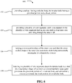
- FIG. 6 illustrates a flow chart outlining an example method 600 of manufacturing a catheter braid 200.
- a catheter 10 having a tubular body 120 is provided.
- the tubular body can have a proximal portion and a distal portion.
- a plurality of wire segments 208 can be provided.
- Each wire segment of the plurality of wire segments 208 can have an outer shell 210 and an inner core 212 extending through the outer shell 210.
- a cross-section shape of the inner core 212 can be varied such that the cross-section shape of the inner core 212 transitions from being substantially rectangular to substantially circular.
- the plurality of wire segments 208 can be braided about the tubular body 120 such that the cross-section shape of the inner core 212 is substantially rectangular proximate the proximal portion of the tubular body 120 and substantially circular proximate the distal portion of the tubular body 120.
- FIG. 7 illustrates a flow chart outlining an additional and/or alternative example method 700 of manufacturing a catheter braid 200, 300.
- a catheter 10 having a tubular body 120 is provided.
- the tubular body can have a proximal portion and a distal portion.
- a plurality of wire segments 208, 308 can be provided.
- Each wire segment of the plurality of wire segments 208, 308, 408 can have an outer shell 210, 310 and an inner core 212, 312, extending through the outer shell 210, 310.
- a material composition of the inner core 212, 312 can be varied such that the material composition of the inner core 212, 312 transitions from being relatively stiff to relatively flexible.
- the material composition of the inner core 212, 312 can include varying metals create a wire segment 208, 308 having varying stiffness.
- the plurality of wire segments 208, 308 can be braided about the tubular body 120 such that the cross-section shape of the inner core 212, 312 is relatively stiff proximate the proximal portion of the tubular body 120 and relatively flexible proximate the distal portion of the tubular body 120.
- the invention contemplates many variations and modifications of the inventive delivery and release system for a vascular occlusion device, including numerous configurations, numerous stiffness properties and methods for delivering the same. Also, there are many possible variations in the materials and configurations of the release mechanism. These modifications would be apparent to those having ordinary skill in the art to which this invention relates and are intended to be within the scope of the claims which follow.
Landscapes
- Health & Medical Sciences (AREA)
- Life Sciences & Earth Sciences (AREA)
- Animal Behavior & Ethology (AREA)
- Veterinary Medicine (AREA)
- Public Health (AREA)
- General Health & Medical Sciences (AREA)
- Engineering & Computer Science (AREA)
- Heart & Thoracic Surgery (AREA)
- Hematology (AREA)
- Biomedical Technology (AREA)
- Anesthesiology (AREA)
- Pulmonology (AREA)
- Biophysics (AREA)
- Chemical & Material Sciences (AREA)
- Inorganic Chemistry (AREA)
- Epidemiology (AREA)
- Media Introduction/Drainage Providing Device (AREA)
Abstract
Description
- This application claims the benefit of
U.S. Patent Application No. 63/110,613, filed on 6 November 2020 - This invention generally relates to devices and methods for accessing blood vessels during intravascular medical treatments. More specifically, the present disclosure relates to a catheter having improved flexibility while maintaining axial stiffness.
- Catheters serve a broad range of functions in intravascular medical treatments. Catheters are typically a thin tube manufactured from medical grade materials that can be inserted into a body and can be used to deliver drugs or other devices, perform surgical procedures, remove blockages from vessels, and a variety of other purposes. By modifying the material or adjusting the way a catheter is manufactured, it is possible to tailor different sections of the catheter for particular applications.
- Several designs and methods have been proposed for navigating a catheter to a target site. In one method, the catheter fits over, and is slid along, a guidewire which is used to gain access to a target site. A thin guidewire, however, almost always has more reach and distal flexibility than the catheter tube. Newer designs have been proposed which utilize various methods to alter the stiffness between the proximal and distal portions of the catheter, such as sets of polymer tubing, often with braids or windings involving wires or bands of other materials for reinforcement. Current designs can include softer, more flexible distal portions of the catheter while increasing the stiffness towards the proximal portion of the catheter. In such designs, a smooth transition from the softer, more flexible distal portion to the stiffer proximal portion can facilitate successful usage for vascular applications. However, some existing designs lack the strength to be useful for some medical procedures or contain abrupt stiffness or geometric changes which can hinder trackability, introduce significant stress concentrations, and potentially increase the likelihood of device kinking or buckling. As a result, some designs often have pushability, trackability, or kink levels which are unacceptable for wide adoption among physicians.
- Thus, there is a need for systems, devices, and methods that can provide a smooth transition from a relatively stiff proximal portion to a relatively flexible distal portion of a catheter while maintaining axial stiffness.
- Generally, it is an object of the present invention to provide a catheter braid including wire segments with varying cross-section shapes to provide a relatively soft, flexible catheter shaft at a distal portion of the braid and relatively stiff catheter shaft at the proximal portion of the braid. In an embodiment, the wire segments at the proximal portion can have a substantially rectangular cross-section shape, while wire segments at the distal portion can have a substantially circular cross-section shape. The cross-section shape of wire segment can gradually transition from the rectangular cross-section shape to the circular cross-section shape to provide a smooth transition, thereby minimizing the potential of kinking. In an additional embodiment, the wire segments can have an outer core and an inner core. The inner core at the proximal portion of the braid can have a substantially rectangular cross-section shape, while the inner core at the distal portion of the braid can have a substantially circular cross-section shape. The cross-section shape of the inner core can gradually transition from rectangular to circular to provide a smooth transition. The composition of the outer shell can be different than the composition of the inner core, and the composition of the inner core can vary as the wire segments extend from the proximal portion to the distal portion. By varying the cross-section shape and/or composition of the inner core, the catheter can smoothly transition from a rigid and stiff shaft at the proximal portion to a soft, flexible shaft at the distal portion.
- An example catheter braid can include a proximal portion with a proximal end, a distal portion with a distal end, and a length extending between the proximal and distal ends. The catheter braid can include a plurality of wire segments, each wire segment including an outer shell and an inner core. The outer shell can have a first material composition. The inner core can extend through the outer shell and can have a second material composition that is different than the first material composition over at least a portion of the length of the catheter braid. The inner core can have a first cross-section shape approximate the proximal end and a second cross-section shape approximate the distal end. The first cross-section shape can transition to the second cross-section shape along the length of the catheter braid.
- The proximal portion of the catheter braid can have a first picks per inch and the distal portion of the catheter braid can have a second picks per inch. The first picks per inch can be less than the second picks per inch.
- The first picks per inch can be between approximately 20 and approximately 45. The second picks per inch can be between approximately 120 and approximately 200.
- The first cross-section shape can be substantially rectangular, and the second cross-section shape can be substantially circular.
- The catheter braid can further include a transitional portion extending over at least a portion of the proximal portion and over at least a portion of the distal portion. The transitional portion can have a variable cross-section shape that can be substantially rectangular approximate the proximal portion and can gradually transition to be substantially circular approximate the distal portion.
- The second material composition can include a first metal at the proximal portion, a second metal at the transitional portion, and a third metal at the distal portion. The first metal can have a greater stiffness than the second metal and the third metal. The second metal can have a greater stiffness than the third metal.
- The inner core can be a cavity at the distal end of the distal portion.
- The first-cross-section shape can be substantially rectangular, and the second cross-section shape can be substantially rectangular.
- The inner core can include a first metal at the proximal portion and a second metal at the distal portion. The first metal can have a greater stiffness than the second metal.
- The outer shell can include an upper semi-cylinder with respect to a longitudinal axis and a lower semi-cylinder with respect to the longitudinal axis.
- The inner core can include a first metal, the upper semi-cylinder can include a second metal, and the lower semi-cylinder can include a third metal. The third metal can have a greater density than the first metal and the second metal and the first metal can have a greater density than the second metal.
- The upper semi-cylinder can include one or more air channels.
- Another example catheter can include a tubular body, a first braid, and a second braid. The tubular body can include a proximal portion and a distal portion. The first braid can be disposed over the proximal portion. The first braid can include a first plurality of wire segments. Each wire segment can include a first outer shell and a first inner core with a substantially rectangular cross-section shape. The second braid can be disposed over the distal portion. The second braid can include a second plurality of wire segments. Each wire segment can have a second outer shell and a second inner core with a substantially circular cross-section shape.
- The first braid can have a first picks per inch and the second braid can have a second picks per inch. The second picks per inch can be greater than the first picks per inch.
- The inner core of each wire segment of the second plurality of wire segments can be a cavity approximate the distal end of the distal portion.
- Another example catheter braid disposed along a length of a catheter can include a proximal portion and a distal portion. The proximal portion can include wire segments having a first cross-section shape that is substantially rectangular. The distal portion can include wire segments having a second cross-section shape that is substantially circular.
- The proximal portion can have a smaller picks per inch that the distal portion.
- The catheter braid can further include a transitional portion disposed between the proximal portion and the distal portion. The transitional portion can have a greater picks per inch than the proximal portion and a smaller picks per inch than the distal portion.
- The transitional portion can extend a length of between approximately 5 and approximately 15 centimeters and can have a variable cross-section. The variable cross-section can be substantially rectangular proximate the proximal portion and substantially circular proximate the distal portion.
- The proximal portion can have a picks per inch of between approximately 20 and approximately 50, the transitional portion can have a picks per inch of between approximately 50 and approximately 90, and the distal portion can have a picks per inch of between approximately 110 and approximately 200.
- Features of above example catheters are combinable according to teachings herein and/or in ways apparent to a person skilled in the pertinent art.
- The above and further aspects of this invention are further discussed with reference to the following description in conjunction with the accompanying drawings, in which like numerals indicate like structural elements and features in various figures. The drawings are not necessarily to scale, emphasis instead being placed upon illustrating principles of the invention. The figures depict one or more implementations of the inventive devices, by way of example only, not by way of limitation.
-
FIG. 1A is an illustration of a catheter including an example braid, according to aspects of the present invention; -
FIG. 1B is an illustration of an example wire segment of the braid ofFIG. 1A , according to aspects of the present invention; -
FIG. 1C is a cross-section view of the wire segment ofFIG. 1B at a proximal portion of the example braid, according to aspects of the present invention; -
FIG. 1D is a cross-section view of the wire segment ofFIG. 1B at a distal portion of the example braid, according to aspects of the present invention; -
FIG. 2A is an illustration of a catheter including an alternative example braid, according to aspects of the present invention; -
FIG. 2B is a cross-section view of a wire segment at a proximal portion of the example braid ofFIG. 2A , according to aspects of the present invention; -
FIG. 2C is a cross-section view of a wire segment at a transitional portion of the example braid inFIG. 2A , according to aspects of the present invention; -
FIG. 2D is a cross-section view of a wire segment at a distal portion of the example braid inFIG. 2A , according to aspects of the present invention; -
FIGs. 3A-3B are cross-section views of an alternative example wire segment of the braid inFIG. 2A , according to aspects of the present invention; -
FIGs. 4A-4C are cross-section views of an alternative example wire segment of the braid inFIG. 2A , according to aspects of the present invention; -
FIG. 5A is an illustration of a catheter including a first braid and a second braid, according to aspects of the present invention; -
FIG. 5B is a cross-section view of a wire segment of the first braid inFIG. 5A , according to aspects of the present invention; -
FIGs. 5C-5D are cross-section views of a wire segment of the second braid inFIG. 5A , according to aspects of the present invention; -
FIG. 6 is a flow diagram outlining an example method of manufacturing an example braid; and -
FIG. 7 is a flow diagram outlining an additional or alternative method of manufacturing an example braid. - The disclosed technology can include a catheter braid including wire segments with varying cross-section shapes over the length of the braid to provide a relatively soft, flexible shaft at the distal portion, relatively stiff shaft at the proximal portion, and a graduated transition between the flexible shaft and stiff shaft. In an embodiment, the wire segments at the proximal portion of the braid can have a substantially rectangular cross-section shape, thereby providing a rigid proximal shaft and maximizing column strength. The cross-section shape of wire segment can gradually transition from rectangular to circular to provide increased radial flexibility at the distal portion. By gradually transitioning from one cross-section shape to a different cross-section shape the potential for kinks can be reduced. In an additional embodiment, the wire segments can have an outer core and an inner core. The inner core at the proximal section of the braid can have a substantially rectangular cross-section shape, while the inner core at the distal portion of the braid can have a substantially circular cross-section shape. The cross-section shape of the inner core can gradually transition from rectangular to circular to provide a smooth transition. The composition of the outer shell can be different than the composition of the inner core, and the composition of the inner core can vary as the wire segment extends from the proximal portion to the distal portion. By varying the cross-section shape and/or composition of the inner core, the catheter can smoothly transition from a rigid and stiff shaft at the proximal portion to a soft, flexible shaft at the distal portion without sacrificing proximal shaft push efficiency.
- Although example embodiments of the disclosed technology are explained in detail herein, it is to be understood that other embodiments are contemplated. Accordingly, it is not intended that the disclosed technology be limited in its scope to the details of construction and arrangement of components set forth in the following description or illustrated in the drawings. The disclosed technology is capable of other embodiments and of being practiced or carried out in various ways.
- It must also be noted that, as used in the specification and the appended claims, the singular forms "a," "an" and "the" include plural referents unless the context clearly dictates otherwise. By "comprising" or "containing" or "including" it is meant that at least the named compound, element, particle, or method step is present in the composition or article or method, but does not exclude the presence of other compounds, materials, particles, method steps, even if the other such compounds, material, particles, method steps have the same function as what is named.
- In describing example embodiments, terminology will be resorted to for the sake of clarity. It is intended that each term contemplates its broadest meaning as understood by those skilled in the art and includes all technical equivalents that operate in a similar manner to accomplish a similar purpose. It is also to be understood that the mention of one or more steps of a method does not preclude the presence of additional method steps or intervening method steps between those steps expressly identified. Steps of a method may be performed in a different order than those described herein without departing from the scope of the disclosed technology. Similarly, it is also to be understood that the mention of one or more components in a device or system does not preclude the presence of additional components or intervening components between those components expressly identified.
- As discussed herein, vasculature can be that of any "subject" or "patient" including of any human or animal. It should be appreciated that an animal may be a variety of any applicable type, including, but not limited thereto, mammal, veterinarian animal, livestock animal or pet type animal, etc. As an example, the animal may be a laboratory animal specifically selected to have certain characteristics similar to a human (e.g., rat, dog, pig, monkey, or the like). It should be appreciated that the subject may be any applicable human patient, for example.
- As discussed herein, the terms "about" or "approximately" for any numerical values or ranges indicate a suitable dimensional tolerance that allows the part or collection of components to function for its intended purpose as described herein. More specifically, "about" or "approximately" may refer to the range of values ±20% of the recited value, e.g. "about 90%" may refer to the range of values from 71% to 99%.
- As used herein, the term "substantially" in describing a geometrical property indicates a suitable dimensional tolerance that allows the part of collection of components to function for its intended purpose and the geometric property, despite deviations from a strict shape, is appropriately described as being close to the described strict shape. For instance, a "substantially" rectangular shape may deviate from a strictly rectangular shape, e.g. rounded corners, sides that are not precisely parallel, and/or corners that are not precisely 90°, where the "substantially" rectangular shape achieves similar functionality to that of a strictly rectangular shape. A "substantially" rectangular shape may close enough to a strictly rectangular shape that "rectangular" is a reasonably appropriate descriptor by the plain and ordinary meaning of the word "rectangular". A rectangle with semicircles at each short side, sometimes referred to as "stadium" shape, may be considered "substantially" rectangular as "stadium" is a less common shape descriptor compared to "rectangular" and when a feature having a "stadium" shape retains its functionality when the "stadium" shape is replaced by a "rectangular" shape.
- The figures illustrate a generally hollow or tubular structure according to the present invention. When used herein, the terms "tubular" and "tube" are to be construed broadly and are not limited to a structure that is a right cylinder or strictly circumferential in cross-section or of a uniform cross-section throughout its length. For example, the tubular structure or system is generally illustrated as a substantially right cylindrical structure. However, the tubular system may have a tapered or curved outer surface without departing from the scope of the present invention.
- Referring now to the figures,
FIG. 1A illustrates acatheter 10 having abraid 100. Thecatheter 10 can include an elongatedtubular body 120. Thetubular body 120 can be made of various medical grade polymers, such as PTFE, polyether block amide (Pebax®), or Nylon. Thecatheter 10 can include abraid 100 disposed over thetubular body 120. Thebraid 100 can extend a length L. Thebraid 100 can extend a length L that is substantially the same as the length of thetubular body 120. Alternatively, thebraid 100 can extend over a portion of thetubular body 120. Thebraid 100 can be a single continuous braid extending over thetubular body 120 and can have aproximal portion 102, atransitional portion 104, and adistal portion 106. By way of example, theproximal portion 102 can extend between approximately 45 centimeters to approximately 55 centimeters, thetransitional portion 104 can extend between approximately 5 centimeters and approximately 15, and thedistal portion 106 can extend between approximately 25 centimeters and approximately 35 centimeters. - The
braid 100 can be made of a plurality ofwire segments 108. Thewire segments 108 can be made of a variety of metallic materials. By way of example, thewire segments 108 can be made from stainless steel, cobalt chromium, molybdenum and niobium alloy, or any other hard metal alloy. Thebraid 100 can have varying picks per inch along its length L. Theproximal portion 102 of thebraid 100 can have a low picks per inch as compared to thetransitional portion 104 and thedistal portion 106, thereby aiding in axial rigidity. By way of example, theproximal portion 102 can have a picks per inch of between approximately 20 and approximately 50. In order to provide increased radial flexibility approximate the distal end of thecatheter 10, the picks per inch of thebraid 100 can increase within thetransitional portion 104 and thedistal portion 106. Thetransitional portion 104 can have a picks per inch of between approximately 50 and approximately 90. Thedistal portion 106 can have a picks per inch of between approximately 110 and approximately 200, thereby providing a flexible catheter shaft that can effectively navigate through tortuous vasculature. - As further discussed herein, each wire segment of the plurality of
wire segments 108 can have a first cross-section shape at theproximal portion 102 and a second cross-section shape at thedistal portion 106. Thetransitional portion 104 can facilitate gradually transitioning thewire segments 108 from the first cross-section shape to the second cross-section shape. - The
catheter 10 can further include amarker band 110 disposed approximate atip 122 of thetubular body 120. Themarkerband 110 can be affixed to thetubular body 120 to provide radiopacity, thereby allowing users to precisely locate thecatheter 10 within the vasculature of a patient. By way of example, themarker band 110 can be a platinum marker band. - A polymer jacket 124a can be disposed around the
braid 100. A first polymer jacket 124a can be disposed around theproximal portion 102 of thebraid 100. In some instances, the first polymer jacket 124a can be disposed around theproximal portion 102 and at least a portion of thetransitional portion 104. The first polymer jacket 124a can have between approximately 60 to approximately 80 durometers. Asecond polymer jacket 124b can be disposed around at least a portion of thetransitional portion 104 and thedistal portion 106 of thebraid 100. In some instances, thesecond polymer jacket 124b can extend to thetubular body tip 122 and thus can cover themarker band 110. Thesecond polymer jacket 124b can have between approximately 40 to approximately 80 durometers. -
FIG. 1B illustrates awire segment 108 of thebraid 100 illustrated inFIG. 1A .FIGs. 1C and 1D illustrate cross-sections of respectivewire segment portions wire segment 108 as indicated inFIG. 1B . Referring collectively toFIGs. 1A through 1D , thewire segments 108 of thebraid 100 can have varying cross-sections as thebraid 100 extends from itsproximal portion 102 to itsdistal portion 106. As illustrated inFIG. 1B and1C , theproximal portion 102 can include thewire segment portion 108a having a substantially rectangular cross-section. Thewire segment portion 108a within theproximal portion 102 of thebraid 100 can be designed to maximize thewidth 112. By way of example, thewidth 112 of thewire segment portion 108a at theproximal portion 102 can be approximately 0.25 millimeters (0.01 inches). By maximizing thewidth 112 of thewire segment portion 108a, the resultingbraid 100 can substantially resemble a metal hypotube. Thewire segment portion 108a can further be designed to have aheight 110 of approximately 0.01 millimeters (0.0004 inches). Accordingly, theproximal portion 102 of thebraid 100 can provide sufficient column strength and axial rigidity. - As illustrated in
FIGs. 1B and1D , thedistal portion 106 can include thewire segment portion 108c having a substantially circular cross-section. By way of example, thewire segment portion 108c can have adiameter 114 of approximately 0.06 millimeters (0.0025 inches). Further, when thewire segment portion 108c of thedistal portion 106 are made of alloys, including stainless steel and chromium alloys, cobalt chromium alloys, and molybdenum and niobium alloys, thediameter 114 can be maintained relatively small, allowing for the overall inner diameter of thecatheter 10 to be larger compared to several commercially available catheters. This can allow for an increased lumen for ancillary catheters to be translated through thecatheter 10 as needed or can allow for an increased lumen for aspiration. The circular cross-section of thewire segment portion 108c can provide increased flexibility as compared to thewire segment portions 108a within theproximal portion 102. Having a flexible catheter tip can facilitate navigating the distal end of thecatheter 10 through tortuous vasculature. - As illustrated in
FIG. 1B , thetransitional portion 104 of thebraid 100 can includewire segment portion 108b having a varying cross-section shape. Thewire segment portion 108b can have a substantially rectangular cross-section shape proximate theproximal portion 102 and gradually transition to a substantially circular cross-section shape proximate thedistal portion 106. By gradually transitioning from the rectangular cross-section shape of thewire segment portion 108a within theproximal portion 102 to the circular cross-section shape of thewire segment portion 108c within thedistal portion 106, the potential for one or more kinks can be reduced. The smooth transition can facilitate the transmission of force as thecatheter 10 is pushed distally through vasculature. - By varying the cross-section shape of the braid 100 (by virtue of varying the cross-sectional shape of
wires 108 of the braid 100) as thebraid 100 extends along thetubular body 120 of thecatheter 10, the proximal shaft of thecatheter 10 can have the desired stiffness and column strength for sufficient navigation, thereby reducing the potential for damage during navigation, while the distal shaft of thecatheter 10 can have the desired flexibility and trackability. -
FIG. 2A illustrates thecatheter 10 including an alternative example braid 200, 300, 400.FIGs. 2A through 2D illustrate the example braid 200 including a plurality of wire segments 208.FIGs. 2A and3A through 3C illustrate the example braid 300 including a plurality of wire segments 308.FIGs. 2A and4A and4B illustrate the example braid 400 including a plurality ofwire segments 408. Accordingly, the example braid 200, 300, 400 can be similarly disposed over thetubular body 120 of thecatheter 10, however, some of the characteristics of the plurality ofwire segments 208, 308, 408 can vary depending on the example braid 200, 300, 400. - The
catheter 10 can include thetubular body 120. The braid 200, 300, 400 can extend a length L over thecatheter 10. In some instances, the braid 200, 300, 400 can extend over a portion of thecatheter 10. Alternatively, the braid 200, 300, 400 can extend over the entire length of thecatheter 10. The braid 200, 300, 400 can have a proximal portion 202, 302, 402 having aproximal end transitional portion 204 that can extend over at least a portion of the proximal portion 202 and at least a portion of the distal portion 206. - The braid 200, 300, 400 can be made of a plurality of
wire segments 208, 308, 408 and can have varying picks per inch as the braid 200, 300, 400 extends the length L along thecatheter 10. The proximal portion 202, 302, 402 of the braid 200, 300, 400 can have a picks per inch of between approximately 20 to approximately 45. The distal portion 206, 306, 406 of the braid 200, 300, 400 can have a picks per inch of between approximately 120 to approximately 200. -
FIGs. 2B through 2D illustrate cross-section views of the respectivewire segment portions outer shell 210 and aninner core 212. Theouter shell 210 can have a material composition and theinner core 212 can have a material composition that is different from the material composition of theouter core 212 over at least a portion of the wire segment 208. For aportion 208c of the wire segment 208 having aninner core 212 with a circular cross-section as illustrated inFIG. 2D , the wire segment 208 can bend and flex equally in all radial directions. Forportions inner core 212 as illustrated inFIGs. 2B and 2C , the wire segment can bend or flex in preferable directions as dictated by the non-circular shape of theinner core 212 while maintaining a circular outer profile. The first metal composition of theouter shell 210 can remain the same as the braid 100b and extends along the length L of the braid 200. The second composition of theinner core 212 can vary as the braid 200 extends from the proximal portion 202 to the distal portion 206, such that the second composition can be different than the first composition along at least a portion of the length L of the braid 200. Theinner core 212 can have a varying cross-section shape as the braid 100b extends over thetubular body 120. By gradually varying the cross-section shape of theinner core 212 and/or varying the material composition of theinner core 212, thecatheter 10 can have a relatively stiff proximal shaft and a relatively flexible distal shaft, thereby providing effective navigation through vasculature. -
FIG. 2B illustrates a cross-section view of the firstwire segment portion 208a of the wire segment 208. The firstwire segment portion 208a can be disposed over the proximal portion 202 of the braid 200. The firstwire segment portion 208a can include theouter shell 210 and theinner core 212. Theouter shell 210 can have a substantially circular cross-section. Theouter shell 210 can have adiameter 214 of approximately 0.06 millimeters (0.0025 inches). Preferably, theouter shell 210 includes stainless steel and the composition of theinner core 212 includes a relatively stiff metal and/or combination of metals compared to theouter shell 210 over at the proximal portion 202 of the wire segment 208. By way of example, theinner core 212 of the firstwire segment portion 208a can be made of cobalt chromium, martensitic steel, or chromium-steel. Alternatively, theouter shell 210 can be stiffer than theinner core 212 in the proximal portion 202. Overall stiffness of eachsegment portion outer shell 210 compared to theinner core 212, where the material that encompasses the greatest cross-sectional area has the greatest effect on the overall stiffness of the wire segment. In examples wherein theinner core 212 has a larger cross-sectional area compared in theouter shell 210, therefore, the shape and material properties of theinner core 212 can more significantly determine overall material properties of the wire segment 208 than theouter shell 210. Relative stiffness of theouter shell 210 and theinner core 212 can be based on the Young's Modulus and/or ultimate tensile strength ("UTS") value of the metal compositions of theouter shell 210 and theinner core 212. - The
inner core 212 can have a substantially rectangular cross-section shape. Theinner core 212 have alength 218 that is similar to thediameter 214 of theouter shell 210 and awidth 216. By way of example, theinner core 212 can have alength 218 of approximately 0.05 millimeters (0.0018 inches) and awidth 216 of approximately 0.01 millimeters (0.0003 inches). Similarly, the ratio between thelength 218 of the inner core to thewidth 216 of the inner core can be approximately 6 to 1. By having a circularouter shell 210 with aninner core 212 having a substantially rectangular cross-section shape and a relatively stiff metal composition (e.g., having a Young's Modulus and/or UTS that is substantially similar to or greater than that of the outer shell 210) can allow thewire segment portion 208a to be round wire but have similar characteristics and functionality as a flat wire. Thereby, the firstwire segment portion 208a can provide increased axial rigidity and stiffness at the proximal end of thecatheter 10 as compared to a catheter having entirely round wires with noinner core 212. -
FIG. 2C illustrates a cross-section view of the secondwire segment portion 208b of the wire segment 208. The secondwire segment portion 208b can be disposed over thetransitional portion 204 of the braid 200. The composition of theinner core 212 in the secondwire segment portion 208b can be made a second metal and/or combination of metals that is less stiff (e.g., having a lower Young's Modulus and/or UTS value) than the first metal(s) of theinner core 212 of the proximal portion, thereby increasing flexibility as the braid 100b extends along the length L of thecatheter 10. Theouter shell 210 can have a substantially circular cross-section with thesame diameter 214 as the secondwire segment portion 208a. Theinner core 212 can have a varying cross-section shape. Theinner core 212 can have a substantially rectangular cross-section shape approximate to the proximal portion 202 and have a substantially circular cross-section shape approximate to the distal portion 206. As illustrated inFIG. 2C , theinner core 212 can have a substantially elongated, oval or stadium shape at approximately the middle of thetransitional portion 204. Thelength 222 of the edge of theinner core 212 be approximately 0.02 millimeters (0.00065 inches). Thewidth 224 of theinner core 212 can be approximately 0.03 millimeters (0.0012 inches). By gradually transitioning from the rectangular cross-section shape of thewire segment portions 208a in the proximal portion 202 to the circular cross-section shape of the wire segment portions208c in the distal portion 206, the potential for kinks can be reduced. -
FIG. 2D illustrates a cross-section view of the thirdwire segment portion 208c of the wire segment 208. The thirdwire segment portion 208c can be disposed over the at the distal portion 206 of the braid 100b. Theouter shell 210 can maintain its substantially circular cross-section with thesame diameter 214 as the firstwire segment portion 208a and the secondwire segment portion 208b. The composition of theinner core 212 can be a third metal and/or combination of metals that is less stiff (e.g., having a lower Young's Modulus and/or UTS value) than the second metal(s) and the first metal(s) of theinner core 212 at thetransitional portion 204 and the proximal portion 202, respectively. In some instances, theinner core 212 can be a cavity or void, thereby providing enhanced flexibility of the catheter shaft at the distal portion 206. Theinner core 212 can have a substantially circular cross-section. The diameter of theinner core 212 can be approximately 0.04 millimeters (0.0015 inches). The gradual transition from a relatively stiff first metal(s) at the proximal portion 202 to a relatively flexible third metal or even a cavity or void can provide acatheter 10 that can have a relatively stiff proximal shaft that can become progressive more flexible distally. - Varying the cross-section shape of the
inner core 212 along the proximal portion 202, thetransitional portion 204, and the distal portion 206 of the braid 200 can provide thecatheter 10 with sufficient axial stiffness at the proximal end of thecatheter 10 and sufficient flexibility at the distal end of thecatheter 10, thereby column strength and axial rigidity is not sacrificed in order to provide a flexible catheter tip that can navigate tortuous vasculature. The gradual transition from the rectangular cross-section shape to the circular cross-section shape of theinner core 212 can further reduce the potential for kinking during navigation. -
FIGs. 3A and 3B illustrate alternative example wire segments 308 of the braid 300.FIG. 3A illustrates a firstwire segment portion 308a of the wire segment 308. The firstwire segment portion 308a can be disposed over the proximal portion 302 of the braid 300.FIG. 3B illustrates a secondwire segment portion 308b of the wire segment 308. The secondwire segment portion 308b can be disposed over the distal portion 206 of the braid 300. The wire segment 308 can have theouter shell 310 and theinner core 312. As inFIGs. 2B through 2D , theouter shell 310 can have that has a substantially circular cross-section shape. Theinner core 312 can be have a substantially rectangular cross-section shape at both the proximal portion 202 and the distal portion 206. Accordingly, theinner core 312 can have a substantially rectangular cross-section shape along the entire length L of the braid 300. Thelength 318a of theinner core 312 at the proximal portion 302 can be substantially equal to thelength 318b of theinner core 312 at the distal portion 306. By way of example, thelength width 316a of theinner core 312 at the proximal portion 202 can be substantially equal to thewidth 316b of theinner core 212 at the distal portion 206. By way of example, thewidth inner core 312 can be approximately 6 to 1. - Although the
inner core 312 ofFIGs. 3A and 3B has a constant rectangular cross-section shape, theinner core 312 of the firstwire segment portion 308a at the proximal portion 302 of the braid 300 can include one metal or metals while theinner core 312 of the secondwire segment portion 308b at the distal portion 306 of the braid 300 can include a different metal or metals. Theinner core 312 of the firstwire segment portion 308a can include a metal or a combination of metals that is stiffer and can provide increased column strength to thecatheter 10 as compared to theinner core 312 of the secondwire segment portion 308b. The secondwire segment portion 308b can include a metal or a combination of metals having a Young's Modulus and/or ultimate tensile strength ("UTS") that is less than the metal or combination of metals of the firstwire segment portion 308a. By way of example, the secondwire segment portion 308b can include nitinol, titanium, austenitic steels, and/or stainless steel, whereas the firstwire segment portion 308a can include martensitic steels, stainless steel, tantalum, tungsten, molybdenum, rhenium, and/or cobalt chromium alloys. In this configuration, the braid 300 can provide increasing flexibility to the distal end of thecatheter 10 by varying the metal composition of theinner core 312 as the braid 300 extends along the length of thecatheter 10. -
FIGs. 4A through 4C illustrate an additional example ofwire segments 408 of braid 400. InFIGs. 4A through 4C , theouter shell 410 is divided into an upper semi-cylinder 420and alower semi-cylinder 422 with respect to a longitudinal axis LA. Theupper semi-cylinder 420 can include a first metal and/or first combination of metals and thelower semi-cylinder 422 can include a second metal and/or a second combination of metals. The second metal and/or second combination of metals in thelower semi-cylinder 422 can have a greater density than the first metal and/or first combination of metals. Thereby, thewire segment 408 can automatically rotate and position itself such that thelower semi-cylinder 422 of thewire segment 408 can be directed towards the inner lumen of the braid 400. In this configuration, the potential for twisting of thewire segments 408 during braiding can be reduced. Theinner core 412 can be made of a metal(s) having a different density than both the first metal and/or first combination of metals of theupper semi-cylinder 420 and the second metal and/or second combination of metals of thelower semi-cylinder 422. Theinner core 412 can be made of a metal(s) that has a greater density than the first metal and/or combination of metals and a smaller density than the second metal and/or combination of metals. - In order to further prevent twisting of the
wire segment 408 by manipulating the density relationship of the first metal of theupper semi-cylinder 420, the second metal of thelower semi-cylinder 422, and the metal composition of theinner core 412, one ormore air channels 414 can be created within theupper semi-cylinder 420. Any number ofair channels 414 can be created within theupper semi-cylinder 420. Theair channels 414 can have any shape. As illustrated inFIG. 4B , theupper semi-cylinder 420 can include threeair channels 414 having a circular cross-section. Theair channels 414 can have adiameter 416 of approximately 0.01 millimeters (0.00045 inches). As illustrated inFIG. 4C , theupper cylinder 420 can include oneair channel 414 having a substantially semi-circle cross-section shape such that theair channel 414 can resemble the shape and/or size of theupper semi-cylinder 420. Thesemi-circular air channel 414 can have adiameter 418 of approximately 0.05 millimeters (0.002 inches). - By incorporating one or
more air channels 414 as illustrated inFIGs. 4B and4C , the difference in densities between theupper semi-cylinder 420 and thelower semi-cylinder 422 can be further distinguished, thereby additionally biasing thewire segment 408 to be positioned such that thelower semi-cylinder 422 is directed towards the inner lumen of the braid 400 to prevent twisting during braiding. -
FIG. 5A is an illustration of thecatheter 10 including afirst braid 506 and asecond braid 508. In this configuration, thefirst braid 506 and thesecond braid 508 can be used as alternative wire braids in place of thebraids 100, 200, 300, 400 as illustrated inFIGs. 1A through 4C . Thecatheter 10 can include atubular body 120. Thetubular body 120 can have aproximal portion 502 and adistal portion 504. Thefirst braid 506 can be disposed over theproximal portion 502 of thetubular body 120 and thesecond braid 508 can be disposed over thedistal portion 504 of thetubular body 120. - The
first braid 506 can be made of a first plurality ofwire segments 514 and thesecond braid 508 can be made of a second plurality ofwire segments 516. Thefirst braid 506 can be constructed to have a smaller picks per inch than thesecond braid 508. By way of example, thefirst braid 506 can have a picks per inch of between approximately 20 and approximately 45 and thesecond braid 508 can have a picks per inch of between approximately 120 and approximately 200. - The
first braid 506 and thesecond braid 508 can be disposed over thetubular body 120 such that any gap between thefirst braid 506 and thesecond braid 508 is minimal, as a gap can cause potential kink points. In one example, thefirst braid 506 and thesecond braid 508 can abut one another, such that thefirst braid 506 transitions into thesecond braid 508, and accordingly the first plurality ofwire segments 514 transition into the second plurality ofwire segments 516. Alternatively, thefirst braid 506 and thesecond braid 508 can overlap. By way of example, the distal end of thefirst braid 506 can overlap with the proximal end of thesecond braid 508. Such overlap of thefirst braid 506 and thesecond braid 508 can eliminate a gap between the twobraids catheter 10 to the proper location. -
FIG. 5B illustrates a cross-section view of awire segment 514 of thefirst braid 506. As illustrated inFIGs. 2B through 4C , thewire segment 514 can include a firstouter shell 510a having the substantially circular cross-section shape. Thewire segment 514 can have a firstinner core 512a that can have a substantially rectangular cross-section shape. The firstinner core 512a of thewire segment 514 can have a composition including a first metal. The first metal can be a relatively stiff metal (e.g., cobalt chromium, martensitic steel, chromium steel). -
FIG. 5C illustrates a cross-section view of awire segment 516 of thesecond braid 508. Thewire segment 516 can also have a secondouter shell 510b having the substantially circular cross-section shape. However, unlike thefirst braid 506, thewire segment 516 can have a secondinner core 512b having a substantially circular cross-section shape. The secondinner core 512b of thewire segment 516 can have a composition including a second metal that is less stiff than the first metal of theinner core 512b of thewire segment 514. As illustrated inFIG. 5D , in some examples, the secondinner core 512b of thewire segment 516 can be anair cavity 520, such that the secondinner core 512b does not contain any metal. - By varying the cross-section shape and metal composition of the
inner core 512 with respect to thefirst braid 506 disposed over theproximal portion 502 of thetubular body 120 and thesecond braid 508 disposed over thedistal portion 504 of thetubular body 120, thecatheter 10 can have a relatively flexible distal shaft and a relatively stiff proximal shaft, thereby thecatheter 10 does not have to sacrifice column strength in order to have the necessary flexibility to navigate tortuous vasculature. -
FIG. 6 illustrates a flow chart outlining anexample method 600 of manufacturing a catheter braid 200. Instep 602, acatheter 10 having atubular body 120 is provided. The tubular body can have a proximal portion and a distal portion. - In
step 604, a plurality of wire segments 208 can be provided. Each wire segment of the plurality of wire segments 208 can have anouter shell 210 and aninner core 212 extending through theouter shell 210. - In
step 606, a cross-section shape of theinner core 212 can be varied such that the cross-section shape of theinner core 212 transitions from being substantially rectangular to substantially circular. - In
step 608, the plurality of wire segments 208 can be braided about thetubular body 120 such that the cross-section shape of theinner core 212 is substantially rectangular proximate the proximal portion of thetubular body 120 and substantially circular proximate the distal portion of thetubular body 120. -
FIG. 7 illustrates a flow chart outlining an additional and/oralternative example method 700 of manufacturing a catheter braid 200, 300. Instep 702, acatheter 10 having atubular body 120 is provided. The tubular body can have a proximal portion and a distal portion. - In
step 704, a plurality of wire segments 208, 308 can be provided. Each wire segment of the plurality ofwire segments 208, 308, 408 can have anouter shell inner core outer shell - In
step 706, a material composition of theinner core inner core inner core - In
step 708, the plurality of wire segments 208, 308 can be braided about thetubular body 120 such that the cross-section shape of theinner core tubular body 120 and relatively flexible proximate the distal portion of thetubular body 120. - The descriptions contained herein are examples of embodiments of the invention and are not intended in any way to limit the scope of the invention. As described herein, the invention contemplates many variations and modifications of the inventive delivery and release system for a vascular occlusion device, including numerous configurations, numerous stiffness properties and methods for delivering the same. Also, there are many possible variations in the materials and configurations of the release mechanism. These modifications would be apparent to those having ordinary skill in the art to which this invention relates and are intended to be within the scope of the claims which follow.
Claims (20)
- A catheter braid having a proximal portion with a proximal end and a distal portion with a distal end and extending a length, the catheter braid comprising a plurality of wire segments, each wire segment comprising:an outer shell having a first material composition; andan inner core extending through the outer shell and having a second material composition that is different than the first material composition over at least a portion of the length, the inner core having a first cross-section shape approximate the proximal end and a second cross-section shape approximate the distal end, the first cross-section shape transitioning to the second cross-section shape along the length.
- The catheter braid of Claim 1, wherein the proximal portion has a first picks per inch and the distal portion has a second picks per inch, the first picks per inch being less than the second picks per inch.
- The catheter braid of Claim 2, wherein the first picks per inch is between approximately 20 and approximately 45 and the second picks per inch is between approximately 120 and approximately 200.
- The catheter braid of Claim 1, wherein the first cross-section shape is substantially rectangular, and the second cross-section shape is substantially circular.
- The catheter braid of Claim 1, further comprising a transitional portion extending over at least a portion of the proximal portion and over at least a portion of the distal portion, the transitional portion having a variable cross-section shape, the variable cross-section shape being substantially rectangular approximate the proximal portion and gradually transitioning to being substantially circular approximate the distal portion.
- The catheter braid of Claim 5, wherein the second material composition comprises a first metal at the proximal portion, a second metal at the transitional portion, and a third metal at the distal portion, the first metal having a greater stiffness than the second metal and the third metal, and the second metal having a greater stiffness than the third metal.
- The catheter braid of Claim 1, wherein the inner core is a cavity at the distal end of the distal portion.
- The catheter braid of Claim 1, wherein the first cross-section shape is substantially rectangular, and the second cross-section shape is substantially rectangular.
- The catheter braid of Claim 8, wherein the inner core comprises a first metal at the proximal portion and a second metal at the distal portion, the first metal having a greater stiffness than the second metal.
- The catheter braid of Claim 8, wherein the outer shell comprises an upper semi-cylinder with respect to a longitudinal axis and a lower semi-cylinder with respect to the longitudinal axis.
- The catheter braid of Claim 10, wherein the inner core comprises a first metal, the upper semi-cylinder comprises a second metal, and the lower semi-cylinder comprises a third metal, the third metal having a greater density than the first metal and the second metal, and the first metal having a greater density than the second metal.
- The catheter braid of Claim 10, wherein the upper semi-cylinder comprises one or more air channels.
- A catheter comprising:a tubular body comprising a proximal portion and a distal portion;a first braid disposed over the proximal portion, the first braid comprising a first plurality of wire segments, each wire segment having a first outer shell and a first inner core with a substantially rectangular cross-section shape; anda second braid disposed over the distal portion, the second braid comprising a second plurality of wire segments, each wire segment having a second outer shell and a second inner core with a substantially circular cross-section shape.
- The catheter of Claim 13, wherein the first braid has a first picks per inch and the second braid has a second picks per inch, the second picks per inch being greater than the first picks per inch.
- The catheter of Claim 13, wherein the second inner core of each wire segment of the second plurality of wire segments is a cavity approximate a distal end of the distal portion.
- A catheter braid disposed along a length of a catheter comprising:a proximal portion including wire segments having a first cross-section shape, the first cross-section shape being substantially rectangular; anda distal portion including wire segments having a second cross-section shape, the second cross-section shape being substantially circular.
- The catheter braid of Claim 16, wherein the proximal portion has a smaller picks per inch than the distal portion.
- The catheter braid of Claim 16, further comprising a transitional portion disposed between the proximal portion and the distal portion, the transitional portion having a greater picks per inch than the proximal portion and a smaller picks per inch than the distal portion.
- The catheter braid of Claim 18, wherein the transitional portion extends a length of between approximately 5 to approximately 15 centimeters and has a variable cross-section shape, the variable cross-section shape being substantially rectangular proximate the proximal portion and substantially circular proximate the distal portion.
- The catheter braid of Claim 18, wherein the proximal portion has a picks per inch of between approximately 20 and approximately 50, the transitional portion has a picks per inch of between approximately 50 and approximately 90, and the distal portion has a picks per inch of between approximately 110 and approximately 200.
Applications Claiming Priority (2)
| Application Number | Priority Date | Filing Date | Title |
|---|---|---|---|
| US202063110613P | 2020-11-06 | 2020-11-06 | |
| US17/517,780 US12440646B2 (en) | 2020-11-06 | 2021-11-03 | Catheter braid wire with variable cross-section shape |
Publications (4)
| Publication Number | Publication Date |
|---|---|
| EP3995170A2 true EP3995170A2 (en) | 2022-05-11 |
| EP3995170A3 EP3995170A3 (en) | 2022-10-05 |
| EP3995170C0 EP3995170C0 (en) | 2025-12-24 |
| EP3995170B1 EP3995170B1 (en) | 2025-12-24 |
Family
ID=78536059
Family Applications (1)
| Application Number | Title | Priority Date | Filing Date |
|---|---|---|---|
| EP21206742.5A Active EP3995170B1 (en) | 2020-11-06 | 2021-11-05 | Catheter braid wire with variable cross-section shape |
Country Status (5)
| Country | Link |
|---|---|
| US (1) | US12440646B2 (en) |
| EP (1) | EP3995170B1 (en) |
| JP (1) | JP7800811B2 (en) |
| KR (1) | KR20220061897A (en) |
| ES (1) | ES3059306T3 (en) |
Family Cites Families (152)
| Publication number | Priority date | Publication date | Assignee | Title |
|---|---|---|---|---|
| US2608124A (en) | 1946-06-22 | 1952-08-26 | Norman C Jeckel | Braided product and method for producing the same |
| US5562619A (en) * | 1993-08-19 | 1996-10-08 | Boston Scientific Corporation | Deflectable catheter |
| US5571161A (en) | 1995-04-12 | 1996-11-05 | Starksen; Niel F. | Apparatus and method for implanting electrical leads in the heart |
| JP2001523143A (en) | 1997-05-05 | 2001-11-20 | マイクロ セラピューティクス インコーポレーテッド | Single segment microcatheter |
| JP2000000309A (en) | 1998-06-12 | 2000-01-07 | Asahi Intecc Co Ltd | Catheter tube |
| US6464684B1 (en) * | 1998-09-09 | 2002-10-15 | Scimed Life Systems, Inc. | Catheter having regions of differing braid densities and methods of manufacture therefor |
| US6391037B1 (en) | 2000-03-02 | 2002-05-21 | Prodesco, Inc. | Bag for use in the intravascular treatment of saccular aneurysms |
| US6669886B1 (en) * | 2000-08-03 | 2003-12-30 | Scimed Life Systems, Inc. | Reinforced catheter and method of manufacture |
| US8252040B2 (en) | 2001-07-20 | 2012-08-28 | Microvention, Inc. | Aneurysm treatment device and method of use |
| US8715312B2 (en) | 2001-07-20 | 2014-05-06 | Microvention, Inc. | Aneurysm treatment device and method of use |
| US6612999B2 (en) | 2001-12-06 | 2003-09-02 | Cardiac Pacemakers, Inc. | Balloon actuated guide catheter |
| US7610104B2 (en) | 2002-05-10 | 2009-10-27 | Cerebral Vascular Applications, Inc. | Methods and apparatus for lead placement on a surface of the heart |
| US7628806B2 (en) | 2003-08-20 | 2009-12-08 | Boston Scientific Scimed, Inc. | Stent with improved resistance to migration |
| US7371228B2 (en) | 2003-09-19 | 2008-05-13 | Medtronic Vascular, Inc. | Delivery of therapeutics to treat aneurysms |
| US7402170B2 (en) | 2003-12-30 | 2008-07-22 | Scimed Life Systems, Inc. | Crimp and weld wire connection |
| US9308382B2 (en) | 2004-06-10 | 2016-04-12 | Medtronic Urinary Solutions, Inc. | Implantable pulse generator systems and methods for providing functional and/or therapeutic stimulation of muscles and/or nerves and/or central nervous system tissue |
| US9655633B2 (en) | 2004-09-10 | 2017-05-23 | Penumbra, Inc. | System and method for treating ischemic stroke |
| CA2581272A1 (en) | 2004-09-22 | 2006-05-18 | Lee R. Guterman | Cranial aneurysm treatment arrangement |
| US20060089637A1 (en) | 2004-10-14 | 2006-04-27 | Werneth Randell L | Ablation catheter |
| US8562672B2 (en) | 2004-11-19 | 2013-10-22 | Medtronic, Inc. | Apparatus for treatment of cardiac valves and method of its manufacture |
| US20080021497A1 (en) | 2005-01-03 | 2008-01-24 | Eric Johnson | Endoluminal filter |
| US9636115B2 (en) | 2005-06-14 | 2017-05-02 | Stryker Corporation | Vaso-occlusive delivery device with kink resistant, flexible distal end |
| EP1895927A4 (en) | 2005-06-20 | 2011-03-09 | Medtronic Ablation Frontiers | Ablation catheter |
| US7850623B2 (en) | 2005-10-27 | 2010-12-14 | Boston Scientific Scimed, Inc. | Elongate medical device with continuous reinforcement member |
| US8066036B2 (en) | 2005-11-17 | 2011-11-29 | Microvention, Inc. | Three-dimensional complex coil |
| US9757260B2 (en) | 2006-03-30 | 2017-09-12 | Medtronic Vascular, Inc. | Prosthesis with guide lumen |
| US9615832B2 (en) * | 2006-04-07 | 2017-04-11 | Penumbra, Inc. | Aneurysm occlusion system and method |
| CA2655026C (en) | 2006-06-15 | 2016-08-02 | Microvention, Inc. | Embolization device constructed from expansible polymer |
| US20080125752A1 (en) | 2006-08-09 | 2008-05-29 | Boston Scientific Scimed, Inc. | Catheter assembly having a modified reinforcement layer |
| WO2008074027A1 (en) | 2006-12-13 | 2008-06-19 | Biomerix Corporation | Aneurysm occlusion devices |
| US8066757B2 (en) | 2007-10-17 | 2011-11-29 | Mindframe, Inc. | Blood flow restoration and thrombus management methods |
| WO2009086208A2 (en) | 2007-12-21 | 2009-07-09 | Microvention, Inc. | Hydrogel filaments for biomedical uses |
| US8974518B2 (en) | 2008-03-25 | 2015-03-10 | Medtronic Vascular, Inc. | Eversible branch stent-graft and deployment method |
| WO2009135075A1 (en) | 2008-04-30 | 2009-11-05 | Medtronic, Inc. | Techniques for placing medical leads for electrical stimulation of nerve tissue |
| US8070694B2 (en) | 2008-07-14 | 2011-12-06 | Medtronic Vascular, Inc. | Fiber based medical devices and aspiration catheters |
| US8333796B2 (en) | 2008-07-15 | 2012-12-18 | Penumbra, Inc. | Embolic coil implant system and implantation method |
| US9232992B2 (en) | 2008-07-24 | 2016-01-12 | Aga Medical Corporation | Multi-layered medical device for treating a target site and associated method |
| US8721714B2 (en) | 2008-09-17 | 2014-05-13 | Medtronic Corevalve Llc | Delivery system for deployment of medical devices |
| JP5608731B2 (en) | 2009-04-15 | 2014-10-15 | マイクロベンション インコーポレイテッド | Implant delivery system |
| US8758423B2 (en) | 2009-06-18 | 2014-06-24 | Graftcraft I Goteborg Ab | Device and method for treating ruptured aneurysms |
| WO2011038017A1 (en) | 2009-09-22 | 2011-03-31 | Penumbra, Inc. | Manual actuation system for deployment of implant |
| US8372055B2 (en) | 2009-10-27 | 2013-02-12 | Medtronic, Inc. | Method of using a deflectable subselecting catheter |
| CA2795740C (en) | 2010-04-14 | 2018-03-13 | Microvention, Inc. | Implant delivery device |
| US8764811B2 (en) | 2010-04-20 | 2014-07-01 | Medtronic Vascular, Inc. | Controlled tip release stent graft delivery system and method |
| US8876878B2 (en) | 2010-07-23 | 2014-11-04 | Medtronic, Inc. | Attachment mechanism for stent release |
| US8616040B2 (en) | 2010-09-17 | 2013-12-31 | Medtronic Vascular, Inc. | Method of forming a drug-eluting medical device |
| WO2012088162A1 (en) | 2010-12-20 | 2012-06-28 | Microvention, Inc. | Polymer stents and methods of manufacture |
| US8721588B2 (en) * | 2011-04-15 | 2014-05-13 | DePuy Synthes Products, LLC | Noncircular inner lumen guiding catheter with assisted variable support |
| US20120283768A1 (en) * | 2011-05-05 | 2012-11-08 | Sequent Medical Inc. | Method and apparatus for the treatment of large and giant vascular defects |
| US9486604B2 (en) | 2011-05-12 | 2016-11-08 | Medtronic, Inc. | Packaging and preparation tray for a delivery system |
| WO2012158668A1 (en) | 2011-05-17 | 2012-11-22 | Stryker Corporation | Method of fabricating an implantable medical device that includes one or more thin film polymer support layers |
| WO2012166467A1 (en) | 2011-05-27 | 2012-12-06 | Stryker Corporation | Assembly for percutaneously inserting an implantable medical device, steering the device to a target location and deploying the device |
| US11026708B2 (en) | 2011-07-26 | 2021-06-08 | Thrombx Medical, Inc. | Intravascular thromboembolectomy device and method using the same |
| US9750565B2 (en) | 2011-09-30 | 2017-09-05 | Medtronic Advanced Energy Llc | Electrosurgical balloons |
| RU2634639C2 (en) * | 2011-11-29 | 2017-11-02 | Конинклейке Филипс Н.В. | Tube for introduction to object |
| CA2867181C (en) | 2012-03-16 | 2020-08-11 | Microvention, Inc. | Stent and stent delivery device |
| US9833625B2 (en) | 2012-03-26 | 2017-12-05 | Medtronic, Inc. | Implantable medical device delivery with inner and outer sheaths |
| US9717421B2 (en) | 2012-03-26 | 2017-08-01 | Medtronic, Inc. | Implantable medical device delivery catheter with tether |
| US9242290B2 (en) | 2012-04-03 | 2016-01-26 | Medtronic Vascular, Inc. | Method and apparatus for creating formed elements used to make wound stents |
| US9549832B2 (en) | 2012-04-26 | 2017-01-24 | Medtronic Vascular, Inc. | Apparatus and methods for filling a drug eluting medical device via capillary action |
| US9700399B2 (en) | 2012-04-26 | 2017-07-11 | Medtronic Vascular, Inc. | Stopper to prevent graft material slippage in a closed web stent-graft |
| US9149190B2 (en) | 2012-07-17 | 2015-10-06 | Stryker Corporation | Notification system of deviation from predefined conditions |
| US9770251B2 (en) | 2012-08-13 | 2017-09-26 | Microvention, Inc. | Shaped removal device |
| US9504476B2 (en) | 2012-10-01 | 2016-11-29 | Microvention, Inc. | Catheter markers |
| BR112015008245B1 (en) | 2012-10-15 | 2022-09-27 | Microvention, Inc | POLYMERIC TREATMENT COMPOSITIONS |
| US20140135811A1 (en) | 2012-11-13 | 2014-05-15 | Covidien Lp | Occlusive devices |
| US9539022B2 (en) | 2012-11-28 | 2017-01-10 | Microvention, Inc. | Matter conveyance system |
| WO2014089392A1 (en) | 2012-12-07 | 2014-06-12 | Medtronic, Inc. | Minimally invasive implantable neurostimulation system |
| US10342546B2 (en) | 2013-01-14 | 2019-07-09 | Microvention, Inc. | Occlusive device |
| WO2014113821A1 (en) | 2013-01-21 | 2014-07-24 | Matthew John Callaghan | Apparatus and methods for accessing the lymphatic system |
| US9539382B2 (en) | 2013-03-12 | 2017-01-10 | Medtronic, Inc. | Stepped catheters with flow restrictors and infusion systems using the same |
| EP2967572B1 (en) | 2013-03-14 | 2019-04-24 | Stryker Corporation | Vaso-occlusive device delivery system |
| US9539011B2 (en) | 2013-03-14 | 2017-01-10 | Stryker Corporation | Vaso-occlusive device delivery system |
| EP3009084B1 (en) | 2013-03-14 | 2017-09-13 | Stryker Corporation | Vaso-occlusive device delivery system |
| JP6636908B2 (en) | 2013-03-15 | 2020-01-29 | テルモ株式会社 | Embolism prevention device |
| US9398966B2 (en) | 2013-03-15 | 2016-07-26 | Medtronic Vascular, Inc. | Welded stent and stent delivery system |
| US9833252B2 (en) | 2013-03-15 | 2017-12-05 | Microvention, Inc. | Multi-component obstruction removal system and method |
| WO2014174437A1 (en) | 2013-04-22 | 2014-10-30 | Sandvik Intellectual Property Ab | Method for drug loading hydroxyapatite coated implant surfaces |
| US9445928B2 (en) | 2013-05-30 | 2016-09-20 | Medtronic Vascular, Inc. | Delivery system having a single handed deployment handle for a retractable outer sheath |
| US9675782B2 (en) | 2013-10-10 | 2017-06-13 | Medtronic Vascular, Inc. | Catheter pull wire actuation mechanism |
| US9955978B2 (en) | 2013-10-25 | 2018-05-01 | Medtronic Vascular, Inc. | Tissue compression device with multi-chamber bladder |
| CA2934555C (en) | 2013-12-20 | 2020-07-07 | Microvention, Inc. | Device delivery system |
| US9833604B2 (en) | 2013-12-20 | 2017-12-05 | Microvention, Inc. | Delivery adapter |
| EP3128962B1 (en) | 2014-04-08 | 2018-05-23 | Stryker Corporation | Implant delivery system |
| WO2015167997A1 (en) | 2014-04-30 | 2015-11-05 | Stryker Corporation | Implant delivery system and method of use |
| US9060777B1 (en) | 2014-05-28 | 2015-06-23 | Tw Medical Technologies, Llc | Vaso-occlusive devices and methods of use |
| US9668898B2 (en) | 2014-07-24 | 2017-06-06 | Medtronic Vascular, Inc. | Stent delivery system having dynamic deployment and methods of manufacturing same |
| US9770577B2 (en) | 2014-09-15 | 2017-09-26 | Medtronic Xomed, Inc. | Pressure relief for a catheter balloon device |
| US9579484B2 (en) | 2014-09-19 | 2017-02-28 | Medtronic Vascular, Inc. | Sterile molded dispenser |
| US9692557B2 (en) | 2015-02-04 | 2017-06-27 | Stryker European Holdings I, Llc | Apparatus and methods for administering treatment within a bodily duct of a patient |
| JP6114331B2 (en) | 2015-04-06 | 2017-04-12 | 矢崎総業株式会社 | Bending resistant wire and wire harness |
| US10154905B2 (en) | 2015-08-07 | 2018-12-18 | Medtronic Vascular, Inc. | System and method for deflecting a delivery catheter |
| US10307168B2 (en) | 2015-08-07 | 2019-06-04 | Terumo Corporation | Complex coil and manufacturing techniques |
| EP3334354B1 (en) | 2015-08-11 | 2021-03-03 | Terumo Corporation | System for implant delivery |
| EP3349650A4 (en) * | 2015-09-16 | 2019-04-24 | THE UNITED STATES OF AMERICA, as represented by the Secretary, DEPARTMENT OF HEALTH AND HUMAN SERVICES | SEGMENTED MRI CATHETERS AND OTHER INTERVENTION DEVICES |
| JP6816126B2 (en) | 2015-09-18 | 2021-01-20 | マイクロベンション インコーポレイテッドMicrovention, Inc. | Releasable delivery system |
| EP3349689B1 (en) | 2015-09-18 | 2023-12-27 | Microvention, Inc. | Implant retention, detachment, and delivery system |
| JP6816127B2 (en) | 2015-09-18 | 2021-01-20 | テルモ株式会社 | Vascular prosthesis |
| CN108156803B (en) | 2015-09-18 | 2021-05-04 | 泰尔茂株式会社 | Pushable Implant Delivery System |
| ES2788738T3 (en) | 2015-09-21 | 2020-10-22 | Stryker Corp | Embolectomy devices |
| CN108024821B (en) | 2015-09-21 | 2020-10-30 | 斯瑞克公司 | embolectomy device |
| US10172632B2 (en) | 2015-09-22 | 2019-01-08 | Medtronic Vascular, Inc. | Occlusion bypassing apparatus with a re-entry needle and a stabilization tube |
| US10327791B2 (en) | 2015-10-07 | 2019-06-25 | Medtronic Vascular, Inc. | Occlusion bypassing apparatus with a re-entry needle and a distal stabilization balloon |
| WO2017062383A1 (en) | 2015-10-07 | 2017-04-13 | Stryker Corporation | Multiple barrel clot removal devices |
| US10786302B2 (en) | 2015-10-09 | 2020-09-29 | Medtronic, Inc. | Method for closure and ablation of atrial appendage |
| US10271873B2 (en) | 2015-10-26 | 2019-04-30 | Medtronic Vascular, Inc. | Sheathless guide catheter assembly |
| US20170147765A1 (en) | 2015-11-19 | 2017-05-25 | Penumbra, Inc. | Systems and methods for treatment of stroke |
| US10631946B2 (en) | 2015-11-30 | 2020-04-28 | Penumbra, Inc. | System for endoscopic intracranial procedures |
| WO2017100472A1 (en) | 2015-12-09 | 2017-06-15 | Medtronic Vascular Inc. | Catheter with a lumen shaped as an identification symbol |
| US10500046B2 (en) | 2015-12-14 | 2019-12-10 | Medtronic, Inc. | Delivery system having retractable wires as a coupling mechanism and a deployment mechanism for a self-expanding prosthesis |
| US10159568B2 (en) | 2015-12-14 | 2018-12-25 | Medtronic, Inc. | Delivery system having retractable wires as a coupling mechanism and a deployment mechanism for a self-expanding prosthesis |
| US10743883B2 (en) | 2015-12-30 | 2020-08-18 | Stryker European Holdings I, Llc | Embolic devices and methods of manufacturing same |
| US20170189033A1 (en) | 2016-01-06 | 2017-07-06 | Microvention, Inc. | Occlusive Embolic Coil |
| US10070950B2 (en) | 2016-02-09 | 2018-09-11 | Medtronic Vascular, Inc. | Endoluminal prosthetic assemblies, and associated systems and methods for percutaneous repair of a vascular tissue defect |
| AU2017218115B2 (en) | 2016-02-10 | 2020-03-05 | Microvention, Inc. | Devices for vascular occlusion |
| AU2017217879B9 (en) | 2016-02-10 | 2021-08-19 | Microvention, Inc. | Intravascular treatment site access |
| US10188500B2 (en) | 2016-02-12 | 2019-01-29 | Medtronic Vascular, Inc. | Stent graft with external scaffolding and method |
| EP4112111A1 (en) | 2016-03-31 | 2023-01-04 | Medtronic Vascular Inc. | Expandable introducer sheath |
| US20170281331A1 (en) | 2016-03-31 | 2017-10-05 | Medtronic Vascular, Inc. | Endoluminal prosthetic devices having fluid-absorbable compositions for repair of a vascular tissue defect |
| US10695542B2 (en) | 2016-04-04 | 2020-06-30 | Medtronic Vascular, Inc. | Drug coated balloon |
| US10252024B2 (en) | 2016-04-05 | 2019-04-09 | Stryker Corporation | Medical devices and methods of manufacturing same |
| US10441407B2 (en) | 2016-04-12 | 2019-10-15 | Medtronic Vascular, Inc. | Gutter filling stent-graft and method |
| US9987122B2 (en) | 2016-04-13 | 2018-06-05 | Medtronic Vascular, Inc. | Iliac branch device and method |
| US10010403B2 (en) | 2016-04-18 | 2018-07-03 | Medtronic Vascular, Inc. | Stent-graft prosthesis and method of manufacture |
| JP2019516441A (en) | 2016-04-18 | 2019-06-20 | キューエックスメディカル リミテッド ライアビリティ カンパニー | Catheter for advancing through angiostenosis and related methods |
| US20170304097A1 (en) | 2016-04-21 | 2017-10-26 | Medtronic Vascular, Inc. | Stent-graft delivery system having an inner shaft component with a loading pad or covering on a distal segment thereof for stent retention |
| US10517711B2 (en) | 2016-04-25 | 2019-12-31 | Medtronic Vascular, Inc. | Dissection prosthesis system and method |
| JP6924256B2 (en) | 2016-04-25 | 2021-08-25 | ストライカー コーポレイションStryker Corporation | Pre-installed reversing tractor thrombectomy device and method |
| JP6934935B2 (en) | 2016-04-25 | 2021-09-15 | ストライカー コーポレイションStryker Corporation | Inverted mechanical thrombectomy and intravascular use |
| US10940294B2 (en) | 2016-04-25 | 2021-03-09 | Medtronic Vascular, Inc. | Balloon catheter including a drug delivery sheath |
| ES2859656T3 (en) | 2016-04-25 | 2021-10-04 | Stryker Corp | Anti-jam and macerant thrombectomy appliances |
| US10191615B2 (en) | 2016-04-28 | 2019-01-29 | Medtronic Navigation, Inc. | Method and apparatus for image-based navigation |
| US10406011B2 (en) | 2016-04-28 | 2019-09-10 | Medtronic Vascular, Inc. | Implantable medical device delivery system |
| US11147952B2 (en) | 2016-04-28 | 2021-10-19 | Medtronic Vascular, Inc. | Drug coated inflatable balloon having a thermal dependent release layer |
| US10167582B1 (en) * | 2016-05-13 | 2019-01-01 | Stryker Corporation | Braided filament with particularized strand compositions and methods of manufacturing and using same |
| US10292844B2 (en) | 2016-05-17 | 2019-05-21 | Medtronic Vascular, Inc. | Method for compressing a stented prosthesis |
| CN113648518B (en) * | 2016-06-01 | 2023-10-20 | 微仙美国有限公司 | Improved reinforced balloon catheter |
| JP6980703B2 (en) | 2016-06-03 | 2021-12-15 | ストライカー コーポレイションStryker Corporation | Inverting thrombectomy device |
| EP3398625A1 (en) * | 2017-05-04 | 2018-11-07 | Abiomed Europe GmbH | Blood pump with reinforced catheter |
| EP3398624A1 (en) * | 2017-05-04 | 2018-11-07 | Abiomed Europe GmbH | Blood pump with reinforced catheter |
| EP3437668A1 (en) * | 2017-06-21 | 2019-02-06 | Abiomed Europe GmbH | Cannula for intravascular blood pump |
| US10156417B1 (en) | 2017-07-12 | 2018-12-18 | Hoyt Archery, Inc. | Composite string material |
| US20230047163A1 (en) * | 2017-08-09 | 2023-02-16 | Accurate Medical Therapeutics Ltd. | Microcatheter |
| JP2019176919A (en) | 2018-03-30 | 2019-10-17 | 富士システムズ株式会社 | Reinforcement body for catheter |
| WO2020153208A1 (en) * | 2019-01-22 | 2020-07-30 | テルモ株式会社 | Catheter |
| WO2021016213A1 (en) | 2019-07-19 | 2021-01-28 | Elixir Medical Corporation | Devices and methods for aspiration of thrombus |
| WO2021029348A1 (en) * | 2019-08-13 | 2021-02-18 | テルモ株式会社 | Catheter and diagnostic method |
| CN115768509A (en) | 2020-03-23 | 2023-03-07 | 波士顿科学国际有限公司 | Guide catheter with reinforcing member |
| IL276416B (en) * | 2020-07-30 | 2021-08-31 | Accurate Medical Therapeutics Ltd | Embolization microcatheter for delivery of large beads |
| IL276418B (en) * | 2020-07-30 | 2022-06-01 | Accurate Medical Therapeutics Ltd | Embolization microcatheter for delivery of beads to peripheral vessels |
| WO2022098998A1 (en) * | 2020-11-05 | 2022-05-12 | Edwards Lifesciences Corporation | Flexible catheter devices and methods of manufacture and use |
| US20240237997A1 (en) | 2021-09-03 | 2024-07-18 | Shifamed Holdings, Llc | Thrombus removal systems and associated methods |
-
2021
- 2021-11-03 US US17/517,780 patent/US12440646B2/en active Active
- 2021-11-05 ES ES21206742T patent/ES3059306T3/en active Active
- 2021-11-05 KR KR1020210151440A patent/KR20220061897A/en active Pending
- 2021-11-05 EP EP21206742.5A patent/EP3995170B1/en active Active
- 2021-11-05 JP JP2021180976A patent/JP7800811B2/en active Active
Also Published As
| Publication number | Publication date |
|---|---|
| JP2022075637A (en) | 2022-05-18 |
| EP3995170C0 (en) | 2025-12-24 |
| EP3995170B1 (en) | 2025-12-24 |
| ES3059306T3 (en) | 2026-03-19 |
| US20220143361A1 (en) | 2022-05-12 |
| US12440646B2 (en) | 2025-10-14 |
| KR20220061897A (en) | 2022-05-13 |
| JP7800811B2 (en) | 2026-01-16 |
| EP3995170A3 (en) | 2022-10-05 |
Similar Documents
| Publication | Publication Date | Title |
|---|---|---|
| US8419658B2 (en) | Medical device including structure for crossing an occlusion in a vessel | |
| EP1441793B1 (en) | Intravascular microcatheter having hypotube proximal shaft with transition | |
| EP1804882B1 (en) | Catheter with a pre-shaped distal tip | |
| CA2694830C (en) | Microfabricated catheter with improved bonding structure | |
| EP1583579B1 (en) | Unbalanced reinforcement members for medical device | |
| US8973239B2 (en) | Catheter having an ultra soft tip and methods for making the same | |
| US8556914B2 (en) | Medical device including structure for crossing an occlusion in a vessel | |
| EP4039315B1 (en) | Guide extension catheter | |
| JP2022172253A (en) | transcarotid neurovascular catheter | |
| US20110118628A1 (en) | Guidewires including a porous nickel-titanium alloy | |
| EP3967357A1 (en) | Improved flexibility balloon catheter | |
| WO2006090707A1 (en) | Catheter | |
| EP3646916A1 (en) | Catheter, separator, and suction system | |
| EP3995170B1 (en) | Catheter braid wire with variable cross-section shape | |
| US20190015629A1 (en) | Multi-Lumen Catheters for Small Body Vessel Applications | |
| GB2399757A (en) | Catheter reinforced with high yield strength wire | |
| CN114432579B (en) | Braided tubing with variable cross-sectional shape | |
| CN118576245A (en) | Intravascular imaging catheter | |
| US20240285902A1 (en) | Multiple wire catheter braid with wire count gradient | |
| HK40077739B (en) | Guide extension catheter | |
| JP2016123742A (en) | Long body for medical purpose |
Legal Events
| Date | Code | Title | Description |
|---|---|---|---|
| PUAI | Public reference made under article 153(3) epc to a published international application that has entered the european phase |
Free format text: ORIGINAL CODE: 0009012 |
|
| STAA | Information on the status of an ep patent application or granted ep patent |
Free format text: STATUS: THE APPLICATION HAS BEEN PUBLISHED |
|
| AK | Designated contracting states |
Kind code of ref document: A2 Designated state(s): AL AT BE BG CH CY CZ DE DK EE ES FI FR GB GR HR HU IE IS IT LI LT LU LV MC MK MT NL NO PL PT RO RS SE SI SK SM TR |
|
| PUAL | Search report despatched |
Free format text: ORIGINAL CODE: 0009013 |
|
| AK | Designated contracting states |
Kind code of ref document: A3 Designated state(s): AL AT BE BG CH CY CZ DE DK EE ES FI FR GB GR HR HU IE IS IT LI LT LU LV MC MK MT NL NO PL PT RO RS SE SI SK SM TR |
|
| RIC1 | Information provided on ipc code assigned before grant |
Ipc: A61M 25/00 20060101AFI20220831BHEP |
|
| STAA | Information on the status of an ep patent application or granted ep patent |
Free format text: STATUS: REQUEST FOR EXAMINATION WAS MADE |
|
| 17P | Request for examination filed |
Effective date: 20230301 |
|
| RBV | Designated contracting states (corrected) |
Designated state(s): AL AT BE BG CH CY CZ DE DK EE ES FI FR GB GR HR HU IE IS IT LI LT LU LV MC MK MT NL NO PL PT RO RS SE SI SK SM TR |
|
| GRAP | Despatch of communication of intention to grant a patent |
Free format text: ORIGINAL CODE: EPIDOSNIGR1 |
|
| STAA | Information on the status of an ep patent application or granted ep patent |
Free format text: STATUS: GRANT OF PATENT IS INTENDED |
|
| INTG | Intention to grant announced |
Effective date: 20250919 |
|
| GRAS | Grant fee paid |
Free format text: ORIGINAL CODE: EPIDOSNIGR3 |
|
| GRAA | (expected) grant |
Free format text: ORIGINAL CODE: 0009210 |
|
| STAA | Information on the status of an ep patent application or granted ep patent |
Free format text: STATUS: THE PATENT HAS BEEN GRANTED |
|
| AK | Designated contracting states |
Kind code of ref document: B1 Designated state(s): AL AT BE BG CH CY CZ DE DK EE ES FI FR GB GR HR HU IE IS IT LI LT LU LV MC MK MT NL NO PL PT RO RS SE SI SK SM TR |
|
| REG | Reference to a national code |
Ref country code: CH Ref legal event code: F10 Free format text: ST27 STATUS EVENT CODE: U-0-0-F10-F00 (AS PROVIDED BY THE NATIONAL OFFICE) Effective date: 20251224 Ref country code: GB Ref legal event code: FG4D |
|
| REG | Reference to a national code |
Ref country code: DE Ref legal event code: R096 Ref document number: 602021044886 Country of ref document: DE |
|
| U01 | Request for unitary effect filed |
Effective date: 20260115 |
|
| U07 | Unitary effect registered |
Designated state(s): AT BE BG DE DK EE FI FR IT LT LU LV MT NL PT RO SE SI Effective date: 20260120 |
|
| REG | Reference to a national code |
Ref country code: ES Ref legal event code: FG2A Ref document number: 3059306 Country of ref document: ES Kind code of ref document: T3 Effective date: 20260319 |
|
| PG25 | Lapsed in a contracting state [announced via postgrant information from national office to epo] |
Ref country code: NO Free format text: LAPSE BECAUSE OF FAILURE TO SUBMIT A TRANSLATION OF THE DESCRIPTION OR TO PAY THE FEE WITHIN THE PRESCRIBED TIME-LIMIT Effective date: 20260324 |
|
| PG25 | Lapsed in a contracting state [announced via postgrant information from national office to epo] |
Ref country code: HR Free format text: LAPSE BECAUSE OF FAILURE TO SUBMIT A TRANSLATION OF THE DESCRIPTION OR TO PAY THE FEE WITHIN THE PRESCRIBED TIME-LIMIT Effective date: 20251224 |
|
| PG25 | Lapsed in a contracting state [announced via postgrant information from national office to epo] |
Ref country code: RS Free format text: LAPSE BECAUSE OF FAILURE TO SUBMIT A TRANSLATION OF THE DESCRIPTION OR TO PAY THE FEE WITHIN THE PRESCRIBED TIME-LIMIT Effective date: 20260324 |