EP3993141A1 - Busbar having excellent insulation and heat dissipation performance and battery module comprising same - Google Patents
Busbar having excellent insulation and heat dissipation performance and battery module comprising same Download PDFInfo
- Publication number
- EP3993141A1 EP3993141A1 EP20851717.7A EP20851717A EP3993141A1 EP 3993141 A1 EP3993141 A1 EP 3993141A1 EP 20851717 A EP20851717 A EP 20851717A EP 3993141 A1 EP3993141 A1 EP 3993141A1
- Authority
- EP
- European Patent Office
- Prior art keywords
- bus bar
- heatsink
- battery module
- aluminum
- electric component
- Prior art date
- Legal status (The legal status is an assumption and is not a legal conclusion. Google has not performed a legal analysis and makes no representation as to the accuracy of the status listed.)
- Pending
Links
Images


Classifications
-
- H—ELECTRICITY
- H01—ELECTRIC ELEMENTS
- H01M—PROCESSES OR MEANS, e.g. BATTERIES, FOR THE DIRECT CONVERSION OF CHEMICAL ENERGY INTO ELECTRICAL ENERGY
- H01M50/00—Constructional details or processes of manufacture of the non-active parts of electrochemical cells other than fuel cells, e.g. hybrid cells
- H01M50/50—Current conducting connections for cells or batteries
- H01M50/502—Interconnectors for connecting terminals of adjacent batteries; Interconnectors for connecting cells outside a battery casing
- H01M50/505—Interconnectors for connecting terminals of adjacent batteries; Interconnectors for connecting cells outside a battery casing comprising a single busbar
-
- H—ELECTRICITY
- H01—ELECTRIC ELEMENTS
- H01M—PROCESSES OR MEANS, e.g. BATTERIES, FOR THE DIRECT CONVERSION OF CHEMICAL ENERGY INTO ELECTRICAL ENERGY
- H01M10/00—Secondary cells; Manufacture thereof
- H01M10/60—Heating or cooling; Temperature control
- H01M10/61—Types of temperature control
- H01M10/613—Cooling or keeping cold
-
- H—ELECTRICITY
- H01—ELECTRIC ELEMENTS
- H01M—PROCESSES OR MEANS, e.g. BATTERIES, FOR THE DIRECT CONVERSION OF CHEMICAL ENERGY INTO ELECTRICAL ENERGY
- H01M10/00—Secondary cells; Manufacture thereof
- H01M10/60—Heating or cooling; Temperature control
- H01M10/65—Means for temperature control structurally associated with the cells
- H01M10/653—Means for temperature control structurally associated with the cells characterised by electrically insulating or thermally conductive materials
-
- H—ELECTRICITY
- H01—ELECTRIC ELEMENTS
- H01M—PROCESSES OR MEANS, e.g. BATTERIES, FOR THE DIRECT CONVERSION OF CHEMICAL ENERGY INTO ELECTRICAL ENERGY
- H01M10/00—Secondary cells; Manufacture thereof
- H01M10/60—Heating or cooling; Temperature control
- H01M10/65—Means for temperature control structurally associated with the cells
- H01M10/655—Solid structures for heat exchange or heat conduction
-
- H—ELECTRICITY
- H01—ELECTRIC ELEMENTS
- H01M—PROCESSES OR MEANS, e.g. BATTERIES, FOR THE DIRECT CONVERSION OF CHEMICAL ENERGY INTO ELECTRICAL ENERGY
- H01M10/00—Secondary cells; Manufacture thereof
- H01M10/60—Heating or cooling; Temperature control
- H01M10/65—Means for temperature control structurally associated with the cells
- H01M10/655—Solid structures for heat exchange or heat conduction
- H01M10/6551—Surfaces specially adapted for heat dissipation or radiation, e.g. fins or coatings
-
- H—ELECTRICITY
- H01—ELECTRIC ELEMENTS
- H01M—PROCESSES OR MEANS, e.g. BATTERIES, FOR THE DIRECT CONVERSION OF CHEMICAL ENERGY INTO ELECTRICAL ENERGY
- H01M10/00—Secondary cells; Manufacture thereof
- H01M10/60—Heating or cooling; Temperature control
- H01M10/65—Means for temperature control structurally associated with the cells
- H01M10/655—Solid structures for heat exchange or heat conduction
- H01M10/6553—Terminals or leads
-
- H—ELECTRICITY
- H01—ELECTRIC ELEMENTS
- H01M—PROCESSES OR MEANS, e.g. BATTERIES, FOR THE DIRECT CONVERSION OF CHEMICAL ENERGY INTO ELECTRICAL ENERGY
- H01M50/00—Constructional details or processes of manufacture of the non-active parts of electrochemical cells other than fuel cells, e.g. hybrid cells
- H01M50/20—Mountings; Secondary casings or frames; Racks, modules or packs; Suspension devices; Shock absorbers; Transport or carrying devices; Holders
- H01M50/233—Mountings; Secondary casings or frames; Racks, modules or packs; Suspension devices; Shock absorbers; Transport or carrying devices; Holders characterised by physical properties of casings or racks, e.g. dimensions
- H01M50/24—Mountings; Secondary casings or frames; Racks, modules or packs; Suspension devices; Shock absorbers; Transport or carrying devices; Holders characterised by physical properties of casings or racks, e.g. dimensions adapted for protecting batteries from their environment, e.g. from corrosion
-
- H—ELECTRICITY
- H01—ELECTRIC ELEMENTS
- H01M—PROCESSES OR MEANS, e.g. BATTERIES, FOR THE DIRECT CONVERSION OF CHEMICAL ENERGY INTO ELECTRICAL ENERGY
- H01M50/00—Constructional details or processes of manufacture of the non-active parts of electrochemical cells other than fuel cells, e.g. hybrid cells
- H01M50/20—Mountings; Secondary casings or frames; Racks, modules or packs; Suspension devices; Shock absorbers; Transport or carrying devices; Holders
- H01M50/258—Modular batteries; Casings provided with means for assembling
-
- H—ELECTRICITY
- H01—ELECTRIC ELEMENTS
- H01M—PROCESSES OR MEANS, e.g. BATTERIES, FOR THE DIRECT CONVERSION OF CHEMICAL ENERGY INTO ELECTRICAL ENERGY
- H01M50/00—Constructional details or processes of manufacture of the non-active parts of electrochemical cells other than fuel cells, e.g. hybrid cells
- H01M50/50—Current conducting connections for cells or batteries
- H01M50/502—Interconnectors for connecting terminals of adjacent batteries; Interconnectors for connecting cells outside a battery casing
-
- H—ELECTRICITY
- H01—ELECTRIC ELEMENTS
- H01M—PROCESSES OR MEANS, e.g. BATTERIES, FOR THE DIRECT CONVERSION OF CHEMICAL ENERGY INTO ELECTRICAL ENERGY
- H01M50/00—Constructional details or processes of manufacture of the non-active parts of electrochemical cells other than fuel cells, e.g. hybrid cells
- H01M50/50—Current conducting connections for cells or batteries
- H01M50/502—Interconnectors for connecting terminals of adjacent batteries; Interconnectors for connecting cells outside a battery casing
- H01M50/514—Methods for interconnecting adjacent batteries or cells
-
- H—ELECTRICITY
- H01—ELECTRIC ELEMENTS
- H01M—PROCESSES OR MEANS, e.g. BATTERIES, FOR THE DIRECT CONVERSION OF CHEMICAL ENERGY INTO ELECTRICAL ENERGY
- H01M50/00—Constructional details or processes of manufacture of the non-active parts of electrochemical cells other than fuel cells, e.g. hybrid cells
- H01M50/50—Current conducting connections for cells or batteries
- H01M50/502—Interconnectors for connecting terminals of adjacent batteries; Interconnectors for connecting cells outside a battery casing
- H01M50/521—Interconnectors for connecting terminals of adjacent batteries; Interconnectors for connecting cells outside a battery casing characterised by the material
- H01M50/522—Inorganic material
-
- H—ELECTRICITY
- H01—ELECTRIC ELEMENTS
- H01M—PROCESSES OR MEANS, e.g. BATTERIES, FOR THE DIRECT CONVERSION OF CHEMICAL ENERGY INTO ELECTRICAL ENERGY
- H01M50/00—Constructional details or processes of manufacture of the non-active parts of electrochemical cells other than fuel cells, e.g. hybrid cells
- H01M50/50—Current conducting connections for cells or batteries
- H01M50/502—Interconnectors for connecting terminals of adjacent batteries; Interconnectors for connecting cells outside a battery casing
- H01M50/521—Interconnectors for connecting terminals of adjacent batteries; Interconnectors for connecting cells outside a battery casing characterised by the material
- H01M50/526—Interconnectors for connecting terminals of adjacent batteries; Interconnectors for connecting cells outside a battery casing characterised by the material having a layered structure
-
- H—ELECTRICITY
- H01—ELECTRIC ELEMENTS
- H01M—PROCESSES OR MEANS, e.g. BATTERIES, FOR THE DIRECT CONVERSION OF CHEMICAL ENERGY INTO ELECTRICAL ENERGY
- H01M50/00—Constructional details or processes of manufacture of the non-active parts of electrochemical cells other than fuel cells, e.g. hybrid cells
- H01M50/50—Current conducting connections for cells or batteries
- H01M50/572—Means for preventing undesired use or discharge
- H01M50/584—Means for preventing undesired use or discharge for preventing incorrect connections inside or outside the batteries
- H01M50/59—Means for preventing undesired use or discharge for preventing incorrect connections inside or outside the batteries characterised by the protection means
- H01M50/593—Spacers; Insulating plates
-
- H—ELECTRICITY
- H01—ELECTRIC ELEMENTS
- H01M—PROCESSES OR MEANS, e.g. BATTERIES, FOR THE DIRECT CONVERSION OF CHEMICAL ENERGY INTO ELECTRICAL ENERGY
- H01M2220/00—Batteries for particular applications
- H01M2220/10—Batteries in stationary systems, e.g. emergency power source in plant
-
- H—ELECTRICITY
- H01—ELECTRIC ELEMENTS
- H01M—PROCESSES OR MEANS, e.g. BATTERIES, FOR THE DIRECT CONVERSION OF CHEMICAL ENERGY INTO ELECTRICAL ENERGY
- H01M2220/00—Batteries for particular applications
- H01M2220/20—Batteries in motive systems, e.g. vehicle, ship, plane
-
- H—ELECTRICITY
- H01—ELECTRIC ELEMENTS
- H01R—ELECTRICALLY-CONDUCTIVE CONNECTIONS; STRUCTURAL ASSOCIATIONS OF A PLURALITY OF MUTUALLY-INSULATED ELECTRICAL CONNECTING ELEMENTS; COUPLING DEVICES; CURRENT COLLECTORS
- H01R11/00—Individual connecting elements providing two or more spaced connecting locations for conductive members which are, or may be, thereby interconnected, e.g. end pieces for wires or cables supported by the wire or cable and having means for facilitating electrical connection to some other wire, terminal, or conductive member, blocks of binding posts
- H01R11/11—End pieces or tapping pieces for wires, supported by the wire and for facilitating electrical connection to some other wire, terminal or conductive member
- H01R11/28—End pieces consisting of a ferrule or sleeve
- H01R11/281—End pieces consisting of a ferrule or sleeve for connections to batteries
-
- H—ELECTRICITY
- H01—ELECTRIC ELEMENTS
- H01R—ELECTRICALLY-CONDUCTIVE CONNECTIONS; STRUCTURAL ASSOCIATIONS OF A PLURALITY OF MUTUALLY-INSULATED ELECTRICAL CONNECTING ELEMENTS; COUPLING DEVICES; CURRENT COLLECTORS
- H01R4/00—Electrically-conductive connections between two or more conductive members in direct contact, i.e. touching one another; Means for effecting or maintaining such contact; Electrically-conductive connections having two or more spaced connecting locations for conductors and using contact members penetrating insulation
- H01R4/28—Clamped connections, spring connections
- H01R4/30—Clamped connections, spring connections utilising a screw or nut clamping member
- H01R4/34—Conductive members located under head of screw
-
- Y—GENERAL TAGGING OF NEW TECHNOLOGICAL DEVELOPMENTS; GENERAL TAGGING OF CROSS-SECTIONAL TECHNOLOGIES SPANNING OVER SEVERAL SECTIONS OF THE IPC; TECHNICAL SUBJECTS COVERED BY FORMER USPC CROSS-REFERENCE ART COLLECTIONS [XRACs] AND DIGESTS
- Y02—TECHNOLOGIES OR APPLICATIONS FOR MITIGATION OR ADAPTATION AGAINST CLIMATE CHANGE
- Y02E—REDUCTION OF GREENHOUSE GAS [GHG] EMISSIONS, RELATED TO ENERGY GENERATION, TRANSMISSION OR DISTRIBUTION
- Y02E60/00—Enabling technologies; Technologies with a potential or indirect contribution to GHG emissions mitigation
- Y02E60/10—Energy storage using batteries
Definitions
- the present disclosure relates to a bus bar and a battery module including the bus bar, and more particularly, to a battery module using a bus bar having excellent insulation and heat dissipation performance as an electric connection means.
- Secondary batteries currently commercialized include nickel cadmium batteries, nickel hydrogen batteries, nickel zinc batteries, lithium secondary batteries and so on.
- the lithium secondary batteries are more highlighted in comparison to nickel-based secondary batteries due to advantages such as free charging and discharging, caused by substantially no memory effect, very low self-discharge rate, and high energy density.
- secondary batteries are widely used not only in small devices such as portable electronic devices but also in middle-sized or large-sized devices such as vehicles and energy storage devices (ESS).
- ESS energy storage devices
- a large number of secondary batteries are electrically connected to form a battery module or a battery pack in order to increase capacity and output.
- a bus bar is widely used as an electrical connection means for high current connection of a battery module or a battery pack.
- the bus bar generally has a bar shape made of metal with certain width, thickness and length and good electrical conductivity, and has safety and low energy loss even when high current is applied thereto. Since high current commonly flows in the bus bar, in case where the bus bar is used without insulation or covering, there is a risk of electric shock if a worker is not careful when assembling, repairing or replacing the bus bar. Thus, as shown in FIG. 1 , a bus bar 1 is wrapped with a tube 2 or a plastic cover to secure insulation.
- the tube 2 or the plastic cover may melt due to the self-heating of the bus bar not to function normally. Further, the heat of the bus bar may cause the tube 2 or the plastic cover to ignite and spread damage to the surroundings.
- the present disclosure is directed to effectively managing insulation and heat dissipation of a bus bar and further securing the safety of a battery module.
- an aluminum bus bar comprising: an insulation portion having an oxide film insulation layer; and electric conduction portions having electric conductivity and disposed with the insulation portion being interposed therebetween.
- the insulation portion may have an aluminum oxide (Al 2 O 3 ) layer formed on a surface thereof as the oxide film insulation layer.
- a battery module comprising: the aluminum bus bar; a cell assembly having battery cells; an electric component electrically connected to the cell assembly by means of the aluminum bus bar; and a heatsink disposed at one side of the cell assembly to exchange heat with the cell assembly, wherein the insulation portion of the aluminum bus bar is disposed in contact with one surface of the heatsink.
- the battery module may further comprise an electric component housing in which the electric component is installed, one of the electric conduction portions of the aluminum bus bar may be mounted to the electric component housing, and the electric component housing may be mounted to the heatsink.
- the electric component housing ma includes a base plate in surface contact with the heatsink, the base plate may have a tunnel portion formed convex rather than the other portion thereof and extending from an edge thereof toward a center thereof, and a part of the insulation portion may be interposed and held in the tunnel portion.
- a part of the insulation portion may be disposed in contact with one surface of the heatsink and covered with the base plate.
- a bus bar passing hole may be formed in front of an end of the tunnel portion through a plate surface of the base plate, and the electric conduction portion may pass through the bus bar passing hole and be bent at least once to be connected to an electrode terminal of the electric component.
- the cell assembly may further include a cell case configured to accommodate the battery cells therein, and the cell case is in contact with the other surface of the heatsink.
- the battery module may further comprise a silicone gel-type thermally conductive pad interposed between the insulation portion of the aluminum bus bar and the heatsink.
- a battery pack comprising the battery module described above.
- a bus bar having excellent insulation and heat dissipation may be provided.
- temperature of the bus bar and the battery cells may be managed, thereby providing a battery module with improved safety.
- the battery module simultaneously cools the bus bar and the battery cells with one heatsink, it is possible to reduce the number of cooling components and improve space efficiency.
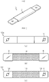
- FIG. 2 is a diagram for illustrating a process of manufacturing an aluminum bus bar according to the present disclosure
- FIG. 3 is a diagram showing an example where the aluminum bus bar of FIG. 2 is installed for cooling.
- a bus bar according to the present disclosure is an aluminum bus bar 100, which includes an insulation portion 110 having an oxide film insulation layer and electric conduction portions 120 having electric conductivity and disposed with the insulation portion 110 being interposed therebetween.
- the insulation portion 110 is a region other than the electric conduction portion 120, and a surface of the insulation portion 110 may be formed as an aluminum oxide (Al 2 O 3 ) layer.
- the aluminum oxide layer may be formed by anodizing the surface of the aluminum bus bar 100.
- anodizing is a post-treatment method for the surface of aluminum, and a natural oxidation process that occurs when aluminum meets oxygen is artificially performed using an electro-chemical reaction to apply an oxide coating on the surface of aluminum. For example, if an electrode is connected to aluminum and immersing in an electrolyte, an aluminum oxide film may be evenly coated.
- a bus bar 100a having certain thickness, width and length is manufactured using aluminum.
- the electric conduction portions 120 are parts corresponding to both ends of the aluminum bus bar 100 and respectively have a hole 101.
- the hole 101 may be used to insert a bolt B when the bus bar is connected to a terminal of an external device or another bus bar.
- a straight bus bar is manufactured as an example, but the bus bar may be manufactured to have various paths by bending, twisting, or the like depending on the location where the bus bar is to be used.
- a masking tape M is attached to the electric conduction portion 120, or the electric conduction portion 120 is masked using a chemical masking agent, and the surface of the other region of the bus bar is anodized.
- Aluminum oxide exhibits corrosion resistance, abrasion resistance and electrical insulation, and has a high thermal conductivity of about 20 W/mk.
- the insulation portion 110 is surface-treated with the aluminum oxide, so even if the surface of the insulation portion 110 comes into contact with a metal, the insulation portion 110 is not electrically connected to the metal.
- the aluminum bus bar 100 heats by itself, the heat may be smoothly dissipated to the outside through the aluminum oxide layer of the insulation portion 110.
- the anodized aluminum bus bar 100 according to the present disclosure has excellent insulation and heat dissipation as described above, so the aluminum bus bar 100 according to the present disclosure may directly contact the cooling plate or the heatsink 300.
- the aluminum bus bar 100 of the present disclosure may be connected to the electrode terminal of the electric component 400 or other bus bars T1, T2 by fastening the bolt B.
- the aluminum bus bar 100 may be mounted to a partially opened electric component housing 500, and the insulation portion 110 of the aluminum bus bar 100 may be in contact with the heatsink 300 through the opened space.
- a thermally conductive pad 600 may be further interposed therebetween.
- the heatsink 300 is not particularly limited as long as it is capable of contacting the aluminum bus bar 100 and absorbing heat from the aluminum bus bar 100, and in this embodiment, a cooling plate having a plurality of flow paths 310 therein is used as the heatsink 300.
- FIG. 4 is a partial perspective view schematically showing a battery module according to an embodiment of the present disclosure
- FIG. 5 is a sectional view, taken along the line I-I' of FIG. 4
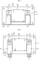
- FIG. 6 is a plan view schematically showing a portion of an electric component housing of the battery module according to an embodiment of the present disclosure
- FIG. 7 is a plan view showing that the aluminum bus bar is connected to an electric component of FIG. 6 .
- the battery module 10 may include at least one aluminum bus bar 100, a cell assembly 200, a heatsink 300, an electric component 400, and an electric component housing 500..
- the cell assembly 200 may include a plurality of battery cells 210 and a cell case 220 for accommodating the battery cells 210 in an inner space thereof.
- a pouch-type secondary battery may be employed as the battery cell 210.
- the pouch-type secondary battery cells may be stacked and arranged in the inner space of the cell case 220, which is advantageous in increasing energy density.
- the pouch-type secondary battery cells may be accommodated such that edges of each cell are in contact with the cell case 220, so the heat of each cell may be dissipated to the heatsink 300 through the cell case 220.
- the battery cell 210 is not limited as a pouch-type battery cell 210.
- a cylindrical secondary battery cell or a rectangular secondary battery cell may also be employed.
- the cell case 220 plays a role of accommodating the battery cells 210 and protecting them from external shocks.
- the cell case 220 may be preferably made of a metal material so as to have impact resistance and smoothly dissipate heat from the battery cells 210.
- the heatsink 300 is disposed at one side of the cell assembly 200 to exchange heat with the cell assembly 200.
- the heatsink 300 of this embodiment may have a flow path through which a coolant flows, so as to absorb surrounding heat. Water with high latent heat is preferable as the coolant, but any material capable of absorbing heat while flowing along the flow path may be used.
- the electric component 400 is a component for controlling the operation of the battery cells 210, and may be, for example, a relay for controlling the current of the battery module 10 or a current sensor for detecting the magnitude of the current.
- the electric component 400 may be accommodated or installed in the electric component housing 500, and the electric component housing 500 may be coupled to the cell case 220 or the heatsink 300.
- the electric component 400 may be electrically connected to the cell assembly 200 by means of the aluminum bus bar 100.
- an electrode terminal (not shown) of the cell assembly 200 and an electrode terminal 410 of the relay may be connected by the aluminum bus bar 100. That is, the aluminum bus bar 100 serves to form a current path between the electrode terminal (not shown) of the cell assembly 200 and the electrode terminal 410 of the relay.
- the insulation portion 110 of the aluminum bus bar 100 is in contact with one surface of the heatsink 300 and the cell case 220 is in contact with the other surface of the heatsink 300 such that the aluminum bus bar 100 and the battery cells 210 may be cooled simultaneously by one heatsink 300.
- the assembly structure of the battery module 10 for cooling the aluminum bus bar 100 to the heatsink 300 for cooling the battery cells 210 will be described in detail as follows.
- the electric component housing 500 includes a plate-shaped base plate 510 in surface contact with the heatsink 300.
- the electric component 400 such as a relay may be installed at the center of the base plate 510.
- the base plate 510 is provided with a larger area and an additional electric component 400 may be installed further.
- the electric component housing 500 may further include a housing cover (not shown) covering an upper portion of the base plate 510.
- the base plate 510 of this embodiment has a tunnel portion 511 for efficiently fixing and connecting the aluminum bus bar 100.
- the tunnel portion 511 is a portion formed convexly from the edge of the base plate 510 toward the center rather than the other portion of the base plate 510.
- the tunnel portion 511 may be regarded as a portion having an uneven structure on the base plate 510.
- a bus bar passing hole 513 is provided through the plate surface of the base plate 510.
- a part of the insulation portion 110 may be interposed in the tunnel portion 511, and the electric conduction portion 120 may be bent at a right angle at the insulation portion 110, pass through the bus bar passing hole 513 and is then bent again so as to be disposed on the upper surface of the electrode terminal of the electric component 400.
- the aluminum bus bar 100 may be assembled with the electric component housing 500 in a structure where a part of the insulation portion 110 is interposed in the tunnel portion 511 and placed in a state of holding the rear surface of the base plate 510 and the electric conduction portion 120 is fixed to the electrode terminal of the electric component 400 by a bolt B at the front surface of the base plate 510.
- the aluminum bus bar 100, the electric component 400 and the electric component housing 500 assembled as described above may be integrally fixed to the cell assembly 200 to which the heatsink 300 is attached.
- a method of matching bolt fastening holes 512 of the base plate 510 with holes (not shown) of the heatsink 300 for fixing the electric component housing 500 and then fastening the bolts B may be adopted.
- the part of the insulation portion 110 interposed in the tunnel portion 511 comes into contact with one surface of the heatsink 300 in a state of being covered and pressed by the base plate 510, so it will be understood that the contact and fixability between the insulation portion 110 of the aluminum bus bar 100 and the heatsink 300 may be sufficiently secured.
- a silicone gel-type thermally conductive pad 600 may be further interposed between the insulation portion 110 of the aluminum bus bar 100 and the heatsink 300 to further enhance contact, fixability and thermal conductivity.
- the battery module 10 of the present disclosure having the above configuration may not only properly manage the temperature of the battery cells 210 but also cool the aluminum bus bar 100 in direct contact with the heatsink 300 by using the anodized aluminum bus bar 100, thereby further improving the electrical safety.
- the battery module 10 of the present disclosure simultaneously cools the bus bar and the battery cells 210 with one heatsink 300, it is possible to reduce the number of cooling parts and improve space efficiency accordingly.
- a battery pack according to the present disclosure may be configured to include at least one battery module 10 according to the present disclosure described above.
- the battery pack may further include various devices for controlling charging and discharging of each battery module 10, for example as a BMS, a current sensor, a fuse and the like.
- the battery pack may be applied to vehicles such as an electric vehicle or a hybrid electric vehicle. Also, the battery pack may be applied to energy storage systems or other IT products.
Landscapes
- Chemical & Material Sciences (AREA)
- Chemical Kinetics & Catalysis (AREA)
- Electrochemistry (AREA)
- General Chemical & Material Sciences (AREA)
- Engineering & Computer Science (AREA)
- Manufacturing & Machinery (AREA)
- Inorganic Chemistry (AREA)
- Connection Of Batteries Or Terminals (AREA)
- Secondary Cells (AREA)
- Battery Mounting, Suspending (AREA)
Abstract
Description
- The present disclosure relates to a bus bar and a battery module including the bus bar, and more particularly, to a battery module using a bus bar having excellent insulation and heat dissipation performance as an electric connection means.
- The present application claims priority to
Korean Patent Application No. 10-2019-0098321 filed on August 12, 2019 - Secondary batteries currently commercialized include nickel cadmium batteries, nickel hydrogen batteries, nickel zinc batteries, lithium secondary batteries and so on. Among them, the lithium secondary batteries are more highlighted in comparison to nickel-based secondary batteries due to advantages such as free charging and discharging, caused by substantially no memory effect, very low self-discharge rate, and high energy density.
- Recently, secondary batteries are widely used not only in small devices such as portable electronic devices but also in middle-sized or large-sized devices such as vehicles and energy storage devices (ESS). When used in such a medium-sized or large-sized device, a large number of secondary batteries are electrically connected to form a battery module or a battery pack in order to increase capacity and output.
- Meanwhile, a bus bar is widely used as an electrical connection means for high current connection of a battery module or a battery pack.
- The bus bar generally has a bar shape made of metal with certain width, thickness and length and good electrical conductivity, and has safety and low energy loss even when high current is applied thereto. Since high current commonly flows in the bus bar, in case where the bus bar is used without insulation or covering, there is a risk of electric shock if a worker is not careful when assembling, repairing or replacing the bus bar. Thus, as shown in
FIG. 1 , a bus bar 1 is wrapped with atube 2 or a plastic cover to secure insulation. - However, if the current flowing through the bus bar 1 has very strong intensity, the
tube 2 or the plastic cover may melt due to the self-heating of the bus bar not to function normally. Further, the heat of the bus bar may cause thetube 2 or the plastic cover to ignite and spread damage to the surroundings. - To prevent this phenomenon in advance, it is necessary to cool the bus bar 1 such that its temperature is managed below a certain temperature. However, even if the conventional bus bar 1 is in direct contact with a cooling medium such as a heatsink to cool the same, since the contact area of the bus bar 1 has insulation and is wrapped with a tube or plastic with low thermal conductivity of less than 1 W/mK, the heat is not transferred well.
- The present disclosure is directed to effectively managing insulation and heat dissipation of a bus bar and further securing the safety of a battery module.
- Other objects and advantages of the present disclosure will be described below, and will be appreciated by embodiments of the present disclosure. In addition, the objects and advantages of the present disclosure can be realized by components defined in the claims and a combination thereof.
- In one aspect of the present disclosure, there is provided an aluminum bus bar, comprising: an insulation portion having an oxide film insulation layer; and electric conduction portions having electric conductivity and disposed with the insulation portion being interposed therebetween.
- The insulation portion may have an aluminum oxide (Al2O3) layer formed on a surface thereof as the oxide film insulation layer.
- In another aspect of the present disclosure, there is also provided a battery module, comprising: the aluminum bus bar; a cell assembly having battery cells; an electric component electrically connected to the cell assembly by means of the aluminum bus bar; and a heatsink disposed at one side of the cell assembly to exchange heat with the cell assembly, wherein the insulation portion of the aluminum bus bar is disposed in contact with one surface of the heatsink.
- The battery module may further comprise an electric component housing in which the electric component is installed, one of the electric conduction portions of the aluminum bus bar may be mounted to the electric component housing, and the electric component housing may be mounted to the heatsink.
- The electric component housing ma includes a base plate in surface contact with the heatsink, the base plate may have a tunnel portion formed convex rather than the other portion thereof and extending from an edge thereof toward a center thereof, and a part of the insulation portion may be interposed and held in the tunnel portion.
- A part of the insulation portion may be disposed in contact with one surface of the heatsink and covered with the base plate.
- A bus bar passing hole may be formed in front of an end of the tunnel portion through a plate surface of the base plate, and the electric conduction portion may pass through the bus bar passing hole and be bent at least once to be connected to an electrode terminal of the electric component.
- The cell assembly may further include a cell case configured to accommodate the battery cells therein, and the cell case is in contact with the other surface of the heatsink.
- The battery module may further comprise a silicone gel-type thermally conductive pad interposed between the insulation portion of the aluminum bus bar and the heatsink.
- In still another aspect of the present disclosure, there is also provided a battery pack, comprising the battery module described above.
- According to one aspect of the present disclosure, a bus bar having excellent insulation and heat dissipation may be provided.
- According to another aspect of the present disclosure, temperature of the bus bar and the battery cells may be managed, thereby providing a battery module with improved safety.
- In particular, since the battery module simultaneously cools the bus bar and the battery cells with one heatsink, it is possible to reduce the number of cooling components and improve space efficiency.
- The effects of the present disclosure are not limited to the above, and effects not mentioned herein may be clearly understood from the present specification and the accompanying drawings by those skilled in the art.
-
-
FIG. 1 is a perspective view showing a conventional bus bar. -
FIG. 2 is a diagram for illustrating a process of manufacturing an aluminum bus bar according to the present disclosure. -
FIG. 3 is a diagram showing an example where the aluminum bus bar ofFIG. 2 is installed for cooling. -
FIG. 4 is a partial perspective view schematically showing a battery module according to an embodiment of the present disclosure. -
FIG. 5 is a sectional view, taken along the line I-I' ofFIG. 4 . -
FIG. 6 is a plan view schematically showing a portion of an electric component housing of the battery module according to an embodiment of the present disclosure. -
FIG. 7 is a plan view showing that the aluminum bus bar is connected to an electric component ofFIG. 6 . - Hereinafter, preferred embodiments of the present disclosure will be described in detail with reference to the accompanying drawings. Prior to the description, it should be understood that the terms used in the specification and the appended claims should not be construed as limited to general and dictionary meanings, but interpreted based on the meanings and concepts corresponding to technical aspects of the present disclosure on the basis of the principle that the inventor is allowed to define terms appropriately for the best explanation. Therefore, the description proposed herein is just a preferable example for the purpose of illustrations only, not intended to limit the scope of the disclosure, so it should be understood that other equivalents and modifications could be made thereto without departing from the scope of the disclosure.
- The embodiments disclosed herein are provided for more perfect explanation of the present disclosure, and thus the shape, size and the like of components may be exaggerated, omitted or simplified in the drawings for better understanding. Thus, the size and ratio of components in the drawings do not wholly reflect the actual size and ratio.
-
FIG. 2 is a diagram for illustrating a process of manufacturing an aluminum bus bar according to the present disclosure, andFIG. 3 is a diagram showing an example where the aluminum bus bar ofFIG. 2 is installed for cooling. - Referring to these figures, a bus bar according to the present disclosure is an
aluminum bus bar 100, which includes aninsulation portion 110 having an oxide film insulation layer andelectric conduction portions 120 having electric conductivity and disposed with theinsulation portion 110 being interposed therebetween. - The
insulation portion 110 is a region other than theelectric conduction portion 120, and a surface of theinsulation portion 110 may be formed as an aluminum oxide (Al2O3) layer. The aluminum oxide layer may be formed by anodizing the surface of thealuminum bus bar 100. Here, anodizing is a post-treatment method for the surface of aluminum, and a natural oxidation process that occurs when aluminum meets oxygen is artificially performed using an electro-chemical reaction to apply an oxide coating on the surface of aluminum. For example, if an electrode is connected to aluminum and immersing in an electrolyte, an aluminum oxide film may be evenly coated. - Referring to
FIG. 2 , a process of manufacturing thealuminum bus bar 100 according to the present disclosure will be described briefly as follows. - First, as shown in (a) of
FIG. 2 , abus bar 100a having certain thickness, width and length is manufactured using aluminum. Theelectric conduction portions 120 are parts corresponding to both ends of thealuminum bus bar 100 and respectively have ahole 101. Thehole 101 may be used to insert a bolt B when the bus bar is connected to a terminal of an external device or another bus bar. - In this embodiment, a straight bus bar is manufactured as an example, but the bus bar may be manufactured to have various paths by bending, twisting, or the like depending on the location where the bus bar is to be used.
- After that, as shown in (b) of
FIG. 2 , a masking tape M is attached to theelectric conduction portion 120, or theelectric conduction portion 120 is masked using a chemical masking agent, and the surface of the other region of the bus bar is anodized. - After that, as shown in (c) of
FIG. 2 , the masking tape is removed, thereby completing the process for manufacturing an aluminum bus bar. - Aluminum oxide exhibits corrosion resistance, abrasion resistance and electrical insulation, and has a high thermal conductivity of about 20 W/mk. In the
aluminum bus bar 100 according to the present disclosure, theinsulation portion 110 is surface-treated with the aluminum oxide, so even if the surface of theinsulation portion 110 comes into contact with a metal, theinsulation portion 110 is not electrically connected to the metal. In addition, when thealuminum bus bar 100 heats by itself, the heat may be smoothly dissipated to the outside through the aluminum oxide layer of theinsulation portion 110. - An example where the
aluminum bus bar 100 is used will be described with reference toFIG. 3 . - It is very difficult or impossible to allow a typical aluminum or copper bus bar to make direct contact with a cooling plate or a
heatsink 300 due to insulation or coating problems. However, the anodizedaluminum bus bar 100 according to the present disclosure has excellent insulation and heat dissipation as described above, so thealuminum bus bar 100 according to the present disclosure may directly contact the cooling plate or theheatsink 300. - For example, as shown in
FIG. 3 , thealuminum bus bar 100 of the present disclosure may be connected to the electrode terminal of theelectric component 400 or other bus bars T1, T2 by fastening the bolt B. - For reference, since the aluminum oxide layer described above is provided on the surface of the
insulation portion 110, there is no problem in electric connection through thealuminum bus bar 100, like the current flow line shown inFIG. 3 . - As a bus bar cooling configuration to dissipate heat caused by high current flowing through the
aluminum bus bar 100, thealuminum bus bar 100 may be mounted to a partially openedelectric component housing 500, and theinsulation portion 110 of thealuminum bus bar 100 may be in contact with theheatsink 300 through the opened space. In addition, in order to further increase the thermal conductivity between theinsulation portion 110 and theheatsink 300, a thermallyconductive pad 600 may be further interposed therebetween. - The
heatsink 300 is not particularly limited as long as it is capable of contacting thealuminum bus bar 100 and absorbing heat from thealuminum bus bar 100, and in this embodiment, a cooling plate having a plurality offlow paths 310 therein is used as theheatsink 300. -
FIG. 4 is a partial perspective view schematically showing a battery module according to an embodiment of the present disclosure,FIG. 5 is a sectional view, taken along the line I-I' ofFIG. 4 ,FIG. 6 is a plan view schematically showing a portion of an electric component housing of the battery module according to an embodiment of the present disclosure, andFIG. 7 is a plan view showing that the aluminum bus bar is connected to an electric component ofFIG. 6 . - Hereinafter, a
battery module 10 to which thealuminum bus bar 100 described above is applied will be described in more detail with reference to the features. - Referring to
FIG. 4 , thebattery module 10 according to an embodiment of the present disclosure may include at least onealuminum bus bar 100, acell assembly 200, aheatsink 300, anelectric component 400, and anelectric component housing 500.. - The
cell assembly 200 may include a plurality ofbattery cells 210 and acell case 220 for accommodating thebattery cells 210 in an inner space thereof. - As the
battery cell 210, a pouch-type secondary battery may be employed. The pouch-type secondary battery cells may be stacked and arranged in the inner space of thecell case 220, which is advantageous in increasing energy density. - In addition, the pouch-type secondary battery cells may be accommodated such that edges of each cell are in contact with the
cell case 220, so the heat of each cell may be dissipated to theheatsink 300 through thecell case 220. Here, thebattery cell 210 is not limited as a pouch-type battery cell 210. For example, a cylindrical secondary battery cell or a rectangular secondary battery cell may also be employed. - The
cell case 220 plays a role of accommodating thebattery cells 210 and protecting them from external shocks. Thecell case 220 may be preferably made of a metal material so as to have impact resistance and smoothly dissipate heat from thebattery cells 210. - The
heatsink 300 is disposed at one side of thecell assembly 200 to exchange heat with thecell assembly 200. Theheatsink 300 of this embodiment may have a flow path through which a coolant flows, so as to absorb surrounding heat. Water with high latent heat is preferable as the coolant, but any material capable of absorbing heat while flowing along the flow path may be used. - The
electric component 400 is a component for controlling the operation of thebattery cells 210, and may be, for example, a relay for controlling the current of thebattery module 10 or a current sensor for detecting the magnitude of the current. Theelectric component 400 may be accommodated or installed in theelectric component housing 500, and theelectric component housing 500 may be coupled to thecell case 220 or theheatsink 300. - The
electric component 400 may be electrically connected to thecell assembly 200 by means of thealuminum bus bar 100. For example, an electrode terminal (not shown) of thecell assembly 200 and anelectrode terminal 410 of the relay may be connected by thealuminum bus bar 100. That is, thealuminum bus bar 100 serves to form a current path between the electrode terminal (not shown) of thecell assembly 200 and theelectrode terminal 410 of the relay. - In particular, as shown in
FIGS. 4 and5 , in thebattery module 10 according to the present disclosure, theinsulation portion 110 of thealuminum bus bar 100 is in contact with one surface of theheatsink 300 and thecell case 220 is in contact with the other surface of theheatsink 300 such that thealuminum bus bar 100 and thebattery cells 210 may be cooled simultaneously by oneheatsink 300. - The assembly structure of the
battery module 10 for cooling thealuminum bus bar 100 to theheatsink 300 for cooling thebattery cells 210 will be described in detail as follows. - As shown in
FIG. 6 , theelectric component housing 500 includes a plate-shapedbase plate 510 in surface contact with theheatsink 300. Theelectric component 400 such as a relay may be installed at the center of thebase plate 510. Although not shown for the convenience of the drawing, thebase plate 510 is provided with a larger area and an additionalelectric component 400 may be installed further. In addition, theelectric component housing 500 may further include a housing cover (not shown) covering an upper portion of thebase plate 510. - The
base plate 510 of this embodiment has atunnel portion 511 for efficiently fixing and connecting thealuminum bus bar 100. Thetunnel portion 511 is a portion formed convexly from the edge of thebase plate 510 toward the center rather than the other portion of thebase plate 510. In other words, thetunnel portion 511 may be regarded as a portion having an uneven structure on thebase plate 510. In front of an end of thetunnel portion 511, a busbar passing hole 513 is provided through the plate surface of thebase plate 510. - As shown in
FIG. 7 , in thealuminum bus bar 100, a part of theinsulation portion 110 may be interposed in thetunnel portion 511, and theelectric conduction portion 120 may be bent at a right angle at theinsulation portion 110, pass through the busbar passing hole 513 and is then bent again so as to be disposed on the upper surface of the electrode terminal of theelectric component 400. - According to this configuration, the
aluminum bus bar 100 may be assembled with theelectric component housing 500 in a structure where a part of theinsulation portion 110 is interposed in thetunnel portion 511 and placed in a state of holding the rear surface of thebase plate 510 and theelectric conduction portion 120 is fixed to the electrode terminal of theelectric component 400 by a bolt B at the front surface of thebase plate 510. - The
aluminum bus bar 100, theelectric component 400 and theelectric component housing 500 assembled as described above may be integrally fixed to thecell assembly 200 to which theheatsink 300 is attached. For example, a method of matching bolt fastening holes 512 of thebase plate 510 with holes (not shown) of theheatsink 300 for fixing theelectric component housing 500 and then fastening the bolts B may be adopted. - Referring to
FIGS. 4 and5 again, the part of theinsulation portion 110 interposed in thetunnel portion 511 comes into contact with one surface of theheatsink 300 in a state of being covered and pressed by thebase plate 510, so it will be understood that the contact and fixability between theinsulation portion 110 of thealuminum bus bar 100 and theheatsink 300 may be sufficiently secured. - In addition, a silicone gel-type thermally
conductive pad 600 may be further interposed between theinsulation portion 110 of thealuminum bus bar 100 and theheatsink 300 to further enhance contact, fixability and thermal conductivity. - The
battery module 10 of the present disclosure having the above configuration may not only properly manage the temperature of thebattery cells 210 but also cool thealuminum bus bar 100 in direct contact with theheatsink 300 by using the anodizedaluminum bus bar 100, thereby further improving the electrical safety. - In particular, since the
battery module 10 of the present disclosure simultaneously cools the bus bar and thebattery cells 210 with oneheatsink 300, it is possible to reduce the number of cooling parts and improve space efficiency accordingly. - Meanwhile, a battery pack according to the present disclosure may be configured to include at least one
battery module 10 according to the present disclosure described above. The battery pack may further include various devices for controlling charging and discharging of eachbattery module 10, for example as a BMS, a current sensor, a fuse and the like. - The battery pack may be applied to vehicles such as an electric vehicle or a hybrid electric vehicle. Also, the battery pack may be applied to energy storage systems or other IT products.
- The present disclosure has been described in detail. However, it should be understood that the detailed description and specific examples, while indicating preferred embodiments of the disclosure, are given by way of illustration only, since various changes and modifications within the scope of the disclosure will become apparent to those skilled in the art from this detailed description.
- Meanwhile, even though the terms expressing directions such as "upper", "lower", "left" and "right" are used in the specification, they are just for convenience of description and can be expressed differently depending on the location of a viewer or a subject, as apparent to those skilled in the art.
Claims (10)
- An aluminum bus bar, comprising:an insulation portion having an oxide film insulation layer; andelectric conduction portions having electric conductivity and disposed with the insulation portion being interposed therebetween.
- The aluminum bus bar according to claim 1,
wherein the insulation portion has an aluminum oxide (Al2O3) layer formed on a surface thereof as the oxide film insulation layer. - A battery module, comprising:the aluminum bus bar according to claim 1;a cell assembly having battery cells;an electric component electrically connected to the cell assembly by means of the aluminum bus bar; anda heatsink disposed at one side of the cell assembly to exchange heat with the cell assembly,wherein the insulation portion of the aluminum bus bar is disposed in contact with one surface of the heatsink.
- The battery module according to claim 3, further comprising:an electric component housing in which the electric component is installed,wherein one of the electric conduction portions of the aluminum bus bar is mounted to the electric component housing, andthe electric component housing is mounted to the heatsink.
- The battery module according to claim 4,wherein the electric component housing includes a base plate in surface contact with the heatsink, and the base plate has a tunnel portion formed convex rather than the other portion thereof and extending from an edge thereof toward a center thereof, anda part of the insulation portion is interposed and held in the tunnel portion.
- The battery module according to claim 5,
wherein a part of the insulation portion is disposed in contact with one surface of the heatsink and covered with the base plate. - The battery module according to claim 5,
wherein a bus bar passing hole is formed in front of an end of the tunnel portion through a plate surface of the base plate, and the electric conduction portion passes through the bus bar passing hole and is bent at least once to be connected to an electrode terminal of the electric component. - The battery module according to claim 3,
wherein the cell assembly further includes a cell case configured to accommodate the battery cells therein, and the cell case is in contact with the other surface of the heatsink. - The battery module according to claim 3, further comprising:
a silicone gel-type thermally conductive pad interposed between the insulation portion of the aluminum bus bar and the heatsink. - A battery pack, comprising the battery module according to any one of claims 3 to 9.
Applications Claiming Priority (2)
| Application Number | Priority Date | Filing Date | Title |
|---|---|---|---|
| KR1020190098321A KR102780571B1 (en) | 2019-08-12 | 2019-08-12 | A bus bar with excellent insulation and heat dissipation performance and battery module with same |
| PCT/KR2020/009559 WO2021029549A1 (en) | 2019-08-12 | 2020-07-20 | Busbar having excellent insulation and heat dissipation performance and battery module comprising same |
Publications (2)
| Publication Number | Publication Date |
|---|---|
| EP3993141A1 true EP3993141A1 (en) | 2022-05-04 |
| EP3993141A4 EP3993141A4 (en) | 2022-08-31 |
Family
ID=74571009
Family Applications (1)
| Application Number | Title | Priority Date | Filing Date |
|---|---|---|---|
| EP20851717.7A Pending EP3993141A4 (en) | 2019-08-12 | 2020-07-20 | BUS BAR WITH EXCELLENT INSULATION AND HEAT DISSIPATION PERFORMANCE, AND BATTERY MODULE COMPRISING THE SAME |
Country Status (6)
| Country | Link |
|---|---|
| US (1) | US12176578B2 (en) |
| EP (1) | EP3993141A4 (en) |
| JP (1) | JP7235221B2 (en) |
| KR (1) | KR102780571B1 (en) |
| CN (1) | CN113728507B (en) |
| WO (1) | WO2021029549A1 (en) |
Cited By (2)
| Publication number | Priority date | Publication date | Assignee | Title |
|---|---|---|---|---|
| EP4391745A1 (en) * | 2022-12-22 | 2024-06-26 | Prime Planet Energy & Solutions, Inc. | Electric device and battery pack system |
| EP4300726A4 (en) * | 2022-05-19 | 2024-10-23 | Lg Energy Solution, Ltd. | FLEXIBLE BUSBAR WITH COVER ELEMENT TO PREVENT CORROSION AND BATTERY MODULE SO |
Families Citing this family (25)
| Publication number | Priority date | Publication date | Assignee | Title |
|---|---|---|---|---|
| KR20220052609A (en) * | 2020-10-21 | 2022-04-28 | 주식회사 엘지에너지솔루션 | Battery disconnect unit and battery pack including the same |
| US11670929B2 (en) * | 2021-06-02 | 2023-06-06 | Schaeffler Technologies AG & Co. KG | Heat dissipation and sealing configuration for junction assembly |
| KR102856144B1 (en) * | 2021-07-15 | 2025-09-04 | 주식회사 엘지에너지솔루션 | Battery pack and vehicle including the same |
| KR102928820B1 (en) * | 2021-08-20 | 2026-02-19 | 주식회사 엘지에너지솔루션 | Battery module and battery pack including the same |
| CN116420271A (en) * | 2021-10-22 | 2023-07-11 | 宁德时代新能源科技股份有限公司 | Battery, electric device, method and device for preparing battery cell |
| CN114221058B (en) * | 2021-10-29 | 2024-05-14 | 浙江南都电源动力股份有限公司 | Aluminum row heat conduction device and composite aluminum row |
| KR20230118390A (en) * | 2022-02-04 | 2023-08-11 | 현대자동차주식회사 | Battery system for vehicle |
| JP7486096B2 (en) * | 2022-02-24 | 2024-05-17 | パナソニックIpマネジメント株式会社 | Battery Disconnect Unit |
| EP4393029A2 (en) * | 2022-05-04 | 2024-07-03 | Aspen Aerogels Inc. | Protection of electrical components in battery systems |
| CN217468723U (en) * | 2022-06-22 | 2022-09-20 | 宁德时代新能源科技股份有限公司 | Batteries and Electrical Devices |
| KR102881209B1 (en) * | 2022-08-16 | 2025-11-05 | 주식회사 엘지에너지솔루션 | Inter-module busbar with digestive fluid |
| WO2024054098A1 (en) * | 2022-09-08 | 2024-03-14 | 주식회사 엘지에너지솔루션 | Busbar having improved flame resistance, and battery pack including same |
| JP2025541411A (en) * | 2022-12-26 | 2025-12-18 | エルジー エナジー ソリューション リミテッド | Battery module and battery pack including the same |
| KR102950881B1 (en) * | 2023-03-21 | 2026-04-09 | 주식회사 엘지에너지솔루션 | Intermodule busbar |
| DE102023108560A1 (en) * | 2023-04-04 | 2024-10-10 | Te Connectivity Solutions Gmbh | BUSBAR WITH PHASE CHANGE MATERIAL |
| US20240339733A1 (en) * | 2023-04-06 | 2024-10-10 | GM Global Technology Operations LLC | Busbar for high conductivity distribution of electrical power within an electric vehicle |
| KR20240166152A (en) * | 2023-05-17 | 2024-11-26 | 주식회사 엘지에너지솔루션 | Busbar assembly and battery pack including the same |
| KR20250013054A (en) * | 2023-07-18 | 2025-01-31 | 주식회사 엘지에너지솔루션 | Connector and battery module comprising the connector |
| KR20250022486A (en) * | 2023-08-08 | 2025-02-17 | 주식회사 엘지에너지솔루션 | Busbar assembly and battery pack including the same |
| USD1082698S1 (en) * | 2023-08-08 | 2025-07-08 | The Noco Company | Busbar for a battery |
| KR102602736B1 (en) | 2023-08-30 | 2023-11-15 | (주)디에스시 | Bus bar with excellent preventing thermal runaway function for electric vehicle |
| CN120358699A (en) * | 2024-01-19 | 2025-07-22 | 宁德时代新能源科技股份有限公司 | Battery distribution box, battery and electricity utilization device |
| USD1100858S1 (en) * | 2024-02-26 | 2025-11-04 | Kyungshin Corp. | Busbar for power distribution controller |
| KR20250136513A (en) * | 2024-03-08 | 2025-09-16 | 주식회사 엘지에너지솔루션 | Intervus bar, pack housing including it, bettery pack including it, and method manufacturing the same |
| WO2025203118A1 (en) * | 2024-03-29 | 2025-10-02 | Eicher Motors Limited | A bus bar for a battery module, a battery pack and a method of manufacturing the same |
Family Cites Families (24)
| Publication number | Priority date | Publication date | Assignee | Title |
|---|---|---|---|---|
| JP3419673B2 (en) | 1998-01-16 | 2003-06-23 | 株式会社オートネットワーク技術研究所 | Conductive connector and method for forming coating film of conductive connector |
| WO2008099602A1 (en) * | 2007-02-16 | 2008-08-21 | Panasonic Corporation | Electric storage unit |
| JP4935735B2 (en) | 2008-03-26 | 2012-05-23 | トヨタ自動車株式会社 | Bus bar and manufacturing method thereof |
| WO2010114311A2 (en) | 2009-04-01 | 2010-10-07 | 주식회사 엘지화학 | Battery module having improved safety |
| JP5434757B2 (en) | 2010-04-02 | 2014-03-05 | 株式会社デンソー | DC-DC converter |
| JP2012058199A (en) * | 2010-09-13 | 2012-03-22 | Sumitomo Wiring Syst Ltd | Current detection apparatus |
| KR101085284B1 (en) | 2011-01-26 | 2011-11-22 | 허만욱 | How to make a booth bar |
| JP6075784B2 (en) | 2012-12-28 | 2017-02-08 | 株式会社神戸製鋼所 | Busbar, busbar module, and busbar manufacturing method |
| JP2014216248A (en) | 2013-04-26 | 2014-11-17 | 三菱自動車工業株式会社 | Battery case |
| JP5979074B2 (en) | 2013-05-08 | 2016-08-24 | 株式会社オートネットワーク技術研究所 | Power storage module |
| JP6015573B2 (en) * | 2013-06-26 | 2016-10-26 | 株式会社デンソー | Cooling system |
| JP5846166B2 (en) * | 2013-07-29 | 2016-01-20 | 株式会社デンソー | Battery pack |
| US10487413B2 (en) | 2013-12-03 | 2019-11-26 | Schneider Electric It Corporation | System for insulating high current busbars |
| KR20150143060A (en) | 2014-06-13 | 2015-12-23 | 주식회사 메가테크 | Bus bar united by covering member |
| US9147875B1 (en) * | 2014-09-10 | 2015-09-29 | Cellink Corporation | Interconnect for battery packs |
| KR101655562B1 (en) | 2014-11-05 | 2016-09-08 | 현대자동차주식회사 | Aluminium bus bar and manufacturing methods thereof |
| JP6439710B2 (en) * | 2016-01-27 | 2018-12-19 | 株式会社オートネットワーク技術研究所 | Busbar module |
| KR102018719B1 (en) | 2016-02-12 | 2019-09-04 | 주식회사 엘지화학 | Busbar for cooling battery cell and battery module using thereof |
| JP6658387B2 (en) * | 2016-07-29 | 2020-03-04 | 株式会社デンソー | Battery pack |
| JP6720847B2 (en) * | 2016-12-14 | 2020-07-08 | 株式会社デンソー | Battery pack |
| EP3557602B1 (en) | 2016-12-15 | 2024-04-24 | Amogreentech Co., Ltd. | Power relay assembly |
| JP6724846B2 (en) * | 2017-03-31 | 2020-07-15 | 株式会社デンソー | Heat dissipation device for battery pack and bus bar |
| KR102083801B1 (en) | 2018-02-14 | 2020-03-03 | 퍼스트통신 주식회사 | Stretch Line Combiner |
| CN208589746U (en) * | 2018-06-29 | 2019-03-08 | 江苏华威线路设备集团有限公司 | A kind of isolated bus heat radiating installation construction |
-
2019
- 2019-08-12 KR KR1020190098321A patent/KR102780571B1/en active Active
-
2020
- 2020-07-20 JP JP2021545692A patent/JP7235221B2/en active Active
- 2020-07-20 EP EP20851717.7A patent/EP3993141A4/en active Pending
- 2020-07-20 CN CN202080031114.6A patent/CN113728507B/en active Active
- 2020-07-20 WO PCT/KR2020/009559 patent/WO2021029549A1/en not_active Ceased
- 2020-07-20 US US17/442,679 patent/US12176578B2/en active Active
Cited By (2)
| Publication number | Priority date | Publication date | Assignee | Title |
|---|---|---|---|---|
| EP4300726A4 (en) * | 2022-05-19 | 2024-10-23 | Lg Energy Solution, Ltd. | FLEXIBLE BUSBAR WITH COVER ELEMENT TO PREVENT CORROSION AND BATTERY MODULE SO |
| EP4391745A1 (en) * | 2022-12-22 | 2024-06-26 | Prime Planet Energy & Solutions, Inc. | Electric device and battery pack system |
Also Published As
| Publication number | Publication date |
|---|---|
| US20220166114A1 (en) | 2022-05-26 |
| CN113728507A (en) | 2021-11-30 |
| JP2022543718A (en) | 2022-10-14 |
| KR20210019295A (en) | 2021-02-22 |
| KR102780571B1 (en) | 2025-03-11 |
| JP7235221B2 (en) | 2023-03-08 |
| CN113728507B (en) | 2023-06-09 |
| WO2021029549A1 (en) | 2021-02-18 |
| US12176578B2 (en) | 2024-12-24 |
| EP3993141A4 (en) | 2022-08-31 |
Similar Documents
| Publication | Publication Date | Title |
|---|---|---|
| US12176578B2 (en) | Bus bar having excellent insulation and heat dissipation performance and battery module including the same | |
| US20250023141A1 (en) | Battery module and manufacturing method thereof | |
| EP4007042B1 (en) | Upper part cooling-type battery pack | |
| US10622688B2 (en) | Coolant direct-contact cooling-type battery pack | |
| KR102762539B1 (en) | Busbar Frame Assembly and Battery module including the same | |
| JP5209036B2 (en) | Battery assembly, electric vehicle, and battery housing | |
| KR20190064835A (en) | Battery pack | |
| US12548833B2 (en) | Battery module and battery pack comprising same | |
| EP4191780A1 (en) | Battery module comprising multiple parallel battery cells | |
| US12548822B2 (en) | Battery pack and device including the same | |
| EP3920314B1 (en) | Battery pack and vehicle including same | |
| US12482872B2 (en) | Battery module and battery pack including the same | |
| EP3940868A1 (en) | Battery module and battery pack including same | |
| CN115191054B (en) | Battery module and battery including the battery module | |
| US12021212B2 (en) | Battery module, and battery pack and vehicle comprising same | |
| EP3514004B1 (en) | Battery module and battery pack including same | |
| JP2024501574A (en) | A battery module, a battery pack including the battery module, and a vehicle including the battery pack | |
| KR20220075045A (en) | Battery module and battery pack including the same and vehicle including the same |
Legal Events
| Date | Code | Title | Description |
|---|---|---|---|
| STAA | Information on the status of an ep patent application or granted ep patent |
Free format text: STATUS: THE INTERNATIONAL PUBLICATION HAS BEEN MADE |
|
| PUAI | Public reference made under article 153(3) epc to a published international application that has entered the european phase |
Free format text: ORIGINAL CODE: 0009012 |
|
| STAA | Information on the status of an ep patent application or granted ep patent |
Free format text: STATUS: REQUEST FOR EXAMINATION WAS MADE |
|
| 17P | Request for examination filed |
Effective date: 20220128 |
|
| AK | Designated contracting states |
Kind code of ref document: A1 Designated state(s): AL AT BE BG CH CY CZ DE DK EE ES FI FR GB GR HR HU IE IS IT LI LT LU LV MC MK MT NL NO PL PT RO RS SE SI SK SM TR |
|
| A4 | Supplementary search report drawn up and despatched |
Effective date: 20220728 |
|
| RIC1 | Information provided on ipc code assigned before grant |
Ipc: H01R 4/02 20060101ALI20220722BHEP Ipc: H01L 23/00 20060101ALI20220722BHEP Ipc: H01M 50/50 20210101ALI20220722BHEP Ipc: H01M 50/20 20210101ALI20220722BHEP Ipc: H01M 10/6551 20140101ALI20220722BHEP Ipc: H01M 10/6553 20140101ALI20220722BHEP Ipc: H01M 10/653 20140101AFI20220722BHEP |
|
| DAV | Request for validation of the european patent (deleted) | ||
| DAX | Request for extension of the european patent (deleted) |