EP3992609B1 - Appareil de traitement d'images, système d'évaluation, support d'enregistrement et procédé de traitement d'images - Google Patents
Appareil de traitement d'images, système d'évaluation, support d'enregistrement et procédé de traitement d'images Download PDFInfo
- Publication number
- EP3992609B1 EP3992609B1 EP20833156.1A EP20833156A EP3992609B1 EP 3992609 B1 EP3992609 B1 EP 3992609B1 EP 20833156 A EP20833156 A EP 20833156A EP 3992609 B1 EP3992609 B1 EP 3992609B1
- Authority
- EP
- European Patent Office
- Prior art keywords
- phase difference
- image
- hologram
- sphere
- optical axis
- Prior art date
- Legal status (The legal status is an assumption and is not a legal conclusion. Google has not performed a legal analysis and makes no representation as to the accuracy of the status listed.)
- Active
Links
- 238000012545 processing Methods 0.000 title claims description 105
- 238000011156 evaluation Methods 0.000 title claims description 64
- 238000003672 processing method Methods 0.000 title claims description 6
- 238000003384 imaging method Methods 0.000 claims description 116
- 230000003287 optical effect Effects 0.000 claims description 80
- 239000008187 granular material Substances 0.000 claims description 52
- 238000009795 derivation Methods 0.000 claims description 31
- 238000000605 extraction Methods 0.000 claims description 25
- 238000012935 Averaging Methods 0.000 claims description 21
- 230000000007 visual effect Effects 0.000 claims description 21
- 238000000034 method Methods 0.000 claims description 15
- 230000008569 process Effects 0.000 claims description 4
- 238000005516 engineering process Methods 0.000 description 51
- 210000004027 cell Anatomy 0.000 description 49
- 230000006870 function Effects 0.000 description 30
- 238000010586 diagram Methods 0.000 description 29
- 230000003833 cell viability Effects 0.000 description 13
- 239000000284 extract Substances 0.000 description 11
- 239000002245 particle Substances 0.000 description 10
- 238000004891 communication Methods 0.000 description 9
- 239000002609 medium Substances 0.000 description 6
- 230000002159 abnormal effect Effects 0.000 description 5
- 230000004044 response Effects 0.000 description 5
- 238000001093 holography Methods 0.000 description 4
- 239000013307 optical fiber Substances 0.000 description 4
- 238000001228 spectrum Methods 0.000 description 4
- 239000000126 substance Substances 0.000 description 4
- 238000000684 flow cytometry Methods 0.000 description 3
- 230000035899 viability Effects 0.000 description 3
- XLYOFNOQVPJJNP-UHFFFAOYSA-N water Substances O XLYOFNOQVPJJNP-UHFFFAOYSA-N 0.000 description 3
- 238000005119 centrifugation Methods 0.000 description 2
- 238000012136 culture method Methods 0.000 description 2
- 238000009826 distribution Methods 0.000 description 2
- 230000000694 effects Effects 0.000 description 2
- 230000013632 homeostatic process Effects 0.000 description 2
- 230000001678 irradiating effect Effects 0.000 description 2
- 238000004519 manufacturing process Methods 0.000 description 2
- 238000005259 measurement Methods 0.000 description 2
- 238000005316 response function Methods 0.000 description 2
- 238000010186 staining Methods 0.000 description 2
- 238000003860 storage Methods 0.000 description 2
- 238000012546 transfer Methods 0.000 description 2
- 102000004190 Enzymes Human genes 0.000 description 1
- 108090000790 Enzymes Proteins 0.000 description 1
- GLNADSQYFUSGOU-GPTZEZBUSA-J Trypan blue Chemical compound [Na+].[Na+].[Na+].[Na+].C1=C(S([O-])(=O)=O)C=C2C=C(S([O-])(=O)=O)C(/N=N/C3=CC=C(C=C3C)C=3C=C(C(=CC=3)\N=N\C=3C(=CC4=CC(=CC(N)=C4C=3O)S([O-])(=O)=O)S([O-])(=O)=O)C)=C(O)C2=C1N GLNADSQYFUSGOU-GPTZEZBUSA-J 0.000 description 1
- 239000000654 additive Substances 0.000 description 1
- 230000000996 additive effect Effects 0.000 description 1
- 210000000601 blood cell Anatomy 0.000 description 1
- 238000004422 calculation algorithm Methods 0.000 description 1
- 238000004364 calculation method Methods 0.000 description 1
- 230000001427 coherent effect Effects 0.000 description 1
- 230000000295 complement effect Effects 0.000 description 1
- 230000021615 conjugation Effects 0.000 description 1
- 230000006378 damage Effects 0.000 description 1
- 230000003247 decreasing effect Effects 0.000 description 1
- 238000010494 dissociation reaction Methods 0.000 description 1
- 230000005593 dissociations Effects 0.000 description 1
- 230000005684 electric field Effects 0.000 description 1
- 238000001914 filtration Methods 0.000 description 1
- 239000012530 fluid Substances 0.000 description 1
- 239000001963 growth medium Substances 0.000 description 1
- 238000005304 joining Methods 0.000 description 1
- 238000002032 lab-on-a-chip Methods 0.000 description 1
- 210000000265 leukocyte Anatomy 0.000 description 1
- 229910044991 metal oxide Inorganic materials 0.000 description 1
- 150000004706 metal oxides Chemical class 0.000 description 1
- 210000003463 organelle Anatomy 0.000 description 1
- 239000004065 semiconductor Substances 0.000 description 1
- 238000003892 spreading Methods 0.000 description 1
- 230000007480 spreading Effects 0.000 description 1
- 238000003325 tomography Methods 0.000 description 1
Images


Classifications
-
- G—PHYSICS
- G06—COMPUTING; CALCULATING OR COUNTING
- G06V—IMAGE OR VIDEO RECOGNITION OR UNDERSTANDING
- G06V10/00—Arrangements for image or video recognition or understanding
- G06V10/40—Extraction of image or video features
- G06V10/44—Local feature extraction by analysis of parts of the pattern, e.g. by detecting edges, contours, loops, corners, strokes or intersections; Connectivity analysis, e.g. of connected components
-
- G—PHYSICS
- G03—PHOTOGRAPHY; CINEMATOGRAPHY; ANALOGOUS TECHNIQUES USING WAVES OTHER THAN OPTICAL WAVES; ELECTROGRAPHY; HOLOGRAPHY
- G03H—HOLOGRAPHIC PROCESSES OR APPARATUS
- G03H1/00—Holographic processes or apparatus using light, infrared or ultraviolet waves for obtaining holograms or for obtaining an image from them; Details peculiar thereto
- G03H1/22—Processes or apparatus for obtaining an optical image from holograms
- G03H1/2294—Addressing the hologram to an active spatial light modulator
-
- C—CHEMISTRY; METALLURGY
- C12—BIOCHEMISTRY; BEER; SPIRITS; WINE; VINEGAR; MICROBIOLOGY; ENZYMOLOGY; MUTATION OR GENETIC ENGINEERING
- C12M—APPARATUS FOR ENZYMOLOGY OR MICROBIOLOGY; APPARATUS FOR CULTURING MICROORGANISMS FOR PRODUCING BIOMASS, FOR GROWING CELLS OR FOR OBTAINING FERMENTATION OR METABOLIC PRODUCTS, i.e. BIOREACTORS OR FERMENTERS
- C12M1/00—Apparatus for enzymology or microbiology
- C12M1/34—Measuring or testing with condition measuring or sensing means, e.g. colony counters
-
- C—CHEMISTRY; METALLURGY
- C12—BIOCHEMISTRY; BEER; SPIRITS; WINE; VINEGAR; MICROBIOLOGY; ENZYMOLOGY; MUTATION OR GENETIC ENGINEERING
- C12Q—MEASURING OR TESTING PROCESSES INVOLVING ENZYMES, NUCLEIC ACIDS OR MICROORGANISMS; COMPOSITIONS OR TEST PAPERS THEREFOR; PROCESSES OF PREPARING SUCH COMPOSITIONS; CONDITION-RESPONSIVE CONTROL IN MICROBIOLOGICAL OR ENZYMOLOGICAL PROCESSES
- C12Q1/00—Measuring or testing processes involving enzymes, nucleic acids or microorganisms; Compositions therefor; Processes of preparing such compositions
- C12Q1/02—Measuring or testing processes involving enzymes, nucleic acids or microorganisms; Compositions therefor; Processes of preparing such compositions involving viable microorganisms
- C12Q1/04—Determining presence or kind of microorganism; Use of selective media for testing antibiotics or bacteriocides; Compositions containing a chemical indicator therefor
-
- G—PHYSICS
- G01—MEASURING; TESTING
- G01N—INVESTIGATING OR ANALYSING MATERIALS BY DETERMINING THEIR CHEMICAL OR PHYSICAL PROPERTIES
- G01N15/00—Investigating characteristics of particles; Investigating permeability, pore-volume, or surface-area of porous materials
- G01N15/10—Investigating individual particles
- G01N15/14—Electro-optical investigation, e.g. flow cytometers
-
- G—PHYSICS
- G01—MEASURING; TESTING
- G01N—INVESTIGATING OR ANALYSING MATERIALS BY DETERMINING THEIR CHEMICAL OR PHYSICAL PROPERTIES
- G01N21/00—Investigating or analysing materials by the use of optical means, i.e. using sub-millimetre waves, infrared, visible or ultraviolet light
- G01N21/17—Systems in which incident light is modified in accordance with the properties of the material investigated
-
- G—PHYSICS
- G06—COMPUTING; CALCULATING OR COUNTING
- G06T—IMAGE DATA PROCESSING OR GENERATION, IN GENERAL
- G06T5/00—Image enhancement or restoration
- G06T5/50—Image enhancement or restoration by the use of more than one image, e.g. averaging, subtraction
-
- G—PHYSICS
- G06—COMPUTING; CALCULATING OR COUNTING
- G06T—IMAGE DATA PROCESSING OR GENERATION, IN GENERAL
- G06T7/00—Image analysis
- G06T7/0002—Inspection of images, e.g. flaw detection
- G06T7/0012—Biomedical image inspection
-
- G—PHYSICS
- G06—COMPUTING; CALCULATING OR COUNTING
- G06V—IMAGE OR VIDEO RECOGNITION OR UNDERSTANDING
- G06V10/00—Arrangements for image or video recognition or understanding
- G06V10/10—Image acquisition
- G06V10/12—Details of acquisition arrangements; Constructional details thereof
- G06V10/14—Optical characteristics of the device performing the acquisition or on the illumination arrangements
- G06V10/143—Sensing or illuminating at different wavelengths
-
- G—PHYSICS
- G06—COMPUTING; CALCULATING OR COUNTING
- G06V—IMAGE OR VIDEO RECOGNITION OR UNDERSTANDING
- G06V10/00—Arrangements for image or video recognition or understanding
- G06V10/20—Image preprocessing
- G06V10/34—Smoothing or thinning of the pattern; Morphological operations; Skeletonisation
-
- G—PHYSICS
- G06—COMPUTING; CALCULATING OR COUNTING
- G06V—IMAGE OR VIDEO RECOGNITION OR UNDERSTANDING
- G06V10/00—Arrangements for image or video recognition or understanding
- G06V10/88—Image or video recognition using optical means, e.g. reference filters, holographic masks, frequency domain filters or spatial domain filters
- G06V10/89—Image or video recognition using optical means, e.g. reference filters, holographic masks, frequency domain filters or spatial domain filters using frequency domain filters, e.g. Fourier masks implemented on spatial light modulators
-
- G—PHYSICS
- G06—COMPUTING; CALCULATING OR COUNTING
- G06V—IMAGE OR VIDEO RECOGNITION OR UNDERSTANDING
- G06V20/00—Scenes; Scene-specific elements
- G06V20/60—Type of objects
- G06V20/69—Microscopic objects, e.g. biological cells or cellular parts
- G06V20/695—Preprocessing, e.g. image segmentation
-
- G—PHYSICS
- G03—PHOTOGRAPHY; CINEMATOGRAPHY; ANALOGOUS TECHNIQUES USING WAVES OTHER THAN OPTICAL WAVES; ELECTROGRAPHY; HOLOGRAPHY
- G03H—HOLOGRAPHIC PROCESSES OR APPARATUS
- G03H1/00—Holographic processes or apparatus using light, infrared or ultraviolet waves for obtaining holograms or for obtaining an image from them; Details peculiar thereto
- G03H1/04—Processes or apparatus for producing holograms
- G03H1/0443—Digital holography, i.e. recording holograms with digital recording means
-
- G—PHYSICS
- G03—PHOTOGRAPHY; CINEMATOGRAPHY; ANALOGOUS TECHNIQUES USING WAVES OTHER THAN OPTICAL WAVES; ELECTROGRAPHY; HOLOGRAPHY
- G03H—HOLOGRAPHIC PROCESSES OR APPARATUS
- G03H1/00—Holographic processes or apparatus using light, infrared or ultraviolet waves for obtaining holograms or for obtaining an image from them; Details peculiar thereto
- G03H1/04—Processes or apparatus for producing holograms
- G03H1/08—Synthesising holograms, i.e. holograms synthesized from objects or objects from holograms
- G03H1/0866—Digital holographic imaging, i.e. synthesizing holobjects from holograms
-
- G—PHYSICS
- G03—PHOTOGRAPHY; CINEMATOGRAPHY; ANALOGOUS TECHNIQUES USING WAVES OTHER THAN OPTICAL WAVES; ELECTROGRAPHY; HOLOGRAPHY
- G03H—HOLOGRAPHIC PROCESSES OR APPARATUS
- G03H1/00—Holographic processes or apparatus using light, infrared or ultraviolet waves for obtaining holograms or for obtaining an image from them; Details peculiar thereto
- G03H1/0005—Adaptation of holography to specific applications
- G03H2001/005—Adaptation of holography to specific applications in microscopy, e.g. digital holographic microscope [DHM]
-
- G—PHYSICS
- G03—PHOTOGRAPHY; CINEMATOGRAPHY; ANALOGOUS TECHNIQUES USING WAVES OTHER THAN OPTICAL WAVES; ELECTROGRAPHY; HOLOGRAPHY
- G03H—HOLOGRAPHIC PROCESSES OR APPARATUS
- G03H1/00—Holographic processes or apparatus using light, infrared or ultraviolet waves for obtaining holograms or for obtaining an image from them; Details peculiar thereto
- G03H1/04—Processes or apparatus for producing holograms
- G03H1/0443—Digital holography, i.e. recording holograms with digital recording means
- G03H2001/0445—Off-axis recording arrangement
-
- G—PHYSICS
- G03—PHOTOGRAPHY; CINEMATOGRAPHY; ANALOGOUS TECHNIQUES USING WAVES OTHER THAN OPTICAL WAVES; ELECTROGRAPHY; HOLOGRAPHY
- G03H—HOLOGRAPHIC PROCESSES OR APPARATUS
- G03H1/00—Holographic processes or apparatus using light, infrared or ultraviolet waves for obtaining holograms or for obtaining an image from them; Details peculiar thereto
- G03H1/04—Processes or apparatus for producing holograms
- G03H1/08—Synthesising holograms, i.e. holograms synthesized from objects or objects from holograms
- G03H1/0866—Digital holographic imaging, i.e. synthesizing holobjects from holograms
- G03H2001/0875—Solving phase ambiguity, e.g. phase unwrapping
-
- G—PHYSICS
- G03—PHOTOGRAPHY; CINEMATOGRAPHY; ANALOGOUS TECHNIQUES USING WAVES OTHER THAN OPTICAL WAVES; ELECTROGRAPHY; HOLOGRAPHY
- G03H—HOLOGRAPHIC PROCESSES OR APPARATUS
- G03H1/00—Holographic processes or apparatus using light, infrared or ultraviolet waves for obtaining holograms or for obtaining an image from them; Details peculiar thereto
- G03H1/04—Processes or apparatus for producing holograms
- G03H1/08—Synthesising holograms, i.e. holograms synthesized from objects or objects from holograms
- G03H1/0866—Digital holographic imaging, i.e. synthesizing holobjects from holograms
- G03H2001/0883—Reconstruction aspect, e.g. numerical focusing
-
- G—PHYSICS
- G03—PHOTOGRAPHY; CINEMATOGRAPHY; ANALOGOUS TECHNIQUES USING WAVES OTHER THAN OPTICAL WAVES; ELECTROGRAPHY; HOLOGRAPHY
- G03H—HOLOGRAPHIC PROCESSES OR APPARATUS
- G03H2210/00—Object characteristics
- G03H2210/62—Moving object
-
- G—PHYSICS
- G03—PHOTOGRAPHY; CINEMATOGRAPHY; ANALOGOUS TECHNIQUES USING WAVES OTHER THAN OPTICAL WAVES; ELECTROGRAPHY; HOLOGRAPHY
- G03H—HOLOGRAPHIC PROCESSES OR APPARATUS
- G03H2226/00—Electro-optic or electronic components relating to digital holography
- G03H2226/02—Computing or processing means, e.g. digital signal processor [DSP]
-
- G—PHYSICS
- G06—COMPUTING; CALCULATING OR COUNTING
- G06T—IMAGE DATA PROCESSING OR GENERATION, IN GENERAL
- G06T2207/00—Indexing scheme for image analysis or image enhancement
- G06T2207/20—Special algorithmic details
- G06T2207/20212—Image combination
- G06T2207/20216—Image averaging
-
- G—PHYSICS
- G06—COMPUTING; CALCULATING OR COUNTING
- G06T—IMAGE DATA PROCESSING OR GENERATION, IN GENERAL
- G06T2207/00—Indexing scheme for image analysis or image enhancement
- G06T2207/30—Subject of image; Context of image processing
- G06T2207/30004—Biomedical image processing
- G06T2207/30024—Cell structures in vitro; Tissue sections in vitro
Definitions
- the disclosed technology relates to an image processing apparatus, an evaluation system, an image processing program, and an image processing method.
- JP2016-511435A discloses a 3D holographic imaging system for a plurality of cells which continuously flow in a microfluidic channel.
- a laser beam is used to measure a plurality of angular spectra scattered from the plurality of cells flowing in a line, the line within the microfluidic channel is focused.
- off-axis digital holography is used to allow one-shot recording of the field for each position in a sample.
- the microfluidic channel configured to reduce cell tumbling and allow use of a high NA condenser lens and an objective lens are used to transport a substance over a real visual field of the system.
- optical diffraction tomography is used to apply iterative constraint procedures.
- JP2015-500475A discloses a device that sorts an object immersed in a flowing medium.
- the device comprises a holographic imaging unit and a fluid handling unit including a plurality of microfluidic channels.
- the microfluidic channel includes an imaging region for guiding the flowing medium along a corresponding holographic imaging element to image a moving object immersed in the flowing medium.
- the microfluidic channel includes a microfluidic switch disposed on the downstream of the imaging region in one outlet selected from a plurality of outlets to direct each object in the flowing medium in a controllable manner.
- the device comprises a processing unit adapted to a real-time characteristic evaluation of a holographic diffraction image obtained for each of the objects in a case of passing through any of the imaging regions.
- the characteristic evaluation takes into account traces of at least one predetermined object type, and the processing unit is configured to control the microfluidic switch on the downstream of the imaging region in response to the characteristic evaluation.
- JP2016-133466A discloses a water quality examination system that measures the number of biological fine substances in a target water.
- This water quality examination system comprises a data processing unit that processes hologram data, which is data of interference fringes imaged by an image element.
- the data processing unit counts the number of biological fine substances by reproducing each acquired hologram data, and performs data processing of counting the number of images of biological fine substance, which is determined in a case of image reproduction of each hologram data.
- US 2017/0284926 A1 discloses a method for identifying biological particles from a stack of holographic images obtained by means of an optical system.
- a stack of image blocks centred on the biological particle to be analysed is extracted from the stack of images and a reference block corresponding to the focus plan is determined.
- a characteristic magnitude is calculated for each block of the stack and the profile of this characteristic magnitude along the optical axis of the system is compared with a plurality of standard profiles relative to known types of particle.
- blocks of the stack are extracted from the stack of blocks for predetermined defocusing deviations and the extracted blocks are compared with standard blocks relative to known types of particle.
- US 2013/0148182 A1 discloses a method and apparatus for reducing speckle noise in an image of an object.
- the method includes, placing the object in an interferometer at a first position along a beam path of an object beam, irradiating the object with the object beam, moving the object from the first position to a second position by longitudinally shifting the object along the beam path of the object beam, irradiating the object with the object beam at the second position.
- a holographic image formed by interference between the object beam and a reference beam is recorded.
- An object image with reduced speckle noise is obtained by averaging the holographic images. Either an arithmetic mean or a weighted average may be used in the averaging of the holographic images.
- Dries Vercruysse ET AL "Three-part differential of unlabeled leukocytes with a compact lens-free imaging flow cytometer", Lab on a Chip, vol. 15, no. 4, 1 January 2015, pages 1123-1132 discloses a compact lens-free in-line holographic microscope which is employed to image blood cells flowing in a microfluidic chip.
- a three-dimensional culture method As a culture method capable of mass production of cells, a three-dimensional culture method is known in which spheres, which are aggregates of the cells, are cultured in a state of being floated in a culture medium.
- the technology for non-destructively and easily evaluating a quality of the cells in a state of the sphere is required from the viewpoint of ease of process management.
- the flow cytometry in the related art is used as a sphere observation method
- the spheres flowing in flow cells are observed one by one, and a huge amount of processing time is required for observation of all of a large number of spheres.
- a system comprising an imaging apparatus that acquire the flow cells in which the spheres flow and the hologram of the spheres, in order to shorten the processing time, it is conceivable to image a plurality of spheres within the imaging visual field of the imaging apparatus.
- the plurality of spheres included in the imaging visual field are imaged in a state in which some of the plurality of spheres overlap with each other.
- the disclosed technology is to provide an image processing apparatus, an evaluation system, and an image processing program, and an image processing method that enable to appropriately perform an evaluation of a state of an individual granule by using a hologram obtained by imaging a plurality of granules contained within an imaging visual field.
- An aspect of the disclosed technology relates to an image processing apparatus comprising an acquisition unit that acquires a hologram obtained by imaging a plurality of granules contained within an imaging visual field, a generation unit that generates, from the hologram, phase difference images at positions different from each other in an optical axis direction in a case in which the hologram is captured, a specifying unit that specifies a plurality of image ranges in a direction of a plane intersecting the optical axis direction, which correspond to the plurality of granules, in an averaged image obtained by averaging at least some of the phase difference images, and an extraction unit that extracts the phase difference image at a center position of a corresponding granule in the optical axis direction for each of the plurality of image ranges.
- the specifying unit may include an addition average image generation unit that generates, as the averaged image, an addition average image obtained by adding and averaging at least some of the phase difference images, an inscribed circle derivation unit that derives a plurality of inscribed circles inscribed in an outline corresponding to an outer edge of the granule in the addition average image with each point at which a distance from the outline is longer than those of other surrounding points as a center, and an expansion processing unit that performs expansion processing on each of the inscribed circles.
- an addition average image generation unit that generates, as the averaged image, an addition average image obtained by adding and averaging at least some of the phase difference images
- an inscribed circle derivation unit that derives a plurality of inscribed circles inscribed in an outline corresponding to an outer edge of the granule in the addition average image with each point at which a distance from the outline is longer than those of other surrounding points as a center
- an expansion processing unit that performs expansion processing on each of the inscribed circles.
- the extraction unit may extract, as the phase difference image at the center position of the granule in the optical axis direction, a phase difference image having a maximum variation of phase difference amounts between pixels among the phase difference images at the positions different from each other in the optical axis direction. As a result, it is possible to extract the phase difference image in which the granule is focused.
- the granule may be an aggregate of a plurality of cells.
- Another aspect of the disclosed technology relates to an evaluation system comprising an imaging apparatus that captures a hologram in which a plurality of granules are contained within an imaging visual field, an image processing apparatus that performs image processing on the hologram, and an evaluation apparatus that outputs an evaluation result for each of the plurality of granules based on an image obtained by the image processing apparatus.
- the image processing apparatus includes an acquisition unit that acquires the hologram, a generation unit that generates, from the hologram, phase difference images at positions different from each other in an optical axis direction in a case in which the hologram is captured, a specifying unit that specifies a plurality of image ranges in a direction of a plane intersecting the optical axis direction, which correspond to the plurality of granules, in an averaged image obtained by averaging at least some of the phase difference images, and an extraction unit that extracts the phase difference image at a center position of a corresponding granule in the optical axis direction for each of the plurality of image ranges.
- the evaluation apparatus derives the evaluation result by using the phase difference image extracted by the extraction unit.
- the evaluation system according to the aspect of the disclosed technology may further comprise a flow passage through which the plurality of granules flow. It is preferable that the imaging apparatus be installed such that an entire region of the flow passage in a width direction is contained within the imaging visual field. As a result, it is possible to significantly shorten the processing time as compared with an evaluation method in the related art using flow cytometry.
- Still another aspect of the disclosed technology relates to an image processing program causing a computer to execute a process comprising acquiring a hologram obtained by imaging a plurality of granules contained within an imaging visual field, generating, from the hologram, phase difference images at positions different from each other in an optical axis direction in a case in which the hologram is captured, specifying a plurality of image ranges in a direction of a plane intersecting the optical axis direction, which correspond to the plurality of granules, in an averaged image obtained by averaging at least some of the phase difference images, and extracting the phase difference image at a center position of a corresponding granule in the optical axis direction for each of the plurality of image ranges.
- Still another aspect of the disclosed technology relates to an image processing method comprising acquiring a hologram obtained by imaging a plurality of granules contained within an imaging visual field, generating, from the hologram, phase difference images at positions different from each other in an optical axis direction in a case in which the hologram is captured, specifying a plurality of image ranges in a direction of a plane intersecting the optical axis direction, which correspond to the plurality of granules, in an averaged image obtained by averaging at least some of the phase difference images, and extracting the phase difference image at a center position of a corresponding granule in the optical axis direction for each of the plurality of image ranges.
- the effect is provided that it is possible to automatically and appropriately perform the evaluation of the state of individual granule by using the hologram obtained by imaging the plurality of granules contained within the imaging visual field.
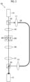
- Fig. 1 is a diagram showing an example of a configuration of an evaluation system 1 according to the embodiment of the disclosed technology.
- the evaluation system 1 includes an imaging apparatus 10, an image processing apparatus 20, and an evaluation apparatus 30.
- the imaging apparatus 10 captures a hologram in which a plurality of granules are contained within an imaging visual field.
- the imaging apparatus 10 captures the hologram of a plurality of spheres 300, which are aggregates of cells flowing inside a flow cell 200.
- the flow cell 200 is constituted by a member having a light-transmitting property, and forms a flow passage through which the sphere 300 flows.
- a flow passage cross section of the flow cell 200 has a quadrangular shape, a width dimension M is, for example, about 10 mm, and a depth dimension L is, for example, about 3 mm. That is, an area of the flow passage cross section of the flow cell 200 is sufficiently larger than a size of the sphere 300 (for example, about 100 ⁇ m to 500 ⁇ m).
- a shape and a size of the flow passage cross section of the flow cell 200 are not limited to those described above, and can be changed as appropriate.
- an optical axis direction of the imaging apparatus 10 is a z direction
- a flow direction of the sphere 300 is a y direction
- a width direction of the flow cell 200 is an x direction
- a plane orthogonal to the z direction is an xy plane.
- the imaging apparatus 10 be installed such that the entire flow cell 200 in the width direction (x direction) is contained within the imaging visual field when all of the plurality of spheres 300 are examined. Therefore, the plurality of spheres 300 flowing in the flow cell 200 are contained within the imaging visual field of the imaging apparatus 10.
- the imaging apparatus 10 may continuously image the plurality of spheres 300 flowing inside the flow cell 200. As a result, all of the spheres 300 in culture that sequentially flow inside the flow cell 200 can be an imaging target.
- the imaging apparatus 10 may be, for example, a complementary metal oxide semiconductor (CMOS) camera.
- CMOS complementary metal oxide semiconductor
- Fig. 2 is a diagram showing an example of a configuration of a hologram optical system 100 that acquires the hologram of the sphere by using known digital holography technology.
- the hologram optical system 100 includes an imaging apparatus 10.
- the digital holography technology is technology for imaging an image generated by interference between object light transmitted through or reflected by an object and reference light, which is coherent to the object light, by an image sensor, performing numerical calculation based on light propagation on the image obtained by imaging, and restoring a wave surface of light wave from the object.
- the digital holography technology it is possible to acquire three-dimensional information of the object without quantifying phase distribution of the object or mechanically moving a focal position.
- the hologram optical system 100 includes a laser light source 101, beam splitters 102 and 108, collimating lenses 103, 110, and 111, an objective lens 105, an imaging lens 107, and the imaging apparatus 10.
- the flow cell 200 in which the sphere 300, which is the imaging target, flows is disposed between the collimating lens 103 and the objective lens 105.
- a HeNe laser having a wavelength of 632.8 nm can be used as the laser light source 101.
- a laser beam emitted from the laser light source 101 is divided into two laser beams by the beam splitter 102.
- One of the two laser beams is the object light and the other is the reference light.
- the object light is converted parallel light by the collimating lens 103, and then is emitted to the sphere 300 flowing inside the flow cell 200.
- the image of the object light transmitted through the sphere 300 is expanded by the objective lens 105.
- the object light transmitted through the objective lens 105 is converted into the parallel light again by the imaging lens 107, and then is imaged on an imaging surface of the imaging apparatus 10 via the beam splitter 108.
- the reference light is incident on an optical fiber 109 via the collimating lens 111 and is guided to the front of the collimating lens 110 by the optical fiber 109.
- the reference light emitted from the optical fiber 109 is converted into the parallel light by the collimating lens 110, and is incident on the imaging surface of the imaging apparatus 10 via the beam splitter 108.
- the hologram generated by the interference between the object light and the reference light is recorded by the imaging apparatus 10.
- an off-axial optical system may be configured in which the optical axis directions of the object light and the reference light incident on the imaging surface of the imaging apparatus 10 are different from each other.
- the hologram of the sphere 300 imaged by the imaging apparatus 10 is stored in an image memory (not shown) provided in the imaging apparatus 10.
- the hologram of the sphere 300 stored in the image memory is supplied to the image processing apparatus 20.
- the optical axis direction of the imaging apparatus 10 is an optical axis direction of the imaging system, and coincides with a direction in which the objective lens 105, the imaging lens 107, the beam splitter 108, and the imaging apparatus 10 are arranged.
- Fig. 3 is a functional block diagram showing a functional configuration of the image processing apparatus 20.
- the image processing apparatus 20 performs the image processing on the hologram imaged by the imaging apparatus 10.
- the image processing apparatus 20 includes an acquisition unit 21, a phase difference image generation unit 22, a specifying unit 23, and an extraction unit 27.
- the phase difference image generation unit 22 is an example of a generation unit in the disclosed technology.
- the specifying unit 23 includes an addition average image generation unit 24, an inscribed circle derivation unit 25, and an expansion processing unit 26.
- the acquisition unit 21 acquires the hologram in which the plurality of spheres are contained within the imaging visual field, which is imaged by the imaging apparatus 10.
- the phase difference image generation unit 22 generates phase difference images at positions z different from each other in the optical axis direction (z direction) of the imaging apparatus 10 from the hologram acquired by the acquisition unit 21. Note that the details of the phase difference image will be described below.
- the phase difference image generation unit 22 generates the phase difference image by, for example, performing each of the following processing.
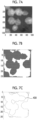
- the phase difference image generation unit 22 performs a two-dimensional Fourier transform on the hologram of the plurality of spheres shown in Fig. 4A acquired by the imaging apparatus 10.
- Fig. 4B is an example of a Fourier transform image of the sphere obtained by this processing.
- Fig. 4B shows an image based on direct light, the object light, and conjugation light.
- the phase difference image generation unit 22 specifies the position of the object light by specifying an amount of deviation of the object light with respect to the direct light in the Fourier transform image, and extracts a complex amplitude component of only the object light by frequency filtering processing.
- the phase difference image generation unit 22 applies, for example, an angular spectrum method to restore the image showing the phase of the sphere at any spatial position. Specifically, the phase difference image generation unit 22 obtains an angular spectrum U (f x , f y ; 0) of the Fourier transform image of a wave surface u (x, y; 0) captured by an image sensor surface of the imaging apparatus 10. Next, as described shown in Expression (1), the phase difference image generation unit 22 reproduces the wave surface at any position z in the optical axis direction (z direction) of the imaging apparatus 10 by multiplying the angular spectrum U (f x , f y ; 0) by a transfer function H (f x , f y ; z).
- the transfer function H (f x , f y ; z) is a frequency response function (Fourier transform of an impulse response function (Green's function)).
- the phase difference image generation unit 22 derives a solution u (x, y; z) at the position z by performing an inverse Fourier transform on the wave surface U (f x , f y ; z) at the position z in the optical axis direction (z direction) of the imaging apparatus 10.
- the phase difference image generation unit 22 generates the phase difference image by deriving a phase ⁇ for u (x, y; z) as shown in Expression (3).
- Fig. 4C is an example of the phase difference image before unwrapping of the sphere obtained by the processing described above.
- ⁇ arctan Im u Re u
- the phase difference image generation unit 22 may generate amplitude images at the positions z different from each other in the optical axis direction by deriving amplitude a for u (x, y; z).
- Fig. 4D is an example of the amplitude images of the plurality of spheres.
- phase of the sphere before unwrapping shown in Fig. 4C is convoluted to a value of 0 to 2 ⁇ . Therefore, for example, by applying a phase connection (unwrapping) method such as unweighted least squares or Flynn's algorithm and joining the portions of 2 ⁇ or more, a final phase difference image of the sphere as shown in Fig. 4E can be obtained. Note that many unwrapping methods have been proposed, and an appropriate method that does not cause phase inconsistency need only be appropriately selected.
- the phase difference image generation unit 22 generates the phase difference images at the positions z different from each other in the optical axis direction (z direction) of the imaging apparatus 10 by performing the processing described above.
- a pitch width of the positions z in the optical axis direction (z direction) of the imaging apparatus 10 may be, for example, about 1 ⁇ m.
- Fig. 5 is a diagram showing a concept of a phase difference image Ir.
- a lower part of Fig. 5 shows a three-dimensional display of a phase difference amount in each pixel k of the phase difference image Ir.
- the upper part of Fig. 5 shows the phase difference amount in each pixel k of the phase difference image Ir on a plane by gray scale.
- phase difference amount ⁇ in the phase difference image I P is expressed by Expression (5) in a case in which a phase of a background (region in which the spheres are not present), which is present in the same focal plane of the phase difference image I P is defined as ⁇ B , and a phase of a region in which the spheres are present is defined as ⁇ S .
- phase in the present specification is a phase of electric field amplitude in a case in which light is regarded as an electromagnetic wave, and is used in more general meaning.
- a phase difference amount ⁇ k in each pixel k of the phase difference image I P can be expressed by Expression (6).
- n k is a refractive index of the sphere at a portion corresponding to each pixel k of the phase difference image Ir
- d k is a thickness of the sphere at a portion corresponding to each pixel k of the phase difference image I P
- ⁇ is a wavelength of the object light in the hologram optical system.
- the phase difference image of the sphere is an image showing distribution of optical path lengths of the object light transmitted through the sphere. Since the optical path length in the sphere corresponds to the product of the refractive index of the sphere and the thickness of the sphere, the phase difference image of the sphere includes information on the refractive index and thickness (shape) of the sphere as shown in Expression (6).
- the specifying unit 23 specifies a range (region) in the xy plane in which an individual sphere extends in the phase difference image in which the plurality of spheres including the spheres in the state of overlapping with other spheres in the direction of the xy plane is captured.
- the specifying unit 23 generates an averaged image obtained by averaging at least some of the phase difference images for each position z in the optical axis direction (z direction) of the imaging apparatus 10, and specifies a plurality of image ranges in the direction of the xy plane corresponding to the plurality of spheres in this averaged image.
- the function of the specifying unit 23 will be described below in more detail.
- the specifying unit 23 includes the addition average image generation unit 24, the inscribed circle derivation unit 25, and the expansion processing unit 26.
- the addition average image generation unit 24 generates, as the averaged image described above, an addition average image obtained by adding and averaging (additive averaging) the phase difference images at the positions z different from each other in the optical axis direction (z direction) of the imaging apparatus 10.
- Fig. 6 is a diagram showing an example of the phase difference images generated by the phase difference image generation unit 22 at the positions z different from each other in the optical axis direction (z direction) of the imaging apparatus 10.
- phase difference image in which the position z in the optical axis direction (z direction) of the imaging apparatus 10 is changed from -5 ⁇ m to 5 ⁇ m by 1 ⁇ m steps is shown, but the pitch width of the position z and the range of the position z in the phase difference image generated by the phase difference image generation unit 22 are not limited to this example.
- the addition average image generation unit 24 generates an addition average image obtained by adding and averaging the phase difference images at the positions z different from each other in the optical axis direction (z direction) of the imaging apparatus 10 as shown in Fig. 6 .
- the sharpness of the outer edge of each sphere differs depending on the positions z in the optical axis direction (z direction) of the imaging apparatus 10 as shown in Fig. 6 . Therefore, in a case in which only one phase difference image at the specific position z in the optical axis direction (z direction) of the imaging apparatus 10 is used in a case in which the specifying unit 23 specifies the region of the sphere, the specific accuracy of the region of the sphere may be reduced.
- the addition average image generation unit 24 may generate the addition average image by using some of a plurality of the phase difference images at the positions z different from each other in the optical axis direction (z direction) of the imaging apparatus 10, which are generated by the phase difference image generation unit 22, or may generate the addition average image by using all of the phase difference images.
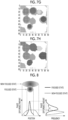
- the inscribed circle derivation unit 25 derives a plurality of inscribed circles inscribed in an outline with each point at which a distance from the outline corresponding to the outer edge of the sphere in the addition average image is longer than those of other surrounding points as a center. Specifically, the inscribed circle derivation unit 25 derives the inscribed circle by, for example, performing the following processing.
- the inscribed circle derivation unit 25 performs binarization processing on the addition average image shown in Fig. 7A generated by the addition average image generation unit 24.
- Fig. 7B is a diagram showing an example of the image after the binarization processing.
- Fig. 7C is a diagram showing an example of an outline 400 extracted from the image after the binarization processing.
- the inscribed circle derivation unit 25 uses a distance function ⁇ (x, y) to extract a plurality of points at which the distance from the extracted outline 400 is longer than those of other surrounding points.
- the distance function ⁇ (x, y) is obtained by deriving the distance between a coordinate (x, y) and the point on the outline 400 at the position at which the distance from the coordinate (x, y) of any pixel in the image is the shortest, for each pixel of an inner region of the outline 400.
- Fig. 7D is an image of the distance function ⁇ (x, y).
- Fig. 7E is a diagram showing an example of a plurality of points C at which the distance from the outline 400 is longer than those of other surrounding points, which is extracted based on the distance function ⁇ (x, y).
- Fig. 7F is a diagram showing an example of a derived plurality of inscribed circles 401.
- the expansion processing unit 26 performs expansion processing on each of the inscribed circles 401 derived by the inscribed circle derivation unit 25. Specifically, the expansion processing unit 26 performs, for example, the following processing. First, the expansion processing unit 26 fills each of the inscribed circles 401 before the expansion processing as shown in Fig. 7G . Subsequently, in a case in which there is an unfilled pixel among eight pixels adjacent to each other, which have been already filled, the expansion processing unit 26 fills the unfilled pixel. By repeating this processing by the expansion processing unit 26, a filled region is expanded. The expansion processing unit 26 performs the above expansion processing in parallel with all of the inscribed circles 401 derived by the inscribed circle derivation unit 25.
- the expansion processing unit 26 terminates the expansion processing in the pixel in a case in which the filled regions derived from the inscribed circles 401 different from each other collide with each other and in a case in which the filled region reaches the outline 400.
- Fig. 7H is a diagram showing an example of an image after the expansion processing. Each of the filled regions after the expansion processing is the image range corresponding to each of the plurality of spheres.
- the specifying unit 23 including the addition average image generation unit 24, the inscribed circle derivation unit 25, and the expansion processing unit 26 the range (region) in the xy plane in which the individual sphere extends in the phase difference image in which the plurality of spheres including the spheres in the state of overlapping with other spheres in the direction of the xy plane is captured is specified.
- the extraction unit 27 extracts, for each of the image ranges corresponding to each of the spheres specified in the specifying unit 23, the phase difference image at the center position of the sphere in the optical axis direction (z direction) from the phase difference images for each position z in the optical axis direction (z direction) of the imaging apparatus 10 shown in Fig. 6 .
- phase difference image in which the sphere is not focused From the phase difference image in which the sphere is not focused, accurate information that coincides with an actual condition of the sphere cannot be obtained due to the effect of spreading due to diffraction.
- the cell is evaluated by using a phase difference image
- the phase difference image in which the sphere, which is an evaluation target it is preferable to use the phase difference image in which the sphere, which is an evaluation target, is focused.
- the sphere is focused means obtaining the phase difference image sliced near the center of the spherical sphere. More accurate evaluation can be performed by evaluating the sphere by using the phase difference image in which the sphere is focused.
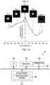
- a graph on the left of Fig. 8 shows an example of a relationship between the position in a direction of a plane (x direction or y direction) and the phase difference amount in the phase difference image of the sphere, in which the solid line corresponds to a state in which the sphere is not focused and the dotted line corresponds to a state in which the sphere is focused.
- the solid line corresponds to a state in which the sphere is not focused
- the dotted line corresponds to a state in which the sphere is focused.
- a steep peak appears at the specific position in the phase difference image.
- the peak is lower and gentler than a case in which the sphere is focused.
- a graph on the right of Fig. 8 shows an example of the histogram of the phase difference amount in the phase difference image of the sphere, in which the solid line corresponds to a state in which the sphere is focused and the dotted line corresponds to a state in which the sphere is not focused.
- a curve width w (variation of the phase difference amounts) is relatively large, and in a case in which the sphere is not focused, the curve width w (variation of the phase difference amounts) is relatively small.
- the curve width w (variation of the phase difference amounts) in the histogram of the phase difference amount is obtained, and the phase difference image having the maximum width w among the obtained widths w is extracted as the phase difference image in which the sphere is focused, so that focusing can be realized.
- the phase difference image having the maximum width w that is, the phase difference image having the maximum variation of the phase difference amounts corresponds to the phase difference image at the center position of the sphere in the optical axis direction (z direction).
- the extraction unit 27 may derive a difference between the maximum value and the minimum value of the phase difference amount in the specified image range as the variation of the phase difference amounts in the image range.
- the extraction unit 27 may derive a standard deviation of the phase difference amount in the specified image range as the variation of the phase difference amounts in the image range.
- the extraction unit 27 extracts the image at the position z at which the variation of the phase difference amounts is maximum for each of the specified image ranges.
- Fig. 9 is a graph showing an example of a relationship between the focal position (slice position) and the variation of the phase difference amounts in the phase difference image of the sphere.
- Fig. 9 shows the phase difference images in which the focal positions of the spheres correspond to-400 ⁇ m, -200 ⁇ m, 0 ⁇ m, +200 ⁇ m, and +400 ⁇ m together with the graph.
- the focal position at which the variation of the phase difference amounts is maximum is set to 0 ⁇ m.
- the phase difference image corresponding to the focal position of 0 ⁇ m at which the variation of the phase difference amounts is maximum is extracted as the focused phase difference image.
- the outline of the sphere is the clearest in the phase difference image corresponding to the focal position 0 ⁇ m at which the variation of the phase difference amounts is maximum.
- Fig. 10 is an example of a hardware configuration of the image processing apparatus 20.
- the image processing apparatus 20 includes a central processing unit (CPU) 501, a main memory 502 as a transitory storage region, a non-volatile auxiliary memory 503, and a communication interface 504 that performs communication with other apparatuses including the evaluation apparatus 30 and the imaging apparatus 10.
- the CPU 501, the main memory 502, the auxiliary memory 503, and the communication interface 504 are each connected to a bus 505.
- the auxiliary memory 503 stores an image processing program 506 that causes the CPU 501 to function as the acquisition unit 21, the phase difference image generation unit 22, the specifying unit 23, and the extraction unit 27.
- the CPU 501 reads out the image processing program 506 from the auxiliary memory 503, develops the readout image processing program 506 in the main memory 502, and sequentially executes the image processing described in the image processing program 506 based on an instruction from an outside supplied via the communication interface 504.
- Fig. 11 is a flowchart showing an example of a flow of the image processing described in the image processing program 506.
- step S1 the CPU 501 functions as the acquisition unit 21 and acquires the hologram in which the plurality of spheres are contained within the imaging visual field, which is imaged by the imaging apparatus 10.
- step S2 the CPU 501 functions as the phase difference image generation unit 22 and generates the phase difference images at the positions z different from each other in the optical axis direction (z direction) of the imaging apparatus 10 from the hologram.
- step S3 the CPU 501 functions as the specifying unit 23 (addition average image generation unit 24) and generates the addition average image (see Fig. 6 ) obtained by adding and averaging the phase difference images at the positions z different from each other in the optical axis direction (z direction) of the imaging apparatus 10.
- step S4 the CPU 501 functions as the specifying unit 23 (inscribed circle derivation unit 25) and performs the binarization processing on the addition average image (see Fig. 7B ).
- step S5 the CPU 501 functions as the specifying unit 23 (inscribed circle derivation unit 25) and extracts the outline 400 corresponding to the outer edge of the sphere from the image after the binarization processing (see Fig. 7C ).
- step S6 the CPU 501 functions as the specifying unit 23 (inscribed circle derivation unit 25) and specifies the plurality of points C at which the distance from the extracted outline 400 is longer than those of other surrounding points by using the distance function ⁇ (x, y) (see Fig. 7E ).
- step S7 the CPU 501 functions as the specifying unit 23 (inscribed circle derivation unit 25) and derives the plurality of inscribed circles 401 inscribed in the outline 400 as each of the extracted plurality of points C as a center (see Fig. 7F ).
- step S8 the CPU 501 functions as the specifying unit 23 (expansion processing unit 26) and performs the expansion processing on each of the inscribed circles 401.
- each of the plurality of image ranges in the direction of the plane (xy plane) intersecting the optical axis direction (z direction) of the imaging apparatus 10 corresponding to each of the plurality of spheres is specified. That is, the region in the direction of the xy plane of each of the plurality of spheres which are present with an overlapping portion with other spheres is specified.
- step S9 the CPU 501 functions as the extraction unit 27 and derives the variation of the phase difference amounts for each of the image ranges corresponding to each of the spheres specified in step S8.
- the CPU 501 may derive the difference between the maximum value and the minimum value of the phase difference amount in the specified image range as the variation of the phase difference amounts in the image range.
- the CPU 501 may derive the standard deviation of the phase difference amount in the specified image range as the variation of the phase difference amounts in the image range.
- the CPU 501 performs the processing described above of deriving the variation of the phase difference amounts for the phase difference images for the positions z in the optical axis direction (z direction) of the imaging apparatus 10 generated in step S2.
- step S10 the CPU 501 functions as the extraction unit 27 and extracts the image at the position z in the optical axis direction at which the variation of the phase difference amounts is maximum for each of the image ranges corresponding to each of the spheres specified in step S8.
- the evaluation apparatus 30 evaluates the sphere by using the phase difference image extracted by the extraction unit 27 of the image processing apparatus 20, and outputs an evaluation result.
- Fig. 12 is a functional block diagram showing an example of a functional configuration of the evaluation apparatus 30.
- the evaluation apparatus 30 includes an acquisition unit 31, a shape index value derivation unit 32, a phase difference amount sum derivation unit 33, and a determination unit 34.
- the acquisition unit 31 acquires the phase difference image extracted by the extraction unit 27 of the image processing apparatus 20. That is, the acquisition unit 31 acquires the phase difference image at the center position in the optical axis direction (z direction) of the imaging apparatus 10 for each of the plurality of spheres.
- the shape index value derivation unit 32 derives a shape index value of the sphere included in the phase difference image acquired by the acquisition unit 31.
- the shape index value of the sphere for example, volume, a cross section area, a particle diameter, a circumference, and the like of the sphere can be used.
- the particle diameter and the circumference of the sphere can be obtained directly from the phase difference image at the center position of the sphere in the optical axis direction.
- the cross section area of the sphere can be derived, for example, as a cross section area of a circle of which a diameter is the particle diameter of the sphere.
- the volume of the sphere can be derived, for example, as the volume of the sphere of which a diameter is the particle diameter of the sphere.
- the phase difference amount sum derivation unit 33 derives a phase difference amount sum ⁇ A , which is a value obtained by integrating the phase difference amounts of a plurality of pixels constituting the phase difference image.
- the phase difference amount sum ⁇ A is expressed by Expression (7). Note that s is the area of each pixel k of the phase difference image, and v k is the volume of the sphere at the portion corresponding to each pixel k of the phase difference image. As shown in Expression (7), the phase difference amount sum ⁇ A corresponds to the value obtained by integrating the phase difference amounts ⁇ k for the pixels of the phase difference image of the sphere for all of the pixels k.
- d k indicates a thickness of a sphere portion projected on the pixel k
- n k indicates a refractive index difference between a background culture solution and an inside of the sphere.
- the determination unit 34 compares the correlation between a reference correlation trend line showing a reference of the correlation between the phase difference amount sum ⁇ A and the shape index value of the sphere and the correlation between the phase difference amount sum ⁇ A and the shape index value for the sphere, which is a determination target, and determines the state of the sphere, which is the determination target, in response to a degree of the deviation of the correlation for the sphere, which is the determination target, from the reference correlation trend line.
- the reference correlation trend line can be acquired in advance and used.
- the determination unit 34 may determine that at least one of the viability, the density, or the homogeneity of the cell included in the sphere, or the outer shape of the sphere, which is the determination target, is abnormal.
- Fig. 13 is an example of a hardware configuration of the evaluation apparatus 30.
- the evaluation apparatus 30 includes a CPU 601, a main memory 602 as a transitory storage region, a non-volatile auxiliary memory 603, and a communication interface 604 that performs communication with other apparatuses including the image processing apparatus 20.
- the CPU 601, the main memory 602, the auxiliary memory 603, and the communication interface 604 are each connected to a bus 605.
- the auxiliary memory 603 stores an evaluation program 606 that causes the CPU 601 to function as the acquisition unit 31, the shape index value derivation unit 32, the phase difference amount sum derivation unit 33, and the determination unit 34.
- the CPU 601 reads out the evaluation program 606 from the auxiliary memory 603, develops the readout evaluation program 606 in the main memory 602, and sequentially executes the evaluation processing described in the evaluation program 606 based on an instruction from an outside supplied via the communication interface 604. Note that in the present embodiment, a case is described in which the evaluation apparatus 30 and the image processing apparatus 20 are configured by separate computers, but the evaluation apparatus 30 and the image processing apparatus 20 can also be configured by a common computer.
- Fig. 14 is a flowchart showing an example of a flow of the evaluation processing described in the evaluation program 606.
- step S11 the CPU 601 functions as the acquisition unit 31 and acquires the phase difference image extracted by the extraction unit 27 of the image processing apparatus 20.
- step S12 the CPU 601 functions as the shape index value derivation unit 32 and derives the shape index value of the sphere included in the phase difference image acquired in step S11.
- the shape index value of the sphere for example, the volume, the cross section area, the particle diameter, the circumference, and the like of the sphere can be used.
- step S13 the CPU 601 functions as the phase difference amount sum derivation unit 33 and derives the phase difference amount sum ⁇ A for the phase difference image acquired in step S11.
- step S14 the CPU 601 functions as the determination unit 34, compares the correlation between the reference correlation trend line showing the reference of the correlation between the phase difference amount sum ⁇ A and the shape index value of the sphere and the correlation between the phase difference amount sum ⁇ A and the shape index value for the sphere, which is a determination target, determines the state of the sphere, which is the determination target, in response to the degree of the deviation of the correlation for the sphere, which is the determination target, from the reference correlation trend line, and outputs a determination result.
- the reference correlation trend line can be stored in advance in the auxiliary memory 603 and used.
- the determination unit 34 may determine that at least one of the viability, the density, or the homogeneity of the cell included in the sphere, or the outer shape of the sphere, which is the determination target, is abnormal.
- Fig. 15 is a graph showing an example of a correlation characteristic between the volume of the sphere and the phase difference amount sum ⁇ A . As shown in Fig. 15 , it is confirmed that the phase difference amount sum ⁇ A and the volume of the sphere are in a proportional relationship.
- a reference correlation trend line Ls showing the reference of the correlation between the volume of the sphere and the phase difference amount sum ⁇ A is shown together with the plot. The regression line derived from each plot shown in Fig. 15 is applied as the reference correlation trend line Ls.
- Fig. 15 shows the phase difference images of the spheres corresponding to plots a1 and a2 present on the reference correlation trend line Ls and the phase difference images of the spheres corresponding to plots a3, a4, and a5 present at positions deviating from the reference correlation trend line Ls.
- the phase difference images having uniform brightness are obtained over the entire sphere. This result indicates that the plurality of cells constituting the sphere are homogeneous, and that the density of cells in the sphere is uniform.
- the phase difference images having the brightness at the central portion, which is decreased as compared with that in other portions are obtained.
- This result indicates that the plurality of cells constituting the sphere are not homogeneous, and that the density of cells in the sphere is not uniform.
- the phase difference image in which the unevenness of the outline of the sphere is remarkable is obtained. This result indicates that the cells constituting the sphere are abnormal.
- the state of the sphere can be determined by using the correlation between the phase difference amount sum ⁇ A and the volume, which is an example of the shape index value of the sphere.
- each sphere in response to the degree of the deviation of the reference correlation trend line Ls from the plots for the sphere, which is the determination target, plotted on a graph on which one axis is the volume of the sphere and the other axis is the phase difference amount sum ⁇ A . Therefore, for example, for the sphere of which a minus width of the phase difference amount sum ⁇ A from the reference correlation trend line Ls is equal to or greater than a threshold value, it can be determined that at least one of the density, the homogeneity, or the outer shape of the sphere of the cell included in the sphere is abnormal.
- the volume of the sphere is used as the shape index value of the sphere, but instead of the volume, the cross section area, the particle diameter, or the circumference of the sphere can be used. Regardless of which of these shape index values is used, it is possible to determine the state of the sphere by using the correlation with the phase difference amount sum ⁇ A .
- Fig. 16 is a functional block diagram showing another example of the functional configuration of the evaluation apparatus 30.
- the evaluation apparatus 30 includes the acquisition unit 31, a phase difference amount density derivation unit 35, and the determination unit 34.
- the evaluation apparatus 30 derives a phase difference amount density D P obtained by dividing the phase difference amount sum ⁇ A by the volume of the sphere, and determines the state of the sphere based on the derived phase difference amount density D P .
- the phase difference amount density D P is expressed by Expression (8). Note that V is the volume of the sphere. As shown in Expression (8), the phase difference amount density D P corresponds to the phase difference amount sum ⁇ A divided by the volume V of the sphere. Due to homeostasis, healthy cells are considered to maintain a fixed value of internal refractive index, which is different from the refractive index of a medium. On the other hand, it is considered that dead cells lose homeostasis and the internal refractive index is substantially the same as the refractive index of the medium. Therefore, it is considered that the phase difference amount density D P can be used as an index indicating the state of the cell.
- phase difference amount density Dr acquired for the sphere which is the determination target
- the phase difference amount density D P is less than the threshold value
- the state of the sphere is abnormal. Note that since 2 ⁇ / ⁇ can be treated as a fixed value, the multiplication of 2 ⁇ / ⁇ may be omitted in a case of deriving the phase difference amount density Dr.
- the phase difference amount density is the refractive index difference of the volume-averaged sphere normalized by a wavelength length.
- V is obtained by calculating an equivalent sphere diameter from a cross section image of a phase image of the sphere. It is also possible to obtain an ellipsoidal sphere more accurately.
- Fig. 17 is a flowchart showing another example of the flow of the evaluation processing described in the evaluation program 606 according to the present embodiment.
- step S21 the CPU 601 functions as the acquisition unit 31 and acquires the phase difference image extracted by the extraction unit 27 of the image processing apparatus 20.
- step S22 the CPU 601 functions as the phase difference amount density derivation unit 35 and derives the phase difference amount density D P for the phase difference image acquired in step S21.
- step S23 the CPU 601 functions as the determination unit 34, estimates the cell viability in the sphere based on a correlation line showing the correlation between the cell viability and the phase difference amount density D P , which is acquired in advance, and the phase difference amount density D P derived in step S22, and outputs the determination result.
- Fig. 18 is a graph showing an example of a correlation characteristic between cell viability and the phase difference amount density D P (lot average value).
- a procedure for measurement of the viability is as follows. The spheres housed in a centrifuge tube are subjected to centrifugation processing at 400 G for 3 minutes. The spheres precipitated at the bottom of the centrifuge tube are collected and decomposed into single cells by using TrypLE (registered trademark) Select, which is cell dissociation enzyme. By performing to dead cell staining processing with Trypan Blue on the decomposed cells and then counting the cells with a general commercially available cell counter (Countess (registered trademark)), the number of stained dead cells is counted. The cell viability is derived for each culture lot from the count number of dead cells.
- the correlation characteristic between the cell viability and the phase difference amount density D P (lot average value) is acquired. As shown in Fig. 18 , it is confirmed that the cell viability and the phase difference amount density Dr are in a proportional relationship.
- the cell viability can be estimated from the phase difference amount density D P .
- the cell viability can be grasped without performing processing involving cell destruction, such as the centrifugation processing and the staining processing (that is, non-destructively).
- the evaluation apparatus 30 outputs the cell viability in the culture lot estimated from the correlation line showing the correlation between the cell viability and the phase difference amount density D P and the average value of the phase difference amount density D P acquired for the sphere belonging to the culture lot, which is the determination target, as the determination result.
- phase difference image generation unit 22 As described above, with the evaluation system 1 according to the embodiment of the disclosed technology, it is assumed that in the phase difference image generated by the phase difference image generation unit 22, at least some of the plurality of spheres partially overlap with each other in the direction of the plane (xy plane) intersecting the optical axis direction (z direction) of the imaging apparatus 10. In order to use the phase difference image for evaluation of the individual sphere, it is necessary to separate the plurality of spheres in the state of partially overlapping with other in the phase difference image and recognize the spheres as separate spheres.
- the phase difference image generation unit 22 generates the phase difference images at the positions different from each other in the optical axis direction (z direction) of the imaging apparatus 10 from the hologram imaged by the imaging apparatus 10, the specifying unit 23 specifies the plurality of image ranges in the direction of the xy plane corresponding to the plurality of spheres in the addition average image obtained by adding and averaging the phase difference images, and the extraction unit 27 extracts the phase difference image at the center position in the optical axis direction (z direction) of the corresponding sphere in each of the specified image ranges.
- the specifying unit 23 specifies the range (region) in the xy plane in which the individual sphere extends, and the extraction unit 27 extracts the appropriately focused phase difference image for an extend range (region) of each sphere. Therefore, with the image processing apparatus 20, it is possible to appropriately perform the evaluation the state of each sphere.
- each of the plurality of spheres is evaluated based on the hologram obtained by imaging the plurality of spheres contained within the imaging visual field, so that it is possible to significantly shorten the processing time as compared with the evaluation method in the related art using flow cytometry. That is, with the evaluation system 1, a large amount of the spheres can be evaluated non-destructively and quickly.
- the specifying unit 23 uses the averaged image and the addition average image used in a case of specifying the image range corresponding to each of the spheres, but a geometric mean image obtained by synergistically averaging at least some of the phase difference images may be used as the averaged image, or a weighted averaged image obtained by weighted averaging at least some of the phase difference images may be used as the averaged image.
Claims (8)
- Appareil (20) de traitement d'image, comprenant :une unité (21) d'acquisition configurée pour acquérir un hologramme obtenu par l'imagerie d'une pluralité de granules s'écoulant dans un passage (200) d'écoulement ;une unité (22) de génération configurée pour générer, à partir de l'hologramme, des images de différence de phase à différentes positions dans une direction d'axe optique dans laquelle l'hologramme est capturé ;une unité (23) de spécification configurée pour spécifier une pluralité de régions d'image dans un plan venant en intersection avec la direction d'axe optique, chaque région d'image incluant un granule respectif, dans une image moyennée obtenue en faisant la moyenne d'au moins certaines des images de différence de phase ; etune unité (27) d'extraction configurée pour extraire une image de différence de phase sur la base d'une position centrale, dans la direction d'axe optique, d'un granule correspondant pour chaque région d'image de la pluralité de régions d'image.
- Appareil de traitement d'image selon la revendication 1,
dans lequel l'unité (23) de spécification inclut :une unité (24) de génération d'image moyenne configurée pour générer l'image moyennée en faisant la moyenne d'au moins certaines des images de différence de phase ;une unité (25) de dérivation de cercle inscrit configurée pour dériver une pluralité de cercles inscrits (401) inscrits dans un contour (400) correspondant à un bord externe de la pluralité de granules sur l'image moyennée, le centre de chacun de la pluralité de cercles inscrits (401) correspondant à un point respectif auquel une distance par rapport au contour (400) est supérieure à celles des autres points environnants ; etune unité (26) de traitement d'expansion configurée pour effectuer un traitement d'expansion en parallèle sur chacun des cercles inscrits (401), afin d'étendre une région respective du cercle inscrit (401) jusqu'à ce que la région respective entre en collision avec une région d'un cercle inscrit (401) différent ou que la région respective atteigne le contour (400) correspondant au bord externe de la pluralité de granules. - Appareil de traitement d'image selon la revendication 1 ou la revendication 2,
dans lequel l'unité d'extraction est configurée pour extraire, en tant qu'image de différence de phase au niveau de la position centrale dans la direction d'axe optique du granule correspondant, une image de différence de phase présentant une variation maximale de quantités de différence de phase entre des pixels parmi les images de différence de phase. - Appareil (20) de traitement d'image selon l'une quelconque des revendications 1 à 3,
dans lequel chaque granule est un agrégat d'une pluralité de cellules. - Système (1) d'évaluation comprenant :un passage (200) d'écoulement à travers lequel s'écoulent une pluralité de granules ;un appareil (10) d'imagerie configuré pour capturer un hologramme par la capture d'images de la pluralité de granules ;un appareil (20) de traitement d'image configuré pour mettre en oeuvre un traitement d'image sur l'hologramme ; etun appareil (30) d'évaluation configuré pour délivrer un résultat d'évaluation d'un état d'un granule individuel pour chaque granule de la pluralité de granules sur la base du traitement d'image,dans lequel l'appareil (20) de traitement d'image inclutune unité (21) d'acquisition configurée pour acquérir l'hologramme,une unité (22) de génération configurée pour générer, à partir de l'hologramme, des images de différence de phase à différentes positions dans une direction d'axe optique dans laquelle l'hologramme est capturé,une unité (23) de spécification configurée pour spécifier une pluralité de régions d'image dans un plan venant en intersection avec la direction d'axe optique, chaque région d'image incluant un granule respectif, dans une image moyennée obtenue en faisant la moyenne d'au moins certaines des images de différence de phase, etune unité (27) d'extraction configurée pour extraire une image de différence de phase sur la base d'une position centrale, dans la direction d'axe optique, d'un granule correspondant pour chaque région d'image de la pluralité de régions d'image, etdans lequel l'appareil (30) d'évaluation est configuré pour dériver le résultat d'évaluation en utilisant l'image de différence de phase extraite par l'unité (27) d'extraction.
- Système (1) d'évaluation selon la revendication 5, comprenant en outre :
dans lequel l'appareil (10) d'imagerie est installé de telle sorte qu'une région du passage (200) d'écoulement dans une direction de largeur du passage (200) d'écoulement est contenue dans un champ visuel d'imagerie de l'appareil (10) d'imagerie. - Support d'enregistrement lisible par ordinateur stockant un programme de traitement d'image amenant un ordinateur à exécuter un procédé comprenant :l'acquisition d'un hologramme obtenu par l'imagerie d'une pluralité de granules s'écoulant dans un passage (200) d'écoulement ;la génération, à partir de l'hologramme, d'images de différence de phase à différentes positions dans une direction d'axe optique dans laquelle l'hologramme est capturé ;la spécification d'une pluralité de régions d'image dans un plan venant en intersection avec la direction d'axe optique, chaque région d'image incluant un granule respectif, dans une image moyennée obtenue en faisant la moyenne d'au moins certaines des images de différence de phase ; etl'extraction d'une image de différence de phase au niveau d'une position centrale dans la direction d'axe optique d'un granule correspondant pour chaque région d'image de la pluralité de régions d'image.
- Procédé de traitement d'image mis en oeuvre par ordinateur comprenant :l'acquisition d'un hologramme obtenu par l'imagerie d'une pluralité de granules s'écoulant dans un passage (200) d'écoulement ;la génération, à partir de l'hologramme, d'images de différence de phase à différentes positions dans une direction d'axe optique dans laquelle l'hologramme est capturé ;la spécification d'une pluralité de régions d'image dans un plan venant en intersection avec la direction d'axe optique, chaque région d'image correspondant à un granule respectif, dans une image moyennée obtenue en faisant la moyenne d'au moins certaines des images de différence de phase ; etl'extraction d'une image de différence de phase au niveau d'une position centrale dans la direction d'axe optique d'un granule correspondant pour chaque région d'image de la pluralité de régions d'image.
Applications Claiming Priority (2)
| Application Number | Priority Date | Filing Date | Title |
|---|---|---|---|
| JP2019122482 | 2019-06-28 | ||
| PCT/JP2020/020027 WO2020261826A1 (fr) | 2019-06-28 | 2020-05-21 | Dispositif de traitement d'image, système d'évaluation, programme de traitement d'image, et procédé de traitement d'image |
Publications (3)
| Publication Number | Publication Date |
|---|---|
| EP3992609A1 EP3992609A1 (fr) | 2022-05-04 |
| EP3992609A4 EP3992609A4 (fr) | 2022-08-10 |
| EP3992609B1 true EP3992609B1 (fr) | 2024-04-17 |
Family
ID=74061967
Family Applications (1)
| Application Number | Title | Priority Date | Filing Date |
|---|---|---|---|
| EP20833156.1A Active EP3992609B1 (fr) | 2019-06-28 | 2020-05-21 | Appareil de traitement d'images, système d'évaluation, support d'enregistrement et procédé de traitement d'images |
Country Status (4)
| Country | Link |
|---|---|
| US (1) | US11480920B2 (fr) |
| EP (1) | EP3992609B1 (fr) |
| JP (1) | JP7026853B2 (fr) |
| WO (1) | WO2020261826A1 (fr) |
Families Citing this family (2)
| Publication number | Priority date | Publication date | Assignee | Title |
|---|---|---|---|---|
| JPWO2022181024A1 (fr) * | 2021-02-26 | 2022-09-01 | ||
| CN117098987A (zh) * | 2021-04-09 | 2023-11-21 | 富士胶片株式会社 | 全息装置及细胞的评价方法 |
Family Cites Families (12)
| Publication number | Priority date | Publication date | Assignee | Title |
|---|---|---|---|---|
| US8885913B2 (en) * | 1999-01-25 | 2014-11-11 | Amnis Corporation | Detection of circulating tumor cells using imaging flow cytometry |
| JP2003156427A (ja) * | 2001-11-21 | 2003-05-30 | Mauntekku:Kk | 粒子形状解析方法および装置 |
| EP2602608B1 (fr) | 2011-12-07 | 2016-09-14 | Imec | Analyse et tri des cellules biologiques dans un écoulement |
| US8687253B2 (en) * | 2011-12-13 | 2014-04-01 | Canon Kabushiki Kaisha | Speckle noise reduction based on longitudinal shift of sample |
| EP2626686A1 (fr) | 2012-02-13 | 2013-08-14 | Ovizio Imaging Systems NV/SA | Cytomètre de flux avec microscope holographique numérique |
| US10670510B2 (en) | 2013-02-05 | 2020-06-02 | Massachusetts Institute Of Technology | 3-D holographic imaging continuous flow cytometry |
| FR3030749B1 (fr) * | 2014-12-19 | 2020-01-03 | Commissariat A L'energie Atomique Et Aux Energies Alternatives | Methode d'identification de particules biologiques par piles d'images holographiques defocalisees |
| JP2016133466A (ja) | 2015-01-21 | 2016-07-25 | ウシオ電機株式会社 | 水質検査システム |
| WO2018237239A1 (fr) * | 2017-06-23 | 2018-12-27 | Texas Tech University System | Procédé et dispositif pour le criblage holographique sans étiquette et à haut rendement et l'énumération de cellules tumorales dans le sang |
| CA3082097A1 (fr) * | 2017-11-14 | 2019-05-23 | miDiagnostics NV | Classification d'une population d'objets par apprentissage de dictionnaire convolutif avec des donnees de proportion de classe |
| EP3575773A1 (fr) * | 2018-05-28 | 2019-12-04 | Universität für Bodenkultur Wien | Procédé permettant de déterminer une distribution de particules tridimensionnelles dans un milieu |
| EP3803384A4 (fr) * | 2018-06-04 | 2021-08-11 | The Regents of University of California | Cytomètre de flux d'imagerie portable à apprentissage profond pour analyse sans marqueur d'échantillons d'eau |
-
2020
- 2020-05-21 WO PCT/JP2020/020027 patent/WO2020261826A1/fr active Application Filing
- 2020-05-21 EP EP20833156.1A patent/EP3992609B1/fr active Active
- 2020-05-21 JP JP2021527485A patent/JP7026853B2/ja active Active
-
2021
- 2021-11-30 US US17/537,590 patent/US11480920B2/en active Active
Non-Patent Citations (1)
| Title |
|---|
| DRIES VERCRUYSSE ET AL: "Three-part differential of unlabeled leukocytes with a compact lens-free imaging flow cytometer", LAB ON A CHIP, vol. 15, no. 4, 1 January 2015 (2015-01-01), UK, pages 1123 - 1132, XP055221009, ISSN: 1473-0197, DOI: 10.1039/C4LC01131G * |
Also Published As
| Publication number | Publication date |
|---|---|
| WO2020261826A1 (fr) | 2020-12-30 |
| JPWO2020261826A1 (fr) | 2020-12-30 |
| EP3992609A1 (fr) | 2022-05-04 |
| US20220083004A1 (en) | 2022-03-17 |
| JP7026853B2 (ja) | 2022-02-28 |
| US11480920B2 (en) | 2022-10-25 |
| EP3992609A4 (fr) | 2022-08-10 |
Similar Documents
| Publication | Publication Date | Title |
|---|---|---|
| US11893728B2 (en) | Method for determining a state of a sphere | |
| JP6559555B2 (ja) | 光計測方法および装置 | |
| US11480920B2 (en) | Image processing apparatus, evaluation system, image processing program, and image processing method | |
| CN108377658B (zh) | 数字全息术中的自动聚焦系统和方法 | |
| KR20180011762A (ko) | 입자 분석 방법 | |
| JP2023530078A (ja) | 媒質内の粒子の焦点距離を特定するための方法 | |
| Moon et al. | 3-D visualization and identification of biological microorganisms using partially temporal incoherent light in-line computational holographic imaging | |
| CN107110764A (zh) | 利用位置控制对透明样本进行分析的系统及相关联的方法 | |
| JP6867731B2 (ja) | 微粒子観察装置及び微粒子観察方法 | |
| Wu et al. | Direct particle depth displacement measurement in DHPTV using spatial correlation of focus metric curves | |
| CN108593528B (zh) | 基于激光干涉的非球形粗糙粒子形状和尺寸测量方法 | |
| CN108562522B (zh) | 一种粒子尺寸和折射率同时测量方法 | |
| May et al. | A Priori Information and Off-Axis Measurements in Terahertz Tomography | |
| Zhang et al. | A new method for determining the sampling volume and the number of particles within it for particle concentration identification in defocused interferometric particle imaging | |
| US11869181B2 (en) | Determination method | |
| CN113706567A (zh) | 一种结合血管形态特征的血流成像量化处理方法与装置 | |
| Varjo et al. | All-in-focus image reconstruction from in-line holograms of snowflakes | |
| US20210174506A1 (en) | Determination method | |
| Darakis et al. | Processing of digital holograms for size measurements of microparticles | |
| Dyomin et al. | Accuracy of Determination of Longitudinal Coordinates of Particles by Digital Holography | |
| US20230274441A1 (en) | Analysis method and analysis apparatus | |
| CN210155011U (zh) | 一种基于数字同轴全息测量液滴折射率的装置 | |
| KR102139477B1 (ko) | 매질 특성 차이를 이용한 영상 기반의 시료 분석 장치를 이용하여 시료를 측정하고 분석하는 방법 | |
| Will et al. | Algorithms for Weld Depth Measurement in Laser Welding of Copper with Scanning Optical Coherence Tomography. Micromachines 2022, 13, 2243 | |
| Li et al. | Accurate axial location for particles in digital in-line holography |
Legal Events
| Date | Code | Title | Description |
|---|---|---|---|
| STAA | Information on the status of an ep patent application or granted ep patent |
Free format text: STATUS: THE INTERNATIONAL PUBLICATION HAS BEEN MADE |
|
| PUAI | Public reference made under article 153(3) epc to a published international application that has entered the european phase |
Free format text: ORIGINAL CODE: 0009012 |
|
| STAA | Information on the status of an ep patent application or granted ep patent |
Free format text: STATUS: REQUEST FOR EXAMINATION WAS MADE |
|
| 17P | Request for examination filed |
Effective date: 20211201 |
|
| AK | Designated contracting states |
Kind code of ref document: A1 Designated state(s): AL AT BE BG CH CY CZ DE DK EE ES FI FR GB GR HR HU IE IS IT LI LT LU LV MC MK MT NL NO PL PT RO RS SE SI SK SM TR |
|
| REG | Reference to a national code |
Ref country code: DE Ref legal event code: R079 Ref document number: 602020029298 Country of ref document: DE Free format text: PREVIOUS MAIN CLASS: G01N0015140000 Ipc: C12M0001340000 Ref country code: DE Free format text: PREVIOUS MAIN CLASS: G01N0015140000 Ipc: C12M0001340000 |
|
| A4 | Supplementary search report drawn up and despatched |
Effective date: 20220712 |
|
| RIC1 | Information provided on ipc code assigned before grant |
Ipc: G06V 20/69 20220101ALI20220706BHEP Ipc: G06V 10/88 20220101ALI20220706BHEP Ipc: G06V 10/44 20220101ALI20220706BHEP Ipc: G06V 10/34 20220101ALI20220706BHEP Ipc: G06V 10/143 20220101ALI20220706BHEP Ipc: G03H 1/08 20060101ALI20220706BHEP Ipc: G03H 1/04 20060101ALI20220706BHEP Ipc: G03H 1/00 20060101ALI20220706BHEP Ipc: G01N 21/17 20060101ALI20220706BHEP Ipc: G01N 15/14 20060101ALI20220706BHEP Ipc: C12Q 1/04 20060101ALI20220706BHEP Ipc: C12M 1/34 20060101AFI20220706BHEP |
|
| DAV | Request for validation of the european patent (deleted) | ||
| DAX | Request for extension of the european patent (deleted) | ||
| STAA | Information on the status of an ep patent application or granted ep patent |
Free format text: STATUS: EXAMINATION IS IN PROGRESS |
|
| 17Q | First examination report despatched |
Effective date: 20230519 |
|
| GRAP | Despatch of communication of intention to grant a patent |
Free format text: ORIGINAL CODE: EPIDOSNIGR1 |
|
| STAA | Information on the status of an ep patent application or granted ep patent |
Free format text: STATUS: GRANT OF PATENT IS INTENDED |
|
| RIC1 | Information provided on ipc code assigned before grant |
Ipc: G03H 1/08 20060101ALN20231116BHEP Ipc: G03H 1/04 20060101ALN20231116BHEP Ipc: G03H 1/00 20060101ALN20231116BHEP Ipc: G06V 20/69 20220101ALI20231116BHEP Ipc: G06V 10/88 20220101ALI20231116BHEP Ipc: G06V 10/44 20220101ALI20231116BHEP Ipc: G06V 10/34 20220101ALI20231116BHEP Ipc: G06V 10/143 20220101ALI20231116BHEP Ipc: G01N 21/17 20060101ALI20231116BHEP Ipc: G01N 15/14 20060101ALI20231116BHEP Ipc: C12Q 1/04 20060101ALI20231116BHEP Ipc: C12M 1/34 20060101AFI20231116BHEP |
|
| INTG | Intention to grant announced |
Effective date: 20231204 |
|
| GRAS | Grant fee paid |
Free format text: ORIGINAL CODE: EPIDOSNIGR3 |
|
| GRAA | (expected) grant |
Free format text: ORIGINAL CODE: 0009210 |
|
| STAA | Information on the status of an ep patent application or granted ep patent |
Free format text: STATUS: THE PATENT HAS BEEN GRANTED |
|
| AK | Designated contracting states |
Kind code of ref document: B1 Designated state(s): AL AT BE BG CH CY CZ DE DK EE ES FI FR GB GR HR HU IE IS IT LI LT LU LV MC MK MT NL NO PL PT RO RS SE SI SK SM TR |
|
| REG | Reference to a national code |
Ref country code: GB Ref legal event code: FG4D |