EP3992536A1 - Verfahren und vorrichtung zur ermittlung des luft-flussvolumens durch ein lüftungsrohr einer belüftungsanlage - Google Patents
Verfahren und vorrichtung zur ermittlung des luft-flussvolumens durch ein lüftungsrohr einer belüftungsanlage Download PDFInfo
- Publication number
- EP3992536A1 EP3992536A1 EP20204721.3A EP20204721A EP3992536A1 EP 3992536 A1 EP3992536 A1 EP 3992536A1 EP 20204721 A EP20204721 A EP 20204721A EP 3992536 A1 EP3992536 A1 EP 3992536A1
- Authority
- EP
- European Patent Office
- Prior art keywords
- air
- ventilation
- flow volume
- pressure difference
- air flow
- Prior art date
- Legal status (The legal status is an assumption and is not a legal conclusion. Google has not performed a legal analysis and makes no representation as to the accuracy of the status listed.)
- Granted
Links
Images


Classifications
-
- F—MECHANICAL ENGINEERING; LIGHTING; HEATING; WEAPONS; BLASTING
- F24—HEATING; RANGES; VENTILATING
- F24F—AIR-CONDITIONING; AIR-HUMIDIFICATION; VENTILATION; USE OF AIR CURRENTS FOR SCREENING
- F24F11/00—Control or safety arrangements
- F24F11/0001—Control or safety arrangements for ventilation
-
- F—MECHANICAL ENGINEERING; LIGHTING; HEATING; WEAPONS; BLASTING
- F24—HEATING; RANGES; VENTILATING
- F24F—AIR-CONDITIONING; AIR-HUMIDIFICATION; VENTILATION; USE OF AIR CURRENTS FOR SCREENING
- F24F11/00—Control or safety arrangements
- F24F11/30—Control or safety arrangements for purposes related to the operation of the system, e.g. for safety or monitoring
- F24F11/48—Control or safety arrangements for purposes related to the operation of the system, e.g. for safety or monitoring prior to normal operation, e.g. pre-heating or pre-cooling
-
- F—MECHANICAL ENGINEERING; LIGHTING; HEATING; WEAPONS; BLASTING
- F24—HEATING; RANGES; VENTILATING
- F24F—AIR-CONDITIONING; AIR-HUMIDIFICATION; VENTILATION; USE OF AIR CURRENTS FOR SCREENING
- F24F11/00—Control or safety arrangements
- F24F11/70—Control systems characterised by their outputs; Constructional details thereof
- F24F11/72—Control systems characterised by their outputs; Constructional details thereof for controlling the supply of treated air, e.g. its pressure
- F24F11/74—Control systems characterised by their outputs; Constructional details thereof for controlling the supply of treated air, e.g. its pressure for controlling air flow rate or air velocity
-
- F—MECHANICAL ENGINEERING; LIGHTING; HEATING; WEAPONS; BLASTING
- F24—HEATING; RANGES; VENTILATING
- F24F—AIR-CONDITIONING; AIR-HUMIDIFICATION; VENTILATION; USE OF AIR CURRENTS FOR SCREENING
- F24F2110/00—Control inputs relating to air properties
- F24F2110/30—Velocity
-
- F—MECHANICAL ENGINEERING; LIGHTING; HEATING; WEAPONS; BLASTING
- F24—HEATING; RANGES; VENTILATING
- F24F—AIR-CONDITIONING; AIR-HUMIDIFICATION; VENTILATION; USE OF AIR CURRENTS FOR SCREENING
- F24F2110/00—Control inputs relating to air properties
- F24F2110/40—Pressure, e.g. wind pressure
Definitions
- the invention relates to a method and a measuring device for determining the air flow volume through a ventilation pipe of a ventilation system, the ventilation pipe having a cross section and being arranged between an air inlet and an air outlet
- the blower-door test includes a calibrated fan, door panel system, and pressure gauge.
- the gauge compares the pressure in the building or room with the outside pressure and converts the pressure difference into an air flow rate.
- a gaseous marking agent (tracer) is distributed in a room or building and the air flow can be determined by following the movement or the concentration of the tracer gas.
- Ventilation systems are often dimensioned based on experience and the fine-tuning of the system, such as after commissioning, is usually carried out by facility management.
- a standard value can be used for the air density, since constant ambient conditions can be assumed over a recording period.
- the ventilation load can be determined from relevant ventilation standards, in particular with a specified maximum room occupancy, for example by children and adults.
- the system pressure difference is determined by a first pressure difference before and after a first fan arranged in the air inlet being detected by a corresponding first means, and a second pressure Difference before and after a, arranged in the air outlet, second fan is detected by a corresponding second means, and the system pressure difference is formed from the first and second difference.
- the air intake is the area between the interface to the outside air and the interface to the ventilation load, such as a room or a building area.
- the air outlet is the area between the interface of the ventilation load and the interface to the exhaust air.
- One or more fans can be arranged in the areas of the air inlet and the air outlet in order to support air circulation.
- Measuring means for determining an air pressure difference can therefore be fitted upstream and downstream of the respective fan which can be used according to the invention and can determine measured values in a particularly reliable manner, and also allow particularly simple integration into the ventilation system.
- the system pressure difference can be determined in a particularly simple manner.
- the air flow volume is determined continuously over a recording period, and the ventilation load of the ventilation system is recorded by the occupancy of the rooms ventilated by the ventilation system in the recording period, and from the ventilation load and the Air flow volume determines whether adequate ventilation has taken place.
- the object according to the invention is also achieved by a device of the type mentioned at the outset, which carries out the method according to the invention.
- FIG. 1 shows an embodiment of a measuring device according to the invention with a building ventilation system.
- the ventilation system has an air inlet (AUL) and an air outlet FOL.
- the air inlet AUL is connected to the air outlet FOL via a ventilation pipe LR with a cross section A.
- the outside air can be improved by two measures for the ventilation and air conditioning technology: On the one hand, this is the selection of the intake point on the building where the outside air is least polluted, such as solar radiation, car exhaust fumes, exhaust air outlet, etc., on the other hand, the cleaning of the outside air.
- room air or indoor air describes the air in rooms.
- the term is mainly used in the climate and air technology used to separate the air inside rooms in buildings from other types of air, such as the supply and exhaust air or the outside air.
- exhaust air is the exhaust air that is blown outside. This means that the air can no longer be used for air conditioning. Before that, however, energy can be extracted from the air with heat or cold recovery and this can be fed back into the process.
- exhaust air is the air that flows freely or forced out of a room.
- an AUL temperature sensor 1 is also shown, which detects the temperature of the outside air.
- a shut-off flap 2 can block the ventilation pipe LR in the area of the air inlet AUL.
- a shut-off flap 3 can block the ventilation pipe LR in the area of the air outlet FOL.
- a de-icing flap 4 can temporarily connect the ventilation pipe LR in the area of the air inlet AUL to the area of the air outlet FOL.
- a bypass flap 5 can reduce or prevent air backflow in the ventilation pipe LR.
- Such a case can be detected by a corresponding differential pressure sensor 6 and signaled to a control device.
- shut-off flaps 7, 8, 9 and 10 for the outside air, the exhaust air and the circulating air can be used, for example, to specifically redirect the air path during maintenance.
- An evaporator 11 can be inserted in the ventilation pipe LR to increase the air humidity in the ventilation system.
- a ZUL fan 12 is used for sucking in outside air and supplying supply air.
- a differential pressure sensor 13 in the ZUL fan 12 can detect the pressure difference before and after the ZUL fan 12 and signal a control device.
- Additional shut-off flaps 14 and 15 for the supply air and the exhaust air can be used to specifically close the air path during maintenance, for example.
- a condenser 16 can be inserted in the ventilation pipe LR to reduce the humidity in the ventilation system.
- An ABL fan 17 is used to draw in room air and discharge exhaust air.
- a differential pressure sensor 18 in the ABL fan 17 can detect the pressure difference before and after the ABL fan 17 and signal a control device.
- a ZUL temperature sensor 19 can detect the temperature of the supply air and signal it to a control device.
- An ABL temperature sensor 20 can detect the temperature of the exhaust air and signal a control device.
- a room temperature sensor 21 can detect the ambient room temperature and signal a control device.
- a target temperature for a heating system which can be integrated into the ventilation system, can be set by means of a room thermostat 22 .
- a ZUL temperature sensor 23 can be used for the room thermostat 22 in order to indicate a corresponding temperature value.
- the diameter A of the ventilation pipe LR of 50 cm results in the cross-section A of the ventilation pipe LR of about 0.2 m 2 , which results in an ideal average air flow of about 15,000 m 3 /h.
- the temperature of the supply and exhaust air is not subject to major fluctuations.
- the annual average is usually between 20 °C and 25 °C.
- a constant standard value of 1.21 km/m 3 at 20°C can therefore be used for the air density ⁇ 0 in simplified form.
- the system pressure difference ( ⁇ p ) is determined by firstly detecting a first pressure difference p 1 before and after the first fan 12 arranged in the air inlet AUL using a corresponding first means 13 .
- a second pressure difference p 2 before and after the second fan 17 arranged in the air outlet FOL is detected by a corresponding second means 18 .
- the system pressure difference ⁇ p is formed from the first and second differences p 1 , p 2 .
- the air flow volume Q is determined continuously over time t over a recording period.
- the ventilation load of the ventilation system is recorded by the occupancy of a room R ventilated by the ventilation system in the recording period.
- the ventilation load and the air flow volume Q are used to determine whether there is sufficient ventilation.
- Factors related to a ventilation duct configuration or an installation of the ventilation tube LR, a tube length, a tube friction coefficient as well as changes in geometry or in the material can lead to flow losses.
- the invention is intended to enable a very simple form of estimation, taking into account measured values that are particularly easy to collect, without restricting the fundamental quality of the estimation.
- the air flow volume Q can be determined from the above formula, but also the air flow per second or per hour can be derived in a simple way.
- the load of the ventilation system which can result from the occupancy of room R, must be included.
- a maximum occupancy of 25 children and two adults can be assumed for a school class as room R.
- room R a maximum occupancy of ten children and one adult can be assumed for a small group room as room R.
- a required air flow volume Q or a corresponding air flow can be determined.
- the ASHRAE standard suggests 0.283 m 3 /min per child (9-10 years) and 0.43 m 3 /min per adult as ideal ventilation for acceptable indoor air quality.
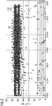
- FIG. 2 shows the air flow volume Q over a detection period t in a first room with a first room size.
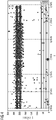
- FIG 3 shows the air flow volume Q over a detection period t in a second room with a second room size.
- Line L11 indicates 100% occupancy of the first room, line L12 80% occupancy, line L13 60% occupancy, line L14 40% occupancy, and line L15 20% occupancy of the first room.
Landscapes
- Engineering & Computer Science (AREA)
- Chemical & Material Sciences (AREA)
- Combustion & Propulsion (AREA)
- Mechanical Engineering (AREA)
- General Engineering & Computer Science (AREA)
- Physics & Mathematics (AREA)
- Fluid Mechanics (AREA)
- Ventilation (AREA)
Abstract

Description
- Die Erfindung betrifft ein Verfahren und eine Messvorrichtung zur Ermittlung des Luft-Flussvolumens durch ein Lüftungsrohr einer Belüftungsanlage, wobei das Lüftungsrohr einen Querschnitt aufweist und zwischen einem Luftzulauf und einem Luftablauf angeordnet ist
- In der Gebäudetechnik ist die Belüftung ein sehr wichtiges System, dessen Dimensionierung nicht immer einfach ist.
- Abhängig von verschiedenen Parametern, wie beispielsweise aufgrund der Art des installierten Lüftungssystems, des Verteilungssystems, der Größe der Räume und der Anzahl der Personen, die mit Frischluft versorgt werden sollen, gibt es verschiedene Methoden zur Messung des Luftstroms in oder zwischen Gebäudezonen.
- Zu Feststellung und Überprüfung der optimalen Auslegung eines solchen Systems werden häufig aufwändige Verfahren angewandt, wie der Gebläse-Tür-Test oder der Gas-Spuren-Test.
- Der Gebläse-Tür-Test (engl. "blower-door-test") umfasst einen kalibrierten Lüfter, ein Türverkleidungssystem und ein Druckmessgerät. Das Messgerät vergleicht den Druck im Gebäude oder im Raum mit dem Außendruck und wandelt die Druckdifferenz in eine Luftströmungsrate um.
- Im Gas-Spuren-Test "(engl. "tracer-gas-test") wird ein gasförmiges Markierungsmittel (Tracer) in einem Raum oder Gebäude verteilt und durch Verfolgen der Bewegung beziehungsweise der Konzentration des Tracer-Gases kann der Luftstrom bestimmt werden.
- Beide oben genannten Techniken sind jedoch mit einem hohen technischen und mechanischen Aufwand verbunden und im Kontext eines großen Gebäudekomplexes nicht einfach durchführbar.
- In modernen Gebäuden werden Lüftungssysteme häufig auf Grundlage von Erfahrungswerten dimensioniert, und die Feinabstimmung des Systems, wie nach der Inbetriebnahme, wird in der Regel vom Facility Management durchgeführt.
- Diese Optimierungsphase beinhaltet häufig das Anpassen von Einstellungen ("Try and Error"), und die Leistung steigt normalerweise mit der Zeit.
- Zusätzliche Faktoren wie eine wechselseitige Abhängigkeit von anderen Systemen, wie eine Heizung, und Anpassungen aufgrund saisonaler Betriebsarten erschweren ebenfalls die Feinabstimmung des Entlüftungssystems.
- Es ist Aufgabe der Erfindung ein Verfahren bereitzustellen, mit welchem auf eine einfache Weise ermittelt werden kann, ob das vorliegende Luft-Flussvolumen einer Belüftungsanlage eines Gebäudes ausreicht, um das Gebäude entsprechend zu belüften.
- Die erfindungsgemäße Aufgabe wird durch eine Vorrichtung eingangs genannter Art gelöst, indem eine Anlagen-Druck-Differenz zwischen dem Luftzulauf und dem Luftablauf gemessen wird, und mithilfe einer Luftdichte das Flussvolumen nach dem Zusammenhang
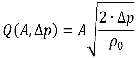
- Q
- ... Flussvolumen,
- Δp
- ... Anlagen-Druck-Differenz, und
- ρ0
- ... Luftdichte.
- Dadurch wird erreicht, dass für die Belüftungsanlage eine hinreichend genaue Abschätzung der vorliegenden Belüftungskapazität bezogen auf eine vorgegebene Belüftungslast unter Berücksichtigung besonders einfach zu erhebender Messwerte ermöglich wird.
- Es ist lediglich notwendig, Messwerte für die Zuluft und Abluft der Anlage messtechnisch mit entsprechenden Messmitteln zu erfassen.
- Für die Luftdichte kann ein Normwert angewandt werden, da über einen Erfassungszeitraum von konstanten Umgebungsbedingungen ausgegangen werden kann.
- Die Belüftungslast kann aus einschlägigen Belüftungs-Normen ermittelt werden, insbesondere bei einer vorgegebenen maximalen Raumbelegung, beispielsweise durch Kinder und Erwachsene.
- In einer Weiterbildung der Erfindung ist es vorgesehen, dass die Bestimmung der Anlagen-Druck-Differenz erfolgt, indem eine erste Druck-Differenz vor und nach einem, im Luftzulauf angeordneten, ersten Ventilator durch ein entsprechendes erstes Mittel erfasst wird, und eine zweite Druck-Differenz vor und nach einem, im Luftablauf angeordneten, zweiten Ventilator durch ein entsprechendes zweites Mittel erfasst wird, und die Anlagen-Druck-Different aus der ersten und zweiten Differenz gebildet wird.
- Unter dem Luftzulauf wird der Bereich zwischen der Schnittstelle zur Außenluft und der Schnittstelle zur Lüftungslast, wie einem Raum oder einem Gebäudebereich verstanden.
- Unter dem Luftablauf wird der Bereich zwischen der Schnittstelle von der Lüftungslast und der Schnittstelle zur Fortluft verstanden.
- In den Bereichen des Luftzulaufs und des Luftablaufs können jeweils ein oder mehrere Ventilatoren angeordnet werden, um eine Luftzirkulation zu unterstützen.
- Es können daher Messmittel zum Bestimmen eines Luftdruck-Unterschieds vor und nach dem jeweiligen Ventilator angebracht werden, welche erfindungsgemäß eingesetzt werden können und dabei besonders zuverlässig Messwerte ermitteln können, und darüber hinaus eine besonders einfache Integration in das Belüftungssystem erlauben.
- Dadurch kann auf besonders einfache Weise die Anlagen-Druck-Differenz ermittelt werden.
- In einer Weiterbildung der Erfindung ist es vorgesehen, dass das Luft-Flussvolumen kontinuierlich über einen Erfassungszeitraum ermittelt wird, und die Lüftungs-Last der Belüftungsanlage durch die Belegung der durch die Belüftungsanlage belüfteten Räume im Erfassungszeitraum erfasst wird, und aus der Lüftungs-Last und dem Luft-Flussvolumen ermittelt wird, ob eine hinreichende Belüftung erfolgt ist.
- Dadurch kann auf besonders einfache Weise eine lastabhängige und dynamische Überprüfung beziehungsweise Validierung eines Belüftungssystems durchgeführt werden.
- Die erfindungsgemäße Aufgabe wird auch von einer Vorrichtung eingangs genannter Art gelöst, welche das erfindungsgemäße Verfahren ausführt.
- Die Erfindung wird nachfolgend anhand eines in den beigeschlossenen Zeichnungen dargestellten Ausführungsbeispiels näher erläutert. In den Zeichnungen zeigt:
- Fig. 1
- ein Ausführungsbeispiel einer erfindungsgemäßen Messvorrichtung mit einer Gebäudebelüftungsanlage,
- Fig. 2
- ein erstes Diagramm mit einem zeitlichen Verlauf für ein ermitteltes Luft-Flussvolumen in einem ersten Raum,
- Fig. 3
- ein zweites Diagramm mit einem zeitlichen Verlauf für ein ermitteltes Luft-Flussvolumen in einem zweiten Raum,
- Fig. 4
- ein drittes Diagramm mit einem zeitlichen Verlauf für ein ermitteltes Luft-Flussvolumen in einem dritten Raum.
- Es ist klar, dass weitere nicht gezeigte Teile für den Betrieb einer Gebäudelüftungsanlage notwendig sind, wie Montageteile, elektrische Antriebe und Steuerungen. Zum besseren Verständnis werden diese Teile nicht dargestellt und beschrieben.
- Die Erfindung ist nicht auf die hier im Detail beschriebenen spezifischen Ausführungsformen beschränkt, sondern umfasst alle Varianten, Kombinationen und Modifikationen davon, die in den Rahmen der beigefügten Ansprüche fallen.
-
Fig. 1 zeigt ein Ausführungsbeispiel einer erfindungsgemäßen Messvorrichtung mit einer Gebäudebelüftungsanlage. - Die Belüftungsanlage weist einen Luftzulauf (AUL) und einem Luftablauf FOL auf.
- Der Luftzulauf AUL ist über ein Lüftungsrohr LR mit einem Querschnitt A mit dem Luftablauf FOL verbunden.
- Luftarten kennzeichnen in der Lüftungs- und Klimatechnik die verschiedenen Luftströme hinsichtlich der Verwendung.
- Außenluft als eine der Luftarten in der Lüftungs- und Klimatechnik ist die aus der Umgebung angesaugte Luft. Dies ist die Luft, so wie sie an der Außenseite des Gebäudes vorkommt.
- Sie darf jedoch nicht mit Frischluft verwechselt werden. Die Außenluft kann durch zwei Maßnahmen für die Lüftungs- und Klimatechnik verbessert werden: Dies ist zum einen die Wahl des Ansaugortes am Gebäude, an dem die Außenluft am wenigsten belastet ist, wie Sonneneinstrahlung, Autoabgase, Fortluftauslass, etc., zum anderen die Reinigung der Außenluft.
- Der Begriff Raumluft oder Innenraumluft beschreibt die Luft in Räumen. Im Bauwesen wird der Begriff vor allem in der Klima- und Lufttechnik verwendet, um die Luft im inneren von Räumen in Bauwerken von anderen Luftarten, wie zum Beispiel der Zu- und Abluft oder der Außenluft abzugrenzen.
- Fortluft ist in der Klimatechnik die ins Freie geblasene Abluft. Damit ist die Luft für die Klimatechnik nicht mehr nutzbar. Zuvor kann der Luft jedoch mit einer Wärme- oder Kälterückgewinnung Energie entzogen werden und diese dem Prozess wieder zugeführt werden.
- Abluft ist ganz allgemein die aus einem Raum frei oder gezwungen abströmende Luft.
- In der Figur ist ferner ein AUL-Temperaturfühler 1 gezeigt, welcher die Temperatur der Außenluft erfasst.
- Eine Absperrklappe 2 kann das Lüftungsrohr LR im Bereich des Luftzulaufs AUL versperren.
- Eine Absperrklappe 3 kann das Lüftungsrohr LR im Bereich des Luftablaufs FOL versperren.
- Eine Enteisungsklappe 4 kann das Lüftungsrohr LR im Bereich Luftzulaufs AUL mit dem Bereich des Luftablaufs FOL temporär verbinden.
- Eine Bypass-Klappe 5 kann einen Luft-Rückfluss im Lüftungsrohr LR reduzieren oder verhindern.
- Einen derartigen Fall kann ein entsprechender Differenzdrucksensor 6 erfassen und einer Steuereinrichtung signalisieren.
- Verschiedene Absperrklappen 7, 8, 9 und 10 für die Außenluft, die Fortluft und die Umluft können dazu verwendet werden, beispielsweise den Luft-Weg während einer Wartung gezielt umzuleiten.
- Ein Verdampfer 11 kann zur Erhöhung der Luftfeuchtigkeit im Belüftungssystem in das Lüftungsrohr LR eingefügt werden.
- Ein ZUL-Ventilator 12 dient dem Ansaugen von Außenluft und dem Zuführen von Zuluft.
- Ein Differenzdrucksensor 13 im ZUL-Ventilator 12 kann den Druckunterschied vor und nach dem ZUL-Ventilator 12 erfassen und einer Steuereinrichtung signalisieren.
- Weitere Absperrklappen 14 und 15 für die Zuluft und die Abluft können dazu verwendet werden, beispielsweise den Luft-Weg während einer Wartung gezielt zu verschließen.
- Ein Kondensator 16 kann zur Reduktion der Luftfeuchtigkeit im Belüftungssystem in das Lüftungsrohr LR eingefügt werden.
- Ein ABL-Ventilator 17 dient dem Ansaugen von Raumluft und dem Abführen von Fortluft.
- Ein Differenzdrucksensor 18 im ABL-Ventilator 17 kann den Druckunterschied vor und nach dem ABL-Ventilator 17 erfassen und einer Steuereinrichtung signalisieren.
- Ein ZUL-Temperaturfühler 19 kann die Temperatur der Zuluft erfassen und einer Steuereinrichtung signalisieren.
- Ein ABL-Temperaturfühler 20 kann die Temperatur der Abluft erfassen und einer Steuereinrichtung signalisieren.
- Ein Raum-Temperaturfühler 21 kann die ambiente RaumTemperatur erfassen und einer Steuereinrichtung signalisieren.
- Mittels eines Raumthermostats 22 kann eine Soll-Temperatur für ein Heizungssystem, welches in das Belüftungssystem integriert sein kann, gesetzt werden.
- Für das Raumthermostat 22 kann ein ZUL-Temperaturfühler 23 verwendet werden, um einen entsprechenden Temperaturwert anzuzeigen.
- In der Figur ist außerdem ein Beispiel für die erfindungsgemäße Messvorrichtung MV eingezeichnet, mittels welcher Druckdifferenzen p 1 und p 2 von den Differenzdrucksensoren 13 beziehungsweise 18 erfasst werden, und der Anlagen-Druck-Differenz Δp zwischen dem Luftzulauf AUL und dem Luftablauf FOL gemessen wird, und mithilfe einer Luftdichte ρ 0 das Flussvolumen Q nach dem Zusammenhang

- Aus dem Rohrdurchmesser des Lüftungsrohres LR von 50 cm ergibt sich der Querschnitt A der Lüftungsrohres LR von etwa 0,2 m2, woraus sich ein idealer durchschnittlicher Luftfluss von etwa 15,000 m3/h ergibt.
- Aufgrund der Komplexität des Entlüftungssystems der Schule leiten wir diese Standardmaßnahmenl für alle in Frage kommenden Rohre im Entlüftungssystem des Klassenzimmers ab. Diese Annahme kann jedoch leicht an die Realitäten eines Betongebäudes angepasst werden. Zweitens ist
- Die Temperatur der Zu- und Abluft ist keinen größeren Schwankungen ausgesetzt.
- Der Jahresdurchschnitt liegt meist bei 20 °C bis 25 °C.
- Für die Luftdichte ρ 0 kann daher vereinfacht ein konstanter Normwert von 1.21 km/m3 bei 20°C angewandt werden.
- Die Bestimmung der Anlagen-Druck-Differenz (Δp) erfolgt, indem zunächst eine erste Druck-Differenz p 1 vor und nach dem, im Luftzulauf AUL angeordneten, ersten Ventilator 12 durch ein entsprechendes erstes Mittel 13 erfasst wird.
- Ferner wird eine zweite Druck-Differenz p 2 vor und nach dem, im Luftablauf FOL angeordneten, zweiten Ventilator 17 durch ein entsprechendes zweites Mittel 18 erfasst.
- Die Anlagen-Druck-Different Δp wird aus der ersten und zweiten Differenz p 1, p 2 gebildet.
- Das Luft-Flussvolumen Q wird kontinuierlich über die Zeit t über einen Erfassungszeitraum ermittelt.
- Die Lüftungs-Last der Belüftungsanlage wird durch die Belegung eines durch die Belüftungsanlage belüfteten Raums R im Erfassungszeitraum erfasst.
- Aus der Lüftungs-Last und dem Luft-Flussvolumen Q wird ermittelt, ob eine hinreichende Belüftung vorliegt.
- Faktoren hinsichtlich einer Lüftungskanalkonfiguration oder eine Montage des Lüftungsrohres LR, eine Rohrlänge, ein Rohrreibungskoeffizient sowie Änderungen in der Geometrie oder im Material können zu Strömungsverlusten führen.
- Die Einbeziehung dieser Faktoren würde jedoch die Abschätzung der Belüftungsfunktion komplexer machen.
- Die Erfindung soll jedoch eine sehr einfache Form der Abschätzung unter Berücksichtigung besonders einfach zu erhebender Messwerte ermöglichen, ohne dass ein grundsätzliche Aussagequalität der Schätzung eingeschränkt wird.
- Aus der genannten Formel lässt sich nicht nur das Luft-Flussvolumen Q ermittelt, sondern auf einfache Weise der Luftfluss pro Sekunde oder pro Stunde ableiten.
- Für weitere Betrachtungen muss die Last des Belüftungssystem einbezogen werden, welche sich auf der Belegung des Raumes R ergeben kann.
- Beispielsweise kann für eine Schulklasse als Raum R eine maximale Belegung von 25 Kinder sowie zwei Erwachsene angenommen werden.
- Alternativ kann für eine Kleingruppenraum als Raum R eine maximale Belegung von zehn Kinder sowie einem Erwachsenen angenommen werden.
- Mithilfe des ANSI/ASHRAE Standards 62.1-2019 (American Society of Heating and Air-Conditioning Engineers, 2019, Ventilation for Acceptable Indoor Air Quality) kann eine benötigter Luft-Flussvolumen Q beziehungsweise ein entsprechender Luftfluss ermittelt werden.
- Der ASHRAE-Standard schlägt 0,283 m3/min pro Kind (9-10 Jahre) und 0,43 m3/min pro Erwachsenen als ideale Belüftung für eine akzeptable Raumluftqualität vor.
-
Fig. 2 zeigt das Luft-Flussvolumen Q über einen Erfassungszeitraum t in einem ersten Raum mit einer ersten Raumgröße. -
Fig. 3 zeigt das Luft-Flussvolumen Q über einen Erfassungszeitraum t in einem zweiten Raum mit einer zweiten Raumgröße. -
Fig. 4 zeigt das Luft-Flussvolumen Q über einen Erfassungszeitraum t in einem dritten Raum mit einer dritten Raumgröße. - In den in
Fig. 2 bis Fig. 4 dargestellten zeitlichen Verläufen von Luft-Flussvolumen Q ist sowohl der Luftzufluss als auch Abfluss dargestellt. - Ferner sind die aus der Norm ASHRAE 62.1-2019 vorgegebenen Grenzwerte für eine optimale Belüftung mit unterschiedlicher Raumbelegung erkennbar.
- Die Linie L11 bezeichnet eine 100% Belegung des ersten Raums, die Linie L12 eine 80% Belegung, die Linie L13 eine 60% Belegung, die Linie L14 eine 40% Belegung und die Linie L15 eine 20% Belegung des ersten Raums.
- Es ist aus der Figur erkennbar, dass das Lüftungssystem mit großen Reserven eine 100% Belegung beherrschen kann und das Lüftungssystem daher optimal dimensioniert ist.
- Dadurch wird klar, dass das erfindungsgemäße Verfahren auf einfache und effiziente Weise eine Validierung eines Lüftungssystem erlaubt, bei welcher nur die Luftdruckverhältnisse an den Ventilatoren im Zuluft- und Abluft-Bereich des Lüftungsrohres ermittelt werden müssen.
- Mit anderen Worten zeigen die
Fig. 2-4 , dass die Lüftungssysteme in den jeweiligen Räumen im Beispielgebäude unter idealen Bedingungen dem Luftbedarfsprofil dieser Gebäudezonen zu entsprechen scheinen. - Beim Vergleich eines berechneten Luftstromvolumens für Zu- und Abluft mit dem idealen Belüftungsvolumen gemäß ASHRAE-Standard 62.1-2019 bei unterschiedlichen Belegungszuständen, welche durch die Grenzwertlinien L11-L15, L21-L24, L31-L34 dargestellt sind, wird genügend Luft durch die Belüftung der Schule bewegt System zur Aufrechterhaltung eines akzeptablen Raumklimas für die Insassen.
- Daher kann eine Unterdimensionierung des Lüftungssystems nicht bestätigt werden.
- Die Ausführungen gelten für
Fig. 3 undFig. 4 dementsprechend. -
- 1
- AUL-Temperaturfühler
- 2
- Absperrklappe AUL
- 3
- Absperrklappe FOL
- 4
- Enteisungsklappe
- 5
- Bypass-Klappe
- 6
- Differenzdrucksensor
- 7
- AUL-Klappe
- 8
- FOL-Klappe
- 9, 10
- UML-Klappe
- 11
- Verdampfer
- 12
- ZUL-Ventilator
- 13
- Differenzdrucksensor ZUL-Ventilator
- 14
- Absperrklappe ZUL
- 15
- Absperrklappe ABL
- 16
- Kondensator
- 17
- ABL-Ventilator
- 18
- Differenzdrucksensor ABL-Ventilator
- 19
- ZUL-Temperaturfühler
- 20
- ABL-Temperaturfühler
- 21
- ZUL-Temperaturfühler zur Anzeige
- 22
- Raumtemperaturfühler
- 23
- Raumthermostat, Notthermostat
- A
- Querschnitt des Lüftungsrohrs
- ABL
- Abluft
- AUL
- Außenluft
- FOL
- Fortluft
- UML
- Umluft
- ZUL
- Zuluft
- MV
- Messvorrichtung
- LR
- Lüftungsrohr
- L11-L15, L21-L24, L31-L34
- Linie für Norm-Grenzwert
- Δp
- Anlagen-Druck-Differenz
- Q
- Luft-Flussvolumen
- Q1
- ABL-Luft-Flussvolumen
- Q2
- ZUL-Luft-Flussvolumen
- R
- Raum
- ρ0
- Luftdichte
- t
- Zeit
Claims (4)
- Verfahren zur Ermittlung des Luft-Flussvolumens (Q) durch ein Lüftungsrohr (LR) einer Belüftungsanlage, wobei das Lüftungsrohr einen Querschnitt (A) aufweist und zwischen einem Luftzulauf (AUL) und einem Luftablauf (FOL) angeordnet ist, dadurch gekennzeichnet, dass eine Anlagen-Druck-Differenz (Δp) zwischen dem Luftzulauf (AUL) und dem Luftablauf (FOL) gemessen wird, und mithilfe einer Luftdichte (ρ 0) das Flussvolumen (Q) nach dem Zusammenhang

- Verfahren nach dem vorhergehenden Anspruch, wobei die Bestimmung der Anlagen-Druck-Differenz (Δp) erfolgt, indem eine erste Druck-Differenz (p 1) vor und nach einem, im Luftzulauf (AUL) angeordneten, ersten Ventilator (12) durch ein entsprechendes erstes Mittel (13) erfasst wird, und eine zweite Druck-Differenz (p 2) vor und nach einem, im Luftablauf (FOL) angeordneten, zweiten Ventilator (17) durch ein entsprechendes zweites Mittel (18) erfasst wird, und die Anlagen-Druck-Different (Δp) aus der ersten und zweiten Differenz (p 1, p 2) gebildet wird.
- Verfahren nach einem der vorhergehenden Ansprüche, wobei das Luft-Flussvolumen (Q) kontinuierlich über einen Erfassungszeitraum (t) ermittelt wird, und die Lüftungs-Last (VR) der Belüftungsanlage durch die Belegung der durch die Belüftungsanlage belüfteten Räume (R) im Erfassungszeitraum erfasst wird, und aus der Lüftungs-Last (VR) und dem Luft-Flussvolumen (Q) ermittelt wird, ob eine hinreichende Belüftung erfolgt ist.
- Messvorrichtung (MV) mit einem Prozessor und einem Speicher zur Ermittlung des Luft-Flussvolumens (Q) durch ein Lüftungsrohr (LR) einer Belüftungsanlage, welches Lüftungsrohr (LR) einen Querschnitt (A) zwischen einem Luftzulauf (AUL) und einem Luftablauf (FOL) aufweist, und bei dem Luftzulauf (AUL) und dem Luftablauf (FOL) jeweils Mittel (13, 18) zum Messen eines jeweiligen Luftdrucks vorgesehen sind, dadurch gekennzeichnet, dass die Messvorrichtung (MV) dazu eingerichtet ist, das Verfahren der vorhergehenden Ansprüche auszuführen.
Priority Applications (1)
| Application Number | Priority Date | Filing Date | Title |
|---|---|---|---|
| EP20204721.3A EP3992536B1 (de) | 2020-10-29 | 2020-10-29 | Verfahren und vorrichtung zur ermittlung des luft-flussvolumens durch ein lüftungsrohr einer belüftungsanlage |
Applications Claiming Priority (1)
| Application Number | Priority Date | Filing Date | Title |
|---|---|---|---|
| EP20204721.3A EP3992536B1 (de) | 2020-10-29 | 2020-10-29 | Verfahren und vorrichtung zur ermittlung des luft-flussvolumens durch ein lüftungsrohr einer belüftungsanlage |
Publications (2)
| Publication Number | Publication Date |
|---|---|
| EP3992536A1 true EP3992536A1 (de) | 2022-05-04 |
| EP3992536B1 EP3992536B1 (de) | 2024-06-19 |
Family
ID=73039904
Family Applications (1)
| Application Number | Title | Priority Date | Filing Date |
|---|---|---|---|
| EP20204721.3A Active EP3992536B1 (de) | 2020-10-29 | 2020-10-29 | Verfahren und vorrichtung zur ermittlung des luft-flussvolumens durch ein lüftungsrohr einer belüftungsanlage |
Country Status (1)
| Country | Link |
|---|---|
| EP (1) | EP3992536B1 (de) |
Citations (4)
| Publication number | Priority date | Publication date | Assignee | Title |
|---|---|---|---|---|
| KR100966077B1 (ko) * | 2009-12-21 | 2010-06-25 | 한국건설기술연구원 | 기계식 및 자연식 혼합형 하이브리드 환기장치 및 환기방법 |
| EP3002525A1 (de) * | 2014-09-30 | 2016-04-06 | GEA Air Treatment GmbH | Verfahren zum betreiben einer belüftungsanlage und belüftungsanlage |
| CN111380145A (zh) * | 2020-03-19 | 2020-07-07 | 中国建筑科学研究院有限公司 | 新风机的新风量实时监测的方法 |
| CN111306689B (zh) * | 2020-02-24 | 2020-10-27 | 中国人民解放军火箭军工程设计研究院 | 一种地下通风系统 |
-
2020
- 2020-10-29 EP EP20204721.3A patent/EP3992536B1/de active Active
Patent Citations (4)
| Publication number | Priority date | Publication date | Assignee | Title |
|---|---|---|---|---|
| KR100966077B1 (ko) * | 2009-12-21 | 2010-06-25 | 한국건설기술연구원 | 기계식 및 자연식 혼합형 하이브리드 환기장치 및 환기방법 |
| EP3002525A1 (de) * | 2014-09-30 | 2016-04-06 | GEA Air Treatment GmbH | Verfahren zum betreiben einer belüftungsanlage und belüftungsanlage |
| CN111306689B (zh) * | 2020-02-24 | 2020-10-27 | 中国人民解放军火箭军工程设计研究院 | 一种地下通风系统 |
| CN111380145A (zh) * | 2020-03-19 | 2020-07-07 | 中国建筑科学研究院有限公司 | 新风机的新风量实时监测的方法 |
Also Published As
| Publication number | Publication date |
|---|---|
| EP3992536B1 (de) | 2024-06-19 |
Similar Documents
| Publication | Publication Date | Title |
|---|---|---|
| EP2697572B1 (de) | Automatisierte funktionsdiagnose | |
| DE4031113C2 (de) | ||
| EP2726792B1 (de) | Verfahren und vorrichtungen zum abgleichen einer gruppe von verbrauchern in einem fluidtransportsystem | |
| EP2870414B1 (de) | Verfahren zum betrieb eines wärmetauschers sowie hvac-anlage zur durchführung des verfahrens | |
| DE2108081A1 (de) | Vorrichtung und Verfahren zum Ausgleichen von Durchsatzstromen in Verteilersystemen | |
| EP2947396B1 (de) | Verfahren zum belüften eines raumes sowie lüftungsanlage hierfür | |
| EP1878979A1 (de) | Verfahren und Vorrichtung zum kontrollierten Lüften gegen Schimmelbildung | |
| DE19548108A1 (de) | Vorrichtung und Verfahren, um plötzliche Druckänderungen in Fahrzeugen, insbesondere Bodenfahrzeugen, zu vermeiden | |
| DE102016125405A1 (de) | Verfahren und Vorrichtung zur Belüftung eines Tunnelbauwerks | |
| DE102015117665A1 (de) | Vorrichtung zum klimatisieren eines innenraums eines fahrzeugs, insbesondere eines schienenfahrzeugs | |
| EP4179265B1 (de) | Verfahren und ventilatorsystem zur ermittlung eines aktuellen arbeitspunktes einer ventilatoreinheit | |
| DE102015200996A1 (de) | Verfahren und Vorrichtung zur Standzeitüberwachung eines Filters | |
| EP3098527B1 (de) | Verfahren zum betreiben einer lüftungseinrichtung für einen raum sowie entsprechende lüftungseinrichtung | |
| EP3992536B1 (de) | Verfahren und vorrichtung zur ermittlung des luft-flussvolumens durch ein lüftungsrohr einer belüftungsanlage | |
| AT511470A4 (de) | Vorrichtung und verfahren zur regelung einer frischluftzufuhr bei einer vorrichtung zum kühlen, heizen und/oder lüften eines gebäudes | |
| EP3534079A1 (de) | Verfahren zum ermitteln der einzelraum-luftvolumenströme bei zentralen lüftungssystemen und zum pneumatischen abgleich von lüftungssystemen | |
| EP0109503B1 (de) | Regelventil zum Konstanthalten des Volumenstromes, insbesondere in lufttechnischen Anlagen | |
| DE10108847C1 (de) | Verfahren und Vorrichtung zur Regelung der Raumlufttemperatur | |
| DE10316352A1 (de) | Klimaanlage mit einem Kältemittelkreislauf | |
| DE102021113659B4 (de) | Verfahren, Steuereinrichtung sowie Computerprogrammprodukt zur Regelung eines Raumklimas in einem Innenraum eines Kraftfahrzeugs | |
| EP1628087B1 (de) | Verfahren und Einrichtung zum Ermitteln einer Dichtheit eines Raums | |
| EP1846886A1 (de) | Verfahren und einrichtung zur energie- und medienverbrauchserfassung und nutzerspezifischen umlage bei gemeinschaftlich genutzten raumlufttechnischen anlagen | |
| EP1550927B1 (de) | Verfahren und Anordnung sowie Computerprogramm zur Ermittlung einer Steuergrösse für eine Temperaturregelung für ein System | |
| DE102021116154A1 (de) | Überwachungsvorrichtung und Verfahren zur Überwachung der Qualität einer Gasatmosphäre | |
| WO2021023448A1 (de) | Verfahren zur regelung eines klimageräts |
Legal Events
| Date | Code | Title | Description |
|---|---|---|---|
| PUAI | Public reference made under article 153(3) epc to a published international application that has entered the european phase |
Free format text: ORIGINAL CODE: 0009012 |
|
| STAA | Information on the status of an ep patent application or granted ep patent |
Free format text: STATUS: THE APPLICATION HAS BEEN PUBLISHED |
|
| AK | Designated contracting states |
Kind code of ref document: A1 Designated state(s): AL AT BE BG CH CY CZ DE DK EE ES FI FR GB GR HR HU IE IS IT LI LT LU LV MC MK MT NL NO PL PT RO RS SE SI SK SM TR |
|
| STAA | Information on the status of an ep patent application or granted ep patent |
Free format text: STATUS: REQUEST FOR EXAMINATION WAS MADE |
|
| 17P | Request for examination filed |
Effective date: 20221005 |
|
| RBV | Designated contracting states (corrected) |
Designated state(s): AL AT BE BG CH CY CZ DE DK EE ES FI FR GB GR HR HU IE IS IT LI LT LU LV MC MK MT NL NO PL PT RO RS SE SI SK SM TR |
|
| RIC1 | Information provided on ipc code assigned before grant |
Ipc: F24F 110/40 20180101ALN20231211BHEP Ipc: F24F 110/30 20180101ALN20231211BHEP Ipc: F24F 11/74 20180101ALI20231211BHEP Ipc: F24F 11/48 20180101ALI20231211BHEP Ipc: F24F 11/00 20180101AFI20231211BHEP |
|
| RIC1 | Information provided on ipc code assigned before grant |
Ipc: F24F 110/40 20180101ALN20231219BHEP Ipc: F24F 110/30 20180101ALN20231219BHEP Ipc: F24F 11/74 20180101ALI20231219BHEP Ipc: F24F 11/48 20180101ALI20231219BHEP Ipc: F24F 11/00 20180101AFI20231219BHEP |
|
| GRAP | Despatch of communication of intention to grant a patent |
Free format text: ORIGINAL CODE: EPIDOSNIGR1 |
|
| STAA | Information on the status of an ep patent application or granted ep patent |
Free format text: STATUS: GRANT OF PATENT IS INTENDED |
|
| INTG | Intention to grant announced |
Effective date: 20240126 |
|
| GRAS | Grant fee paid |
Free format text: ORIGINAL CODE: EPIDOSNIGR3 |
|
| GRAA | (expected) grant |
Free format text: ORIGINAL CODE: 0009210 |
|
| STAA | Information on the status of an ep patent application or granted ep patent |
Free format text: STATUS: THE PATENT HAS BEEN GRANTED |
|
| AK | Designated contracting states |
Kind code of ref document: B1 Designated state(s): AL AT BE BG CH CY CZ DE DK EE ES FI FR GB GR HR HU IE IS IT LI LT LU LV MC MK MT NL NO PL PT RO RS SE SI SK SM TR |
|
| REG | Reference to a national code |
Ref country code: GB Ref legal event code: FG4D Free format text: NOT ENGLISH |
|
| REG | Reference to a national code |
Ref country code: CH Ref legal event code: EP |
|
| REG | Reference to a national code |
Ref country code: DE Ref legal event code: R096 Ref document number: 502020008305 Country of ref document: DE |
|
| PG25 | Lapsed in a contracting state [announced via postgrant information from national office to epo] |
Ref country code: BG Free format text: LAPSE BECAUSE OF FAILURE TO SUBMIT A TRANSLATION OF THE DESCRIPTION OR TO PAY THE FEE WITHIN THE PRESCRIBED TIME-LIMIT Effective date: 20240619 |
|
| PG25 | Lapsed in a contracting state [announced via postgrant information from national office to epo] |
Ref country code: FI Free format text: LAPSE BECAUSE OF FAILURE TO SUBMIT A TRANSLATION OF THE DESCRIPTION OR TO PAY THE FEE WITHIN THE PRESCRIBED TIME-LIMIT Effective date: 20240619 Ref country code: HR Free format text: LAPSE BECAUSE OF FAILURE TO SUBMIT A TRANSLATION OF THE DESCRIPTION OR TO PAY THE FEE WITHIN THE PRESCRIBED TIME-LIMIT Effective date: 20240619 |
|
| REG | Reference to a national code |
Ref country code: LT Ref legal event code: MG9D |
|
| PG25 | Lapsed in a contracting state [announced via postgrant information from national office to epo] |
Ref country code: GR Free format text: LAPSE BECAUSE OF FAILURE TO SUBMIT A TRANSLATION OF THE DESCRIPTION OR TO PAY THE FEE WITHIN THE PRESCRIBED TIME-LIMIT Effective date: 20240920 |
|
| REG | Reference to a national code |
Ref country code: NL Ref legal event code: MP Effective date: 20240619 |
|
| PG25 | Lapsed in a contracting state [announced via postgrant information from national office to epo] |
Ref country code: LV Free format text: LAPSE BECAUSE OF FAILURE TO SUBMIT A TRANSLATION OF THE DESCRIPTION OR TO PAY THE FEE WITHIN THE PRESCRIBED TIME-LIMIT Effective date: 20240619 |
|
| PG25 | Lapsed in a contracting state [announced via postgrant information from national office to epo] |
Ref country code: NO Free format text: LAPSE BECAUSE OF FAILURE TO SUBMIT A TRANSLATION OF THE DESCRIPTION OR TO PAY THE FEE WITHIN THE PRESCRIBED TIME-LIMIT Effective date: 20240919 Ref country code: LV Free format text: LAPSE BECAUSE OF FAILURE TO SUBMIT A TRANSLATION OF THE DESCRIPTION OR TO PAY THE FEE WITHIN THE PRESCRIBED TIME-LIMIT Effective date: 20240619 Ref country code: HR Free format text: LAPSE BECAUSE OF FAILURE TO SUBMIT A TRANSLATION OF THE DESCRIPTION OR TO PAY THE FEE WITHIN THE PRESCRIBED TIME-LIMIT Effective date: 20240619 Ref country code: GR Free format text: LAPSE BECAUSE OF FAILURE TO SUBMIT A TRANSLATION OF THE DESCRIPTION OR TO PAY THE FEE WITHIN THE PRESCRIBED TIME-LIMIT Effective date: 20240920 Ref country code: FI Free format text: LAPSE BECAUSE OF FAILURE TO SUBMIT A TRANSLATION OF THE DESCRIPTION OR TO PAY THE FEE WITHIN THE PRESCRIBED TIME-LIMIT Effective date: 20240619 Ref country code: BG Free format text: LAPSE BECAUSE OF FAILURE TO SUBMIT A TRANSLATION OF THE DESCRIPTION OR TO PAY THE FEE WITHIN THE PRESCRIBED TIME-LIMIT Effective date: 20240619 Ref country code: RS Free format text: LAPSE BECAUSE OF FAILURE TO SUBMIT A TRANSLATION OF THE DESCRIPTION OR TO PAY THE FEE WITHIN THE PRESCRIBED TIME-LIMIT Effective date: 20240919 |
|
| PG25 | Lapsed in a contracting state [announced via postgrant information from national office to epo] |
Ref country code: NL Free format text: LAPSE BECAUSE OF FAILURE TO SUBMIT A TRANSLATION OF THE DESCRIPTION OR TO PAY THE FEE WITHIN THE PRESCRIBED TIME-LIMIT Effective date: 20240619 |
|
| PG25 | Lapsed in a contracting state [announced via postgrant information from national office to epo] |
Ref country code: NL Free format text: LAPSE BECAUSE OF FAILURE TO SUBMIT A TRANSLATION OF THE DESCRIPTION OR TO PAY THE FEE WITHIN THE PRESCRIBED TIME-LIMIT Effective date: 20240619 |
|
| PG25 | Lapsed in a contracting state [announced via postgrant information from national office to epo] |
Ref country code: PT Free format text: LAPSE BECAUSE OF FAILURE TO SUBMIT A TRANSLATION OF THE DESCRIPTION OR TO PAY THE FEE WITHIN THE PRESCRIBED TIME-LIMIT Effective date: 20241021 |
|
| PG25 | Lapsed in a contracting state [announced via postgrant information from national office to epo] |
Ref country code: PT Free format text: LAPSE BECAUSE OF FAILURE TO SUBMIT A TRANSLATION OF THE DESCRIPTION OR TO PAY THE FEE WITHIN THE PRESCRIBED TIME-LIMIT Effective date: 20241021 |
|
| PG25 | Lapsed in a contracting state [announced via postgrant information from national office to epo] |
Ref country code: PL Free format text: LAPSE BECAUSE OF FAILURE TO SUBMIT A TRANSLATION OF THE DESCRIPTION OR TO PAY THE FEE WITHIN THE PRESCRIBED TIME-LIMIT Effective date: 20240619 |
|
| PG25 | Lapsed in a contracting state [announced via postgrant information from national office to epo] |
Ref country code: EE Free format text: LAPSE BECAUSE OF FAILURE TO SUBMIT A TRANSLATION OF THE DESCRIPTION OR TO PAY THE FEE WITHIN THE PRESCRIBED TIME-LIMIT Effective date: 20240619 |
|
| PG25 | Lapsed in a contracting state [announced via postgrant information from national office to epo] |
Ref country code: IS Free format text: LAPSE BECAUSE OF FAILURE TO SUBMIT A TRANSLATION OF THE DESCRIPTION OR TO PAY THE FEE WITHIN THE PRESCRIBED TIME-LIMIT Effective date: 20241019 |
|
| PG25 | Lapsed in a contracting state [announced via postgrant information from national office to epo] |
Ref country code: CZ Free format text: LAPSE BECAUSE OF FAILURE TO SUBMIT A TRANSLATION OF THE DESCRIPTION OR TO PAY THE FEE WITHIN THE PRESCRIBED TIME-LIMIT Effective date: 20240619 |
|
| PG25 | Lapsed in a contracting state [announced via postgrant information from national office to epo] |
Ref country code: SK Free format text: LAPSE BECAUSE OF FAILURE TO SUBMIT A TRANSLATION OF THE DESCRIPTION OR TO PAY THE FEE WITHIN THE PRESCRIBED TIME-LIMIT Effective date: 20240619 Ref country code: RO Free format text: LAPSE BECAUSE OF FAILURE TO SUBMIT A TRANSLATION OF THE DESCRIPTION OR TO PAY THE FEE WITHIN THE PRESCRIBED TIME-LIMIT Effective date: 20240619 |
|
| PG25 | Lapsed in a contracting state [announced via postgrant information from national office to epo] |
Ref country code: SM Free format text: LAPSE BECAUSE OF FAILURE TO SUBMIT A TRANSLATION OF THE DESCRIPTION OR TO PAY THE FEE WITHIN THE PRESCRIBED TIME-LIMIT Effective date: 20240619 Ref country code: ES Free format text: LAPSE BECAUSE OF FAILURE TO SUBMIT A TRANSLATION OF THE DESCRIPTION OR TO PAY THE FEE WITHIN THE PRESCRIBED TIME-LIMIT Effective date: 20240619 |
|
| PG25 | Lapsed in a contracting state [announced via postgrant information from national office to epo] |
Ref country code: SM Free format text: LAPSE BECAUSE OF FAILURE TO SUBMIT A TRANSLATION OF THE DESCRIPTION OR TO PAY THE FEE WITHIN THE PRESCRIBED TIME-LIMIT Effective date: 20240619 Ref country code: SK Free format text: LAPSE BECAUSE OF FAILURE TO SUBMIT A TRANSLATION OF THE DESCRIPTION OR TO PAY THE FEE WITHIN THE PRESCRIBED TIME-LIMIT Effective date: 20240619 Ref country code: RO Free format text: LAPSE BECAUSE OF FAILURE TO SUBMIT A TRANSLATION OF THE DESCRIPTION OR TO PAY THE FEE WITHIN THE PRESCRIBED TIME-LIMIT Effective date: 20240619 Ref country code: PL Free format text: LAPSE BECAUSE OF FAILURE TO SUBMIT A TRANSLATION OF THE DESCRIPTION OR TO PAY THE FEE WITHIN THE PRESCRIBED TIME-LIMIT Effective date: 20240619 Ref country code: IS Free format text: LAPSE BECAUSE OF FAILURE TO SUBMIT A TRANSLATION OF THE DESCRIPTION OR TO PAY THE FEE WITHIN THE PRESCRIBED TIME-LIMIT Effective date: 20241019 Ref country code: ES Free format text: LAPSE BECAUSE OF FAILURE TO SUBMIT A TRANSLATION OF THE DESCRIPTION OR TO PAY THE FEE WITHIN THE PRESCRIBED TIME-LIMIT Effective date: 20240619 Ref country code: EE Free format text: LAPSE BECAUSE OF FAILURE TO SUBMIT A TRANSLATION OF THE DESCRIPTION OR TO PAY THE FEE WITHIN THE PRESCRIBED TIME-LIMIT Effective date: 20240619 Ref country code: CZ Free format text: LAPSE BECAUSE OF FAILURE TO SUBMIT A TRANSLATION OF THE DESCRIPTION OR TO PAY THE FEE WITHIN THE PRESCRIBED TIME-LIMIT Effective date: 20240619 |
|
| PG25 | Lapsed in a contracting state [announced via postgrant information from national office to epo] |
Ref country code: IT Free format text: LAPSE BECAUSE OF FAILURE TO SUBMIT A TRANSLATION OF THE DESCRIPTION OR TO PAY THE FEE WITHIN THE PRESCRIBED TIME-LIMIT Effective date: 20240619 |
|
| REG | Reference to a national code |
Ref country code: DE Ref legal event code: R097 Ref document number: 502020008305 Country of ref document: DE |
|
| PG25 | Lapsed in a contracting state [announced via postgrant information from national office to epo] |
Ref country code: DK Free format text: LAPSE BECAUSE OF FAILURE TO SUBMIT A TRANSLATION OF THE DESCRIPTION OR TO PAY THE FEE WITHIN THE PRESCRIBED TIME-LIMIT Effective date: 20240619 |
|
| PLBE | No opposition filed within time limit |
Free format text: ORIGINAL CODE: 0009261 |
|
| STAA | Information on the status of an ep patent application or granted ep patent |
Free format text: STATUS: NO OPPOSITION FILED WITHIN TIME LIMIT |
|
| REG | Reference to a national code |
Ref country code: DE Ref legal event code: R119 Ref document number: 502020008305 Country of ref document: DE |
|
| 26N | No opposition filed |
Effective date: 20250320 |
|
| REG | Reference to a national code |
Ref country code: CH Ref legal event code: PL |
|
| GBPC | Gb: european patent ceased through non-payment of renewal fee |
Effective date: 20241029 |
|
| PG25 | Lapsed in a contracting state [announced via postgrant information from national office to epo] |
Ref country code: MC Free format text: LAPSE BECAUSE OF FAILURE TO SUBMIT A TRANSLATION OF THE DESCRIPTION OR TO PAY THE FEE WITHIN THE PRESCRIBED TIME-LIMIT Effective date: 20240619 |
|
| PG25 | Lapsed in a contracting state [announced via postgrant information from national office to epo] |
Ref country code: DE Free format text: LAPSE BECAUSE OF NON-PAYMENT OF DUE FEES Effective date: 20250501 |
|
| PG25 | Lapsed in a contracting state [announced via postgrant information from national office to epo] |
Ref country code: GB Free format text: LAPSE BECAUSE OF NON-PAYMENT OF DUE FEES Effective date: 20241029 |
|
| PG25 | Lapsed in a contracting state [announced via postgrant information from national office to epo] |
Ref country code: BE Free format text: LAPSE BECAUSE OF NON-PAYMENT OF DUE FEES Effective date: 20241031 Ref country code: LU Free format text: LAPSE BECAUSE OF NON-PAYMENT OF DUE FEES Effective date: 20241029 |
|
| PG25 | Lapsed in a contracting state [announced via postgrant information from national office to epo] |
Ref country code: FR Free format text: LAPSE BECAUSE OF NON-PAYMENT OF DUE FEES Effective date: 20241031 |
|
| PG25 | Lapsed in a contracting state [announced via postgrant information from national office to epo] |
Ref country code: CH Free format text: LAPSE BECAUSE OF NON-PAYMENT OF DUE FEES Effective date: 20241031 |
|
| REG | Reference to a national code |
Ref country code: BE Ref legal event code: MM Effective date: 20241031 |
|
| PG25 | Lapsed in a contracting state [announced via postgrant information from national office to epo] |
Ref country code: SE Free format text: LAPSE BECAUSE OF FAILURE TO SUBMIT A TRANSLATION OF THE DESCRIPTION OR TO PAY THE FEE WITHIN THE PRESCRIBED TIME-LIMIT Effective date: 20240619 |
|
| PG25 | Lapsed in a contracting state [announced via postgrant information from national office to epo] |
Ref country code: IE Free format text: LAPSE BECAUSE OF NON-PAYMENT OF DUE FEES Effective date: 20241029 |
|
| PGFP | Annual fee paid to national office [announced via postgrant information from national office to epo] |
Ref country code: AT Payment date: 20260113 Year of fee payment: 5 |
|
| PG25 | Lapsed in a contracting state [announced via postgrant information from national office to epo] |
Ref country code: HU Free format text: LAPSE BECAUSE OF FAILURE TO SUBMIT A TRANSLATION OF THE DESCRIPTION OR TO PAY THE FEE WITHIN THE PRESCRIBED TIME-LIMIT; INVALID AB INITIO Effective date: 20201029 |
|
| PG25 | Lapsed in a contracting state [announced via postgrant information from national office to epo] |
Ref country code: CY Free format text: LAPSE BECAUSE OF FAILURE TO SUBMIT A TRANSLATION OF THE DESCRIPTION OR TO PAY THE FEE WITHIN THE PRESCRIBED TIME-LIMIT; INVALID AB INITIO Effective date: 20201029 |