EP3992312A1 - Method for producing non-oriented electromagnetic steel sheet, method for producing motor core, and motor core - Google Patents
Method for producing non-oriented electromagnetic steel sheet, method for producing motor core, and motor core Download PDFInfo
- Publication number
- EP3992312A1 EP3992312A1 EP20832967.2A EP20832967A EP3992312A1 EP 3992312 A1 EP3992312 A1 EP 3992312A1 EP 20832967 A EP20832967 A EP 20832967A EP 3992312 A1 EP3992312 A1 EP 3992312A1
- Authority
- EP
- European Patent Office
- Prior art keywords
- mass
- steel sheet
- oriented electrical
- steel
- stress
- Prior art date
- Legal status (The legal status is an assumption and is not a legal conclusion. Google has not performed a legal analysis and makes no representation as to the accuracy of the status listed.)
- Pending
Links
Images

Classifications
-
- H—ELECTRICITY
- H02—GENERATION; CONVERSION OR DISTRIBUTION OF ELECTRIC POWER
- H02K—DYNAMO-ELECTRIC MACHINES
- H02K1/00—Details of the magnetic circuit
- H02K1/02—Details of the magnetic circuit characterised by the magnetic material
-
- C—CHEMISTRY; METALLURGY
- C21—METALLURGY OF IRON
- C21D—MODIFYING THE PHYSICAL STRUCTURE OF FERROUS METALS; GENERAL DEVICES FOR HEAT TREATMENT OF FERROUS OR NON-FERROUS METALS OR ALLOYS; MAKING METAL MALLEABLE, e.g. BY DECARBURISATION OR TEMPERING
- C21D1/00—General methods or devices for heat treatment, e.g. annealing, hardening, quenching or tempering
- C21D1/26—Methods of annealing
- C21D1/30—Stress-relieving
-
- B—PERFORMING OPERATIONS; TRANSPORTING
- B32—LAYERED PRODUCTS
- B32B—LAYERED PRODUCTS, i.e. PRODUCTS BUILT-UP OF STRATA OF FLAT OR NON-FLAT, e.g. CELLULAR OR HONEYCOMB, FORM
- B32B15/00—Layered products comprising a layer of metal
- B32B15/01—Layered products comprising a layer of metal all layers being exclusively metallic
- B32B15/011—Layered products comprising a layer of metal all layers being exclusively metallic all layers being formed of iron alloys or steels
-
- C—CHEMISTRY; METALLURGY
- C21—METALLURGY OF IRON
- C21D—MODIFYING THE PHYSICAL STRUCTURE OF FERROUS METALS; GENERAL DEVICES FOR HEAT TREATMENT OF FERROUS OR NON-FERROUS METALS OR ALLOYS; MAKING METAL MALLEABLE, e.g. BY DECARBURISATION OR TEMPERING
- C21D1/00—General methods or devices for heat treatment, e.g. annealing, hardening, quenching or tempering
- C21D1/74—Methods of treatment in inert gas, controlled atmosphere, vacuum or pulverulent material
-
- C—CHEMISTRY; METALLURGY
- C21—METALLURGY OF IRON
- C21D—MODIFYING THE PHYSICAL STRUCTURE OF FERROUS METALS; GENERAL DEVICES FOR HEAT TREATMENT OF FERROUS OR NON-FERROUS METALS OR ALLOYS; MAKING METAL MALLEABLE, e.g. BY DECARBURISATION OR TEMPERING
- C21D1/00—General methods or devices for heat treatment, e.g. annealing, hardening, quenching or tempering
- C21D1/74—Methods of treatment in inert gas, controlled atmosphere, vacuum or pulverulent material
- C21D1/76—Adjusting the composition of the atmosphere
-
- C—CHEMISTRY; METALLURGY
- C21—METALLURGY OF IRON
- C21D—MODIFYING THE PHYSICAL STRUCTURE OF FERROUS METALS; GENERAL DEVICES FOR HEAT TREATMENT OF FERROUS OR NON-FERROUS METALS OR ALLOYS; MAKING METAL MALLEABLE, e.g. BY DECARBURISATION OR TEMPERING
- C21D6/00—Heat treatment of ferrous alloys
- C21D6/005—Heat treatment of ferrous alloys containing Mn
-
- C—CHEMISTRY; METALLURGY
- C21—METALLURGY OF IRON
- C21D—MODIFYING THE PHYSICAL STRUCTURE OF FERROUS METALS; GENERAL DEVICES FOR HEAT TREATMENT OF FERROUS OR NON-FERROUS METALS OR ALLOYS; MAKING METAL MALLEABLE, e.g. BY DECARBURISATION OR TEMPERING
- C21D6/00—Heat treatment of ferrous alloys
- C21D6/008—Heat treatment of ferrous alloys containing Si
-
- C—CHEMISTRY; METALLURGY
- C21—METALLURGY OF IRON
- C21D—MODIFYING THE PHYSICAL STRUCTURE OF FERROUS METALS; GENERAL DEVICES FOR HEAT TREATMENT OF FERROUS OR NON-FERROUS METALS OR ALLOYS; MAKING METAL MALLEABLE, e.g. BY DECARBURISATION OR TEMPERING
- C21D8/00—Modifying the physical properties of ferrous metals or ferrous alloys by deformation combined with, or followed by, heat treatment
- C21D8/12—Modifying the physical properties of ferrous metals or ferrous alloys by deformation combined with, or followed by, heat treatment during manufacturing of articles with special electromagnetic properties
- C21D8/1216—Modifying the physical properties of ferrous metals or ferrous alloys by deformation combined with, or followed by, heat treatment during manufacturing of articles with special electromagnetic properties characterised by the working steps
- C21D8/1222—Hot rolling
-
- C—CHEMISTRY; METALLURGY
- C21—METALLURGY OF IRON
- C21D—MODIFYING THE PHYSICAL STRUCTURE OF FERROUS METALS; GENERAL DEVICES FOR HEAT TREATMENT OF FERROUS OR NON-FERROUS METALS OR ALLOYS; MAKING METAL MALLEABLE, e.g. BY DECARBURISATION OR TEMPERING
- C21D8/00—Modifying the physical properties of ferrous metals or ferrous alloys by deformation combined with, or followed by, heat treatment
- C21D8/12—Modifying the physical properties of ferrous metals or ferrous alloys by deformation combined with, or followed by, heat treatment during manufacturing of articles with special electromagnetic properties
- C21D8/1216—Modifying the physical properties of ferrous metals or ferrous alloys by deformation combined with, or followed by, heat treatment during manufacturing of articles with special electromagnetic properties characterised by the working steps
- C21D8/1233—Cold rolling
-
- C—CHEMISTRY; METALLURGY
- C21—METALLURGY OF IRON
- C21D—MODIFYING THE PHYSICAL STRUCTURE OF FERROUS METALS; GENERAL DEVICES FOR HEAT TREATMENT OF FERROUS OR NON-FERROUS METALS OR ALLOYS; MAKING METAL MALLEABLE, e.g. BY DECARBURISATION OR TEMPERING
- C21D8/00—Modifying the physical properties of ferrous metals or ferrous alloys by deformation combined with, or followed by, heat treatment
- C21D8/12—Modifying the physical properties of ferrous metals or ferrous alloys by deformation combined with, or followed by, heat treatment during manufacturing of articles with special electromagnetic properties
- C21D8/1244—Modifying the physical properties of ferrous metals or ferrous alloys by deformation combined with, or followed by, heat treatment during manufacturing of articles with special electromagnetic properties characterised by the heat treatment
-
- C—CHEMISTRY; METALLURGY
- C21—METALLURGY OF IRON
- C21D—MODIFYING THE PHYSICAL STRUCTURE OF FERROUS METALS; GENERAL DEVICES FOR HEAT TREATMENT OF FERROUS OR NON-FERROUS METALS OR ALLOYS; MAKING METAL MALLEABLE, e.g. BY DECARBURISATION OR TEMPERING
- C21D8/00—Modifying the physical properties of ferrous metals or ferrous alloys by deformation combined with, or followed by, heat treatment
- C21D8/12—Modifying the physical properties of ferrous metals or ferrous alloys by deformation combined with, or followed by, heat treatment during manufacturing of articles with special electromagnetic properties
- C21D8/1244—Modifying the physical properties of ferrous metals or ferrous alloys by deformation combined with, or followed by, heat treatment during manufacturing of articles with special electromagnetic properties characterised by the heat treatment
- C21D8/1261—Modifying the physical properties of ferrous metals or ferrous alloys by deformation combined with, or followed by, heat treatment during manufacturing of articles with special electromagnetic properties characterised by the heat treatment following hot rolling
-
- C—CHEMISTRY; METALLURGY
- C21—METALLURGY OF IRON
- C21D—MODIFYING THE PHYSICAL STRUCTURE OF FERROUS METALS; GENERAL DEVICES FOR HEAT TREATMENT OF FERROUS OR NON-FERROUS METALS OR ALLOYS; MAKING METAL MALLEABLE, e.g. BY DECARBURISATION OR TEMPERING
- C21D8/00—Modifying the physical properties of ferrous metals or ferrous alloys by deformation combined with, or followed by, heat treatment
- C21D8/12—Modifying the physical properties of ferrous metals or ferrous alloys by deformation combined with, or followed by, heat treatment during manufacturing of articles with special electromagnetic properties
- C21D8/1244—Modifying the physical properties of ferrous metals or ferrous alloys by deformation combined with, or followed by, heat treatment during manufacturing of articles with special electromagnetic properties characterised by the heat treatment
- C21D8/1272—Final recrystallisation annealing
-
- C—CHEMISTRY; METALLURGY
- C21—METALLURGY OF IRON
- C21D—MODIFYING THE PHYSICAL STRUCTURE OF FERROUS METALS; GENERAL DEVICES FOR HEAT TREATMENT OF FERROUS OR NON-FERROUS METALS OR ALLOYS; MAKING METAL MALLEABLE, e.g. BY DECARBURISATION OR TEMPERING
- C21D9/00—Heat treatment, e.g. annealing, hardening, quenching or tempering, adapted for particular articles; Furnaces therefor
- C21D9/46—Heat treatment, e.g. annealing, hardening, quenching or tempering, adapted for particular articles; Furnaces therefor for sheet metals
-
- C—CHEMISTRY; METALLURGY
- C22—METALLURGY; FERROUS OR NON-FERROUS ALLOYS; TREATMENT OF ALLOYS OR NON-FERROUS METALS
- C22C—ALLOYS
- C22C38/00—Ferrous alloys, e.g. steel alloys
- C22C38/001—Ferrous alloys, e.g. steel alloys containing N
-
- C—CHEMISTRY; METALLURGY
- C22—METALLURGY; FERROUS OR NON-FERROUS ALLOYS; TREATMENT OF ALLOYS OR NON-FERROUS METALS
- C22C—ALLOYS
- C22C38/00—Ferrous alloys, e.g. steel alloys
- C22C38/002—Ferrous alloys, e.g. steel alloys containing In, Mg, or other elements not provided for in one single group C22C38/001 - C22C38/60
-
- C—CHEMISTRY; METALLURGY
- C22—METALLURGY; FERROUS OR NON-FERROUS ALLOYS; TREATMENT OF ALLOYS OR NON-FERROUS METALS
- C22C—ALLOYS
- C22C38/00—Ferrous alloys, e.g. steel alloys
- C22C38/004—Very low carbon steels, i.e. having a carbon content of less than 0,01%
-
- C—CHEMISTRY; METALLURGY
- C22—METALLURGY; FERROUS OR NON-FERROUS ALLOYS; TREATMENT OF ALLOYS OR NON-FERROUS METALS
- C22C—ALLOYS
- C22C38/00—Ferrous alloys, e.g. steel alloys
- C22C38/005—Ferrous alloys, e.g. steel alloys containing rare earths, i.e. Sc, Y, Lanthanides
-
- C—CHEMISTRY; METALLURGY
- C22—METALLURGY; FERROUS OR NON-FERROUS ALLOYS; TREATMENT OF ALLOYS OR NON-FERROUS METALS
- C22C—ALLOYS
- C22C38/00—Ferrous alloys, e.g. steel alloys
- C22C38/008—Ferrous alloys, e.g. steel alloys containing tin
-
- C—CHEMISTRY; METALLURGY
- C22—METALLURGY; FERROUS OR NON-FERROUS ALLOYS; TREATMENT OF ALLOYS OR NON-FERROUS METALS
- C22C—ALLOYS
- C22C38/00—Ferrous alloys, e.g. steel alloys
- C22C38/02—Ferrous alloys, e.g. steel alloys containing silicon
-
- C—CHEMISTRY; METALLURGY
- C22—METALLURGY; FERROUS OR NON-FERROUS ALLOYS; TREATMENT OF ALLOYS OR NON-FERROUS METALS
- C22C—ALLOYS
- C22C38/00—Ferrous alloys, e.g. steel alloys
- C22C38/04—Ferrous alloys, e.g. steel alloys containing manganese
-
- C—CHEMISTRY; METALLURGY
- C22—METALLURGY; FERROUS OR NON-FERROUS ALLOYS; TREATMENT OF ALLOYS OR NON-FERROUS METALS
- C22C—ALLOYS
- C22C38/00—Ferrous alloys, e.g. steel alloys
- C22C38/06—Ferrous alloys, e.g. steel alloys containing aluminium
-
- C—CHEMISTRY; METALLURGY
- C22—METALLURGY; FERROUS OR NON-FERROUS ALLOYS; TREATMENT OF ALLOYS OR NON-FERROUS METALS
- C22C—ALLOYS
- C22C38/00—Ferrous alloys, e.g. steel alloys
- C22C38/08—Ferrous alloys, e.g. steel alloys containing nickel
-
- C—CHEMISTRY; METALLURGY
- C22—METALLURGY; FERROUS OR NON-FERROUS ALLOYS; TREATMENT OF ALLOYS OR NON-FERROUS METALS
- C22C—ALLOYS
- C22C38/00—Ferrous alloys, e.g. steel alloys
- C22C38/10—Ferrous alloys, e.g. steel alloys containing cobalt
-
- C—CHEMISTRY; METALLURGY
- C22—METALLURGY; FERROUS OR NON-FERROUS ALLOYS; TREATMENT OF ALLOYS OR NON-FERROUS METALS
- C22C—ALLOYS
- C22C38/00—Ferrous alloys, e.g. steel alloys
- C22C38/12—Ferrous alloys, e.g. steel alloys containing tungsten, tantalum, molybdenum, vanadium, or niobium
-
- C—CHEMISTRY; METALLURGY
- C22—METALLURGY; FERROUS OR NON-FERROUS ALLOYS; TREATMENT OF ALLOYS OR NON-FERROUS METALS
- C22C—ALLOYS
- C22C38/00—Ferrous alloys, e.g. steel alloys
- C22C38/14—Ferrous alloys, e.g. steel alloys containing titanium or zirconium
-
- C—CHEMISTRY; METALLURGY
- C22—METALLURGY; FERROUS OR NON-FERROUS ALLOYS; TREATMENT OF ALLOYS OR NON-FERROUS METALS
- C22C—ALLOYS
- C22C38/00—Ferrous alloys, e.g. steel alloys
- C22C38/16—Ferrous alloys, e.g. steel alloys containing copper
-
- C—CHEMISTRY; METALLURGY
- C22—METALLURGY; FERROUS OR NON-FERROUS ALLOYS; TREATMENT OF ALLOYS OR NON-FERROUS METALS
- C22C—ALLOYS
- C22C38/00—Ferrous alloys, e.g. steel alloys
- C22C38/18—Ferrous alloys, e.g. steel alloys containing chromium
-
- C—CHEMISTRY; METALLURGY
- C22—METALLURGY; FERROUS OR NON-FERROUS ALLOYS; TREATMENT OF ALLOYS OR NON-FERROUS METALS
- C22C—ALLOYS
- C22C38/00—Ferrous alloys, e.g. steel alloys
- C22C38/18—Ferrous alloys, e.g. steel alloys containing chromium
- C22C38/34—Ferrous alloys, e.g. steel alloys containing chromium with more than 1.5% by weight of silicon
-
- C—CHEMISTRY; METALLURGY
- C22—METALLURGY; FERROUS OR NON-FERROUS ALLOYS; TREATMENT OF ALLOYS OR NON-FERROUS METALS
- C22C—ALLOYS
- C22C38/00—Ferrous alloys, e.g. steel alloys
- C22C38/60—Ferrous alloys, e.g. steel alloys containing lead, selenium, tellurium, or antimony, or more than 0.04% by weight of sulfur
-
- H—ELECTRICITY
- H01—ELECTRIC ELEMENTS
- H01F—MAGNETS; INDUCTANCES; TRANSFORMERS; SELECTION OF MATERIALS FOR THEIR MAGNETIC PROPERTIES
- H01F1/00—Magnets or magnetic bodies characterised by the magnetic materials therefor; Selection of materials for their magnetic properties
- H01F1/01—Magnets or magnetic bodies characterised by the magnetic materials therefor; Selection of materials for their magnetic properties of inorganic materials
- H01F1/03—Magnets or magnetic bodies characterised by the magnetic materials therefor; Selection of materials for their magnetic properties of inorganic materials characterised by their coercivity
- H01F1/12—Magnets or magnetic bodies characterised by the magnetic materials therefor; Selection of materials for their magnetic properties of inorganic materials characterised by their coercivity of soft-magnetic materials
- H01F1/14—Magnets or magnetic bodies characterised by the magnetic materials therefor; Selection of materials for their magnetic properties of inorganic materials characterised by their coercivity of soft-magnetic materials metals or alloys
- H01F1/147—Alloys characterised by their composition
-
- H—ELECTRICITY
- H01—ELECTRIC ELEMENTS
- H01F—MAGNETS; INDUCTANCES; TRANSFORMERS; SELECTION OF MATERIALS FOR THEIR MAGNETIC PROPERTIES
- H01F1/00—Magnets or magnetic bodies characterised by the magnetic materials therefor; Selection of materials for their magnetic properties
- H01F1/01—Magnets or magnetic bodies characterised by the magnetic materials therefor; Selection of materials for their magnetic properties of inorganic materials
- H01F1/03—Magnets or magnetic bodies characterised by the magnetic materials therefor; Selection of materials for their magnetic properties of inorganic materials characterised by their coercivity
- H01F1/12—Magnets or magnetic bodies characterised by the magnetic materials therefor; Selection of materials for their magnetic properties of inorganic materials characterised by their coercivity of soft-magnetic materials
- H01F1/14—Magnets or magnetic bodies characterised by the magnetic materials therefor; Selection of materials for their magnetic properties of inorganic materials characterised by their coercivity of soft-magnetic materials metals or alloys
- H01F1/147—Alloys characterised by their composition
- H01F1/14766—Fe-Si based alloys
- H01F1/14775—Fe-Si based alloys in the form of sheets
- H01F1/14783—Fe-Si based alloys in the form of sheets with insulating coating
-
- H—ELECTRICITY
- H01—ELECTRIC ELEMENTS
- H01F—MAGNETS; INDUCTANCES; TRANSFORMERS; SELECTION OF MATERIALS FOR THEIR MAGNETIC PROPERTIES
- H01F1/00—Magnets or magnetic bodies characterised by the magnetic materials therefor; Selection of materials for their magnetic properties
- H01F1/01—Magnets or magnetic bodies characterised by the magnetic materials therefor; Selection of materials for their magnetic properties of inorganic materials
- H01F1/03—Magnets or magnetic bodies characterised by the magnetic materials therefor; Selection of materials for their magnetic properties of inorganic materials characterised by their coercivity
- H01F1/12—Magnets or magnetic bodies characterised by the magnetic materials therefor; Selection of materials for their magnetic properties of inorganic materials characterised by their coercivity of soft-magnetic materials
- H01F1/14—Magnets or magnetic bodies characterised by the magnetic materials therefor; Selection of materials for their magnetic properties of inorganic materials characterised by their coercivity of soft-magnetic materials metals or alloys
- H01F1/16—Magnets or magnetic bodies characterised by the magnetic materials therefor; Selection of materials for their magnetic properties of inorganic materials characterised by their coercivity of soft-magnetic materials metals or alloys in the form of sheets
-
- H—ELECTRICITY
- H02—GENERATION; CONVERSION OR DISTRIBUTION OF ELECTRIC POWER
- H02K—DYNAMO-ELECTRIC MACHINES
- H02K15/00—Processes or apparatus specially adapted for manufacturing, assembling, maintaining or repairing of dynamo-electric machines
- H02K15/02—Processes or apparatus specially adapted for manufacturing, assembling, maintaining or repairing of dynamo-electric machines of stator or rotor bodies
-
- H—ELECTRICITY
- H02—GENERATION; CONVERSION OR DISTRIBUTION OF ELECTRIC POWER
- H02K—DYNAMO-ELECTRIC MACHINES
- H02K15/00—Processes or apparatus specially adapted for manufacturing, assembling, maintaining or repairing of dynamo-electric machines
- H02K15/02—Processes or apparatus specially adapted for manufacturing, assembling, maintaining or repairing of dynamo-electric machines of stator or rotor bodies
- H02K15/021—Magnetic cores
- H02K15/0275—Annealing the cores
-
- B—PERFORMING OPERATIONS; TRANSPORTING
- B32—LAYERED PRODUCTS
- B32B—LAYERED PRODUCTS, i.e. PRODUCTS BUILT-UP OF STRATA OF FLAT OR NON-FLAT, e.g. CELLULAR OR HONEYCOMB, FORM
- B32B2307/00—Properties of the layers or laminate
- B32B2307/70—Other properties
- B32B2307/732—Dimensional properties
-
- C—CHEMISTRY; METALLURGY
- C22—METALLURGY; FERROUS OR NON-FERROUS ALLOYS; TREATMENT OF ALLOYS OR NON-FERROUS METALS
- C22C—ALLOYS
- C22C2202/00—Physical properties
- C22C2202/02—Magnetic
-
- H—ELECTRICITY
- H02—GENERATION; CONVERSION OR DISTRIBUTION OF ELECTRIC POWER
- H02K—DYNAMO-ELECTRIC MACHINES
- H02K2213/00—Specific aspects, not otherwise provided for and not covered by codes H02K2201/00 - H02K2211/00
- H02K2213/03—Machines characterised by numerical values, ranges, mathematical expressions or similar information
-
- Y—GENERAL TAGGING OF NEW TECHNOLOGICAL DEVELOPMENTS; GENERAL TAGGING OF CROSS-SECTIONAL TECHNOLOGIES SPANNING OVER SEVERAL SECTIONS OF THE IPC; TECHNICAL SUBJECTS COVERED BY FORMER USPC CROSS-REFERENCE ART COLLECTIONS [XRACs] AND DIGESTS
- Y02—TECHNOLOGIES OR APPLICATIONS FOR MITIGATION OR ADAPTATION AGAINST CLIMATE CHANGE
- Y02T—CLIMATE CHANGE MITIGATION TECHNOLOGIES RELATED TO TRANSPORTATION
- Y02T10/00—Road transport of goods or passengers
- Y02T10/60—Other road transportation technologies with climate change mitigation effect
- Y02T10/64—Electric machine technologies in electromobility
Definitions
- This invention relates to a method for producing a non-oriented electrical steel sheet, a method for producing a motor core by using the non-oriented electrical steel sheet, and a motor core made from the non-oriented electrical steel sheet.
- non-oriented electrical steel sheets used in an iron core of a rotary appliance have been required to be excellent in magnetic properties.
- the motor core comprises a fixed stator core and a rotating rotor core.
- a HEV-driven motor or the like uses a high-frequency driving power source to satisfy the recent demand for smaller size and higher output power. Therefore, a non-oriented electrical steel sheet used in a stator core is strongly demanded to have excellent magnetic properties of high magnetic flux density and low iron loss at a high frequency.
- the revolution number of the motor tends to be increased to achieve the smaller size and higher output power, so that a big centrifugal force is applied to the rotor core of a HEV-driven motor having a large outer diameter.
- a big centrifugal force is applied to the rotor core of a HEV-driven motor having a large outer diameter.
- the rotor core has a very narrow portion (1 to 2 mm) called as a bridge portion, a big load is applied to such a portion. Therefore, the non-oriented electrical steel sheet used in the rotor core is required to have a strength higher than the conventional ones.
- the non-oriented electrical steel sheet used in a motor core is desired to be excellent in magnetic properties, and moreover, it is desired to have a high strength for use in the rotor core and a high magnetic flux density and low in iron loss at a high frequency for use in the stator core.
- the non-oriented electrical steel sheet is required to have different properties depending on for use in a rotor core and for use in a stator core, even when used for the same motor core.
- Patent Literature 1 discloses that a motor core is produced by taking out rotor core material and stator core material from the same raw steel sheet and laminating each material to assemble a rotor core and a stator core, and thereafter subjecting only the stator core to a stress-relief annealing.
- a non-oriented electrical steel sheet having a sheet thickness of 0.15 to 0.35 mm, a yield strength before the stress-relief annealing of the steel sheet of not less than 600 MPa and an iron loss W 10/400 after the stress-relief annealing of not more than 20 W/kg.
- Patent Literature 1 JP-A-2008-50686
- Patent Literature 1 it is necessary to reduce impurity elements (Ti, S, N, V, Nb, Zr, As) contained in the raw steel sheet to a very low level to promote crystal grain growth in the stress-relief annealing. Also, this technique has a problem that a high production cost is caused by adding Ni, being high in the raw material cost, and conducting skin pass rolling before the stress-relief annealing in order to reduce the iron loss.
- the invention is made in consideration of the above problems and aims to propose a method for producing a non-oriented electrical steel sheet capable of producing a rotor core with high strength and a stator core with excellent magnetic properties after stress-relief annealing from the same raw material. Moreover, the invention aims to propose a method for producing a motor core by using the non-oriented electrical steel sheet and provide a motor core made from the non-oriented electrical steel sheet.
- the inventors have made various studies focusing on an influence of the surface nature of a raw steel sheet material upon magnetic properties of a non-oriented electrical steel sheet in order to develop a non-oriented electrical steel sheet that can achieve high strength required for a rotor core as well as excellent magnetic properties after stress-relief annealing required for a stator core.
- the iron loss properties after the stress-relief annealing are largely improved by properly adjusting a ratio of an amount of nitrogen present as AlN (N as AlN) in a surface layer of the steel sheet after the stress-relief annealing to an amount of nitrogen present as AlN (N as AlN) in a full sheet thickness.
- the inventors have obtained a knowledge that it is important to suppress nitriding on the raw steel sheet surface in the stress relief annealing by controlling the Zn content in the raw steel sheet to a given range in order to properly adjust the above nitrogen amount ratio, whereby the invention has been accomplished.
- the invention based on the above knowledge proposes a method for producing a non-oriented electrical steel sheet by subjecting a steel slab having a component composition comprising C: not more than 0.0050 mass%, Si: 2.8 to 6.5 mass%, Mn: 0.05 to 2.0 mass%, P: not more than 0.10 mass%, S: not more than 0.0050 mass%, Al: 0.3 to 2 mass%, N: not more than 0.0050 mass%, Zn: 0.0005 to 0.0050 mass%, Ti: not more than 0.0030 mass%, Nb: not more than 0.0030 mass%, O: not more than 0.0050 mass%, satisfying Si + Al ⁇ 4 mass% and the remainder being Fe and inevitable impurities to a hot rolling, a hot-band annealing, a cold rolling and a finish annealing, in which a yield stress of the steel sheet after the finish annealing is made to not less than 480 MPa.
- the steel slab used in the method for producing a non-oriented electrical steel sheet according to the invention is characterized in that Zn and S contents satisfy the following equation (1): 0.20 ⁇ Zn / 65 / S / 32 ⁇ 0.90
- the method for producing a non-oriented electrical steel sheet according to the invention is characterized in that a soaking temperature in the finish annealing is in the range of 700 to 900°C.
- the steel slab used in the method for producing a non-oriented electrical steel sheet according to the invention is characterized by containing at least one group selected from the following groups A to D, in addition to the above component composition:
- the steel slab used in the method for producing a non-oriented electrical steel sheet according to the invention is characterized by containing another optional element within a range that does not affect the strength and magnetic properties of the non-oriented electrical steel sheet, in addition to the above component composition.
- the invention proposes a method for producing a motor core comprising
- the method for producing a motor core according to the invention is characterized in that a soaking temperature in the stress-relief annealing is in the range of 780 to 950°C, and an atmosphere in the stress-relief annealing is a mixed gas of one or two or more selected from nitrogen gas, hydrogen gas and a noble gas and has a nitrogen content of not more than 30 vol% and a dew point of not higher than -20°C.
- the invention is a motor core configured with
- the non-oriented electrical steel sheet as a raw material of a motor core according to the invention is characterized in that Zn and S contents satisfy the following equation (1): 0.20 ⁇ Zn / 65 / S / 32 ⁇ 0.90
- non-oriented electrical steel sheet as a raw material of a motor core is characterized by containing at least one group selected from following Groups A to D, in addition to the above component composition:
- the non-oriented electrical steel sheet as a raw material of a motor core according to the invention is characterized by containing another optional element within a range that does not affect the strength and magnetic properties of the non-oriented electrical steel sheet, in addition to the above component composition.
- the invention can produce a non-oriented electrical steel sheet being high in strength after finish annealing as well as low in iron loss after stress-relief annealing, whereby it is possible to produce a rotor core that requires high strength and a stator core that requires low iron loss from the same raw steel material sheet. Accordingly, it is possible to stably provide a motor core for hybrid electric car, electric car, cleaner, high-speed generator, compressor for air conditioner, machine tool and the like.
- a finish-annealed steel sheet to be subjected to the measurement of mechanical properties and magnetic properties is produced by the following steps:
- a JIS No. 5 tensile test specimen having a tensile direction in the rolling direction is taken out from the steel sheet after the finish annealing and subjected to a tensile test according to JIS Z 2241 to measure an upper yield point.
- Table 1 shows a relation between a Zn content and an iron loss W 10/400 in the raw steel material
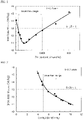
- FIG. 1 is a drawing showing the relation.
- the iron loss is confirmed to be reduced when the Zn content is in the range of 0.0005 to 0.005 mass%.
- SEM SEM-SEM
- the above steel sheet after the stress-relief annealing is subjected to an electrolytic extraction method to analyze the content N 1 (mass%) of N present as AlN in a layer within 1/20 of the sheet thickness from the one-side surface of the steel sheet and the content N 2 (mass%) of N present as AlN in the full sheet thickness of the steel sheet.
- Table 2 shows the relation of the analyzed results and the iron loss.
- FIG. 2 is a drawing showing Table 2. As seen from Table 2 and FIG.
- the reason for the reduction of the iron loss confirmed when the Zn content is in the range of 0.0005 to 0.0050 mass% is considered due to the fact that zinc-based oxide is formed on the steel sheet surface by the trace addition of zinc thus to suppress nitriding in the stress-relief annealing.
- the reason why the iron loss is rather increased as the Zn content is more increased is considered due to the fact that sulfide of Zn is formed and precipitated to increase the iron loss.
- the low iron loss can be sufficiently achieved when the Zn content is within the range of 0.0005 to 0.0050 mass%. As shown in FIGS. 1 and 2 , however, there are differences even among the low iron loss values, and in order to identify the cause of the differences, a ratio of Zn to other trace elements has been investigated. As seen from Table 3 and FIG. 3 being a drawing of Table 3, the result shows that the lower iron loss is achieved when the Zn and S contents are within a given range.
- an atomic ratio of Zn to S or (Zn /65)/(S/32) satisfies the following equation (1): 0.20 ⁇ Zn/65 / S/32 ⁇ 0.90 It is supposedly due to the fact that it is difficult to obtain the effect of suppressing nitriding by Zn in the case of 0.20 > (Zn/65)/(S/32), as compared to the case that the ratio is within the above range, while the precipitation amount of ZnS increases to rather increase the iron loss in the case of (Zn/65)/(S/32) > 0.90.
- Table 3 (Zn/65)/(S/32) Iron loss W 10/400 (W/kg) 0.12 12.4 0.19 12.1 0.23 11.6 0.35 11.0 0.47 11.1 0.59 11.5 0.89 11.8 1.17 12.7
- a JIS No. 5 tensile test specimen having a tensile direction in the rolling direction is taken out from the steel sheet after the finish annealing to thus measure an upper yield point thereof by a tensile test according to JIS Z 2241, and a value of 560 MPa is obtained.
- test specimens with a length of 180 mm and a width of 30 mm are cut out both from the rolling direction (L-direction) and the direction perpendicular to the rolling direction (C-direction) of the finish-annealed steel sheet and subjected to a heat treatment simulating a stress-relief annealing in a mixed atmosphere of hydrogen and nitrogen at 825°C for 1 hour to measure values of iron loss W 10/400 in (L+C) directions by an Epstein test.
- an experiment is conducted by varying a nitrogen partial pressure within the range of 0 to 100 vol% with the dew point (dp) of the mixed atmosphere in the stress-relief annealing of -50°C (constant), and also another experiment is conducted by varying a dew point within the range of -60 to 30°C at a nitrogen partial pressure of 20 vol% (constant) during the stress relief annealing.
- Table 4 shows a relation between the nitrogen partial pressure of the atmosphere in the stress-relief annealing and the iron loss after the stress-relief annealing. Also, FIG. 4 is a drawing of Table 4. Table 4 and FIG. 4 show that the excellent iron loss properties can be obtained when the nitrogen partial pressure of the atmosphere in the stress-relief annealing is reduced to not more than 30 vol%. This is considered due to the fact that nitriding in the surface layer of the steel sheet is suppressed by reducing the nitrogen partial pressure of the atmosphere in the stress-relief annealing to not more than 30 vol%.
- Table 4 Nitrogen partial pressure of atmosphere in stress-relief annealing (vol%) Iron loss W 10/400 (W/kg) 100 16.8 80 16.2 70 15.9 50 14.9 30 12.7 10 12.2 0 12.0
- Table 5 shows a relation between the dew point of the atmosphere in the stress-relief annealing and the iron loss after the stress-relief annealing.
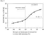
- FIG. 5 is a drawing of Table 5.
- excellent iron loss properties are obtained when the dew point of the atmosphere in the stress-relief annealing is set to not higher than -20°C. This is considered due to the fact that the formation of a layer of oxide such as Al 2 O 3 and the like is suppressed on the steel sheet surface and the increase of hysteresis loss is suppressed by setting the dew point of the atmosphere in the stress-relief annealing to not higher than -20°C.
- Table 5 Dew point of an atmosphere in stress-relief annealing (°C) Iron loss W 10/400 (W/kg) -60 12.0 -45 12.4 -30 12.8 -20 13.4 0 15.6 10 16.5 30 17.5
- C is a harmful element which forms a carbide to cause magnetic aging and thus deteriorate iron loss properties of a product sheet. Therefore, it is necessary to limit an upper limit of C contained in a raw steel material to 0.0050 mass%, preferably to not more than 0.0040 mass%. Moreover, the lower limit of C is not particularly defined, but is preferable to be about 0.0001 mass% from a viewpoint of suppressing decarburization cost in the steelmaking.
- Si has not only an effect of increasing a specific resistance of steel to reduce an iron loss but also an effect of increasing a strength of steel by solid-solution strengthening, and hence it is contained by not less than 2.8 mass%.
- the Si content exceeding 6.5 mass% makes the rolling difficult, so that the upper limit is 6.5 mass%.
- Si is in the range of 3.0 to 6.0 mass%.
- Mn is an element useful for increasing the specific resistance and strength of steel, like Si. Also, Mn forms a sulfide to thus fix S and improves hot brittleness, and hence Mn is contained by not less than 0.05 mass%. On the other hand, the addition exceeding 2.0 mass% causes slab cracking and the like and deteriorates the operability in the steel-making, and accordingly, the upper limit is set to 2.0 mass%. Preferably, Mn is in the range of 0.1 to 1.5 mass%.
- P is an element which increases the specific resistance and has a significant effect of reducing eddy current loss. As being excellent in the solid-solution strengthening ability, P can be properly added. However, the excessive addition of P causes the deterioration of the cold rolling property, so that the upper limit is 0.10 mass%, preferably not more than 0.05 mass%.
- S is formed into sulfide to form precipitates and/or inclusion and deteriorate productivity (hot-rolling property) and magnetic properties of a product sheet, so that it is preferable to decrease Si as much as possible.
- the upper limit of S is 0.0050 mass%, more preferably not more than 0.0030 mass%.
- Al has an effect of increasing the specific resistance of steel and reduce the iron loss, like Si.
- the lower limit is 0.3 mass%.
- the Al content exceeds 2 mass%, steel is embrittled and the rolling is difficult, so that the upper limit is 2 mass%.
- Al is in the range of 0.4 to 1.5 mass%.
- N is an element that forms a nitride and is precipitated to deteriorate the magnetic properties, so that the N content is limited to not more than 0.0050 mass%, preferably to not more than 0.0040 mass%.
- Zn is one of the most important components in the invention and has an effect of suppressing nitriding on the steel sheet surface in the stress-relief annealing. Accordingly, Zn is added by not less than 0.0005 mass%. On the other hand, when Zn is added by more than 0.0050 mass%, sulfide is formed and precipitated, rather causing an increase in the iron loss. Therefore, the Zn content is limited to not more than 0.0050 mass. Preferably Zn is in the range of 0.001 to 0.004 mass%.
- Ti and Nb are elements that form fine precipitates to be precipitated and increase the iron loss.
- each content exceeds 0.0030 mass%, the above bad influence becomes remarkable, so that each content of Ti and Nb is limited to not more than 0.0030 mass%, preferably not more than 0.0020 mass%.
- O is an element that forms oxide to deteriorate the magnetic properties, and thus the O content is limited to not more than 0.0050 mass%, preferably not more than 0.0040 mass%.
- the non-oriented electrical steel sheet according to the invention is preferable to have an atomic ratio of Zn to S, i.e. (Zn/65)/(S/32) satisfying the following equation (1), in addition to the above component composition: 0.20 ⁇ Zn / 65 / S / 32 ⁇ 0.90
- the atomic ratio of Zn to S satisfying the above equation (1) allows the effect of suppressing nitriding of Zn to be developed remarkably.
- the remainder other than the above components in the non-oriented electrical steel sheet according to the invention is Fe and inevitable impurities.
- the following elements may be contained in addition to the aforementioned components.
- Sn and Sb have an effect of improving recrystallization texture to improve the magnetic flux density and iron loss.
- each element it is preferable to add each element by not less than 0.005 mass%.
- the addition exceeding 0.20 mass% causes the above effect to be saturated. Therefore, it is preferable to add one or two of Sn and Sb in the range of 0.005 to 0.20 mass% each, more preferably 0.01 to 0.1 mass% each.
- Ca, Mg, and REM have an effect of forming stable sulfide and improving the grain growth properties in stress-relief annealing.
- the total addition exceeding 0.020 mass% only causes the above effect to be saturated.
- the total content is preferable to fall within the range of 0.0005 to 0.020 mass%. More preferably, it is in the range of 0.001 to 0.008 mass%.
- Cr, Co, Ni, and Cu have an effect of increasing specific resistance of steel to reduce the iron loss and increase the strength of steel.
- the addition exceeding 1.0 mass% brings about the increase in costs. Therefore, these elements are preferable to be added by 0.01 to 1.0 mass% in total, more preferably by 0.1 to 0.5 mass% in total.
- Mo and W are elements both effective for suppressing defect (scab) of the steel sheet surface.
- the steel sheet according to the invention being a high alloy steel and easily oxidized, tends to cause scab resulting from surface cracking, at a high incidence rate.
- the cracking can be suppressed by adding a trace amount of Mo and W which are elements that increase the high-temperature strength.
- Mo and W are added, therefore, each content is preferable to be in the above range. More preferably, each content is in the range of 0.0050 to 0.050 mass%.
- the non-oriented electrical steel sheet according to the invention may contain an element other than the aforementioned components in the range that has no bad influence on the strength properties and magnetic properties of the non-oriented electrical steel sheet.
- the term “has no bad influence on the strength properties” means that the yield stress after the finish annealing is not less than 480 MPa when the respective elements are contained.
- the term “have no bad influence on the magnetic properties” means that the iron loss W 10/400 (W/kg) is not less than a standard value, which is calculated by the following equation (3), when the respective elements are contained.
- the components other than the aforementioned ones include not more than 0.10 mass% As, not more than 0.10 mass% Bi and so on.
- a production of a non-oriented electrical steel sheet according to the invention comprises a series of steps comprising a production step of the aforementioned raw steel material, a hot rolling step, a hot-band annealing step, a pickling step, a cold rolling step and a finish annealing step. Each step will be concretely explained below.
- a raw steel material (slab) used in the production of a non-oriented electrical steel sheet according to the invention can be produced by melting a steel having the aforementioned component composition conforming to the invention by a well-known refining process using a converter, an electric furnace, a vacuum degassing device or the like and then performing a usual procedure of a continuous casting method or an ingot making-blooming method.
- a thin slab having a thickness of not more than 100 mm may be produced by a direct casting method.
- the steel slab is usually hot rolled by a well-known process under well-known conditions to form a hot-rolled sheet.
- the steel slab is usually reheated to a given temperature in a heating furnace and then subjected to the hot rolling, but may be subjected to the hot rolling immediately after the casting without reheating. In the case of using the thin slab, it may be hot rolled or may proceed to subsequent step without hot rolling.
- a hot-band annealing subsequent to the hot rolling is preferable to be performed at a soaking temperature in the range of 800 to 1100°C.
- the effect of the hot-band annealing is small when the soaking temperature is lower than 800°C, while, when it exceeds 1100°C, crystal grains are coarsened to promote brittle fracture (sheet breakage) in cold rolling or become disadvantageous to the production costs.
- the soaking time is preferable to be not more than 180 seconds from a viewpoint of ensuring productivity. It is more preferable that the soaking temperature is 850 to 1000°C and the soaking time is not more than 60 seconds.
- the steel sheet after the hot-band annealing is pickled for descaling and thereafter subjected to a single cold rolling or two or more cold rollings having an intermediate annealing between each cold rolling to form a cold-rolled sheet having a final sheet thickness.
- the finish thickness in the cold rolling is not particularly limited, but is preferable to be in the range of 0.1 to 0.35 mm. The productivity lowers when the sheet thickness is less than 0.1 mm, while the effect of reducing the iron loss is small when the sheet thickness exceeds 0.35 mm.
- the cold-rolled sheet having the final sheet thickness is then subjected to a finish annealing.
- the finish annealing is preferably a continuous annealing to be performed at a preferable soaking temperature of 700 to 900°C for a soaking temperature holding time of 1 to 300 seconds.
- a preferable soaking temperature 700 to 900°C for a soaking temperature holding time of 1 to 300 seconds.
- the soaking temperature is lower than 700°C and the soaking time is less than 1 second, recrystallization is not advanced sufficiently, failing to obtain not only good magnetic properties but also a sufficient effect of the shape correction in the continuous annealing.
- the soaking temperature exceeds 900°C and the soaking time exceeds 300 seconds, the crystal grain size is coarsened to decrease the strength of the steel sheet.
- the finish annealing is performed at a low temperature for a short time as much as possible within the extent the shape correction can be conducted. More preferably, the soaking temperature is in the range of 750 to 850°C and the soaking time is in the range of 1 to 30 seconds.
- the steel sheet after the finish annealing has a property that the yield stress in the tensile test (upper yield point) is not less than 480 MPa. As mentioned later, when the stress-relief annealing is conducted under conditions conforming to the present invention, the steel sheet has a feature that the iron loss properties are very excellent.
- an insulation coating on the surface of the steel sheet after the finish annealing and provide a product sheet (non-oriented electrical steel sheet).
- the insulation coating is desirably an organic coating containing a resin to secure a good punchability, while it is desirably a semi-organic coating or an inorganic coating when the weldability is considered important.
- the motor core according to the invention uses the steel sheet after the finish annealing obtained as above as a raw material, and a rotor core material and a stator core material of a core form are taken out from the steel sheet as a raw material by punching or the like at the same time. Thereafter, the rotor core material is laminated and fixed to assemble a rotor core, and the stator core material is laminated and fixed to assemble a stator core.
- the rotor core which is required to have a high strength is used in the motor core as it is, while the stator core which is required to have excellent magnetic properties is further subjected to a stress-relief annealing to improve the magnetic properties and then used in the motor core.
- This stress-relief annealing is a very important step in the invention and is preferable to be conducted under conditions at 780 to 950°C for 0.1 to 10 hours.
- the stress-relief annealing temperature is lower than 780°C and the annealing time is less than 0.1 hour, the effect of reducing the iron loss is small.
- the annealing temperature exceeds 950°C and the annealing time exceeds 10 hours it is difficult to secure insulation among the laminated steel sheets, and the productivity is hindered.
- the atmosphere in the stress-relief annealing is also very important and is an inert gas atmosphere from a viewpoint of suppressing the nitriding of the surface layer of the steel sheet.
- it is a mixed gas of one or more selected from N 2 , H 2 and a noble gas, and a N 2 content in the atmosphere gas is preferable to be not more than 30 vol%.
- the dew point of the atmosphere is preferably not higher than -20°C, more preferably not higher than -40°C from a viewpoint of preventing oxidation on the steel sheet surface to reduce the iron loss.
- the atmosphere in the stress-relief annealing is preferable to be controlled at a temperature zone of not lower than 600°C in the heating, soaking and cooling.
- the steel sheet subjected to the stress-relief annealing under the above conditions that is, the steel sheet configuring the stator core satisfies the following equation (2): (t ⁇ N 2 )/ ⁇ (t/10) ⁇ N 1 ⁇ ⁇ 5.0 .. (2), where N 1 (mass%) is a content of nitrogen present as AlN (N as AlN) in a layer from a one-side surface to 1/20 of a sheet thickness and N 2 (mass%) is a content of nitrogen present as AlN in a full sheet thickness (N as AlN) and t (mm) is a sheet thickness of the steel sheet.
- the equation (2) can be attained by controlling the Zn content in the raw material steel sheet to a range of 0.0005 to 0.0050 mass% together with controlling the nitrogen partial pressure and the dew point of the atmosphere in the stress-relief annealing to not more than 30 vol% and not higher than -20°C, respectively, to suppress the nitriding in the surface layer of the steel sheet and oxidation on the steel sheet surface.
- Each raw steel material (slab) having various component compositions shown in Table 6 is heated to a temperature of 1120°C for 30 minutes and thereafter hot rolled to form a hot-rolled sheet having a sheet thickness of 1.9 mm.
- the hot-rolled sheet is subjected to a hot-band annealing at 925°C for 30 seconds, pickled for descaling and cold rolled to form a cold-rolled sheet having a final sheet thickness shown in Table 7.
- the cold-rolled sheet is subjected to a finish annealing under various conditions shown in Table 7 to obtain a finish-annealed sheet.
- a JIS No. 5 tensile test specimen having a tensile direction in the rolling direction is taken out from the thus-obtained finish-annealed sheet, and a tensile test is conducted according to JIS Z 2241 to measure an upper yield point.
- test specimens with a length of 180 mm and a width of 30 mm are cut out from the rolling direction (L-direction) and the direction perpendicular to the rolling direction (C-direction) of the finish-annealed sheet, and subjected to a heat treatment simulating a stress-relief annealing under various conditions shown in Table 7 to measure iron loss W 10/400 in (L + C) directions by an Epstein test.
- test specimens after the stress-relief annealing is subjected to an electrolytic extraction method to measure the content N 1 (mass%) of nitrogen (N as AlN) present as AlN in a layer from one-side surface of the steel sheet to 1/20 of the sheet thickness and the content N 2 (mass%) of nitrogen (N as AlN) forming AlN in the full sheet thickness.
Landscapes
- Chemical & Material Sciences (AREA)
- Engineering & Computer Science (AREA)
- Metallurgy (AREA)
- Organic Chemistry (AREA)
- Mechanical Engineering (AREA)
- Materials Engineering (AREA)
- Physics & Mathematics (AREA)
- Thermal Sciences (AREA)
- Crystallography & Structural Chemistry (AREA)
- Electromagnetism (AREA)
- Manufacturing & Machinery (AREA)
- Power Engineering (AREA)
- Dispersion Chemistry (AREA)
- Health & Medical Sciences (AREA)
- Child & Adolescent Psychology (AREA)
- Soft Magnetic Materials (AREA)
- Manufacturing Of Steel Electrode Plates (AREA)
Abstract
Description
- This invention relates to a method for producing a non-oriented electrical steel sheet, a method for producing a motor core by using the non-oriented electrical steel sheet, and a motor core made from the non-oriented electrical steel sheet.
- With the growing demand for energy saving in electric equipment in recent years, non-oriented electrical steel sheets used in an iron core of a rotary appliance (motor core) have been required to be excellent in magnetic properties. The motor core comprises a fixed stator core and a rotating rotor core. A HEV-driven motor or the like uses a high-frequency driving power source to satisfy the recent demand for smaller size and higher output power. Therefore, a non-oriented electrical steel sheet used in a stator core is strongly demanded to have excellent magnetic properties of high magnetic flux density and low iron loss at a high frequency.
- The revolution number of the motor tends to be increased to achieve the smaller size and higher output power, so that a big centrifugal force is applied to the rotor core of a HEV-driven motor having a large outer diameter. Also, when the rotor core has a very narrow portion (1 to 2 mm) called as a bridge portion, a big load is applied to such a portion. Therefore, the non-oriented electrical steel sheet used in the rotor core is required to have a strength higher than the conventional ones.
- The non-oriented electrical steel sheet used in a motor core is desired to be excellent in magnetic properties, and moreover, it is desired to have a high strength for use in the rotor core and a high magnetic flux density and low in iron loss at a high frequency for use in the stator core.
- As mentioned above, the non-oriented electrical steel sheet is required to have different properties depending on for use in a rotor core and for use in a stator core, even when used for the same motor core. On the other hand, it is desirable to take out rotor core material and stator core material from the same raw steel sheet at the same time and thereafter assemble a rotor core or a stator core by laminating each core material, from the viewpoint of increasing the material yield and the like in the production of a motor core.
-
Patent Literature 1 discloses that a motor core is produced by taking out rotor core material and stator core material from the same raw steel sheet and laminating each material to assemble a rotor core and a stator core, and thereafter subjecting only the stator core to a stress-relief annealing. As the raw steel sheet, there is proposed a non-oriented electrical steel sheet having a sheet thickness of 0.15 to 0.35 mm, a yield strength before the stress-relief annealing of the steel sheet of not less than 600 MPa and an iron loss W10/400 after the stress-relief annealing of not more than 20 W/kg. - Patent Literature 1:
JP-A-2008-50686 - In the technique disclosed in
Patent Literature 1, however, it is necessary to reduce impurity elements (Ti, S, N, V, Nb, Zr, As) contained in the raw steel sheet to a very low level to promote crystal grain growth in the stress-relief annealing. Also, this technique has a problem that a high production cost is caused by adding Ni, being high in the raw material cost, and conducting skin pass rolling before the stress-relief annealing in order to reduce the iron loss. - The invention is made in consideration of the above problems and aims to propose a method for producing a non-oriented electrical steel sheet capable of producing a rotor core with high strength and a stator core with excellent magnetic properties after stress-relief annealing from the same raw material. Moreover, the invention aims to propose a method for producing a motor core by using the non-oriented electrical steel sheet and provide a motor core made from the non-oriented electrical steel sheet.
- The inventors have made various studies focusing on an influence of the surface nature of a raw steel sheet material upon magnetic properties of a non-oriented electrical steel sheet in order to develop a non-oriented electrical steel sheet that can achieve high strength required for a rotor core as well as excellent magnetic properties after stress-relief annealing required for a stator core. As a result, it has been found out that the iron loss properties after the stress-relief annealing are largely improved by properly adjusting a ratio of an amount of nitrogen present as AlN (N as AlN) in a surface layer of the steel sheet after the stress-relief annealing to an amount of nitrogen present as AlN (N as AlN) in a full sheet thickness. Thus, the inventors have obtained a knowledge that it is important to suppress nitriding on the raw steel sheet surface in the stress relief annealing by controlling the Zn content in the raw steel sheet to a given range in order to properly adjust the above nitrogen amount ratio, whereby the invention has been accomplished.
- The invention based on the above knowledge proposes a method for producing a non-oriented electrical steel sheet by subjecting a steel slab having a component composition comprising C: not more than 0.0050 mass%, Si: 2.8 to 6.5 mass%, Mn: 0.05 to 2.0 mass%, P: not more than 0.10 mass%, S: not more than 0.0050 mass%, Al: 0.3 to 2 mass%, N: not more than 0.0050 mass%, Zn: 0.0005 to 0.0050 mass%, Ti: not more than 0.0030 mass%, Nb: not more than 0.0030 mass%, O: not more than 0.0050 mass%, satisfying Si + Al ≥ 4 mass% and the remainder being Fe and inevitable impurities to a hot rolling, a hot-band annealing, a cold rolling and a finish annealing, in which a yield stress of the steel sheet after the finish annealing is made to not less than 480 MPa.
- The steel slab used in the method for producing a non-oriented electrical steel sheet according to the invention is characterized in that Zn and S contents satisfy the following equation (1):

- Also, the method for producing a non-oriented electrical steel sheet according to the invention is characterized in that a soaking temperature in the finish annealing is in the range of 700 to 900°C.
- Further, the steel slab used in the method for producing a non-oriented electrical steel sheet according to the invention is characterized by containing at least one group selected from the following groups A to D, in addition to the above component composition:
- Group A: one or two selected from Sn: 0.005 to 0.20 mass% and Sb: 0.005 to 0.20 mass%;
- Group B: one or more selected from Ca, Mg and REM by 0.0005 to 0.020 mass% in total;
- Group C: one or more selected from Cr, Co, Ni and Cu by 0.01 to 1.0 mass% in total; and
- Group D: one or two selected from Mo: 0.001 to 0.1 mass% and W: 0.001 to 0.1 mass%.
- Furthermore, the steel slab used in the method for producing a non-oriented electrical steel sheet according to the invention is characterized by containing another optional element within a range that does not affect the strength and magnetic properties of the non-oriented electrical steel sheet, in addition to the above component composition.
- Also, the invention proposes a method for producing a motor core comprising
- taking out rotor core material and stator core material at the same time from a non-oriented electrical steel sheet produced by any one of the aforementioned methods,
- laminating the rotor core material to form a rotor core, and
- laminating the stator core material followed by a stress-relief annealing to form a stator core, in which
- the steel sheet constituting the stator core is subjected to the stress-relief annealing so that N1, N2 and t satisfy the following equation (2):

W10/400 ≤ 8 + 20 × t .. (3), where N1 (mass%) is a content of nitrogen present as AlN (N as AlN) in a layer from a one-side surface to 1/20 of a sheet thickness and N2 (mass%) is a content of nitrogen present as AlN in a full sheet thickness (N as AlN) and t (mm) is a sheet thickness of the steel sheet. - The method for producing a motor core according to the invention is characterized in that a soaking temperature in the stress-relief annealing is in the range of 780 to 950°C, and an atmosphere in the stress-relief annealing is a mixed gas of one or two or more selected from nitrogen gas, hydrogen gas and a noble gas and has a nitrogen content of not more than 30 vol% and a dew point of not higher than -20°C.
- Furthermore, the invention is a motor core configured with
- a rotor core made of a non-oriented electrical steel sheet having a component composition comprising C: not more than 0.0050 mass%, Si: 2.8 to 6.5 mass%, Mn: 0.05 to 2.0 mass%, P: not more than 0.10 mass%, S: not more than 0.0050 mass%, Al: 0.3 to 2 mass%, N: not more than 0.0050 mass%, Zn: 0.0005 to 0.0050 mass%, Ti: not more than 0.0030 mass%, Nb: not more than 0.0030 mass%, O: not more than 0.0050 mass%, satisfying Si + Al ≥ 4 mass% and the remainder being Fe and inevitable impurities and
- a stator core made of the same non-oriented electrical steel sheet, in which
- the steel sheet constituting the rotor core has a yield stress of not less than 480 MPa;
- N1, N2 and t of the steel sheet constituting the stator core satisfy the following equation (2):
( t × N2)/{(t/10) × N1} ≥ 5.0 .. (2), where N1 (mass%) is a content of nitrogen present as AlN (N as AlN) in a layer from a one-side surface to 1/20 of a sheet thickness and N2 (mass%) is a content of nitrogen present as AlN in a full sheet thickness (N as AlN) and t (mm) is a sheet thickness of the steel sheet; and - an iron loss W10/400 (W/kg) satisfies the following equation (3) in relation to the sheet thickness t (mm):

- The non-oriented electrical steel sheet as a raw material of a motor core according to the invention is characterized in that Zn and S contents satisfy the following equation (1):

- Furthermore, the non-oriented electrical steel sheet as a raw material of a motor core according to the invention is characterized by containing at least one group selected from following Groups A to D, in addition to the above component composition:
- Group A: one or two selected from Sn: 0.005 to 0.20 mass% and Sb: 0.005 to 0.20 mass%;
- Group B: one or more selected from Ca, Mg and REM by 0.0005 to 0.020 mass% in total;
- Group C: one or more selected from Cr, Co, Ni and Cu by 0.01 to 1.0 mass% in total; and
- Group D: one or two selected from Mo: 0.001 to 0.1 mass% and W: 0.001 to 0.1 mass%.
- Also, the non-oriented electrical steel sheet as a raw material of a motor core according to the invention is characterized by containing another optional element within a range that does not affect the strength and magnetic properties of the non-oriented electrical steel sheet, in addition to the above component composition.
- The invention can produce a non-oriented electrical steel sheet being high in strength after finish annealing as well as low in iron loss after stress-relief annealing, whereby it is possible to produce a rotor core that requires high strength and a stator core that requires low iron loss from the same raw steel material sheet. Accordingly, it is possible to stably provide a motor core for hybrid electric car, electric car, cleaner, high-speed generator, compressor for air conditioner, machine tool and the like.
-
-
FIG. 1 is a graph showing an influence of a Zn content upon an iron loss W10/400 after stress-relief annealing. -
FIG. 2 is a graph showing an influence of a ratio of the nitrogen amount present as AlN in a surface layer and the nitrogen amount in a full sheet thickness of a steel sheet after stress-relief annealing upon an iron loss W10/400 after stress-relief annealing. -
FIG. 3 is a graph showing an influence of an atomic ratio of Zn and S {(Zn/65)/(S/ 32)} upon an iron loss W10/400 after stress-relief annealing. -
FIG. 4 is a graph showing an influence of a nitrogen partial pressure upon an iron loss W10/400 after stress-relief annealing. -
FIG. 5 is a graph showing of a dew point of an atmosphere in stress-relief annealing upon an iron loss W10/400 after stress-relief annealing. Description of Embodiments - An explanation will be made on experiments that have led to the invention below.
- At first, a finish-annealed steel sheet to be subjected to the measurement of mechanical properties and magnetic properties is produced by the following steps:
- 1. Continuous casting step in which 11 charges of steel having the following component composition are melted in a vacuum melting furnace and casted to form a raw steel material;
- (Component composition of steel)
- C: 0.0025 mass%, Si: 3.5 mass%, Mn: 0.7 mass%, P: 0.01 mass%, S: 0.0021 mass%, Al: 0.9 mass%, N: 0.0019 mass%, Ti: 0.0011 mass%, Nb: 0.0009 mass%, O: 0.0024 mass% and the remainder being Fe and inevitable impurities
- 2. Hot rolling step in which the raw steel material is hot rolled to form a hot-rolled sheet having a sheet thickness of 2.0 mm;
- 3. Hot-band annealing step in which the hot-rolled sheet is annealed at 930°C for 30 seconds;
- 4. Pickling step in which the hot-rolled sheet is pickled after hot-band annealing;
- 5. Cold rolling step in which the hot-rolled sheet after the pickling is formed into a cold-rolled sheet having a sheet thickness of 0.25 mm;
- 6. Finish annealing step in which the cold-rolled sheet is subjected to a finish annealing in an atmosphere of H2:N2 = 20:80 by vol% at 800°C for 10 seconds.
- A JIS No. 5 tensile test specimen having a tensile direction in the rolling direction is taken out from the steel sheet after the finish annealing and subjected to a tensile test according to JIS Z 2241 to measure an upper yield point. Moreover, other test specimens with a length of 180 mm and a width of 30 mm are cut out from both the rolling direction (L-direction) and the direction perpendicular to the rolling direction (C-direction) of the steel sheet after the finish annealing and subjected to a heat treatment simulating stress-relief annealing at 850°C for 1 hour in an atmosphere of N2 = 100 vol%, and an iron loss W10/400 thereof in (L+C directions) is measured by an Epstein test.
- The result shows that there are variations in the measurement values of the iron loss. In order to examine the cause thereof, trace components in each raw steel material (slab) are analyzed, and as a result it has been confirmed that Zn is contained in the range of 0.0001 to 0.01 mass%.
- Table 1 shows a relation between a Zn content and an iron loss W10/400 in the raw steel material, and
FIG. 1 is a drawing showing the relation. As shown in Table 1 andFIG. 1 , the iron loss is confirmed to be reduced when the Zn content is in the range of 0.0005 to 0.005 mass%. In order to study the cause of reduction of the iron loss, a section of the steel sheet after the finish annealing is observed by SEM. As a result, precipitation of fine AlN is confirmed within 1/20 of the sheet thickness from the steel sheet surface of the test specimens where iron loss has increased, and thus it is presumed that the precipitation of the fine nitride has increased the iron loss.Table 1 Zn content (mass%) Iron loss W10/400 (W/kg) 0.0001 14.1 0.0005 12.4 0.0008 12.1 0.0010 11.6 0.0015 11.0 0.0020 11.1 0.0025 11.5 0.0038 12.1 0.0050 12.7 0.0075 13.6 0.0100 15.2 - The above steel sheet after the stress-relief annealing is subjected to an electrolytic extraction method to analyze the content N1 (mass%) of N present as AlN in a layer within 1/20 of the sheet thickness from the one-side surface of the steel sheet and the content N2 (mass%) of N present as AlN in the full sheet thickness of the steel sheet. Table 2 shows the relation of the analyzed results and the iron loss.
FIG. 2 is a drawing showing Table 2. As seen from Table 2 andFIG. 2 , the iron loss is more reduced as the value of (t × N2)/{(t/10) × N1} being the ratio of the nitrogen amount present as AlN in the full sheet thickness of the steel sheet with respect to the nitrogen amount present as AlN in the layer within 1/20 of the sheet thickness from the one-side surface of the steel sheet becomes larger, that is, as the nitriding degree in the surface layer of the steel sheet is larger.Table 2 (t × N2)/{(t/10) × N1} Iron loss W10/400 (W/kg) 4.0 15.2 4.7 14.1 4.8 13.6 5.9 12.7 7.1 12.4 7.3 12.1 7.4 12.1 8.3 11.6 8.6 11.5 9.7 11.1 10.0 11.0 - From the above results, the reason for the reduction of the iron loss confirmed when the Zn content is in the range of 0.0005 to 0.0050 mass% is considered due to the fact that zinc-based oxide is formed on the steel sheet surface by the trace addition of zinc thus to suppress nitriding in the stress-relief annealing. Moreover, the reason why the iron loss is rather increased as the Zn content is more increased is considered due to the fact that sulfide of Zn is formed and precipitated to increase the iron loss.
- As mentioned above, the low iron loss can be sufficiently achieved when the Zn content is within the range of 0.0005 to 0.0050 mass%. As shown in
FIGS. 1 and 2 , however, there are differences even among the low iron loss values, and in order to identify the cause of the differences, a ratio of Zn to other trace elements has been investigated. As seen from Table 3 andFIG. 3 being a drawing of Table 3, the result shows that the lower iron loss is achieved when the Zn and S contents are within a given range. - Concretely, it is preferable that an atomic ratio of Zn to S, or (Zn /65)/(S/32) satisfies the following equation (1):

Table 3 (Zn/65)/(S/32) Iron loss W10/400 (W/kg) 0.12 12.4 0.19 12.1 0.23 11.6 0.35 11.0 0.47 11.1 0.59 11.5 0.89 11.8 1.17 12.7 - An examination is made on the influence of an atmosphere, which is considered to largely affect the nitriding in the surface layer of the steel sheet in the stress-relief annealing. In this examination, a finish-annealed steel sheet to be subjected to the measurement of mechanical properties and magnetic properties is produced by the following steps:
- 1. Continuous casting step in which 7 charges of steel having the following component composition are melted in a vacuum melting furnace and casted to form a raw steel material;
- (Component composition of steel)
- C: 0.0026 mass%, Si: 3.6 mass%, Mn: 0.5 mass%, P: 0.01 mass%, S: 0.0017 mass%, Al: 1.0 mass%, N: 0.0021 mass%, Ti: 0.0013 mass%, Nb: 0.0009 mass%, O: 0.0022 mass%, Zn: 0.0019 mass% and the remainder being Fe and inevitable impurities
- 2. Hot rolling step in which the raw steel material is hot rolled to form a hot-rolled sheet having a sheet thickness of 1.8 mm;
- 3. Hot-band annealing step in which the hot-rolled sheet is annealed at 920°C for 30 seconds;
- 4. Pickling step in which the hot-rolled sheet is pickled after the hot-band annealing;
- 5. Cold rolling step in which the hot-rolled sheet after the pickling is formed into a cold-rolled sheet having a sheet thickness of 0.30 mm;
- 6. Finish annealing step in which the cold-rolled sheet is subjected to a finish annealing in an atmosphere of H2:N2 = 20:80 by vol% at 790°C for 10 seconds.
- A JIS No. 5 tensile test specimen having a tensile direction in the rolling direction is taken out from the steel sheet after the finish annealing to thus measure an upper yield point thereof by a tensile test according to JIS Z 2241, and a value of 560 MPa is obtained. Then, test specimens with a length of 180 mm and a width of 30 mm are cut out both from the rolling direction (L-direction) and the direction perpendicular to the rolling direction (C-direction) of the finish-annealed steel sheet and subjected to a heat treatment simulating a stress-relief annealing in a mixed atmosphere of hydrogen and nitrogen at 825°C for 1 hour to measure values of iron loss W10/400 in (L+C) directions by an Epstein test. In this case, an experiment is conducted by varying a nitrogen partial pressure within the range of 0 to 100 vol% with the dew point (dp) of the mixed atmosphere in the stress-relief annealing of -50°C (constant), and also another experiment is conducted by varying a dew point within the range of -60 to 30°C at a nitrogen partial pressure of 20 vol% (constant) during the stress relief annealing.
- Table 4 shows a relation between the nitrogen partial pressure of the atmosphere in the stress-relief annealing and the iron loss after the stress-relief annealing. Also,
FIG. 4 is a drawing of Table 4. Table 4 andFIG. 4 show that the excellent iron loss properties can be obtained when the nitrogen partial pressure of the atmosphere in the stress-relief annealing is reduced to not more than 30 vol%. This is considered due to the fact that nitriding in the surface layer of the steel sheet is suppressed by reducing the nitrogen partial pressure of the atmosphere in the stress-relief annealing to not more than 30 vol%.Table 4 Nitrogen partial pressure of atmosphere in stress-relief annealing (vol%) Iron loss W10/400 (W/kg) 100 16.8 80 16.2 70 15.9 50 14.9 30 12.7 10 12.2 0 12.0 - Table 5 shows a relation between the dew point of the atmosphere in the stress-relief annealing and the iron loss after the stress-relief annealing.
FIG. 5 is a drawing of Table 5. As seen from Table 5 andFIG. 5 , excellent iron loss properties are obtained when the dew point of the atmosphere in the stress-relief annealing is set to not higher than -20°C. This is considered due to the fact that the formation of a layer of oxide such as Al2O3 and the like is suppressed on the steel sheet surface and the increase of hysteresis loss is suppressed by setting the dew point of the atmosphere in the stress-relief annealing to not higher than -20°C. - The invention is accomplished by performing further examinations based on the above knowledge.
Table 5 Dew point of an atmosphere in stress-relief annealing (°C) Iron loss W10/400 (W/kg) -60 12.0 -45 12.4 -30 12.8 -20 13.4 0 15.6 10 16.5 30 17.5 - An explanation will be made on the reason for limiting the component composition of a non-oriented electrical steel sheet according to the invention below.
- C is a harmful element which forms a carbide to cause magnetic aging and thus deteriorate iron loss properties of a product sheet. Therefore, it is necessary to limit an upper limit of C contained in a raw steel material to 0.0050 mass%, preferably to not more than 0.0040 mass%. Moreover, the lower limit of C is not particularly defined, but is preferable to be about 0.0001 mass% from a viewpoint of suppressing decarburization cost in the steelmaking.
- Si has not only an effect of increasing a specific resistance of steel to reduce an iron loss but also an effect of increasing a strength of steel by solid-solution strengthening, and hence it is contained by not less than 2.8 mass%. On the other hand, the Si content exceeding 6.5 mass% makes the rolling difficult, so that the upper limit is 6.5 mass%. Preferably, Si is in the range of 3.0 to 6.0 mass%.
- Mn is an element useful for increasing the specific resistance and strength of steel, like Si. Also, Mn forms a sulfide to thus fix S and improves hot brittleness, and hence Mn is contained by not less than 0.05 mass%. On the other hand, the addition exceeding 2.0 mass% causes slab cracking and the like and deteriorates the operability in the steel-making, and accordingly, the upper limit is set to 2.0 mass%. Preferably, Mn is in the range of 0.1 to 1.5 mass%.
- P is an element which increases the specific resistance and has a significant effect of reducing eddy current loss. As being excellent in the solid-solution strengthening ability, P can be properly added. However, the excessive addition of P causes the deterioration of the cold rolling property, so that the upper limit is 0.10 mass%, preferably not more than 0.05 mass%.
- S is formed into sulfide to form precipitates and/or inclusion and deteriorate productivity (hot-rolling property) and magnetic properties of a product sheet, so that it is preferable to decrease Si as much as possible. Hence, the upper limit of S is 0.0050 mass%, more preferably not more than 0.0030 mass%.
- Al has an effect of increasing the specific resistance of steel and reduce the iron loss, like Si. However, when Al is less than 0.3 mass%, fine nitride is formed and precipitated to deteriorate the iron loss properties, so that the lower limit is 0.3 mass%. On the other hand, when the Al content exceeds 2 mass%, steel is embrittled and the rolling is difficult, so that the upper limit is 2 mass%. Preferably, Al is in the range of 0.4 to 1.5 mass%.
- N is an element that forms a nitride and is precipitated to deteriorate the magnetic properties, so that the N content is limited to not more than 0.0050 mass%, preferably to not more than 0.0040 mass%.
- Zn is one of the most important components in the invention and has an effect of suppressing nitriding on the steel sheet surface in the stress-relief annealing. Accordingly, Zn is added by not less than 0.0005 mass%. On the other hand, when Zn is added by more than 0.0050 mass%, sulfide is formed and precipitated, rather causing an increase in the iron loss. Therefore, the Zn content is limited to not more than 0.0050 mass. Preferably Zn is in the range of 0.001 to 0.004 mass%.
- Ti and Nb are elements that form fine precipitates to be precipitated and increase the iron loss. In particular, when each content exceeds 0.0030 mass%, the above bad influence becomes remarkable, so that each content of Ti and Nb is limited to not more than 0.0030 mass%, preferably not more than 0.0020 mass%.
- O is an element that forms oxide to deteriorate the magnetic properties, and thus the O content is limited to not more than 0.0050 mass%, preferably not more than 0.0040 mass%.
- The non-oriented electrical steel sheet according to the invention is preferable to have an atomic ratio of Zn to S, i.e. (Zn/65)/(S/32) satisfying the following equation (1), in addition to the above component composition:

- The atomic ratio of Zn to S satisfying the above equation (1) allows the effect of suppressing nitriding of Zn to be developed remarkably.
- The remainder other than the above components in the non-oriented electrical steel sheet according to the invention is Fe and inevitable impurities. However, the following elements may be contained in addition to the aforementioned components.
- Sn and Sb have an effect of improving recrystallization texture to improve the magnetic flux density and iron loss. In order to obtain the above effect, it is preferable to add each element by not less than 0.005 mass%. However, the addition exceeding 0.20 mass% causes the above effect to be saturated. Therefore, it is preferable to add one or two of Sn and Sb in the range of 0.005 to 0.20 mass% each, more preferably 0.01 to 0.1 mass% each.
- Ca, Mg, and REM have an effect of forming stable sulfide and improving the grain growth properties in stress-relief annealing. In order to obtain the above effect, it is preferable to add one or more selected from these elements by not less than 0.0005 mass% in total. On the other hand, the total addition exceeding 0.020 mass% only causes the above effect to be saturated. When one or more of the elements are added, therefore, the total content is preferable to fall within the range of 0.0005 to 0.020 mass%. More preferably, it is in the range of 0.001 to 0.008 mass%.
- Cr, Co, Ni, and Cu have an effect of increasing specific resistance of steel to reduce the iron loss and increase the strength of steel. In order to obtain the above effect, it is preferable to add one or more selected from Cu, Co, Ni, and Cr by not less than 0.01 mass% in total. However, the addition exceeding 1.0 mass% brings about the increase in costs. Therefore, these elements are preferable to be added by 0.01 to 1.0 mass% in total, more preferably by 0.1 to 0.5 mass% in total.
- Mo and W are elements both effective for suppressing defect (scab) of the steel sheet surface. In particular, the steel sheet according to the invention, being a high alloy steel and easily oxidized, tends to cause scab resulting from surface cracking, at a high incidence rate. However, the cracking can be suppressed by adding a trace amount of Mo and W which are elements that increase the high-temperature strength. Such an effect is not sufficient when each content of Mo and W is less than 0.0010 mass%, while the above effect is saturated when it exceeds 0.1 mass%, only leading to increase in alloying costs. When Mo and W are added, therefore, each content is preferable to be in the above range. More preferably, each content is in the range of 0.0050 to 0.050 mass%.
- Also, the non-oriented electrical steel sheet according to the invention may contain an element other than the aforementioned components in the range that has no bad influence on the strength properties and magnetic properties of the non-oriented electrical steel sheet. The term "has no bad influence on the strength properties" means that the yield stress after the finish annealing is not less than 480 MPa when the respective elements are contained. Also, the term "have no bad influence on the magnetic properties" means that the iron loss W10/400 (W/kg) is not less than a standard value, which is calculated by the following equation (3), when the respective elements are contained. The components other than the aforementioned ones include not more than 0.10 mass% As, not more than 0.10 mass% Bi and so on.
- An explanation will be made on a method for producing a non-oriented electrical steel sheet according to the invention.
- A production of a non-oriented electrical steel sheet according to the invention comprises a series of steps comprising a production step of the aforementioned raw steel material, a hot rolling step, a hot-band annealing step, a pickling step, a cold rolling step and a finish annealing step. Each step will be concretely explained below.
- A raw steel material (slab) used in the production of a non-oriented electrical steel sheet according to the invention can be produced by melting a steel having the aforementioned component composition conforming to the invention by a well-known refining process using a converter, an electric furnace, a vacuum degassing device or the like and then performing a usual procedure of a continuous casting method or an ingot making-blooming method. Moreover, a thin slab having a thickness of not more than 100 mm may be produced by a direct casting method.
- Then, the steel slab is usually hot rolled by a well-known process under well-known conditions to form a hot-rolled sheet. Moreover, the steel slab is usually reheated to a given temperature in a heating furnace and then subjected to the hot rolling, but may be subjected to the hot rolling immediately after the casting without reheating. In the case of using the thin slab, it may be hot rolled or may proceed to subsequent step without hot rolling.
- A hot-band annealing subsequent to the hot rolling is preferable to be performed at a soaking temperature in the range of 800 to 1100°C. The effect of the hot-band annealing is small when the soaking temperature is lower than 800°C, while, when it exceeds 1100°C, crystal grains are coarsened to promote brittle fracture (sheet breakage) in cold rolling or become disadvantageous to the production costs. The soaking time is preferable to be not more than 180 seconds from a viewpoint of ensuring productivity. It is more preferable that the soaking temperature is 850 to 1000°C and the soaking time is not more than 60 seconds.
- Next, the steel sheet after the hot-band annealing is pickled for descaling and thereafter subjected to a single cold rolling or two or more cold rollings having an intermediate annealing between each cold rolling to form a cold-rolled sheet having a final sheet thickness. The finish thickness in the cold rolling (final sheet thickness) is not particularly limited, but is preferable to be in the range of 0.1 to 0.35 mm. The productivity lowers when the sheet thickness is less than 0.1 mm, while the effect of reducing the iron loss is small when the sheet thickness exceeds 0.35 mm.
- The cold-rolled sheet having the final sheet thickness is then subjected to a finish annealing. The finish annealing is preferably a continuous annealing to be performed at a preferable soaking temperature of 700 to 900°C for a soaking temperature holding time of 1 to 300 seconds. When the soaking temperature is lower than 700°C and the soaking time is less than 1 second, recrystallization is not advanced sufficiently, failing to obtain not only good magnetic properties but also a sufficient effect of the shape correction in the continuous annealing. On the other hand, when the soaking temperature exceeds 900°C and the soaking time exceeds 300 seconds, the crystal grain size is coarsened to decrease the strength of the steel sheet. From a viewpoint of securing the strength after the finish annealing required for a rotor core (yield stress: not less than 480 MPa), it is desirable that the finish annealing is performed at a low temperature for a short time as much as possible within the extent the shape correction can be conducted. More preferably, the soaking temperature is in the range of 750 to 850°C and the soaking time is in the range of 1 to 30 seconds.
- The steel sheet after the finish annealing has a property that the yield stress in the tensile test (upper yield point) is not less than 480 MPa. As mentioned later, when the stress-relief annealing is conducted under conditions conforming to the present invention, the steel sheet has a feature that the iron loss properties are very excellent.
- In order to secure the insulation property in the lamination of the steel sheets, it is preferable to form an insulation coating on the surface of the steel sheet after the finish annealing and provide a product sheet (non-oriented electrical steel sheet). The insulation coating is desirably an organic coating containing a resin to secure a good punchability, while it is desirably a semi-organic coating or an inorganic coating when the weldability is considered important.
- An explanation will be made on a motor core according to the invention and a method for producing the same below.
- The motor core according to the invention uses the steel sheet after the finish annealing obtained as above as a raw material, and a rotor core material and a stator core material of a core form are taken out from the steel sheet as a raw material by punching or the like at the same time. Thereafter, the rotor core material is laminated and fixed to assemble a rotor core, and the stator core material is laminated and fixed to assemble a stator core.
- The rotor core which is required to have a high strength is used in the motor core as it is, while the stator core which is required to have excellent magnetic properties is further subjected to a stress-relief annealing to improve the magnetic properties and then used in the motor core. This stress-relief annealing is a very important step in the invention and is preferable to be conducted under conditions at 780 to 950°C for 0.1 to 10 hours. When the stress-relief annealing temperature is lower than 780°C and the annealing time is less than 0.1 hour, the effect of reducing the iron loss is small. On the other hand, when the annealing temperature exceeds 950°C and the annealing time exceeds 10 hours, it is difficult to secure insulation among the laminated steel sheets, and the productivity is hindered.
- The atmosphere in the stress-relief annealing is also very important and is an inert gas atmosphere from a viewpoint of suppressing the nitriding of the surface layer of the steel sheet. Concretely, it is a mixed gas of one or more selected from N2, H2 and a noble gas, and a N2 content in the atmosphere gas is preferable to be not more than 30 vol%. For example, an atmosphere of H2:N2 = 80:20 as a vol% ratio is preferable. Also, the dew point of the atmosphere is preferably not higher than -20°C, more preferably not higher than -40°C from a viewpoint of preventing oxidation on the steel sheet surface to reduce the iron loss. Moreover, the atmosphere in the stress-relief annealing is preferable to be controlled at a temperature zone of not lower than 600°C in the heating, soaking and cooling.
- The steel sheet subjected to the stress-relief annealing under the above conditions, that is, the steel sheet configuring the stator core satisfies the following equation (2):
(t × N2)/{(t/10) × N1} ≥ 5.0 .. (2), where N1 (mass%) is a content of nitrogen present as AlN (N as AlN) in a layer from a one-side surface to 1/20 of a sheet thickness and N2 (mass%) is a content of nitrogen present as AlN in a full sheet thickness (N as AlN) and t (mm) is a sheet thickness of the steel sheet. - The equation (2) can be attained by controlling the Zn content in the raw material steel sheet to a range of 0.0005 to 0.0050 mass% together with controlling the nitrogen partial pressure and the dew point of the atmosphere in the stress-relief annealing to not more than 30 vol% and not higher than -20°C, respectively, to suppress the nitriding in the surface layer of the steel sheet and oxidation on the steel sheet surface.
- In the steel sheet that satisfies the equation (2), hysteresis loss can be largely decreased by suppressing nitriding in the surface layer of the steel sheet and the oxidation on the steel sheet surface in the stress-relief annealing, and thus the iron loss W10/400 (W/kg) of the steel sheet after the stress-relief annealing satisfies the following equation (3) in relation to the sheet thickness t (mm):

- Each raw steel material (slab) having various component compositions shown in Table 6 is heated to a temperature of 1120°C for 30 minutes and thereafter hot rolled to form a hot-rolled sheet having a sheet thickness of 1.9 mm. The hot-rolled sheet is subjected to a hot-band annealing at 925°C for 30 seconds, pickled for descaling and cold rolled to form a cold-rolled sheet having a final sheet thickness shown in Table 7. Then, the cold-rolled sheet is subjected to a finish annealing under various conditions shown in Table 7 to obtain a finish-annealed sheet.
Table 6-1 Steel Nº Component composition (mass%) (Zn/65) / (S/32) Remarks C Si Mn P S Al Zn Ti Nb O N Sn, Sb Ca, Mg, REM Cr, Co, Ni, Cu Mo, W 1 0.0025 3.6 0.4 0.01 0.0018 0.8 0.0021 0.0011 0.0009 0.0024 0.0027 Sn:0.03 - - - 0.57 Inventive Steel 2 0.0025 3.6 0.4 0.01 0.0018 0.8 0.0021 0.0011 0.0009 0.0024 0.0027 Sn:0.03 - - - 0.57 Inventive Steel 3 0.0025 3.6 0.4 0.01 0.0018 0.8 0.0021 0.0011 0.0009 0.0024 0.0027 Sn:0.03 - - - 0.57 Inventive Steel 4 0.0025 3.6 0.4 0.01 0.0018 0.8 0.0021 0.0011 0.0009 0.0024 0.0027 Sn:0.03 - - - 0.57 Inventive Steel 5 0.0025 3.6 0.4 0.01 0.0018 0.8 0.0003 0.0011 0.0009 0.0024 0.0027 Sn:0.03 - - - 0.08 Comparative Steel 6 0.0025 3.8 0.5 0.01 0.0019 0.6 0.0029 0.0013 0.0011 0.0025 0.0024 - - - - 0.75 Inventive Steel 7 0.0021 3.8 0.5 0.01 0.0019 0.6 0.0029 0.0013 0.0011 0.0025 0.0024 - - - - 0.75 Inventive Steel 8 0.0021 3.8 0.5 0.01 0.0019 0.6 0.0029 0.0013 0.0011 0.0025 0.0024 - - - - 0.75 Inventive Steel 9 0.0021 3.8 0.5 0.01 0.0019 0.6 0.0029 0.0013 0.0011 0.0025 0.0024 - - - - 0.75 Inventive Steel 10 0.0021 3.8 0.5 0.01 0.0019 0.6 0.0029 0.0013 0.0011 0.0025 0.0024 - - - - 0.75 Inventive Steel 11 0.0021 3.8 0.5 0.01 0.0019 0.6 0.0029 0.0013 0.0011 0.0025 0.0024 - - - - 0.75 Inventive Steel 12 0.0028 3.2 0.8 0.01 0.0024 1.2 0.0024 0.0008 0.0012 0.0021 0.0019 Sn:0.04 - - - 0.49 Inventive Steel 13 0.0028 3.2 0.8 0.01 0.0024 1.8 0.0024 0.0008 0.0012 0.0021 0.0020 Sn:0.04 - - - 0.49 Inventive Steel 14 0.0029 3.5 2.5 0.01 0.0024 0.5 0.0021 0.0008 0.0011 0.0021 0.0028 - - - - 0.43 Comparative Steel 15 0.0025 3.3 0.1 0.01 0.0024 2.5 0.0015 0.0008 0.0011 0.0021 0.0021 - - - - 0.31 Comparative Steel 16 0.0019 4.2 0.3 0.01 0.0015 0.3 0.0026 0.0014 0.0012 0.0019 0.0027 Sb:0.01 - - 0.85 Inventive Steel 17 0.0019 5.6 0.3 0.01 0.0015 0.3 0.0027 0.0014 0.0012 0.0019 0.0027 - - - - 0.89 Inventive Steel 18 0.0022 7.2 0.2 0.01 0.0024 0.3 0.0038 0.0008 0.0011 0.0021 0.0028 - - - - 0.78 Comparative Steel 19 0.0021 4.0 0.4 0.01 0.0026 0.6 0.0032 0.0011 0.0013 0.0028 0.0024 Sn:0.03 - - - 0.61 Inventive Steel 20 0.0021 4.1 0.4 0.01 0.0026 0.6 0.0032 0.0011 0.0013 0.0028 0.0024 Sn:0.03 - - - 0.61 Inventive Steel 21 0.0026 3.2 0.1 0.25 0.0026 1.5 0.0025 0.0011 0.0013 0.0028 0.0024 Sn:0.06 - - - 0.47 Comparative Steel 22 0.0024 3.4 1.2 0.01 0.0019 0.9 0.0024 0.0016 0.0014 0.0027 0.0021 Sn:0.03 - - - 0.62 Inventive Steel 23 0.0024 3.3 1.8 0.01 0.0019 0.7 0.0024 0.0016 0.0014 0.0027 0.0021 Sn:0.03 - - - 0.62 Inventive Steel 24 0.0018 3.5 0.2 0.01 0.0015 0.9 0.0021 0.0012 0.0009 0.0027 0.0021 Sb:0.05 - - - 0.69 Inventive Steel Table 6-2 Steel Nº Component composition (mass%) (Zn/65) / (S/32) Remarks C Si Mn P S Al Zn Ti Nb O N Sn, Sb Ca, Mg, REM Cr, Co, Ni, Cu Mo, W 25 0.0017 3.6 0.5 0.01 0.0024 0.8 0.0027 0.0016 0.0014 0.0027 0.0021 - Ca:0.0034 - - 0.55 Inventive Steel 26 0.0017 3.6 0.5 0.01 0.0026 0.8 0.0027 0.0016 0.0014 0.0027 0.0021 - Mg:0.0025 - 0.51 Inventive Steel 27 0.0017 3.6 0.5 0.01 0.0027 0.8 0.0027 0.0016 0.0014 0.0027 0.0021 - REM:0.0072 - - 0.49 Inventive Steel 28 0.0025 3.3 0.6 0.01 0.0059 0.9 0.0019 0.0018 0.0013 0.0029 0.0026 Sn:0.04 - - - 0.16 Comparative Steel 29 0.0025 3.8 0.2 0.01 0.0015 0.5 0.0021 0.0041 0.0013 0.0029 0.0026 Sn:0.04 - - - 0.69 Comparative Steel 30 0.0025 3.8 0.2 0.01 0.0015 0.5 0.0021 0.0007 0.0038 0.0029 0.0026 Sn:0.04 - - - 0.69 Comparative Steel 31 0.0025 3.8 0.2 0.01 0.0015 0.5 0.0021 0.0007 0.0011 0.0064 0.0026 Sn:0.04 - - - 0.69 Comparative Steel 32 0.0025 3.8 0.2 0.01 0.0015 0.5 0.0021 0.0007 0.0011 0.0021 0.0065 Sn:0.04 - - - 0.69 Comparative Steel 33 0.0021 4.1 0.5 0.01 0.0023 0.7 0.0024 0.0012 0.0013 0.0023 0.0022 Sn:0.03 - - - 0.51 Inventive Steel 34 0.0021 4.1 0.5 0.01 0.0023 0.7 0.0024 0.0012 0.0013 0.0023 0.0022 Sn:0.03 - - - 0.51 Inventive Steel 35 0.0021 4.1 0.5 0.01 0.0023 0.7 0.0024 0.0012 0.0013 0.0023 0.0022 Sn:0.03 - - - 0.51 Inventive Steel 36 0.0026 3.4 0.9 0.01 0.0026 1.4 0.0019 0.0018 0.0012 0.0021 0.0023 Sn:0.03 - - - 0.36 Inventive Steel 37 0.0026 3.4 0.9 0.01 0.0026 1.4 0.0019 0.0018 0.0012 0.0021 0.0023 Sn:0.03 - - - 0.36 Inventive Steel 38 0.0026 3.4 0.9 0.01 0.0026 1.4 0.0019 0.0018 0.0012 0.0021 0.0023 Sn:0.03 - - - 0.36 Inventive Steel 39 0.0025 3.7 0.8 0.01 0.0021 0.8 0.0021 0.0013 0.0013 0.0032 0.0031 Sn:0.03 Ca:0.0029 - - 0.49 Inventive Steel 40 0.0024 2.9 0.8 0.008 0.0026 1.6 0.0034 0.0016 0.0011 0.0028 0.0021 Sn:0.03 - - - 0.64 Inventive Steel 41 0.0024 3.4 0.6 0.005 0.0021 0.9 0.0024 0.0014 0.0014 0.0021 0.0025 Sn:0.01 - - - 0.56 Inventive Steel 42 0.0024 3.6 0.4 0.01 0.0018 0.9 0.0045 0.0014 0.0014 0.0021 0.0025 Sn:0.04 - - - 1.23 Inventive Steel 43 0.0029 3.5 0.3 0.09 0.0019 1.2 0.0021 0.0011 0.0009 0.0025 0.0024 Sn:0.03 - - - 0.54 Inventive Steel 44 0.0028 3.5 0.3 0.11 0.0019 1.2 0.0022 0.0011 0.0009 0.0025 0.0024 Sn:0.03 - - - 0.57 Comparative Steel 45 0.0025 3.6 0.4 0.01 0.0018 0.8 0.0007 0.0011 0.0009 0.0024 0.0027 Sn:0.03 - - - 0.19 Inventive Steel 46 0.0025 3.6 0.4 0.01 0.0037 0.8 0.0013 0.0011 0.0009 0.0024 0.0027 Sn:0.03 - - - 0.17 Inventive Steel 47 0.0025 3.6 0.4 0.01 0.0018 0.8 0.0041 0.0011 0.0009 0.0024 0.0027 Sn:0.03 - - - 1.12 Inventive Steel 48 0.0025 3.6 0.4 0.01 0.0010 0.8 0.0021 0.0011 0.0009 0.0024 0.0027 Sn:0.03 - - - 1.03 Inventive Steel Table 6-3 Steel Nº Component composition (mass%) (Zn/65) / (S/32) Remarks C Si Mn P S Al Zn Ti Nb O N Sn, Sb Ca, Mg, REM Cr, Co, Ni, Cu Mo, W 49 0.0021 3.8 0.5 0.01 0.0019 0.6 0.0029 0.0013 0.0011 0.0025 0.0024 - - Cr:0.05 - 0.75 Inventive Steel 50 0.0021 3.8 0.5 0.01 0.0019 0.6 0.0029 0.0013 0.0011 0.0025 0.0024 - - Cr:0.1 - 0.75 Inventive Steel 51 0.0021 3.8 0.5 0.01 0.0019 0.6 0.0029 0.0013 0.0011 0.0025 0.0024 - - Cr:0.5 - 0.75 Inventive Steel 52 0.0021 3.8 0.5 0.01 0.0019 0.6 0.0029 0.0013 0.0011 0.0025 0.0024 - - Cr:0.9 - 0.75 Inventive Steel 53 0.0025 3.6 0.4 0.01 0.0018 0.8 0.0021 0.0011 0.0009 0.0024 0.0027 - - Co:0.05 - 0.57 Inventive Steel 54 0.0025 3.6 0.4 0.01 0.0018 0.8 0.0021 0.0011 0.0009 0.0024 0.0027 - - Co:0.1 - 0.57 Inventive Steel 55 0.0025 3.6 0.4 0.01 0.0018 0.8 0.0021 0.0011 0.0009 0.0024 0.0027 - - Co:0.5 - 0.57 Inventive Steel 56 0.0025 3.6 0.4 0.01 0.0018 0.8 0.0021 0.0011 0.0009 0.0024 0.0027 - - Co:0.9 - 0.57 Inventive Steel 57 0.0028 3.2 0.8 0.01 0.0024 1.8 0.0024 0.0008 0.0012 0.0021 0.0020 - - Ni:0.05 - 0.49 Inventive Steel 58 0.0028 3.2 0.8 0.01 0.0024 1.8 0.0024 0.0008 0.0012 0.0021 0.0020 - - Ni:0.1 - 0.49 Inventive Steel 59 0.0028 3.2 0.8 0.01 0.0024 1.8 0.0024 0.0008 0.0012 0.0021 0.0020 - - Ni:0.5 - 0.49 Inventive Steel 60 0.0028 3.2 0.8 0.01 0.0024 1.8 0.0024 0.0008 0.0012 0.0021 0.0020 - - Ni:0.9 - 0.49 Inventive Steel 61 0.0029 3.5 0.3 0.09 0.0019 1.2 0.0021 0.0011 0.0009 0.0025 0.0024 - - Cu:0.05 - 0.54 Inventive Steel 62 0.0029 3.5 0.3 0.09 0.0019 1.2 0.0021 0.0011 0.0009 0.0025 0.0024 - - Cu:0.1 - 0.54 Inventive Steel 63 0.0029 3.5 0.3 0.09 0.0019 1.2 0.0021 0.0011 0.0009 0.0025 0.0024 - - Cu:0.5 - 0.54 Inventive Steel 64 0.0029 3.5 0.3 0.09 0.0019 1.2 0.0021 0.0011 0.0009 0.0025 0.0024 - - Cu:0.05 - 0.54 Inventive Steel 65 0.0021 3.8 0.5 0.01 0.0019 0.6 0.0029 0.0013 0.0011 0.0025 0.0024 - - Cr:0.3, Ni:0.3 - 0.75 Inventive Steel 66 0.0025 3.6 0.4 0.01 0.0018 0.8 0.0021 0.0011 0.0009 0.0024 0.0027 - - Co:0.3, Cu:0.3 - 0.57 Inventive Steel 67 0.0025 3.6 0.4 0.01 0.0018 0.8 0.0021 0.0011 0.0009 0.0024 0.0027 - - Ni:0.3, Cu:0.3 - 0.57 Inventive Steel 68 0.0025 3.6 0.4 0.01 0.0018 0.8 0.0021 0.0011 0.0009 0.0024 0.0027 - - Cr:0.3, Cu:0.3 - 0.57 Inventive Steel 69 0.0021 3.8 0.5 0.01 0.0019 0.6 0.0029 0.0013 0.0011 0.0025 0.0024 - - - Mo:0.0025 0.75 Inventive Steel 70 0.0021 3.8 0.5 0.01 0.0019 0.6 0.0029 0.0013 0.0011 0.0025 0.0024 - - - Mo:0.05 0.75 Inventive Steel 71 0.0021 3.8 0.5 0.01 0.0019 0.6 0.0029 0.0013 0.0011 0.0025 0.0024 - - - W:0.0025 0.75 Inventive Steel 72 0.0021 3.8 0.5 0.01 0.0019 0.6 0.0029 0.0013 0.0011 0.0025 0.0024 - - - W:0.05 0.75 Inventive Steel - A JIS No. 5 tensile test specimen having a tensile direction in the rolling direction is taken out from the thus-obtained finish-annealed sheet, and a tensile test is conducted according to JIS Z 2241 to measure an upper yield point.
- Also, test specimens with a length of 180 mm and a width of 30 mm are cut out from the rolling direction (L-direction) and the direction perpendicular to the rolling direction (C-direction) of the finish-annealed sheet, and subjected to a heat treatment simulating a stress-relief annealing under various conditions shown in Table 7 to measure iron loss W10/400 in (L + C) directions by an Epstein test.
- Furthermore, the test specimens after the stress-relief annealing is subjected to an electrolytic extraction method to measure the content N1 (mass%) of nitrogen (N as AlN) present as AlN in a layer from one-side surface of the steel sheet to 1/20 of the sheet thickness and the content N2 (mass%) of nitrogen (N as AlN) forming AlN in the full sheet thickness.
- The measurement results are also shown in Table 7. As seen from these results, all the steel sheets that are produced by the raw steel materials having the component compositions conforming to the invention under the conditions conforming to the invention have a yield stress after the finish annealing of not less than 480 MPa and such excellent iron loss properties that the iron loss W10/400 after the stress-relief annealing satisfies the above equation (3) of the invention.
Table 7-1 Steel No. Final sheet thickne ss t (mm) Finish annealing Yield stress after finish annealing (MPa) Stress-relief annealing N as AlN in steel Iron loss after stress-relief annealing W10/400 (W/kg) Value in right side of equation (1) Remarks Temp. (°C) Time (sec) Temp. (°C) Time (hr) Atmosphere gas (vol%) Dew point (°C) 1/20 layer Ni (mass%) Full sheet thickne ss N2 (mass%) Ratio of precipitated nitrogen amount ∗1 1 0.25 800 10 550 850 1 N2:H2=20:80 -55 0.0032 0.0026 8.1 10.6 13.0 Inventive Example 2 0.30 800 10 550 850 1 N2:H2=20:80 -55 0.0029 0.0027 9.3 12.6 14.0 Inventive Example 3 0.20 800 10 550 850 1 N2:H2=20:80 -55 0.0035 0.0028 8.0 10.0 12.0 Inventive Example 4 0.15 800 10 550 850 1 N2:H2=20:80 -55 0.0037 0.0029 7.8 8.8 11.0 Inventive Example 5 0.25 800 10 550 850 1 N2:H2=20:80 -55 0.0061 0.0029 4.8 14.5 13.0 Comparative Example 6 0.25 800 10 550 850 1 N2=100 -50 0.0082 0.0031 3.8 15.3 13.0 Comparative Example 7 0.25 780 10 565 825 1 H2=100 -50 0.0024 0.0024 10.0 10.9 13.0 Inventive Example 8 0.20 780 10 565 825 1 Ar=100 -50 0.0024 0.0024 10.0 9.7 12.0 Inventive Example 9 0.25 780 10 565 825 1 H2=100 -8 0.0071 0.0029 4.1 14.8 13.0 Comparative Example 10 0.25 1000 10 450 825 2 H2=100 -50 0.0068 0.0029 4.3 11.2 13.0 Inventive Example 11 0.25 750 10 585 800 2 H2:Ar=20:80 -60 0.0024 0.0024 10.0 10.9 13.0 Inventive Example 12 0.27 760 10 535 825 1 H2:Ar=20:80 -50 0.0019 0.0019 10.0 11.2 13.4 Inventive Example 13 0.25 810 10 580 825 1 H2:Ar=20:80 -50 0.0020 0.0020 10.0 10.9 13.0 Inventive Example 14 Unable to produce due to slab cracking - - - - - - - - - Comparative Example 15 Unable to produce due to slab cracking - - - - - - - - - Comparative Example 16 0.25 850 10 570 900 1 H2=100 -45 0.0027 0.0027 10.0 9.9 13.0 Inventive Example 17 0.25 880 10 600 900 1 H2=100 -45 0.0027 0.0027 10.0 9.1 13.0 Inventive Example 18 Unable to produce due to slab cracking - - - - - - - - - Comparative Example 19 0.30 820 10 580 825 1 N2:H2=10:90 -50 0.0026 0.0024 9.2 11.9 14.0 Inventive Example 20 0.20 820 10 595 825 1 N2:H2=10:90 -50 0.0026 0.0024 9.2 9.2 12.0 Inventive Example 21 Unable to produce due to sheet breakage in cold rolling - - - - - - - - - Comparative Example 22 0.25 810 10 550 850 1 N2:H2=20:80 -55 0.0024 0.0021 8.8 11.0 13.0 Inventive Example 23 0.25 810 10 560 850 1 N2:H2=20:80 -55 0.0025 0.0022 8.8 10.8 13.0 Inventive Example 24 0.27 790 10 530 825 1 N2:H2=10:90 -58 0.0025 0.0022 8.8 11.1 13.4 Inventive Example ∗1: (t × N2)/{(t/10) × N1} = 10 × (N2/N1) Table 7-2 Steel No. Final sheet thickne ss t (mm) Finish annealing Yield stress after finish annealing (MPa) Stress-relief annealing N as AlN in steel Iron loss after stress-relief annealing W 10/400 (W/kg) Value in right side of equation (1) Remarks Tem. (°C) Time (sec) Temp. (°C) Time (hr) Atmosphere gas (vol%) Dew point (°C) 1/20 layer N1 (mass%) Full sheet thickne ss N2 (mass%) Ratio of precipitated nitrogen amount ∗ 1 25 0.25 790 10 540 825 1 N2:H2=10:90 -60 0.0023 0.0021 9.1 10.3 13.0 Inventive Example 26 0.25 790 10 540 825 1 N2:H2=10:90 -60 0.0023 0.0021 9.1 10.3 13.0 Inventive Example 27 0.25 790 10 540 825 1 N2:H2=10:90 -60 0.0023 0.0021 9.1 10.3 13.0 Inventive Example 28 0.25 820 10 520 820 1 N2:H2=20:80 -50 0.0027 0.0026 9.6 14.8 13.0 Comparative Example 29 0.25 820 10 545 820 1 N2:H2=20:80 -50 0.0031 0.0027 8.7 16.1 13.0 Comparative Example 30 0.25 820 10 545 820 1 N2:H2=20:80 -50 0.0035 0.0027 7.7 15.6 13.0 Comparative Example 31 0.25 820 10 545 820 1 N2:H2=20:80 -50 0.0036 0.0027 7.5 15.3 13.0 Comparative Example 32 0.25 820 10 545 820 1 N2:H2=20:80 -50 0.0081 0.0027 3.3 17.1 13.0 Comparative Example 33 0.20 800 10 595 830 1 Ar=100 -54 0.0022 0.0022 10.0 9.0 12.0 Inventive Example 34 0.25 800 10 595 830 1 H2:Ar=20:80 -54 0.0025 0.0022 8.8 10.2 13.0 Inventive Example 35 0.30 800 10 595 830 1 N2:H2=20:80 -54 0.0024 0.0022 9.2 11.5 14.0 Inventive Example 36 0.15 800 10 585 830 1 N2:H2=20:80 -59 0.0026 0.0022 8.5 8.5 11.0 Inventive Example 37 0.20 800 10 585 900 0.5 Ar=100 -60 0.0023 0.0023 10.0 9.2 12.0 Inventive Example 38 0.25 800 10 585 850 1 N2:H2=10:90 -55 0.0024 0.0023 9.6 10.4 13.0 Inventive Example 39 0.25 800 10 580 850 2 H2:Ar=10:90 -55 0.0031 0.0031 10.0 10.5 13.0 Inventive Example 40 0.25 800 10 525 850 1 Ar=100 -50 0.0027 0.0021 7.8 10.9 13.0 Inventive Example 41 0.25 800 10 540 825 1 Ar=100 -55 0.0028 0.0025 8.9 10.8 13.0 Inventive Example 42 0.25 800 10 555 850 1 Ar=100 -55 0.0026 0.0025 9.6 12.7 13.0 Inventive Example 43 0.25 800 10 560 850 1 Ar=100 -55 0.0026 0.0024 9.2 10.5 13.0 Inventive Example 44 Unable to produce due to sheet breakage in cold rolling - - - - - - - - - Comparative Example 45 0.25 800 10 550 850 1 N2:H2=20:80 -55 0.0038 0.0026 6.8 12.8 13.0 Inventive Example 46 0.25 800 10 550 850 1 N2:H2=20:80 -55 0.0038 0.0026 6.8 12.4 13.0 Inventive Example 47 0.25 800 10 550 850 1 N2:H2=20:80 -55 0.0032 0.0026 8.1 12.7 13.0 Inventive Example 48 0.25 800 10 550 850 1 N2:H2=20:80 -55 0.0032 0.0026 8.1 12.1 13.0 Inventive Example ∗1: (t × N2)/{(t/10) × N1} = 10 × (N2/N1) Table 7-3 Steel No. Final sheet thickne ss t (mm) Finish annealing Yield stress after finish annealing (MPa) Stress-relief annealing N as AlN in steel Iron loss after stress-relief annealing W 10/400 (W/kg) Value in right side of equation (1) Remarks Temp. (°C) Time (sec) Temp. (°C) Time (hr) Atmosphere gas (vol%) Dew point (°C) 1/20 layer N1 (mass%) Full sheet thickness N2 (mass%) Ratio of precipitated nitrogen amount ∗ 1 49 0.25 780 10 568 825 1 H2=100 -50 0.0024 0.0024 10.0 10.8 13.0 Inventive Example 50 0.25 780 10 570 825 1 H2=100 -50 0.0024 0.0024 10.0 10.7 13.0 Inventive Example 51 0.25 780 10 575 825 1 H2=100 -50 0.0024 0.0024 10.0 10.7 13.0 Inventive Example 52 0.25 780 10 578 825 1 H2=100 -50 0.0024 0.0024 10.0 10.6 13.0 Inventive Example 53 0.30 800 10 552 850 1 N2:H2=20:80 -55 0.0029 0.0027 9.3 12.5 14.0 Inventive Example 54 0.30 800 10 555 850 1 N2:H2=20:80 -55 0.0029 0.0027 9.3 12.4 14.0 Inventive Example 55 0.30 800 10 557 850 1 N2:H2=20:80 -55 0.0029 0.0027 9.3 12.3 14.0 Inventive Example 56 0.30 800 10 560 850 1 N2:H2=20:80 -55 0.0029 0.0027 9.3 12.3 14.0 Inventive Example 57 0.25 810 10 585 825 1 H2:Ar=20:80 -50 0.0020 0.0020 10.0 10.8 13.0 Inventive Example 58 0.25 810 10 590 825 1 H2:Ar=20:80 -50 0.0020 0.0020 10.0 10.7 13.0 Inventive Example 59 0.25 810 10 600 825 1 H2:Ar=20:80 -50 0.0020 0.0020 10.0 10.6 13.0 Inventive Example 60 0.25 810 10 605 825 1 H2:Ar=20:80 -50 0.0020 0.0020 10.0 10.5 13.0 Inventive Example 61 0.25 800 10 560 850 1 Ar=100 -55 0.0026 0.0024 9.2 10.4 13.0 Inventive Example 62 0.25 800 10 562 850 1 Ar=100 -55 0.0026 0.0024 9.2 10.4 13.0 Inventive Example 63 0.25 800 10 565 850 1 Ar=100 -55 0.0026 0.0024 9.2 10.3 13.0 Inventive Example 64 0.25 800 10 570 850 1 Ar=100 -55 0.0026 0.0024 9.2 10.3 13.0 Inventive Example 65 0.25 780 10 575 825 1 H2=100 -50 0.0024 0.0024 10.0 10.6 13.0 Inventive Example 66 0.30 800 10 560 850 1 N2:H2=20:80 -55 0.0029 0.0027 9.3 12.3 14.0 Inventive Example 67 0.30 800 10 565 850 1 N2:H2=20:80 -55 0.0029 0.0027 9.3 12.3 14.0 Inventive Example 68 0.30 800 10 560 850 1 N2:H2=20:80 -55 0.0029 0.0027 9.3 12.3 14.0 Inventive Example 69 0.25 780 10 565 825 1 H2=100 -50 0.0024 0.0024 10.0 10.8 13.0 Inventive Example 70 0.25 780 10 565 825 1 H2=100 -50 0.0024 0.0024 10.0 10.8 13.0 Inventive Example 71 0.25 780 10 565 825 1 H2=100 -50 0.0024 0.0024 10.0 10.8 13.0 Inventive Example 72 0.25 780 10 565 825 1 H2=100 -50 0.0024 0.0024 10.0 10.8 13.0 Inventive Example ∗1: (t × N2)/{(t/10) × N1} = 10 × (N2/N1)
Claims (11)
- A method for producing a non-oriented electrical steel sheet comprisingsubjecting a steel slab having a component composition comprising C: not more than 0.0050 mass%, Si: 2.8 to 6.5 mass%, Mn: 0.05 to 2.0 mass%, P: not more than 0.10 mass%, S: not more than 0.0050 mass%, Al: 0.3 to 2 mass%, N: not more than 0.0050 mass%, Zn: 0.0005 to 0.0050 mass%, Ti: not more than 0.0030 mass%, Nb: not more than 0.0030 mass%, O: not more than 0.0050 mass%, satisfying Si + Al ≥ 4 mass% and the remainder being Fe and inevitable impurities to a hot rolling, a hot band annealing, a cold rolling and a finish annealing, characterized in thata yield stress of the steel sheet after the finish annealing is made to not less than 480 MPa.
- The method for producing a non-oriented electrical steel sheet according to claim 1, wherein
the steel slab has Zn and S contents that satisfy the following equation (1):
- The method for producing a non-oriented electrical steel sheet according to claim 1 or 2, wherein
a soaking temperature in the finish annealing is in the range of 700 to 900°C. - The method for producing a non-oriented electrical steel sheet according to any one of claims 1 to 3, wherein
the steel slab contains at least one group selected from the following Groups A to D, in addition to the above component composition:Group A: one or two selected from Sn: 0.005 to 0.20 mass% and Sb: 0.005 to 0.20 mass%;Group B: one or more selected from Ca, Mg and REM by 0.0005 to 0.020 mass% in total;Group C: one or more selected from Cr, Co, Ni and Cu by 0.01 to 1.0 mass% in total of; andGroup D: one or two selected from Mo: 0.001 to 0.1 mass% and W: 0.001 to 0.1 mass%. - The method for producing a non-oriented electrical steel sheet according to any one of claims 1 to 4, wherein
the steel slab contains another optional element within a range that does not affect the strength and magnetic properties of the non-oriented electrical steel sheet, in addition to the above component composition. - A method for producing a motor core comprisingtaking out a rotor core material and a stator core material at the same time from a non-oriented electrical steel sheet produced by the method according to any one of claims 1 to 5,laminating the rotor core material to form a rotor core, andlaminating the stator core material followed by a stress-relief annealing to form a stator core, characterized in thatthe steel sheet constituting the stator core is subjected to the stress-relief annealing so that N1, N2 and t satisfy the following equation (2):

W10/400 ≤ 8 + 20 × t .. (3), where N1 (mass%) is a content of nitrogen present as AlN (N as AlN) in a layer from a one-side surface to 1/20 of a sheet thickness and N2 (mass%) is a content of nitrogen present as AlN in a full sheet thickness (N as AlN) and t (mm) is a sheet thickness of the steel sheet. - The method for producing a motor core according to claim 6, wherein
a soaking temperature in the stress-relief annealing is in the range of 780 to 950°C and an atmosphere in the stress-relief annealing is a mixed gas of one or more selected from nitrogen gas, hydrogen gas and a noble gas and has a nitrogen content of not more than 30 vol% and a dew point of not higher than -20°C. - A motor core constituted witha rotor core made of a non-oriented electrical steel sheet having a component composition comprising C: not more than 0.0050 mass%, Si: 2.8 to 6.5 mass%, Mn: 0.05 to 2.0 mass%, P: not more than 0.10 mass%, S: not more than 0.0050 mass%, Al: 0.3 to 2 mass%, N: not more than 0.0050 mass%, Zn: 0.0005 to 0.0050 mass%, Ti: not more than 0.0030 mass%, Nb: not more than 0.0030 mass%, O: not more than 0.0050 mass%, satisfying Si + Al ≥ 4 mass% and the remainder being Fe and inevitable impurities anda stator core made of the same non-oriented electrical steel sheet, characterized in thatthe steel sheet constituting the rotor core has a yield stress of not less than 480 MPa;N1, N2 and t in the steel sheet constituting the stator core satisfy the following equation (2):(t× N2)/{(t/10) × N1} ≥ 5.0 .. (2), where N1 (mass%) is a content of nitrogen present as AlN (N as AlN) in a layer from a one-side surface to 1/20 of a sheet thickness and N2 (mass%) is a content of nitrogen present as AlN in a full sheet thickness (N as AlN) and t (mm) is a sheet thickness of the steel sheet; andan iron loss W10/400 (W/kg) satisfies the following equation (3) in relation to the sheet thickness t (mm):

- The motor core according to claim 8, wherein the non-oriented electrical steel sheet has Zn and S contents satisfying the following equation (1):

- The motor core according to claim 8 or 9, wherein
the non-oriented electrical steel sheet contains at least one group selected from following Groups A to D in addition to the above component composition:Group A: one or two selected from Sn: 0.005 to 0.20 mass% and Sb: 0.005 to 0.20 mass%;Group B: one or more selected from Ca, Mg and REM by 0.0005 to 0.020 mass% in total;Group C: one or more selected from Cr, Co, Ni and Cu by 0.01 to 1.0 mass% in total; andGroup D: one or two selected from Mo: 0.001 to 0.1 mass% and W: 0.001 to 0.1 mass%. - The motor core according to any one of claims 8 to 10, wherein
the non-oriented electrical steel sheet contains another optional element within a range that does not affect the strength and magnetic properties of the non-oriented electrical steel sheet, in addition to the above component composition.
Applications Claiming Priority (2)
| Application Number | Priority Date | Filing Date | Title |
|---|---|---|---|
| JP2019120669 | 2019-06-28 | ||
| PCT/JP2020/023366 WO2020262063A1 (en) | 2019-06-28 | 2020-06-15 | Method for producing non-oriented electromagnetic steel sheet, method for producing motor core, and motor core |
Publications (2)
| Publication Number | Publication Date |
|---|---|
| EP3992312A1 true EP3992312A1 (en) | 2022-05-04 |
| EP3992312A4 EP3992312A4 (en) | 2022-07-20 |
Family
ID=74061929
Family Applications (1)
| Application Number | Title | Priority Date | Filing Date |
|---|---|---|---|
| EP20832967.2A Pending EP3992312A4 (en) | 2019-06-28 | 2020-06-15 | METHOD OF PRODUCTION OF NON-ORIENTED GRAIN ELECTROMAGNETIC STEEL SHEET, METHOD OF PRODUCTION OF MOTOR CORE, AND MOTOR CORE |
Country Status (9)
| Country | Link |
|---|---|
| US (1) | US11962184B2 (en) |
| EP (1) | EP3992312A4 (en) |
| JP (1) | JP7054074B2 (en) |
| KR (1) | KR102721285B1 (en) |
| CN (2) | CN120624762A (en) |
| CA (1) | CA3137623C (en) |
| MX (1) | MX2021015679A (en) |
| TW (1) | TWI820337B (en) |
| WO (1) | WO2020262063A1 (en) |
Cited By (2)
| Publication number | Priority date | Publication date | Assignee | Title |
|---|---|---|---|---|
| DE102022116250A1 (en) | 2022-06-29 | 2024-01-04 | Thyssenkrupp Steel Europe Ag | Highly efficient compressor engines |
| EP4467679A4 (en) * | 2022-02-02 | 2025-11-12 | Jfe Steel Corp | NON-ORIENTED ELECTROMAGNETIC STEEL SHEET AND METHOD FOR PRODUCING IT |
Families Citing this family (16)
| Publication number | Priority date | Publication date | Assignee | Title |
|---|---|---|---|---|
| TWI774241B (en) * | 2021-02-19 | 2022-08-11 | 日商日本製鐵股份有限公司 | Hot-rolled steel sheet for non-oriented electrical steel sheet, method for producing hot-rolled steel sheet for non-oriented electrical steel sheet, and method for producing non-oriented electrical steel sheet |
| WO2023282194A1 (en) * | 2021-07-08 | 2023-01-12 | Jfeスチール株式会社 | Non-oriented electromagnetic steel sheet and method for manufacturing same |
| CA3239603A1 (en) * | 2022-01-07 | 2023-07-13 | Yoshiaki Zaizen | Non-oriented electrical steel sheet |
| WO2023149249A1 (en) * | 2022-02-02 | 2023-08-10 | Jfeスチール株式会社 | Non-oriented electromagnetic steel sheet and method for manufacturing same |
| WO2023149248A1 (en) * | 2022-02-02 | 2023-08-10 | Jfeスチール株式会社 | Non-oriented electromagnetic steel sheet and method for producing same |
| KR20240162528A (en) * | 2022-03-15 | 2024-11-15 | 닛폰세이테츠 가부시키가이샤 | Non-oriented electrical steel sheets and motor cores and their manufacturing method |
| KR102883886B1 (en) * | 2022-07-20 | 2025-11-11 | 현대제철 주식회사 | Non-oriented electrical steel sheet and method for manufacturing the same |
| EP4603606A4 (en) * | 2022-10-26 | 2025-11-05 | Jfe Steel Corp | NON-ORIENTED ELECTROMAGNETIC STEEL SHEET AND METHOD FOR PRODUCING IT |
| US20260103771A1 (en) * | 2022-10-26 | 2026-04-16 | Jfe Steel Corporation | Non-oriented electrical steel sheet, method for producing the same, and motor core |
| WO2024095665A1 (en) * | 2022-10-31 | 2024-05-10 | Jfeスチール株式会社 | Non-oriented electromagnetic steel sheet and production method for same |
| DE102022129242A1 (en) | 2022-11-04 | 2024-05-08 | Thyssenkrupp Steel Europe Ag | Process for producing a non-grain-oriented electrical steel strip |
| DE102022129243A1 (en) | 2022-11-04 | 2024-05-08 | Thyssenkrupp Steel Europe Ag | Non-grain-oriented metallic electrical steel strip or sheet and process for producing a non-grain-oriented electrical steel strip |
| JP7593531B2 (en) * | 2022-12-02 | 2024-12-03 | Jfeスチール株式会社 | Insulating coated electrical steel sheet |
| KR20250093773A (en) * | 2023-12-15 | 2025-06-25 | 주식회사 포스코 | Non-oriented electrical steel sheet and method for manufacturing the same |
| KR20250093774A (en) * | 2023-12-15 | 2025-06-25 | 주식회사 포스코 | Non-oriented electrical steel sheet and method for manufacturing the same |
| TWI893713B (en) * | 2024-03-15 | 2025-08-11 | 中國鋼鐵股份有限公司 | Device and method for self-bondedcoating motor core |
Family Cites Families (24)
| Publication number | Priority date | Publication date | Assignee | Title |
|---|---|---|---|---|
| JPS5956240A (en) * | 1982-09-27 | 1984-03-31 | Canon Inc | magneto-optical recording medium |
| JPS60264301A (en) * | 1984-06-13 | 1985-12-27 | Toyobo Co Ltd | Method for occluding and releasing hydrogen |
| DE60143907D1 (en) * | 2000-11-28 | 2011-03-03 | Jfe Steel Corp | COMPOSITE STRUCTURE STEEL PLATE WITH HIGH TENSILE STRENGTH, COATED COMPOSITSTRUCTURE STEEL PLATE WITH HIGH TENSILE STRENGTH AND THEIR PRODUCTION PROCESS |
| JP4259177B2 (en) * | 2003-05-13 | 2009-04-30 | Jfeスチール株式会社 | Non-oriented electrical steel sheet and manufacturing method thereof |
| JP4833523B2 (en) | 2004-02-17 | 2011-12-07 | 新日本製鐵株式会社 | Electrical steel sheet and manufacturing method thereof |
| CN100557057C (en) * | 2004-04-16 | 2009-11-04 | 新日本制铁株式会社 | Non-oriented electrical steel sheet excellent in blanking workability and magnetic properties after stress relief annealing, and manufacturing method thereof |
| JP4681450B2 (en) | 2005-02-23 | 2011-05-11 | 新日本製鐵株式会社 | Non-oriented electrical steel sheet with excellent magnetic properties in the rolling direction and manufacturing method thereof |
| CN100549206C (en) * | 2005-02-23 | 2009-10-14 | 新日本制铁株式会社 | Non-oriented electrical steel sheet excellent in magnetic properties in rolling direction and manufacturing method thereof |
| JP5228379B2 (en) | 2006-07-27 | 2013-07-03 | 新日鐵住金株式会社 | Non-oriented electrical steel sheet with excellent strength and magnetic properties and manufacturing method thereof |
| WO2014129034A1 (en) * | 2013-02-21 | 2014-08-28 | Jfeスチール株式会社 | Production method for semi-processed non-oriented electromagnetic steel sheet exhibiting superior magnetic properties |
| CR20170156A (en) | 2014-10-20 | 2017-09-22 | Arcelormittal | METHOD OF PRODUCTION OF LEAF CONTAINING A SILICON STEEL SHEET OF NON-ORIENTED GRAIN, STEEL SHEET OBTAINED AND USE OF THIS. |
| JP6048699B2 (en) * | 2015-02-18 | 2016-12-21 | Jfeスチール株式会社 | Non-oriented electrical steel sheet, manufacturing method thereof and motor core |
| JP6620522B2 (en) * | 2015-11-05 | 2019-12-18 | 日本製鉄株式会社 | Hot rolled steel strip for non-oriented electrical steel sheet and method for producing non-oriented electrical steel sheet |
| JP6794705B2 (en) * | 2016-08-05 | 2020-12-02 | 日本製鉄株式会社 | Manufacturing method of non-oriented electrical steel sheet, non-oriented electrical steel sheet and manufacturing method of motor core |
| KR101901313B1 (en) * | 2016-12-19 | 2018-09-21 | 주식회사 포스코 | Non-oriented electrical steel sheet and method for manufacturing the same |
| KR101903008B1 (en) * | 2016-12-20 | 2018-10-01 | 주식회사 포스코 | Non-oriented electrical steel sheet and method for manufacturing the same |
| CN110249063A (en) | 2017-02-07 | 2019-09-17 | 杰富意钢铁株式会社 | The manufacturing method of non orientation electromagnetic steel plate and the manufacturing method of motor iron core and motor iron core |
| TWI658152B (en) * | 2017-03-07 | 2019-05-01 | 日商新日鐵住金股份有限公司 | Non-directional electrical steel sheet and method for manufacturing non-oriented electrical steel sheet |
| MX2019011566A (en) | 2017-03-30 | 2019-11-18 | Jfe Steel Corp | METHOD TO PRODUCE A NON-ORIENTED ELECTRIC STEEL SHEET, METHOD TO PRODUCE A MOTOR CORE, AND MOTOR CORE. |
| EP3633055B1 (en) * | 2017-06-02 | 2023-07-19 | Nippon Steel Corporation | Non-oriented electrical steel sheet |
| US10968503B2 (en) | 2017-06-02 | 2021-04-06 | Nippon Steel Corporation | Non-oriented electrical steel sheet |
| EP3656885B1 (en) * | 2017-07-19 | 2025-04-23 | Nippon Steel Corporation | Non-oriented electrical steel sheet |
| JP6744601B1 (en) | 2018-12-27 | 2020-08-19 | Jfeスチール株式会社 | Non-oriented electrical steel sheet |
| KR102530719B1 (en) | 2018-12-27 | 2023-05-09 | 제이에프이 스틸 가부시키가이샤 | Non-oriented electrical steel sheet and its manufacturing method |
-
2020
- 2020-06-15 CN CN202510697611.4A patent/CN120624762A/en active Pending
- 2020-06-15 JP JP2020549083A patent/JP7054074B2/en active Active
- 2020-06-15 CN CN202080045907.3A patent/CN114008224A/en active Pending
- 2020-06-15 US US17/617,732 patent/US11962184B2/en active Active
- 2020-06-15 KR KR1020217040834A patent/KR102721285B1/en active Active
- 2020-06-15 CA CA3137623A patent/CA3137623C/en active Active
- 2020-06-15 WO PCT/JP2020/023366 patent/WO2020262063A1/en not_active Ceased
- 2020-06-15 EP EP20832967.2A patent/EP3992312A4/en active Pending
- 2020-06-15 MX MX2021015679A patent/MX2021015679A/en unknown
- 2020-06-23 TW TW109121236A patent/TWI820337B/en active
Cited By (2)
| Publication number | Priority date | Publication date | Assignee | Title |
|---|---|---|---|---|
| EP4467679A4 (en) * | 2022-02-02 | 2025-11-12 | Jfe Steel Corp | NON-ORIENTED ELECTROMAGNETIC STEEL SHEET AND METHOD FOR PRODUCING IT |
| DE102022116250A1 (en) | 2022-06-29 | 2024-01-04 | Thyssenkrupp Steel Europe Ag | Highly efficient compressor engines |
Also Published As
| Publication number | Publication date |
|---|---|
| MX2021015679A (en) | 2022-02-03 |
| TW202104613A (en) | 2021-02-01 |
| KR20220004221A (en) | 2022-01-11 |
| US11962184B2 (en) | 2024-04-16 |
| KR102721285B1 (en) | 2024-10-23 |
| WO2020262063A1 (en) | 2020-12-30 |
| JPWO2020262063A1 (en) | 2021-09-13 |
| JP7054074B2 (en) | 2022-04-13 |
| CA3137623C (en) | 2023-08-15 |
| CA3137623A1 (en) | 2020-12-30 |
| US20220278566A1 (en) | 2022-09-01 |
| CN120624762A (en) | 2025-09-12 |
| EP3992312A4 (en) | 2022-07-20 |
| TWI820337B (en) | 2023-11-01 |
| CN114008224A (en) | 2022-02-01 |
Similar Documents
| Publication | Publication Date | Title |
|---|---|---|
| EP3992312A1 (en) | Method for producing non-oriented electromagnetic steel sheet, method for producing motor core, and motor core | |
| EP3572535B1 (en) | Method for manufacturing non-oriented electromagnetic steel plate, and method for manufacturing motor core | |
| EP3859032B1 (en) | Non-oriented electrical steel sheet and method for producing same, and motor core and method for producing same | |
| EP3656885B1 (en) | Non-oriented electrical steel sheet | |
| US20260015686A1 (en) | Non-oriented electrical steel sheet and method for producing same | |
| EP3581665B1 (en) | Method for producing non-oriented electrical steel sheet, method for producing motor core, and motor core | |
| EP3916113A1 (en) | Non-oriented electromagnetic steel sheet and method for producing same | |
| EP3404124B1 (en) | Non-oriented electrical steel sheet and production method thereof | |
| EP3260567B1 (en) | Non-oriented electrical steel sheet, production method therefor, and motor core | |
| EP3037565B1 (en) | Non-oriented electrical steel sheet having high magnetic flux density and motor | |
| EP4036257A1 (en) | Non-oriented electromagnetic steel sheet, motor core, and methods respectively for manufacturing same | |
| CN103392021B (en) | Non-oriented electromagnetic steel sheet and method for manufacturing same | |
| EP3358027B1 (en) | Non-oriented electromagnetic steel sheet and manufacturing method of same | |
| EP3533890A1 (en) | Nonoriented electromagnetic steel sheet and method for producing same | |
| EP3184661B1 (en) | Non-oriented electrical steel sheet having excellent magnetic properties | |
| JP2018204052A (en) | Non-oriented electrical steel sheet and manufacturing method thereof | |
| JP5119710B2 (en) | High strength non-oriented electrical steel sheet and manufacturing method thereof | |
| WO2023149269A1 (en) | Non-oriented electromagnetic steel sheet and method for manufacturing same | |
| EP4455335A1 (en) | Non-oriented electrical steel sheet and motor core comprising same | |
| EP3875613A1 (en) | Method for manufacturing non-oriented electromagnetic steel sheet | |
| JP4929484B2 (en) | Non-oriented electrical steel sheet and manufacturing method thereof | |
| HK1192593A1 (en) | Non-oriented electromagnetic steel sheet, method for producing same, laminate for motor iron core, and method for producing said laminate | |
| HK1192593B (en) | Non-oriented electromagnetic steel sheet, method for producing same, laminate for motor iron core, and method for producing said laminate |
Legal Events
| Date | Code | Title | Description |
|---|---|---|---|
| STAA | Information on the status of an ep patent application or granted ep patent |
Free format text: STATUS: THE INTERNATIONAL PUBLICATION HAS BEEN MADE |
|
| PUAI | Public reference made under article 153(3) epc to a published international application that has entered the european phase |
Free format text: ORIGINAL CODE: 0009012 |
|
| STAA | Information on the status of an ep patent application or granted ep patent |
Free format text: STATUS: REQUEST FOR EXAMINATION WAS MADE |
|
| 17P | Request for examination filed |
Effective date: 20211126 |
|
| AK | Designated contracting states |
Kind code of ref document: A1 Designated state(s): AL AT BE BG CH CY CZ DE DK EE ES FI FR GB GR HR HU IE IS IT LI LT LU LV MC MK MT NL NO PL PT RO RS SE SI SK SM TR |
|
| A4 | Supplementary search report drawn up and despatched |
Effective date: 20220620 |
|
| RIC1 | Information provided on ipc code assigned before grant |
Ipc: H01F 1/147 20060101ALI20220614BHEP Ipc: C21D 1/76 20060101ALI20220614BHEP Ipc: C21D 1/28 20060101ALI20220614BHEP Ipc: C21D 1/30 20060101ALI20220614BHEP Ipc: C21D 8/12 20060101ALI20220614BHEP Ipc: C21D 9/46 20060101ALI20220614BHEP Ipc: C22C 38/16 20060101ALI20220614BHEP Ipc: C22C 38/08 20060101ALI20220614BHEP Ipc: C22C 38/10 20060101ALI20220614BHEP Ipc: C22C 38/34 20060101ALI20220614BHEP Ipc: C22C 38/60 20060101ALI20220614BHEP Ipc: C22C 38/12 20060101ALI20220614BHEP Ipc: C22C 38/14 20060101ALI20220614BHEP Ipc: C22C 38/00 20060101ALI20220614BHEP Ipc: C22C 38/04 20060101ALI20220614BHEP Ipc: C22C 38/06 20060101ALI20220614BHEP Ipc: C22C 38/02 20060101AFI20220614BHEP |
|
| RIN1 | Information on inventor provided before grant (corrected) |
Inventor name: MIYAMOTO, YUKINO Inventor name: TANAKA, TAKAAKI Inventor name: OKUBO, TOMOYUKI Inventor name: ODA, YOSHIHIKO Inventor name: ZAIZEN, YOSHIAKI |
|
| DAV | Request for validation of the european patent (deleted) | ||
| DAX | Request for extension of the european patent (deleted) |